Furuno USA 9ZWRTR114 Transceiver for Radar User Manual IME 36460 B
Furuno USA Inc Transceiver for Radar IME 36460 B
User Manual

www.furuno.com
A
ll brand and product names are trademarks, registered trademarks or service marks of their respective holders.
Installation Manual
RADAR SENSOR
Model
DRS6A X-Class/DRS12A X-Class/DRS25A X-Class
SAFETY INSTRUCTIONS ................................................................................................ i
SYSTEM CONFIGURATION .......................................................................................... iii
EQUIPMENT LISTS........................................................................................................ iv
1. INSTALLATION AND WIRING................................................................................... 1
1.1 Mounting Considerations ......................................................................................................1
1.2 Included Items.......................................................................................................................3
1.3 Required Tools and Materials...............................................................................................4
1.4 Fastening the Radiator to the Radiator Bracket....................................................................5
1.5 Mounting the Antenna Unit ...................................................................................................7
1.6 Wiring..................................................................................................................................10
2. INITIAL SETUP......................................................................................................... 14
2.1 Initial Setup for TZT9/TZT14/TZTBB ..................................................................................15
2.2 Initial Setup for TZTL12F/TZTL15F ....................................................................................17
3. MAINTENANCE, TROUBLE SHOOTING ................................................................ 20
3.1 Maintenance .......................................................................................................................21
3.2 Troubleshooting ..................................................................................................................22
3.3 Replacement of Fuse..........................................................................................................22
3.4 Life of Parts.........................................................................................................................23
SPECIFICATIONS ..................................................................................................... SP-1
OUTLINE DRAWINGS ................................................................................................ D-1
INTERCONNECTION DIAGRAM ................................................................................ S-1
i
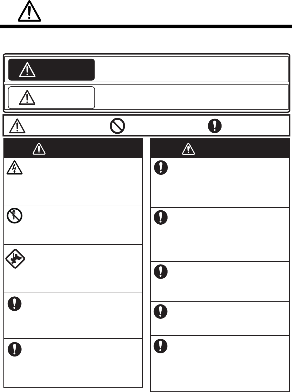
SAFETY INSTRUCTIONS
Mandatory Action
Prohibitive Action
WARNING
CAUTION
Warning, Caution
WARNING
The installer of the equipment must read the safety instructions before attempting to
install the equipment.
Indicates a potentially hazardous situation which, if not avoided,
could result in death or serious injury.
Indicates a potentially hazardous situation which, if not avoided,
can result in minor or moderate injury.
WARNING
Turn off the power at the
switchboard before beginning the
installation.
Fire or electrical shock can result if
the power is left on.
Do not open the equipment
unless you are well familiar with
electrical circuits.
Only qualified personnel should
work inside the equipment.
Be sure that the power supply is
compatible with the voltage rating
of the equipment.
Connection of an incorrect power
supply can cause fire or damage the
equipment.
Use only the specified power and
signal cable.
Fire or damage to the equipment
can result if a different cable is used.
Wear a safety belt and hard hat
when working on the antenna
unit.
Serious injury or death can result if
someone falls from the radar mast.
Do not disassemble or modify the
equipment.
Fire, electrical shock or serious
injury can result.
Construct a suitable service
platform from which to install the
antenna unit.
Serious injury or death can result if
someone falls from the radar mast.
Keep the objects away from the
antenna unit, so as not to impede
rotation of the antenna.
Fire, electrical shock or serious
injury can result.
Use the proper fuse.
Use of a wrong fuse can damage
the equipment or cause fire.
Do not depend one navigation
device for the navigation of the
vessel.
For the safety of vessel and crew,
the navigator must check all aids
available to confirm position.
SAFETY INSTRUCTIONS
ii
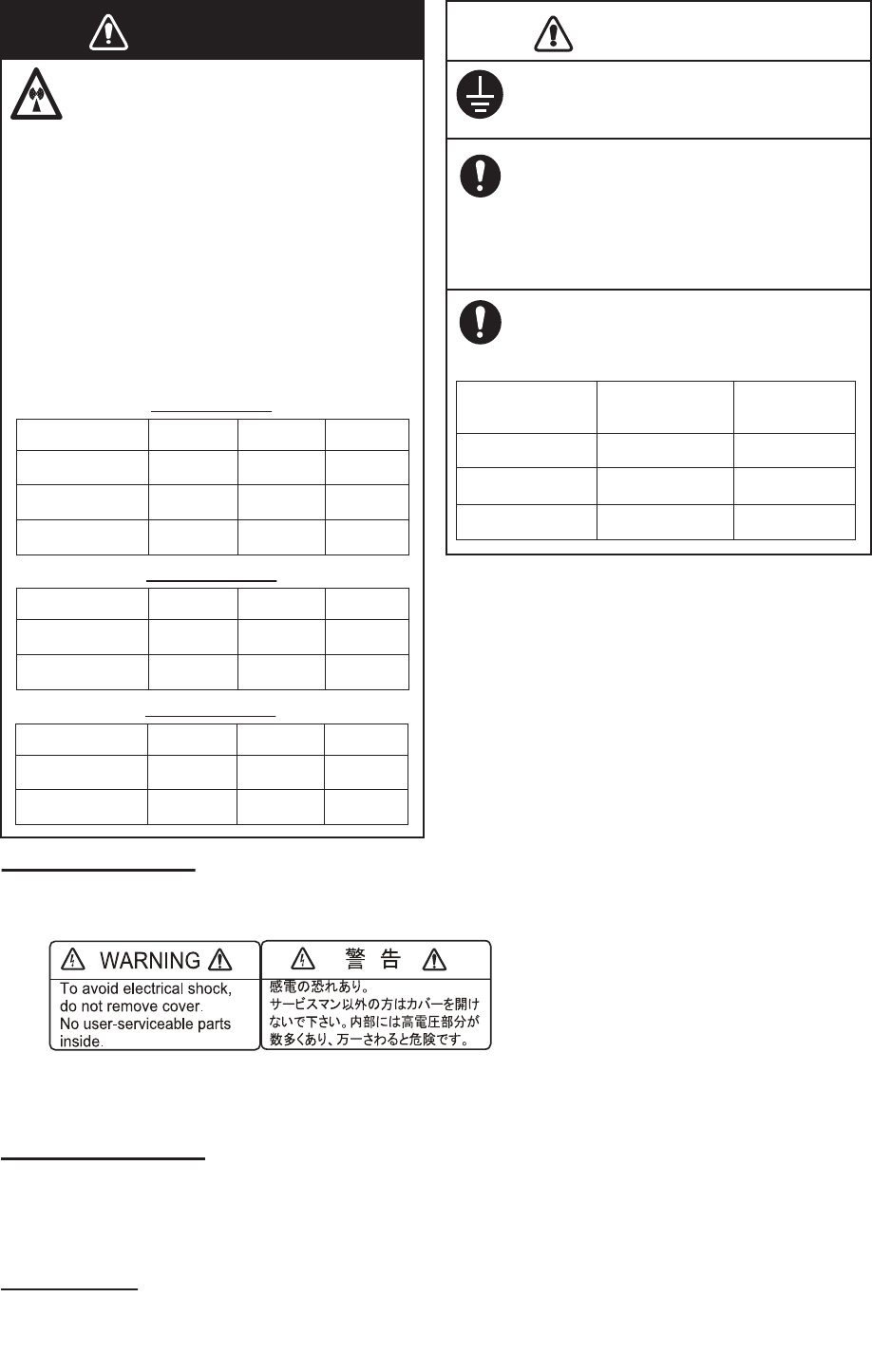
Ground the equipment to prevent
mutual interference.
WARNING LABEL
A warning label is attached to the antenna unit. Do not remove the label.
If the label is missing or damaged, contact your dealer about replacement.
Name: Warning Label (2)
Type: 03-129-1001-3
Code No: 100-236-743
It is recommended that you
connect the antenna unit to a
disconnecting device (circuit
breaker, etc.) to control the
power.
CAUTION
Observe the following compass safe
distances to prevent deviation of a
magnetic compass:
1.40 m
DRS6A X-Class
0.90 m
Model Standard
compass
Steering
compass
Importer in Europe
The following concern acts as our importer in Europe, as defined in DECISION No 768/2008/EC.
- Name: FURUNO EUROPE B.V.
- Address: Ridderhaven 19B, 2984 BT Ridderkerk, The Netherlands
Program No.
• 0359355-01.**
** denotes minor modifications.
1.80 m
DRS12A X-Class
1.15 m
2.10 m
DRS25A X-Class
1.35 m
The radar antenna emits
electromagnetic radio frequency
(RF) energy which can be
harmful, particularly to your eyes.
Never look directly into the
antenna aperture from a close
distance while the radar is in
operation or expose yourself to
the transmitting antenna at a
close distance.
Distances at which RF radiation
levels of 100, 50 and 10 W/m
2
exist
are given in the table below.
WARNING
0.1 m
XN10A
3 m0.5 m
100 W/m
2
50 W/m
2
10 W/m
2
Radiator
XN12A
XN13A
N/A 2.2 m0.4 m
N/A 1.9 m0.2 m
DRS6A X-Class
0.3 m
XN12A
3.1 m0.8 m
100 W/m
2
50 W/m
2
10 W/m
2
Radiator
XN13A
0.2 m 2.9 m0.7 m
DRS12A X-Class
0.8 m
XN12A
7.7 m1.7 m
100 W/m
2
50 W/m
2
10 W/m
2
Radiator
XN13A
0.7 m 6.8 m1.6 m
DRS25A X-Class
iii
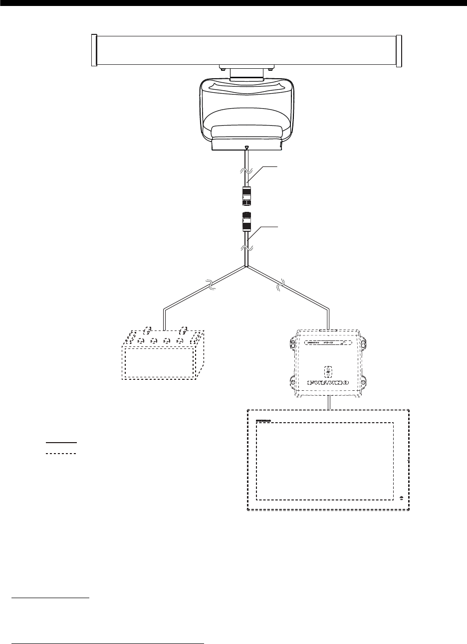
SYSTEM CONFIGURATION
This radar series is compatible with the FURUNO Multi Function Displays and software version
combinations shown below. The combination with other models may not operate properly.
• DRS6A X-Class
TZT9, TZT14 and TZTBB: Version 4.21 or later
TZTL12F and TZTL15F: Version 3.01 or later
• DRS12A X-Class and DRS25A X-Class
TZT9, TZT14 and TZTBB: Version 5.01 or later (Planned release: End of 2016)
TZTL12F and TZTL15F: Version 4.01 or later (Planned release: End of 2016)
: Standard supply
: Optional or local supply
Antenna Unit
RSB-134
Multi Function Display
NavNet TZtouch/Navnet TZtouch 2
Multi Function Display
NavNet TZtouch/Navnet TZtouch 2
Ethernet HUB
HUB-101
Ship's battery*
(24 VDC)
*: Connect the antenna unit to the ship's
battery via a switchboard.
Power/LAN cable
Cable assembly
iv
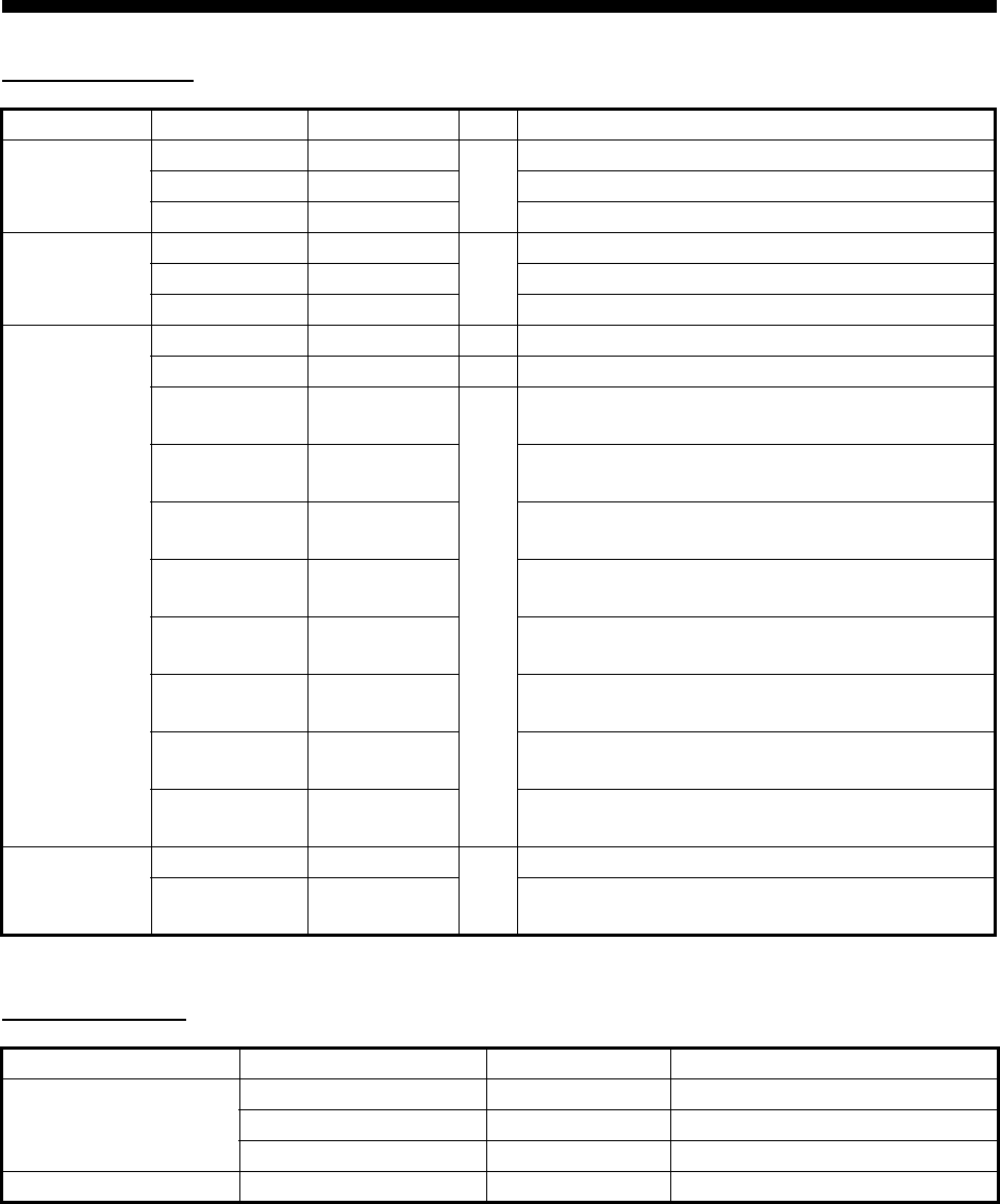
EQUIPMENT LISTS
Standard supply
*: Selectable for DRS6A X-Class only.
Optional supply
Name Type Code No. Qty Remarks
Scanner Unit RSB-134-112 -
1
For DRS6A X-Class
RSB-134-113 - For DRS12A X-Class
RSB-134-114 - For DRS25A X-Class
Radiator XN10A* -
1
3.4 ft
XN12A - 4 ft
XN13A - 6 ft
Installation
Materials
CP03-37101 001-426-290 1 For scanner unit
CP03-22901 008-523-690 1 For radiator
CP03-36400 000-027-211
1
Cable assembly (10 m), supplied for DRS6A X-
Class
CP03-36410 000-027-212 Cable assembly (15 m), supplied for DRS6A X-
Class
CP03-36420 000-027-213 Cable assembly (20 m), supplied for DRS6A X-
Class
CP03-36430 000-027-214 Cable assembly (30 m), supplied for DRS6A X-
Class
CP03-37400 000-033-082 Cable assembly (10 m) and fuse (10 A) for re-
placement, supplied for DRS12A/25A X-Class
CP03-37410 000-033-083 Cable assembly (15 m) and fuse (10 A) for re-
placement, supplied for DRS12A/25A X-Class
CP03-37420 000-033-084 Cable assembly (20 m), and fuse (10 A) for re-
placement supplied for DRS12A/25A X-Class
CP03-37430 000-033-085 Cable assembly (30 m) and fuse (10 A) for re-
placement, supplied for DRS12A/25A X-Class
Spare Parts SP03-18101 001-426-190
1
Fuse (5 A), supplied for DRS6A X-Class
SP03-18301 001-458-590 Fuse (10 A), supplied for DRS12A X-Class and
DRS25A X-Class
Name Type Code No. Remarks
LAN Cable MOD-Z072-020+ 001-167-880-10 2 m
MOD-Z072-050+ 001-167-890-10 5 m
MOD-Z072-100+ 001-167-900-10 10 m
Joint Box TL-CAT-012 000-167-140-10 For LAN cable extension
1
1. INSTALLATION AND WIRING
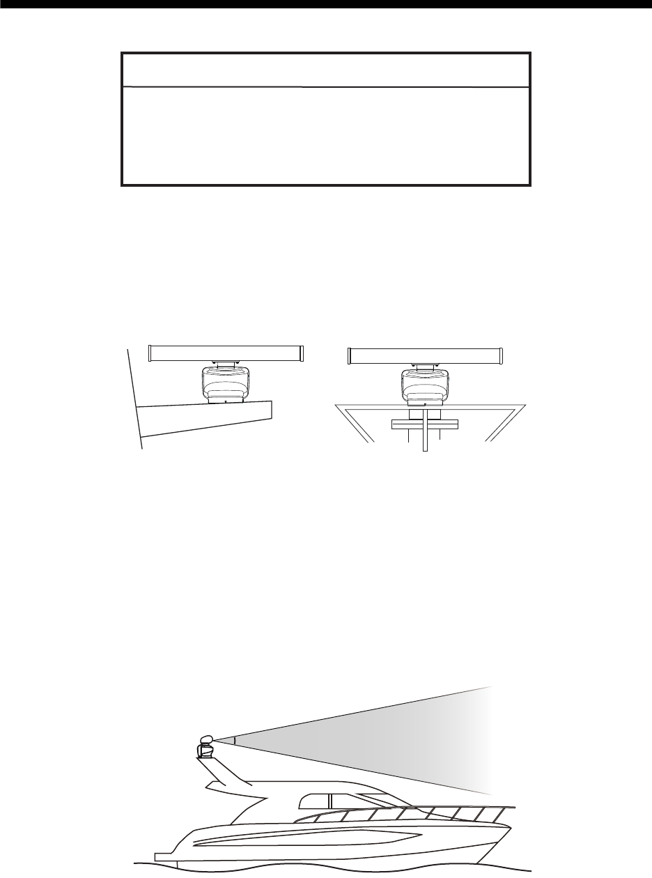
1.1 Mounting Considerations
Select a mounting location, keeping in mind in the following points:
• Install the antenna unit on the hardtop, radar arch or on a mast on an appropriate
platform.
• Locate the antenna where there is a good all-round view. Where possible, there
should be no obstructions to the scanning beam such as superstructure or rigging.
Obstructions cause shadow sectors and decrease the overall performance of the
radar. The loss of performance can cause false echoes and reduce the quality of
the observed images. A mast for instance, with a diameter considerably less than
the horizontal beam width of the radiator, will cause only a small shadow sector.
However, a horizontal spreader, or cross trees in the same horizontal plane as the
antenna unit, would be a much more serious obstruction. You would need to place
the antenna unit well above or below it. Be sure there are no metallic objects near
the antenna.
• It is rarely possible to place the antenna unit where a completely clear view in all
directions is available. After fitting the antenna, determining any shadow sectors,
their angle and bearing, and their influence on the radar is recommended.
NOTICE
Do not apply paint, anti-corrosive sealant or contact
spray to coating or plastic parts of the equipment.
Those items contain organic solvents that can damage
coating and plastic parts, especially plastic connectors.
(a) Common mast (b) Radar mast
Vertical beam angle = 22°
1. INSTALLATION AND WIRING
2
• In order to reduce electrical interference, avoid routing the power cable near other
electrical equipment on-board. Also, avoid running the cable in parallel with other
power cables.
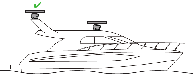
• It is not recommended to install the antenna unit on the hardtop of a cabin. Vibra-
tions from the antenna unit will pass through the hardtop and into the cabin.
• Setup the antenna unit position on the FURUNO Multi Function Display after install-
ing the unit, referring to the chapter 2. If the antenna unit position is not setup cor-
rectly, the radar echoes on the display may not be aligned with the actual target’s
bearing.
• Select a location that does not allow water to accumulate at the installation location.
• A magnetic compass will be affected if the antenna unit is too close to the compass.
Observe the compass safe distances mentioned in the SAFETY INSTRUCTIONS
to prevent interference to a magnetic compass.
• To ensure proper emission of radar waves, do not paint the radiator.
• Referring to the outline drawings at the back of this manual, allow space for main-
tenance and service.
• When this antenna unit is to be installed on a large vessel, consider the following
points:
• The supplied cable assembly runs between the antenna unit and display (or eth-
ernet HUB) and comes in lengths of 10 m, 15 m, 20 m or 30 m. Select the appro-
priate length when purchasing.
• Deposits and fumes from a funnel or other exhaust vent can adversely affect the
aerial performance and hot gases may distort the antenna unit. The antenna unit
must not be mounted where the temperature is more than 55°C (131°F).
Not recommended
1. INSTALLATION AND WIRING
3
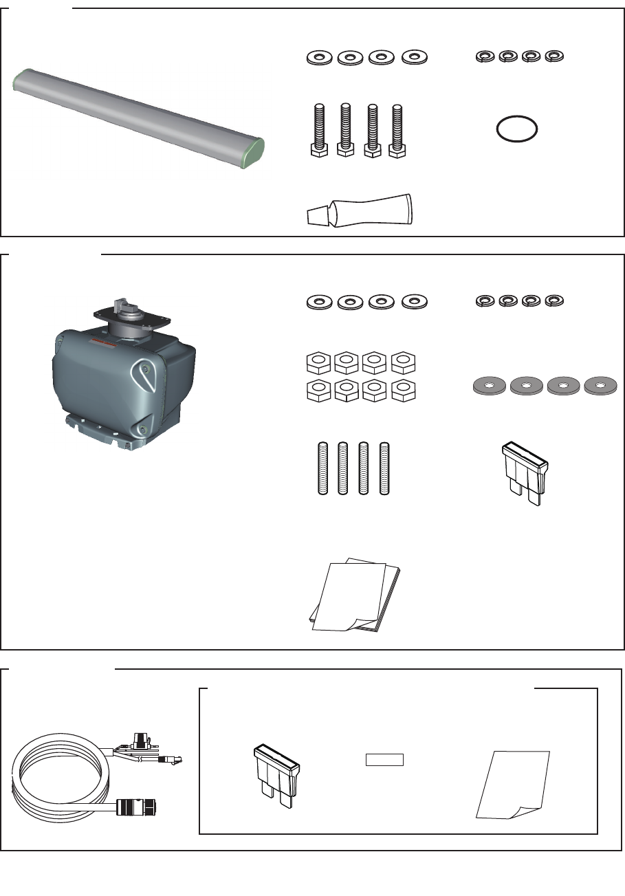
1.2 Included Items
•
Radiator
*
1
(1 pcs):
3.4 ft
*
2
, 4 ft or 6 ft
•
Scanner Unit (1 pcs)
Radiator
• O-ring (1 pcs)
• Flat washer (M8, 4 pcs) • Spring washer (M8, 4 pcs)
• Hex. bolt (M8×30, 4 pcs)
• Silicone rubber (1 pcs)
Scanner Unit
• Stud bolt (M12×70, 4 pcs)
• Flat washer (M12, 4 pcs) • Spring washer (M12, 4 pcs)
• Hex nut (M12, 8 pcs) • Corrosion-proof rubber pad
(4 pcs)
• Spare fuse (1 pcs)
(DRS6A X-Class: 5 A,
DRS12A/25A X-Class: 10 A)
• Documents (1 set):
Cable assembly
• Cable assembly*
1
(1 pcs):
10 m, 15 m, 20 m or 30 m
*
1
: Select the appropriate length when purchasing.
*
2
: Selectable for DRS6A X-Class only.
Supplied for DRS12A X-Class and DRS25A X-Class
㻔㻝㻜㻌㻭㻕
10A
• Fuse for replacement
(1 pcs)
• Label (1 pcs) • How to Replace the Fuse
(1 pcs)
1. INSTALLATION AND WIRING
4
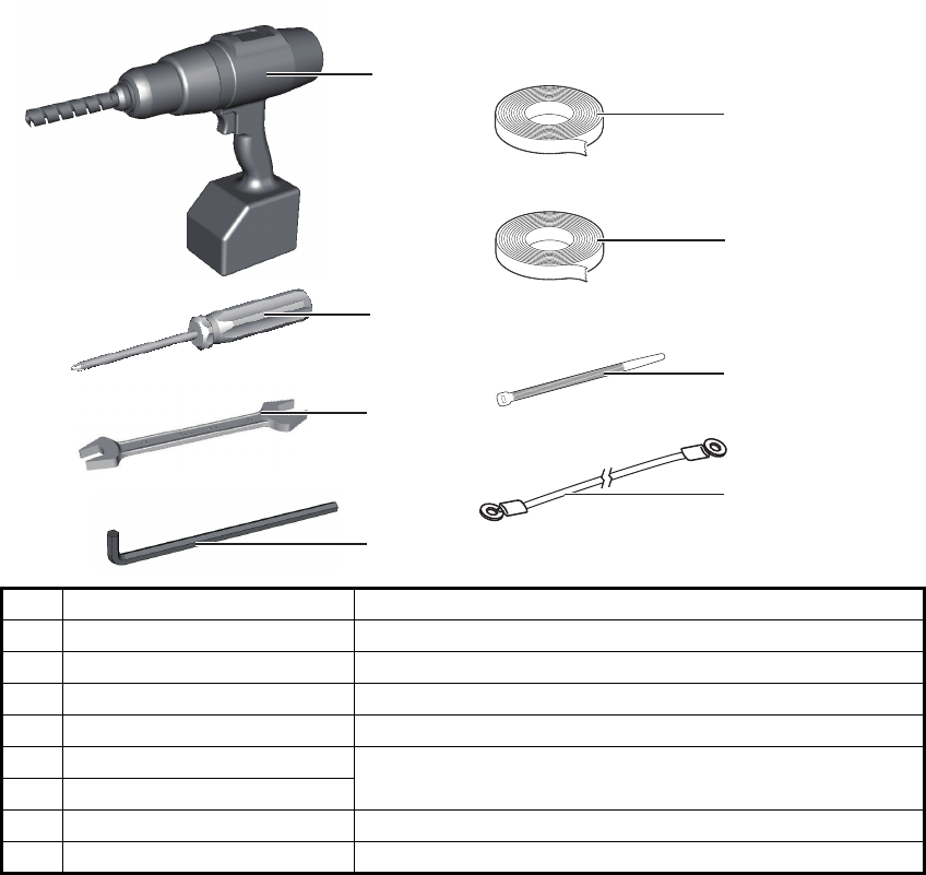
1.3 Required Tools and Materials
The following tools should be prepared in advance for this installation.
*: For cosmetic purposes, black color vinyl tape (cable color) is recommended.
No. Name Remarks
1Electrical drill For making the mounting holes, drill bit: 15 mm
2Phillips-head screw driver #3, for securing the cable cover
3Wrench For M8 (Hex. size 13 mm) and M12 (Hex. size 19 mm)
4Hex. L-wrench For fastening the stud bolts (Hex. size 6 mm)
5Self-vulcanizing tape For waterproofing the junction of connectors
6Vinyl tape*
7Cable tie For securing the cables
8Ground wire IV-2sq
1
2
3
5
7
4
6
8
1. INSTALLATION AND WIRING
5
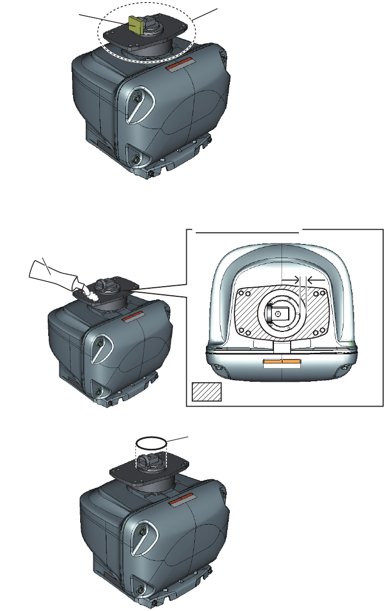
1.4 Fastening the Radiator to the Radiator Bracket
1. Remove the radiator cap from the radiator bracket.
2. Apply silicone rubber to the surface of the radiator bracket as shown in the figure
below.
3. Set the O-ring to the radiator bracket.
Radiator bracket
Radiator cap
Silicone rubber
Top view: Scanner unit
10 mm10 mm
: Silicone rubber application area
O-ring
1. INSTALLATION AND WIRING
6
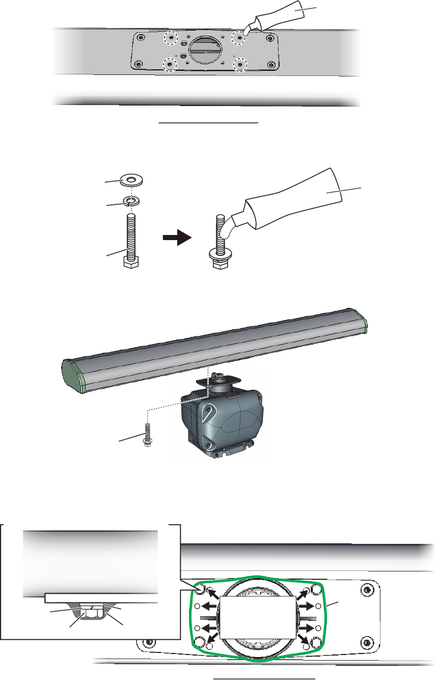
4. Apply silicone rubber to the thread holes on the bottom of the radiator (4 loca-
tions).
5. Prepare four bolt assemblies; pass the spring washer (M8) and flat washer (M8)
through the each hex bolt (M830) then apply silicone rubber.
6. Fasten the radiator to the radiator bracket, using four bolt assemblies prepared at
step 5.
7. Apply silicone rubber to the holes and bolts at the locations indicated with arrows
in the figure below. Also apply silicone rubber to the junction between the radiator
and the radiator bracket.
Bottom view: Radiator
Silicone rubber
Flat washer
Spring washer
Hex. bolt
Silicone rubber
Hex. bolt
(4 pcs)
Apply silicone
rubber to these
bolts and holes
Radiator
Bolt assembly - side view (detailed)
Apply silicone rubber
to the junction
between the radiator
and radiator bracket.
Apply silicone rubber
to the junction
between the radiator
and radiator bracket.
Flat washer
Spring
washer
Hex. bolt Silicone rubber
Radiator - bottom view
1. INSTALLATION AND WIRING
7
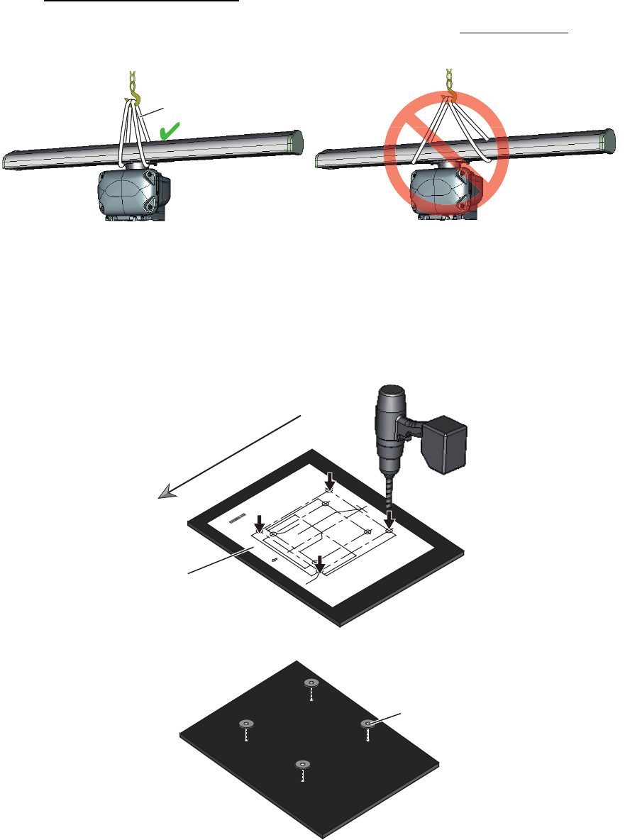
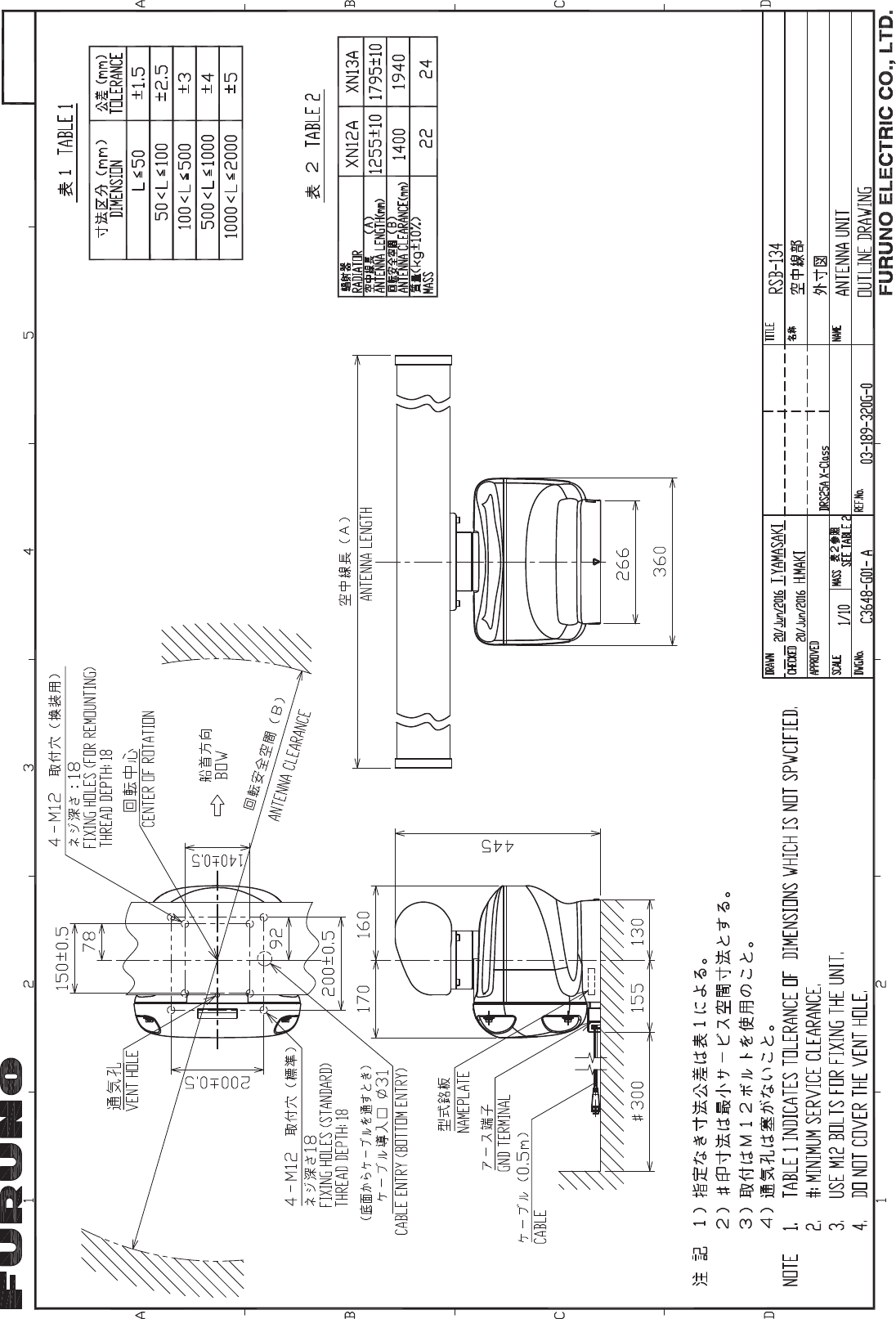
1.5 Mounting the Antenna Unit
The antenna unit can be mounted using the fixing holes on the outside (200 200 mm)
or inside (140 150 mm) the antenna unit. Normally, use the outside fixing holes.
When 140 150 mm fixing holes already exist on the mounting platform, use the in-
side fixing holes.
Hoisting the antenna unit
• When you hoist the antenna unit, set the belt slings to the radiator bracket. Do not
set the belt slings to the radiator, the radiator may get damaged.
• Hoist the antenna unit slowly. If the antenna unit is hoisted too quickly, the bracket
can be damaged.
1. Set the supplied mounting template to the mounting location, then drill four fixing
holes in the mounting location.
Note: The holes must be parallel with the fore and aft line.
2. Attach four corrosion-proof rubber pads (supplied) to the mounting holes.
WRONG: Belt slings are set to the radiator. OK: Belt slings are set to the radiator bracket.
Belt sling
CABLE ENTRANCE AT SCANNER FOR DRS4A/6A/12A/25A
䝇䜻䝱䝘ഃ䜿䞊䝤䝹ᑟධཱྀ䠄㻰㻾㻿㻠㻭㻛㻢㻭㻛㻝㻞㻭㻛㻞㻡㻭䛾䜏䠅
PP'')
PP'')
sPP'')
PP'')
sPP'')
CENTER OF ANTENNA ROTATION
䜰䞁䝔䝘ᅇ㌿୰ᚰ
PP'')
ྲྀ✰
4-䃥15
FIXING HOLES
ྲྀ✰䚷㻔⏝㻕
4-䃥15 (#: 4 places)
FIXING HOLES
( FOR RETROFITTING)
Note: This template may have expanded or shrunk slightly.
Please confirm dimensions before use.
ὀព㻦㻌㻌ᮏᆺ⣬䛿ಖᏑ≧ែ䛻䜘䜚ⱝᖸఙ⦰䛩䜛ሙྜ䛜䛒䜚䜎䛩䚹
㻌㻌㻌㻌㻌㻌㻌㻌㻌⏝䛾㝿䛻䛿ᑍἲ䜢☜ㄆ䛧䛶䛟䛰䛥䛔䚹㻌
BOW
⯪㤳᪉ྥ
June 2015 Printed in Japan
C32-00703-A1
DRSシリーズ レーダーセンサー(オープン型)
ᆺ⣬
DRS SERIES OPEN RADAR SENSOR
MOUNTING TEMPLATE
䢲䢲䢲䢳䢸䢹䢶䢷䢻䢳䢲
BowBow
Mounting template
Corrosion-proof rubber pad
1. INSTALLATION AND WIRING
8
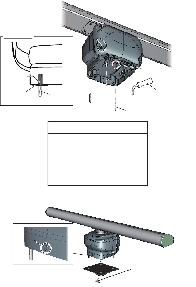
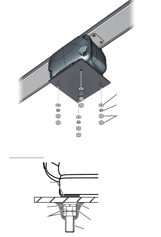
3. Apply silicone rubber to the thread of the stud bolts (M1270, 4 pcs).
Note: Apply silicone rubber to the part of thte bolt threads that are inside the bolt
hole (see the figure at step 4).
4. Insert four stud bolts into the threaded holes in the antenna unit.
The stud bolts must make contact with the bottom of the threaded holes.
Note: Do NOT cover the vent hole at the bottom of the unit.
5. Place the antenna unit on the mounting platform with the BOW mark on the unit
aligned with the ship’s bow.
Stud bolt
Silicone rubber
Detailed view
Vent hole:
Do NOT cover this hole.
Silicone
rubber
Stud bolt
Corrosion-proof
rubber pad
Do not fasten stud bolts tightly after
the bolts contact with the bottom of
the threaded holes.
If the bolts are fastened excessively, the
chassis bottom may be damaged and
malfunction can result.
NOTICE
BOW mark
BOW mark
Bow
Bow
1. INSTALLATION AND WIRING
9
6. Secure the antenna unit, using the supplied flat washers (M12, 4 pcs), spring
washers (M12, 4 pcs), and hex. nuts (M12, 8 pcs).
7. Apply silicone rubber to the flat washers, spring washers, and hex. nuts.
Flat washer
Spring washer
Hex. nut
Silicone rubber
Corrosion-proof
rubber pad
Flat washer
Spring washer
Hex. nut
Stud bolt
Detailed view
1. INSTALLATION AND WIRING
10
1.6 Wiring
Wiring considerations
• Turn the power at the switchboard off before beginning the wiring.
• For DRS12A X-Class and DRS25A X-Class, the 5 A fuse in the fuse holder (sup-
plied with the cable assembly) must be replaced with the supplied 10 A fuse. Also,
attach the supplied fuse rating label to the fuse holder. For details, see “How to Re-
place the Fuse” (C32-01604).
• The cable assembly and power/LAN cables have connector(s). Do NOT cut the ca-
ble assembly and power/LAN cables even if the cables are run through a radar
mast.
• When you replace the DRS4A/6A/12A/25A with the DRS6A X-Class/DRS12A X-
Class/DRS25A X-Class, the existing cable cannot be used. Use only the cable as-
sembly supplied with this radar sensor
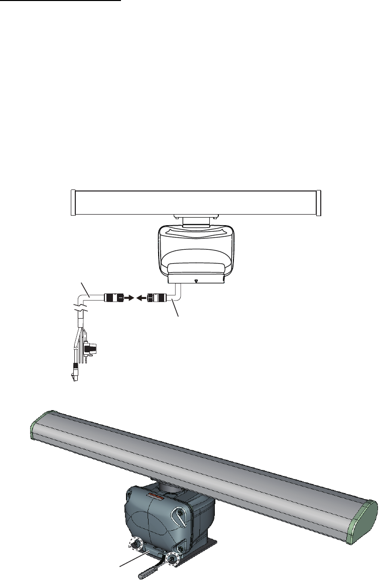
1. Unfasten two screws circled in the following figure to remove the cable cover.
2. Connect the cable assembly (supplied) to the power/LAN cable that is pre-at-
tached to the antenna unit.
Power/LAN cable:
Pre-attached to the antenna unit.
Cable assembly
Cable coverCable cover
1. INSTALLATION AND WIRING
11
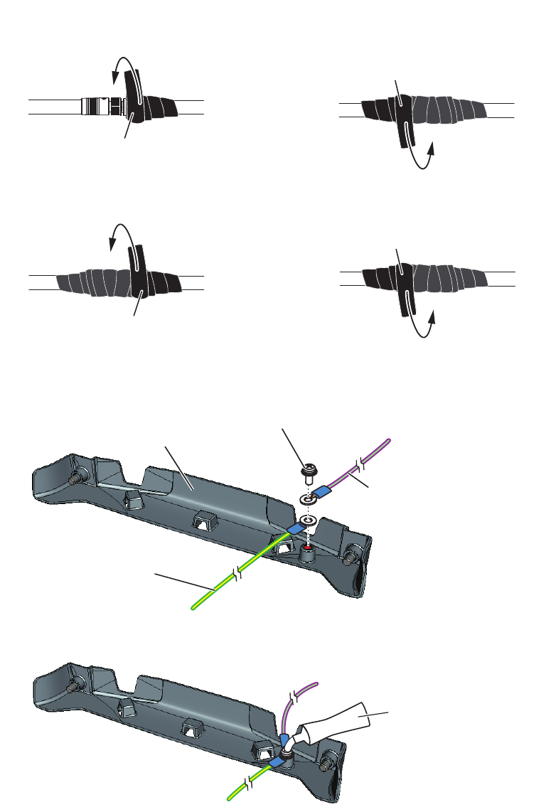
3. Wrap the junction of the connectors with self-vulcanizing tape and vinyl tape (local
supply) for waterproofing as follows:
4. As shown in the figure below, secure the ground wire from the ship's ground (IV-
2sq, local supply) and ground wire from the antenna unit, using the terminal screw
(M4x10) that is pre-attached to the cable cover.
5. Apply silicone rubber to the ground terminal after fastening the terminal screw.
Self-vulcanizing tape
1) Wrap the junction of the connectors
with one layer of self-vulcanizing
tape.
2) Change wrap direction and wrap
one layer of the self-vulcanizing
tape again.
Self-vulcanizing tape
3) Wrap one layer of the vinyl tape over
the self-vulcanizing tape.
Vinyl tape
4) Change wrap direction and wrap one
layer of the vinyl tape again.
Vinyl tape
Ground wire from
the ship’s ground
*: Pre-attached to the cable cover.
Ground wire* from
the antenna unit
Cable cover
Terminal screw*
Silicone rubber
1. INSTALLATION AND WIRING
12
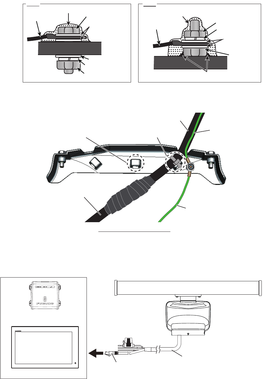
6. Secure the ground wire to the ship’s ground.
The figures shown below are examples for grounding.
7. Secure the cable assembly to the cable cover with the cable ties (local supply) as
shown in the figure below.
8. Reattach the cable cover.
9. Connect the LAN connector of the cable assembly to a LAN port on the FURUNO
Multi Function Display or Ethernet HUB.
Note 1: Do not connect the LAN connector to on-board LAN.
Ex.1 Ex.2
Silicone rubber Silicone rubber
Hex. bolt
Flat washer
Flat washer
Spring washer
Hex. nut
Ground wire
Ground wire Hex. nut
Spring washer
Flat washer
Hex. nut
Weld here.
Fix the cable to this cable
clamp, using a cable tie.
Fix the cable to this cable
clamp, using a cable tie. Ground wire from
the ship's ground
Ground wire from
the ship's ground
Cable assemblyCable assembly
Power/LAN cablePower/LAN cable
Ground wire from
the antenna unit
Ground wire from
the antenna unit
If the cable is run through a
radar mast and the bottom of the
unit, fix the cable to this cable
clamp.
If the cable is run through a
radar mast and the bottom of the
unit, fix the cable to this cable
clamp.
Cable cover - bottom view
Cable assembly
LAN connector
Ethernet HUB
OR
FURUNO Multi Function Display
1. INSTALLATION AND WIRING
13
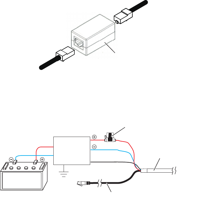
Note 2: When LAN cable extension is needed, use the optional LAN cable (MOD-
Z072) and joint box (TL-CAT-012). After connection is completed, wrap the con-
nector with vinyl tape to waterproof the LAN connector.
10. Connect the power wires to the ship’s battery (24 VDC).
• Red wire: Connect to the positive terminal. The red wire has the fuse holder.
• Blue wire: Connect to the negative terminal.
• Black wire: The black wire is a shielding wire for grounding.
Note 1: The antenna unit has no power switch. Connect the antenna unit to a dis-
tribution switchboard with a switch for power control.
Note 2: If the voltage of the ship’s battery is 12 VDC, prepare a DC-to-DC con-
verter whose output current is 10 A or more.
Note 3: The antenna unit cannot accept input voltage of more than 24 VDC.
Joint box
LAN cable
To antenna unit
Cable assembly
Shield
Distribution
switchboard
Ship's battery
(24 VDC)
Fuse holder
Red
Blue
Black
14
2. INITIAL SETUP
This radar series is compatible with the FURUNO Multi Function Displays and soft-
ware version combinations shown below. The combination with other models may not
operate properly.
• DRS6A X-Class
TZT9, TZT14 and TZTBB: Version 4.21 or later
TZTL12F and TZTL15F: Version 3.01 or later
• DRS12A X-Class and DRS25A X-Class
TZT9, TZT14 and TZTBB: Version 5.01 or later (Planned release: End of 2016)
TZTL12F and TZTL15F: Version 4.01 or later (Planned release: End of 2016)
Turn on the antenna unit and FURUNO Multi Function Display. Initial setup for this an-
tenna must be done on the FURUNO Multi Function Display.
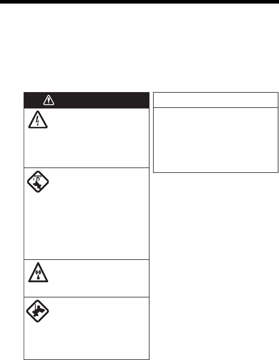
Before turning on the radar, be sure
no one is near the antenna.
Prevent the potential risk of being
struck by the rotating antenna, which
can result in serious injury or death.
WARNING
The radar antenna emits
electromagnetic radio frequency
(RF) energy which can be
harmful, particularly to your eyes.
Never look directly into the
antenna aperture from a close
distance while the radar is in
operation or expose yourself to
the transmitting antenna at a
close distance.
Distances at which RF radiation
levels of 100, 50 and 10 W/m
2
exist
are given in the table below.
WARNING
0.1 m
XN10A
3 m0.5 m
100 W/m250 W/m210 W/m2
Radiator
XN12A
XN13A
N/A 2.2 m0.4 m
N/A 1.9 m0.2 m
DRS6A X-Class
0.3 m
XN12A
3.1 m0.8 m
100 W/m250 W/m210 W/m2
Radiator
XN13A
0.2 m 2.9 m0.7 m
DRS12A X-Class
0.8 m
XN12A
7.7 m1.7 m
100 W/m250 W/m210 W/m2
Radiator
XN13A
0.7 m 6.8 m1.6 m
DRS25A X-Class
2. INITIAL SETUP
15
2.1 Initial Setup for TZT9/TZT14/TZTBB
1. Press the Home key (or tap the Home icon).
2. Select [Menu] on the menu icon bar to open the main menu.
3. Select [Radar].
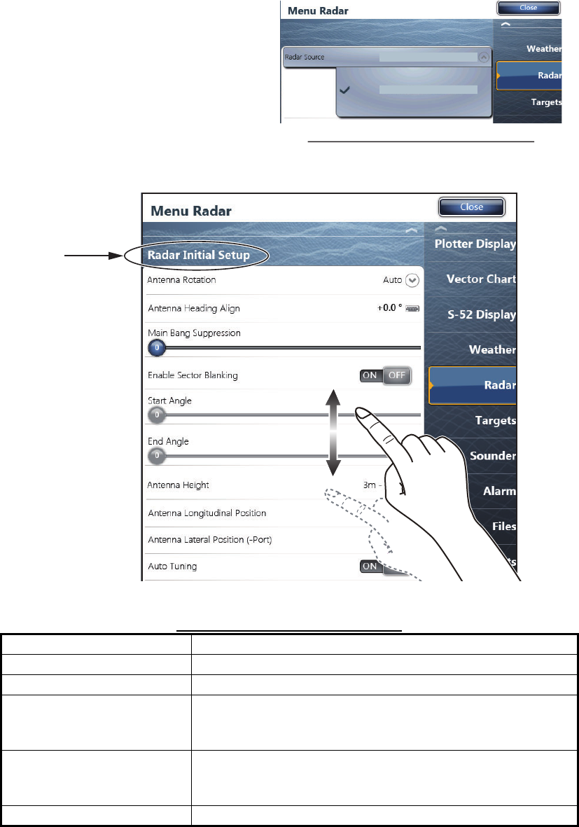
4. Select [Radar Source] on the [Menu Radar] sub menus, then select the radar type
connected.
Note: If the antenna unit is con-
nected but does not appear in the
[Radar Source] list, close the list
and open it again. The name of the
antenna unit should appear with a
check mark, as in the example to
the right.
5. Drag the [Menu Radar] sub menus
to find the menu item [Radar Initial Setup].
6. Set the items referring to the table shown below
Menu Radar (Radar Initial Setup)
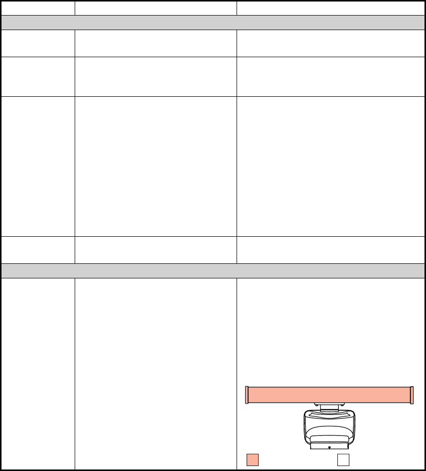
Menu item Description
[Antenna Rotation] Select the antenna rotation speed.
[Antenna Heading Align] See "How to align the antenna heading" on page 16.
[Main Bang Suppression] If main bang appears at the screen center, slide the circle
icon, while watching the radar echo on the left-side of the
display, until the main bang disappears.
[Enable Sector Blanking]/
[Enable Sector Blanking2]
Up to two sectors may be selected for blanking (no trans-
mission). Select [ON] to enable this feature. Set the start
and end angles (0° to 359°).
[Antenna Height] Select the height of the antenna above the waterline.
RDxxxxxx - DR
S
6A X-
C
lass
RDxxxxxx - DR
S6
A X-
C
lass
Display example for DRS6A X-Class
Title
2. INITIAL SETUP
16
How to align the antenna heading
You have mounted the antenna unit facing straight ahead in the direction of the bow.
Therefore, a small but conspicuous target dead ahead visually should appear on the
heading line (zero degrees).
You may observe a minor bearing error on the display. This is due to the difficulty in
orienting the radar accurately. The following adjustment will compensate for the error.
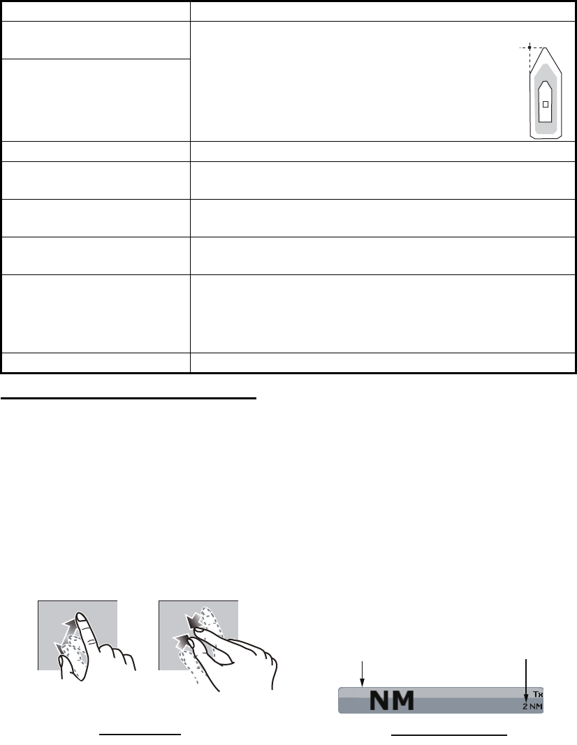
1. Select a range between 0.125 and 0.25 NM and set the mode to “head up“.
You can select a range by a pinch action. The range and range ring interval ap-
pear at the bottom left of the screen.
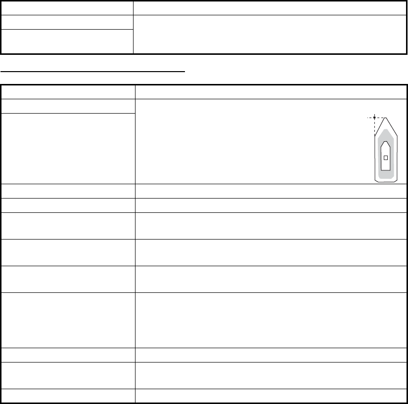
[Antenna Longitudinal Po-
sition]
Referring to the figure on the right, enter the
radar antenna positioning bow-stern (Longi-
tudinal) and port-starboard (Lateral) position
from the origin.
[Antenna Lateral Position (-
Port)]
[Auto Tuning] Enable/disable auto tuning for the connected radar.
[Tuning Source] Select the radar range to tune manually, which is used for
the dual-range display.
[Manual Tuning] Manually tune the radar. Not available when [Auto Tuning]
is enabled.
[Radar Monitoring] Display various information regarding the connected ra-
dar.
[Radar Optimization] Automatically adjust magnetron output and tuning for the
connected radar.
Note: Be sure to perform [Radar Optimization] after re-
placing the magnetron.
[ARPA Advanced Settings] Do not change these settings.
Menu item Description
Origin
1
Range Range ring interval
Range indications
Zoom outZoom in
Pinch action
2. INITIAL SETUP
17
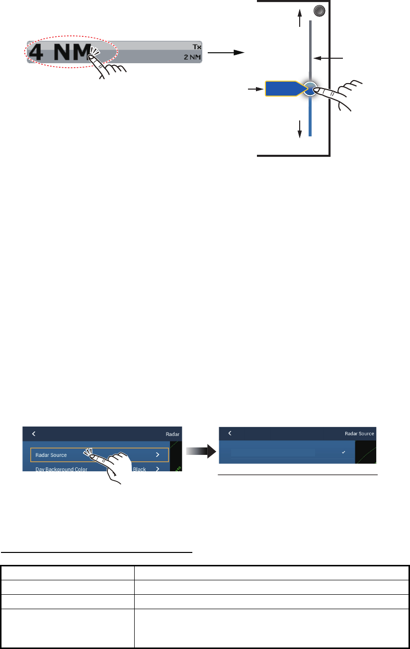
For TZTBB, you can also control the range in the operation as follows. Tap the
radar scale box at the bottom left-hand corner of the screen to display the slider
bar. Drag the circle icon to set the range scale.
2. Turn the vessel’s bow toward a target.
3. Press the Home key (or tap the Home icon), then select [Menu] icon, [Radar], and
[Antenna Heading Align] in that order to show the numeric software keyboard.
4. Key in the offset value so that the target is at the very top of the screen (setting
range: +/- 0° to 180°, +: clockwise direction, -: counterclockwise direction), then
tap [Save].
5. Confirm that the target echo is displayed at correct bearing on the screen.
2.2 Initial Setup for TZTL12F/TZTL15F
1. Tap the [Home] icon to show the home screen and display mode settings.
2. Tap [Radar] from the [Settings] menu.
3. Tap [Radar Source], then select the appropriate antenna unit.
Note: If the antenna unit is connected but does not appear in the [Radar Source]
list, close the list and open it again. The name of the antenna unit should appear
with a check mark, as in the example below.
4. Drag the [Radar] menu display the menu item [Radar Initial Setup], then tap
[Radar Initial Setup].
5. Referring to the tables below, set up the radar.
[Radar] menu - [Radar Initial Setup]
Menu item Description
[Antenna Rotation] Select the antenna rotation speed.
[Antenna Heading Align] See "How to align the antenna heading" on page 19.
[Main Bang Suppression] If main bang appears at the screen center, slide the circle
icon so that the main bang disappears, while watching the
radar echo at the left-hand side of the display.
Tap the area circled in the dashed line to
display the slider bar.
Note: You can switch between transmit and
stand-by by tapping the right side of the
radar scale box.
Drag the circle
icon to set the
range scale.
Slider bar
Zoom in
Zoom out
4NM
Current
range
RDxxxxxx - DRS6A X-Class
Display example for DRS6A X-Class
2. INITIAL SETUP
18
[Radar] menu - [Antenna Position]
[Enable Sector Blanking] Up to two sectors may be selected for blanking (no trans-
mission). Select [ON] to enable this feature. Set the start
and end angles (0° to 359°).
[Enable Sector 2 Blanking]
Menu item Description
[Longitudinal (from bow)] Referring to the figure on the right, enter the
radar antenna positioning bow-stern (Longi-
tudinal) and port-starboard (Lateral) position
from the origin.
[Lateral (-Port)]
[Antenna Height] Select the height of the antenna above the waterline.
[Auto Tuning] Enable/disable auto tuning for the connected radar.
[Tuning Source] Select the radar range to tune manually, which is used for
the dual-range display.
[Manual Tuning] Manually tune the radar. Not available when [Auto Tuning]
is enabled.
[Radar Monitoring] Display various information regarding the connected ra-
dar.
[Radar Optimization] Automatically adjust magnetron output and tuning for the
connected radar.
Note: Be sure to perform [Radar Optimization] after re-
placing the magnetron.
[ARPA Advanced Settings] Do not change these settings.
[Set Hardware To Factory
Default]
Resets the radar selected at [Radar Source] to factory de-
fault.
[Reset Default Settings] Resets [Radar] menu settings to default.
Menu item Description
Origin
2. INITIAL SETUP
19
How to align the antenna heading
You have mounted the antenna unit facing straight ahead in the direction of the bow.
Therefore, a small but conspicuous target dead ahead visually should appear on the
heading line (zero degrees).
You may observe a minor bearing error on the display. This is due to the difficulty in
orienting the radar accurately. The following adjustment will compensate for the error.
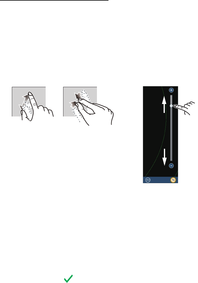
1. Set your radar with 0.125 and 0.25 NM range and the head up mode.
The range scale can be selected two ways, as shown below. The slider bar can
be shown or hidden with [Show Scale Slider] in the [Settings] - [Radar] menu.
2. Turn the vessel’s bow toward a target.
3. Tap the [Home] icon to show the home screen and display mode settings.
4. Tap [Radar] to show the [Radar] menu.
5. Drag the [Radar] menu to show the [RADAR INITIAL SETUP] menu.
6. Tap [Antenna Heading Align].
7. Key in the offset value so that the target is displayed at the very top of the screen
(setting range: +179.9° to -180°, +: clockwise direction, -: counterclockwise direc-
tion), then tap the icon.
8. Confirm that the target echo is displayed at correct bearing on the screen.
Zoom in Zoom out
Method 1: Pinch screen
Method 2: Drag slider
(or tap bar or +, - icons)
3 NM
Zoom in
Zoom in
Zoom out
Zoom out
20
3. MAINTENANCE, TROUBLE
SHOOTING
Periodic checks and maintenance are important for proper operation of any electronic
system. This chapter contains maintenance and troubleshooting instructions to be fol-
lowed to obtain optimum performance and the longest possible life of the equipment.
Before attempting any maintenance or troubleshooting procedure please review the
safety information below and at the front of this manual. If you cannot restore normal
operation after following the troubleshooting procedures, do not attempt to check in-
side any unit; there are no user serviceable parts inside. Contact your dealer to check
the equipment.
Do not apply paint, anti-corrosive
sealant or contact spray to coating or
plastic parts of the equipment.
Those items contain organic solvents
that can damage coating and plastic
parts, especially plastic connectors.
WARNING NOTICE
Do not open the equipment.
Hazardous voltage which can
cause electrical shock exists
inside the equipment. Only
qualified personnel should work
inside the equipment.
Turn off the antenna unit
before servicing the unit.
Post a warning sign near the
switch indicating it should
not be turned on while the
antenna unit is being
serviced.
Prevent the potential risk of
being struck by the rotating
antenna.
A transmitting radar antenna
emits electromagnetic waves,
which can be harmful,
particularly the eyes.
Wear a safety belt and hard
hat when working on the
antenna unit.
Serious injury or death can
result if someone falls from the
radar antenna mast.
3. MAINTENANCE, TROUBLE SHOOTING
21
3.1 Maintenance
Regular maintenance is important for good performance. Check the points mentioned
below every 3 to 6 months to keep the antenna unit in good working order.
Check point Action Remedy, remarks
Check points every 3 to 6 months
Cable Check that all cables are firmly
connected and are not damaged.
• Connect a cable if it has loosened.
• Replace damaged cables.
Exposed
bolts and nuts
Check that bolts and nuts are not
corroded and are securely fas-
tened.
• Replace corroded bolts.
• Tighten loosened bolts.
• Coat new bolts with marine sealant.
Radiator Dust, dirt and salt deposits on
the radiator cause signal attenu-
ation, resulting in loss of sensitiv-
ity.
• Wipe radiator with a freshwater-
moistened cloth.
• The radiator is made of AES (Acry-
lonitrile-Ethylene-Styrene) resin.
Therefore, do not used gasoline,
benzene and the like to clean the ra-
diator.
• If the radiator is iced, use a wooden
or plastic headed hammer to re-
move the ice. DO NOT use a steel
hammer.
Ground con-
nection
Check for tight connection and
rust.
• Fasten if loosened.
• Remove rust if present.
Check points every year
Check the scanner unit for rust,
corrosion and chipped paint.
• If the scanner unit has rusted or the
paint has chipped, paint the affected
area.
• Paint only the scanner unit. Do not
paint the antenna (see figure be-
low). Paint on the antenna can
cause loss of sensitivity and crack
the antenna.
: Do NOT paint. : Painting area
3. MAINTENANCE, TROUBLE SHOOTING
22
3.2 Troubleshooting
The table below provides simple troubleshooting procedures to restore normal opera-
tion. If you cannot restore normal operation, contact your dealer for advice.
3.3 Replacement of Fuse
The fuse in the fuse holder on the supplied cable assembly protects the antenna unit
from overcurrent and equipment fault. If you cannot turn on the power, check the fuse
to see if it has blown. If the fuse has blown, find the reason before you replace the fuse.
If the fuse blows again after the replacement, contact your dealer.
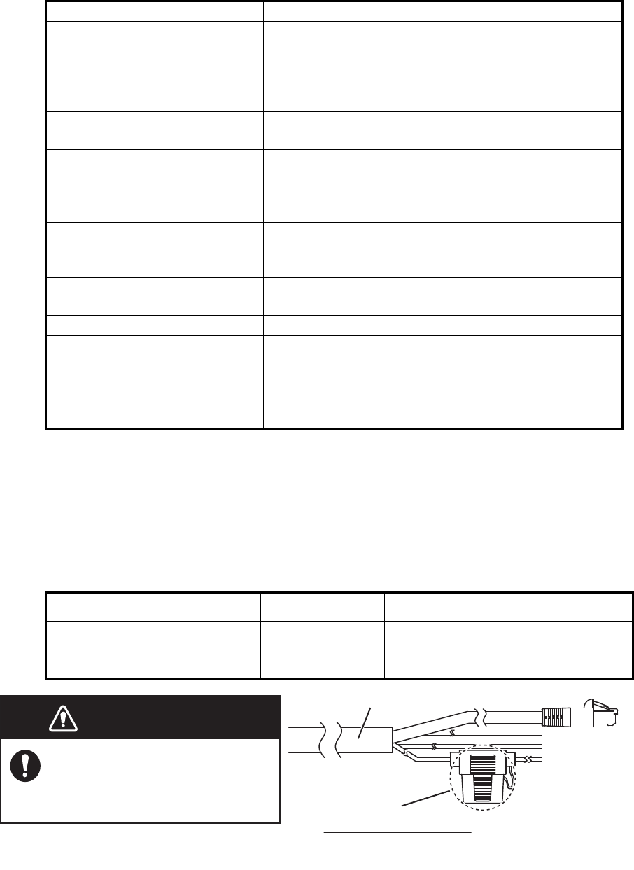
Problem Remedy
The multi function display can-
not control the radar.
• Check that all cables are tightly fastened.
• Check if the radar source setting is correct.
• Check if the fuse of the cable assembly has blown.
• Check that the power supply is compatible with the
voltage rating of the antenna unit (24 VDC).
Marks and characters appear,
but echoes do not appear.
• Check that the antenna cable is tightly fastened.
• Check the cables for damage.
Picture is not updated or the
picture freezes.
• Check that all cables are tightly fastened.
• Check the cables for damage.
• If the picture has frozen, reboot the multi function
display.
You tuned the receiver or in-
creased the gain, but radar
echoes are too week.
• The magnetron may required replacement. Contact
your dealer.
You changed the range, but the
radar picture does not change.
• Try to change the range again.
• Reboot the multi function display.
Poor discrimination in range. • Adjust the sea control.
Range rings are not displayed. • Check if the range rings is turned on in the menu.
You set the radar in the transmit
state. The "TX screen" appears
momentarily, but the radar soon
goes into stand-by.
• The overload protection has activated. To restore
normal operation, turn off all equipment in the net-
work. Wait a few seconds then turn on all the equip-
ment.
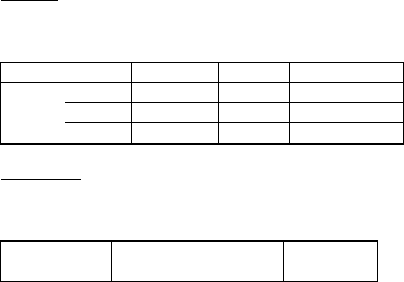
Name Type Code No. Remarks
Fuse FRU-2P5S-FU-5A-B 000-168-869-10 5 A fuse For DRS6A X-Class
ATV10A60V 000-192-660-10 10 A fuse For DRS12A/25A X-Class
WARNINGWARNING
Use the proper fuse.
Use of a wrong fuse can cause
fire or damage the equipment.
Fuse holder
How to replace the fuse
Open the fuse holder cover and replace
the fuse. Then close the cover.
Cable assembly
3. MAINTENANCE, TROUBLE SHOOTING
23
3.4 Life of Parts
Magnetron
When a magnetron reaches the end of its life, target echoes become weak and do not
appear on the display. If long-range performance appears to have declined, contact
your dealer about replacement of the magnetron.
Antenna Motor
When an antenna motor reaches the end of its life, the antenna’s rotation may stop or
abnormal noise sounds from the antenna unit. If such symptom occurs, contact your
dealer about replacement of the antenna motor.
Name Type Code No. Approx. Life Remarks
Magnetron MAF1422B 000-158-788-12 5,000 hours For DRS6A X-Class
FNE1201 001-245-890 5,000 hours For DRS12A X-Class
MG5436 000-140-762-13 5,000 hours For DRS25A X-Class
Name Type Code No. Approx. Life
Antenna Motor DJ8G-23B48H 001-436-400 10,000 hours

FURUNO
DRS6A/12A/25A X-Class
SP - 1 E3646S01A-M
SPECIFICATIONS OF RADAR SENSOR
DRS6A/12A/25A X-Class
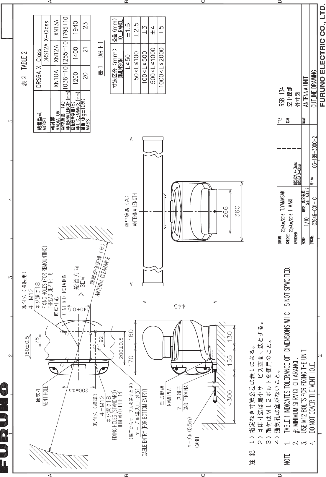
1 ANTENNA UNIT
1.1 Antenna type Slotted waveguide array
1.2 Antenna length 3.4 ft (XN10A), 4 ft (XN12A), 6 ft (XN13A)
1.3 Horizontal beam width 2.3° (XN10A), 1.9° (XN12A), 1.4° (XN13A)
Radiator type XN10A for DRS6A X-Class only
1.4 Vertical beam width 22°
1.5 Gain 27.5 dBi (XN10A), 28.5 dBi (XN12A), 30 dBi (XN13A)
1.6 Sidelobe attenuation
XN10A -20 dB (within ±10°), -28 dB (±10° or more)
XN12A -24 dB (within ±10°), -30 dB (±10° or more)
XN13A -28 dB (within ±10°), -35 dB (±10° or more)
1.7 Rotation 24/36/48 rpm range coupled or 24 rpm fixed
1.8 Relative wind load 70 kn or less
2 RADAR FUNCTION
2.1 Tx frequency 9410 ±30 MHz
2.2 Output power
DRS6A X-Class 6 kW nominal
DRS12A X-Class 12 kW nominal
DRS25A X-Class 25 kW nominal
2.3 Duplexer Ferrite circulator with diode limiter
2.4 Intermediate frequency 60 MHz
2.5 Range, Pulse length and Pulse Repetition Rate (PRR)
Range (NM) Pulse length (s) PRR (Hz. approx.)
0.125 to 0.75 0.08 3000
1 to 1.5 0.15 1500
2 0.3 1000
3 to 4 0.5 600
6 to 8 0.8 600
12 to 64 1.2 600
72 to 120 1.2 550
2.6 Minimum range 25 m
2.7 Range resolution 20 m
2.8 Range accuracy 1% of range in use or minimum VRM, whichever is the greater
2.9 Bearing resolution 2.3 (XN10A), 1.9° (XN12A), 1.4° (XN13A)
2.10 Bearing accuracy Within ±1°
2.11 Pre-heating time 90 s approx.
2.12 Target tracking (TT) Auto or manual acquisition: 30 targets in 32 NM
Past position: 5/10 pts on all activated targets
Vector time: 1 to 60 min.
3 INTERFACE
LAN: 1 port, Ethernet, 100Base-TX
FURUNO
DRS6A/12A/25A X-Class
SP - 2 E3646S01A-M
4 POWER SUPPLY
DRS6A X-Class 24 VDC: 4.0 A
DRS12A X-Class 24 VDC: 4.5 A
DRS25A X-Class 24 VDC: 5.6 A
5 ENVIRONMENTAL CONDITIONS
5.1 Ambient temperature -25°C to +55°C (storage: -30°C to +70°C)
5.2 Relative humidity 95% or less at +40°C
5.3 Degree of protection IP56
5.4 Vibration IEC 60945 Ed.4
6 UNIT COLOR
N9.5
22/Jun/2016 H.MAKI
D-1
22/Jun/2016 H.MAKI
D-2
$
%
&
'5$:1
&+(&.('
$33529('
':*1R
7,7/(
1$0(
ྡ⛠
5()1R
6&$/( 0$66 NJ
7<$0$6$.,
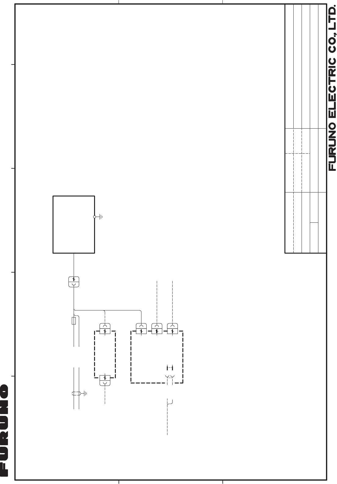
,17(5&211(&7,21 ',$*5$0
┦⤖⥺ᅗ
࣮ࣞࢲ࣮ࢭࣥࢧ࣮
5$'$5 6(1625
+0$.,
ὀグ
127(
㸨㸯㸧㐀⯪ᡤᡭ㓄ࠋ
㸨㸰㸧࢜ࣉࢩࣙࣥࠋ
6+,3<$5' 6833/<
237,21
5-/$1
࣮ࢧࢿࢵࢺࣁࣈ
5-
+8%
(7+(51(7 +8%
08/7, )81&7,21 ',63/$<
࣐ࣝࢳࣇࣥࢡࢩࣙࣥ
ࢹࢫࣉࣞ
25ࡲࡓࡣ
-81&7,21 %2;
7/&$7
ࢪࣙࣥࢺ࣎ࢵࢡࢫ
7=7%%
7=7/))
&& %
$XJ
$XJ
-
࢝
࢜
5('
%/8
)5836))0Pȭ
9'&
)5836))000P
✵୰⥺㒊
$17(11$ 81,7
56%
P
$'56$ ;&ODVV
,9VT
$'56$$ ;&ODVV
'56$$$ ;&ODVV
9'& 㺚㺹
㺖㺹
:+7
%/.
9+30996[&
P
08/7, )81&7,21 ',63/$<
࣐ࣝࢳࣇࣥࢡࢩࣙࣥࢹࢫࣉࣞ
ࢿࢵࢺ࣮࣡ࢡᶵჾ
1(7:25. (48,30(17
7=7%%7=7/))
02'=P
673 &$%/(
3/Aug/2016 H.MAKI
S-1
FURUNO Worldwide Warranty for Pleasure Boats (Except North America)
This warranty is valid for products manufactured by Furuno
Electric Co. (hereafter FURUNO) and installed on a pleasure
boat. Any web based purchases that are imported into other
countries by anyone other than a FURUNO certified dealer may
not comply with local standards. FURUNO strongly recommends
against importing these products from international websites as
the imported product may not work correctly and may interfere
with other electronic devices. The imported product may also be
in breach of the local laws and mandated technical requirements.
Products imported into other countries as described previously
shall not be eligible for local warranty service.
For products purchased outside of your country please contact
the national distributor of Furuno products in the country where
purchased.
This warranty is in addition to the customer´s statutory legal
rights.
1. Terms and Conditions of Warranty
FURUNO guarantees that each new FURUNO product is the
result of quality materials and workmanship. The warranty is
valid for a period of 2 years (24 months) from the date of the
invoice, or the date of commissioning of the product by the
installing certified dealer.
2. FURUNO Standard Warranty
The FURUNO standard warranty covers spare parts and labour
costs associated with a warranty claim, provided that the product
is returned to a FURUNO national distributor by prepaid carrier.
The FURUNO standard warranty includes:
Repair at a FURUNO national distributor
All spare parts for the repair
Cost for economical shipment to customer
3. FURUNO Onboard Warranty
If the product was installed/commissioned and registered by a
certified FURUNO dealer, the customer has the right to the
onboard warranty.
The FURUNO onboard warranty includes
• Free shipping of the necessary parts
• Labour: Normal working hours only
• Travel time: Up to a maximum of two (2) hours
• Travel distance: Up to a maximum of one hundred
and sixty (160) KM by car for the complete journey
4. Warranty Registration
For the Standard Warranty - presentation of product with serial
number (8 digits serial number, 1234-5678) is sufficient.
Otherwise, the invoice with serial number, name and stamp of
the dealer and date of purchase is shown.
For the Onboard Warranty your FURUNO certified dealer will
take care of all registrations.
5. Warranty Claims
For the Standard Warranty - simply send the defective product
together with the invoice to a FURUNO national distributor.
For the Onboard Warranty – contact a FURUNO national
distributor or a certified dealer. Give the product´s serial number
and describe the problem as accurately as possible.
Warranty repairs carried out by companies/persons other than a
FURUNO national distributor or a certified dealer is not covered
by this warranty.
6. Warranty Limitations
When a claim is made, FURUNO has a right to choose whether
to repair the product or replace it.
The FURUNO warranty is only valid if the product was correctly
installed and used. Therefore, it is necessary for the customer to
comply with the instructions in the handbook. Problems which
result from not complying with the instruction manual are not
covered by the warranty.
FURUNO is not liable for any damage caused to the vessel by
using a FURUNO product.
The following are excluded from this warranty:
a. Second-hand product
b. Underwater unit such as transducer and hull unit
c. Routine maintenance, alignment and calibration
services.
d. Replacement of consumable parts such as fuses,
lamps, recording papers, drive belts, cables, protective
covers and batteries.
e. Magnetron and MIC with more than 1000 transmitting
hours or older than 12 months, whichever comes first.
f. Costs associated with the replacement of a transducer
(e.g. Crane, docking or diver etc.).
g. Sea trial, test and evaluation or other demonstrations.
h. Products repaired or altered by anyone other than the
FURUNO national distributor or an authorized dealer.
i. Products on which the serial number is altered,
defaced or removed.
j. Problems resulting from an accident, negligence,
misuse, improper installation, vandalism or water
penetration.
k. Damage resulting from a force majeure or other natural
catastrophe or calamity.
l. Damage from shipping or transit.
m. Software updates, except when deemed necessary
and warrantable by FURUNO.
n. Overtime, extra labour outside of normal hours such as
weekend/holiday, and travel costs above the 160 KM
allowance
o. Operator familiarization and orientation.
FURUNO Electric Company, March 1, 2011

FURUNO Warranty for North America
FURUNO U.S.A., Limited Warranty provides a twenty-four (24) months LABOR and twenty-four (24) months PARTS
warranty on products from the date of installation or purchase by the original owner. Products or components that are
represented as being waterproof are guaranteed to be waterproof only for, and within the limits, of the warranty
period stated above. The warranty start date may not exceed eighteen (18) months from the original date of purchase
by dealer from Furuno USA and applies to new equipment installed and operated in accordance with Furuno USA’s
published instructions.
Magnetrons and Microwave devices will be warranted for a period of 12 months from date of original equipment
installation.
Furuno U.S.A., Inc. warrants each new product to be of sound material and workmanship and through its authorized
dealer will exchange any parts proven to be defective in material or workmanship under normal use at no charge for a
period of 24 months from the date of installation or purchase.
Furuno U.S.A., Inc., through an authorized Furuno dealer will provide labor at no cost to replace defective parts,
exclusive of routine maintenance or normal adjustments, for a period of 24 months from installation date provided the
work is done by Furuno U.S.A., Inc. or an AUTHORIZED Furuno dealer during normal shop hours and within a radius
of 50 miles of the shop location.
A suitable proof of purchase showing date of purchase, or installation certification must be available to Furuno U.S.A.,
Inc., or its authorized dealer at the time of request for warranty service.
This warranty is valid for installation of products manufactured by Furuno Electric Co. (hereafter FURUNO). Any
purchases from brick and mortar or web-based resellers that are imported into other countries by anyone other than a
FURUNO certified dealer, agent or subsidiary may not comply with local standards. FURUNO strongly recommends
against importing these products from international websites or other resellers, as the imported product may not work
correctly and may interfere with other electronic devices. The imported product may also be in breach of the local
laws and mandated technical requirements. Products imported into other countries, as described previously, shall not
be eligible for local warranty service.
For products purchased outside of your country please contact the national distributor of Furuno products in the
country where purchased.
WARRANTY REGISTRATION AND INFORMATION
To register your product for warranty, as well as see the complete warranty guidelines and limitations, please visit
www.furunousa.com and click on “Support”. In order to expedite repairs, warranty service on Furuno equipment is
provided through its authorized dealer network. If this is not possible or practical, please contact Furuno U.S.A., Inc.
to arrange warranty service.
FURUNO U.S.A., INC.
Attention: Service Coordinator
4400 N.W. Pacific Rim Boulevard
Camas, WA 98607-9408
Telephone: (360) 834-9300
FAX: (360) 834-9400
Furuno U.S.A., Inc. is proud to supply you with the highest quality in Marine Electronics. We know you had several
choices when making your selection of equipment, and from everyone at Furuno we thank you. Furuno takes great
pride in customer service.
Declaration of Conformit
y
[DRS6A X-Class/DRS12A X-Class/DRS25A X-Class]
Bulgarian
(
BG
)
Spanish
(
ES
)
Czech
(
CS
)
Danish
(
DA
)
German
(
DE
)
Estonian
(
ET
)
Greek
(
EL
)
English
(
EN
)
French
(
FR
)
Croatian
(
HR
)
Italian
(
IT
)
Latvian
(
LV
)
ELi vastavusdeklaratsiooni täielik tekst on kättesaadav järgmisel
internetiaadressil:
С настоящото Furuno Electric Co., Ltd. декларира, че гореспоменат тип
радиосъоръжение е в съответствие с Директива 2014/53/ЕС.
Цялостният текст на ЕС декларацията за съответствие може да се намери
на следния интернет адрес:
Por la presente, Furuno Electric Co., Ltd. declara que el tipo de equipo
radioeléctrico arriba mencionado es conforme con la Directiva 2014/53/UE.
El texto completo de la declaración UE de conformidad está disponible en la
dirección Internet siguiente:
Tímto Furuno Electric Co., Ltd. prohlašuje, že výše zmíněné typ rádiového
zařízení je v souladu se směrnicí 2014/53/EU.
Úplné znění EU prohlášení o shodě je k dispozici na této internetové adrese:
Hermed erklærer Furuno Electric Co., Ltd., at ovennævnte radioudstyr er i
overensstemmelse med direktiv 2014/53/EU.
EU-overensstemmelseserklæringens fulde tekst kan findes på følgende
internetadresse:
Hiermit erklärt die Furuno Electric Co., Ltd., dass der oben genannte
Funkanlagentyp der Richtlinie 2014/53/EU entspricht.
Der vollständige Text der EU-Konformitätserklärung ist unter der folgenden
Internetadresse verfügbar:
Käesolevaga deklareerib Furuno Electric Co., Ltd., et ülalmainitud raadioseadme
tüü
p
vastab direktiivi 2014/53/EL nõuetele.
Pilns ES atbilstības deklarācijas teksts ir pieejams šādā interneta vietnē:
Με την παρούσα η Furuno Electric Co., Ltd., δηλώνει ότι ο προαναφερθέντας
ραδιοεξοπλισμός πληροί την οδηγία 2014/53/ΕΕ.
Το πλήρες κείμενο της δήλωσης συμμόρφωσης ΕΕ διατίθεται στην ακόλουθη
ιστοσελίδα στο διαδίκτυο:
Hereby, Furuno Electric Co., Ltd. declares that the above-mentioned radio
e
q
ui
p
ment t
yp
e is in com
p
liance with Directive 2014/53/EU.
The full text of the EU declaration of conformity is available at the following
internet address:
Le soussigné, Furuno Electric Co., Ltd., déclare que l'équipement radioélectrique
du type mentionné ci-dessusest conforme à la directive 2014/53/UE.
Le texte complet de la déclaration UE de conformité est disponible à l'adresse
internet suivante:
Furuno Electric Co., Ltd. ovime izjavljuje da je gore rečeno radijska oprema tipa
u skladu s Direktivom 2014/53/EU.
Cjeloviti tekst EU izjave o sukladnosti dostupan je na sljedećoj internetskoj
adresi:
Il fabbricante, Furuno Electric Co., Ltd., dichiara che il tipo di apparecchiatura
radio menzionato so
p
ra è conforme alla direttiva 2014/53/UE.
Il testo completo della dichiarazione di conformità UE è disponibile al seguente
indirizzo Internet:
Ar šo Furuno Electric Co., Ltd. deklarē, ka augstāk minēts radioiekārta atbilst
Direktīvai 2014/53/ES.
Lithuanian
(
LT
)
Hungarian
(
HU
)
Maltese
(
MT
)
Dutch
(
NL
)
Polish
(
PL
)
Portuguese
(PT)
Romanian
(
RO
)
Slovak
(S
K
)
Slovenian
(S
L
)
Finnish
(
FI
)
Swedish
(
SV
)
Online Resource
http://www.furuno.com/en/support/red_doc
O texto integral da declaração de conformidade está disponível no seguinte
endereço de Internet:
Aš, Furuno Electric Co., Ltd., patvirtinu, kad pirmiau minėta radijo įrenginių tipas
atitinka Direkt
y
v
ą
2014/53/ES.
Visas ES atitikties deklaracijos tekstas prieinamas šiuo interneto adresu:
Furuno Electric Co., Ltd. igazolja, hogy fent említett típusú rádióberendezés
megfelel a 2014/53/EU irányelvnek.
Az EU-megfelelőségi nyilatkozat teljes szövege elérhető a következő internetes
címen:
B'dan, Furuno Electric Co., Ltd., niddikjara li msemmija hawn fuq-tip ta' tagħmir
tar-radju huwa konformi mad-Direttiva 2014/53/UE.
It-test kollu tad-dikjarazzjoni ta' konformità tal-UE huwa disponibbli f'dan l-indirizz
tal-Internet li ġej:
Hierbij verklaar ik, Furuno Electric Co., Ltd., dat het hierboven genoemde type
radioa
pp
aratuur conform is met Richtli
j
n 2014/53/EU.
De volledige tekst van de EU-conformiteitsverklaring kan worden geraadpleegd
o
p
het vol
g
ende internetadres:
Furuno Electric Co., Ltd. niniejszym oświadcza, że wyżej wymieniony typ
urz
ą
dzenia radiowe
g
o
j
est z
g
odn
y
z d
y
rekt
y
w
ą
2014/53/UE
.
Pełny tekst deklaracji zgodności UE jest dostępny pod następującym adresem
internetow
y
m:
O(a) abaixo assinado(a) Furuno Electric Co., Ltd. declara que o mencionado
acima tipo de equipamento de rádio está em conformidade com a Diretiva
2014/53/UE.
Furuno Electric Co., Ltd. vakuuttaa, että yllä mainittu radiolaitetyyppi on
direktiivin 2014/53/EU mukainen.
EU-vaatimustenmukaisuusvakuutuksen täysimittainen teksti on saatavilla
seuraavassa internetosoitteessa:
Härmed försäkrar Furuno Electric Co., Ltd. att ovan nämnda typ av
radioutrustning överensstämmer med direktiv 2014/53/EU.
Den fullständiga texten till EU-försäkran om överensstämmelse finns på
följande webbadress:
Prin prezenta, Furuno Electric Co., Ltd. declară că menționat mai sus tipul de
echipamente radio este în conformitate cu Directiva 2014/53/UE.
Textul integral al declarației UE de conformitate este disponibil la următoarea
adresă internet:
Furuno Electric Co., Ltd. týmto vyhlasuje, že vyššie spomínané rádiové
zariadenie t
yp
u
j
e v súlade so smernicou 2014/53/EÚ.
Úplné EÚ vyhlásenie o zhode je k dispozícii na tejto internetovej adrese:
Furuno Electric Co., Ltd. potrjuje, da je zgoraj omenjeno tip radijske opreme
skladen z Direktivo 2014/53/EU.
Celotno besedilo izjave EU o skladnosti je na voljo na naslednjem spletnem
naslovu:

Pub. No. IME-36460-A3
A : DEC. 2015
A3 : SEP 21, 2016