Furuno USA 9ZWRTR115 Transceiver for Radar User Manual IME 36490 A
Furuno USA Inc Transceiver for Radar IME 36490 A
UserManual.wiki
>
Furuno USA
>
9ZWRTR115 User Manual
User Manual
Navigation menu
Upload a User Manual
Namespaces
Wiki Guide
HTML
PDF
Info
Views
User Manual
Discussion / Help
Navigation
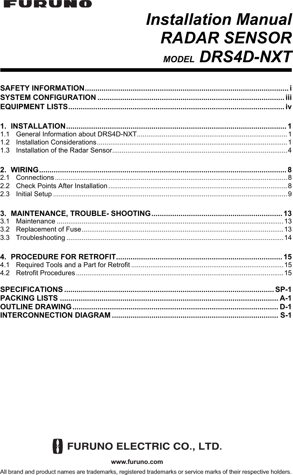
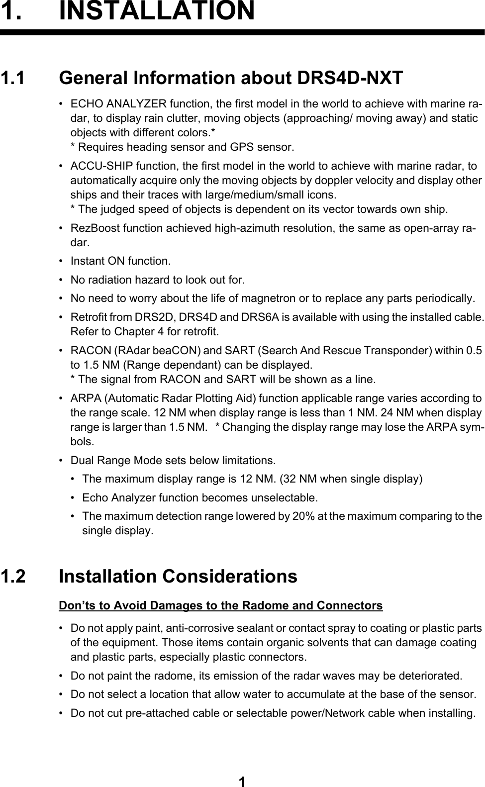
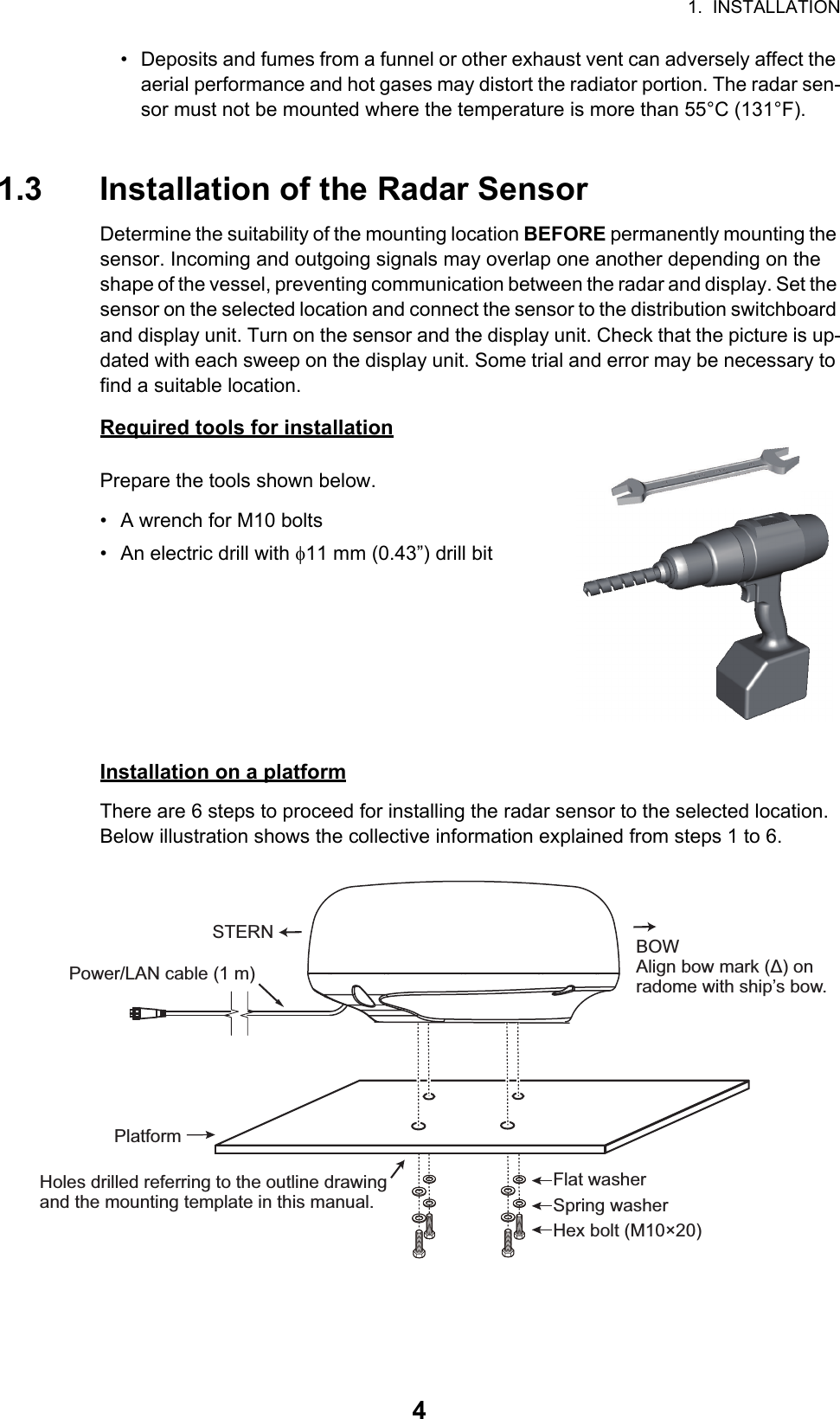
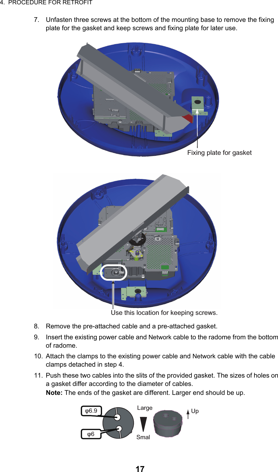
![2. WIRING92.3 Initial SetupTurn on the multi function display device, and do the initial setup for the antenna unit.2.3.1 Initial setup for NavNet TZtouch2 (TZTL12F/TZTL15F)1. Tap the [Home] icon to show the home screen and display mode settings.2. Tap [Radar] from the [Settings] menu.3. Tap [Radar Source], then select the appropriate antenna unit.Note: If an antenna unit is connected but does not appear in the [Radar Source] list, close the list and open it again. The name of the antenna unit should appear with a check mark, as in the example below.4. Drag the [Radar] menu display the menu item [Radar Initial Setup], then tap [Radar Initial Setup].5. Referring to the tables below, set up the radar.[Radar] menu - [Radar Initial Setup][Radar] menu - [Antenna Position]Menu item Description[Antenna Rotation] Select the speed of antenna rotation.[Antenna Heading Align] See "How to align the antenna heading" on page 10.[Main Bang Suppression] If main bang appears at the screen center, slide the circle icon so that the main bang disappears, while watching the radar echo at the left-hand side of the display.[Enable Sector Blanking] Up to two sectors may be selected for blanking (no trans-mission). Select [ON] to enable this feature. Set the start and end angles (0° to 359°).[Enable Sector 2 Blanking]Menu item Description[Longitudinal (from bow)] Referring to the figure on the right, enter the radar antenna positioning bow-stern (Longi-tudinal) and port-starboard (Lateral) position from the origin.[Lateral (-Port)][Antenna Height] Select the height of the antenna above the waterline.[Radar Monitoring] Display various information regarding the connected ra-dar.[ARPA Advanced Settings] Do not change these settings.[Set Hardware To Factory Default]Resets the radar selected at [Radar Source] to factory default.[Reset Default Settings] Resets [Radar] menu settings to default.xxxxxxxx-xxxxxxxxxxOriginOrigin](https://usermanual.wiki/Furuno-USA/9ZWRTR115/User-Guide-2821037-Page-14.png)
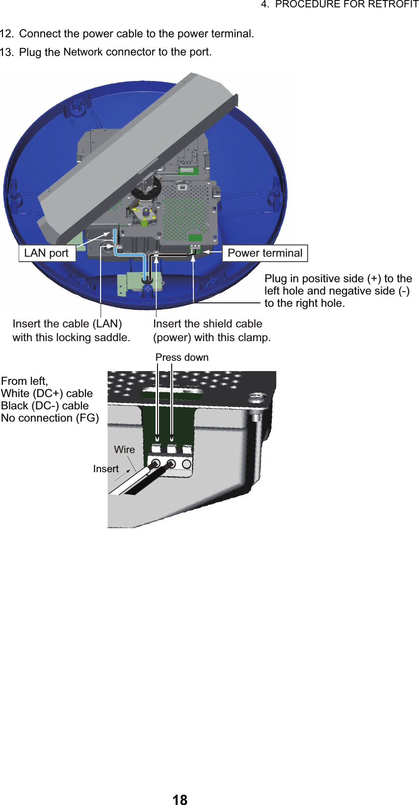
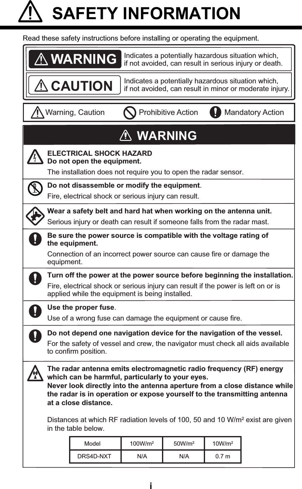
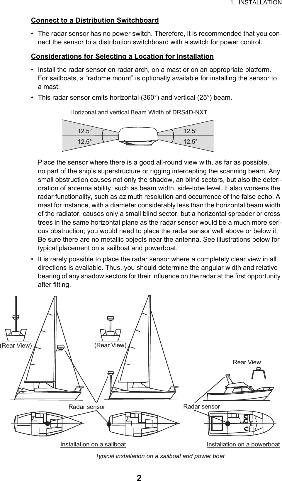
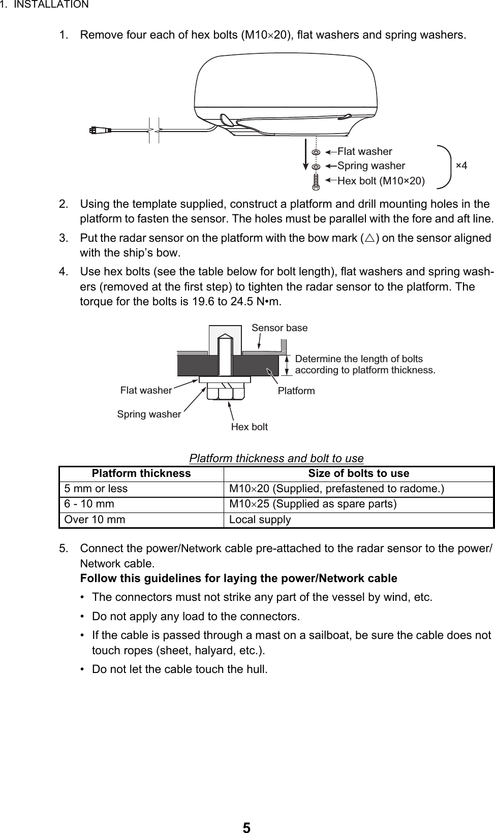
![2. WIRING10How to align the antenna headingYou have mounted the antenna unit facing straight ahead in the direction of the bow. Therefore, a small but conspicuous target dead ahead visually should appear on the heading line (zero degrees). In practice, you will probably observe some small bearing error on the display because of the difficulty in achieving accurate initial positioning of the antenna unit. The follow-ing adjustment will compensate for the error.1. Set your radar with 0.125 and 0.25 NM range and the head up mode.You can select a range by using the pinch action. The range appears at the bottom right of the screen. Range may also be selected using the slide bar displayed on the right-hand side of the radar display area. Drag the bar up to zoom in, or down to zoom out.2. Turn the vessel’s bow toward a target.3. Tap the [Home] icon to show the home screen and display mode settings.4. Tap [Radar] to show the [Radar] menu. 5. Drag the [Radar] menu to show the [RADAR INITAL SETUP] menu.6. Tap [Antenna Heading Align].7. Key in the offset value so that the target is displayed at the very top of the screen (setting range: +179.9° to -180°, +: clockwise direction, -: counterclockwise direc-tion), then tap the icon.8. Confirm that the target echo is displayed at correct bearing on the screen.2.3.2 Initial setup for NavNet TZtouch (TZT9/TZT14/TZTBB)1. Press the Home key (or tap the Home icon).2. Select [Menu] on the menu icon bar to open the main menu.3. Select [Radar].4. Select [Radar Source] on the [Menu Radar] sub menus, then select the radar type connected.Note: If a antenna unit is connected but does not appear in the [Radar Source] list, close the list and open it again. The name of the antenna unit should appear with a check mark, as in the example below.RangeIncrease rangeIncrease range Reduce rangeReduce rangeRadar indicationsHU NM Tx3.650](https://usermanual.wiki/Furuno-USA/9ZWRTR115/User-Guide-2821037-Page-15.png)
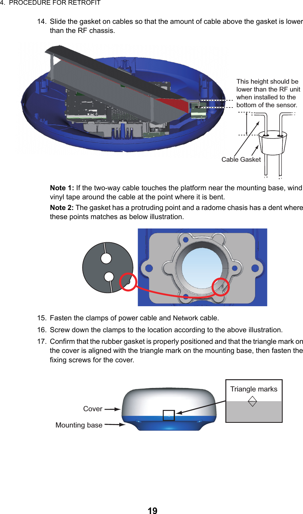
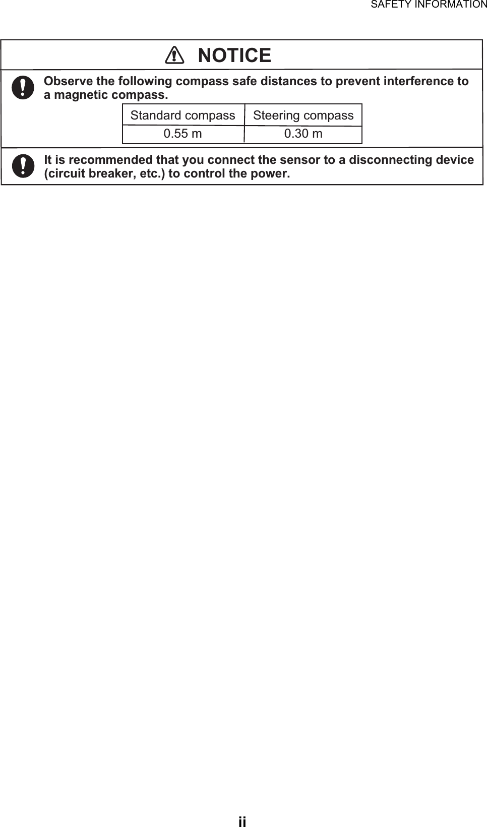
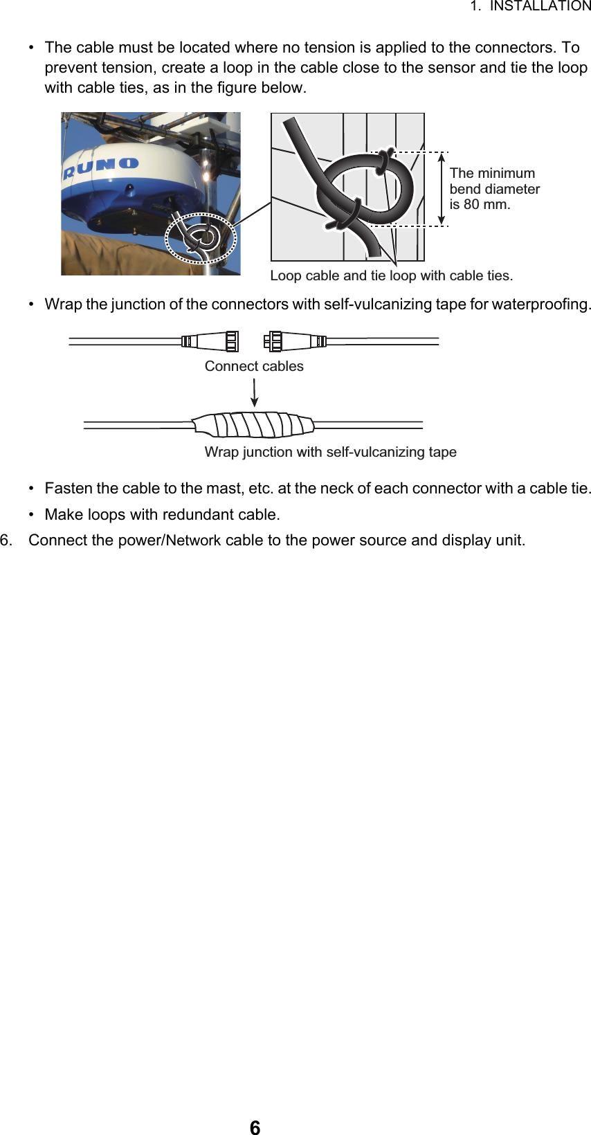
![2. WIRING115. Drag the [Menu Radar] sub menus to find the menu item [Radar Initial Setup]. Menu Radar (Radar Initial Setup)Menu item Description[Antenna Rotation] Select the speed of antenna rotation.[Antenna Heading Align]See the topic of "How to align the antenna heading" on page 2-12.[Main Bang Sup-pression]If main bang appears at the screen center, slide the circle icon so that the main bang disappears, while watching the radar echo at the left-hand side of the display.[Antenna Height] Select the height of the antenna above the waterline.[Antenna Longitu-dinal Position] Enter the antenna positioning bow-stern (Longitudi-nal) and port-starboard (lateral) position from the ori-gin.[Antenna Lateral Position (-Port)]Others See Operator’ Manual for TZT9/14/BB.xxxxxxxx-xxxxxxxxxxxxxxxxxx-xxxxxxxxxxTitleOrigin](https://usermanual.wiki/Furuno-USA/9ZWRTR115/User-Guide-2821037-Page-16.png)
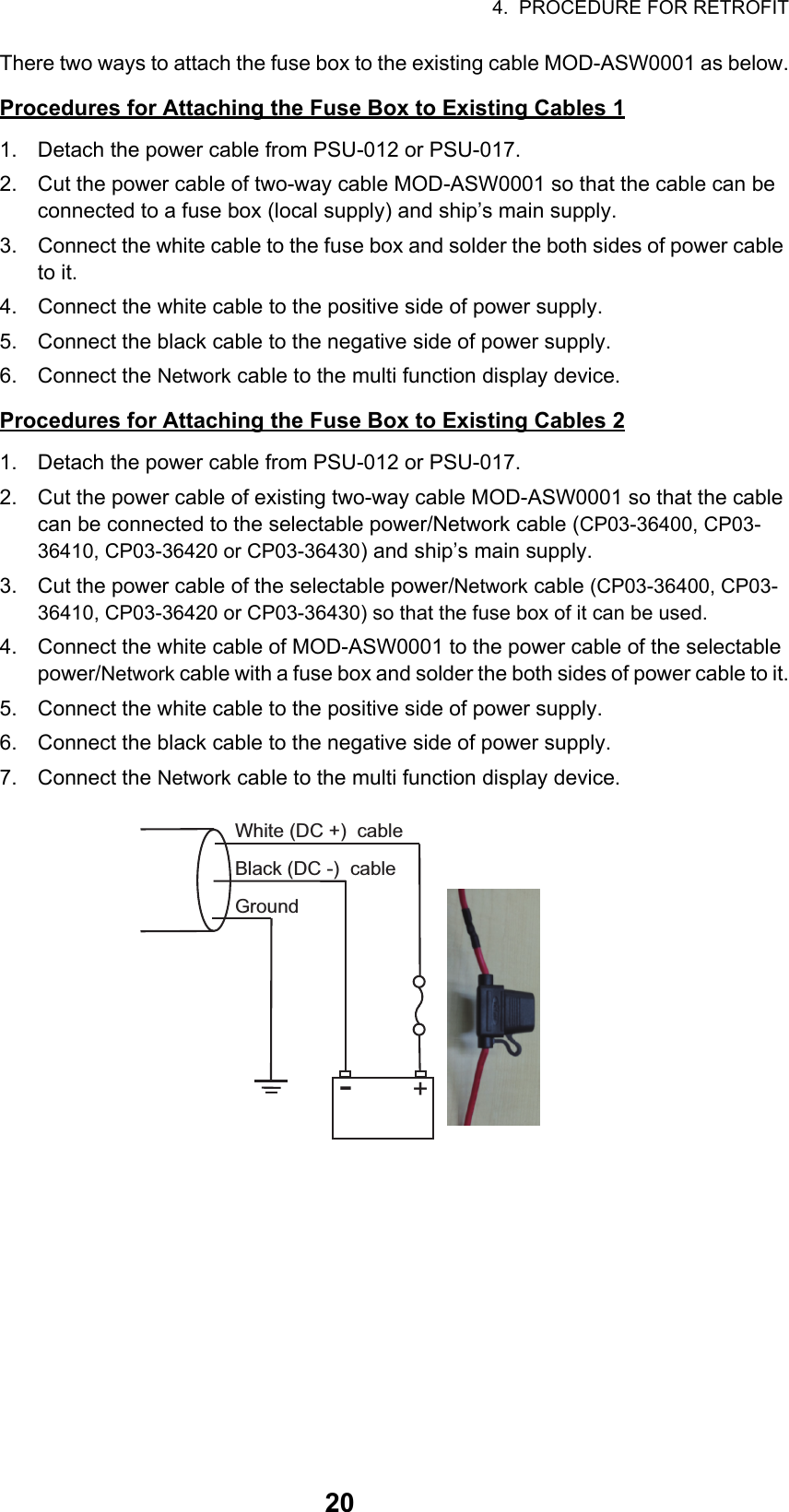
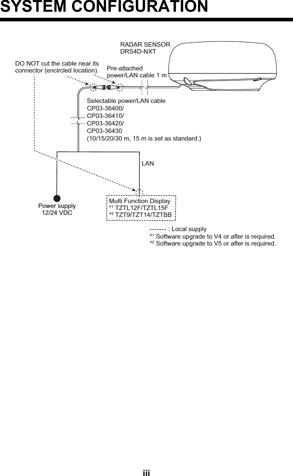
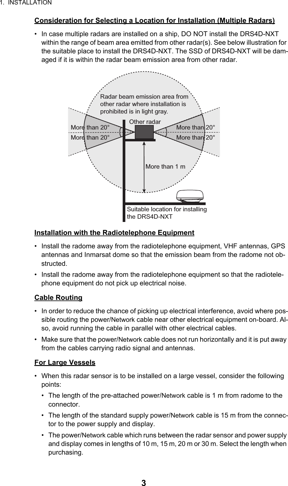
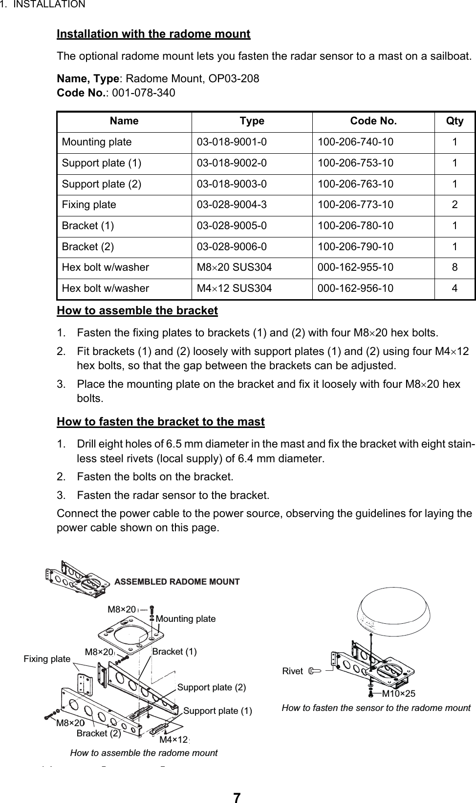
![2. WIRING12How to align the antenna headingYou have mounted the antenna unit facing straight ahead in the direction of the bow. Therefore, a small but conspicuous target dead ahead visually should ap-pear on the heading line (zero degrees). In practice, you will probably observe some small bearing error on the display be-cause of the difficulty in achieving accurate initial positioning of the antenna unit. The following adjustment will compensate for the error.1) Select a range between 0.125 and 0.25 NM and set the mode to “head up“.You can select a range by a pinch action. The range and range ring interval appear at the bottom left of the screen.For TZTBB, you can also control the range in the operation as follows. Tap the radar scale box at the bottom left-hand corner of the screen to display the slider bar. Drag the circle icon to set the range scale.2) Turn the vessel’s bow toward a target.3) Press the Home key (or tap the Home icon), then select [Menu] icon, [Radar], and [Antenna Heading Align] in that order to show the numeric software key-board.4) Key in the offset value so that the target is at the very top of the screen (setting range: +/- 0° to 180°, +: clockwise direction, -: counterclockwise direction), then tap [Save].5) Confirm that the target echo is displayed at correct bearing on the screen.1Range Range ring intervalRange indicationsZoom outZoom inPinch actionTap the area circled in the dashed line to display the slider bar.Note: You can switch between transmit and stand-by by tapping the right side of the radar scale box.Drag the circle icon to set the range scale.Slider barZoom inZoom out4NMCurrent range](https://usermanual.wiki/Furuno-USA/9ZWRTR115/User-Guide-2821037-Page-17.png)