Furuno USA 9ZWRTR115 Transceiver for Radar User Manual IME 36490 A
Furuno USA Inc Transceiver for Radar IME 36490 A
User Manual

www.furuno.com
A
ll brand and product names are trademarks, registered trademarks or service marks of their respective holders.
Installation Manual
RADAR SENSOR
MODEL DRS4D-NXT
SAFETY INFORMATION.................................................................................................. i
SYSTEM CONFIGURATION .......................................................................................... iii
EQUIPMENT LISTS........................................................................................................ iv
1. INSTALLATION.......................................................................................................... 1
1.1 General Information about DRS4D-NXT...............................................................................1
1.2 Installation Considerations....................................................................................................1
1.3 Installation of the Radar Sensor............................................................................................4
2. WIRING....................................................................................................................... 8
2.1 Connections .......................................................................................................................... 8
2.2 Check Points After Installation ..............................................................................................8
2.3 Initial Setup ...........................................................................................................................9
3. MAINTENANCE, TROUBLE- SHOOTING............................................................... 13
3.1 Maintenance .......................................................................................................................13
3.2 Replacement of Fuse..........................................................................................................13
3.3 Troubleshooting ..................................................................................................................14
4. PROCEDURE FOR RETROFIT................................................................................ 15
4.1 Required Tools and a Part for Retrofit ................................................................................15
4.2 Retrofit Procedures.............................................................................................................15
SPECIFICATIONS ..................................................................................................... SP-1
PACKING LISTS ......................................................................................................... A-1
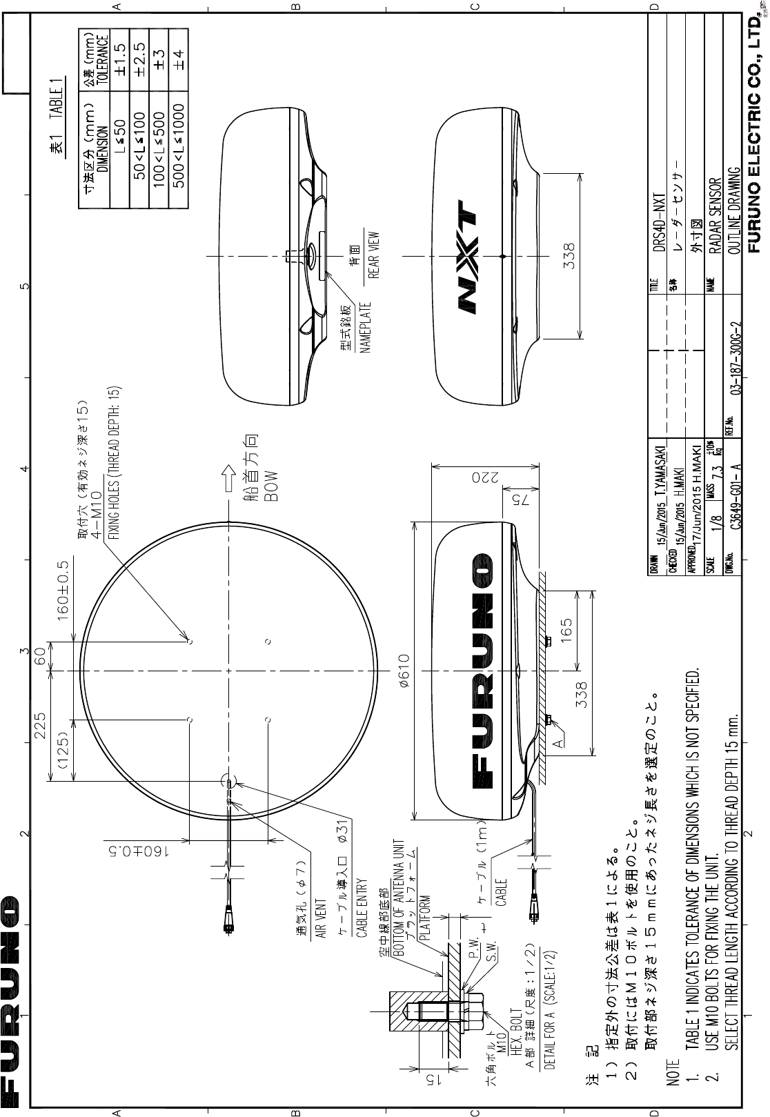
OUTLINE DRAWING................................................................................................... D-1
INTERCONNECTION DIAGRAM ................................................................................ S-1
i
SAFETY INFORMATION
Read these safety instructions before installing or operating the equipment.
WARNING
Indicates a potentially hazardous situation which,
if not avoided, can result in minor or moderate injury.
Warning, Caution Prohibitive Action
CAUTION
Mandatory Action
Indicates a potentially hazardous situation which,
if not avoided, can result in serious injury or death.
Wear a safety belt and hard hat when working on the antenna unit.
Serious injury or death can result if someone falls from the radar mast.
ELECTRICAL SHOCK HAZARD
Do not open the equipment.
The installation does not require you to open the radar sensor.
Be sure the power source is compatible with the voltage rating of
the equipment.
Connection of an incorrect power source can cause fire or damage the
equipment.
Turn off the power at the power source before beginning the installation.
Fire, electrical shock or serious injury can result if the power is left on or is
applied while the equipment is being installed.
WARNING
Do not disassemble or modify the equipment.
Fire, electrical shock or serious injury can result.
Use the proper fuse.
Use of a wrong fuse can damage the equipment or cause fire.
Do not depend one navigation device for the navigation of the vessel.
For the safety of vessel and crew, the navigator must check all aids available
to confirm position.
The radar antenna emits electromagnetic radio frequency (RF) energy
which can be harmful, particularly to your eyes.
Never look directly into the antenna aperture from a close distance while
the radar is in operation or expose yourself to the transmitting antenna
at a close distance.
Distances at which RF radiation levels of 100, 50 and 10 W/m
2
exist are given
in the table below.
100W/m
2
10W/m
2
Model
DRS4D-NXT N/A 0.7 m
50W/m
2
N/A
SAFETY INFORMATION
ii
NOTICE
It is recommended that you connect the sensor to a disconnecting device
(circuit breaker, etc.) to control the power.
Observe the following compass safe distances to prevent interference to
a magnetic compass.
Standard compass Steering compass
0.55 m 0.30 m
iii
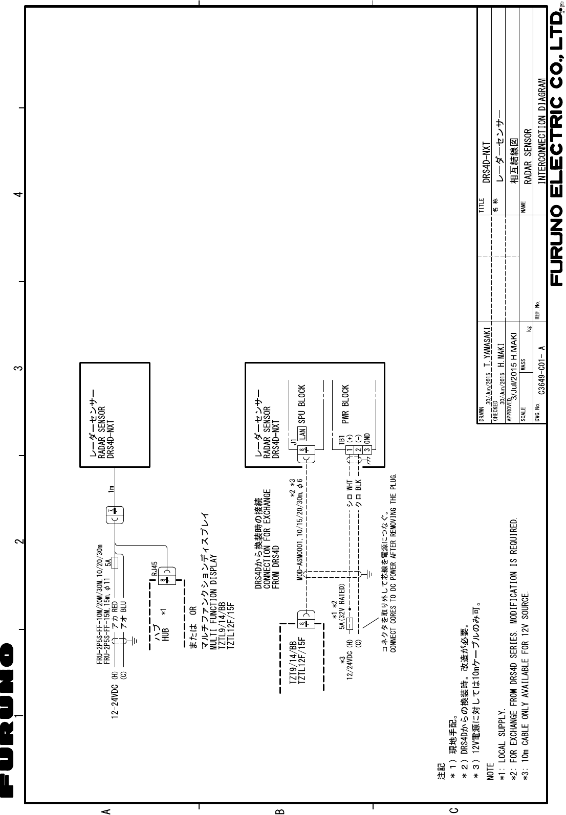
SYSTEM CONFIGURATION
Power supply
12/24 VDC
RADAR SENSOR
DRS4D-NXT
Multi Function Display
*1 TZTL12F/TZTL15F
*2 TZT9/TZT14/TZTBB
LAN
Pre-attached
power/LAN cable 1 m
: Local supply
*1 Software upgrade to V4 or after is required.
*2 Software upgrade to V5 or after is required.
Selectable power/LAN cable
CP03-36400/
CP03-36410/
CP03-36420/
CP03-36430
(10/15/20/30 m, 15 m is set as standard.)
DO NOT cut the cable near its
connector (encircled location).
iv
EQUIPMENT LISTS
Standard supply
Optional supply
Optional supply for Retrofit from DRS2D, DRS4D and DRS6A
Name Type Code No. Qty Remarks
Radar Sensor RSB-135 000-027-200 1
Installation Materials CP03-35701 001-295-920 1
CP03-36400 000-027-211 Select
one
Power/Network cable 10 m
CP03-36410 000-027-212 Power/Network cable 15 m
CP03-36420 000-027-213 Power/Network cable 20 m
CP03-36430 000-027-214 Power/Network cable 30 m
Spare Parts SP03-17901 001-351-470 1 Fuses
Name Type Code No. Qty Remarks
Radome Mount OP03-208 001-078-340 1
Name Type Code No. Qty Remarks
Gland Bush 03-174-3205-1 100-340-911-10 1
Clamp E0806A 000-166-489-10 1 For power cable
Simplified Installation Manual for
Retrofit
C32-01501 000-191-116 1

1
1. INSTALLATION
1.1 General Information about DRS4D-NXT
• ECHO ANALYZER function, the first model in the world to achieve with marine ra-
dar, to display rain clutter, moving objects (approaching/ moving away) and static
objects with different colors.*
* Requires heading sensor and GPS sensor.
• ACCU-SHIP function, the first model in the world to achieve with marine radar, to
automatically acquire only the moving objects by doppler velocity and display other
ships and their traces with large/medium/small icons.
* The judged speed of objects is dependent on its vector towards own ship.
• RezBoost function achieved high-azimuth resolution, the same as open-array ra-
dar.
• Instant ON function.
• No radiation hazard to look out for.
• No need to worry about the life of magnetron or to replace any parts periodically.
• Retrofit from DRS2D, DRS4D and DRS6A is available with using the installed cable.
Refer to Chapter 4 for retrofit.
• RACON (RAdar beaCON) and SART (Search And Rescue Transponder) within 0.5
to 1.5 NM (Range dependant) can be displayed.
* The signal from RACON and SART will be shown as a line.
• ARPA (Automatic Radar Plotting Aid) function applicable range varies according to
the range scale. 12 NM when display range is less than 1 NM. 24 NM when display
range is larger than 1.5 NM. * Changing the display range may lose the ARPA sym-
bols.
• Dual Range Mode sets below limitations.
• The maximum display range is 12 NM. (32 NM when single display)
• Echo Analyzer function becomes unselectable.
• The maximum detection range lowered by 20% at the maximum comparing to the
single display.
1.2 Installation Considerations
Don’ts to Avoid Damages to the Radome and Connectors
• Do not apply paint, anti-corrosive sealant or contact spray to coating or plastic parts
of the equipment. Those items contain organic solvents that can damage coating
and plastic parts, especially plastic connectors.
• Do not paint the radome, its emission of the radar waves may be deteriorated.
• Do not select a location that allow water to accumulate at the base of the sensor.
• Do not cut pre-attached cable or selectable power/Network cable when installing.
1. INSTALLATION
2
Connect to a Distribution Switchboard
• The radar sensor has no power switch. Therefore, it is recommended that you con-
nect the sensor to a distribution switchboard with a switch for power control.
Considerations for Selecting a Location for Installation
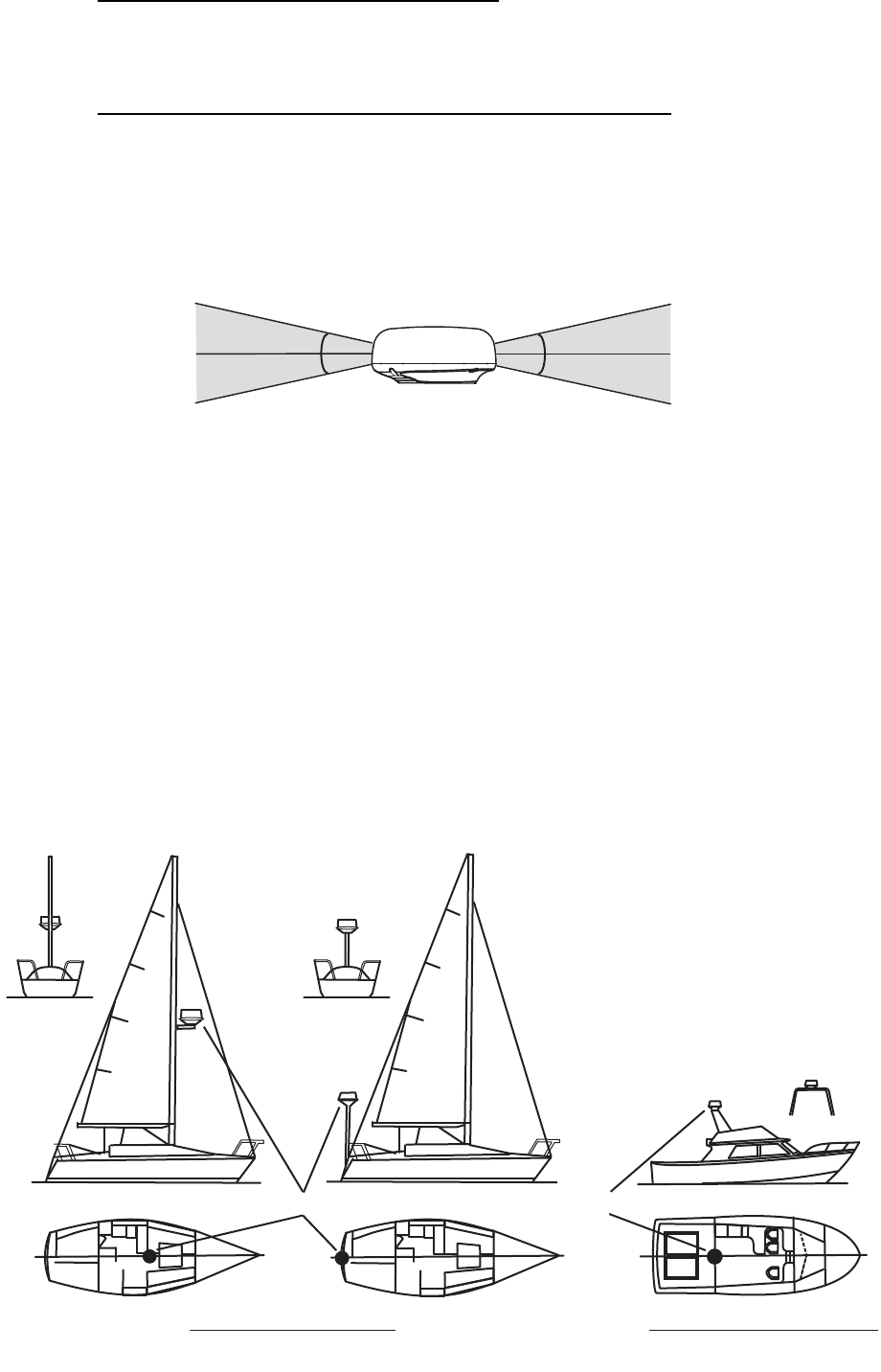
• Install the radar sensor on radar arch, on a mast or on an appropriate platform.
For sailboats, a “radome mount” is optionally available for installing the sensor to
a mast.
• This radar sensor emits horizontal (360°) and vertical (25°) beam.
Place the sensor where there is a good all-round view with, as far as possible,
no part of the ship’s superstructure or rigging intercepting the scanning beam. Any
small obstruction causes not only the shadow, an blind sectors, but also the deteri-
oration of antenna ability, such as beam width, side-lobe level. It also worsens the
radar functionality, such as azimuth resolution and occurrence of the false echo. A
mast for instance, with a diameter considerably less than the horizontal beam width
of the radiator, causes only a small blind sector, but a horizontal spreader or cross
trees in the same horizontal plane as the radar sensor would be a much more seri-
ous obstruction; you would need to place the radar sensor well above or below it.
Be sure there are no metallic objects near the antenna. See illustrations below for
typical placement on a sailboat and powerboat.
• It is rarely possible to place the radar sensor where a completely clear view in all
directions is available. Thus, you should determine the angular width and relative
bearing of any shadow sectors for their influence on the radar at the first opportunity
after fitting.
Horizonal and vertical Beam Width of DRS4D-NXT
12.5°
12.5°
12.5°
12.5°
Installation on a sailboat Installation on a powerboat
Typical installation on a sailboat and power boat
Radar sensorRadar sensorRadar sensor
Radar sensorRadar sensorRadar sensor
Rear View
(Rear View)
(Rear View)
1. INSTALLATION
3
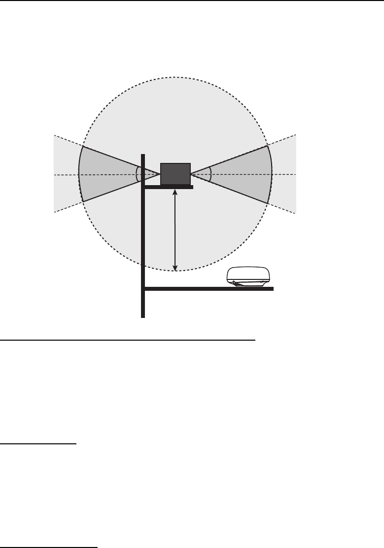
Consideration for Selecting a Location for Installation (Multiple Radars)
• In case multiple radars are installed on a ship, DO NOT install the DRS4D-NXT
within the range of beam area emitted from other radar(s). See below illustration for
the suitable place to install the DRS4D-NXT. The SSD of DRS4D-NXT will be dam-
aged if it is within the radar beam emission area from other radar.
Installation with the Radiotelephone Equipment
• Install the radome away from the radiotelephone equipment, VHF antennas, GPS
antennas and Inmarsat dome so that the emission beam from the radome not ob-
structed.
• Install the radome away from the radiotelephone equipment so that the radiotele-
phone equipment do not pick up electrical noise.
Cable Routing
• In order to reduce the chance of picking up electrical interference, avoid where pos-
sible routing the power/Network cable near other electrical equipment on-board. Al-
so, avoid running the cable in parallel with other electrical cables.
• Make sure that the power/Network cable does not run horizontally and it is put away
from the cables carrying radio signal and antennas.
For Large Vessels
• When this radar sensor is to be installed on a large vessel, consider the following
points:
• The length of the pre-attached power/Network cable is 1 m from radome to the
connector.
• The length of the standard supply power/Network cable is 15 m from the connec-
tor to the power supply and display.
• The power/Network cable which runs between the radar sensor and power supply
and display comes in lengths of 10 m, 15 m, 20 m or 30 m. Select the length when
purchasing.
More than 20°
More than 1 m
Other radar More than 20°
More than 20°
More than 20°
Suitable location for installing
the DRS4D-NXT
Radar beam emission area from
other radar where installation is
prohibited is in light gray.
1. INSTALLATION
4
• Deposits and fumes from a funnel or other exhaust vent can adversely affect the
aerial performance and hot gases may distort the radiator portion. The radar sen-
sor must not be mounted where the temperature is more than 55°C (131°F).
1.3 Installation of the Radar Sensor
Determine the suitability of the mounting location BEFORE permanently mounting the
sensor. Incoming and outgoing signals may overlap one another depending on the
shape of the vessel, preventing communication between the radar and display. Set the
sensor on the selected location and connect the sensor to the distribution switchboard
and display unit. Turn on the sensor and the display unit. Check that the picture is up-
dated with each sweep on the display unit. Some trial and error may be necessary to
find a suitable location.
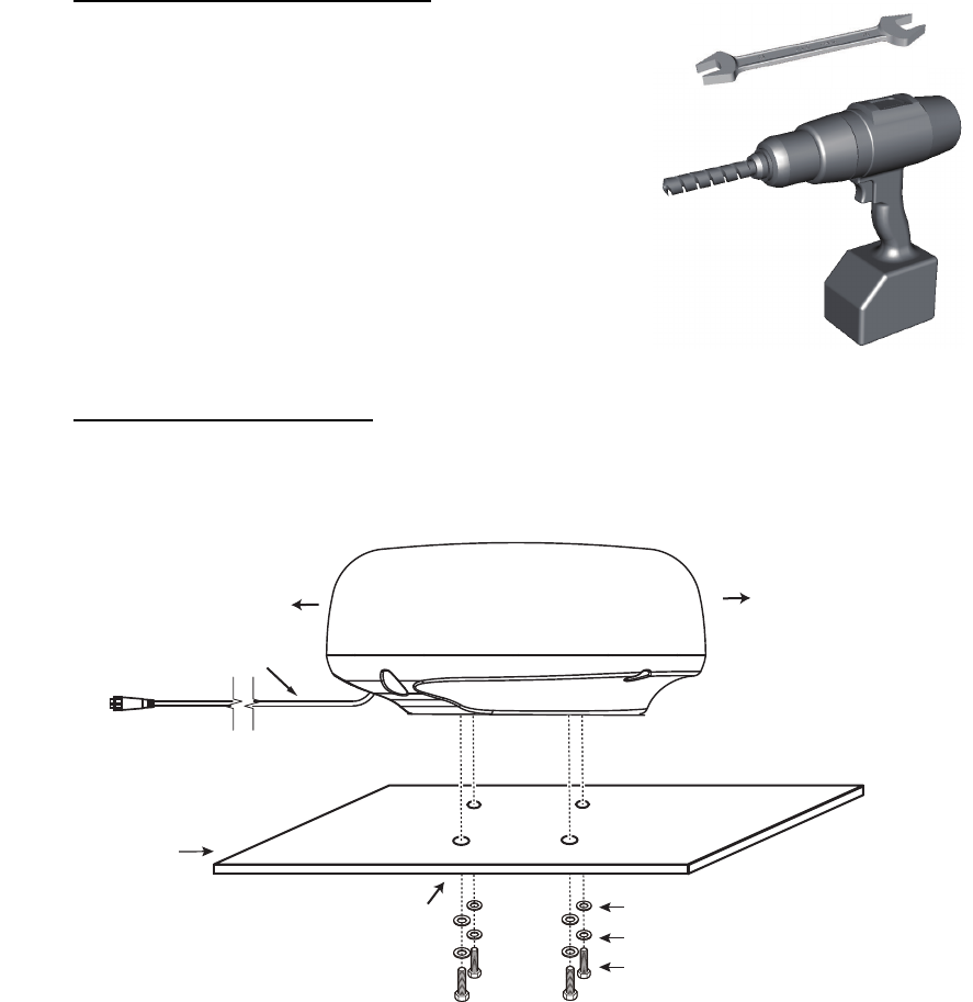
Required tools for installation
Prepare the tools shown below.
• A wrench for M10 bolts
• An electric drill with 11 mm (0.43”) drill bit
Installation on a platform
There are 6 steps to proceed for installing the radar sensor to the selected location.
Below illustration shows the collective information explained from steps 1 to 6.
STERN BOW
Align bow mark (Δ) on
radome with ship’s bow.
Power/LAN cable (1 m)
Holes drilled referring to the outline drawing
and the mounting template in this manual.
Platform
Hex bolt (M10×20)
Spring washer
Flat washer
1. INSTALLATION
5
1. Remove four each of hex bolts (M1020), flat washers and spring washers.
2. Using the template supplied, construct a platform and drill mounting holes in the
platform to fasten the sensor. The holes must be parallel with the fore and aft line.
3. Put the radar sensor on the platform with the bow mark () on the sensor aligned
with the ship’s bow.
4. Use hex bolts (see the table below for bolt length), flat washers and spring wash-
ers (removed at the first step) to tighten the radar sensor to the platform. The
torque for the bolts is 19.6 to 24.5 N•m.
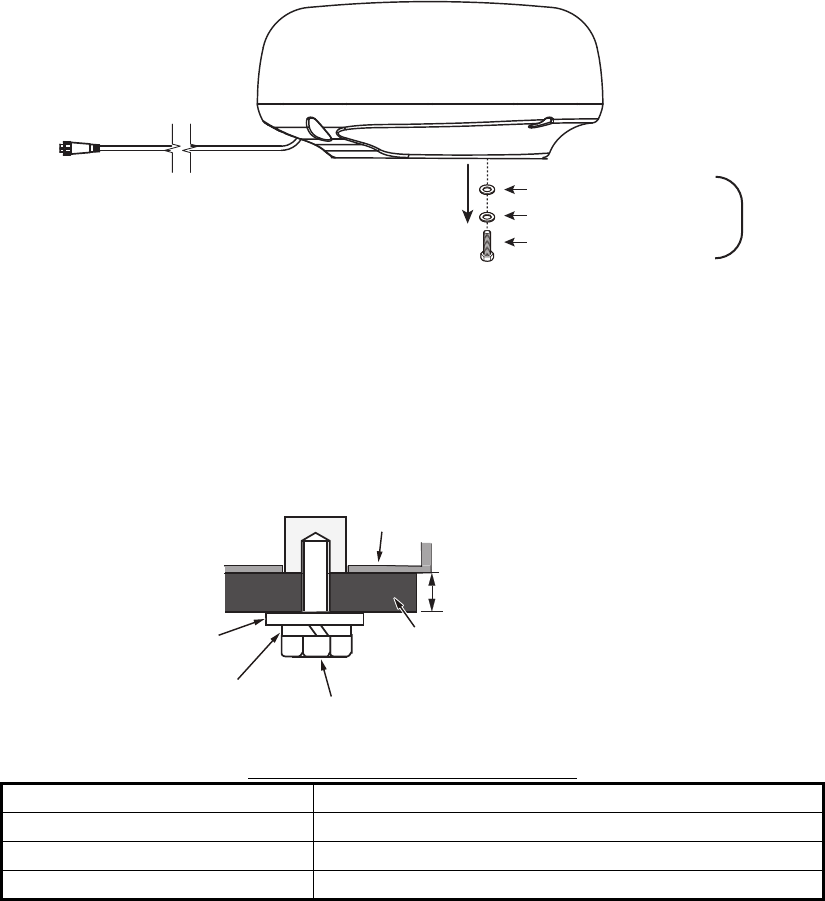
Platform thickness and bolt to use
5. Connect the power/Network cable pre-attached to the radar sensor to the power/
Network cable.
Follow this guidelines for laying the power/Network cable
• The connectors must not strike any part of the vessel by wind, etc.
• Do not apply any load to the connectors.
• If the cable is passed through a mast on a sailboat, be sure the cable does not
touch ropes (sheet, halyard, etc.).
• Do not let the cable touch the hull.
Platform thickness Size of bolts to use
5 mm or less M1020 (Supplied, prefastened to radome.)
6 - 10 mm M1025 (Supplied as spare parts)
Over 10 mm Local supply
Hex bolt (M10×20)
Spring washer
Flat washer
×4
Platform
Sensor base
Flat washer
Hex bolt
Spring washer
Determine the length of bolts
according to platform thickness.
1. INSTALLATION
6
• The cable must be located where no tension is applied to the connectors. To
prevent tension, create a loop in the cable close to the sensor and tie the loop
with cable ties, as in the figure below.
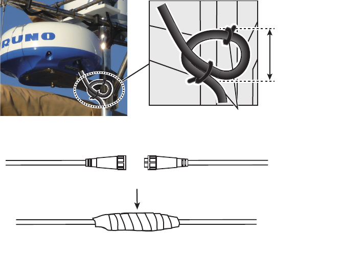
• Wrap the junction of the connectors with self-vulcanizing tape for waterproofing.
• Fasten the cable to the mast, etc. at the neck of each connector with a cable tie.
• Make loops with redundant cable.
6. Connect the power/Network cable to the power source and display unit.
Loop cable and tie loop with cable ties.
The minimum
bend diameter
is 80 mm.
Wrap junction with self-vulcanizing tape
Connect cables
1. INSTALLATION
7
Installation with the radome mount
The optional radome mount lets you fasten the radar sensor to a mast on a sailboat.
Name, Type: Radome Mount, OP03-208
Code No.: 001-078-340
How to assemble the bracket
1. Fasten the fixing plates to brackets (1) and (2) with four M820 hex bolts.
2. Fit brackets (1) and (2) loosely with support plates (1) and (2) using four M412
hex bolts, so that the gap between the brackets can be adjusted.
3. Place the mounting plate on the bracket and fix it loosely with four M820 hex
bolts.
How to fasten the bracket to the mast
1. Drill eight holes of 6.5 mm diameter in the mast and fix the bracket with eight stain-
less steel rivets (local supply) of 6.4 mm diameter.
2. Fasten the bolts on the bracket.
3. Fasten the radar sensor to the bracket.
Connect the power cable to the power source, observing the guidelines for laying the
power cable shown on this page.
Name Type Code No. Qty
Mounting plate 03-018-9001-0 100-206-740-10 1
Support plate (1) 03-018-9002-0 100-206-753-10 1
Support plate (2) 03-018-9003-0 100-206-763-10 1
Fixing plate 03-028-9004-3 100-206-773-10 2
Bracket (1) 03-028-9005-0 100-206-780-10 1
Bracket (2) 03-028-9006-0 100-206-790-10 1
Hex bolt w/washer M820 SUS304 000-162-955-10 8
Hex bolt w/washer M412 SUS304 000-162-956-10 4
Mounting plate
Support plate (1)
Support plate (2)
Bracket (1)
Fixing plate
M8×20
ASSEMBLED RADOME MOUNT
M8×20
M8×20
M4×12
M10×25
How to fasten the sensor to the radome mount
Bracket (2)
Rivet
How to assemble the radome mount

8
2. WIRING
2.1 Connections
2.1.1 Power Requirement
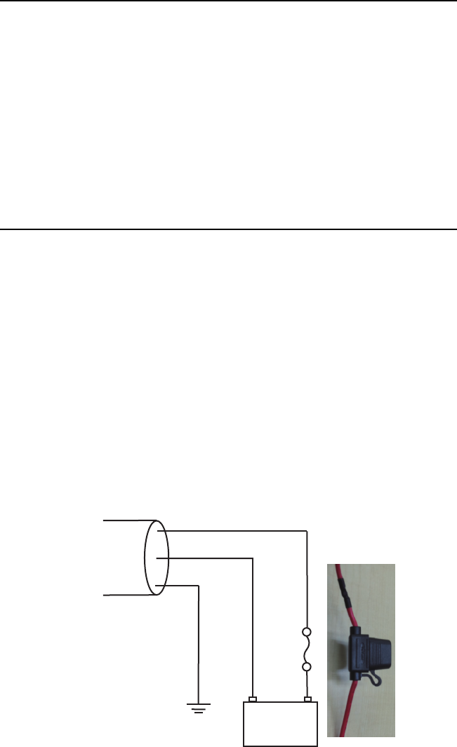
The DRS4D-NXT requires either 12 VDC or 24 VDC power. Connect the red cable to
the positive terminal of ship’s battery; the blue cable to the negative terminal. The
black cable is a shielding cable for grounding.
2.1.2 Network Cable Connection
Connect Network cable to the multi function display device*.
*Hereafter TZTL12F, TZTL15F, TZT9, TZT14 and TZTBB are referred to as “multi
function display device”.
2.2 Check Points After Installation
Before using the product, carry out the following:
• Mechanical checks
• Turning the power on and initial setup
Mechanical checks
Check below points before switching on the DRS4D-NXT.
• All washers are in place and bolts are fully tightened.
• All connections are secure and Network cable is connected to the multi function dis-
play device.
• All connecting cables and wires are secured as instructed in page 4.
Turning the power on and initial setup
Use the information in this manual and the manual for multi function display device to
power the sensor and to proceed with initial setup.
1. Ensure that all personnel are clear of antenna.
2. Press and hold down the power key of your multi function display device until the
unit is ON.
3. Take the appropriate action on your multi function display device to turn on the
DRS4D-NXT.
4. Check if the heading is correctly aligned - targets should appear at their correct
bearing relative to the boat’s bow. Adjust the alignment if necessary, referring to
section 2.3.
2. WIRING
9
2.3 Initial Setup
Turn on the multi function display device, and do the initial setup for the antenna unit.
2.3.1 Initial setup for NavNet TZtouch2 (TZTL12F/TZTL15F)
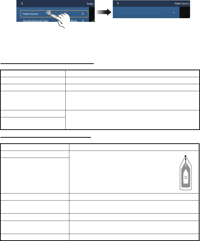
1. Tap the [Home] icon to show the home screen and display mode settings.
2. Tap [Radar] from the [Settings] menu.
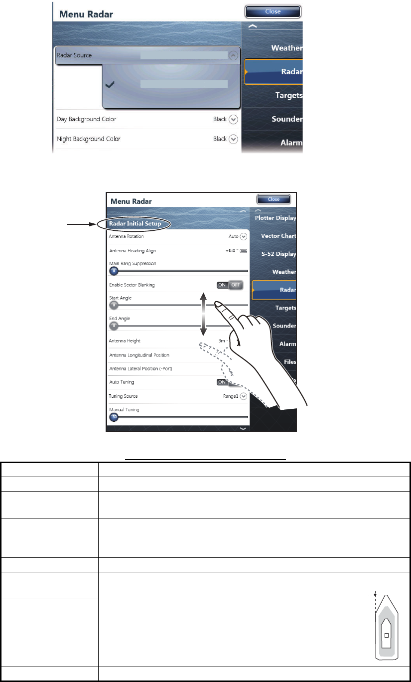
3. Tap [Radar Source], then select the appropriate antenna unit.
Note: If an antenna unit is connected but does not appear in the [Radar Source]
list, close the list and open it again. The name of the antenna unit should appear
with a check mark, as in the example below.
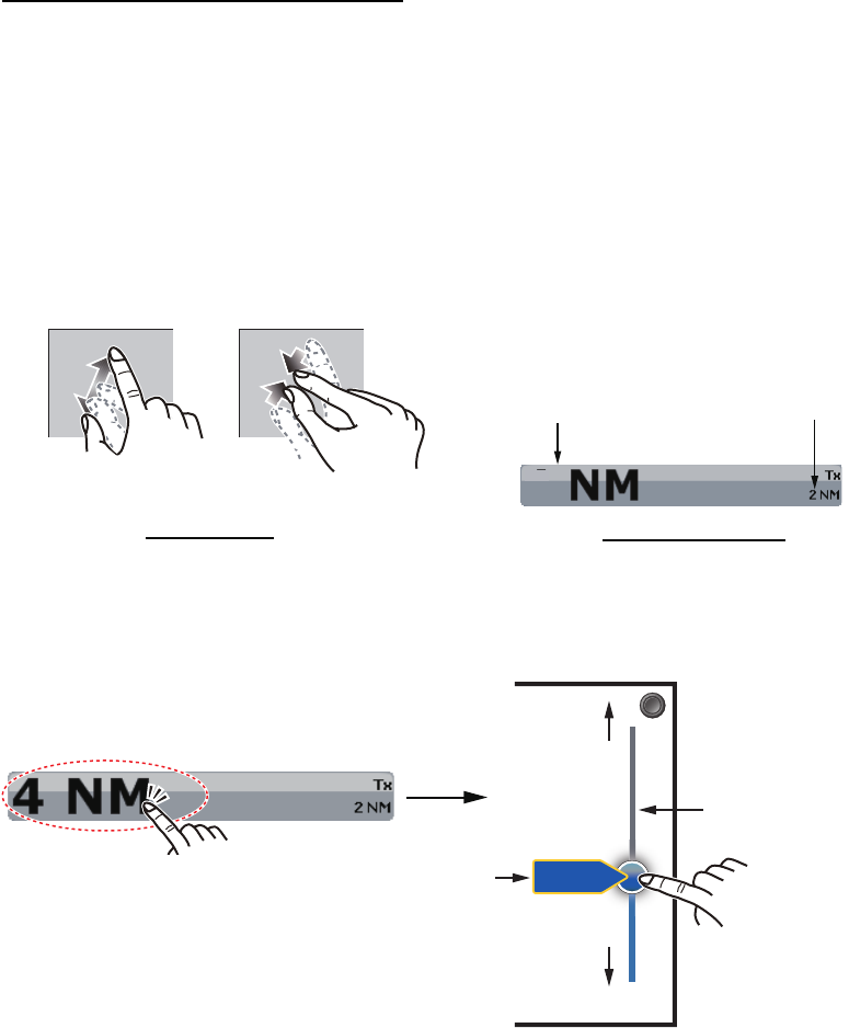
4. Drag the [Radar] menu display the menu item [Radar Initial Setup], then tap
[Radar Initial Setup].
5. Referring to the tables below, set up the radar.
[Radar] menu - [Radar Initial Setup]
[Radar] menu - [Antenna Position]
Menu item Description
[Antenna Rotation] Select the speed of antenna rotation.
[Antenna Heading Align] See "How to align the antenna heading" on page 10.
[Main Bang Suppression] If main bang appears at the screen center, slide the circle
icon so that the main bang disappears, while watching the
radar echo at the left-hand side of the display.
[Enable Sector Blanking] Up to two sectors may be selected for blanking (no trans-
mission). Select [ON] to enable this feature. Set the start
and end angles (0° to 359°).
[Enable Sector 2 Blanking]
Menu item Description
[Longitudinal (from bow)] Referring to the figure on the right, enter the
radar antenna positioning bow-stern (Longi-
tudinal) and port-starboard (Lateral) position
from the origin.
[Lateral (-Port)]
[Antenna Height] Select the height of the antenna above the waterline.
[Radar Monitoring] Display various information regarding the connected ra-
dar.
[ARPA Advanced Settings] Do not change these settings.
[Set Hardware To Factory
Default]
Resets the radar selected at [Radar Source] to factory
default.
[Reset Default Settings] Resets [Radar] menu settings to default.
xxxxxxxx-xxxxxxxxxx
OriginOrigin
2. WIRING
10
How to align the antenna heading
You have mounted the antenna unit facing straight ahead in the direction of the bow.
Therefore, a small but conspicuous target dead ahead visually should appear on the
heading line (zero degrees).
In practice, you will probably observe some small bearing error on the display because
of the difficulty in achieving accurate initial positioning of the antenna unit. The follow-
ing adjustment will compensate for the error.
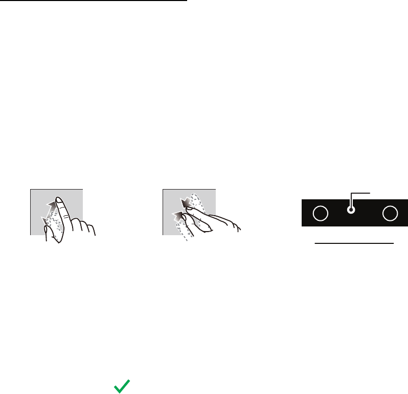
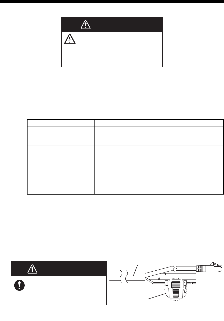
1. Set your radar with 0.125 and 0.25 NM range and the head up mode.
You can select a range by using the pinch action. The range appears at the bottom
right of the screen. Range may also be selected using the slide bar displayed on
the right-hand side of the radar display area. Drag the bar up to zoom in, or down
to zoom out.
2. Turn the vessel’s bow toward a target.
3. Tap the [Home] icon to show the home screen and display mode settings.
4. Tap [Radar] to show the [Radar] menu.
5. Drag the [Radar] menu to show the [RADAR INITAL SETUP] menu.
6. Tap [Antenna Heading Align].
7. Key in the offset value so that the target is displayed at the very top of the screen
(setting range: +179.9° to -180°, +: clockwise direction, -: counterclockwise direc-
tion), then tap the icon.
8. Confirm that the target echo is displayed at correct bearing on the screen.
2.3.2 Initial setup for NavNet TZtouch (TZT9/TZT14/TZTBB)
1. Press the Home key (or tap the Home icon).
2. Select [Menu] on the menu icon bar to open the main menu.
3. Select [Radar].
4. Select [Radar Source] on the [Menu Radar] sub menus, then select the radar type
connected.
Note: If a antenna unit is connected but does not appear in the [Radar Source]
list, close the list and open it again. The name of the antenna unit should appear
with a check mark, as in the example below.
Range
Increase rangeIncrease range Reduce rangeReduce range
Radar indications
HU NM Tx
3.650
2. WIRING
11
5. Drag the [Menu Radar] sub menus to find the menu item [Radar Initial Setup].
Menu Radar (Radar Initial Setup)
Menu item Description
[Antenna Rotation] Select the speed of antenna rotation.
[Antenna Heading
Align]
See the topic of "How to align the antenna heading" on page 2-12.
[Main Bang Sup-
pression]
If main bang appears at the screen center, slide the circle icon so
that the main bang disappears, while watching the radar echo at
the left-hand side of the display.
[Antenna Height] Select the height of the antenna above the waterline.
[Antenna Longitu-
dinal Position] Enter the antenna positioning bow-stern (Longitudi-
nal) and port-starboard (lateral) position from the ori-
gin.
[Antenna Lateral
Position (-Port)]
Others See Operator’ Manual for TZT9/14/BB.
xxxxxxxx
-
xxxxxxxxxx
xxxxxxxx-xxxxxxxxxx
Title
Origin
2. WIRING
12
How to align the antenna heading
You have mounted the antenna unit facing straight ahead in the direction of the
bow. Therefore, a small but conspicuous target dead ahead visually should ap-
pear on the heading line (zero degrees).
In practice, you will probably observe some small bearing error on the display be-
cause of the difficulty in achieving accurate initial positioning of the antenna unit.
The following adjustment will compensate for the error.
1) Select a range between 0.125 and 0.25 NM and set the mode to “head up“.
You can select a range by a pinch action. The range and range ring interval
appear at the bottom left of the screen.
For TZTBB, you can also control the range in the operation as follows. Tap
the radar scale box at the bottom left-hand corner of the screen to display the
slider bar. Drag the circle icon to set the range scale.
2) Turn the vessel’s bow toward a target.
3) Press the Home key (or tap the Home icon), then select [Menu] icon, [Radar],
and [Antenna Heading Align] in that order to show the numeric software key-
board.
4) Key in the offset value so that the target is at the very top of the screen (setting
range: +/- 0° to 180°, +: clockwise direction, -: counterclockwise direction),
then tap [Save].
5) Confirm that the target echo is displayed at correct bearing on the screen.
1
Range Range ring interval
Range indications
Zoom outZoom in
Pinch action
Tap the area circled in the dashed line to
display the slider bar.
Note: You can switch between transmit and
stand-by by tapping the right side of the
radar scale box.
Drag the circle
icon to set the
range scale.
Slider bar
Zoom in
Zoom out
4NM
Current
range
13
3. MAINTENANCE, TROUBLE-
SHOOTING
3.1 Maintenance
Regular maintenance is important for good performance. Check the points mentioned
below every 3 to 6 months to keep the radar sensor in good working order. Observe
the safety instructions at the front of this manual when working on the mast.
3.2 Replacement of Fuse
The 5A fuse (Type: FRU-2P5S-FU-5A-A, Code No.: 000-168-869-10) in the fuse hold-
er on the power/Network cable protects the radar sensor from overcurrent and equip-
ment fault. If you cannot turn on the power, check the fuse to see if it has blown. If the
fuse has blown, find the reason before you replace the fuse. If the fuse blows again
after the replacement, contact your dealer for advice.
Check point Action
Fixing bolts
• Corrosion
• If they are tightened
• Replace corroded bolts.
• Tighten loosened bolts.
• Coat new bolts with marine sealant.
Radome
• Cracks
• Foreign material
If a crack is found, repair it temporarily with a small
amount of sealing compound or adhesive. Bring the unit
to your dealer for permanent repairs.
Foreign material on the radome can cause a consider-
able drop in sensitivity. Remove foreign material with a
freshwater-moistened cloth. Do not use commercial
cleaners to clean the sensor; they can remove paint and
markings or deform the plastic.
WARNING
DO NOT OPEN THE SENSOR.
Electrical shock hazard
There are no user-serviceable parts
inside. Only qualified personnel are
allowed to work inside the equipment.
WARNING
WARNING
Use the proper fuse.
Use of a wrong fuse can cause
fire or damage the equipment.
Fuse holder
How to replace the fuse
Open the fuse holder cover and replace
the fuse. Then close the cover.
Power/LAN cable

3. MAINTENANCE, TROUBLE- SHOOTING
14
3.3 Troubleshooting
The table below provides simple troubleshooting procedures to restore normal opera-
tion. If you cannot restore normal operation, contact your dealer for advice.
Trouble Remedy
The radar type does not appear
on the multi function display de-
vice.
• Check if the power/Network cable is connected
to the power source and the power source is on.
• Check the power cable for damage.
• Check if the fuse has blown.
• Check the voltage of ship’s main.
• Check the software version of the multi function
display device.
The radar type appears on the
multi function display device, but
the radar display does not appear
or transmission does not start.
Check the software version of multi function display
device.
The radar appears on the multi
function display device, but disap-
pears when the transmission
started or continue rebooting.
Check the power voltage is sufficient.
Transmission starts, but echoes
do not appear or weak echoes oc-
cur
Check the settings of GAIN/SEA/RAIN.
Too many interferences • Turn the interference rejector on.
• Turn on/off the transmission.
• Change the transmission channel.
Marks and characters appear on
the display, but echoes do not ap-
pear.
Check that the power/Network cable is fastened.
You changed the range, but the
radar picture does not change.
• Try to zoom in or out the radar display.
• Turn the power off and on.
Signal strength is too low. Have a technician check the radar.
15
4. PROCEDURE FOR RETROFIT
4.1 Required Tools and a Part for Retrofit
Below tools are required for retrofit. A rubber gasket is required for retrofit.
• Positive and negative screwdrivers
• Rubber gasket (two holes) provided as an optional kit
• A fuse with below characteristics is required for retrofit. Local supply.
Current rating: 5A, Voltage rating: 32V, Cable Diameter 12AWG (2.053 mm)
• Refer to the below table about the limitation of cable length according to the ship’s
main supply.
4.2 Retrofit Procedures
Note 1: Retrofit from DRS2D, DRS4D and DRS6A is available with below procedures.
Note 2: Below procedures are for using a 5A fuse.
Note 3: Make sure that the multi function display device is turned off and the two-way
cable MOD-ASW0001 is unplugged from the multi function display device and the
power supply unit before starting below procedures.
Procedures for the radome
1. Put the radome upside down.
2. Unfasten six retaining screws at the bottom of radome and open it.
Ship’s Main Supply Limitation on Cable Length
10.8 VDC Unavailable
12 VDC Less than 10 m only
24 VDC No limitation
4. PROCEDURE FOR RETROFIT
16
3. Press down the button of WAGO of power terminal from the top small window with
using the negative screwdriver and pull out the power cable.
4. Unfasten two screws of cable clamps of power cable and Network cable.
5. Detach the cable clamps from power cable and Network cable and keep a Network
cable clamp for later use.
6. Unplug the Network cable from the port. Note that the Network cable port is upside
down.
Wire
Press down
Pull out
LAN cableLAN cableLAN cable
Power cablePower cablePower cable
Unfasten cable clamp
and detach from cable
Unfasten cable clamp
and detach from cable
Unfasten cable clamp
and detach from cable
Unfasten cable clamp
and detach from cable
Unfasten cable clamp
and detach from cable
Unfasten cable clamp
and detach from cable
4. PROCEDURE FOR RETROFIT
17
7. Unfasten three screws at the bottom of the mounting base to remove the fixing
plate for the gasket and keep screws and fixing plate for later use.
8. Remove the pre-attached cable and a pre-attached gasket.
9. Insert the existing power cable and Network cable to the radome from the bottom
of radome.
10. Attach the clamps to the existing power cable and Network cable with the cable
clamps detached in step 4.
11. Push these two cables into the slits of the provided gasket. The sizes of holes on
a gasket differ according to the diameter of cables.
Note: The ends of the gasket are different. Larger end should be up.
Use this location for keeping screws.
Fixing plate for gasket
Up
Small
Large
φ6.9
φ6
4. PROCEDURE FOR RETROFIT
18
12. Connect the power cable to the power terminal.
13. Plug the Network connector to the port.
Insert the shield cable
(power) with this clamp.
Insert the cable (LAN)
with this locking saddle.
LAN port
Plug in positive side (+) to the
left hole and negative side (-)
to the right hole.
Power terminal
Wire
Press down
Insert
From left,
White (DC+) cable
Black (DC-) cable
No connection (FG)
4. PROCEDURE FOR RETROFIT
19
14. Slide the gasket on cables so that the amount of cable above the gasket is lower
than the RF chassis.
Note 1: If the two-way cable touches the platform near the mounting base, wind
vinyl tape around the cable at the point where it is bent.
Note 2: The gasket has a protruding point and a radome chasis has a dent where
these points matches as below illustration.
15. Fasten the clamps of power cable and Network cable.
16. Screw down the clamps to the location according to the above illustration.
17. Confirm that the rubber gasket is properly positioned and that the triangle mark on
the cover is aligned with the triangle mark on the mounting base, then fasten the
fixing screws for the cover.
Cable
This height should be
lower than the RF unit
when installed to the
bottom of the sensor.
Gasket
Triangle marks
Cover
Mounting base
4. PROCEDURE FOR RETROFIT
20
There two ways to attach the fuse box to the existing cable MOD-ASW0001 as below.
Procedures for Attaching the Fuse Box to Existing Cables 1
1. Detach the power cable from PSU-012 or PSU-017.
2. Cut the power cable of two-way cable MOD-ASW0001 so that the cable can be
connected to a fuse box (local supply) and ship’s main supply.
3. Connect the white cable to the fuse box and solder the both sides of power cable
to it.
4. Connect the white cable to the positive side of power supply.
5. Connect the black cable to the negative side of power supply.
6. Connect the Network cable to the multi function display device.
Procedures for Attaching the Fuse Box to Existing Cables 2
1. Detach the power cable from PSU-012 or PSU-017.
2. Cut the power cable of existing two-way cable MOD-ASW0001 so that the cable
can be connected to the selectable power/Network cable (CP03-36400, CP03-
36410, CP03-36420 or CP03-36430) and ship’s main supply.
3. Cut the power cable of the selectable power/Network cable (CP03-36400, CP03-
36410, CP03-36420 or CP03-36430) so that the fuse box of it can be used.
4. Connect the white cable of MOD-ASW0001 to the power cable of the selectable
power/Network cable with a fuse box and solder the both sides of power cable to it.
5. Connect the white cable to the positive side of power supply.
6. Connect the black cable to the negative side of power supply.
7. Connect the Network cable to the multi function display device.
-
+
White (DC +) cable
Black (DC -) cable
Ground
DRS4D-NXT
SP - 1
E3649S01A
150623
SPECIFICATIONS OF RADAR SENSOR
DRS4D-NXT
1 RADIATOR
1.1 Antenna type Patch array antenna
1.2 Antenna length 2 ft
1.3 Horizontal beam width 4.0° typical (-3dB), Enhanced 1/2/3: 3.2°/2.8°/2.4°
1.4 Vertical beam width 20° (-3dB)
1.5 Sidelobe attenuation -24 dB
1.6 Rotation 24/36/48 rpm coupled with range or 24 rpm fixed (select)
2 RADAR FUNCTION
2.1 Tx frequency
Ch # P0N (MHz) Q0N (MHz)
1 9380 9400
2 9400 9420
3 9420 9440
2.2 Output power 20 W nominal (equivalent to 4kW magnetron radar)
2.3 Intermediate frequency 83.75/103.75 MHz
2.4 Range, Pulse length and Pulse Repetition Rate (PRR)
Range (NM) Pulse length ( s)
(non-modulated/modulated)
PRR
(Hz approx.)
0.0625 to 0.5 0.08/5.0 2000
0.75 to 1 0.15/7.5 2000
1.5 to 2 0.3/11 2000
3 to 4 0.6/13 2000
6 to 12 1.2/15 2000
16 to 36 1.2/18 1400
2.5 Minimum range 25 m
2.6 Range resolution 20 m
2.7 Bearing accuracy ±1°
2.8 Warm-up time Null
3 INTERFACE
3.1 Number of port LAN: 1 port, Ethernet, 100Base-TX, RJ45
3.2 Data sentences IEC61162-1/2
Input GGA, GLL, GNS, HDG, HDM, HDT, RMA, RMC, THS, VHW, VTG
4 POWER SUPPLY
12-24 VDC: 2.5-1.3 A
5 ENVIRONMENTAL CONDITIONS
5.1 Ambient temperature -25°C to +55°C (storage: -30°C to +70°C)
5.2 Relative humidity 93% or less at +40°C
5.3 Degree of protection IP26
5.4 Vibration IEC 60945 Ed.4
6 UNIT COLOR
N9.5 (cover), PANTONE2945C (bottom)
Page for Packing List
(Not ready on July 23.)

The paper used in this manual
is elemental chlorine free.
・FURUNO Authorized Distributor/Dealer
9-52 Ashihara-cho,
Nishinomiya, 662-8580, JAPAN
A
:
0000
Printed in Japan
All rights reserved.
Z
:
JUL
.
02, 2015
Pub. No.
IME-36490-Z
(
TASU
)
DRS4D-NXT
0 0 0 1 9 1 0 8 2 1 0