Furuno USA 9ZWRTR120 Transceiver for Radar User Manual OME 36660 A
Furuno USA Inc Transceiver for Radar OME 36660 A
UserManual.wiki
>
Furuno USA
>
9ZWRTR120 User Manual
User Manual
Navigation menu
Upload a User Manual
Namespaces
Wiki Guide
HTML
PDF
Info
Views
User Manual
Discussion / Help
Navigation
![ii SAFETY INSTRUCTIONSWARNINGIndicates a condition that can cause death or serious injury if not avoided.CAUTIONIndicates a condition that can cause minor or moderate injury if not avoided. Warning, Caution Mandatory ActionProhibitive ActionRead these safety instructions before you operate or install the equipment. WARNINGRadio Frequency Radiation HazardThe radar antenna sends the electromagnetic radio frequency (RF) energy. This energy can be dangerous to you, especially your eyes. Do not look at the radiator or near the antenna when the antenna is rotating.The distances at which RF radiation levels of 100 W/m2, 50 W/m2 and 10 W/m2 exist are shown in the table.Note: If the antenna unit is installed at a close distance in front of the wheel house, prevent the transmission in that area to protect passengers and crew from microwave radiation. Set the [Sector Blanks] in the [System] menu.Distance to100 W/m2 pointDistance to50 W/m2 pointDistance to10 W/m2 pointWorst case 1.1 mStandard SteeringDisplay unit 0.45 m 0.30 mCAUTIONCAUTIONM1815 Antenna unit 1.70 m 1.05 mUnitObserve the following compass safe distances to prevent deviation of a magnetic compass.WARNINGDo not open the equipment.The equipment uses high voltage that can cause electrical shock. Refer any repair work to a qualified technician.Before turning on the radar, be sure no one is near the antenna.Prevent the potential risk of being struck by the rotating antenna, which can result in serious injury or death.If water leaks into the equipment or something is dropped into the equipment, immediately turn off the power at the switchboard.Fire or electrical shock can result.If the equipment is giving off smoke or fire, immediately turn off the power at the switchboard.Fire or electrical shock can result.Do not disassemble or modify the equipment.Fire, electrical shock or serious injury can result.Do not place operate the equipment with wet hands.Electrical shock can result.](https://usermanual.wiki/Furuno-USA/9ZWRTR120/User-Guide-3299114-Page-3.png)

![FOREWORDxRadar function availabilityThe Model 1815 is available in two types, [River] (river use) and [Sea] (sea use). Some functions may not available depending on the type selected See the table below for item and availability.Type and function availabilityNote on Chinese font: The Chinese font used in this equipment is Ricoh Company Ltd.'s Ricoh bitmap font.Item Type Page referenceRiver SeaAutomatic menu clo-sureMenu closes automatically.Effective radius dot count240 dotsEcho color Select the echo display colorEcho color customiz-ingCan customize the echo display color.Echo area Select the display area from [Normal] or [Full Screen].Base text display Can show or hide the base text indications.Range preset Select the radar rang-es to use.Unit defaults1) range 2) speed1) KM 2) km/h, m/s 1) NM 2) knBearing scale Graduation every 1°, 5°, 10°, 30°, no numeric in-dication, displayed in the effective radiusVRM unit Can set the VRM unit independently from the range unit.Range unit Can change the range unit when transmitting.AIS symbol color Select the AIS symbol color from [Green], [Red], [Blue], [White] or [Black].Vector reference Select the display mode for the vector from [Rel-ative] or [True].TT number Empty numbers numbered in ascending orderHeading line erasure Heading line, EBL, VRM, guard zone, etc. tem-porarily erased.](https://usermanual.wiki/Furuno-USA/9ZWRTR120/User-Guide-3299114-Page-11.png)


![3-13. INITIAL SETTINGS3.1 How to Select LanguageDo the following to select the language to use.1. Press the ( ) key on the display unit to turn on the power.2. Press the MENU/ESC key to show the menu.3. Press , on the Cursorpad to select [Factory], then press the ENTER key.The cursor moves to the menu item section and [Language] is selected. Press the EN-TER key again to show the language options.4. Press , on the Cursorpad to select a language, then press the ENTER key.5. Press the MENU/ESC key to close the menu.㻌㻌㼀㼄](https://usermanual.wiki/Furuno-USA/9ZWRTR120/User-Guide-3299114-Page-24.png)
![3. INITIAL SETTINGS3-23.2 How to Select Radar Purpose1. Press the MENU/ESC key to show the menu.2. Press , on the Cursorpad to select [Factory], then press the ENTER key.3. Press , on the Cursorpad to select [Usage], then press the ENTER key.4. Press , on the Cursorpad to select a [River] or [Sea], then press the ENTER key.5. Press the MENU/ESC key to close the menu.3.3 Initial Settings1. Press the MENU/ESC key to show the menu.2. Press , on the Cursorpad to select [Installation], then press the ENTER key.3. While holding down and pressing the ENTER key, press the ALARM key five times to unlock the [Installation] menu.4. Press , on the Cursorpad to select the item to set, then press the ENTER key.5. Press , on the Cursorpad to select the option required, then press the ENTER key6. After setting all items, press the MENU/ESC key to close the menu.](https://usermanual.wiki/Furuno-USA/9ZWRTR120/User-Guide-3299114-Page-25.png)
![3. INITIAL SETTINGS3-3Item description• [Simulation]: Normally, set to [Off.] To view the demonstration picture, select [On].• [Antenna Rotation]: Select [Rotate] to rotate the antenna and transmit radar puls-es. The [Stop] setting, which transmits radar pulses without rotating the antenna, is for use by the service technician.• [Heading Alignment]: You have installed the antenna unit so that the unit faces to-ward the bow. A target at the front of the boat and aligned with the bow must appear on the heading line (zero degrees). If the target does not appear on the heading line, do the procedure shown below to adjust the heading.1. Set ship heading toward an acceptable target (for example, ship at anchor or buoy) at a range between 0.125 and 0.25 nautical mile.2. Transmit the radar at the range of 0.25 nautical mile and measure the bearing of that target relative to ship heading with an EBL.3. Open the [Installation] menu and select [Heading Adjust].4. Press the ENTER key to show the heading adjustment window.5. Press or to set the value measured at the above step 2. Check that the target appears on the heading line.6. Press the ENTER key to finish.• [Sweep Timing]: This adjustment gives correct radar performance on short ranges. The radar measures the time required for a transmitted echo to go to the target and return to the source. The received echo appears on the display according to the measured time. The sweep must start from the center of the display.A trigger pulse created in the display unit goes to the antenna unit through the signal cable to acti-vate the transmitter (magnetron). The time taken by the signal to move to the anten-na unit changes, according to the length of the signal cable. During this period, the display unit must wait before the radar starts the sweep. When the display unit is not adjusted correctly, the echoes from a straight object will not appear as a straight line. The target appears "pushed" or "pulled" near the picture center. The range to objects are shown at wrong distances.1. Transmit on the shortest range, then adjust the gain and the A/C SEA.2. Visibly select a target that creates a straight line (harbor wall, straight piers).3. Open the [Installation] menu and select [Timing Adjust].4. Press the ENTER key to show the timing adjustment window.5. Press or to make straight the target selected at step 2, then press the EN-TER key to finish.(1) Target pulled (2) Correct (3) Target pushed outward](https://usermanual.wiki/Furuno-USA/9ZWRTR120/User-Guide-3299114-Page-26.png)
![3. INITIAL SETTINGS3-4• [Main Bang Suppression]: Reduce the main bang (black hole at center of screen), which appears at the display center on short ranges, as follows.1. Transmit on the shortest range.2. Open the [Installation] menu and select [MBS Adjust].3. Press the ENTER key to show the MBS adjustment window.4. Press or on the Cursorpad so that the main bang is reduced.5. Press the ENTER key to finish.• How to automatically set the equipment: The tuning, timing, and video can be au-tomatically adjusted as follows.Note: Before doing this procedure, transmit the radar more than 10 minutes on a long range and check that [Sector Blank] is [Off].1. Transmit on the maximum range.2. Open the [Installation] menu and select [Auto Initial Setup], then press the EN-TER key.3. Press on the Cursorpad to select [Yes], then press the ENTER key.The tuning adjustment begins automatically, and the message "Tuning adjusting" appears during tuning adjustment. After the tuning adjustment is completed, the tim-ing and video are adjusted in that order. The messages "Timing adjusting" and "Vid-eo adjusting" appear during those adjustments. After all adjustments are completed, the window disappears. If the result for any item is not best for your con-ditions, manually adjust the item according to the procedure in this section.• [Total On Time]: You can set the total on time as shown below.1. Open the [Installation] menu and select [Total On Time]. 2. Press the ENTER key.3. Press or on the Cursorpad to set value. The range is 000000.H to 999999.9 H.4. Press the ENTER key to finish.• [Total TX Time]: You can set the total TX time as shown below.1. Open the [Installation] menu and select [Total TX Time]. 2. Press the ENTER key.3. Press or on the Cursorpad to set value. The range is 000000.H to 999999.9 H.4. Press the ENTER key to finish.• [Memory Clear]: The memory clear feature restores all settings to default, including the default settings for the antenna connected to LAN.1. Open the [Installation] menu and select [Memory Clear]. 2. Press the ENTER key.3. Press or on the Cursorpad to select [Yes], then press the ENTER key.4. Press the ENTER key to finish.](https://usermanual.wiki/Furuno-USA/9ZWRTR120/User-Guide-3299114-Page-27.png)
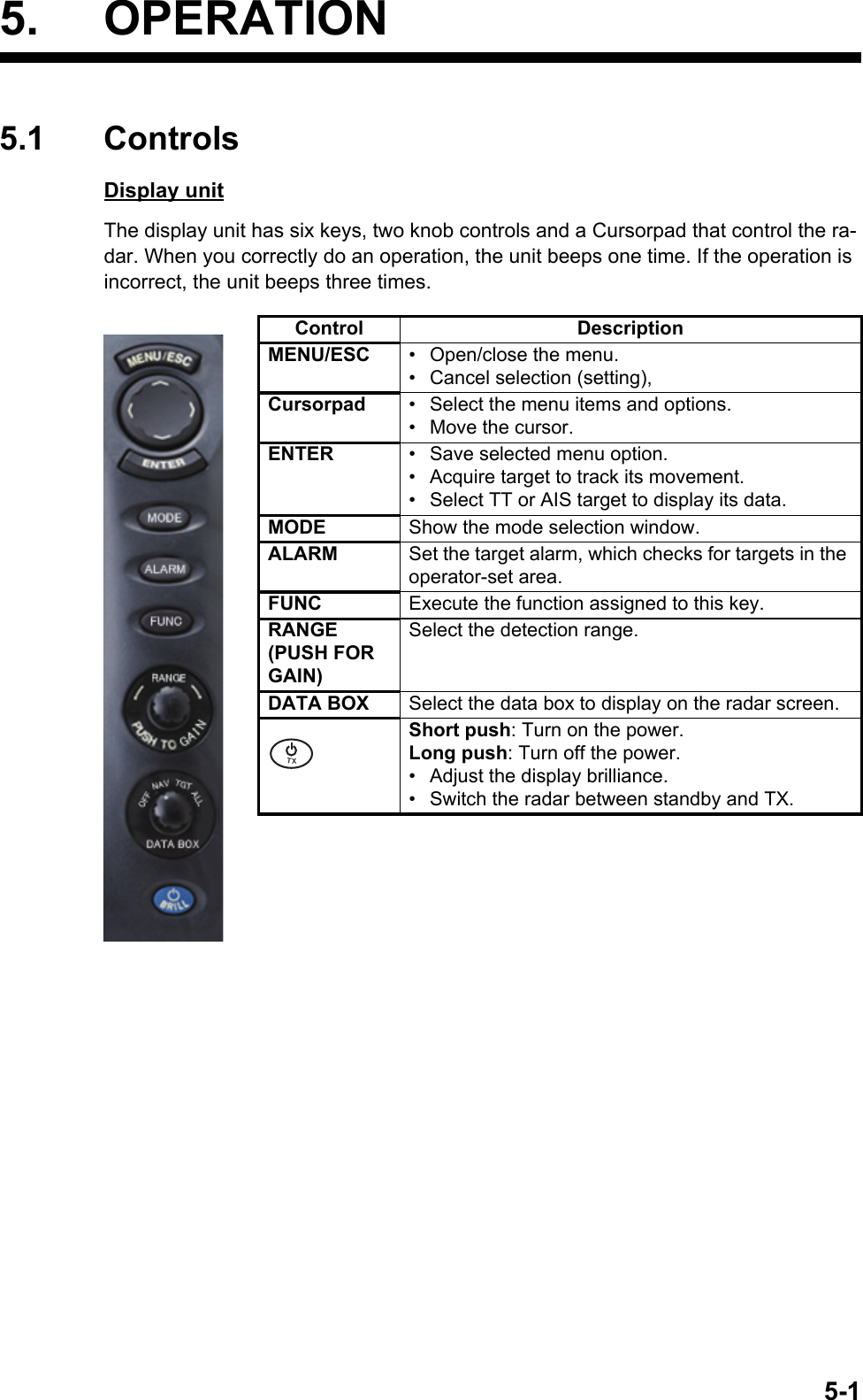
![5. OPERATION5-25.2 How to Turn the Radar On/Off and TransmitPress the key to turn on the radar. To turn off the radar, press and hold down the key until the screen turns off.Start-up screenWhen you turn on the power, the initialization screen appears followed by the start-up screen. The start-up screen shows the model name, program number and the results of the ROM and RAM check, OK or NG (No Good). If the test results are normal, the stand-by screen ([Normal] or [Nav]) appears approx. 5 sec. later, and the time remain-ing for magnetron warm-up (approx. 90 seconds) is counted down on the screen. If NG appears, contact your dealer for instruction.After the magnetron has warmed, the indication [ST-BY] at the screen center. The ra-dar is now ready to transmit radar pulses.Push the key to show the [Brill/Panel] window. The cursor is selecting [TX/STBY]. Press the ENTER key to transmit the radar pulses. The key switches between standby and transmit. The antenna rotates in trans-mit and is stopped in standby. Because the magnetron ages with use, set the radar in stand-by when you are not using the radar, to extend the life of the magnetron.㻌㻌㼀㼄㻌㻌㼀㼄㻌㻌㼀㼄](https://usermanual.wiki/Furuno-USA/9ZWRTR120/User-Guide-3299114-Page-31.png)
![5. OPERATION5-35.3 Display IndicationsDisplay indicationsHeadingNav data: Appears at screen bottom when [Data Box]in the [Display] menu is set to [Nav] or [All]. Appropriatesensors required to display nav data.Cursor data(Range and bearing or L/L position)Display modeRange ring intervalRangeTrail referenceNo. 1 EBL bearingNo. 2 EBL bearingOffcenter(M: Manual, A: Auto, C: Custom)North markerTuning indicatorTarget Alarm 1 (2)indicationsNo. 1 VRM rangeNo. 2 VRM rangeWATCHMANTarget alarm zone 1Target alarm zone 2350.0°TRAIL(T)15 S +1.51.5NMNM WTCHeading lineRange ringNo. 2 VRMNo. 2 EBLZoom windowZoom cursorNo. 1 EBLNo. 1 VRMCursorBearing scaleHDG0.5H UP TUNEAUTOALM1_INALM2_INIR 1VRM0.889NM0.422NMInterference rejector22.0°R270.0°RES 1EAV 1EBLEcho stretchEcho averaging241.0°R 1.592NMVECT TRUE 05:00Vector timeZOOM(R) Zoom indication+Trail timeLAT 34°56.123NLON 135°34.567ESPEED 12.3KNLAT 34°56.123NLON 135°34.567ETTG 01:00B RG 14.8°RNG 0.876NMTT G 00:20OWN SHIP + CURSOR WAYPOINTOFFCENT(A)](https://usermanual.wiki/Furuno-USA/9ZWRTR120/User-Guide-3299114-Page-32.png)
![5. OPERATION5-45.4 How to Adjust Display Brilliance, Panel DimmerYou can adjust the display brilliance and panel dimmer as follows:1. Press the key to show the [Brill/Panel] window.Brill/Panel dialog box2. Press the ENTER key (or , ) to select [Brill] or [Panel] as required.3. Use the Cursorpad ( or ) to adjust. (For brilliance, you can also use the key.)4. Press the MENU/ESC key to close the window.5.5 Menu DescriptionThis MODEL 1815 series has 14 menus and 7 sub menus. Below is the basic proce-dure for menu operation.1. Press the MENU/ESC key to open the menu.Menu㻌㻌㼀㼄㻌㻌㼀㼄CursorMenu itemsand currentsettingsCurrently selected menuScroll bar (Indicates menus currently not shown in menuwindow. Black vertical line indicates location in menu.You can see the menus and sub menus currently not shownby using or .)MenuTitle barGuide message(The simple explanation for the current menu.)](https://usermanual.wiki/Furuno-USA/9ZWRTR120/User-Guide-3299114-Page-33.png)
![5. OPERATION5-52. Use the Cursorpad ( or ) to select a menu or a sub menu. The cursor (yellow) in the Menu column indicates the menu currently selected. The menu items in the right window change according to the menu selected.Menu description[Brill/Color]: Adjust the brilliance and color.[Display]: Set up the display-related features.[Echo]: Adjust the echo features.[Alert Settings]: Customize the user settings.[Alarm]: Set up the alarm items.[Trails]: Process trails of the radar targets.[Tuning]: Adjust the radar tuning.[Others]: Set up other items.[Target]: Set up the targets configuration.[OS/Barge Mark]: Set up the own ship mark and barge mark.[TT]: Set up tracked targets.[AIS]: Set up AIS targets.[GPS]: Set up GP-320B (Black-Box GPS).[System] [Initial]: Initial settings. [Tests]: System diagnostic and LCD test. [Sector Blanks]: Set up the sector blanks to prevent the transmission in a certain area. [Units]: Set up units.[TT]: Set up TT system. [Installation] and [Factory]: For use by the installer. See the Installation Man-ual.3. Press the ENTER key to switch the control to the menu items column. The cursor in the menu column now turns gray and the cursor in the menu items column is yellow.To switch the control from the menu items column to the menu column, use the MENU/ESC key. The color of the title bar of the active column is blue and of the inactive column is gray.4. Use the Cursorpad ( or ) to select a menu item and press the ENTER key. A window with options for the related menu item appears.Example windows5. Use the Cursorpad ( or ) to select an option or numeric value.6. Press the ENTER key to save your selection. To close the window without saving, press he MENU/ESC key (instead of the ENTER key).7. Press the MENU/ESC key to close the menu.Display Color options Echo Brill setting window](https://usermanual.wiki/Furuno-USA/9ZWRTR120/User-Guide-3299114-Page-34.png)
![5. OPERATION5-65.6 TuningIn default, the radar receiver can be tuned automatically after turning the radar to TX. If you require fine tuning in manual, do the following:1. Transmit the radar and select the maximum range with the RANGE knob.2. Press the MENU/ESC key to open the menu.3. Use the Cursorpad ( or ) to select [Tuning] and press the ENTER key.Tuning menu4. Use the Cursorpad ( or ) to select [Tuning Mode] and press the ENTER key.Tuning Mode options5. Use the Cursorpad ( or ) to select [Manual] and press the ENTER key.6. Use the Cursorpad ( or ) to select [Manual Tuning] and press the ENTER key to show the manual tuning setting window.Manual Tuning setting window7. Use the Cursorpad ( or ) to adjust the tuning while you look at the tuning bar at the upper-right corner of the dis-play. The best tuning point is where the tuning bar moves to maximum value. The vertical bar on the tuning bar shows the tuning voltage.8. Press the ENTER key.9. Press the MENU/ESC key to close the menu.Note: If the automatic tuning does not give the correct tuning, run the [Tuning Initial-ization] again.TUNE MAN Tuning method (Manual)Tuning barVertical bar](https://usermanual.wiki/Furuno-USA/9ZWRTR120/User-Guide-3299114-Page-35.png)
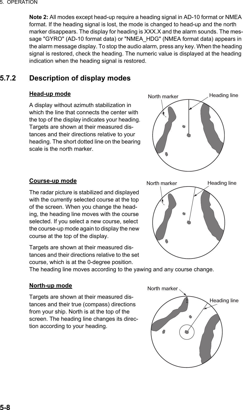
![5. OPERATION5-75.7 Display ModesThis radar has the display modes shown below. All modes except head-up require a heading signal. The true motion mode additionally requires position data.Relative Motion (RM)• [Head Up] (H UP)• [Course Up] (C UP)• [North Up] (N UP)• [True View]True Motion (TM)• [True Motion] (TM)5.7.1 How to select the display mode1. Press the MENU/ESC key to open the menu.2. Use the Cursorpad ( or ) to select [Display] and press the ENTER key.Display menu3. Use the Cursorpad ( or ) to select [Display Mode] and press the ENTER key.Display Mode options4. Use the Cursorpad ( or ) to select a display mode and press the ENTER key.5. Press the MENU/ESC key to close the menu.Note 1: The display mode is automatically switch to head up if the heading signal be-comes lost.](https://usermanual.wiki/Furuno-USA/9ZWRTR120/User-Guide-3299114-Page-36.png)