Furuno FR 8045 User Manual To The Cd7f2148 59b7 41b1 A966 B52f9aaf5a30
User Manual: Furuno FR-8045 to the manual
Open the PDF directly: View PDF ![]() .
.
Page Count: 120 [warning: Documents this large are best viewed by clicking the View PDF Link!]
- IMPORTANT NOTICES
- SAFETY INSTRUCTIONS
- TABLE OF CONTENTS
- FOREWORD
- SYSTEM CONFIGURATION
- 1. OPERATION
- 1.1 Controls
- 1.2 How to Turn the Radar On/Off and Transmit
- 1.3 Display Indications
- 1.4 How to Adjust Display Brilliance, Panel Dimmer
- 1.5 Menu Description
- 1.6 Tuning
- 1.7 Display Modes
- 1.8 How to Select a Range Scale
- 1.9 How to Adjust the Gain (sensitivity)
- 1.10 How to Reduce the Sea Clutter
- 1.11 How to Reduce the Rain Clutter
- 1.12 Automatic Adjustments of Sea and Rain Clutters
- 1.13 Cursor
- 1.14 Interference Rejector
- 1.15 How to Measure the Range to a Target
- 1.16 How to Measure the Bearing to a Target
- 1.17 How to Measure the Range and Bearing Between Two Targets
- 1.18 How to Select a Pulselength
- 1.19 Target Alarm
- 1.20 How to Off-center the Display
- 1.21 Zoom
- 1.22 Echo Stretch
- 1.23 Echo Average
- 1.24 Target Trails
- 1.25 How to Send the Target Position and Enter the Origin Mark
- 1.26 How to Hide the Heading Line Temporarily
- 1.27 Presentation Brilliance
- 1.28 Custom Setup
- 1.29 How to Program Function Keys (F1, F2 and F3 keys)
- 1.30 Noise Rejector
- 1.31 Wiper
- 1.32 How to Reduce Second-trace Echoes
- 1.33 Watchman
- 1.34 Color Selections
- 1.35 Navigation Data
- 1.36 Dynamic Range
- 1.37 Characteristics Curve
- 1.38 Waypoint Marker
- 1.39 Alarm Message
- 1.40 Echo Area
- 1.41 Initial Sub Menu
- 1.42 Units Sub Menu
- 1.43 Sector Blank
- 1.44 Other Menu Items
- 1.45 Remote Display
- 2. DESCRIPTION OF RADAR
- 3. ARPA OPERATION
- 3.1 Precautions for Use
- 3.2 Controls for Use with ARPA
- 3.3 ARPA Display On/Off
- 3.4 How to Acquire and Track the Targets
- 3.5 How to Stop the Tracking of ARPA Target
- 3.6 Vector Attributes
- 3.7 History Display (target past position)
- 3.8 ARPA Target Data
- 3.9 CPA/TCPA Alarm
- 3.10 Proximity Alarm
- 3.11 Lost Target
- 3.12 Symbol Color
- 4. AIS OPERATION
- 4.1 Controls for Use with AIS
- 4.2 AIS Display On/Off
- 4.3 AIS Symbols
- 4.4 Activating, Sleeping Targets
- 4.5 AIS Target Data
- 4.6 How to Sort Targets
- 4.7 Display Range
- 4.8 How to Display the Targets within a Specific Sector
- 4.9 Number of Targets to Display
- 4.10 Vector Attributes
- 4.11 History Display (target past position)
- 4.12 CPA/TCPA Alarm
- 4.13 Proximity Alarm
- 4.14 Lost Target
- 4.15 Symbol Color
- 4.16 How to Ignore Slow Targets
- 5. GPS OPERATION
- 6. MAINTENANCE, TROUBLESHOOTING
- APPENDIX 1 MENU TREE
- APPENDIX 2 GEODETIC CHART LIST
- SPECIFICATIONS
- INDEX
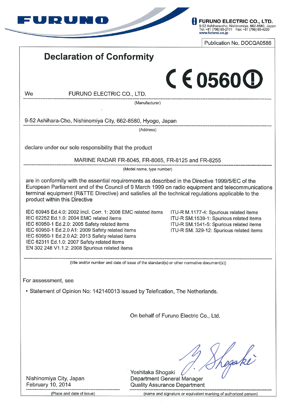
- DECLARATION OF CONFORMITY

OPERATOR'S MANUAL
www.furuno.com
Model
FR-8065
FR-8045
FR-8125
FR-8255
PRODUCT NAME: MARINE RADAR
MULTI-COLOR LCD RADAR

The paper used in this manual
is elemental chlorine free.
・FURUNO Authorized Distributor/Dealer
9-52 Ashihara-cho,
Nishinomiya, 662-8580, JAPAN
A
:
JAN
2014
.
Printed in Japan
All rights reserved.
A5
:
AUG
.
22, 2014
Pub. No.
OME-36320-A5
(
AKMU
)
FR-8045/8065/8125
0 0 0 1 7 8 5 0 2 1 0

i
IMPORTANT NOTICES
General
How to discard this product
Discard this product according to local regulations for the disposal of industrial waste. For disposal
in the USA, see the homepage of the Electronics Industries Alliance (http://www.eiae.org/) for the
correct method of disposal.
How to discard a used battery
Some FURUNO products have a battery(ies). To see if your product has a battery, see the chapter
on Maintenance. Follow the instructions below if a battery is used. Tape the + and - terminals of
battery before disposal to prevent fire, heat generation caused by short circuit.
In the European Union
The crossed-out trash can symbol indicates that all types of batteries
must not be discarded in standard trash, or at a trash site. Take the
used batteries to a battery collection site according to your national
legislation and the Batteries Directive 2006/66/EU.
In the USA
The Mobius loop symbol (three chasing arrows) indicates that Ni-Cd
and lead-acid rechargeable batteries must be recycled. Take the used
batteries to a battery collection site according to local laws.
In the other countries
There are no international standards for the battery recycle symbol. The number of symbols can
increase when the other countries make their own recycle symbols in the future.
• This manual has been authored with simplified grammar, to meet the needs of international users.
• The operator of this equipment must read and follow the descriptions in this manual. Wrong oper-
ation or maintenance can cancel the warranty or cause injury.
• Do not copy any part of this manual without written permission from FURUNO.
• If this manual is lost or worn, contact your dealer about replacement.
• The contents of this manual and equipment specifications can change without notice.
• The example screens (or illustrations) shown in this manual can be different from the screens you
see on your display. The screens you see depend on your system configuration and equipment
settings.
• Save this manual for future reference.
• Any modification of the equipment (including software) by persons not authorized by FURUNO will
cancel the warranty.
• All brand and product names are trademarks, registered trademarks or service marks of their re-
spective holders.
• Ricoh bitmap font is a trademark or registered trademark of Ricoh Company, Ltd.
Cd
Ni-Cd Pb
ii
SAFETY INSTRUCTIONS
WARNING
Radio Frequency Radiation Hazard
WARNING
Indicates a condition that can cause death or serious
injury if not avoided.
CAUTION
Indicates a condition that can cause minor or moderate
injury if not avoided.
Warning, Caution Mandatory Action
Prohibitive Action
Read these safety instructions before you operate the equipment.
The radar antenna sends the electromagnetic radio frequency (RF) energy. This energy
can be dangerous to you, especially your eyes. Do not look at the radiator or near the
antenna when the antenna is rotating.
The distances at which RF radiation levels of 100 W/m
2
and 10 W/m
2
exist are shown in
the table.
Note: If the antenna unit is installed at a close distance in front of the wheel house,
prevent the transmission in that area to protect passengers and crew from microwave
radiation. Set the [Sector Blanks] in the [System] menu.
FR-8065
100W/m210W/m2
FR-8125
FR-8255
FR-8045
Model
XN-12A
XN-13A
XN-12A
XN-13A
XN-12A
XN-13A
XN-12A
XN-13A N/A
N/A
N/A
N/A
N/A
N/A
1.1m
1.0m
1.9m
0.6m
0.4m 3.1m
4.6m
1.7m
2.1m
1.9m
SAFETY INSTRUCTIONS
iii
WARNING
ELECTRICAL SHOCK HAZARD
Do not open the equipment.
Only qualified persons can work
inside the equipment.
Turn off the power before you
service the antenna unit. Post a
warning sign near the power
switch not to turn on the power
while you service the antenna
unit.
Prevent the potential risk of being
struck by the rotating antenna and
exposure to RF radiation hazard.
Do not disassemble or modify
the equipment.
Fire or electrical shock can occur.
Turn off the power immediately
if water leaks into the equipment
or smoke or fire is coming
from the equipment.
Failure to turn off the equipment
can cause fire or electrical shock.
Use the correct fuse.
A wrong fuse can damage the
equipment and cause fire.
Keep heater away from the
equipment.
Heat can change the equipment
shape and melt the power cord, which
can cause fire or electrical shock.
Do not put liquid-filled containers
on the top of the equipment.
Fire or electrical shock can occur if a
liquid spills into the equipment.
Do not operate the equipment with
wet hands.
Electrical shock can occur.
WARNING
SAFETY INSTRUCTIONS
iv
Do not depend on one navigation
device for the navigation of the
ship. The navigator must check all
aids available to confirm position.
Electronic aids are not a
replacement for basic navigation
principles and common sense.
· The ARPA automatically tracks an
automatically or manually acquired
radar target and calculates its
course and speed, indicating them
by a vector. Since the data from the
auto plotter depend on the selected
radar targets, the radar must be
optimally tuned for use with the auto
plotter, to ensure required targets
will not be lost or unnecessary
targets like sea returns and noise
will not be acquired and tracked.
· A target is not always a landmass,
reef, ship, but can also be returns
from the sea surface and from
clutter. As the level of clutter
changes with the environment, the
operator must correctly adjust the
A/C SEA, A/C RAIN and GAIN
controls so that the target echoes do
not disappear from the radar screen.
CAUTION
CAUTION
The tracking accuracy is affected by the
following:
· The tracking accuracy is affected by
course change. One to two minutes is
required to restore vectors to full
accuracy after a sudden course change.
(The actual amount depends on
gyrocompass specifications.)
· The amount of tracking delay is inversely
proportional to the relative speed of the
target. Delay is on the order of 15-30
seconds for high relative speed; 30-60
seconds for low relative speed.
The data from ARPA and AIS are
intended for reference purposes only.
Check all available navigation aids to
determine target movement.
WARNING LABELS
Warning labels are attached to the equipment.
Do not remove any label. If a label is missing or
damaged, contact a FURUNO agent or dealer
about replacement.
WARNING
Radiation hazard. Only qualified
personnel should work inside scanner.
Confirm that TX has stopped before
opening scanner.
ANTENNA UNIT
TFT LCD
The high quality TFT (Thin Film
Transistor) LCD displays 99.999%
of its picture elements.
The remaining 0.001% may drop
out or light, however this is an
inherent property of the LCD; it is
not a sign of malfunction.
WARNING
Name: Warning Sticker
Type:
03-142-3201-0
Code No.: 100-266-890-10

v
TABLE OF CONTENTS
FOREWORD................................................................................................................... ix
SYSTEM CONFIGURATION .......................................................................................... xi
1. OPERATION ..........................................................................................................1-1
1.1 Controls ......................................................................................................................1-1
1.2 How to Turn the Radar On/Off and Transmit..............................................................1-2
1.3 Display Indications......................................................................................................1-3
1.4 How to Adjust Display Brilliance, Panel Dimmer ........................................................1-4
1.5 Menu Description........................................................................................................1-4
1.6 Tuning.........................................................................................................................1-6
1.7 Display Modes............................................................................................................1-7
1.7.1 How to select the display mode......................................................................1-7
1.7.2 Description of display modes .........................................................................1-8
1.8 How to Select a Range Scale...................................................................................1-10
1.9 How to Adjust the Gain (sensitivity)..........................................................................1-10
1.10 How to Reduce the Sea Clutter................................................................................1-11
1.11 How to Reduce the Rain Clutter...............................................................................1-12
1.12 Automatic Adjustments of Sea and Rain Clutters.....................................................1-13
1.13 Cursor.......................................................................................................................1-14
1.14 Interference Rejector................................................................................................1-15
1.15 How to Measure the Range to a Target ...................................................................1-16
1.15.1 How to adjust range ring brilliance ...............................................................1-16
1.15.2 How to measure the range with a VRM........................................................1-17
1.15.3 How to select VRM unit ................................................................................1-17
1.16 How to Measure the Bearing to a Target..................................................................1-18
1.16.1 How to measure the bearing with an EBL ....................................................1-18
1.16.2 EBL reference ..............................................................................................1-19
1.17 How to Measure the Range and Bearing Between Two Targets .............................1-19
1.18 How to Select a Pulselength.....................................................................................1-20
1.19 Target Alarm.............................................................................................................1-21
1.19.1 How to set a target alarm zone ....................................................................1-21
1.19.2 How to stop the audio alarm.........................................................................1-22
1.19.3 How to select the alarm type ........................................................................1-22
1.19.4 How to sleep a target alarm temporarily.......................................................1-23
1.19.5 How to deactivate a target alarm..................................................................1-23
1.19.6 How to select the target strength which triggers a target alarm ...................1-23
1.19.7 How to turn the buzzer on/off .......................................................................1-23
1.20 How to Off-center the Display...................................................................................1-24
1.20.1 How to select the off-center mode................................................................1-24
1.20.2 Off-center the display ...................................................................................1-24
1.21 Zoom ........................................................................................................................1-26
1.21.1 Zoom mode ..................................................................................................1-26
1.21.2 How to zoom ................................................................................................1-26
1.22 Echo Stretch.............................................................................................................1-28
1.23 Echo Average...........................................................................................................1-28
1.24 Target Trails .............................................................................................................1-29
1.24.1 Trail time.......................................................................................................1-29
1.24.2 How to start, stop the trails...........................................................................1-30
1.24.3 Trail mode ....................................................................................................1-30
1.24.4 Trail gradation ..............................................................................................1-31
1.24.5 Trail color......................................................................................................1-31
1.24.6 Trail level ......................................................................................................1-32
TABLE OF CONTENTS
vi
1.24.7 How to restart, stop the trails ....................................................................... 1-32
1.24.8 Narrow trails ................................................................................................. 1-33
1.24.9 Your ship trail ............................................................................................... 1-33
1.25 How to Send the Target Position and Enter the Origin Mark ................................... 1-33
1.26 How to Hide the Heading Line Temporarily ............................................................. 1-34
1.27 Presentation Brilliance ............................................................................................. 1-34
1.28 Custom Setup .......................................................................................................... 1-34
1.28.1 About custom setup ..................................................................................... 1-34
1.28.2 Description of custom setup items ............................................................... 1-35
1.28.3 How to set custom setups............................................................................ 1-36
1.29 How to Program Function Keys (F1, F2 and F3 keys) ............................................. 1-37
1.30 Noise Rejector.......................................................................................................... 1-38
1.31 Wiper........................................................................................................................ 1-38
1.32 How to Reduce Second-trace Echoes ..................................................................... 1-39
1.33 Watchman ................................................................................................................ 1-39
1.34 Color Selections ....................................................................................................... 1-40
1.34.1 Preset colors ................................................................................................ 1-40
1.34.2 Custom colors .............................................................................................. 1-41
1.35 Navigation Data........................................................................................................ 1-42
1.35.1 Navigation data during standby.................................................................... 1-42
1.35.2 Navigation data at the bottom of the screen ................................................ 1-42
1.36 Dynamic Range........................................................................................................ 1-43
1.37 Characteristics Curve............................................................................................... 1-44
1.38 Waypoint Marker ...................................................................................................... 1-45
1.39 Alarm Message ........................................................................................................ 1-45
1.40 Echo Area ................................................................................................................ 1-47
1.41 Initial Sub Menu ....................................................................................................... 1-48
1.41.1 How to open the Initial sub menu................................................................. 1-48
1.41.2 Description of Initial sub menu..................................................................... 1-48
1.42 Units Sub Menu........................................................................................................ 1-50
1.43 Sector Blank............................................................................................................. 1-51
1.44 Other Menu Items .................................................................................................... 1-52
1.44.1 Menu items on the [Brill/Color] menu........................................................... 1-52
1.44.2 Menu items on the [Display] menu............................................................... 1-53
1.44.3 Menu items on the [Echo] menu .................................................................. 1-53
1.45 Remote Display........................................................................................................ 1-54
2. DESCRIPTION OF RADAR ...................................................................................2-1
2.1 General ......................................................................................................................2-1
2.1.1 Minimum and maximum ranges..................................................................... 2-1
2.1.2 Radar resolution............................................................................................. 2-2
2.1.3 Bearing accuracy ........................................................................................... 2-3
2.1.4 Range measurement...................................................................................... 2-3
2.2 False Echoes ............................................................................................................. 2-3
2.2.1 Multiple echoes .............................................................................................. 2-3
2.2.2 Sidelobe echoes............................................................................................. 2-4
2.2.3 Virtual image .................................................................................................. 2-4
2.2.4 Shadow sector ............................................................................................... 2-5
2.3 SART (Search and Rescue Transponder) ................................................................. 2-5
2.3.1 SART description ........................................................................................... 2-5
2.3.2 General remarks on receiving SART ............................................................. 2-6
2.4 RACON ...................................................................................................................... 2-6
TABLE OF CONTENTS
vii
3. ARPA OPERATION...............................................................................................3-1
3.1 Precautions for Use....................................................................................................3-1
3.2 Controls for Use with ARPA .......................................................................................3-1
3.3 ARPA Display On/Off .................................................................................................3-2
3.4 How to Acquire and Track the Targets .......................................................................3-2
3.4.1 Manual acquisition..........................................................................................3-2
3.4.2 Automatic acquisition .....................................................................................3-3
3.5 How to Stop the Tracking of ARPA Target.................................................................3-3
3.5.1 How to stop the tracking of selected targets ..................................................3-3
3.5.2 How to stop the tracking of all targets ............................................................3-3
3.6 Vector Attributes.........................................................................................................3-4
3.6.1 What is a vector?............................................................................................3-4
3.6.2 Vector time and vector reference ...................................................................3-4
3.6.3 Vector of your ship .........................................................................................3-5
3.7 History Display (target past position)..........................................................................3-6
3.8 ARPA Target Data......................................................................................................3-7
3.9 CPA/TCPA Alarm .......................................................................................................3-8
3.10 Proximity Alarm ..........................................................................................................3-9
3.11 Lost Target .................................................................................................................3-9
3.12 Symbol Color............................................................................................................3-10
4. AIS OPERATION ...................................................................................................4-1
4.1 Controls for Use with AIS ...........................................................................................4-1
4.2 AIS Display On/Off .....................................................................................................4-1
4.3 AIS Symbols...............................................................................................................4-2
4.4 Activating, Sleeping Targets.......................................................................................4-2
4.5 AIS Target Data..........................................................................................................4-3
4.6 How to Sort Targets....................................................................................................4-4
4.7 Display Range ............................................................................................................4-4
4.8 How to Display the Targets within a Specific Sector ..................................................4-5
4.9 Number of Targets to Display.....................................................................................4-5
4.10 Vector Attributes.........................................................................................................4-6
4.10.1 What is a vector?............................................................................................4-6
4.10.2 Vector time and vector reference ...................................................................4-6
4.11 History Display (target past position)..........................................................................4-7
4.12 CPA/TCPA Alarm .......................................................................................................4-8
4.13 Proximity Alarm ..........................................................................................................4-9
4.14 Lost Target .................................................................................................................4-9
4.15 Symbol Color............................................................................................................4-10
4.16 How to Ignore Slow Targets .....................................................................................4-10
5. GPS OPERATION .................................................................................................5-1
5.1 Navigator Mode ..........................................................................................................5-1
5.2 Datum.........................................................................................................................5-1
5.3 WAAS Setup...............................................................................................................5-2
5.4 Satellite Monitor..........................................................................................................5-3
5.5 Cold Start....................................................................................................................5-4
TABLE OF CONTENTS
viii
6. MAINTENANCE, TROUBLESHOOTING...............................................................6-1
6.1 Preventative Maintenance.......................................................................................... 6-2
6.2 Fuse Replacement ..................................................................................................... 6-2
6.3 Magnetron Life ........................................................................................................... 6-3
6.4 LCD Backlight Life...................................................................................................... 6-3
6.5 Simple Troubleshooting ............................................................................................. 6-4
6.6 Advanced-level Troubleshooting................................................................................ 6-5
6.7 Diagnostic Test .......................................................................................................... 6-6
6.8 LCD Test ....................................................................................................................6-8
6.9 ARPA Test ................................................................................................................. 6-9
6.10 GPS Test.................................................................................................................. 6-10
APPENDIX 1 MENU TREE .......................................................................................AP-1
APPENDIX 2 GEODETIC CHART LIST ...................................................................AP-5
SPECIFICATIONS .....................................................................................................SP-1
INDEX.......................................................................................................................... IN-1
Declaration of Conformity

ix
FOREWORD
A word to the Owner of the FR-8045/FR-8065/FR-8125/FR-8255 Multi-
color LCD Radar.
Congratulations on your choice of the FURUNO FR-8045/FR-8065/FR-8125/FR-8255 Multi-color
LCD Radar. We are confident you will see why the FURUNO name has become synonymous with
quality and reliability.
Since 1948, FURUNO Electric Company has enjoyed an enviable reputation for innovative and
dependable marine electronics equipment. This dedication to excellence is furthered by our ex-
tensive global network of agents and dealers.
This equipment is designed and constructed to meet the rigorous demands of the marine environ-
ment. However, no machine can perform its intended function unless installed, operated and
maintained properly. Please carefully read and follow the recommended procedures for operation
and maintenance.
We would appreciate feedback from you, the end-user, about whether we are achieving our pur-
poses.
Thank you for considering and purchasing FURUNO equipment.
Features
The FR-8045/FR-8065/FR-8125/FR-8255 series displays ships, land masses, etc. on a LCD
screen. This equipment can be operated using the keys, knob controls or the Cursorpad.
The main features are listed below.
• Bright 12.1-inch LCD, visible in direct sunlight.
• Easy to understand user interface with on-screen menus.
• Full-screen Echo area display provides a wider range around the vessel.
• User-programmable function keys.
• Optional Auto Plotter ARP-11 is available for ARPA operation.
• AIS data can be displayed with the connection of a FURUNO AIS Transponder/Receiver.
• Echoes can be displayed multiple colors.
Note: The Chinese font used in this equipment is Ricoh Company Ltd.’s Ricoh bitmap font.

FOREWORD
x
Radar Type and Function Availability
This radar series is available in four types: [River], [Sea], [IEC] and [Russian-River], and function
availability depends on type. The table below shows type and function availability.
[River]: For river, [Sea]: For sea, [IEC]: IEC compliant radar, [Russian-River]: For Russian river
Type and function availability
Item Type
River Sea IEC Russian-River
Automatic menu
closure
Menu does not close automatically. Menu closes automatically when
there is no menu operation for 10
seconds.
Effective radius
dot count
300 dots 262 dots
Echo color Select the echo display color among
[Yellow], [Green], [Orange] or [Multi].
Select the echo display color among
[Yellow], [Green] or [Orange].
Echo color cus-
tomizing
Can customize the echo display col-
or.
Can not customize the echo display
color.
Echo area Select the display area from [Normal]
or [Full Screen].
Can not select. Display area is circle
only.
Base text display Can show or hide the base text indi-
cations.
Can not hide the base text indica-
tions.
Range preset Select the radar ranges to use. Can not select
the radar ranges
to use.
Unit defaults 1)
range 2) speed
1) KM 2) km/h,
m/s
1) NM 2) kn 1) KM 2) km/h,
m/s
Bearing scale Graduation every 1°, 5°, 10°, 30°, no
numeric indication, displayed in the
effective radius
Graduation every 1°, 5°, 10°, 30°, nu-
meric indication every 30°, displayed
out of the effective radius
VRM unit Can set the VRM unit independently
from the range unit.
Can not set the VRM unit indepen-
dently from the range unit.
Range unit Can change the range unit when
transmitting.
Can not change the range unit in
transmit. Only in standby.
AIS symbol color Select the AIS symbol color from
[Green], [Red], [Blue], [White] or
[Black].
Select the AIS symbol color from
[Green], [Blue], [White] or [Black].
Vector reference Select the display mode for the vector
from [Relative] or [True].
[True]
Pulselength • 2NM/4KM/2SM: MP
• 4NM/8KM/4SM: LP
• 2NM/4KM/
2SM: SP or
MP
• 4NM/8KM/
4SM: MP or LP
The rule for the
numbering of
ARPA targets
Non-IEC system IEC system
Marks temporary
hidden by press-
ing and holding
the CANCEL/HL
OFF key
Heading line, all marks (EBL, VRM,
target alarm zone, etc.)
Heading line, vector of your ship (with
ARP-11)
xi
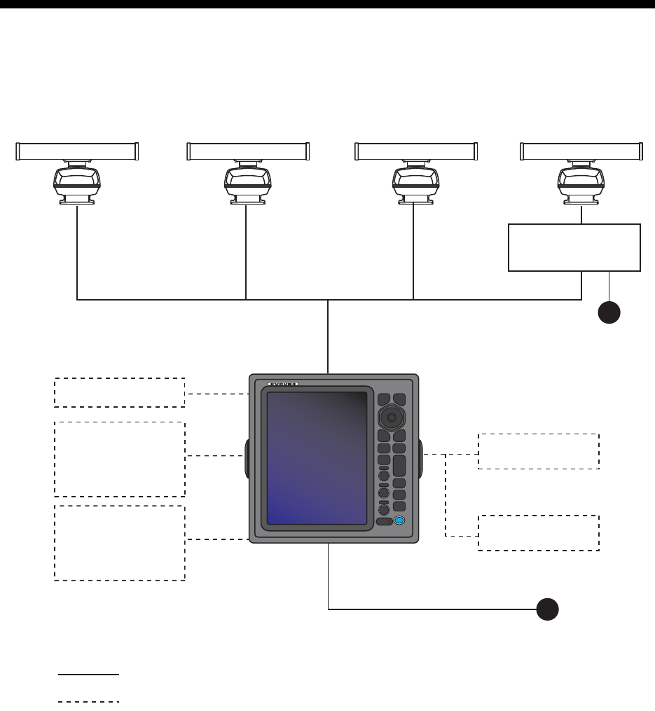
SYSTEM CONFIGURATION
24 VDC
Display unit
RDP-154
External buzzer
Echo sounder
GPS navigator
AIS, etc.
Remote display
: Basic configuration
Heading sensor
Echo sounder
GPS navigator
AIS, etc.
: Optional
Model FR-8065
Antenna Unit
XN-12A-RSB-0070-085A
XN-12A-RSB-0073-085A
XN-13A-RSB-0070-085A
XN-13A-RSB-0073-085A
Model FR-8125
Antenna Unit
XN-12A-RSB-0070-086A
XN-12A-RSB-0073-086A
XN-13A-RSB-0070-086A
XN-13A-RSB-0073-086A
Model FR-8255
Antenna Unit
XN-12A-RSB-0070-087A
XN-12A-RSB-0073-087A
XN-13A-RSB-0070-087A
XN-13A-RSB-0073-087A
24 VDC
Antenna Power Supply
PSU-008
Model FR-8045
Antenna Unit
XN-12A-RSB-0073-088B
XN-13A-RSB-0073-088B
SYSTEM CONFIGURATION
xii
This page is intentionally left blank.

1-1
1. OPERATION
1.1 Controls
The display unit has 16 keys which have labels with their functions, three knob con-
trols and a CursorPad. When you correctly operate this equipment, the unit beeps one
time. If your operation is not correct, the unit beeps three times.
No. Control Description
1MENU Open/close the menu.
2CursorPad Select the menu items and options.
Move the cursor. (Shown like W,S,X
& T in the manual.)
3EBL Measure the bearing to a target.
4OFF CENTER Off-center the display.
5TLL Send the latitude and longitude of a
target to a navigation plotter. Enter an
origin mark at the cursor position on
the radar display.
6GAIN Rotating: Adjust the sensitivity of the
radar receiver.
7A/C SEA Rotating: Reduce the sea clutter.
8A/C RAIN Rotating: Reduce the rain clutter.
6,7,
8
F1,F2, F3 Push: Activate the function given to
the key.
9CANCEL/HL
OFF
Erase the heading line while you press
this key. Cancel the last entry in menu
operation. Cancel the tracking of
ARPA target. Remove data of select-
ed ARPA or AIS target from the data
box. Return one layer in a multiple lev-
el menu.
10 ENTER Save selected menu option. Acquire
an ARPA target. Select the ARPA or
AIS target to display its data.
11 VRM Measure the range to a target.
12 TARGET
ALARM
Set the target alarm, which checks for
the targets in the operator-set area.
13 RANGE Select the detection range.
14 CUSTOM Set the radar controls for one-touch
operation of radar.
15 TRAILS Plot the radar echo movement.
16 STBY/TX Transmit the radar pulses or put the
radar in standby.
17 Brill Short Press: Turn on the power. Adjust
the brilliance.
Long press: Turn off the power.
MENU
CANCEL
HL OFF
ENTER
EBL VRM
OFF
CENTER
TARGET
ALARM
TLL
GAIN
A/C SEA
A/C RAIN
RANGE
+
CUSTOM
TRAILS
STBY
TX
ECONOMY
F1
F2
F3
1
2
3
4
5
B
R
I
L
L
6
7
8
9
11
12
13
14
15
16
17
10
R
B
L
L
I
CANCEL
HL OFF
MENU
EBL VRM
TARGET
ALARM
GAIN
A/C SEA
CUSTOM
TRAILS
STBY
TX
A/C RAIN
ECONOMY
RANGE
OFF
CENTER
TLL
ENTER
1. OPERATION
1-2
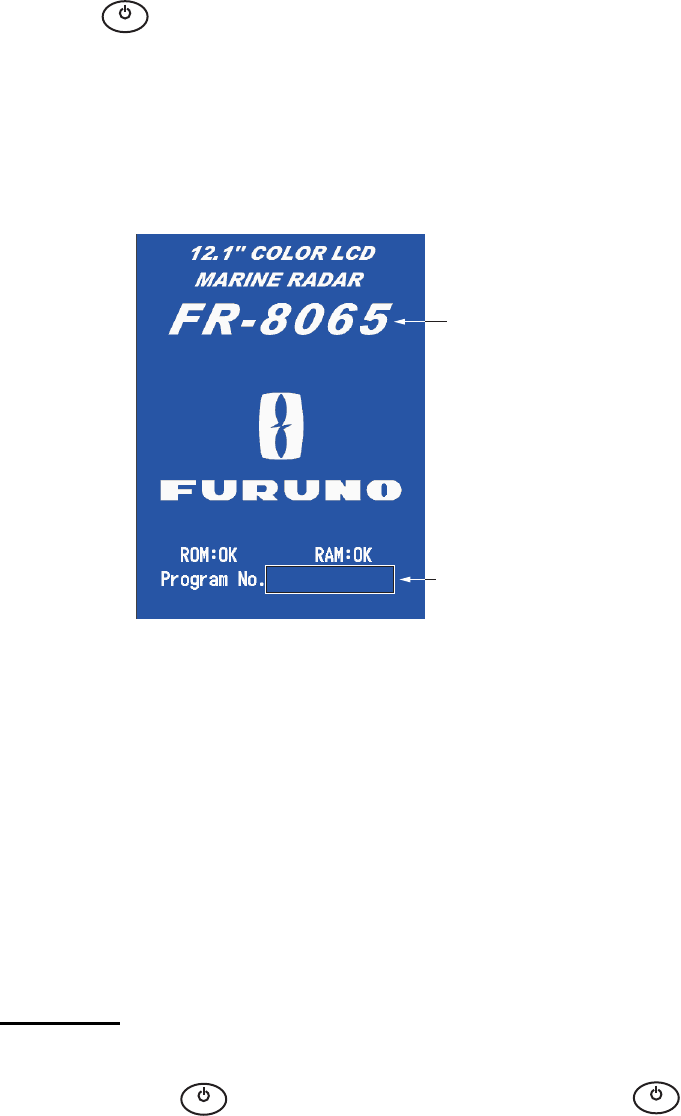
1.2 How to Turn the Radar On/Off and Transmit
Press the key to turn on the radar.To turn off the radar, press and hold the key
until the screen turns off.
When you turn on the power, the initialization screen appears followed by the start-up
screen. The start-up screen shows the model name, program number and the results
of the ROM and RAM check, "OK" or "NG" (No Good). If "NG" appears, contact your
dealer for instruction.
Start-up screen
After the self-tests have completed, the bearing scale and a digital timer appear. The
digital timer counts down the time necessary to warm the magnetron, which transmits
the radar pulses. The time to warm the magnetron is 90 seconds for FR-8045/FR-
8065 and FR-8125 radars, 180 seconds for FR-8255 radar.
After the timer reads 0:00, the STBY screen appears. The STBY screen has three
types. (See paragraph 1.44.2.) The radar is ready to transmit the radar pulses. Press
the STBY/TX key to transmit the radar pulses.
The STBY/TX key switches between standby and transmit. The antenna rotates in
transmit and is stopped in standby. The magnetron gets old with use. To increase the
life of the magnetron, set the radar in standby when you do not use the radar.
Quick start
If the magnetron is still warm, you can get the radar to TRANSMIT without the warm
up time. When the key is turned off by accident, turn on the key within 10
seconds after you turn off the power.
B
R
I
L
L
Model name
appears here.
Program &
version no.
0359307-XX.XX
B
R
I
L
L
B
R
I
L
L
1. OPERATION
1-3
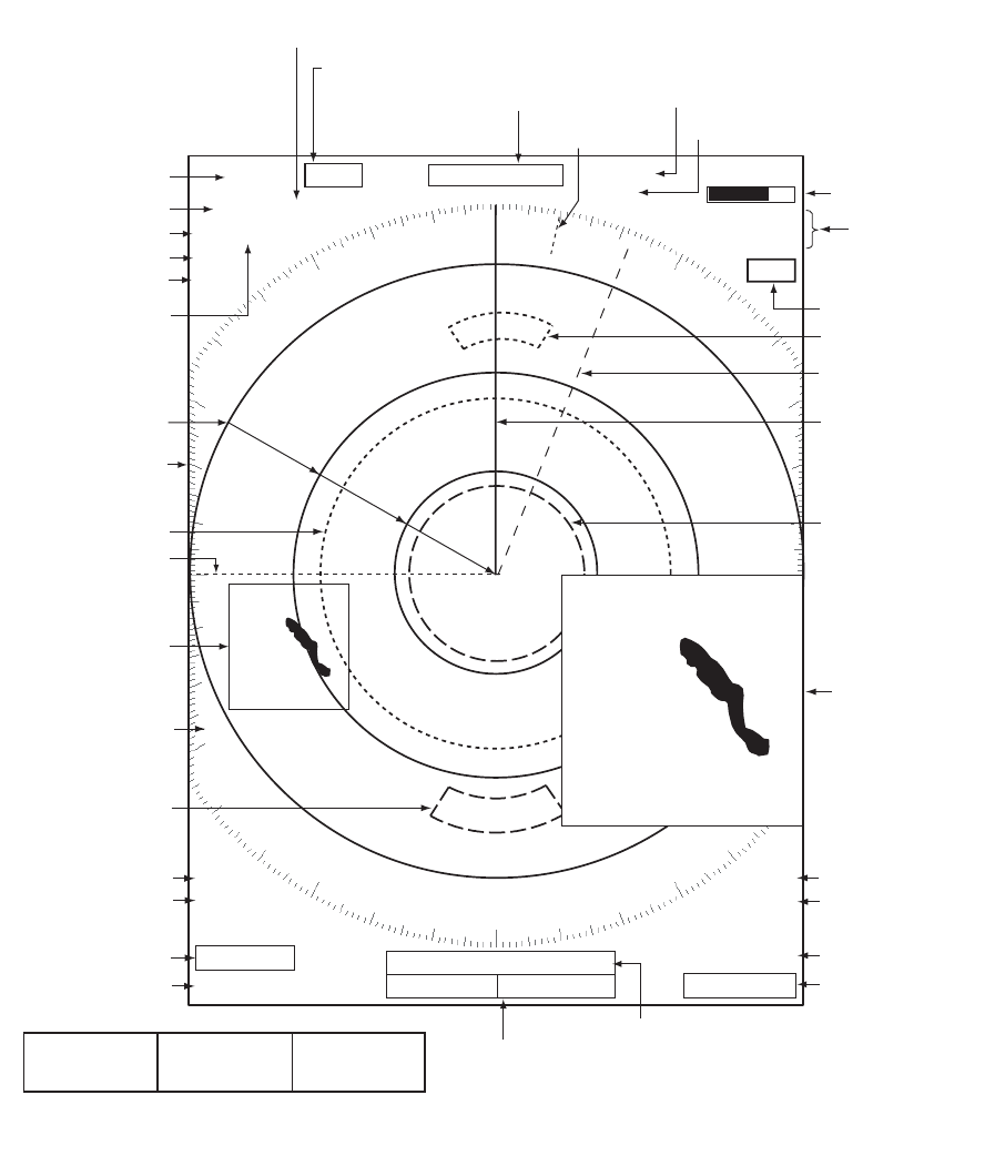
1.3 Display Indications
Display indications
Heading
Nav data: Appears at screen bottom when [Data Box]
in the [Display] menu is set to [Nav] or [All]. Appropriate
sensors required to display nav data.
Cursor data
(Range and bearing or L/L position)
Display mode
Range ring interval
Range
Pulselength
Trail reference
No. 1 EBL bearing
No. 2 EBL bearing
Offcenter
(M: Manual, A: Auto, C: Custom)
North marker
Tuning indicator
Target Alarm 1 (2)
indications
No. 1 VRM range
No. 2 VRM range
WATCHMAN
Target alarm zone 1
Target alarm zone 2
350.0°
TRAIL(T)
15 S
+
1.5
1.5
NM
NM
OFFCENT(A)
WTC
Heading line
Range ring
No. 2 VRM
No. 2 EBL
Zoom window
Zoom cursor
No. 1 EBL
No. 1 VRM
Cursor
Bearing scale
HDG
0.5
SP CS 1
Custom setting
(1 - 3)
H UP
LAT 34°56.123N
LON 135°34.567E
SPEED 12.3KN
LAT 34°56.123N
LON 135°34.567E
TTG 01:00
B RG
14. 8°
RNG 0.876NM
TTG
00:20
OWN SHIP + CURSOR WAYPOINT
TUNEAUTO
ALM1_ACK
ALM2_OUT
SLAVE
Input source
(shown when display
unit functions as
remote display)
IR 1
A/C AUTO
VRM
0.889
NM
0.422
NM
Interference rejector
Auto adjustment of
rain and sea clutters
22.0
°
R
270.0
°
R
ES 1
EAV 1
EBL
Echo stretch
Echo averaging
241.0
°
R
1.592
NM
VECT
TRUE
05:00
Vector time
ZOOM(R)
Zoom indication
+
Trail time
1. OPERATION
1-4
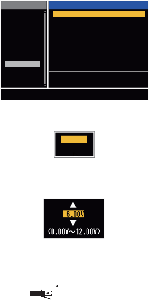
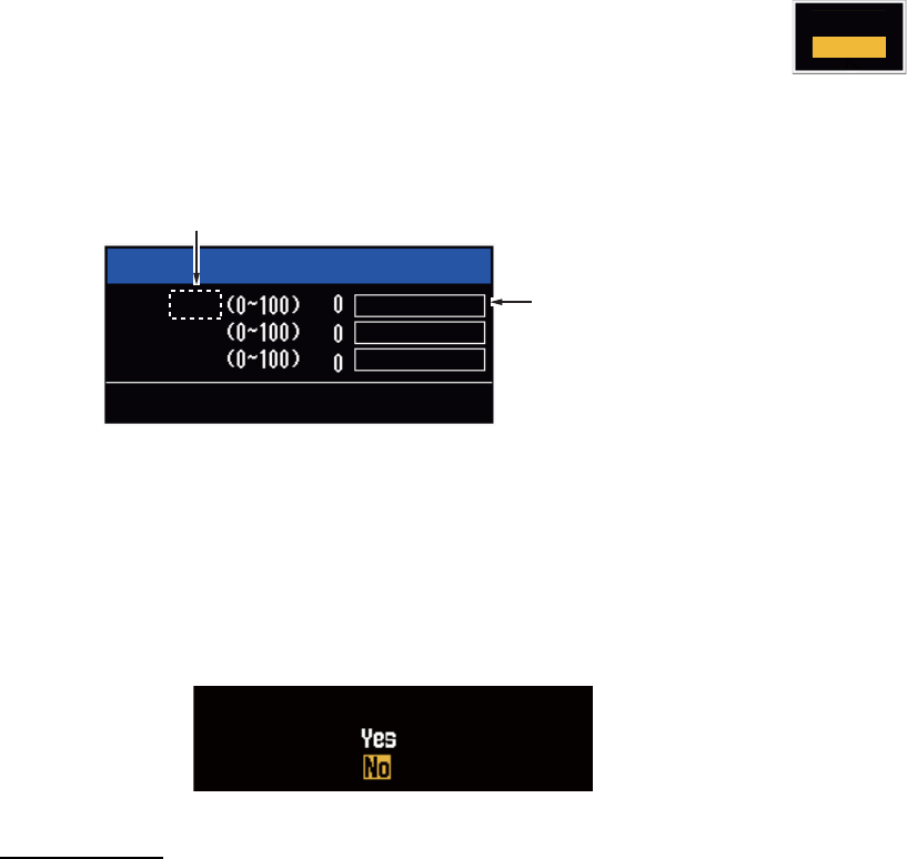
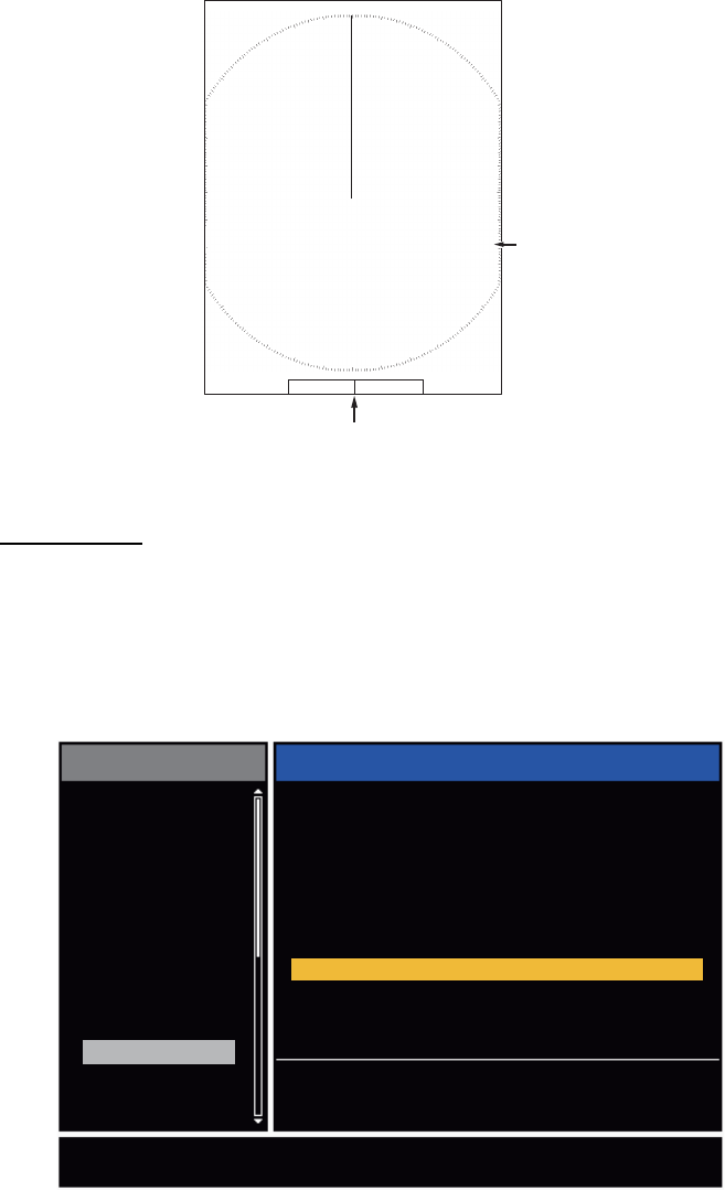
1.4 How to Adjust Display Brilliance, Panel Dimmer
You can adjust the display brilliance and panel dimmer as follows:
1. Press the key to show the [Brill/Panel] dialog box.
Brill/Panel dialog box
2. Press the [ENTER] key (or S, T) to select [Brill] or [Panel].
3. Use W or X to adjust. (For brilliance you can also use the key.)
4. Press the CANCEL/HL OFF key to close the window.
1.5 Menu Description
This FR-8045/FR-8065/FR-8125/FR-8255 series has 15 menus and 6 sub menus.
Below is the basic procedure for menu operation.
1. Press the MENU key to open the menu.
Menu
B
R
I
L
L
Brill/Panel
Min Max
Brill (1~16)16
8
Panel (1~ 8)
Enter Select
CANCEL/HL OFF
Close
B
R
I
L
L
Cursor*
Menu items
and current
settings
Title bar*
*: Title bar in currently controlled column is blue; cursor selection is yellow.
Title bar of inactive column is gray.
Brill/Color
Display
Echo
Custom 1
Custom 2
Custom 3
Alarm
Target Trails
Tuning
Others
Target
Menu Brill/Color
Echo Brill
Rings Brill
Mark Brill
HL Brill
Character Brill
Echo Shading
Display Color
Echo Color
Background Color
: 8
: 4
: 4
: 4
: 4
: 1
: Custom
: Yellow
: Black
[ENTER]: Enter
[MENU] Exit
[CANCEL/HL OFF]: Back
Adjusting brilliance and color
Menu Currently selected menu
Scroll bar (Indicates menus currently not shown in menu
window. Black vertical line indicates location in menu.
You can see the menus and sub menus currently not shown
by using or .)
Guide message
(The simple explanation for
the current menu.)

1. OPERATION
1-5
2. Use S or T to select a menu or sub-menu.The cursor (yellow) in the [Menu] col-
umn indicates the menu currently selected. The menu items in the right-hand win-
dow change according to the menu selected.
Menu Description
[Brill/Color]: Adjust the brilliance and color.
[Display]: Set up the display features.
[Echo]: Adjust the radar echo.
[Custom 1] - [Custom 3]: Adjust the user settings.
[Alarm]: Set up the alarm features.
[Target Trails]: Process the trails of radar targets.
[Tuning]: Adjust the radar tuning.
[Others]: Set up other items.
[Target]: Set up the targets configuration.
[ARPA]: Set up the ARPA targets.
[AIS]: Set up the AIS targets.
[GPS]: Set up the GP-320B (Black-Box GPS).
[System]
[Initial]: Initial Setting.
[Tests]: Diagnostic self test, LCD test and ARPA test. See section 6.7 to 6.9.
[Sector Blanks]: Set sector blanks to prevent the transmission in a certain area.
[Units]: Set up units.
[Installation] and [Factory]: For use by the installer. See Installation Manual.
3. Press the ENTER key to switch the cursor to the menu items column. The cursor
in the menu column now turns gray and the cursor in the menu items column is
yellow. The control moves to the menu items column.
To switch the cursor from the menu items column to the menu column, use the
CANCEL/HL OFF key. The color of the title bar of the active column is blue and
of the inactive column in gray.
4. Use S or T to select a menu item and press the ENTER key. A window with op-
tions for the related menu item appears.
Example windows
5. Use S or T to select an option or numeric value.
6. Press the ENTER key to save your selection. To close the window without saving,
press the CANCEL/HL OFF key.
7. Press the MENU key to close the menu.
Note: The menus on the [IEC] and [Russian-River] types close automatically when
there is no menu operation for 10 seconds, according to IEC regulations. The following
menus and screens are excluded from this regulation:
[Alarm message], [Alarm status], [Tuning Init Adjust], [GPS self test], [GPS satellite
monitor], [System self test], [System LCD pattern], and [Auto installation setup]. The
menus do not close automatically in the [River] or [Sea] configuration.
Display Color options Echo Brill setting window
Day
Night
Twilight
Custom
8
(1~8)
1. OPERATION
1-6
1.6 Tuning
In default, the radar receiver can be tuned automatically after you set the radar to TX.
If you require fine tuning in manual, do the following:
1. Transmit the radar and select the maximum range with the RANGE key.
2. Press the MENU key to open the menu.
3. Use S or T to select [Tuning] and press the ENTER key.
Tuning menu
4. Use S or T to select [Tuning Mode] and press the ENTER key.
Tuning Mode options
5. Use S or T to select [Manual] and press the ENTER key.
6. Use S or T to select [Manual Tuning] and press the ENTER key.
Manual Tuning setting window
7. Use S or T to adjust the tuning while you look at the tuning bar in the upper-right
corner of the display. The best tuning point is where the tuning bar moves to a
maximum value. The vertical bar on the tuning bar shows the tuning voltage.
8. Press the ENTER key.
9. Press the MENU key to close the menu.
Note: If the automatic tuning does not give the correct tuning, run the [Tuning Init Ad-
just] again.
[ENTER]: Enter
[MENU] Exit
[CANCEL/HL OFF]: Back
Menu
Tuning
Tuning Mode : Auto
Manual Tuning : 6.00V
Tuning Init Adjust
Brill/Color
Display
Echo
Custom 1
Custom 2
Custom 3
Alarm
Target Trails
Tuning
Others
Target
Choosing a tuning mode
Auto
Manual
TUNE MAN Tuning method (Manual)
Tuning bar
Vertical bar

1. OPERATION
1-7
1.7 Display Modes
This radar has the display modes shown below. All modes except head up require a
heading signal. The true motion mode additionally requires position data.
Relative Motion (RM)
• [Head Up] (H UP)
• [Course Up] (C UP)
• [North Up] (N UP)
• [True View] (TRUE VIEW)
True Motion
• [True Motion] (TM)
1.7.1 How to select the display mode
1. Press the MENU key to open the menu.
2. Use S or T to select [Display] and press the ENTER key.
Display menu
3. Use S or T to select [Display Mode] and press the ENTER key.
4. Use S or T to select a display mode and press the ENTER key.
5. Press the MENU key to close the menu.
Note: All modes except head up require a heading signal in AD-10 format or NMEA
format. If the heading signal is lost, the mode is changed to head up and the north
marker disappears. The display for heading is XXX.X and the alarm sounds. The mes-
sage "GYRO" (AD-10 format data) or "NMEA_HDG" (NMEA format data) appears in
the alarm message display. To stop the audio alarm, press any key. When the heading
signal is restored, check the heading. To check the heading, press the F3 key. When
the heading signal is restored, the current heading is displayed at the heading indica-
tion.
Menu Display
Brill/Color
Display
Echo
Custom 1
Custom 2
Custom 3
Alarm
Target Trails
Tuning
Target
Others
[ENTER]: Enter
[MENU] Exit
[CANCEL/HL OFF]: Back
Choosing the presentation mode
Display Mode : Head Up
Zoom
Zoom Mode
Offcenter Mode
Save Offcenter
Echo Area
Base Text Display
Data Box
Gain/Sea/Rain Bar
: Off
: Relative
: Normal
: All
Head Up
Course Up
North Up
True Motion
True View
1. OPERATION
1-8
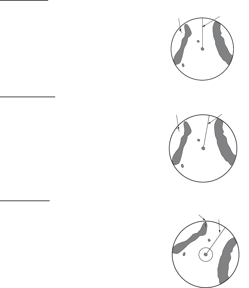
1.7.2 Description of display modes
Head up mode
A display without azimuth stabilization in which the line
that connects the center with the top of the display in-
dicates your heading. Targets are shown at their mea-
sured distances and their directions relative to your
heading. The short dotted line on the bearing scale is
the north marker.
Course up mode
The radar picture is stabilized and displayed with the
currently selected course at the top of the screen.
When you change the heading, the heading line
moves with the course selected. If you select a new
course, select the course up mode again to display
the new course at the top of the display. Targets are
shown at their measured distances and their direc-
tions relative to the set course, which is at the 0-de-
gree position. The heading line moves according to
the yawing and any course change.
North up mode
Targets are shown at their measured distances and
their true (compass) directions from your ship. North is
at the top of the screen. The heading line changes its
direction according to your heading.
Heading line
North marker
Heading line
North marker
Heading line
North marker
1. OPERATION
1-9
True motion mode
Your ship and other objects in motion move with their true
courses and speed. All fixed targets, like landmasses, ap-
pear as fixed echoes in ground stabilized TM. When your
ship reaches a point that is 75% of the radius of the dis-
play, the position is reset. The ship appears at 75% radius
opposite to the extension of the heading line on the dis-
play center. You can manually reset your ship symbol if
you press the OFF CENTER key.
Example: Automatic reset of your ship marker in true motion mode
True view mode
The echoes move in real time according to the change of the heading of your ship. The
heading line is at the top of the screen. When the heading signal is lost, this function
is not available and the display mode automatically changes to the head up mode. The
[Wiper] is not available in this mode (see section 1.31).
Heading li
n
North marker
Heading
line
North
marker
(a) True motion
is selected
(b) Your ship has reached a
point 75% of display radius
(c) Your ship is automatically
reset to 75% of display radius
Heading line
North marker Heading line
North marker
The echoes move
according to the
change of the heading
of your ship during
one sweep.
1. OPERATION
1-10
1.8 How to Select a Range Scale
The selected range scale, range ring interval and pulselength are shown at the upper
left corner on the screen. When an object target comes closer, reduce the range scale
so that the target appears in 50-90% of the display radius.
Use the RANGE key to select range. Press the "+" part of the key to raise the range;
the "-" part to lower the range.
1.9 How to Adjust the Gain (sensitivity)
The gain functions to adjust the sensitivity of the receiver for the best reception. The
gain is adjusted automatically or manually.
1. Press the MENU key to open the menu.
2. Use S or T and select [Echo] and press the ENTER key.
3. Use S or T to select [Gain Mode] and press the ENTER key.
4. Use S or T to select [Auto] or [Manual] and press the ENTER key.
the window for Gain/Sea/Rain indicator shown below appears. This
window closes automatically in the [River] or [Sea] mode when there
is no menu operation for ten seconds. [Auto] is for adjusting the gain automatical-
ly. For [Manual] go to "Manual mode" below.
Gain/Sea/Rain indicator
5. Press the CANCEL/HL OFF key to close the window.
6. Press the MENU key to close the menu.
Note: To adjust the gain finely in [Auto] mode, rotate the GAIN knob. The confirmation
message appears. If you select [Yes] the mode changes to [Manual] mode. Rotate the
Gain knob to adjust the gain.
Manual mode
1. Rotate the GAIN knob to adjust the gain so that weak noise appears on all of the
screen. If the gain is too low, weak echoes are erased. If the gain is too high, the
background noise hides weak targets.
2. Press the CANCEL/HL OFF key to close the window.
Manual
Auto
Gain/Sea/Rain
GAIN MAN
SEA
RAIN
MAN
MAN
[CANCEL/HL OFF: Close
AUTO: Auto, MAN: Manual
Gain setting bar
Are you sure to change to manual mode?

1. OPERATION
1-11
1.10 How to Reduce the Sea Clutter
The reflected echoes from the waves appear around your ship and have the name
"sea clutter". The sea clutter extends according to the height of waves and antenna
above the water. When the sea clutter hides the targets, use the A/C SEA control to
reduce the clutter, either manually or automatically.
Auto mode
1. Press the Menu key to open the menu.
2. Use S or T to select [Echo] and press the ENTER key.
3. Use S or T to select [Sea Mode] and press the ENTER key.
4. Use S or T to select [Auto] or [Manual] and press the ENTER key. The window
for Gain/Sea/Rain indicator appears. (Refer to the illustration of step 4 in
section 1.9). If you selected [Auto], go to step 5. For [Manual], go to "Manual
mode" below.
5. Press the CANCEL/HL OFF key to close the window. [Auto] is used to reduce the
sea clutter automatically. If the sea clutter is strong while cruising along a coast-
line in the [Auto] mode, go to step 6. If not, go to step 9.
6. Use S or T to select [Auto Sea] and press the ENTER key.
7. Use S or T to select [Coastal] or [Advanced] then press the ENTER key. The win-
dow for Gain/Sea/Rain indicator appears for confirmation.
[Coastal]: Suppress both land and sea clutter. For cruising along a coastline.
[Advanced]: Automatically identify land echoes from sea reflections to suppress
only sea reflections. Use this mode for general use.
8. Press the CANCEL/HL OFF key to close the menu.
9. Press the MENU key to close the menu,
Note: When you want to adjust the sea clutter finely in [Auto] mode, rotate the
A/C SEA knob. The confirmation window appears. If you select [Yes], the mode
changes to [Manual] mode. Rotate the A/C SEA knob to adjust the sea clutter.
Confirmation message
Manual mode
1) Rotate the A/C SEA knob to reduce the sea clutter.
Note: When the setting of the A/C SEA control is correct, the clutter is broken into
small dots, and small targets become identified. If the setting is not enough, targets
are hidden in the clutter. If the setting is higher than necessary, both sea clutter
and targets disappear from the display. Normally adjust the control until the clutter
has disappeared to leeward, but a small amount of the clutter is visible windward.
Coastal
Advanced
Are you sure to change to manual mode?
1. OPERATION
1-12
2) Press the CANCEL/HL OFF key to close the window.
1.11 How to Reduce the Rain Clutter
The reflections from the rain or snow appear on the screen. These reflections have the
name "rain clutter". When the rain clutter is strong, targets in the rain clutter are hidden
in the clutter. Reflections from the rain clutter are easily identified from true targets by
their wool-like appearance.The A/C RAIN control, like the A/C SEA control, adjusts
the receiver sensitivity, but in longer range. If the setting is high, the rain clutter is more
reduced. The rain control breaks the continuous display of rain or snow reflections into
a random pattern. When the rain clutter hides the targets, adjust the rain control (au-
tomatic or manual) to reduce the clutter.
Auto mode
1. Press the MENU key to open the menu.
2. Use S or T to select [Echo] and press the ENTER key.
3. Use S or T to select [Rain Mode] and press the ENTER key.
4. Use S or T to select [Auto] or [Manual] then press the ENTER key. The window
for Gain/Sea/Rain indicator appears (refer to the illustration of step 4 at
section 1.9). If you selected [Auto], go to step 5. For [Manual], go to "Manual
mode" below.
5. Press the CANCEL/HL OFF key to close the window.
6. Use S or T to select [Auto Rain] and press the ENTER key.
7. Use S or T to select [Calm], [Moderate] or [Rough] then press the ENTER key.
The window for Gain/Sea/Rain indicator appears for confirmation.
[Calm]: For light rain
[Moderate]: When you cannot reduce the rain clutter with [Calm] mode
[Rough]: For heavy rain
8. Press the CANCEL/HL OFF key to close the window.
9. Press the MENU key to close the menu.
Note: When you want to adjust the rain clutter finely in [Auto] mode, rotate the A/C
RAIN knob. The confirmation message appears. If you select [Yes], the mode chang-
es to [Manual] mode. Rotate the A/C RAIN knob to adjust the rain clutter.
A/C SEA control adjusted;
sea clutter reduced
Sea clutter at
screen center
Calm
Moderate
Rough
1. OPERATION
1-13
Manual mode
1. Rotate the A/C RAIN knob to reduce the rain clutter.
2. Press the CANCEL/HL OFF key to close the window.
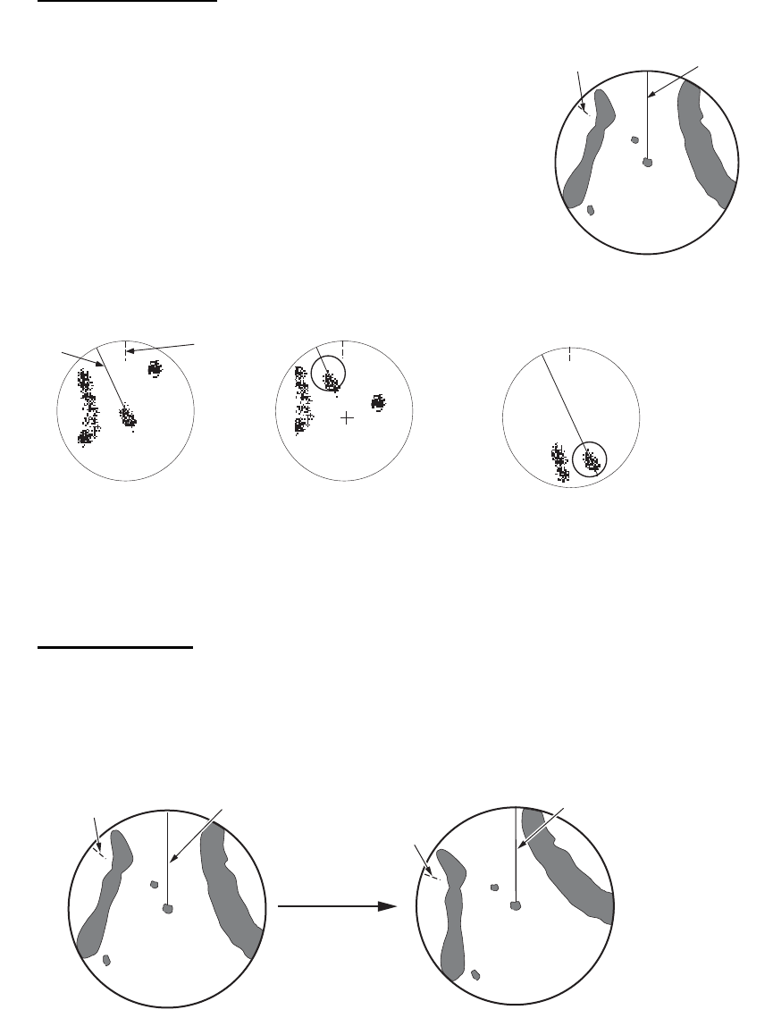
1.12 Automatic Adjustments of Sea and Rain Clutters
When you can not correctly reduce the sea clutter or rain clutter with the related con-
trol, turn on the automatic anti-clutter feature. When this feature is turned on,
"A/C AUTO" appears at the lower-right corner.
1. Press the MENU key to open the menu.
2. Use S or T to select [Echo] and press the ENTER key.
3. Use S or T to select [A/C Auto] and press the ENTER key.
4. Use S or T to select [Off] or [On] then press the ENTER key.
5. Press the MENU key to close the menu.
Caution on use
• Echoes that cover wide areas (like land and islands) can become smaller when the
[A/C Auto] is used.
• When [A/C Auto] is active, the strength of a target in sea clutter or rain clutter can
be lower than actual strength. In this case change to manual A/C SEA and manual
A/C RAIN and adjust the picture.
Rain clutter at
screen center
A/C RAIN control adjusted;
rain clutter reduced
A/C Auto: Off A/C Auto: On
:£:¸:Å:»
Land
:£:¸:Å:»
Target
1. OPERATION
1-14
1.13 Cursor
The cursor functions to find the range and bearing (default function) to a target or the
latitude and longitude position of a target. Use the CursorPad to move the cursor into
position and read the cursor data at the screen bottom.
Cursor data
You can show the cursor data as range and bearing (from your ship to the cursor) or
latitude and longitude. Position and heading signal are required.
1. Press the MENU key to open the menu.
2. Use S or T to select [Others] and press the ENTER key.
Others menu
Cursor data
(range and bearing,
or latitutde and longitude)
110.1
° R
0.488
NM
NM
0.5
Cursor
+
+
Brill/Color
Display
Echo
Custom 1
Custom 2
Custom 3
Alarm
Target Trails
Tuning
Target
Others
Menu
[ENTER]: Enter
[MENU] Exit
[CANCEL/HL OFF]: Back
F1 Setup
Cursor Position : Rng/Brg
F2 Setup
F3 Setup
WPT Mark
EBL Reference
VRM Unit
TLL Key Mode
: Gain Mode
: Sea Mode
: A/C Auto
: Off
: Relative
: NM
: TLL Output
Choosing display mode of cursor position
Others
1. OPERATION
1-15
3. Use S or T to select [Cursor Position] and press the ENTER key.
Cursor Position options
4. Use S or T to select [Rng/Brg] (Range/Bearing) or [Lat/Lon] (Latitude/Longitude)
then press the ENTER key. (When the navigation data box display is set to [Nav]
or [All] in the [Display] menu, cursor latitude and longitude position cannot be dis-
played in the cursor data box.)
5. Press the MENU key to close the menu.
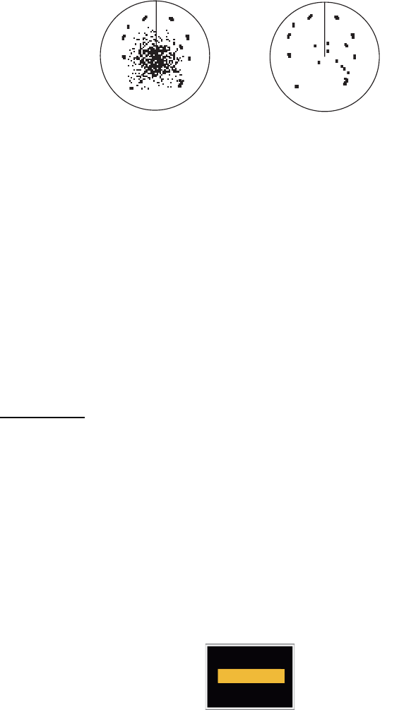
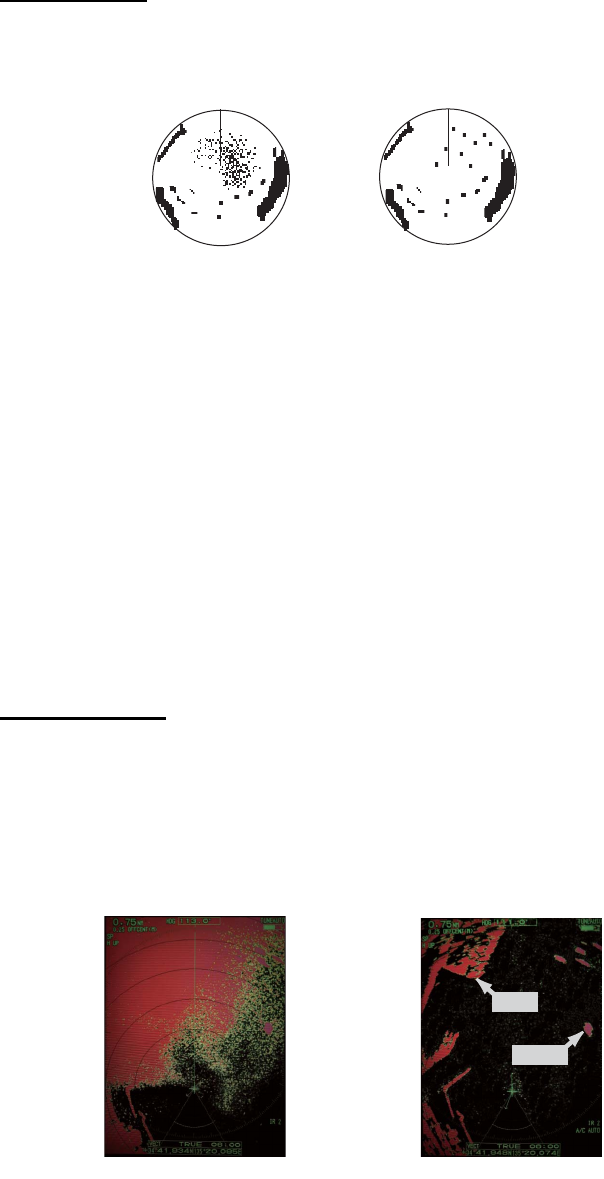
1.14 Interference Rejector
The radar interference can occur when your ship is near the radar of another ship that
operates on the same frequency band with your radar. The interference shows on the
screen as many bright dots. The dots can be random or in the shape of dotted lines
that run from the center to the edge of the display. You can identify the interference
from the normal echoes, because the interference does not appear in the same loca-
tion at the next antenna rotation. When this feature is turned on, "IR 1", "IR 2" or "IR
3" appears at the lower-right corner.
Interference
1. Press the MENU key to open the menu.
2. Use S or T to select [Echo] and press the ENTER key.
3. Use S or T to select [Int Rejector] and press the ENTER key.
Indication at the lower-right corner of the display
4. Use S or T to select [Off], [1], [2] or [3] then press the ENTER key. [3] removes
the interference the most.
5. Press the MENU key to close the menu.
Note: When there is no interference, turn off the interference rejector so you do not
miss the small targets.
Rng/ Brg
Lat/Lon
Off
1
2
3
IR 1
IR 2
IR 3

1. OPERATION
1-16
1.15 How to Measure the Range to a Target
You can measure the range to a target in three methods. You can use the fixed range
rings, the cursor (if set to measure range and bearing) and the VRM (Variable Range
Marker).
Use the fixed range rings to get a rough estimate of the range to a target. The fixed
range rings are the concentric solid circles about your ship. The number of rings
changes with the selected range scale. The interval of the range ring is displayed at
the upper-left corner of the screen. Count the number of rings between the center of
the display and the target. Check the range ring interval and measure the distance of
the echo from the nearest ring.
1.15.1 How to adjust range ring brilliance
1. Press the MENU key to open the menu.
2. Use S or T to select [Brill/Color] and press the ENTER key.
3. Use S or T to select [Rings Brill] and press the ENTER key.
Brill/Color menu
4. Use S or T to select an option and press the ENTER key. [4] is the brightest. [Off]
turns off the range rings.
Rings/Brill options
5. Press the MENU key to close the menu.
: 8
: 4
: 4
: 4
: 1
: Custom
: Yellow
: Black
[ENTER]: Enter
[MENU] Exit
[CANCEL/HL OFF]: Back
Adjusting range ring brilliance
Menu Brill/Color
Echo Brill
Mark Brill
HL Brill
Character Brill
Echo Shading
Display Color
Echo Color
Background Color
Rings Brill : 4
Brill/Color
Display
Echo
Custom 1
Custom 2
Custom 3
Alarm
Target Trails
Tuning
Others
Target
Off
1
2
3
4
1. OPERATION
1-17
1.15.2 How to measure the range with a VRM
There are two VRMs, No. 1 and No. 2. The VRMs are dashed rings so that you can
identify the rings from the fixed range rings. You can identify VRM 1 from VRM 2 by
different lengths of dashes. The dashes of the No. 1 VRM are shorter than those of
the No. 2 VRM.
1. Press the VRM key to display either of the VRMs. Press the VRM key to change
the active VRM between No. 1 and No. 2. The indication of the currently active
VRM is in a rectangle.
2. Use the CursorPad to align the Variable Range Marker with the inner edge of the
target. Read the distance at the lower-right corner of the screen. Each VRM re-
mains at the same geographical distance when you operate the RANGE key. The
size of the VRM ring changes in proportion to the selected range scale.
3. Press the ENTER key to anchor the VRM.
4. To erase a VRM, press the VRM key to activate the VRM and press the CANCEL/
HL OFF key.
1.15.3 How to select VRM unit
You can select the unit of measurement used by the VRM. The selections are nautical
miles (NM), kilometers (KM), statute miles (SM), kiloyard (KYD) or nautical miles and
yards (NM&YD). The cursor range unit is also changed when the VRM unit is
changed.
1. Press the MENU key to open the menu.
2. Use S or T to select [Others] and press the ENTER key.
VRM 1
Cursor range and bearing
VRM 2
Target
+
VRM
5.044NM
2.082NM
Cursor (+)
VRM 1 range
VRM 2 range
+
The currently active VRM
is in a rectangle.
37.4
º R
5.044
NM
VECT
TRUE
05:00
1. OPERATION
1-18
3. Use S or T to select [VRM Unit] and press the ENTER key.
4. Use S or T to select the unit and press the ENTER key.
5. Press the MENU key to close the menu.
1.16 How to Measure the Bearing to a Target
Use the Electronic Bearing Line (EBL) to take a bearing of a target. There are two
EBLs, No. 1 and No. 2. Each EBL is a straight dashed line from the center of the
screen to the edge. The dashes of the No. 1 EBL are shorter than those of the No. 2
EBL.
1.16.1 How to measure the bearing with an EBL
1. Press the EBL key to display either of the EBLs. Press the EBL key to change the
active EBL between No. 1 and No. 2. The indication of the currently active EBL is
in a rectangle.
2. Use the CursorPad to put the EBL on the center of the target. Read the bearing
at the lower-left corner of the screen.
3. Press the ENTER key to anchor the EBL.
4. To erase an EBL, press the EBL key to activate the EBL and press the CANCEL/
HL OFF key.
How to measure the bearing with the EBL
NM: 0.1 NM or above
YD: Less than 0.1 NM
NM
KM
SM
KYD
NM&YD
+
EBL
270.0
°
R
45.0
°
R45.0
°
R
5.044
NM
+
EBL 1 EBL 2
Cursor range and bearing
Target
Cursor (+)
The currently active EBL
is in a rectangle.
EBL 1 bearing
EBL 2 bearing
VECT
TRUE
05:00
1. OPERATION
1-19
1.16.2 EBL reference
"R" (relative) follows the EBL indication if the bearing is relative to the heading of your
ship. "T" (true) follows the EBL indication if the bearing is in reference to the north. You
can select relative or true in the head up and true view modes. The bearing indication
is true in all other modes. True bearing requires a heading sensor.
1. Press the MENU key to open the menu.
2. Use S or T to select [Others] and press the ENTER key.
3. Use S or T to select [EBL Reference] and press the ENTER key.
4. Use S or T to select [Relative] or [True] then press the ENTER key.
5. Press the MENU key to close the menu.
1.17 How to Measure the Range and Bearing Between
Two Targets
You can move the origin of the EBL to measure the range and bearing between two
targets.
1. Press the EBL key to select the bearing indication of EBL 1 or EBL 2. The indica-
tion of the currently active EBL is in a rectangle.
2. Use the CursorPad to put the cursor on the center of the target A.
3. Press the OFF CENTER key to move the origin of the EBL to the location selected
at step 2.
4. Use the CursorPad to put the cursor on the center of the target B.
5. Press the VRM key to display the VRM having the same number as the EBL acti-
vated at step 1. The indication of the currently active VRM is in a rectangle.
6. Use the CursorPad to set the VRM on the inner edge of the target B.
7. Read the bearing and range indica-
tions at the bottom of the screen.
Note: When you press the OFF CEN-
TER key in EBL operation, the origin of
an EBL moves between the screen cen-
ter and cursor location. To return the ori-
gin of an EBL to the screen center, press
the ENTER key when the origin of an
EBL is on the screen center.
Relative
True
EBL origin
+
+
Target B
Range/bearing between
targets A and B Range/bearing between
targets C and D
EBL 2
VRM 2
EBL 1
VRM 1
EBL
45.0
°
R
327.0
°
R
VRM
0.550NM
0.550NM
Target A Target D
Target C

1. OPERATION
1-20
1.18 How to Select a Pulselength
The pulselength in use appears at the upper-left position on the screen. The pulse-
lengths are set to each range scale and custom setup. You can change the pulse-
length on the 1.5 nm, 1.6 nm, 3 nm or 3.2 nm range with the following procedure.
Pulselength cannot be changed on other ranges. (You can change the pulselength on
the 2 nm or 4 nm range in the [Russian-River] mode.) Use a longer pulse when your
purpose is long range detection. Use a shorter pulse when the resolution is important.
Note: Press the CUSTOM key several times to activate the [Echo] menu until the [CS
1] (2, 3) indication (custom setting) disappears from the screen. See the illustration in
section 1.3.
1. Press the MENU key to open the menu.
2. Use S or T to select [Echo] and press the ENTER key.
Echo menu
3. Use S or T to select [Pulse Length] and press the ENTER key
Pulse Length options
4. Use S or T to select [Short] or [Long] then press the ENTER key. The pulse-
length indication at the upper-left corner changes according to your selection as
shown below.
1.5 nm or 1.6 nm (or 2 nm in the [Russian-River] mode): "SP" for [Short] pulse,
"MP" for [Long] pulse
3 nm or 3.2 nm (or 4 nm in the [Russian-River] mode): "MP" for [Short] pulse, "LP"
for [Long] pulse
5. Press the MENU key to close the menu.
[ENTER]: Enter
[MENU]: Exit
[CANCEL/HL OFF]: Back
Brill/Color
Display
Echo
Custom 1
Custom 2
Custom 3
Alarm
Target Trails
Tuning
Target
Others
Menu Echo
Sea Mode
Auto Sea
Rain Mode
Auto Rain
A/C Auto
Echo Stretch
Echo Average
Noise Rejector
: Manual
: Advanced
: Manual
: Moderate
: Off
: Off
: Off
: Off
Pulse Length : Short
Choosing a pulse length
Short
Long
1. OPERATION
1-21
1.19 Target Alarm
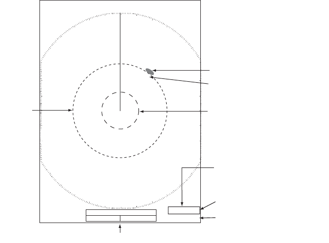
The target alarm looks for targets (ship, landmass, etc.) in the area you set. When a
target enters or exits the alarm area, audiovisual alarms are released.
1.19.1 How to set a target alarm zone
The following procedure shows you how to set a target alarm zone.
1. Press the TARGET ALARM key to activate ALARM 1 or ALARM 2. Press the
TARGET ALARM key to change the active ALARM between No. 1 and No. 2. The
indication of the currently active ALARM is in a rectangle at the upper-right corner
of the screen.
2. Use the CursorPad to move the cursor to the position A and press the ENTER
key.
3. Move the cursor to the position B and press the ENTER key. The rectangle that
shows alarm status indication at the upper-right corner of the screen disappears.
(See figure below)
Note 1: To set a 360-degree guard zone, set the position B in the same bearing as the
position A.
Note 2: When the target alarm zone is not within the range in use, the indica-
tion"ALM1(or 2)_RNG" replaces "ALM1(or 2)_IN(or OUT)" in the alarm status area.
(When the target alarm zone is within the range of full off-centering, the indication
does not change.) Select a range which displays the target alarm zone.
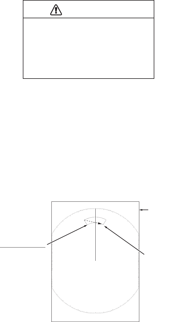
CAUTION
CAUTION
· Do not depend on the alarm as the only
means to detect possible collision
situations.
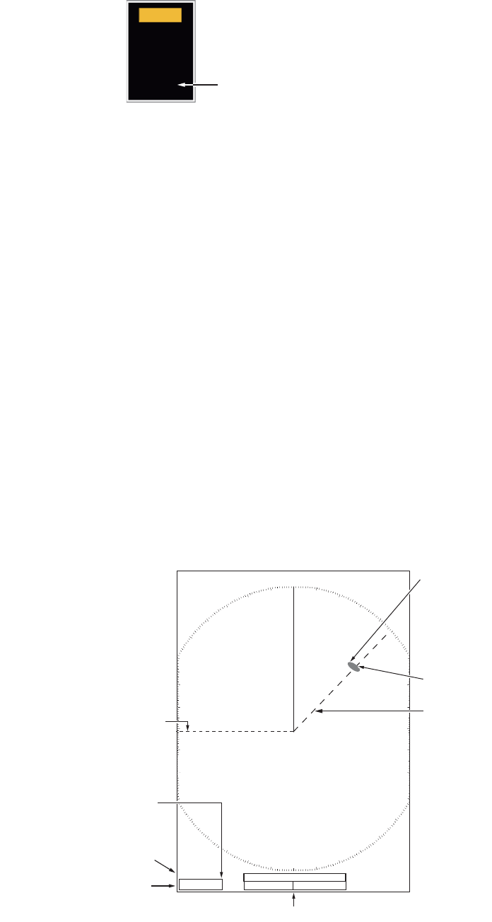
· Adjust the A/C SEA, A/C RAIN and GAIN
controls correctly so that the alarm
system does not miss the target echoes.
Cursor
+
Target alarm zone 1
(Length of dash
and interval for
alarm zone 2 are
longer than alarm
zone 1.)
AB
Alarm status
ALM1_IN
ALM2_OUT
1. OPERATION
1-22
1.19.2 How to stop the audio alarm
When a target enters (or exits) the target alarm zone, the target flashes and the alarm
sounds. The alarm message appears at the bottom of the screen. To stop the audio
alarm, press any key. When the target enters (or exits) the target alarm zone again,
the audio alarm sounds.
1.19.3 How to select the alarm type
You can set the target alarm to activate against targets which enter or exit the alarm
zone.
In and Out target alarms
1. Press the MENU key to open the menu.
2. Use S or T to select [Alarm] and press the ENTER key.
Alarm menu
3. Use S or T to select [Target Alarm 1] or [Target Alarm 2] then press the ENTER
key.
Target Alarm options
4. Use S or T to select [In] or [Out].
[In]: When the targets enter a target alarm zone, the alarm sounds.
[Out]: When the targets exit a target alarm zone, the alarm sounds.
5. Press the ENTER key followed by the MENU key.
“In” target alarm
“Out” target alarm
[ENTER]: Enter
[MENU]: Exit
[CANCEL/HL OFF]: Back
Brill/Color
Display
Echo
Custom 1
Custom 2
Custom 3
Alarm
Target Trails
Tuning
Target
Others
Menu Echo
Choosing the type (in/out) of target alarm 1
Target Alarm 1
Target Alarm 2
Alarm Level
Watchman
Panel Buzzer
Alarm Status
: In
: In
: Med
: Off
: On
External Buzzer : On
In
Out

1. OPERATION
1-23
1.19.4 How to sleep a target alarm temporarily
When you do not require a target alarm temporarily, you can sleep the target alarm.
The alarm zone remains on the screen, but, any targets that enter or exit the alarm
zone do not trigger the audio and visual alarms.
1. Press the TARGET ALARM key to select the ALARM 1 or ALARM 2 indication at
the upper-right corner on the screen. The selected indication is in a rectangle.
2. Press the CANCEL/HL OFF key. The alarm indication now shows "ALM1(or
2)_ACK".
To activate a sleeping target alarm zone, press the TARGET ALARM key to select the
ALARM 1 or ALARM 2 and press the ENTER key. The alarm indication then changes
to "ALM1(or 2)_IN(or OUT)".
1.19.5 How to deactivate a target alarm
1. Press the TARGET ALARM key to select the ALARM 1 or ALARM 2 indication at
the upper-right corner on the screen. The selected indication is in a rectangle.
2. Press the CANCEL/HL OFF key. The alarm indication now shows "ALM1(or
2)_ACK".
3. Press the TARGET ALARM key. The alarm indication "ALM1(or 2)_ACK" is
shown in a dashed-line rectangle.
4. Press the CANCEL/HL OFF key. The target alarm zone and the alarm indication
are erased from the screen.
1.19.6 How to select the target strength which triggers a target alarm
You can select the target strength which triggers the target alarm as follows:
1. Press the MENU key to open the menu.
2. Use S or T to select [Alarm] and press the ENTER key.
3. Use S or T to select [Alarm Level] and press the ENTER key.
4. Use S or T to select the echo strength level.
5. Press the ENTER key followed by the MENU key.
1.19.7 How to turn the buzzer on/off
You can turn on/off the panel buzzer or external buzzer for target alarms. The panel
buzzer is for this equipment. The external buzzer is for the optional buzzer, which is
connected to this equipment to give the target alarm at a remote location.
1. Press the MENU key to open the menu.
2. Use S or T to select [Alarm] and press the ENTER key.
3. Use S or T to select [Panel Buzzer] (or [External Buzzer] for optional
buzzer) and press the ENTER key.
4. Use the S or T to select [On] or [Off] then press the ENTER key.
5. Press the MENU key to close the menu.
Low
Med
High
Off
On

1. OPERATION
1-24
1.20 How to Off-center the Display
You can off-center your ship position to expand the view field without selecting a larger
range scale. The display can be off-centered manually, or automatically according to
speed of the ship.
Note: Off-centering is not available in the true motion mode and the 64 NM range
scale or higher.
1.20.1 How to select the off-center mode
1. Press the MENU key to open the menu.
2. Use S or T to select [Display] and press the ENTER key.
3. Use S or T to select [Offcenter Mode] and press the ENTER key.
Offcenter Mode options
4. Use S or T to select [Manual], [Custom] or [Auto] then press the ENTER key.
Press the ENTER key to change between on and off.
5. After setting all options, use the T to select [EXIT? YES] and press the ENTER
key.
6. Press the MENU key to close the menu.
1.20.2 Off-center the display
Press the OFF CENTER key to move your ship position. When you press the OFF
CENTER key continuously, the mode changes in the sequence of OFF → Manual →
Custom → Auto → OFF → Manual → ... (the options available depend on setting se-
lected at step 4 in section 1.20.1). When off-centering is active, "OFFCENT(M)",
"OFFCENT(C)" or "OFFCENT(A)" appears at the upper-left corner on the display.
Manual (Indication: "OFFCENT(M)")
You can move your ship position to the current cursor position on all modes except
true motion, within 75% of the available display area.
1. Press the OFF CENTER key several times until the off-center indication disap-
pears.
2. Put the cursor in the position to off-center the display.
3. Press the OFF CENTER key several times until the indication "OFFCENT(M)" ap-
pears.
Manual
Custom
Auto
EXIT? YES
On
Off
Off
Press the ENTER key
to change between
on and off.

1. OPERATION
1-25
Custom (Indication: "OFFCENT(C)")
You can move your ship position to the position which you pre-set. Follow the proce-
dure shown below to register the cursor position.
1. Press the OFF CENTER key several times until the off-center indication disap-
pears.
2. Put the cursor on the position where to off-center the display.
3. Press the OFF CENTER key several times until the indication "OFFCENT(M)" ap-
pears.
4. Press the MENU key to open the menu.
5. Use S or T to select [Display] and press the ENTER key.
6. Use S or T to select [Save Offcenter] and press the ENTER key. The message
"Complete" appears.
7. Press any key to close the message window.
8. Press the MENU key to close the menu.
To change the mode to custom, press the OFF CENTER key several times until the
indication "OFFCENT(C)" appears.
Auto (Indication: "OFFCENT(A)")
The amount of automatic move is calculated according to speed of the ship. The max-
imum amount is 75% of the range in use. The formula to calculate automatic shift is
shown below.
If the offcenter speed setting is 15 knots and the speed of the ship is 10 knots, for ex-
ample, the amount of move at the stern of your ship will be 50% of the available display
area.
How to select offcenter speed
1. Press the MENU key to open the menu.
2. Use S or T to select [Initial] sub menu in [System] menu and press the ENTER
key.
3. Use S or T to select [Offcenter Speed] and press the ENTER key.
Offcenter Speed setting window
4. Use S or T to select the speed to use and press the ENTER key.
5. Press the MENU key to close the menu.
Offcenter speed setting
X 0.75 = Amount of move (%)
Speed of ship
15kn
(1kn~99kn)

1. OPERATION
1-26
1.21 Zoom
The zoom function expands the length and width of a selected target as much as twice
its normal size, in the zoom window. You select the target to zoom with the zoom cur-
sor.
The ARPA and AIS symbols can be displayed in the zoom window, but are not
zoomed. You can process ARPA and AIS targets that are in the zoom window, in the
same method as on the normal radar display.
There are three types of zoom.
[Relative]: The zoom cursor is fixed to the range and bearing from your ship.
[True]: The zoom cursor is fixed to a set geographical position.
[Target]: The zoom cursor is fixed to the zoomed AIS ARPA target.
1.21.1 Zoom mode
You can select the zoom mode from [Relative], [True] or [Target].
1. Press the MENU key to open the menu.
2. Use S or T to select [Display] and press the ENTER key.
3. Use S or T to select [Zoom Mode] and press the ENTER key.
Zoom Mode options
4. Use S or T to select [Relative], [True] or [Target] then press the ENTER key.
Note: True zoom mode requires a heading signal and position data. If either sig-
nal is lost, true zoom mode is cancelled.
5. Press the MENU key to close the menu.
1.21.2 How to zoom
Relative or True zoom mode
1. Use the CursorPad to put the cursor on the position required.
2. Press the MENU key to open the menu.
3. Use S or T to select [Display] and press the ENTER key.
4. Use S or T to select [Zoom] and press the ENTER key.
Zoom options
5. Use S or T to select [On] and press the ENTER key. The ZOOM indication ap-
pears at the upper-left corner on the screen. The zoom window and the zoom cur-
sor also appear (see the illustration on the next page). To quit the zoom, select
[Off] instead of [On] and press the ENTER key.
6. Press the MENU key to close the menu.
Relative
True
Target
Off
On
1. OPERATION
1-27
Target zoom mode
The zoom window can display the ARPA or AIS target, as shown below.
ARPA: The symbol is enlarged twice its normal size.
AIS: The symbol is shown inside a broken square. (The symbol is not enlarged.)
The zoom cursor moves with the ARPA or AIS target.
Note: If neither ARPA nor AIS target is selected, the message "NO TARGET." ap-
pears. Press any key to erase the message.
1. Press the MENU key to open the menu.
2. Use S or T to select [Display] and press the ENTER key.
3. Use S or T to select [Zoom] and press the ENTER key.
4. Use S or T to select [On] and press the ENTER key.
The ZOOM indication appears at the upper-left corner on the screen. The zoom
window and the zoom cursor also appear (see the following illustration). To quit
the zoom, select [Off] instead of [On] and press the ENTER key.
5. Press the MENU key to close the menu.
1.5
1.5
NM
NM
Zoom window
255.5
°
R
1.094
NM
ZOOM(T)
+
Zoom cursor
Zoom indication
VECT
TRUE
05:00
+
1.5
1.5
NM
NM
255.5
°
R
1.094
NM
ZOOM(T)
+
VECT
TRUE
05:00
+
Relative or True zoom mode
(example: true zoom)
Target zoom mode
(example: AIS)
999999000
999999000

1. OPERATION
1-28
1.22 Echo Stretch
The echo stretch feature enlarges the targets in the range and bearing directions to
make the targets easier to see. This feature is available on any range. There are three
levels of echo stretch, [1], [2] and [3]. [3] enlarges the targets the most.
Note: The echo stretch enlarges the targets, sea and rain clutters, and radar interfer-
ence. Correctly adjust the sea clutter, rain clutter and radar interference before you ac-
tivate the echo stretch.
1. Press the MENU key to open the menu.
2. Use S or T to select [Echo] and press the ENTER key.
3. Use S or T to select [Echo Stretch] and press the ENTER key.
Echo Stretch options
4. Use S or T to select an echo stretch option and press the ENTER key.
5. Press the MENU key to close the menu. When the echo stretch is active, "ES 1
(2, or 3)" appears at the lower-left corner on the display.
1.23 Echo Average
To identify true target echoes from the sea clutter, echoes are averaged over succes-
sive picture frames. If an echo is solid and stable, the echo is shown in its normal in-
tensity. The brilliance of sea clutter is reduced to easily identify true targets from the
sea clutter.
Note 1: Do not use the echo average function under heavy pitching and rolling. You
can lose a target.
Note 2: This feature requires a heading signal and position data. When either signal
becomes lost, echo average is deactivated.
To correctly use the echo average function, first reduce the sea clutter with the A/C
SEA control, then do as follows:
1. Press the MENU key to open the menu.
2. Use S or T to select [Echo] and press the ENTER key.
3. Use S or T to select [Echo Average] and press the ENTER key.
Echo Average options
Off
1
2
3
Off
1
2
Auto

1. OPERATION
1-29
4. Use S or T to select an echo averaging option and press the ENTER key.
[Off]: Deactivates the echo average.
[1]: Identify true targets from the sea clutter and reduce the brilliance of echoes
which are not stable.
[2]: Identify true targets from the sea clutter that you cannot reduce the brilliance
with setting 1.
[Auto]: Identify true targets from the sea clutter. Detect the far targets and targets
which are not stable.
5. Press the MENU key to close the menu. The selected echo average ("EAV 1",
"EAV 2" or "EAV(A)") appears at the lower-left corner of the display.
1.24 Target Trails
The trails of the radar targets can be shown with an artificial line to check target move-
ment. The target trails are selected for either relative or true. True motion trails require
a heading signal and position data.
1.24.1 Trail time
1. Press the MENU key to open the menu.
2. Use S or T to select [Target Trails] and press the ENTER key.
3. Use S or T to select [Time] and press the ENTER key.
Time options
4. Use S or T to select time and press the ENTER key. Press the ENTER key to
change between on and off.
5. After setting all options, use the CursorPad (T) to select [EXIT? YES] and press
the ENTER key.
6. Press the MENU key to close the menu.
On
On
On
On
On
On
On
On
15s
30s
1min
3min
6min
15min
30min
Continuous
EXIT? YES
Press the ENTER key
to change between
on and off.
1. OPERATION
1-30
1.24.2 How to start, stop the trails
1. Press the TRAILS key to start the trails and select the trail time. The selected time
with the trail mode is shown at the upper-right corner like the figure shown below.
The available trail time with the TRAILS key changes according to trail times,
which you turn on in section 1.24.1.
Trail indications
2. To change the trail time, press the TRAILS key until the required trail time is dis-
played. The trail length increases with the trail time.
Note 1: To erase the trails, press and hold the TRAILS key until a beep sounds, or
select [All Cancel] on the [Target Trails].
Note 2: To deactivate the trails, press the TRAILS key several times until the trail in-
dications disappear from the display.
1.24.3 Trail mode
You can display the echo trails in true or relative motion.
True mode
The true trails show true target movements according to their over-the-ground speeds
and courses. The stationary targets do not show the trails. True trails mode requires
heading signal and position data. If either signal is lost, true trail mode is cancelled.
Relative mode
The relative trails show other ships’ movements relative to your ship. The stationary
targets also show the trails.
True trails and relative trails
To select the trail mode, do the following:
1. Press the MENU key to open the menu.
2. Use S or T to select [Target Trails] and press the ENTER key.
TRAIL(T)
15 S
Trail Mode (T: True, R: Relative)
Trail Time
True target trails Relative target trails

1. OPERATION
1-31
3. Use S or T to select [Mode] and press the ENTER key.
Mode options
4. Use S or T to select [Relative] or [True] then press the ENTER key.
5. Press the MENU key to close the menu.
1.24.4 Trail gradation
Trails can be shown in single or multiple gradation. Multiple gradation reduces the gra-
dation over time.
1. Press the MENU key to open the menu.
2. Use S or T to select [Target Trails] and press the ENTER key.
3. Use S or T to select [Gradation] and press the ENTER key.
Gradation options
4. Use S or T to select [Single] or [Multi] then press the ENTER key.
Trail gradation
5. Press the MENU key to close the menu.
1.24.5 Trail color
You can select the color for the trails as follows:
1. Press the MENU key to open the menu.
2. Use S or T to select [Target Trails] and press the ENTER key.
3. Use S or T to select [Color] and press the ENTER key.
Color options
4. Use S or T to select a color and press the ENTER key.
5. Press the MENU key to close the menu.
Relative
True
Single
Multi
Multiple
(Gradual shading)
Single
(Monotone shading)
Green
Red
Blue
White
Black
1. OPERATION
1-32
1.24.6 Trail level
You can select strength at which to display target trails.
1. Press the MENU key to open the menu.
2. Use S or T to select [Target Trails] and press the ENTER key.
3. Use S or T to select [Level] and press the ENTER key.
4. Use S or T to select [1], [2] or [3] then press the ENTER key.
[1]: Display the trails for all targets (including weak targets).
[2]: Display the trails for medium-to-strong level targets.
[3]: Display the trails for only strong targets.
5. Press the MENU key to close the menu.
1.24.7 How to restart, stop the trails
When the range is changed while the trail feature is active, trails within the previous
range scale can be stopped and restarted.
1. Press the MENU key to open the menu.
2. Use S or T to select [Target Trails] and press the ENTER key.
3. Use S or T to select [Restart] and press the ENTER key.
Restart options
4. Use S or T to select [Off] or [On] then press the ENTER key.
[Off]: When the range is changed, the previous trails data are saved. The trails
are not restarted and the saved trails are not updated. When you return the range
scale to the previous range scale, the saved trails are displayed and updated.
[On]: The previous trails are zoomed in or out depending on the changed scale
and updated.
How trail copy operates
Note: If the new range selected is less than or equal to 1/4 of the previous range,
trails are erased. If the new range selected is longer than the previous range, the
previous trails continue to be displayed.
5. Press the MENU key to close the menu.
Off
On
Before changing range After changing range
Copied trail picture
1. OPERATION
1-33
1.24.8 Narrow trails
You can display the target trails in thin trails. When there are many targets on the
screen, you can separate trails near one another with this function.
1. Press the MENU key to open the menu.
2. Use S or T to select [Target Trails] and press the ENTER key.
3. Use S or T to select [Narrow] and press the ENTER key.
4. Use S or T to select [Off] or [On] then press the ENTER key.
5. Press the MENU key to close the menu.
1.24.9 Your ship trail
You can show the trail of your ship as follows:
1. Press the MENU key to open the menu.
2. Use S or T to select [Target Trails] and press the ENTER key.
3. Use S or T to select [Own Ship] and press the ENTER key.
4. Use S or T to select [Off], [1] or [2] then press the ENTER key.
[Off]: Hide the trail of your ship.
[1]: Show the trail of your ship.
[2]: Show the trail of your ship, but hide the trail of sea clutter near
your ship.
5. Press the MENU key to close the menu.
1.25 How to Send the Target Position and Enter the
Origin Mark
The TLL key functions to send the cursor position to a chart plotter and puts an origin
mark ( ) at the cursor position on the radar. Both functions require a heading signal
and position data. If either signal is lost, this function is cancelled. Use the CursorPad
to put the cursor on a target and press the TLL key. You can enter up to 20 origin
marks on the radar display. When the capacity for the origin marks is reached, the old-
est mark is erased to make space for the last mark, to keep a maximum of 20 marks.
To erase a mark, put the cursor on the mark and press the CANCEL/HL OFF key.
TLL key mode
You can select how to handle TLL position.
1. Press the MENU key to open the menu.
2. Use S or T to select [Others] and press the ENTER key.
3. Use S or T to select [TLL Key Mode] and press the ENTER key.
Off
On
Off
1
2

1. OPERATION
1-34
4. Use S or T to select [TLL Output], [Origin Mark] or [Both] then press the ENTER
key.
[TLL Output]: Send the latitude and longitude of the cursor position to a chart
plotter. (Position and heading signal are required.)
[Origin Mark]: Enter an origin mark at the cursor position on the radar display.
(Position and heading signal are required.)
[Both]: Send the target position to a chart plotter and enter an origin mark on the
radar display.
5. Press the MENU key to close the menu.
Note: When you turn off the power, all origin marks are deleted and not saved.
1.26 How to Hide the Heading Line Temporarily
The heading line indicates the heading of your ship in all display modes. The heading
line is a line from your ship position to the outer edge of the radar display area. The
heading line appears at zero degrees on the bearing scale in head up and true view
modes. The heading line changes the orientation depending on the ship orientation in
north up and true motion modes and when the course is changed in the course up
mode.
To hide the heading line (and all marks for River and Sea purpose) and display only
targets, press and hold the CANCEL/HL OFF key. To display the heading line again,
release the key.
1.27 Presentation Brilliance
You can adjust the brilliance for the following menu items from the [Brill/Color] menu.
[Echo Brill]: Brilliance for the echoes (setting range: 1 - 8)
[Rings Brill]: Brilliance for the range rings (setting range: Off, 1 - 4)
[Mark Brill]: Brilliance for the marks (EBL, VRM, etc.) (setting range: 1 - 4)
[HL Brill]: Brilliance for the heading line (setting range: 1 - 4)
[Character Brill]: Brilliance for the characters (setting range: 1 - 4)
1.28 Custom Setup
1.28.1 About custom setup
When your navigating environment or task changes, you must adjust the radar. In-
stead of changing radar settings case by case, you can assign the CUSTOM key to
provide best settings for common conditions.
TLL Output
Origin Mark
Both

1. OPERATION
1-35
There are three default custom setups for the internal computer of the radar (see
paragraph 1.28.2 for a description). You can adjust these settings on the [Custom 1],
[Custom 2] and [Custom 3] menus to meet your navigation needs.
To activate a custom setup, press the CUSTOM key. The CUSTOM key switches be-
tween Custom 1, Custom 2 or Custom 3 each time you press the key. (Custom setup
numbers which are turned off are ignored.) The selected custom setup name is shown
at the upper-left corner. To escape from custom setup, operate any control.
1.28.2 Description of custom setup items
Description of custom setup items
Menu item Available settings See section
[Custom1(2 or 3)] Turn on/off each custom program.
[Copy] Copy settings from the [Echo] menu. The message "Com-
plete" appears after the copying is completed.
[Gain Mode] [Auto]: Automatic gain adjustment according to noise level.
[Manual]: Manual gain adjustment section 1.9
[Manual Gain] Copy the current position of the GAIN knob when you do
[Copy]. This item is for read-only.
[Sea Mode]
[Auto]: Automatic sea clutter adjustment according to sea
state.
[Manual]: Manual sea clutter adjustment.
section 1.10
[Auto Sea]
[Coastal]: Suppress both land and sea clutter.
[Advanced]: Automatically discriminate land echoes from
sea reflections to suppress only sea reflections.
section 1.10
[Manual Sea] Copy the current position of the A/C SEA knob when you do
[Copy]. This item is for read-only.
[Rain Mode]
[Auto]: Automatic rain clutter adjustment according to rain
cloud density.
[Manual]: Manual rain clutter adjustment.
section 1.11
[Auto Rain]
[Calm]: For light rain.
[Moderate]: When you can not reduce the rain clutter with
[Calm] mode.
[Rough]: For heavy rain.
section 1.11
[Manual Rain] Copy the current position of the A/C RAIN knob when you do
[Copy]. This item is for read-only.
[A/C Auto] [Off], [On] section 1.12
[Pulse Length] [Short] or [Long], you can select on 1.5, 1.6, 3.0 and 3.2 nm
ranges. section 1.18
[Echo Stretch] [Off], [1], [2], [3] section 1.22
[Echo Average] [Off], [1], [2], [Auto] section 1.23
[Noise Rejector] [Off], [On] section 1.30
[Wiper] [Off], [1], [2] section 1.31
[Int Rejector] [Off], [1], [2], [3] section 1.14
1. OPERATION
1-36
1.28.3 How to set custom setups
1. Press the MENU key to open the menu.
2. Use S or T to select [Custom 1 (2 or 3)] and press the ENTER key.
Custom menu
3. Set menu items.
Note: For easy set up, you can copy the settings of the [Echo] menu (to [Custom
1], [Custom 2], [Custom 3]). Select [Copy] and press the ENTER key. When the
copying is completed, the message "Complete" appears. To erase this message,
press any key.
4. Press the MENU key to close the menu.
[Display-Dynam-
ic]
[Narrow]: Erase weak echoes.
[Normal]: Normal use.
[Wide]: Display weaker echoes compared to [Narrow].
section 1.36
[Display-Curve]
[1]: Reduce weak echoes.
[2]: Normal use.
[3]: Display weaker echoes in stronger color compared to [1].
section 1.37
[Color Erase] 0 - 11 section 1.44.3
Menu item Available settings See section
[ENTER]: Enter
[MENU]: Exit
[CANCEL/HL OFF]: Back
Brill/Color
Display
Echo
Custom 1
Custom 2
Custom 3
Alarm
Target Trails
Tuning
Target
Others
Copy
Gain Mode
Manual Gain
Manual Sea : 0
: Manual
: 0
: Manual
Auto Sea : Advanced
Sea Mode
Rain Mode
Auto Rain
: Manual
: Moderate
Custom1 : On
Enable/Disable the custom settings

1. OPERATION
1-37
1.29 How to Program Function Keys (F1, F2 and F3
keys)
You can program function keys (F1, F2 and F3) to provide one-touch access to a re-
quired function.
Function key operation
To activate a function, press function key, F1, F2 or F3. Press same key to change the
setting.
The default programs are [Gain Mode] for F1, [Sea Mode] for F2, [A/C Auto] for F3.
When you press the F1 or F2 key, the window for Gain/Sea/Rain indicator shows. See
section 1.9 and section 1.10 for operation. When you press the F3 key, [A/C Auto] is
turned on.
How to change a function key program
1. Press the MENU key to open the menu.
2. Use S or T to select [Others] and press the ENTER key.
3. Use S or T to select [F1 (F2 or F3) Setup] and press the ENTER key.
4. Use S or T to select a function from the list and press the ENTER key. Below are
the available functions.
Function list
5. Press the MENU key to close the menu.
Rings Brill
Mark Brill
HL Brill
Character Brill
Echo Shading
Display Color
Echo Color
Background Color
Character Color
Menu Transparency
Echo Color Mode
Display Mode
Zoom
Zoom Mode
Echo Area
Data Box
STBY Display
Gain Mode
Sea Mode
Auto Sea
Rain Mode
Auto Rain
A/C Auto
Pulse Length
Echo Stretch
Echo Average
Noise Rejector
Wiper
Int Rejector
Display-Dynamic
Display-Curve
2nd Echo Rejector
Target Alarm 1
Target Alarm 2
Alarm Level
Watchman
Panel Buzzer
External Buzzer
Trails-Gradation
Trails-Color
Trails-Mode
Trails-Level
Trails-Restart
Trails-Narrow
Trails-Own Ship
Tuning Mode
WPT Mark
EBL Reference
VRM Unit
Cursor Position
TLL Key Mode
Vector Reference
History Dots
History Interval
CPA
TCPA
Proximity
ARPA-Display
ARPA-Color
ARPA-Auto Acquisition
ARPA-ACK Lost Targets
AIS-Display
AIS-Color
AIS-Sort By
AIS-ACK Lost Targets
GPS-Mode
GPS-Datum
GPS-WAAS
1. OPERATION
1-38
1.30 Noise Rejector
White noise can appear on the screen as random "marks". You can reduce this noise
as follows:
1. Press the MENU key to open the menu.
2. Use S or T to select [Echo] and press the ENTER key.
3. Use S or T to select [Noise Rejector] and press the ENTER key.
Noise Rejector options
4. Use S or T to select [Off] or [On] then press the ENTER key.
5. Press the MENU key to close the menu.
1.31 Wiper
The wiper feature automatically reduces the brilliance of unwanted weak signals
(noise, sea clutter, rain clutter, etc.) and unnecessary signals, like radar interference,
to clear the picture of unnecessary echoes. The result of wiper depends on the wiper
setting used and whether echo averaging is turned on or off, as described below.
Processing content A: The brilliance of unnecessary weak echoes, like noise and ra-
dar interference, is reduced to clear the picture. The difference between wiper 1 and
2 is that brilliance is lowered more slowly in 1.
Processing content B: Echo averaging is automatically turned from off to on when
the wiper feature is turned on. You can see how the picture changes with the echo av-
eraging turned off and turned on.
To activate the wiper feature, do the following:
1. Press the MENU key to open the menu.
2. Use S or T to select [Echo] and press the ENTER key.
3. Use S or T to select [Wiper] and press the ENTER key.
4. Use S or T to select [1] or [2] then press the ENTER key.
5. Press the MENU key to close the menu.
Note: When the [Display Mode] is [True View], this function is not
available (see paragraph 1.7.2).
Wiper 1 Wiper 2
Echo Average Off Processing content A
Echo Average On (1,2, Auto) Processing content A Processing content B
Off
On
Wiper options
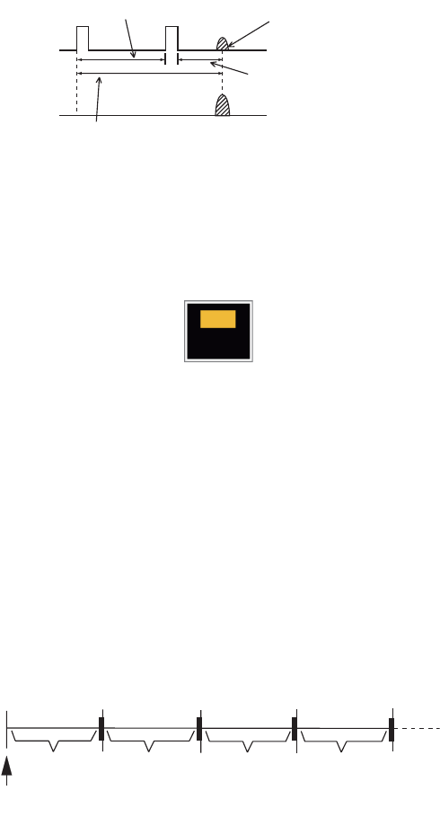
1. OPERATION
1-39
1.32 How to Reduce Second-trace Echoes
Echoes from very distant targets can appear as false echoes (second-trace echoes)
on the screen. The second-trace echo occurs when the return echo is received one
transmission cycle later, or after a next transmission of radar pulse.
Second-trace echoes
1. Press the MENU key to open the menu.
2. Use S or T to select [Echo] and press the ENTER key.
3. Use S or T to select [2nd Echo Rejector] and press the ENTER key.
2nd Echo Rejector options
4. Use S or T to select [Off] or [On] then press the ENTER key.
5. Press the MENU key to close the menu.
1.33 Watchman
The Watchman sounds the buzzer to tell the operator to check the radar display. The
radar transmits for one minute and then goes into standby for the selected time inter-
val. If the target alarm is active and a target is found in the alarm zone, Watchman is
cancelled, and the radar transmits continuously.
How watchman operates
In standby, the timer near the <WATCH> label at the center of the screen counts down
the remaining time until the transmission. When the set time interval has passed, the
audio alarm sounds, the timer disappears and the radar transmits for one minute. After
one minute, the audio alarm sounds, the radar stops transmitting and the watch alarm
timer again begins the countdown sequence.
If you press the STBY/TX key before the set time interval comes, the radar goes into
transmission.
Second-trace
echo
TX repetition
Actual range
False echo
range
Off
On
ST-BY
5,10 or 20 min.
Tx
1 min.
Watchman
starts
*
* Beep sounds just before radar transmits
or goes into standby.
ST-BY
Tx *
5,10 or 20 min.
1 min.
**
1. OPERATION
1-40
Do the following to activate the Watchman:
1. Press the MENU key to open the menu.
2. Use S or T to select [Alarm] and press the ENTER key.
3. Use S or T to select [Watchman] and press the ENTER key.
Watchman options
4. Use S or T to select [Off] or the time ([5min], [10min] or [20min]) then press the
ENTER key.
5. Press the MENU key to close the menu.
1.34 Color Selections
1.34.1 Preset colors
This radar is preset with color combinations that provide best viewing in day time, night
time and twilight. Below are the default color settings for each display item and display
color setting.
Display item, color design and color
1. Press the MENU key to open the menu.
2. Use S or T to select [Brill/Color] and press the ENTER key.
3. Use S or T to select [Display Color] and press the ENTER key.
Display Color options
4. Use S or T to select the color design and press the ENTER key.
5. Press the MENU key to close the menu.
Display Item Day Night Twilight Custom
Characters Black Red Green Green
Range rings, marks Green Red Green Green
Echo Yellow Green Green Yellow
Background White Black Blue Black
Off
5min
10min
20min
Day
Twilight
Custom
Night

1. OPERATION
1-41
1.34.2 Custom colors
The custom color design lets you select preferred echo, background, characters,
range rings and marks colors. Select [Custom] in the [Display Color] menu item (see
paragraph 1.34.1) to use the user selected echo, background, characters, range rings
and marks colors.
1. Press the MENU key to open the menu.
2. Use S or T to select [Brill/Color] and press the ENTER key.
3. Use S or T to select [Echo Color] and press the ENTER key.
Echo Color options
4. Use S or T to select an echo color and press the ENTER key. [Multi] displays
echoes in colors of red, yellow and green according to echo strength, and [Multi]
is not available in the [IEC] or [Russian-River] mode.
5. Use S or T to select [Background Color] and press the ENTER key.
Background Color options
6. Use S or T to select a background color and press the ENTER key.
7. Use S or T to select [Character Color] and press the ENTER key.
Character Color options
8. Use S or T to select a character color (including range rings and marks) and
press the ENTER key.
9. Press the MENU key to close the menu.
Yellow
Green
Orange
Multi
Black
DK Blue
Blue
White
Red
White
Green
1. OPERATION
1-42
1.35 Navigation Data
1.35.1 Navigation data during standby
The navigation data is shown in standby when [STBY Display] on the [Display] menu
is set to [Nav]. Appropriate sensors are required to display the data.
Navigation data display at standby
1.35.2 Navigation data at the bottom of the screen
The navigation data is displayed at the bottom of the screen.
Navigation data
Speed Standby indication
Depth Water temperature
Trip
Wind speed Wind direction
Time until TX
in watchman
Heading indicator
Heading
Course
Time to go to
destination waypoint
Bearing to
destination
waypoint Range to go to
destination waypoint
Waypoint mark Your ship position
Cross track error
(numeric value)
Cross track error
(graphic): For example,
when the indicator is off
to the right side, steer
your ship to the left to go
to the destination waypoint.
- Cursor latitude position
- Cursor longitude position
- Time to go to cursor position
Your ship position and speed - Bearing from your ship to waypoint
- Range from your ship to waypoint
- Time to go from your ship position to waypoint
LAT 34°56.123N
LON 135°34.567E
SPEED 12.3KN
LAT 34°56.123N
LON 135°34.567E
TTG 01:00
BRG
14.8°
RNG 0.876NM
TTG
00:20
OWN SHIP + CURSOR WAYPOINT

1. OPERATION
1-43
To show or hide the navigation data at the bottom of the screen, do the following:
1. Press the MENU key to open the menu.
2. Use S or T to select [Display] and press the ENTER key.
3. Use S or T to select [Data Box ] and press the ENTER key.
Data Box options
4. Use S or T to select an option and press the ENTER key.
[Off]: Turn off the data display.
[Nav]: Navigation data
[Target]: ARPA and AIS target data (See section 3.8 and section 4.5.)
[All]: Navigation data plus ARPA and AIS target data
5. Press the MENU key to close the menu.
1.36 Dynamic Range
You can change the dynamic range to erase unwanted weak echoes (sea reflections,
etc.). Select [Narrow], [Normal] or [Wide] depending on conditions.
1. Press the MENU key to open the menu.
2. Use S or T to select [Echo] and press the ENTER key.
3. Use S or T to select [Display-Dynamic] and press the ENTER key.
Display-Dynamic options
4. Use S or T to select [Narrow], [Normal] or [Wide] then press the ENTER key.
[Narrow]: Erase weak echoes.
[Normal]: Normal use
[Wide]: Display weaker echoes compared to [Narrow].
5. Press the MENU key to close the menu.
All
Off
Nav
Target
Narrow
Wide
Normal
1. OPERATION
1-44
1.37 Characteristics Curve
You can change the characteristics curve to reduce unwanted weak echoes (sea re-
flections, etc.). Select [1], [2] or [3] depending on conditions when unwanted weak
echoes hide wanted targets.
1. Press the MENU key to open the menu.
2. Use S or T to select [Echo] and press the ENTER key.
3. Use S or T to select [Display-Curve] and press the ENTER key.
Display-Curve options
4. Use S or T to select [1], [2] or [3] then press the ENTER key.
[1]: Reduce weak echoes.
[2]: Normal use
[3]: Display weaker echoes in stronger color compared to [1].
Display curve
5. Press the MENU key to close the menu.
321
Input level
Echo color
strength
Strong
Strong
1. OPERATION
1-45
1.38 Waypoint Marker
The waypoint marker shows the location of the destination waypoint set on a naviga-
tion plotter. The heading signal or course data are required. You can turn on/off the
waypoint marker as follows:
Waypoint marker
1. Press the MENU key to open the menu.
2. Use S or T to select [Others] and press the ENTER key.
3. Use S or T to select [WPT Mark] and press the ENTER key.
WPT Mark options
4. Use S or T to select [Off] or [On] then press the ENTER key.
5. Press the MENU key to close the menu.
1.39 Alarm Message
The alarm status window shows all current alarms.
Note: The alarm status window is not automatically displayed when an alarm occurs.
1. Press the MENU key to open the menu.
2. Use S or T to select [Alarm] and press the ENTER key.
+
Waypoint
marker
Off
On

1. OPERATION
1-46
3. Use S or T to select [Alarm Status] and press the ENTER key.
4. Press the CANCEL/HL OFF key to close the alarm status display.
5. Press the MENU key to close the menu.
Alarm category Meaning
SIGNAL MISSING*
"TRIGGER" Trigger signal lost (only for remote display)
"HEADING" Heading signal lost
"BEARING" Bearing signal lost
"GYRO" AD-10 format gyro signal lost
"VIDEO" Video signal lost
"POSITION" NMEA format position data lost
"NMEA_HDG" NMEA format heading signal lost
TARGET ALARM1(2)
"IN" An echo has entered a target alarm zone.
"OUT" An echo has exited a target alarm zone.
ARPA ALARM
"COLLISION" CPA and TCPA of an ARPA target are less than CPA and
TCPA alarm settings.
"LOST" The acquired ARPA target becomes lost.
"PROXIMITY" The range to an ARPA target is less than the user-set
proximity alarm range.
AIS ALARM
"COLLISION" CPA and TCPA of an AIS target are less than CPA and
TCPA alarm settings.
"PROXIMITY" The range to an AIS target is less than the user-set prox-
imity alarm range.
AIS SYSTEM*
"TX" TX stopped or TX error
"FAIL" System failure
"ANT" Antenna VSWR problem
"CH1" TDM2 RX1 board problem
"CH2" TDM2 RX2 board problem
"CH70" RX channel 70 problem
"MKD" Minimum input device lost
"EPFS" Navigator (GPS, etc.) problem
"L/L" Position data lost
"SOG" Speed data lost
Continued on following page
TRIGGER HEADING BEARING GYRO
VIDEO POSITION NMEA_HDG
IN OUT
IN OUT
COLLISION LOST PROXIMITY
COLLISION PROXIMITY
TX ANT CH1 CH2 CH70 FAIL MKD
EPFS L/L SOG COG HDG ROT
OVER_TEMP
[SIGNAL MISSING]
[TARGET ALARM1]
[TARGET ALARM2]
[ARPA ALARM]
[AIS ALARM]
[AIS SYSTEM]
[OTHER]
Alarm Status
[CANCEL/HL OFF]: Close
1. OPERATION
1-47
*: Have a qualified technician check the equipment.
1.40 Echo Area
You can select the display area from [Normal] or [Full Screen] to observe a wider over-
view of the surrounding area.
Echo area
1. Press the MENU key to open the menu.
2. Use S or T to select [Display] and press the ENTER key.
3. Use S or T to select [Echo Area] and press the ENTER key.
Echo Area options
4. Use S or T to select [Normal] or [Full Screen] then press the ENTER key.
5. Press the MENU key to close the menu.
Continued from previous page
"COG" Course data lost
"HDG" Heading data lost
"ROT" Rate of turn data lost
OTHER*
"OVER_TEMP" The temperature of the equipment is more than the spec-
ified value.
Alarm category Meaning
Normal Full Screen
Area in which echoes are displayed
Normal
Full Screen

1. OPERATION
1-48
1.41 Initial Sub Menu
The [Initial] sub menu in the [System] menu contains the items which allow you to ad-
just your radar to meet your needs.
1.41.1 How to open the Initial sub menu
1. Press the MENU key to open the menu.
2. Use S or T to select [Initial] and press the ENTER key.
Initial sub-menu
1.41.2 Description of Initial sub menu
[Key Beep]: When a key is pressed, a beep sounds. You can turn the beep on or off.
[Offcenter Speed]: Set the speed of your ship to calculate amount of your ship’s off-
center. The setting range is 1-99 (kn).
[Compass Type]: Select the type of bearing sensor connected to the radar; [True]
(gyrocompass, satellite compass) or [Magnetic] (magnetic compass).
[Range Preset]: You can select the radar ranges. Select a range and press the
ENTER key to switch on and off. See figure on following page for reference.
(Not available in Russian River or IEC modes.)
[Wind Direction]: The wind direction is shown as [Apparent] or [True].
[NMEA Port 1]: Set the baud rate of the equipment connected to Port 1 ([Auto],
[4800], or [38400] (bps)). [Auto] provides automatic detection of baud rate from [4800],
[9600], [19200] or [38400] (bps).
[NMEA Port 2]: Same function as Port 1 but for Port 2.
[NMEA Mixing Out]: Data input to Port 1 may be output from Port 2 mixed with data
output to Port 2. Select [On] to use this feature.
Note: At least two ranges must be turned on in the [Range Preset] menu. The maxi-
mum range available depends on the radar model.
0.0625 is not available in KM (kilometers). Available ranges are shown on the next
page.
Menu Initial
[ENTER]: Enter
[MENU]: Exit
[CANCEL/HL OFF]: Back
Others
Target
ARPA
AIS
GPS
System
Initial
Tests
Sector Blanks
Units
Key Beep
Offcenter Speed
Compass Type
Range Preset
NMEA Port 2
: Off
: 15kn
: True
: Off
: Apparent
NMEA Port 1 : Auto
Wind Direction
NMEA Mixing Out
: Auto
Turning on/off beep sounds
1. OPERATION
1-49
NM
(Nautical Miles)
KM
(Kilometers)
SM
(Statute Miles)
OffOff
On
On
On
On
On
On
On
On
On
On
On
On
On
Off
Off
Off
Off
Off
Off
Off
Off
Off
Exit? Yes Exit? Yes
On
On
On
On
On
On
On
On
On
On
On
On
On
Off
Off
Off
Off
Off
Off
Off
Off
Off
Off
Exit? Yes
On
Off
Off
Off
Off
Off
Off
Off
Off
Off
Off
On
On
On
On
On
On
On
On
On
On
On
On
Available ranges for FR-8065/FR-8125
NM
(Nautical Miles)
KM
(Kilometers)
SM
(Statute Miles)
Available ranges for FR-8255
Off
On
On
On
On
On
On
On
On
On
On
On
On
On
Off
Off
Off
Off
Off
Off
Off
Off
Exit? Yes
On
Off
Off
On
On
On
On
On
On
On
On
On
On
On
Off
Off
Off
Off
Off
Off
Off
Off
Exit? Yes
On
On
Off
On
On
On
On
On
On
On
On
On
On
On
On
Off
Off
Off
Off
Off
Off
Off
Off
Exit? Yes
On
On
Available ranges for FR-8045
NM
(Nautical Miles)
KM
(Kilometers)
SM
(Statute Miles)
On
On
On
On
On
On
On
On
On
On
Off
Off
Off
Off
Off
Off
Off
Off
Off
Off
Off
Off
Exit? Yes
On On
On
On
On
On
On
On
On
On
On
Off
Off
Off
Off
Off
Off
Off
Off
Off
Off
Off
Off
Exit? Yes
On
On
On
On
On
On
On
On
On
On
On
Off
Off
Off
Off
Off
Off
Off
Off
Off
Off
Off
Off
Exit? Yes
On

1. OPERATION
1-50
1.42 Units Sub Menu
You can select the unit of measurement for range, ship speed, depth, temperature and
wind speed on the [Units] sub menu in the [System] menu. You can not open this sub
menu in normal operation. To open this menu, select [Units], hold the CANCEL/HL
OFF key and press the MENU key five times.
Units sub menu
[Range Unit]: NM, KM, SM
When using IEC or Russian River mode, Range Unit can only be changed with the unit
in standby.
[Ship Speed Unit]: kn, km/h, mph
[Depth Unit]: m, ft, fa, pb, HR
[Temperature Unit]: °C, °F
[Wind Speed Unit]: kn, km/h, mph, m/s
Initial
Tests
Sector Blanks
Units
Factory
Installation
ARPA
AIS
GPS
Menu Units
System
Ship Speed Unit
Depth Unit
Temperature Unit
: kn
: ft
: °F
: kn
Wind Speed Unit
Range Unit : SM
[ENTER]: Enter
[MENU]: Exit
[CANCEL/HL OFF]: Back
Choosing a unit of range
1. OPERATION
1-51
1.43 Sector Blank
You must prevent the transmission in some areas to protect passengers and crew
from microwave radiation. Also, if the reflections of echoes from the mast appear on
the screen, you must prevent the transmission in that area. You can set two sectors.
1. Press the MENU key to open the menu.
2. Use S or T to select [Sector Blanks] and press the ENTER key.
3. Use S or T to select [Sect-Blank 1 (or 2) Status] and press the ENTER key.
Sector-Blank Status options
4. Use S or T to select [On] and press the ENTER key.
5. Use S or T to select [Sect-Blank 1 (or 2) Start] and press the ENTER key.
Sect-Blank Start setting window
6. Use S or T to set the start point of the sector and press the ENTER key.
7. Use S or T to select [Sect-Blank 1 (or 2) End] and press the ENTER key.
Sect-Blank End setting window
8. Use S or T to set the end point of the sector and press the ENTER key.
Note 1: You can not set the sector more than 180 degrees.
Note 2: You can not set the total width of sector 1 and sector 2 more than 270
degrees.
9. Press the MENU key to close the menu.
As shown in the following illustration, dashed lines mark the start and end points of the
sector.
Sector blank
Off
On
250°
(0°~359°)
+
Area of no
transmission
Start bearing
of sector
End bearing
of sector
1. OPERATION
1-52
1.44 Other Menu Items
1.44.1 Menu items on the [Brill/Color] menu
[Echo Shading]: You can adjust the color of the echo shade for better visibility. The
higher the setting, the darker the echo is displayed.
Echo Shading options
[Menu Transparency]: You can select the degree of transparency of the menu win-
dow so the menu window does not hide the echo display. [4] is the greatest degree of
transparency. [Off] functions to hide the echo display behind the menu window com-
pletely.
Note: Alpha blending technology is used for transparency effects.
Menu Transparency options
[Echo Color Mode]: You can select the color palette from [System] or [Custom]. [Sys-
tem] is the pre-set color palette and [Custom] is the color palette you can set yourself.
This function is not available in the [IEC] or [Russian-River] mode.
[Custom Echo Color]: You can adjust the echo color with the following two methods.
This function is not available in the [IEC] or [Russian-River] mode.
1
2
3
4
5
Off
1
2
3
4
Custom Echo Color
<System> <Custom>
Customizing echo colors
Rank
Red
Green
Blue
Fitting to Curve
Copy to Custom
Close this Window
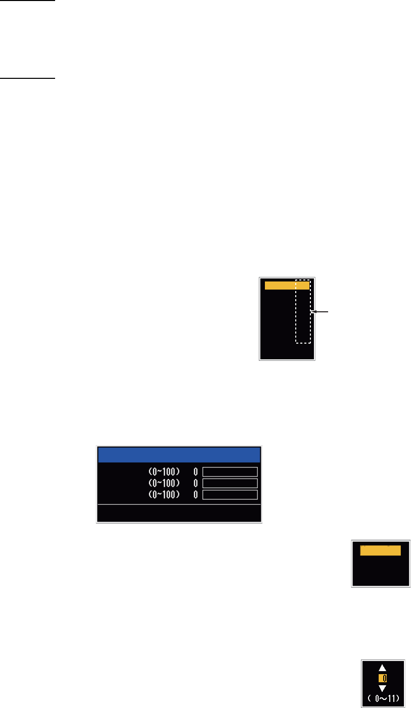
1. OPERATION
1-53
Method 1:
1. Select the echo rank to change on the [Rank] (setting range: 1 - 31).
2. Set the RGB values for selected echo rank on the [Red], [Green] and [Blue] (set-
ting range: 0 - 63).
Method 2:
1. Select 31 on the [Rank].
2. Set the RGB values for 31 echo rank on the [Red], [Green] and [Blue] (setting
range: 0 - 63).
3. Interpolate the RGB values between the maximum rank and minimum rank on the
[Fitting To Curve] with the following curves (setting range: -20 to 20).
Setting range > 0: Logarithmic curve, useful to emphasize the weak echoes.
Setting range = 0: Straight line
Setting range < 0: Exponential curve, useful to emphasize the strong echoes.
[Copy To Custom]: Copy the color palette from [System] to [Custom].
1.44.2 Menu items on the [Display] menu
[Base Text Display]: You can select on/off for the
text indications of the following items on the dis-
play. The settings on this function are used when
you set [Echo Area] to [Full Screen] on the [Dis-
play] menu. This function is not available in the
[IEC] or [Russian-River] mode.
The text indications set to off appear when you op-
erate any key. The indications disappear when there is no key operation for 10 sec-
onds.
[Gain/Sea/Rain Bar]: Open the Gain/Sea/Rain indicator. You can check the current
settings.
[STBY Display]: Set the function of the standby display.
[Normal]: Display "ST-BY" at the screen center.
[Nav]: Display navigation data.
[Economy]: Turn off the backlight of the LCD. The radar must be
switched from TX to ST-BY to activate this mode.
1.44.3 Menu items on the [Echo] menu
[Color Erase]: Erase the lower echo color whose level is set here. Set
a large value to display only the stronger echoes.
Range On
On
On
On
On
On
Mode
Alarm
Echo
EBL/VRM
+Cursor
EXIT? YES
Press the ENTER key
to change between
on and off.
Gain/Sea/Rain
GAIN MAN
SEA MAN
RAIN MAN
[CANCEL/HL OFF]: Close
Normal
Nav
Economy
1. OPERATION
1-54
1.45 Remote Display
You can use this radar as a remote display when you set [Input Source] to [Slave] on
the [Installation] sub menu. When this setting is done, the menu and display change
as described below. To display the radar image on the remote display, transmit from
the main radar.
Note: The message "Please turn to STBY-mode when you change this setting." ap-
pears when you switch the mode in transmission.
Unavailable menu items
The menu items not available with the remote display are shown in the table.
Display appearance
The display changes as shown in the following illustration.
Transmitting or standby display indications for remote display
Items unavailable with Function key F1, F2 and F3
• [Pulse Length] ([Echo] menu)
• [2nd-Echo Rejector] ([Echo] menu)
• [Watchman] ([Alarm] menu)
• [Tuning Mode] ([Tuning] menu)
Total TX time indication
The total TX time (TX TIME XXXXXX.XH) does not appear on the diagnostic test or
on the Normal standby display.
Menu Unavailable menu item(s)
[Echo] [Pulse Length], [2nd Echo Rejector]
[Custom 1, 2, 3] [Pulse Length]
[Alarm] [Watchman]
[Tuning] All menu items are not accessible.
[System] - [Sector Blanks] All menu items are not accessible.
[System] - [Installation] [Antenna Rotation], [MBS Adjust], [Auto Install Setup],
[Total TX Time]
HDG
OFFCENT(M)
Shown when display
unit functions as
remote display.
Tuning indicator
is not displayed.
Pulselength
is not displayed.
WTC is not displayed.
SLAVE
0.5
NM
0.125
CS1
H UP
TRAIL(T)
06MIN
ALM1_ACK
ALM2_OUT
359.9°

2-1
2. DESCRIPTION OF RADAR
2.1 General
2.1.1 Minimum and maximum ranges
Minimum range
The minimum range is defined by the shortest distance at which, using a scale of
0.0625 or 0.125 nm, a target that has an echoing area of 10 m2 is shown separate from
the point that shows the antenna position.
The minimum range depends on the pulselength, antenna height, and signal process-
ing (like main bang suppression and digital quantization). Use a shorter range scale
as far as it gives favorable definition or clarity of picture.
The FR-8045/FR-8065/FR-8125/FR-8255 radar series meets the requirements of
IEC 62252 5.14.1 (Class A).
Maximum range
The maximum detection range, Rmax, changes depending on the height of the anten-
na, the height of the target above the sea, the size, shape and material of the target,
and the atmospheric conditions.
Under normal atmospheric conditions, the maximum range is equal or a little shorter
than the optical horizon. The radar horizon is longer than the optical one by approxi-
mately 6%, because of the diffraction property of the radar signal. The Rmax is shown
in the following formula.
If the height of the antenna is 9 m and the height of the target is 16 m, the maximum
radar range is;
Note: The detection range is reduced by any precipitation (which absorbs the radar
signal).
R
max
= 2.2 x ( h1 + h2)
where R
max
: radar horizon (nautical miles)
h1: antenna height (m)
h2: target height (m)
Radar horizon
Optical horizon
Rmax = 2.2 x ( 9 + 16) = 2.2 x (3 + 4) = 15.4 nm
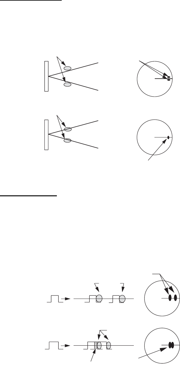
2. DESCRIPTION OF RADAR
2-2
2.1.2 Radar resolution
The bearing resolution and range resolution are important in radar resolution.
Bearing resolution
The bearing resolution is the ability of the radar to display the echoes received from
two targets at the same range as the separate echoes. The bearing resolution is pro-
portional to the antenna length and the wavelength.
Bearing resolution
Range resolution
The range resolution is the ability to display the echoes received from two targets on
the same bearing as separate echoes. The range resolution is calculated by only
pulselength.
The test targets used to calculate the range and bearing resolution are radar reflectors
that have an echoing area of 10 m2.
Range resolution
Targets
Targets
Horizontal beam width
Horizontal beam width
Separate
target
echoes
Overlapped
target echoes
Separate
target echoes
Overlapped
target echoes
Targets
Targets
Overlapping
Transmission
pulse
Transmission
pulse
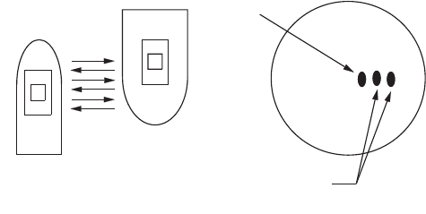
2. DESCRIPTION OF RADAR
2-3
2.1.3 Bearing accuracy
One of the most important features of the radar is how accurately the bearing of a tar-
get can be measured. The accuracy of bearing measurement depends on the narrow-
ness of the radar beam. The bearing taken is relative to the heading of the ship.
Correct adjustment of the heading line at installation is important to get accurate bear-
ings. To minimize the error when you measure the bearing of a target, put the target
echo at the extreme position on the screen by selecting a suitable range.
2.1.4 Range measurement
Measurement of the range to a target is important function of the radar. There are
three methods to measure range: the fixed range rings, the Variable Range Marker
(VRM), and the cursor (if the cursor is set to measure range and bearing). The fixed
range rings appear on the screen with a given interval and provide a rough estimate
of the range to a target. The diameter of VRM is increased or decreased so that the
marker touches the inner edge of the target (see paragraph 1.15.2). The VRM is a
more accurate range measurement than the fixed range rings. For cursor, see
section 1.13.
2.2 False Echoes
The echo signals can appear on the screen at positions where there is no target or
disappear when there are targets. These false echoes are shown below.
2.2.1 Multiple echoes
Multiple echoes occur when a transmitted pulse returns from a solid object like a large
ship, bridge, or breakwater. A second, a third or more echoes can be seen on the dis-
play at double, triple or other multiples of the actual range of the target as shown be-
low. You can reduce and remove the multiple reflection echoes with the A/C SEA
control.
Multiple echoes
Your ship
Target
True
echo
Multiple
echo
2. DESCRIPTION OF RADAR
2-4
2.2.2 Sidelobe echoes
When the radar pulse is transmitted, some radiation escapes on each side of the
beam, called "sidelobes”. If a target is where a target can be detected by the sidelobes
as well as the mainlobe, the side echoes can be shown on both sides of the true echo
at the same range. Sidelobes show normally only on short ranges and from strong tar-
gets. You can reduce the sidelobes with the A/C SEA control.
2.2.3 Virtual image
A large target close your ship can appear at two positions on the screen. One of them
is the true echo reflected by the target. The other is a false echo which is caused by
the mirror effect of a large object on or close your ship as shown in the following figure.
If your ship comes near a large metal bridge, for example, a false echo can temporarily
appear on the screen.
True target
Mainlobe (beam)
Antenna
Sidelobe
False echoes by sidelobes
Sidelobe
True
echo
False
echo
Your ship
Target ship
Mirror image
of target ship
Bridge
Route for direct reflection
Route for
indirect reflection
2. DESCRIPTION OF RADAR
2-5
2.2.4 Shadow sector
Funnels, stacks, masts, or derricks near the antenna interrupt the radar beam, and a
non-detecting sector can occur. Radar can not detect targets within this sector.
2.3 SART (Search and Rescue Transponder)
2.3.1 SART description
A Search and Rescue Transponder (SART) responds to any X-band (3 cm) radar with-
in a range of approximately 8 nm. Each radar pulse received causes the SART to
transmit a response which is swept continuously across the complete radar frequency
band.
Wharf and its echo
Large ship Size of blind sector depends
on size of obstruction and range.
Radar position Radar position
Wharf and its echo
Shadow sector occurs
because obstruction
(like mast) is in path
of radar beam.
Shadow sector
occurs because
wharf is hidden
behind ship.
Radar antenna
beamwidth
Screen A: When SART is distant Screen B: When SART is close
Echo from SART
Position of
SART
Your ship
position Your ship
position
SART mark
length
24 NM 1.5 NM
Position of
SART
Echo from
SART
Lines of 12 dots are displayed in
concentric arcs.

2. DESCRIPTION OF RADAR
2-6
2.3.2 General remarks on receiving SART
SART range errors
When the SART is at a range greater than approximately 1 nm, the first dot is dis-
played at 0.64 nm past the true position of the SART. When the range closes so that
the fast-sweep responses are also seen, the first range echoes are displayed at 150
m past the true position.
Range scale
When you find the SART position, do as follows:
1. Use the RANGE key to set the range scale to 6 nm or 12 nm.
2. Turn off [A/C Auto].
3. Turn off [Int Rejector].
SART display
To display only the SART echo clearly on the radar screen, reduce the tuning on man-
ual mode. The normal radar echoes get weak, but the SART echoes remain. Your ship
comes near the SART, the arc for the SART display becomes larger. Most of the radar
screen becomes fuzzy. Adjust the A/C SEA and GAIN controls to display the neces-
sary screen.
2.4 RACON
The RACON is a RAdar beaCON which sends radar-receivable signals in the radar
frequency spectrum (X- or S-band). There are several signal formats; in general, the
RACON signal appears on the radar screen as an echo in the shape of a rectangle
originating at a point just past the position of the radar beacon. It has a Morse coded
pattern. Note that the position on the radar display is not accurate.
Echoes on the radar screen Echo desription
Your ship position
Your ship position
RACON signal
RACON signal
RACON station
RACON station
3-1
3. ARPA OPERATION
The Automatic Radar Plotter ARP-11 (option) manually or automatically acquires and
tracks ten targets. When a target is acquired automatically or manually, a target is au-
tomatically tracked within 0.1 to 16 nm.
3.1 Precautions for Use
3.2 Controls for Use with ARPA
ENTER: Acquire the cursor-selected target. Display data for tracked target (in the data
box at the bottom of the screen).
CANCEL/HL OFF: Remove data of cursor-selected tracked target from the data box.
Stop tracking the cursor-selected target (when its data is not displayed in the data
box).
MENU: Access the [Target] and [ARPA] menus for ARPA operations.
CursorPad: Select a target to acquire (or cancel the tracking). Select a target to show
(or remove) target data.
Do not depend on one navigation device
for the navigation of the ship. The
navigator must check all aids available
to confirm position. Electronic aids are
not a replacement for basic navigation
principles and common sense.
· The ARPA automatically tracks an
automatically or manually acquired radar
target and calculates its course and
speed, indicating them by a vector. Since
the data from the auto plotter depend on
the selected radar targets, the radar must
be optimally tuned for use with the auto
plotter, to ensure required targets will not
be lost or unnecessary targets like sea
returns and noise will not be acquired
and tracked.
· A target is not always a landmass, reef,
ship, but can be returns from the sea
surface and clutter. As the level of clutter
changes with the environment, the
operator must correctly adjust the A/C
SEA, A/C RAIN and GAIN controls so
that the target echoes do not disappear
from the radar screen.
The tracking accuracy is affected by the
following:
· The tracking accuracy is affected by
course change. One to two minutes is
required to restore vectors to full
accuracy after a sudden course change.
(The actual amount depends on
gyrocompass specifications.)
· The amount of tracking delay is inversely
proportional to the relative speed of the
target. Delay is on the order of 15-30
seconds for high relative speed; 30-60
seconds for low relative speed.
The display accuracy is affected by the
following:
· Echo intensity
· Pulse width of radar transmission
· Radar bearing error
· Gyrocompass error
· Course change (your ship or target)
CAUTION
CAUTION
CAUTION
CAUTION

3. ARPA OPERATION
3-2
3.3 ARPA Display On/Off
You can turn the ARPA display on or off. The system continuously tracks ARPA tar-
gets regardless of this setting.
1. Press the MENU key to open the menu.
2. Use S or T to select [ARPA] and press the ENTER key.
3. Use S or T to select [Display] and press the ENTER key.
ARPA Display options
4. Use S or T to select [Off] or [On] then press the ENTER key.
5. Press the MENU key to close the menu.
3.4 How to Acquire and Track the Targets
Ten targets are acquired and tracked manually or automatically.
3.4.1 Manual acquisition
You can acquire a maximum of ten ARPA targets. When the automatic acquisition
([Auto Acquisition] on the [ARPA] menu) is set to on, you can manually acquire a max-
imum of five targets.
1. Use the CursorPad to put the cursor on the target to acquire.
2. Press the ENTER key.
The ARPA target symbol changes over time as shown below. A vector which indicates
the motion direction of the target appears approximately one minute after the acquisi-
tion.
ARPA target symbol
Target number
[River] and [Sea] (Non-IEC system): An acquired target gets the youngest unused
number. When a target is lost and disappears from the number list, the next acquired
target takes the number of that lost target (ie: In a five-target list, if the target 2 is lost,
the next acquired target takes the number of target 2).
[IEC] and [Russian-River] (IEC system): An acquired target gets the youngest un-
used number. When a target is lost and disappears from the number list, the next ac-
quired target takes the next sequential number until reaching a maximum 10. If the
target number reaches a maximum 10, the next acquired target takes the number of
a previously lost target.
Off
On
A
t acquisition 1 min. after
acquisition
3 min. after
acquisition
01 Target number
Vector
01
01
3. ARPA OPERATION
3-3
3.4.2 Automatic acquisition
When you set an automatic-acquisition area, the ARPA can acquire a maximum of five
targets automatically.
The automatic acquisition area is 2.0 to 2.5 nm in range and ±45° on either side of the
heading line in bearing. When you change the automatic acquisition to the manual ac-
quisition, targets tracked in automatic acquisition are continuously tracked.
Automatic acquisition area
1. Press the MENU key to open the menu.
2. Use S or T to select [ARPA] and press the ENTER key.
3. Use S or T to select [Auto Acquisition] and press the ENTER key.
Auto Acquisition options
4. Use S or T to select [On] and press the ENTER key.
5. Press the MENU key to close the menu.
3.5 How to Stop the Tracking of ARPA Target
When ten targets have been acquired, there is no more acquisition, unless targets are
cancelled. If you acquire additional targets, you must cancel one or more separate tar-
gets, or all targets. Use one of the following procedures.
3.5.1 How to stop the tracking of selected targets
1. Use the Cursorpad to put the cursor on the target to cancel the tracking.
2. Press the CANCEL/HL OFF key to cancel the tracking and erase the ARPA sym-
bol. The unit beeps twice and the symbol is erased from the screen.
3.5.2 How to stop the tracking of all targets
1. Press the MENU key to open the menu.
2. Use the CursorPad to put the cursor on the target to cancel the tracking.
3. Use S or T to select [ARPA] and press the ENTER key.
Automatic acquisition area
45° port 45° starboard
2.0 - 2.5 nm Heading line
Off
On
3. ARPA OPERATION
3-4
4. Use S or T to select [All Cancel] and press the ENTER key.
5. Use S to select [Yes] and press the ENTER key. All symbols
are erased from the screen and the long beep sounds.
6. Press the MENU key to close the menu.
3.6 Vector Attributes
3.6.1 What is a vector?
A vector is a line extending from a tracked target. A vector shows speed and course
of the target. The top of a vector shows estimated position of the target after the se-
lected vector time elapses. If you increase the vector length (time), you can evaluate
the risk of collision with any target.
When vector time is 15 minutes
3.6.2 Vector time and vector reference
1. Press the MENU key to open the menu.
2. Use S or T to select [Target] and press the ENTER key.
Target menu
Are your sure ?
Yes
No
Vector
Current position of the target
Vector time
Predicted position of the target in 15 minutes later
Custom 1
Custom 2
Target Trail
Custom 3
Alarm
Target
Tuning
ARPA
Others
AIS
GPS
Menu Target
Vector Reference
History Dots
History Interval
Proximity
: True
: 5
: 1min
: Off
TCPA : 1min
CPA
: Off
Vector Time : 6min
[ENTER]: Enter
[MENU]: Exit
[CANCEL/HL OFF]: Back
Adjusting a vector time to be displayed
3. ARPA OPERATION
3-5
3. UseS or T to select [Vector Time] and press the ENTER key.
Vector Time setting window
4. Use S or T to select time and press the ENTER key.
5. Use S or T to select [Vector Reference] and press the ENTER key.
Vector Reference options
6. Use S or T to select [Relative] or [True] then press the ENTER key. This function
is not activate for [IEC] or [Russian-River] purpose. The mode is set to [True].
[Relative]: Other ships’ vectors are displayed relative to your ship. This mode
helps find the targets on a collision course. If a ship is on a collision course with
your ship, the vector of a ship points toward your ship position.
[True]: Your ship’s and other ships’ vectors are displayed at their true motions.
This mode helps see the differences between moving and stationary targets.
7. Press the MENU key to close the menu.
Note: The functions of the [Target] menu are shared by ARPA and AIS.
3.6.3 Vector of your ship
The vector of your ship is shown as an arrow from your ship position. The vector of
your ship is shown on the following conditions:
• Connect ARP-11 (option)
• Select [True] on the menu item [Vector Reference] on the [Target] menu
• Independent of on/off on the menu item [Display] on the [ARPA] menu
Note: The vector of your ship is shown in the same color as the ARPA symbol color
(see section 3.12).
Example of vector display
6min
( 1min~30min)
Relative
True
+
Vector of
your ship
01
Data box
02
Cursor
03
04

3. ARPA OPERATION
3-6
3.7 History Display (target past position)
This radar can display time-spaced dots (maximum ten dots) that mark the past posi-
tions of any tracked ARPA target. You can evaluate actions of a target by the spaces
in between the dots. Below are examples of dot spacing and target movement.
Target movement and history display
You can select the number of history dots to display and the time interval to display
the history dots.
1. Press the MENU key to open the menu.
2. Use S or T to select [Target] and press the ENTER key.
3. Use S or T to select [History Dots] and press the ENTER key.
History Dots options
4. Use S or T to select number of history dots to display (5 or 10) or select [Off] to
turn off the history display.
5. Press the ENTER key.
6. Use S or T to select [History Interval] and press the ENTER key.
History Interval options
7. Use S or T to select the time interval and press the ENTER key.
8. Press the MENU key to close the menu.
(a) Ship turning (b) Ship running
straight (c) Ship reduced
speed
(d) Ship increased
speed
Off
10
5
15s
30s
2min
3min
6min
12min
1min
3. ARPA OPERATION
3-7
3.8 ARPA Target Data
You can show the data for a tracked ARPA target in the data box at the bottom of the
screen. To display ARPA target data, the menu item [Display] on the [ARPA] menu
must be set for [On] and the menu item [Data Box] on the [Display] menu must be set
for [Target] or [All].
1. Use the CursorPad to put the cursor on an ARPA target.
2. Press the ENTER key to show the data of the target.
ARPA target data
The symbol for the selected ARPA target is enlarged double to identify it from other
symbols.
To remove the data of a target from a data box, put the cursor on its target symbol and
press the CANCEL/HL OFF key.
Vector reference
Vector time
Target no.
Bearing, range, course,
speed,CPA, TCPA
+
ARPA target
selected for
data display
(B)01
Data box
Cursor
TRUE 06:00<ARPA> No. 02
A
BRG 78.4ºT RNG 2.032NM
SOG 0.49KNCRS 73.0º
TRUE 06:00<ARPA> No. 01
B
BRG 29.3ºT RNG 0.659NM
SOG 0.10KNCRS 12.3º
(A)02
3. ARPA OPERATION
3-8
3.9 CPA/TCPA Alarm
Set [CPA] (Closest Point of Approach) alarm range and [TCPA] (predicted Time to
CPA) alarm time to alert you to the targets that can be on a collision course. When
[CPA] and [TCPA] of any ARPA target become less than the preset [CPA] and [TCPA]
alarm settings, the audio alarm sounds. The alarm message "COLLISION" appears.
The target symbol changes to a dangerous target symbol (triangle) and its vector
flashes. You can stop the audio alarm with any key. The flashing of the triangle stops
when the tracked CPA and TCPA of an ARPA target is not in the [CPA] and [TCPA]
alarm setting. The ARPA continuously monitors [CPA] and [TCPA] of all tracked ARPA
targets.
Dangerous target symbol
This feature helps identify the targets that can be on a collision course. Correctly ad-
just GAIN, A/C SEA, A/C RAIN and other radar controls.
1. Press the MENU key to open the menu.
2. Use S or T to select [Target] and press the ENTER key.
3. Use S or T to select [CPA] and press the ENTER key.
4. Use S or T to select [CPA] distance and press the ENTER key.
5. Use S or T to select [TCPA] and press the ENTER key.
6. Use S or T to select TCPA and press the ENTER key.
7. Press the MENU key to close the menu.
CAUTION
CAUTION
Do not depend on the CPA/TCPA alarm
as the only method to detect the risk of
collision. The navigator is not released
of the responsibility to keep visual caution
for collision situations, whether or not the
radar or other plotting aid is in use.
Off
0.5NM
1NM
2NM
3NM
5NM
6NM 6min
30s
2min
3min
4min
5min
1min
12min
CPA distance settings TCPA settings
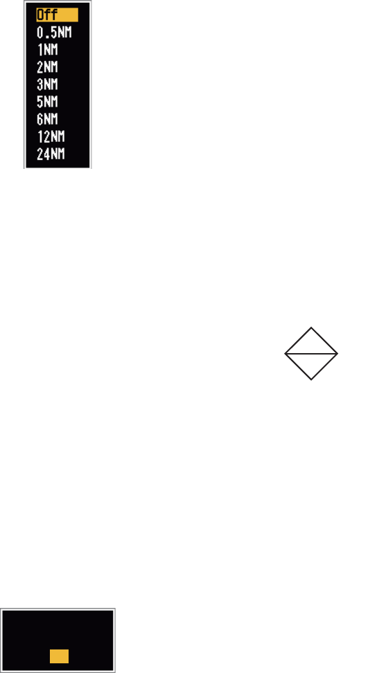
3. ARPA OPERATION
3-9
3.10 Proximity Alarm
The proximity alarm alerts you when an ARPA target is within the range you set. The
audio alarm sounds and the alarm message "PROXIMITY" appears. The target sym-
bol changes to a dangerous target symbol (triangle, see section 3.9) and flashes with
its vector. Press any key to stop the audio alarm. The flashing continues until the tar-
get is not within the range set, the alarm range is changed to exclude the target, or the
proximity alarm is deactivated.
1. Press the MENU key to open the menu.
2. Use S or T to select [Target] and press the ENTER key.
3. Use S or T to select [Proximity] and press the ENTER key.
Proximity settings
4. Use S or T to select the range and press the ENTER key.
5. Press the MENU key to close the menu.
3.11 Lost Target
When the system detects a lost target, the audio alarm sounds
and the alarm message "LOST" appears. The target symbol
becomes a flashing square like the illustration to the right.
When the system detects the target again, the target symbol
becomes a normal symbol.
To erase a lost target symbol, put the cursor on the symbol and press the CANCEL/
HL OFF key. If you leave a lost target symbol flashing, the symbol disappears after
one minute.
You can remove all lost ARPA targets from the screen as follows:
1. Press the MENU key to open the menu.
2. Use S or T to select [ARPA] and press the ENTER key.
3. Use S or T to select [ACK Lost Targets] and press the ENTER key.
ACK Lost Targets options
4. Use S to select [Yes] and press the ENTER key. All lost targets symbols are
erased from the screen and the long beep sounds.
5. Press the MENU key to close the menu.
Lost target symbol
Are you sure?
Yes
No

3. ARPA OPERATION
3-10
3.12 Symbol Color
You can select the ARPA symbol color from Green, Red, Blue, White or Black.
1. Press the MENU key to open the menu.
2. Use S or T to select [ARPA] and press the ENTER key.
3. Use S or T to select [Color] and press the ENTER key.
Color options
4. Use S or T to select the color and press the ENTER key.
5. Press the MENU key to close the menu.
Note: Symbols can not be shown in the same color as the background color.
Red
Blue
White
Black
Green

4-1
4. AIS OPERATION
Connected to the FURUNO AIS Transponders FA-150, FA-100, FA-50 or the AIS Re-
ceiver FA-30, the FR-8045/FR-8065/FR-8125/FR-8255 series can show the name,
position and other navigation data of the nearest 100 AIS transponder-equipped
ships.
This radar accepts heading and position data fixed by WGS-84 geodetic datum. Set
the datum to WGS-84 on the GPS navigator connected to this radar. If this radar is
connected with the FURUNO GPS Navigator GP-320B, see section 5.2 for the proce-
dure.
4.1 Controls for Use with AIS
ENTER: Activate the cursor-selected target. Display data for the selected active target
(in the data box at the bottom of the screen).
CANCEL/HL OFF: Remove data of cursor-selected AIS target from the data box.
Sleep the cursor-selected target (when its data is not displayed in the data box).
MENU: Access the [Target] and [AIS] menus for AIS operations.
CursorPad: Select a target to activate (or sleep). Select a target to show (or remove)
target data.
4.2 AIS Display On/Off
You can turn the AIS display on or off. The system continues processing AIS targets
regardless of on/off for AIS display when the AIS transponder is turned on.
1. Press the MENU key to open the menu.
2. Use S or T to select [AIS] and press the ENTER key.
AIS menu
Custom 1
Custom 2
Custom 3
Alarm
Target Trails
Tuning
Others
Target
ARPA
AIS
GPS
Color
Number of Targets
Sort By
Sector End
: Green
: 30
: Range
: 24.0NM
Sector Start : 340°
Range
Ignore Slow Targets
ACK Lost Targets
: 20°
: 5.0kn
Display : On
[ENTER]: Enter
[MENU]: Exit
[CANCEL/HL OFF]: Back
Turning on/off AIS display
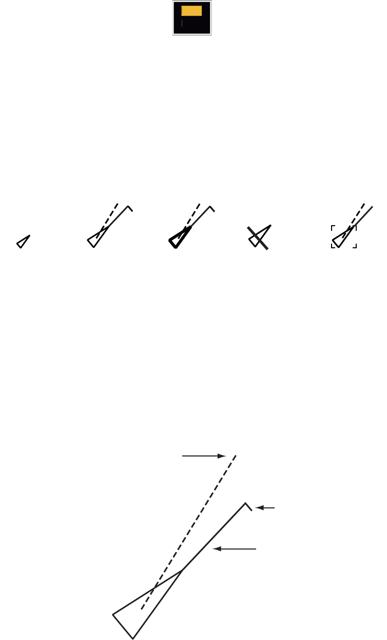
4. AIS OPERATION
4-2
3. Use S or T to select [Display] and press the ENTER key.
AIS-Display options
4. Use S or T to select [Off] or [On] then press the ENTER key.
5. Press the MENU key to close the menu.
4.3 AIS Symbols
When the AIS is turned on, AIS targets are displayed with AIS symbol as shown be-
low.
AIS symbols
Note: When the heading is changed on the head up mode, the AIS symbols are
erased, after the screen is changed, for a short time.
4.4 Activating, Sleeping Targets
When you change a sleeping target to an activated target, a vector shows the course
and speed of that target. You can easily judge the target movement by the vector.
Activated target
Off
On
Sleeping
target Activated
target
Dangerous
target
Lost target Target selected
for data display
Heading line
SOG (Speed Over Ground) and
COG (Course over Ground) vector
(If there is no heading data,
the line points in direction of COG.)
ROT
(Rate of Turn)
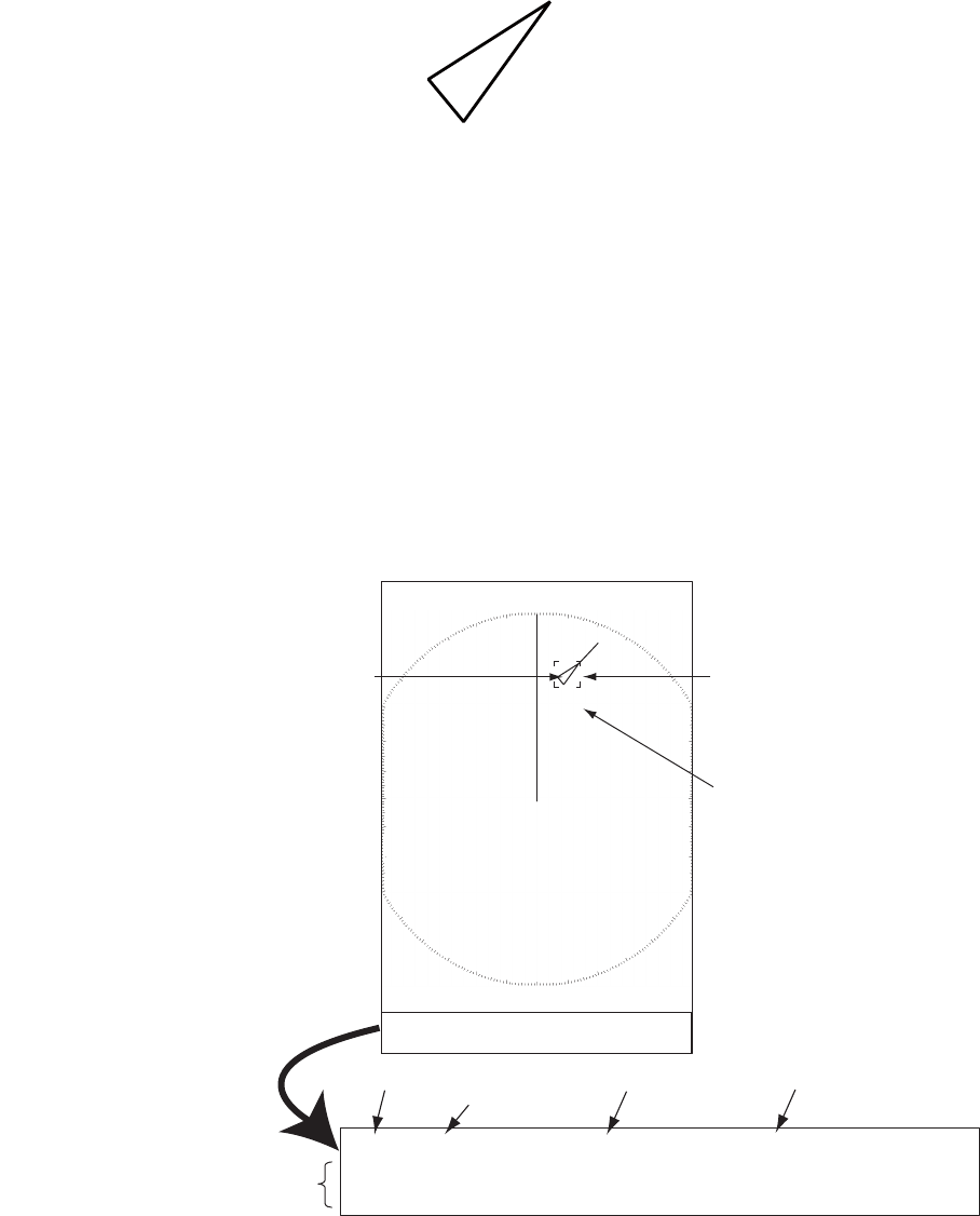
4. AIS OPERATION
4-3
When there are many activated targets on the screen, you can not easily identify the
activated targets from the radar images or ARPA targets. You can sleep an activated
target for easy view of radar images.
Sleeping target
To activate a target: Put the cursor on the target and press the ENTER key.
To sleep a target: Put the cursor on the target and press the CANCEL HL/OFF key.
4.5 AIS Target Data
You can show the AIS target data in the data box at the bottom of the screen. To dis-
play AIS target data, the menu item [Display] on the [AIS] menu must be set for [On]
and the menu item [Data Box] on the [Display] menu must be set for [Target] or [All].
1. Use the CursorPad to put the cursor on an activated target.
2. Press the ENTER key to show the data of the target.
To remove the target data from a data box, put the cursor on its target symbol and
press the CANCEL/HL OFF key.
AIS target
selected for
data display
MMSI of vessel Name of
vessel
PEGASUS
Cursor
Data box
TRUE 05:00 <AIS> MMSI: 123456789 NAME: PEGASUS
BRG
53.7°T
RNG 2.987NM COG
350.4°
SOG 23.45KN
CPA 1.65NM TCPA 06:14 LEN 100M BEAM 45M
Vector reference
Vector time
Bearing, range, course, speed
CPA, TCPA, length, beam of vessel
+
Name of vessel
(or MMSI)

4. AIS OPERATION
4-4
4.6 How to Sort Targets
You can sort the AIS targets received from the AIS transponder by range from your
ship, by sector, by CPA or TCPA.
1. Press the MENU key to open the menu.
2. Use S or T to select [AIS] and press the ENTER key.
3. Use S or T to select [Sort By] and press the ENTER key.
Sort By options
4. Use S or T to select sorting method and press the ENTER key.
[Range]: Sort targets within the display range set (see section 4.7), from nearest
to furthest.
[Sector]: Sort targets within the display sector set (see section 4.8) and within 24
nm, from nearest to furthest.
[CPA]: Sort targets within 24 nm by CPA, from closest to furthest.
[TCPA]: Sort targets within 24 nm by TCPA, from earliest time to latest time.
5. Press the MENU key to close the menu.
4.7 Display Range
You can set the AIS system to show only those AIS targets within the range you set.
The setting range is 0.1NM - 48.0NM for FR-8045, 0.1NM - 72.0NM for FR-8125/FR-
8065 and 0.1NM - 96.0NM for FR-8255. Actual range depends on the AIS Transpon-
der. If the target sorting method is selected to [Range], the target data within the range
set here are transmitted to this radar.
1. Press the MENU key to open the menu.
2. Use S or T to select [AIS] and press the ENTER key.
3. Use S or T to select [Range] and press the ENTER key.
AIS-Range setting window (for FR-8255)
4. Use S or T to set the display range and press the ENTER key.
5. Press the MENU key to close the menu.
Note: The unit of measurement for range is NM.
Range
Sector
CPA
TCPA
4. AIS OPERATION
4-5
4.8 How to Display the Targets within a Specific Sec-
tor
You can display AIS targets only within a specified sector. If the target sorting method
is selected to [Sector], the target data within the sector set here are transmitted to this
radar.
1. Press the MENU key to open the menu.
2. Use S or T to select [AIS] and press the ENTER key.
3. Use S or T to select [Sector Start] and press the ENTER key.
Sector Start setting window
4. Use S or T to set the start point for the sector and press the ENTER key.
5. Use S or T to select [Sector End] and press the ENTER key.
Sector End setting window
6. Use S or T to set the end point for the sector and press the ENTER key.
7. Press the MENU key to close the menu.
4.9 Number of Targets to Display
You can select the maximum number of AIS targets to display. The setting value is 10
to 100. When the screen becomes full of AIS targets, you can limit the number of AIS
targets to show. Targets are selected and displayed according to sort method. (See
section 4.6.)
1. Press the MENU key to open the menu.
2. Use S or T to select [AIS] and press the ENTER key.
3. Use S or T to select [Number of Targets] and press the ENTER key.
Number of Targets setting window
4. Use S or T to select the number of targets to display and press the ENTER key.
5. Press the MENU key to close the menu.

4. AIS OPERATION
4-6
4.10 Vector Attributes
4.10.1 What is a vector?
A vector is a line extending from a tracked target. A vector shows speed and course
of the target. The top of a vector shows estimated position of the target after the se-
lected vector time elapses. If you increase the vector length (time), you can evaluate
the risk of collision with any target.
4.10.2 Vector time and vector reference
1. Press the MENU key to open the menu.
2. Use S or T to select [Target] and press the ENTER key.
3. Use S or T to select [Vector Time] and press the ENTER key.
Vector Time setting window
4. Use S or T to select time and press the ENTER key.
5. Use S or T to select [Vector Reference] and press the ENTER key.
Vector Reference options
6. Use S or T to select [Relative] or [True] then press the ENTER key. This function
is not activate for [IEC] or [Russian-River] purpose. The mode is set to [True].
[Relative]: Other ships’ vectors are displayed relative to your ship. This mode
helps find targets on a collision course. If a ship is on a collision course with your
ship, the vector of a ship points toward your ship position.
[True]: Your ship’s and other ships’ vectors are displayed at their true motions.
This mode helps see the differences between moving and stationary targets.
7. Press the MENU key to close the menu.
6min
( 1min~30min)
True
Relative
4. AIS OPERATION
4-7
4.11 History Display (target past position)
This radar can display time-spaced dots (maximum ten dots) that marks the past po-
sitions of any tracked AIS target. You can evaluate actions of a target by the spaces
between the dots. Below are examples of dot spacing and target movement.
You can select the number of history dots to display and the time interval to display
the history dots.
1. Press the MENU key to open the menu.
2. Use S or T to select [Target] and press the ENTER key.
3. Use S or T to select [History Dots] and press the ENTER key.
History Dots options
4. Use S or T to select number of history dots to display (5 or 10) or select [Off] to
turn off the history display.
5. Press the ENTER key.
6. Use S or T to select [History Interval] and press the ENTER key.
History Interval options
7. Use S or T to select time interval and press the ENTER key.
8. Press the MENU key to close the menu.
(a) Ship turning (b) Ship running
straight
(c) Ship reduced
speed
(d) Ship increased
speed
Off
10
5
15s
30s
2min
3min
6min
12min
1min

4. AIS OPERATION
4-8
4.12 CPA/TCPA Alarm
Set CPA (Closest Point of Approach) alarm range and TCPA (predicted Time to CPA)
alarm time to alert you to targets that can be on a collision course. When CPA and
TCPA of any AIS target (including a sleeping target) become less than the preset CPA
and TCPA alarm settings, the audio alarm sounds. The alarm message "COLLISION"
appears. The target symbol changes to a dangerous target symbol (red) and its vector
flashes. You can stop the audio alarm and flashing with any key. The dangerous target
symbol is displayed until the AIS target is not in the CPA and TCPA alarm setting. The
AIS continuously monitors CPA and TCPA of all AIS targets.
This feature helps identify the targets that can be on a collision course.
1. Press the MENU key to open the menu.
2. Use S or T to select [Target] and press the ENTER key.
3. Use S or T to select [CPA] and press the ENTER key.
CPA options
4. Use S or T to select [CPA] distance and press the ENTER key.
5. Use S or T to select [TCPA] and press the ENTER key.
TCPA options
6. Use S or T to select [TCPA] and press the ENTER key.
7. Press the MENU key to close the menu.
0.5NM
1NM
2NM
3NM
6NM
5NM
Off
12min
6min
5min
4min
3min
2min
1min
30s

4. AIS OPERATION
4-9
4.13 Proximity Alarm
The proximity alarm alerts you when an AIS target is within the range you set. The au-
dio alarm sounds and the alarm message "PROXIMITY" appears. The target symbol
changes to a dangerous target symbol (red) and its vector flashes. Press any key to
stop the audio alarm and flashing. The dangerous target symbol is displayed until the
target is not within the range set, or the alarm range is changed to exclude the target,
or the proximity alarm is deactivated.
1. Press the MENU key to open the menu.
2. Use S or T to select [Target] and press the ENTER key.
3. Use S or T to select [Proximity] and press the ENTER key.
Proximity options
4. Use S or T to select the range and press the ENTER key.
5. Press the MENU key to close the menu.
4.14 Lost Target
When AIS data is not received from a target at fixed interval (3-5* report intervals), the
target symbol changes to the lost target symbol (flashing). No audio or visual alarm is
given for a lost target.
Lost target symbol
* The interval at which AIS data is sent depends on speed of the AIS transponder. For
detailed information, refer to the Operator's Manual for the AIS transponder.
You can remove all lost AIS targets from the display as follows:
1. Press the MENU key to open the menu.
2. Use S or T to select [AIS] and press the ENTER key.
3. Use S or T to select [ACK Lost Targets] and press the ENTER key.
ACK Lost Targets options
24NM
12NM
6NM
5NM
3NM
2NM
1NM
0.5NM
Off
Are you sure ?
Yes
No

4. AIS OPERATION
4-10
4. Use S to select [Yes] and press the ENTER key. All lost targets symbols are
erased from the screen and the long beep sounds.
5. Press the MENU key to close the menu.
4.15 Symbol Color
You can select the AIS symbol color from Green, Red (not available in the [IEC] or
[Russian-River] purpose), Blue, White or Black.
1. Press the MENU key to open the menu.
2. Use S or T to select [AIS] and press the ENTER key.
3. Use S or T to select [Color] and press the ENTER key.
Color options
4. Use S or T to select the color and press the ENTER key.
5. Press the MENU key to close the menu.
Note: Symbols can not be shown in the same color as the background color.
4.16 How to Ignore Slow Targets
You can prevent activation of the CPA/TCPA alarm against AIS targets that move at
a speed lower than set here. The AIS symbols are not affected by this setting.
1. Press the MENU key to open the menu.
2. Use S or T to select [AIS] and press the ENTER key.
3. Use S or T to select [Ignore Slow Targets] and press the ENTER key.
Ignore Slow Targets settings window
4. Use S or T to select speed (0.0 - 9.9 kn) and press the ENTER key.
5. Press the MENU key to close the menu.
Green
Red
Blue
White
Black

5-1
5. GPS OPERATION
If the FURUNO GPS Navigator GP-320B is connected to this radar, you can set GP-
320B from this radar.
5.1 Navigator Mode
1. Press the MENU key to open the menu.
2. Use S or T to select [GPS] and press the ENTER key.
3. Use S or T to select [Mode] and press the ENTER key.
Mode options
4. Use S or T to select [GPS] or [WAAS] then press the ENTER key.
5. Press the MENU key to close the menu.
5.2 Datum
Select the type of datum which matches the paper charts you use for navigation. Se-
lect [WGS-84] if the radar is connected to an AIS Transponder.
1. Press the MENU key to open the menu.
2. Use S or T to select [GPS] and press the ENTER key.
3. Use S or T to select [Datum] and press the ENTER key.
Datum options
4. Use S or T to select the type of datum and press the ENTER key. If you select
[WGS-84] or [Tokyo], go to step 7. If you select [Other], go to the next step.
5. Use S or T to select [Datum No] and press the ENTER key.
Datum No setting window
6. Use S or T to select the datum number and press the ENTER key. (The setting
range is 001 - 192 and 201 - 254. Refer to the page AP-5 “GEODETIC CHART
LIST”).
7. Press the MENU key to close the menu.
WAAS
GPS
WGS-84
Tokyo
Other
5. GPS OPERATION
5-2
5.3 WAAS Setup
Geostationary satellites, the type used with WAAS, provide more accurate position
data when compared to GPS. These satellites can be tracked automatically or manu-
ally. Auto tracking automatically searches for the best geostationary satellite from your
current position.
1. Press the MENU key to open the menu.
2. Use S or T to select [GPS] and press the ENTER key.
3. Use S or T to select [WAAS] and press the ENTER key.
WAAS options
4. Use S or T to select [AUTO] or [MANUAL] and press the ENTER key. If you se-
lect [Auto], go to step 7. If you select [Manual], go to the next step.
5. Use S or T to select [WAAS No] and press the ENTER key.
WAAS No setting window
6. Use S or T to select WAAS number and press the ENTER key.
(The setting range is 120 - 158. Refer to the following table.)
7. Press the MENU key to close the menu.
Provider Satellite type Longitude Satellite No
WAAS
Inmarsat-3-F4 (AOR-W) 142°W 122
Inmarsat-3-F3 (POR) 178°E 134
Intelsat Galaxy XV 133°W 135
TeleSat Anik F1R 107.3°W 138
EGNOS
Inmarsat-3-F2 (AOR-E) 15.5°W 120
Artemis 21.5°E 124
Inmarsat-3-F5 (IOR-W) 25°E 126
MSAS
MTSAT-1R 140°E 129
MTSAT-2 145°E 137
Manual
Auto
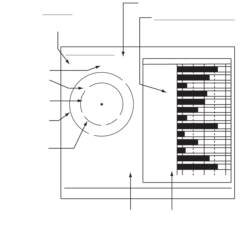
5. GPS OPERATION
5-3
5.4 Satellite Monitor
The Satellite Monitor provides the information about GPS and WAAS satellites. See
your GPS navigator's owner's manual for detailed information.
1. Press the MENU key to open the menu.
2. Use S or T to select [GPS] and press the ENTER key.
3. Use S or T to select [Satellite Monitor] and press the ENTER key.
Satellite monitor
4. Press the ENTER key to close only the satellite monitor display.
06
W3D DOP
1.5
15m
13
Altitude
01GPS
WAAS
12
24
16
SNRSatellite No.
30 40 50
122
01
31
18
19
06
07
09
08
13
North marker
DOP (Dilution of Precision, 0.0 - 99.0)
SNR of tracked GPS satellites
Satellites whose SNR is above
40 are used to fix position.
GPS mode
2D, 3D,
W2D, W3D
GPS satellite no.*
WAAS satellite
Satellites in ring
have elevation
angle of 5°
Satellites in ring
have elevation
angle of 45°
Altitude of
GPS antenna
from sea
surface
SNR of tracked
WAAS satellite
W
N
[MENU]: Close MENU [ENTER]: Close this window
* Satellites used to fix
position are shown in red.
Satellite Monitor
01
09
24
12
19
18
07
13
16
08
31

5. GPS OPERATION
5-4
5.5 Cold Start
Cold start, which clears the Almanac from the GPS receiver, can be necessary in the
following conditions:
• If you have turned off the power of the GPS receiver for a long time.
• The ship has moved far away from the previous fixing position (e.g., more than 500
km).
• Other reason that prevents the receiver from finding its position within five minutes
after you turn on the power.
To cold start, do the following:
1. Press the MENU key to open the menu.
2. Use S or T to select [GPS] and press the ENTER key.
3. Use S or T to select [Cold Start] and press the ENTER key.
Cold Start options
4. Use S or T to select [Yes] and press the ENTER key. After processing cold start,
the long beep sounds. (To stop cold start, press the CANCEL/HL OFF key instead
of the ENTER key.)
5. Press the MENU key to close the menu.
Are your sure ?
Yes
No
6-1
6. MAINTENANCE, TROUBLE-
SHOOTING
This chapter has information about maintenance and troubleshooting that the user
can follow to care for the equipment.
WARNING
ELECTRICAL SHOCK HAZARD
Do not open the equipment.
Only qualified personnel can work
inside the equipment.
Turn off the power before you
service the antenna unit. Post
a warning sign near the power
switch not to turn on the power
while you service the antenna
unit.
Prevent the potential risk of being
struck by the rotating antenna and
exposure to RF radiation hazard.
NOTICE
Do not apply paint, anti-corrosive sealant
or contact spray to plastic parts or
equipment coating.
These items contain products that can
damage plastic parts and equipment coating.

6. MAINTENANCE, TROUBLESHOOTING
6-2
6.1 Preventative Maintenance
Regular maintenance helps keep your equipment in good condition and prevents fu-
ture problems. Check the items shown in the table below to help keep your equipment
in good condition for years to come.
Maintenance
6.2 Fuse Replacement
A fuse is in the fuse holder on the power cable and inside the power supply unit, and
they protect the equipment from reverse polarity of the ship's mains and equipment
fault. If a fuse blows, find out the cause before replacing it. Use the correct fuse. Using
the wrong fuse will damage the equipment and void the warranty.
Interval Item Check Point Remedy
When necessary LCD Dust on the LCD Remove the dust from the
LCD with the tissue paper
and an LCD cleaner. To re-
move dirt or salt, use the
LCD cleaner. Change the
tissue paper often so as
not to damage the LCD.
3 to 6 months Ground terminal on dis-
play unit
Check for tight connec-
tions and corrosion
Tighten or replace as nec-
essary.
Display unit connectors Check for tight connec-
tion.
Tighten if the connectors
are loosened.
Exposed nuts and bolts
on the antenna unit.
Check for corroded or
loosened bolts.
Clean and repaint as nec-
essary. Use sealing com-
pound instead of paint.
Antenna radiator Check for dirt and
cracks on the radiator
surface.
Clean radiator surface with
a fresh-water-moistened
cloth. Do not use plastic
solvents to clean.
Unit Type Code No. Remarks
Display unit (fitted on power cable) FGBO 125V 10A PBF 000-155-826-10 24VDC
Power supply unit (for FR-8255) FGBO 125V 7A PBF 000-155-831-10 24VDC
WARNING
Use the proper fuse.
Use of a wrong fuse can result in damage
to the equipment and cause fire.

6. MAINTENANCE, TROUBLESHOOTING
6-3
6.3 Magnetron Life
When the life of the magnetron is reached, the targets do not appear on the display.
If long-range performance appears to have decreased, contact a FURUNO agent or
dealer about replacement of the magnetron. The magnetron changes with the type of
antenna unit.
6.4 LCD Backlight Life
The life of the LCD backlight, which provides the illumination for the LCD, is approxi-
mately 70,000 hours at 25°C (ambient temperature).
Model Magnetron Type Code No. Estimated life expectancy
FR-8045 E3571 000-146-867-12 App. 2,000 hours
FR-8065 MAF1422B 000-158-788-12 App. 3,000 hours
FR-8125 MAF1565N 000-174-559-11 App. 3,000 hours
FR-8255 M1458F 000-159-904-12 App. 2,000 hours

6. MAINTENANCE, TROUBLESHOOTING
6-4
6.5 Simple Troubleshooting
This section provides simple troubleshooting procedures which the user can follow to
restore normal operation. If you cannot restore normal operation, do not check inside
the unit. Have a qualified technician check the equipment.
Problem Remedy
You cannot turn on the power. • Check for blown fuse.
• Make sure that the power connector is
fastened.
• Check for corrosion on the power cable
connector.
• Check for damaged power cable.
• Check the battery for correct voltage
output.
There is no response when a key is
pressed.
Turn the power off, then on. If you do not
get a response, the key is damaged. Con-
tact your dealer for instructions.
The power is on and you operated the
STBY/TX key to transmit. The marks and
letters appear, but no echo appears.
Make sure that the antenna cable is fas-
tened.
Tuning is correctly adjusted, but sensitivity
is poor.
Replace the magnetron. Contact your
dealer.
The range is changed, but radar picture
does not change.
• Try to press the RANGE key again.
• Turn the display unit off then on.
Poor discrimination in range because of
too many echoes from the waves.
Adjust the A/C SEA control.
The true motion presentation is not work-
ing correctly.
• Make sure that the setting of [Display
Mode] in the [Display] menu is set to
[True Motion].
• Make sure that the heading and position
data are inputted and correct.
The range rings are not displayed. Make sure that the setting of [Rings Brill] in
the [Brill/Color] menu is not set to [Off].
Target is not tracked correctly because of
sea clutter.
Adjust A/C SEA and A/C RAIN controls.

6. MAINTENANCE, TROUBLESHOOTING
6-5
6.6 Advanced-level Troubleshooting
This section describes how to cure hardware and software troubles which only quali-
fied service persons must do.
Problem Possible cause or check
points Remedy
Power cannot be turned on. 1) Mains voltage/polarity
2) Power supply board
1) Correct the wiring and input
voltage.
2) Replace the power board.
Brilliance adjusted but no
picture.
1) SPU Board 1) Replace SPU Board.
Antenna not rotating. 1) Antenna drive mechanism 1) Replace the antenna drive
mechanism.
Data and marks not dis-
played in transmit.
1) SPU board 1) Replace SPU board.
Set GAIN to the maximum
with A/C SEA set at mini-
mum. Marks and indications
appear but no noise or echo.
1) Signal between antenna and
display unit
2) IF amplifier
3) Video amplifier board
1) Check continuity and isola-
tion of coaxial cable.
2) Replace IF amplifier.
3) Check coax line for fasten
connection. If the connection
is good, replace SPU board.
Marks, indications and noise
appear but no echo. (Trans-
mission leak show your ship
position is not present.)
1) Magnetron
2) Modulator board
3) SPU board
1) Check magnetron current.
2) Replace modulator board.
3) Replace the SPU board.
Picture not updated or pic-
ture freeze-up.
1) Bearing signal generator
2) SPU board
3) Video freeze-up
1) Make sure that the signal ca-
bles are fastened.
2) Replace the SPU board.
3) Turn the radar off, then on.
Radar is correctly tuned but
sensitivity is weak.
1) [2nd Echo Rejector] is [ON]
2) Dirt on radiator face
3) Deteriorated magnetron
4) Detuned MIC
1) Turn off the [2nd Echo Rejec-
tor] from the [Echo] menu.
2) Clean the radiator.
3) Check the magnetron current
with the radar transmitting on
48 nm range. If the current is
below normal, magnetron
may be defective. Replace
the magnetron.
4) Check the MIC detecting cur-
rent. If MIC detecting current
is below normal value, the
MIC may be detuned.
Range changed but picture
does not change.
1) RANGE key has defaults
2) SPU board
3) Video freeze-up
1) Try to operate the RANGE
key. If you can not operate
the RANGE key, replace the
keypad.
2) Replace the SPU board.
3) Turn the radar off, then on.
Range rings are not dis-
played.
1) Adjust their brilliance on the
[Brill/Color] menu.
2) SPU board
1) Replace the associated cir-
cuit board if unsuccessful.
2) Replace the SPU board.
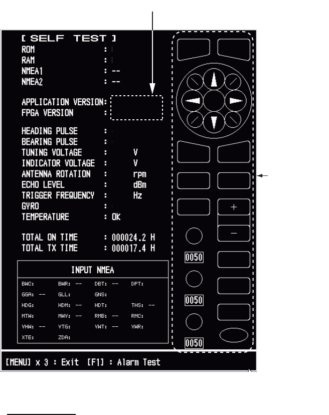
6. MAINTENANCE, TROUBLESHOOTING
6-6
6.7 Diagnostic Test
The diagnostic test checks the system for correct operation. This test is for use by ser-
vice technicians, but the user can do this test to provide the service technician with
information.
1. Press the MENU key to open the menu.
2. Use S or T to select [Tests] and press the ENTER key.
3. Use S or T to select [Self Test] and press the ENTER key.
Self Test screen
Test Results
• ROM, RAM: The results of the ROM and RAM test are displayed as "OK" or
"NG" (No Good).
• NMEA1, NMEA2: The results of the ports NMEA1 and NMEA2 are displayed as
"OK" or "- -". Ports NMEA1 and NMEA2 require a special connector to test
them. When a special connector is not connected, "- -" is shown. If "- -" is dis-
played with a special connector, contact your dealer for instruction.
• APPLICATION VERSION, FPGA VERSION: The program numbers and pro-
gram version numbers are displayed.
XX: Program version no.
OK
OK
OK
OK
10.1
4.2
48.1
-40
3112
123.4º
567
OK
OK
OK
OK
OK
OK
OK
OK
OK
OK
OK
OK
Key, buzzer,
knob control
and cursorpad
check
0359308-XX.XX
0359307-XX.XX

6. MAINTENANCE, TROUBLESHOOTING
6-7
• HEADING PULSE, BEARING PULSE: The results of the pulse input are dis-
played as "OK" or "NG". When [Antenna Rotation] is set to [Stop], or [Watch-
man] is set to [Off] in the STBY mode, this test is skipped and [- -] is shown for
both heading and bearing.
• TUNING VOLTAGE, INDICATOR VOLTAGE, ANTENNA ROTATION, ECHO
LEVEL, TRIGGER FREQUENCY: The results of measurement are displayed.
• GYRO: The current gyrocompass reading is displayed.
• TEMPERATURE: The result of the temperature test is displayed as "OK" or
"NG" and the temperature is measured and shown.
• TOTAL ON TIME, TOTAL TX TIME: The total number of hours, for which the
radar has been powered and has transmitted, are displayed.
• INPUT NMEA window: The condition of all the NMEA sentences being input to
this radar are displayed as "OK", or "- -". "- -" indicates no data input. Sentences
are updated every second.
Key check
Press each key one by one. A key’s on-screen location becomes green if the key
is normal.
Buzzer check
The F1 key tests on/off for the panel buzzer or external buzzer. To stop the buzz-
er, press the F1 key again.
Knob control check
Rotate each control knob. The four digits below the on-screen location for the
GAIN, A/C SEA and A/C RAIN knob controls show the control position. Press
each knob. The knob related on-screen circle changes in green if the knob is nor-
mal.
CursorPad check
Press each arrow and diagonal dot one by one. The on-screen location changes
in green if the key is normal.
4. Press the MENU key three times to leave the test.
5. Press the MENU key to close the menu.
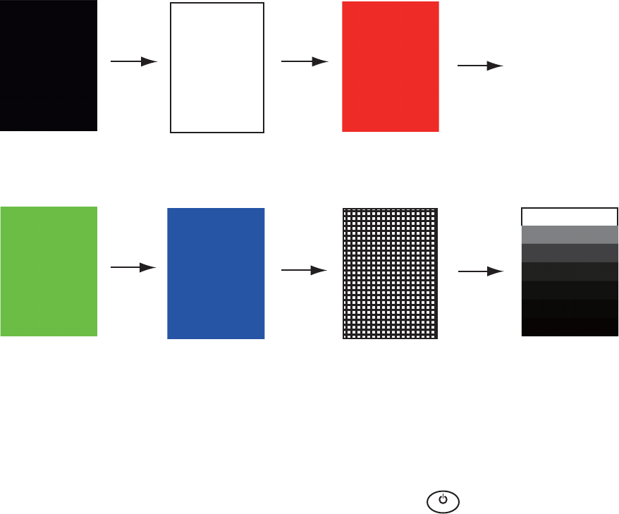
6. MAINTENANCE, TROUBLESHOOTING
6-8
6.8 LCD Test
1. Press the MENU key to open the menu.
2. Use S or T to select [Tests] and press the ENTER key.
3. Use S or T to select [LCD Pattern] and press the ENTER key.
4. Press the MENU key several times to close the menu.
Note 1: You can cancel the test at any time when you press the CANCEL/HL OFF
key.
Note 2: You can adjust the screen brilliance with the key during the test.
Black
MENU
key
MENU
key MENU
key
MENU
key MENU
key
MENU
key
White Red
Green Blue Checker board design 7 tones of gray
B
R
I
L
L

6. MAINTENANCE, TROUBLESHOOTING
6-9
6.9 ARPA Test
If the optional ARPA board is installed, its program number and test results ("OK" or
"NG") are shown on the screen. [ARPA Test] menu item does not operate when there
is no ARPA board. The radar must be transmitting to test the ARPA function.
1. Press the MENU key to open the menu.
2. Use S or T to select [Tests] and press the ENTER key.
3. Use S or T to select [ARPA Test] and press the ENTER key.
4. Press the MENU key three times to close the menu.
XXX: Program version no.
[ ARPA TEST ]
ROM : OK
RAM
: OK
ARPA VERSION
: 1859127XXX
SPEED : OK 12.3KN
COURSE
: OK 287.6
°
TRIGGER
: OK
VIDEO : OK
BEARING PULSE
: OK
HEADING PULSE : OK
MIN-HIT
: 0012
SCAN-TIME
: 0250
MANUAL-ACQ
: 03
AUTO-ACQ
: 05
FE-DATA1 : 0217
FE-DATA2 : 0023
ECHO NUMBER
[No. 1] 0123 [No. 2] 0321 [No. 3] 0084 [No. 4] 0234
[No. 5] 0110 [No. 6] 0219 [No. 7] 0073 [No. 8] 0145
[MENU] x 3 : Exit
6. MAINTENANCE, TROUBLESHOOTING
6-10
6.10 GPS Test
You can check the FURUNO GPS receiver GP-320B interfaced with this radar for cor-
rect operation as follows:
1. Press the MENU key to open the menu.
2. Use S or T to select [GPS] and press the ENTER key.
3. Use S or T to select [Self Test] and press the ENTER key. The program no. and
result of the test are shown, as "OK" or "NG" (No Good). When "NG" appears,
check the GPS receiver.
GPS Self Test screen
4. Press any key to close the test screen.
5. Press the MENU key to close the menu.
XX: Program version no. varies
according to equipment connected.
48502380XX
Self Test
Program No.
Result OK
AP-1
APPENDIX 1 MENU TREE
Main Menu
1
Brill/Color Default settings and values shown in bold italics
2
Display
3
Echo
4
Custom 1
5
Custom 2
6
Custom 3
7
Alarm
8
Target Trails
9
Tuning
10
Others
11
Target
12
ARPA
13
AIS
14
GPS
15 System
1 Brill\Color
Echo Brill (1 - 8)
Rings Brill (1 - 4)
Mark Brill (1 - 4)
HL Brill (1 - 4)
Character Brill (1 - 4)
Echo Shading (1 - 5) Default: 3
Display Color (Day, Night, Twilight, Custom )
Echo Color (Yellow , Green, Orange, Multi)
Background Color (Black , DK Blue, Blue, White)
Character Color (Green, Red, White) Default: Green
Menu Transparency(OFF, 1, 2, 3, 4)
Echo Color Mode (System , Custom)
Custom Echo Color
Rank (1 - 31)
Red (0 - 63)
Green (0 - 63)
Blue (0 - 63) Default = 35
Fitting to Curve (-20 - 20) Default=0
Copy to Custom (Yes, No )
2 Display
Display Mode (Head Up , Course Up, North Up, True Motion, True View)
Zoom (Off , On)
Zoom Mode (Relative , True, Target)
Offcenter Mode
Manual (Off , On)
Custom (Off , On)
Auto (Off , On)
EXIT (YES , NO)
Save Offcenter (Yes, No)
Echo Area (Normal , Full Screen)
Base Text Display
Range (Off , On)
Mode (Off , On)
Alarm (Off , On)
Echo (Off , On)
EBL/VRM (Off , On)
+Cursor (Off , On)
EXIT (YES , NO)
Data Box (Off , Nav, Target, All)
Gain/Sea/Rain Bar
GAIN (0 - 100)
SEA (0 - 100)
RAIN (0 - 100)
STBY Display (Normal , Nav, Economy)

APPENDIX 1 MENU TREE
AP-2
3Echo
Gain Mode (Auto , Manual)
Sea Mode (Auto , Manual)
Auto Sea (Coastal, Advanced )
Rain Mode (Auto , Manual)
Auto Rain (Calm, Moderate , Rough)
A/C Auto (Off , On)
Pulse Length (Short , Medium, Long)
Echo Stretch (Off, 1, 2, 3)
Echo Average (Off, 1, 2, Auto)
Noise Rejector (Off , On)
Wiper (Off , 1, 2)
Int Rejector (Off , 1, 2, 3)
Display-Dynamic (Narrow, Normal , Wide)
Display-Curve (1, 2, 3)
Color Erase (0 - 11)
2nd Echo Rejector (Off , On)
4Custom 1
Custom1 (Off, On )
Copy
Gain Mode (Auto , Manual)
Manual Gain (0 - 100) Default: 80
Sea Mode (Auto , Manual)
Auto Sea (Coastal, Advanced )
Manual Sea (0 - 100)
Rain Mode (Auto , Manual)
Auto Rain (Calm, Moderate , Rough)
Manual Rain (0 - 100)
A/C Auto (Off , On)
Pulse Length (Short , Medium, Long)
Echo Stretch (Off , On)
Echo Average (Off , On)
Noise Rejector (Off , On)
Wiper (Off , 1, 2)
Int Rejector (Off , 1, 2, 3)
Display-Dynamic (Narrow, Normal , Wide)
Display-Curve (1, 2, 3)
Color Erase (0 - 11)
5
Custom 2 (Same as Custom1)
6
Custom 3 (Same as Custom1)
7Alarm
Target Alarm 1 (In, Out)
Target Alarm 2 (In, Out)
Alarm Level (Low, Med, High)
Watchman (Off , 5min, 10min, 20min)
Panel Buzzer (Off, On )
External Buzzer (Off, On )
Alarm Status

APPENDIX 1 MENU TREE
AP-3
Time
15s (Off, On )
30s (Off, On )
1min (Off, On )
3min (Off, On )
6min (Off, On )
15min (Off, On )
30min (Off, On )
Continuous (Off , On)
EXIT (YES ,NO)
Gradation (Single, Multi)
Color (Green, Red, Blue , White, Black)
Mode (Relative, True )
Level (1, 2, 3)
Restart (Off, On )
Narrow (Off , On)
Own Ship (Off , 1, 2)
All Cancel (Yes, No )
9 Tuning
10 Others
11 Target
12 ARPA
13 AIS
8 Target Trails
Tuning Mode (Auto, Manual)
Manual Tuning (0.00V - 12.00V) Default 6.00V
Tuning Init Adjust (Yes, No )
F1 Setup
F2 Setup
F3 Setup
WPT Mark (On, Off )
EBL Reference (Relative , True)
VRM Unit (NM , KM, SM, KYD, NM&YD)
Cursor Position (Rng/Brg , Lat,Lon)
TLL Key Mode (TLL Output, Origin Mark, Both)
Vector Time (1min - 30min) Default=6min
Vector Reference (Relative, True )
History Dots (Off, 5, 10)
History Interval (15s, 30s, 1min , 2min, 3min, 6min, 12min)
CPA (Off , 0.5NM, 1NM, 2NM, 3 NM, 5NM, 6NM)
TCPA (30s, 1min , 2min, 3min, 4min, 5min, 6min, 12min)
Proximity (Off , 0.5NM, 1NM, 2NM, 3NM, 5NM, 6NM, 12NM, 24NM)
Display (Off , On)
Color (Green , Red, Blue, White, Black)
Auto Acquisition (Off , On)
ACK Lost Targets (Yes, No )
All Cancel (Yes, No )
Display (Off , On)
Color (Green , Red, Blue, White, Black)
Number of Targets (10 - 100) Default=30
Sort by (Range , Sector, CPA, TCPA)
Range (0.1NM - 72.0NM*) Default: 24.0 NM
Sector Start (0º - 359º) Default: 340°
Sector End (0º - 359º) Default: 20°
Ignore Slow Targets (0.0 - 9.9kn) Default=5.0kn
ACK Lost Targets (Yes, No )
*: FR-8255 - (0.1NM - 96.0NM)
FR-8045 - (0.1NM - 48.0NM)

APPENDIX 1 MENU TREE
AP-4
14 GPS
Mode (GPS, WAAS)
Datum (WGS-84, Tokyo, Other)
Datum No. (001 - 192, 201 - 254)
WAAS (Auto, Manual)
WAAS No. (120 - 158)
Sattelite Monitor
Self Test
Cold Start (Yes, No )
15 System
Initial
Key Beep (Off , On)
Offcenter Speed (1kn - 99kn) Default=15kn
Compass Type (Magnetic, True )
Range Preset
Wind Direction (Apparent, True )
NMEA Port 1 (Auto, 4800bps, 38400bps)
NMEA Port 2 (Auto, 4800bps, 38400bps)
NMEA Mixing Out (Off , On)
Tes ts
Self Test
LCD Pattern
ARPA Test
Sector Blanks
Sect-Blank 1 Status (Off , On)
Sect-Blank 1 Start (0º - 359º)
Sect-Blank 1 End (0º - 359º)
Sect-Blank 2 Status (Off , On)
Sect-Blank 2 Start (0º - 359º)
Sect-Blank 2 End (0º - 359º)
Units
Range Unit (NM , KM, SM)
Ship Speed Unit (kn, km/h, mph)
Depth Unit (m, ft, fa, pb, HR)
Temperature Unit (ºC, ºF )
Wind Speed Unit (kn, km/h, mph, m/s)
Installation (For use by the installer. Not accessible by the user)
Factory (For use by the installer. Not accessible by the user)

AP-5
APPENDIX 2 GEODETIC CHART LIST
001: WGS84
002: WGS72
003: TOKYO :
004: NORTH AMERICAN 1927 : Mean Value (CONUS)
005: EUROPEAN 1950 : Mean Value
006:
AUSTRALIAN GEODETIC 1984
: Australia & Tasmania
007: ADINDAN-MN : Mean Value (Ethiopia & Sudan)
008: ADINDAN-E : Ethiopia
009: ADINDAN-MA : Mali
010: ADINDAN-SE : Senegal
011: ADINDAN-SU : Sudan
012: AFG : Somalia
013: AIN EL ABD 1970 : Bahrain Is.
014: ANNA 1 ASTRO 1965 : Cocos Is.
015: ARC 1950-MN : Mean Value
016: ARC 1950-B : Botswana
017: ARC 1950-L : Lesotho
018: ARC 1950-M : Malawi
019: ARC 1950-S : Swaziland
020: ARC 1950-ZR : Zaire
021: ARC 1950-ZM : Zambia
022: ARC 1950-ZB : Zimbabwe
023: ARC 1960-MN : Mean Value (Kenya & Tanzania)
024: ARC 1960-K : Kenya
025: ARC 1960-T : Tanzania
026: ASCENSION IS. 1958 : Ascension Is.
027: ASTRO BEACON “E” : Iwo Jima Is.
028: ASTRO B4 SOR. ATOLL : Tern Is.
029: ASTRO POS 71/4 : St. Helena Is.
030:
ASTRONOMIC STATION 1952
: Marcus Is.
031:
AUSTRALIAN GEODETIC 1966
: Australia & Tasmania
032: BELLEVUE (IGN) : Efate & Erromango Is.
033: BERMUDA 1957 : Bermuda Is.
034: BOGOTA OBSERVATORY : Columbia
035: CAMPO INCHAUSPE : Argentina
036: CANTON IS. 1966 : Phoenix Is.
037: CAPE : South Africa
038: CAPE CANAVERAL :
039: CARTHAGE : Tunisia
040: CHATHAM 1971 : Chatham Is. (New Zealand)
041: CHUA ASTRO : Paraguay
042: CORREGO ALEGRE : Brazil
043: DJAKARTA (BATAVIA) : Sumatra Is. (Indonesia)
044: DOS 1968 : Gizo Is. (New Georgia Is.)
045: EASTER IS. 1967 : Easter Is.
046: EUROPEAN 1950-WE : Western Europe
047: EUROPEAN 1950-CY : Cyprus
048: EUROPEAN 1950-EG : Egypt
049: EUROPEAN 1950-ESC :
050: EUROPEAN 1950-EIS :
051: EUROPEAN 1950-GR : Greece
052 EUROPEAN 1950-IR : Iran
053: EUROPEAN 1950-SA : Italy, Sardinia
054: EUROPEAN 1950-SI : Italy, Sicily
055: EUROPEAN 1950-NF : Norway & Finland
056: EUROPEAN 1950-PS : Portugal & Spain
057: EUROPEAN 1979 : Mean Value
058: GANDAJIKA BASE : Republic of Maldives
059: GEODETIC DATUM 1949 : New Zealand
060: GUAM 1963 : Guam Is.
061: GUX 1 ASTRO : Guadalcanal Is.
062: HJORSEY 1955 : Iceland
063: HONG KONG 1963 : Hong Kong
064: INDIAN-TV : Thailand & Vietnam
065: INDIAN-BIN : Bangladesh, India & Nepal
066: IRELAND 1965 : Ireland
067: ISTS 073 ASTRO 1969 : Diego Garcia
068: JOHNSTON IS. 1961 : Johnston Is.
069: KANDAWALA : Sri Lanka
070: KERGUELEN IS. : Kerguelen Is.
071: KERTAU 1948 : West Malaysia & Singapore
072: LA REUNION : Mascarene Is.
073: L. C. 5 ASTRO : Cayman Brac Is.
074: LIBERIA 1964 : Liberia
075: LUZON : Philippines (excl. Mindanao Is.)
076: LUZON-M : Mindanao Is.
077: MAHE 1971 : Mahe Is.
078: MARCO ASTRO : Salvage Islands
079: MASSAWA : Eritrea (Ethiopia)
080: MERCHICH : Morocco
081: MIDWAY ASTRO 1961 : Midway Is.
082: MINNA : Nigeria
083: NAHRWAN-O : Masirah Is. (Oman)
084: NAHRWAN-UAE : United Arab Emirates
085: NAHRWAN-SA : Saudi Arabia
086: NAMIBIA : Namibia
087: MAPARIMA, BWI : Trinidad & Tobago
088:
NORTH AMERICAN 1927WU
: Western United States
089:
NORTH AMERICAN 1927EU
: Eastern United States
090:
NORTH AMERICAN 192
7AK : Alaska
091:
NORTH AMERICAN 1927BH
:Bahamas (excl. San Salvador Is.)
Mean Value (Japan, Korea & Okinawa)
Mean Value (Florida & Bahama Is.)
England, Scotland, Channel & Shetland Is.
England, Ireland, Scotland & Shetland Is.
092: NORTH AMERICAN 1927SS : Bahamas, San Salvador Is.
093: NORTH AMERICAN 1927CN : Canada (incl. Newfoundland Is.)
094: NORTH AMERICAN 1927AB : Alberta & British Columbia
095: NORTH AMERICAN 1927EC : East Canada
096: NORTH AMERICAN 1927MO : Manitoba & Ontario
097: NORTH AMERICAN 1927NE :
098: NORTH AMERICAN 1927YK : Yukon
099: NORTH AMERICAN 1927CZ : Canal Zone
100: NORTH AMERICAN 1927CR : Caribbean
101: NORTH AMERICAN 1927CA : Central America
102: NORTH AMERICAN 1927CU : Cuba
103: NORTH AMERICAN 1927GR : Greenland
104: NORTH AMERICAN 1927MX : Mexico
105: NORTH AMERICAN 1983AK : Alaska
106: NORTH AMERICAN 1983CN : Canada
107: NORTH AMERICAN 1983CS : CONUS
108: NORTH AMERICAN 1983MX : Mexico, Central America
109: OBSERVATORIO 1966 : Corvo & Flores Is. (Azores)
110: OLD EGYPTIAN 1930 : Egypt
111: OLD HAWAIIAN-MN : Mean Value
112: OLD HAWAIIAN-HW : Hawaii
113: OLD HAWAIIAN-KA : Kauai
114: OLD HAWAIIAN-MA : Maui
115: OLD HAWAIIAN-OA : Oahu
116: OMAN : Oman
117:
ORDNANCE SURVEY OF GREAT BRITAIN 1936-NM
: Mean Value
118:
ORDNANCE SURVEY OF GREAT BRITAIN 1936-E
: England
119:
ORDNANCE SURVEY OF GREAT BRITAIN 1936-IM
: England, Isle
of Man & Wales
120:
ORDNANCE SURVEY OF GREAT BRITAIN 1936-SSI
: Scotland &
Shetland Is.
121:
ORDNANCE SURVEY OF GREAT BRITAIN 1936-WL
: Wales
122: PICO DE LAS NIVIES : Canary Is.
123: PITCAIRN ASTRO 1967 : Pitcairn Is.
124: PROVISIONS SOUTH CHILEAN 1963: South Chile (near 53°S)
125: PROVISIONAL SOUTH AMERICAN 1956MN: Mean Value
126: PROVISIONAL SOUTH AMERICAN 1956BO: Bolivia
127: PROVISIONAL SOUTH AMERICAN 1956NC: Chile-Northern Chile
(near 19°S)
128: PROVISIONAL SOUTH AMERICAN 1956SC: Chile-Southern Chile
(near 43°S)
129: PROVISIONAL SOUTH AMERICAN 1956CO: Columbia
130: PROVISIONAL SOUTH AMERICAN 1956EC: Ecuador
131: PROVISIONAL SOUTH AMERICAN 1956GY: Guyana
132: PROVISIONAL SOUTH AMERICAN 1956PR: Peru
133: PROVISIONAL SOUTH AMERICAN 1956VN: Venezuela
134: PUERTO RICO : Puerto Rico & Virgin Is.
135: QATAR NATIONAL : Qatar
136: QORNOQ : South Greenland
137: ROME 1940 : Sardinia Is.
138: SANTA BRAZ :
139: SANTO (DOS) : Espirito Santo Is.
140: SAPPER HILL 1943 : East Falkland Is.
141: SOUTH AMERICAN 1969MN : Mean Value
142: SOUTH AMERICAN 1969AG : Argentina
143: SOUTH AMERICAN 1969BO : Bolivia
144: SOUTH AMERICAN 1969BR : Brazil
145: SOUTH AMERICAN 1969CH : Chile
146: SOUTH AMERICAN 1969CO : Columbia
147: SOUTH AMERICAN 1969EC : Ecuador
148: SOUTH AMERICAN 1969GY : Guyana
149: SOUTH AMERICAN 1969PA : Paraguay
150: SOUTH AMERICAN 1969PR : Peru
151: SOUTH AMERICAN 1969TT : Trinidad & Tobago
152: SOUTH AMERICAN 1969VZ : Venezuela
153: SOUTH ASIA : Singapore
154: SOUTHEAST BASE : Porto Santo & Madeira Is.
155: SOUTHWEST BASE :
156: TIMBALAI 1948 :
157: TOKYO JP : Japan
158: TOKYO KP : Korea
159: TOKYO OK : Okinawa
160: TRISTAN ASTRO 1968 : Tristan da Cunha
161: VITI LEVU 1916 : Viti Levu Is. (Fiji Is.)
162: WAKE-ENIWETOK 1960 : Marshall Is.
163: ZANDERIJ : Surinam
164: BUKIT RIMPAH :
165: CAMP AREA ASTRO : Camp Mcmurdo Area, Antarctica
166: G. SEGARA : Kalimantan Is. (Indonesia)
167: HERAT NORTH : Afghanistan
168: HU-TZU-SHAN : Taiwan
169: TANANARIVE OBSERVATORY 1925 : Madagascar
170: YACARE : Uruguay
171: RT-90 : Sweden
172: TOKYO :
Mean Value (Japan, Korea & Okinawa)
173: AIN EL ABD 1970 : Bahrain Is.
Northwest Territories & Saskatchewan
Sao Miguel, Santa Maria Is. (Azores)
Faial, Graciosa, Pico, Sao Jorge & Terceria Is.
Brunei & East Malaysia (Sarawak & Sabah)
Bangka & Belitung Is. (Indonesia)
174:
175: ARC 1960
ARS-A : Mean Value (Kenya, Tanzania)
: Kenya

APPENDIX 2 GEODETIC CHART LIST
AP-6
178: CAPE CANAVERAL
179: EASTER IS. 1967
180: EUROPEAN 1950 :
181: JHONSTON IS. 1961 : Jhonston Is.
182: NAHRWAN : Saudi Arabia
183:
NAPARIMA, BWI
: Trinidad & Tobago
184: NORTH AMERICAN 1927 : Caribbeen
185: OLD HAWAIIAN : Oahu
186: SAPPER HILL 1943 : East Falkland Is.
187: TIMBALAI 1948 :
Brunei & East Malaysia (Sarawak & Sabah)
188: TOKYO : Japan
189: TOKYO : South Korea
190: TOKYO : Okinawa
191: WAKE-ENIWETOK 1960 : Marshall Is.
192: HU-TZU-SHAN : Taiwan
201: ADINDAN : Burkina Faso
202: ADINDAN : Cameroon
203: ARC 1950 : Burundi
204: AYABELLE LIGHTHOUSE : Djibouti
205: BISSAU : Guinea-Bissau
206: DABOLA : Guinea
207: EUROPEAN 1950 : Tunisia
208: LEIGON : Ghana
209: MINNA : Cameroon
210: M’ PORALOKO : Gebon
211: NORTH SAHARA 1959 : Algeria
212 POINT58 :
Mean Solution (Burkina Faso & Niger)
213: POINTE NOIRE 1948 : Congo
214: SIERRA LEONE 1960 : Sierra Leone
215:
VOIROL 1960
: Algeria
216:
AIN EL ABD 1970
: Saudi Arabia
217: INDIAN : Bangladesh
218: INDIAN : India & Nepal
219: INDIAN 1954 : Thailand
220: INDIAN 1960 : Vietnam (near 16N)
221: INDIAN 1960 :
Con Son Is. (Vietnam)
222: INDIAN 1975 : Thailand
223: INDONESIAN 1974 :
224:
CO-ORDINATE SYSTEM 1937 OF ESTONIA
: Estonia
225: EUROPEAN 1950 : Malta
Portugal & Spain
Indonesia
226: EUROPEAN 1950 : Tunisia
227: S-42 (PULKOVO 1942) : Hungary
228: S-42 (PULKOVO 1942) : Poland
229: S-42 (PULKOVO 1942) : Czechoslovakia
230: S-42 (PULKOVO 1942) : Latvia
231: S-42 (PULKOVO 1942) :
232: S-42 (PULKOVO 1942) : Albania
233: S-42 (PULKOVO 1942) : Romenia
234: S-JTSK : Czechoslovakia
235: NORTH AMERICAN 1927 : East of 180W
236: NORTH AMERICAN 1927 : West of 180W
237: NORTH AMERICAN 1983 : Aleutian Is.
238: NORTH AMERICAN 1983 : Hawaii
239: SOUTH AMERICAN 1969 : Baltra, Galapagos Is.
240: ANTIGUA IS. ASTRO 1943 : Antigua, Leeward Is.
241: DECEPTION IS. : Deception Is., Antarctica
242: FORT THOMAS 1955 : Nevis, St. Kitts, Leeward Is.
243: ISTS 061 ASTRO 1968 : South Georgia Is.
244:
MONTSERRAT IS. ASTRO 1958
: Montserrat, Leeward Is.
245: FEUNION : Mascarene Is.
246: AMERICAN SAMOA 1962 : American Samoa Is.
247: INDONESIAN 1974 : Indonesia
248: KUSAIE ASTRO 1951 :
Caroline Is., Fed. States of Micronesia
249: WAKE Is. ASTRO 1952 : Wake Atoll
250: EUROPEAN 1950 :
Iraq, Israel, Jordan, Kuwait, Lebanon,
251:
HERMANNSKOGEL : Yugoslavia (Prior to 1990) Slovenia,
252:
INDIAN
: Pakistan
253: PULKOVO 1942 : Russia
254: VOIROL 1874 : Tunisia/Algeria
Kazakhstan
:Easter Is.
:Mean Value (Florida & Bahama Is.)
Saudi Arabia, and Syria
Croatia Bonsia and Herzegovina Serbia
176:
177: ARS-B
ASCENSION IS. 1958
: Tanzania
: Ascension Is.
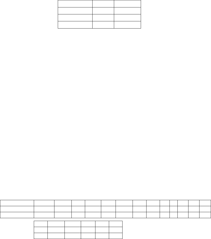
FURUNO
FR-8045/8065/8125/8255
SP - 1 E3632S01D-M
SPECIFICATIONS OF MARINE RADAR
FR-8045/8065/8125/8255
1 GENERAL
1.1 Range, Pulse length (PL) and Pulse repetition rate (PRR)
Range (NM) PL (μs) PRR (Hz)
0.0625 to 1.6 0.08 2100
1.5 to 3.2 0.3 1200
3 to 96 0.8 800
1.2 Maximum range 48 NM (FR-8045), 72 NM (FR-8065/8125), 96 NM (FR-8255)
1.3 Range resolution 15 m (FR-8045), 20 m (FR-8065/8125/8255)
1.4 Bearing resolution 1.9° (XN-12A), 1.2° (XN-13A)
1.5 Minimum range 18 m (FR-8045), 25 m (FR-8065/8125/8255)
1.6 Bearing accuracy Within ±1.0°
1.7 Range ring accuracy 0.9 % of range or 8 m, which is the greater
2 ANTENNA UNIT
2.1 Radiator Slotted wave-guide array
2.2 Polarization Horizontal
2.3 Rotation speed 24 rpm (RSB-0070), 48 rpm (RSB-0073)
2.4 Radiator length 120 cm (XN-12A), 180 cm (XN-13A)
2.5 Horizontal beamwidth 1.9° (XN-12A), 1.35° (XN-13A)
2.6 Vertical beamwidth 22°
2.7 Sidelobe
XN-12A -24 dB or less (within ±10% of main-lobe)
-30 dB or less (outside ±10% of main-lobe)
XN-13A -28 dB or less (within ±10% of main-lobe)
-35 dB or less (outside ±10% of main-lobe)
3 TRANSCEIVER MODULE
3.1 Frequency and modulation 9410 MHz ±30MHz (X-band), P0N
3.2 Peak output (nominal) FR-8045: 4 kW, FR-8065: 6 kW, FR-8125: 12 kW, FR-8255: 25 kW
3.3 Range scale, Ring interval (RI) and Number of rings
Range (NM) 0.125 0.25 0.5 0.75 1 1.5 2 3 4 6 8 12 16
RI (NM) 0.025 0.05 0.1 0.25 0.2 0.25 0.5 0.5 1 1 2 3 4
Rings 5 5 5 3 5 6 4 6 4 6 4 4 4
24 36 48 64 72 96
6 6 8 16 12 16
4 6 6 4 6 6
3.4 Modulation FET switching method
3.5 IF amplifier 60 MHz
3.6 Tuning Automatic or manual
3.7 Warm-up time 90 s approx. (FR-8045/8065/8125), 180 s approx. (FR-8255)
4 DISPLAY UNIT
4.1 Indication system 12.1 inch TFT color LCD,800 x 600 dots (SVGA)
4.2 Radar indication pixel 300 dots in radius
4.3 Effective radar diameter 184 mm
4.4 Marks Heading line, Bearing scale, Range ring, Tuning indicator, Cursor,
FURUNO
FR-8045/8065/8125/8255
SP - 2 E3632S01D-M
North mark, Variable range marker (VRM), Electric Bearing Line
(EBL), Target alarm zone, Zoom window, Waypoint mark,
Origin mark
4.5 Alphanumeric indication Range, Range ring interval, Pulse length, Display mode, Off-center,
Heading data*, Target trail, Tuning indicator, Target alarm,
Echo stretch (ES), Echo average (EAV), EBL, Vector time*,
Range and bearing to cursor or cursor position*,
Interference rejecter (IR), Auto anti-clutter (A/C auto), VRM,
Navigation data* (position, speed, course), ARPA/ATA/AIS data*
*: external data required
4.6 Audio alarm volume 74 dB (A)
5 INTERFACE
5.1 Number of port
Serial 2 ports: IEC61162-1/2 (NMEA0183 V1.5/2.0/3.0/4.0)
Heading sensor 1 port: AD-10 or NMEA format
USB 1 port: USB2.0 for maintenance
Contact closure 1 port for buzzer, 12 mA max.
Video output 1 port for sub monitor
5.2 I/O sentences
Input BWC, BWR, DBT, DPT, GGA, GLL, GNS, HDG, HDM, HDT, MTW,
MWV, RMB, RMC, THS,TTM (for radiotelephone only), VHW, VTG,
VWR, VWT, XTE, ZDA
Output RSD, TLL, TTM (ARP-11 required)
5.3 Output proprietary sentence pidat
6 POWER SUPPLY
FR-8045 24 VDC: 3.7 A (48 rpm only)
FR-8065 24 VDC: 3.6 A (24 rpm), 3.9 A (48 rpm)
FR-8125 24 VDC: 3.9 A (24 rpm), 4.5 A (48 rpm)
FR-8255 Display unit: 24 VDC: 3.0 A
Power supply unit: 24 VDC: 2.3 A (24 rpm), 2.7 A (48 rpm)
7 ENVIRONMENTAL CONDITIONS
7.1 Ambient temperature
Antenna unit -25°C to +55°C
Display/power supply unit -15°C to +55°C
7.2 Relative humidity 93% or less at +40°C
7.3 Degree of protection
Antenna unit IP26
Display unit IP25 (panel), IP22 (chassis)
Power supply unit IP20
7.4 Vibration IEC 60945 Ed.4
8 UNIT COLOR
8.1 Antenna unit N9.5
8.2 Display unit N2.5
8.3 Power supply unit N2.5

IN-1
INDEX
A
A/C RAIN key .......................................... 1-12
A/C SEA control ...................................... 1-11
A/C SEA key ............................ 1-28, 2-3, 2-4
Adjust sensitivity...................................... 1-10
Advanced troubleshooting......................... 6-5
AIS operation ............................................ 4-1
activate/sleep a target ............................. 4-2
controls.................................................... 4-1
CPA/TCPA alarm .................................... 4-8
display on/off ........................................... 4-1
display range........................................... 4-4
display targets in specific sectors............ 4-5
history display ......................................... 4-7
lost target ................................................ 4-9
number of targets displayed.................... 4-5
proximity alarm........................................ 4-9
slow target ignore.................................. 4-10
symbol colors ........................................ 4-10
symbols ................................................... 4-2
target data ............................................... 4-3
target sorting ........................................... 4-4
vector attributes....................................... 4-6
vector time and reference ....................... 4-6
Alarm message ....................................... 1-45
meanings............................................... 1-46
ARPA operation ........................................ 3-1
acquire and track target .......................... 3-2
automatic acquisition of target ................ 3-3
controls.................................................... 3-1
CPA/TCPA alarm .................................... 3-8
display on/off ........................................... 3-2
history display ......................................... 3-6
lost target ................................................ 3-9
manual acquisition of target .................... 3-2
proximity alarm........................................ 3-9
stop tracking............................................ 3-3
symbol colors ........................................ 3-10
target data ............................................... 3-7
target number.......................................... 3-2
target symbols......................................... 3-2
vector attributes....................................... 3-4
vector of your ship................................... 3-5
vector time and reference ....................... 3-4
ARPA test.................................................. 6-9
Auto adjust clutter ................................... 1-13
B
Brill/color menu items.............................. 1-52
C
CANCEL/HL OFF key ............................. 1-34
Characteristics curve............................... 1-44
Color selection ........................................ 1-40
custom................................................... 1-41
presets .................................................. 1-40
Controls
overview .................................................. 1-1
Course-up mode ....................................... 1-8
Cursor ..................................................... 1-14
data ....................................................... 1-14
CUSTOM key .................................1-20, 1-34
Custom setup .......................................... 1-34
description of items ............................... 1-35
how to setup.......................................... 1-36
D
Diagnostic test........................................... 6-6
Display brilliance ....................................... 1-4
Display indications .................................... 1-3
Display menu items................................. 1-53
Display mode
course-up mode ...................................... 1-8
head-up mode ......................................... 1-8
north-up mode......................................... 1-8
relative motion......................................... 1-7
selection .................................................. 1-7
true motion .............................................. 1-7
true motion mode .................................... 1-9
true view mode........................................ 1-9
Dynamic range ........................................ 1-43
E
EBL
measure range to target with EBL......... 1-18
EBL key................................................... 1-18
EBL reference ......................................... 1-19
Echo area................................................ 1-47
Echo average .......................................... 1-28
Echo menu items .................................... 1-53
Echo stretch ............................................ 1-28
F
Function keys .......................................... 1-37
available options ................................... 1-37
changing function key program ............. 1-37
F1 key ................................................... 1-37
F2 key ................................................... 1-37
F3 key ................................................... 1-37
G
Gain
manual mode ........................................ 1-10
Gain adjustment ...................................... 1-10
GAIN key................................................. 1-10
GPS operation........................................... 5-1
cold start.................................................. 5-4
datum ...................................................... 5-1
navigator mode ....................................... 5-1
satellite monitor ....................................... 5-3
WAAS setup............................................ 5-2
INDEX
IN-2
GPS test...................................................6-10
H
Heading line
how to hide temporarily ..........................1-34
Head-up mode ...........................................1-8
How to measure the range and bearing between
two targets ...............................................1-19
I
Initial sub-menu........................................1-48
description of menu items ......................1-48
how to open............................................1-48
Interference rejector.................................1-15
L
LCD backlight life .......................................6-3
LCD test .....................................................6-8
M
Magnetron life ............................................6-3
MENU key..................................................1-4
Menu overview...........................................1-4
N
Navigation data
screen bottom ........................................1-42
standby...................................................1-42
Noise rejector...........................................1-38
North-up mode ...........................................1-8
O
OFF CENTER key ................1-19, 1-24, 1-25
Off center the display
automatic shift formula...........................1-25
Off-center the display...............................1-24
auto mode ..............................................1-25
custom mode..........................................1-25
manual mode .........................................1-24
mode selection.......................................1-24
Origin mark ..............................................1-33
P
Panel dimmer.............................................1-4
Power on/off...............................................1-2
Power/BRILL key ............................... 1-2, 1-4
Presentation brilliance..............................1-34
Preventative maintenance .........................6-2
Pulselength selection ...............................1-20
Q
Quick start..................................................1-2
R
RACON ......................................................2-6
Radar .........................................................2-1
bearing accuracy......................................2-3
false echoes.............................................2-3
minimum and maximum ranges...............2-1
multiple echoes ........................................2-3
range measurement.................................2-3
resolution..................................................2-2
shadow sector..........................................2-5
sidelobe echoes .......................................2-4
virtual image.............................................2-4
Rain clutter adjustment ............................1-12
auto mode ..............................................1-12
manual mode .........................................1-13
RANGE key...................................... 1-10, 2-6
Range scale selection..............................1-10
Range to a target .....................................1-16
fixed range rings.....................................1-16
VRM .......................................................1-17
Remote display ........................................1-54
appearance ............................................1-54
unavailable functions..............................1-54
unavailable items ...................................1-54
S
SART .........................................................2-5
display ......................................................2-6
range errors..............................................2-6
range scale...............................................2-6
Sea clutter adjustment
auto mode ..............................................1-11
manual mode .........................................1-11
Second-trace echo reduction ...................1-39
Sector blank .............................................1-51
Simple troubleshooting...............................6-4
Start-up screen ..........................................1-2
STBY/TX key ................................... 1-2, 1-39
System configuration.................................... xi
T
Target alarm.............................................1-21
alarm level options .................................1-23
buzzer on/off ..........................................1-23
deactivate...............................................1-23
selecting type .........................................1-22
setting a zone.........................................1-21
stopping audio........................................1-22
temporary sleep .....................................1-23
TARGET ALARM key..................... 1-21, 1-23
Target position .........................................1-33
Target trails ..............................................1-29
color .......................................................1-31
gradation ................................................1-31
narrow trails............................................1-33
own ship trail ..........................................1-33
relative mode..........................................1-30
restart/stop .............................................1-32
start/stop ................................................1-30
trail level.................................................1-32
trail time..................................................1-29
true mode...............................................1-30
TLL key ....................................................1-33
modes ....................................................1-33
TRAILS key..............................................1-30
True motion mode......................................1-9
True view mode..........................................1-9
Tuning ........................................................1-6
INDEX
IN-3
U
Units sub-menu ....................................... 1-50
V
VRM key.................................................. 1-17
W
Watchman ............................................... 1-39
Waypoint marker ..................................... 1-45
Wiper....................................................... 1-38
Z
Zoom ....................................................... 1-26
mode selection ...................................... 1-26
relative mode......................................... 1-26
target mode ........................................... 1-27
true mode .............................................. 1-26