Furuno Gp32 Users Manual
GP32 to the manual 6ea9ccb0-771c-49d7-90ec-4b380f9caf94
2015-02-02
: Furuno Furuno-Gp32-Users-Manual-428716 furuno-gp32-users-manual-428716 furuno pdf
Open the PDF directly: View PDF ![]() .
.
Page Count: 88
- SAFETY INSTRUCTIONS
- TABLE OF CONTENTS
- FOREWORD
- SYSTEM CONFIGURATION
- WHAT IS WAAS?
- EQUIPMENT LISTS
- 1. OPERATIONAL OVERVIEW
- 2. PLOTTER DISPLAY OVERVIEW
- 3. WAYPOINTS (MARKS)
- 4. ROUTES
- 5. DESTINATION
- 6. ALARMS
- 7. OTHER FUNCTIONS
- 7.1 Calculating Range, Bearing, TTG and ETA
- 7.2 WAAS Setup
- 7.3 DGPS setup
- 7.4 Bearing Reference
- 7.5 Magnetic Variation
- 7.6 Geodetic Chart System
- 7.7 Units of Measurement
- 7.8 Position Display Format
- 7.9 Time Difference (using local time), Time Format
- 7.10 GPS Setup
- 7.11 User Display Setup
- 7.12 Resetting Trip and Odometer Distances
- 7.13 Uploading, Downloading Waypoint, Route Data
- 7.14 Language
- 8. MAINTENANCE & TROUBLESHOOTING
- 9. INSTALLATION
- APPENDIX
- SPECIFICATIONS
- OUTLINE DRAWINGS
- INTERCONNECTION DIAGRAMS
- INDEX
- Declaration of Conformity
Back

The paper used in this manual
is elemental chlorine free.
・FURUNO Authorized Distributor/Dealer
9-52 Ashihara-cho,
Nishinomiya, 662-8580, JAPAN
Telephone : +81-(0)798-65-2111
Fax :
+81-(0)798-65-4200
A
:
MAY
2002
Printed in Japan
All rights reserved.
E4
:
NOV
.
06, 2008
Pub. No.
OME-44200-E4
*00080928811**00080928811*
(
TATA
)
GP-32/37
*
00080928811
*
*
00080928811
*
* 0 0 0 8 0 9 2 8 8 1 1 *
i
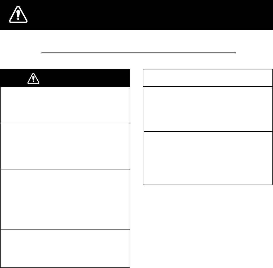
SAFETY INSTRUCTIONS
WARNING
Do not open the equipment.
Only qualified personnel should work inside
the equipment.
Do not disassemble or modify the
equipment.
Fire, electrical shock or serious injury can
result.
Immediately turn off the power at the
switchboard if the equipment is emitting
smoke or fire.
Continued use of the equipment can cause
fire or electrical shock. Contact a FURUNO
agent for service.
Use the proper fuse.
Use of a wrong fuse can damage the
equipment or cause fire.
NOTICE
Be sure the power supply is compatible
with the equipment.
Incorrect power supply may cause the
equipment to overheat.
The useable temperature range for the
antenna unit is -25°C to 70°C;
-15°C to 55°C for the display unit.
Use of the equipment out of those ranges
may damage the equipment.
Safety Instructions for the Operator
ii
Safety Instructions for the Installer
WARNING
Do not open the cover unless totally
familiar with electrical circuits and
service manual.
Improper handling can result in electrical
shock.
Turn off the power at the switchboard
before beginning the installation.
Fire or electrical shock can result if the
power is left on.
Be sure that the power supply is
compatible with the voltage rating of
the equipment.
Connection of an incorrect power supply
can cause fire or equipment damage. The
voltage rating of the equipment appears
on the label above the power connector.
Use the proper fuse.
Use of a wrong fuse can damage the
equipment or cause fire.
NOTICE
Observe the following compass safe
distances to prevent interference to a
magnetic compass:
Display
unit
Standard Steering
compass compass
0.80 m 0.55 m

iii
TABLE OF CONTENTS
FOREWORD ................................... v
SYSTEM CONFIGURATION.......... vi
WHAT IS WAAS?.......................... vii
EQUIPMENT LISTS ..................... viii
1. OPERATIONAL OVERVIEW......1
1.1 Controls ...................................... 1
1.2 Turning On and Off Power .......... 2
1.3 Adjusting Brilliance and Contrast 2
1.4 Display Modes ............................ 3
1.5 Menu Overview........................... 7
1.6 Simulation Display ...................... 8
2. PLOTTER DISPLAY OVERVIEW9
2.1 Choosing the Display Range....... 9
2.2 Shifting the Cursor...................... 9
2.3 Shifting the Display ................... 10
2.4 Centering Own Ship’s Position.. 10
2.5 Changing Track Plotting Interval,
Stopping Plotting....................... 10
2.6 Erasing Track.............................11
3. WAYPOINTS (MARKS) ............13
3.1 Entering Waypoints................... 13
3.2 Entering the MOB Mark ............ 15
3.3 Displaying Waypoint Name....... 16
3.4 Operations on the Waypoint List 16
3.5 Erasing Waypoints.................... 17
3.6 Speed for Calculating Time-to-Go,
Estimated Time of Arrival.......... 18
4. ROUTES...................................19
4.1 Creating Routes........................ 19
4.2 Editing Routes .......................... 23
4.3 Erasing Routes ......................... 25
5. DESTINATION.......................... 27
5.1 Setting Destination by Cursor ... 27
5.2 Setting Destination by Waypoint 27
5.3 Setting Route as Destination..... 28
5.4 Setting User Waypoint as
Destination................................ 28
5.5 Canceling Destination............... 28
6. ALARMS...................................29
6.1 Arrival Alarm, Anchor Watch
Alarm.........................................29
6.2 XTE (Cross Track Error) Alarm..30
6.3 Speed Alarm..............................31
6.4 WAAS/DGPS Alarm ..................31
6.5 Time Alarm................................31
6.6 Trip Alarm..................................32
6.7 Odometer Alarm ........................32
6.8 Buzzer Type Selection...............32
7. OTHER FUNCTIONS ...............33
7.1 Calculating Range, Bearing,
TTG and ETA ............................33
7.2 WAAS Setup .............................34
7.3 DGPS setup ..............................35
7.4 Bearing Reference.....................37
7.5 Magnetic Variation.....................38
7.6 Geodetic Chart System .............38
7.7 Units of Measurement ...............38
7.8 Position Display Format.............39
7.9 Time Difference (using local time),
Time Format..............................39
7.10 GPS Setup ................................40
7.11 User Display Setup....................41
7.12 Resetting Trip and Odometer
Distances ..................................42
7.13 Uploading, Downloading
Waypoint, Route Data................43
7.14 Language ..................................46
8. MAINTENANCE &
TROUBLESHOOTING .............47
8.1 Maintenance..............................47
8.2 Displaying the Message Board..47
8.3 Replacing the Fuse....................48
8.4 Replacing the Battery ................48
8.5 Satellite Monitor Display ............49
8.6 Diagnostics................................49
8.7 Clearing Data ............................50
i
v
9. INSTALLATION ........................53
9.1 Installation of Display Unit......... 53
9.2 Installation of Antenna Unit ....... 54
9.3 Wiring ....................................... 55
9.4 Initial Settings........................... 56
APPENDIX.................................AP-1
SPECIFICATIONS .....................SP-1
OUTLINE DRAWINGS
INTERCONNECTION DIAGRAMS
INDEX ................................... Index-1
Declaration of Conformity

v
FOREWORD
A Word to the Owner of the
GP-37, GP-32
Congratulations on your choice of the GP-37
DGPS Navigator, GP-32 GPS Navigator.
For 60 years FURUNO Electric Company has
enjoyed an enviable reputation for innovative
and dependable marine electronics
equipment. This dedication to excellence is
furthered by our extensive global network of
agents and dealers.
Your navigator is designed and constructed to
meet the rigorous demands of the marine
environment. However, no machine can
perform its intended function unless installed,
operated and maintained properly. Please
carefully read and follow the recommended
procedures for installation, operation, and
maintenance.
We would appreciate hearing from you, the
end-user, about whether we are achieving our
purposes.
Thank you for considering and purchasing
FURUNO equipment.
Features
The GP-37/GP-32 is a totally integrated GPS
receiver and video plotter, and mainly
consists of a display unit and an antenna unit.
The GP-37 is additionally equipped with a
DGPS beacon receiver, built in the display
unit.
The high sensitivity GPS receiver tracks up to
13 satellites (12 GPS, 1 WAAS)
simultaneously. An 8-state Kalman filter
ensures optimum accuracy in determination
of vessel position, course and speed.
The main features of the GP-37/GP-32 are
• A DGPS beacon receiver may be
connected to the GP-32 to add DGPS
capability.
• WAAS capability.
• Storage for 999 waypoints and 50 routes
• Alarms: Arrival/Anchor Watch, XTE
(Cross-track Error), Trip, Odometer, Time,
WAAS/DGPS, and Speed.
• Man overboard feature records position at
time of man overboard and provides
continuous updates of range and bearing
when navigating to the MOB position.
• Bright 95 x 60 mm LCD with adjustable
contrast and brilliance.
• Autopilot (option) may be connected, and
steering data output to the autopilot.
• Unique Highway display provides a graphic
presentation of ship’s progress toward a
waypoint.
• User displays definable by operator.
• Waypoint and route data can be uploaded
from a PC and downloaded to a PC.
vi
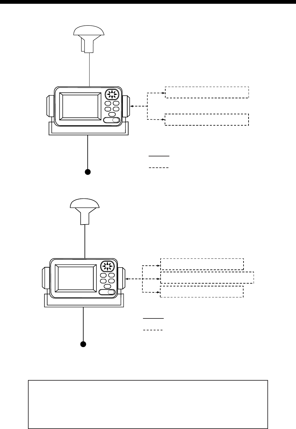
SYSTEM CONFIGURATION
Note: This equipment is intended for use on marine vessels. Do not use it in other applications.
NAVIGATOR
PERSONAL COMPUTER
PROCESSOR UNIT*
FURUNO GPS NAVIGATOR
12/24 VDC
* = With DGPS beacon receiver
ANTENNA UNIT
GPA-019
: Standard Supply
: Option
GP-37 system configuration
NAVIGATOR
PERSONAL COMPUTER
PROCESSOR UNIT
ANTENNA UNIT
GPA-017
FURUNO GPS NAVIGATOR
DGPS BEACON RECEIVER
12/24 VDC
: Standard Supply
: Option
GP-32 system configuration
This GPS receiver complies with Canadian standard RSS-210 (Low Power
License-Exempt Radio communication Devices).
Operation is subject to the following two conditions:
(1) this device may not cause interference, and
(2) this device must accept any interference, including interference that may
cause undesired operation of the device.
vii
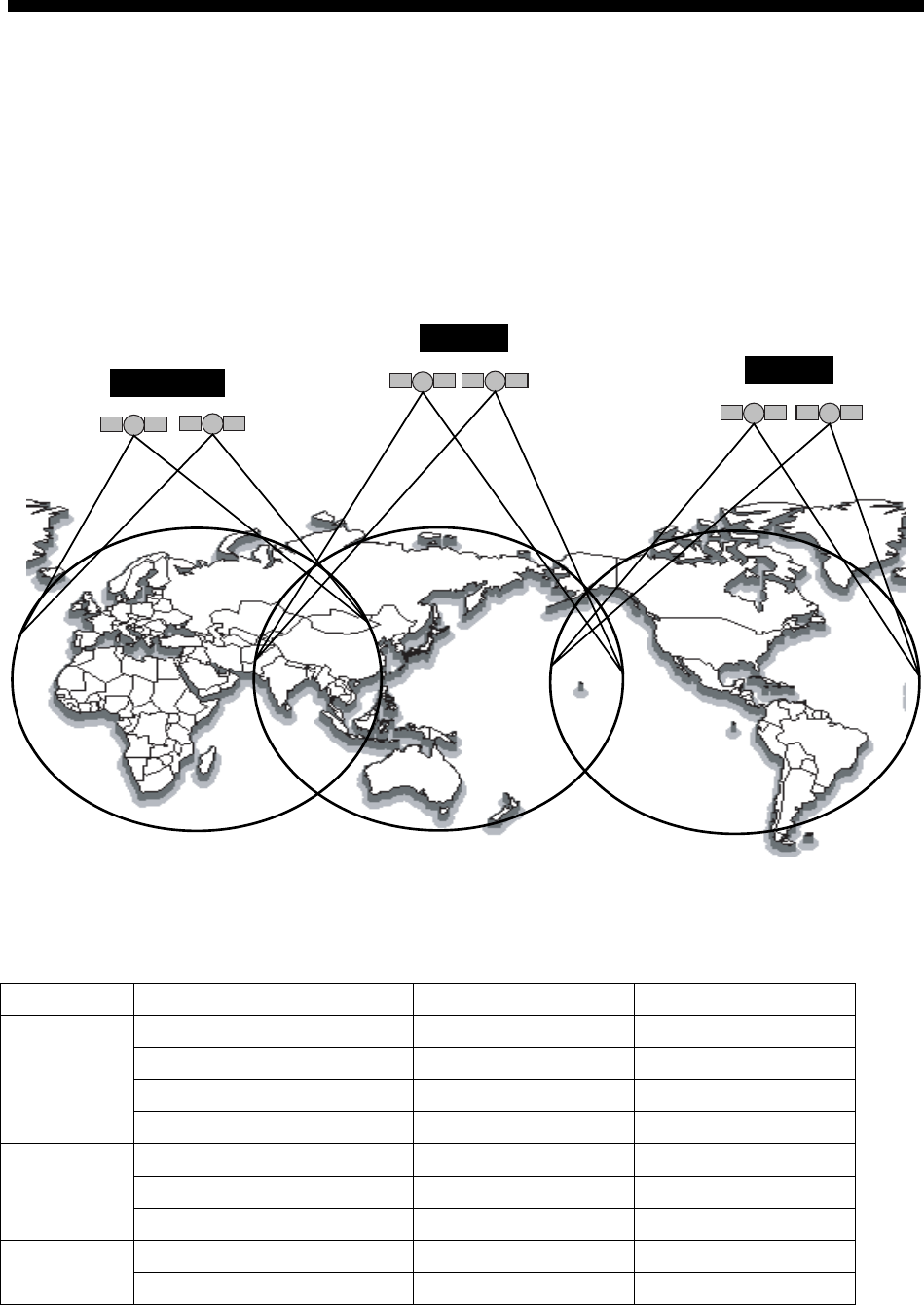
WHAT IS WAAS?
WAAS, available in North and South America mainly, is a provider in the worldwide SBAS
(Satellite Based Augmentation System) navigation system. SBAS provides GPS signal
corrections to SBAS users, for even better position accuracy, typically better than three
meters. There are two more SBAS providers, MSAS (Multi-Functional Satellite
Augmentation System) and EGNOS (Euro Geostationary Navigation Overlay Service). All
providers are compatible with one another, thus providing seamless position fixes to SBAS
users. The illustration below shows the coverage area of the SBAS. (Accuracy may be
affected when using a GEO satellite not within your current location.) This manual uses
WAAS for these three providers generically.
WAAS
MSAS
EGNOS
Provider Satellite type Longitude Satellite No.
Inmarsat-3-F4 142°E 122
Inmarsat-3-F3 (POR) 178°E 134
Intelsat Galaxy XV 133°W 135
WAAS
TeleSat Anik FIR 107.3°W 138
Inmarsat-3-F2 (AOR-E) 15.5°W 120
Artemis 21.5°E 124
EGNOS
Inmarsat-3-F5 (IOR-W) 25°E 126
MTSAT-1R 140°E 129 MSAS
MTSAT-2 145°E 137
.

viii
EQUIPMENT LISTS
Standard supply
Name Type Qty Remarks
GP-37
Display
Unit GP-32 1 With hanger, knob
GPA-019 1 For GP-37, w/10 m cable
Antenna
Unit GPA-017 1 For GP-32, w/10 m cable
Installation
Materials
CP20-02310 1 set • Power/data cable (1 pc.)
(Type: MJ-A7SPF0009-020C, Code No.: 000-159-686-10)
• Tapping screw (4 pcs.)
(Type: 5X20, Code No.: 000-162-608-10)
Spare Parts SP20-01001 1 set Fuse (2 pcs.)
(Type: FGMB 125V 1A PBF, Code No.: 000-157-478-10)
Template C42-00201 1 Code No. 000-809-299, flush mounting template
Hard Cover FP14-02801 1 Code No. 004-366-960
Optional equipment
Name Type Code No. Qty Remarks
Right Angle
Antenna Base
NO.13-QA330 000-803-239 1
L-type Antenna
Base
NO.13-QA310 000-803-240 1
Handrail
Antenna Base
NO.13-RC5160 000-806-114 1
Mast Mounting
Kit
CP20-01111 004-365-780 1 set
For mounting the antenna
unit, choose one
Cable Assy. MJ-A7SPF0009-020C 000-159-686-10 1
Flush Mounting
Kit F
OP20-29 000-041-405 1 set
Flush Mounting
Kit S
OP20-17 000-040-720 1 set
For flush mounting the
display unit, choose one
1
1. OPERATIONAL OVERVIEW
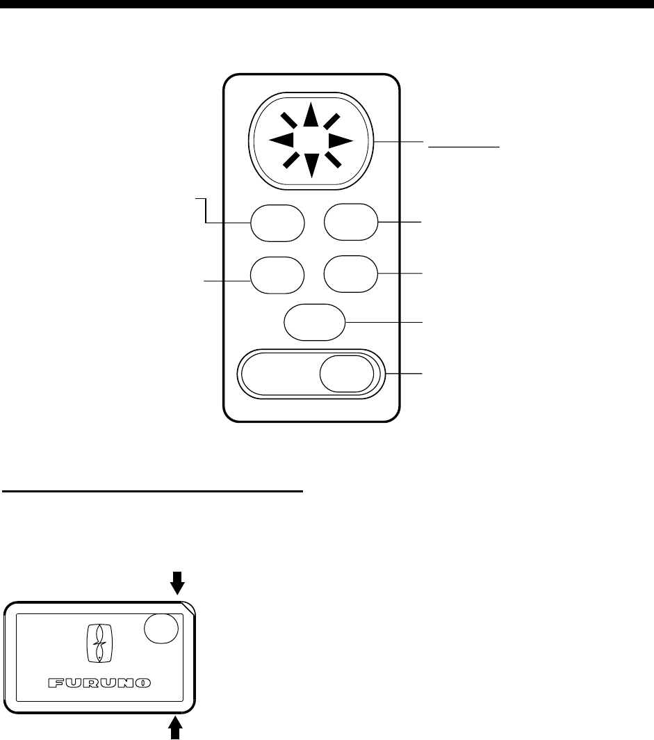
1.1 Controls
Press once: Zoom, centering,
or escapes from current opera-
tion, depending on display in
use.
Press twice: Opens menu.
Chooses display mode.
Momentary press: Turns
power on. With the power on, press
to adjust dimmer and contrast.
Long press: Turns power
off.
Momentary press: Inscribes mark.
Long press: Inscribes MOB mark.
Sets/cancels destination.
Registers items on menus.
Cursor Pad
• Shifts cursor (cursor displayed)
and display (cursor off).
• Selects items on menus.
• Enters alphanumeric data.
MENU
DIM
PWR
MARK
MOB
ENT
DISP GOTO
Control panel
How to attach and remove the hard cover
To attach the hard cover, set it to the display unit at an angle.
To remove the hard cover, do as follows:
Press at arrows
and pull toward
you to remove.
1. OPERATIONAL OVERVIEW
2
1.2 Turning On and Off Power
Turning on the power
Press the [DIM/PWR] key. The unit beeps
and then starts up with the last-used display
mode.
Note: The example screens shown in this
manual may not match the screens you see
on your display. The screen you see depends
on your system configuration and equipment
settings.
Your equipment takes about 90 seconds to
find its position when turned on for the very
first time. Thereafter it typically takes about
12 seconds.
The equipment shows receiver status
indication at the top left-hand corner in most
display modes. The table below shows these
indications and their meanings.
Receiver status indications
Indication Meaning
2D 2D GPS position fix
3D 3D GPS position fix
D2D 2D DGPS position fix
D3D 3D DGPS position fix
W2D 2D WAAS position fix
W3D 3D WAAS position fix
DOP* 2D: HDOP larger than 4
3D: PDOP larger than 6
SIM Simulation mode
* = DOP (Dilution of Precision) is the index of
position accuracy and is the distribution
pattern of satellites used in position fixing.
Generally, the smaller the figure the better the
position accuracy.
Turning off the power
Press and hold down the [DIM/PWR] key until
the screen goes blank (about three seconds).
The time remaining until the power is turned
off is counted down on the display.
1.3 Adjusting Brilliance and
Contrast
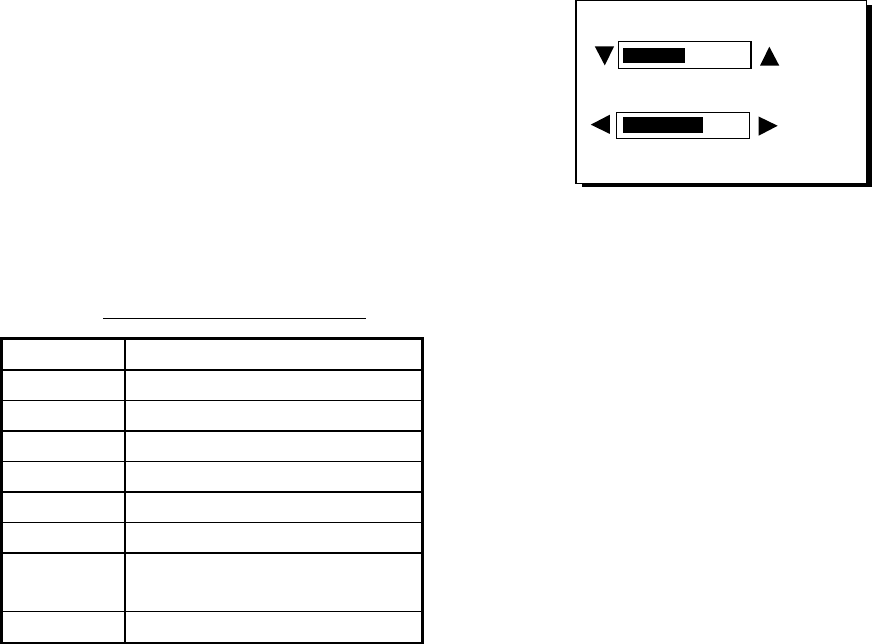
1. Press the [DIM/PWR] key momentarily.
The display shown below appears.
BRILL (1~8)
CONTRAST (0~63)
4
41
EXIT:[ENT]
Brilliance and contrast adjustment window
2. To adjust the brilliance, press ▲ or ▼.
Current setting is shown to the right of ▲.
Maximum setting is 8.
3. To adjust the contrast, press ◄ or ►.
Current setting is shown to the right of ►.
Maximum setting is 63.
4. Press the [ENT] key to finish.
Note: If the last-used contrast setting is 36 or
higher, the equipment starts up with that
setting. If the setting is 35 or lower, the
equipment starts up with setting 36.
1. OPERATIONAL OVERVIEW
3
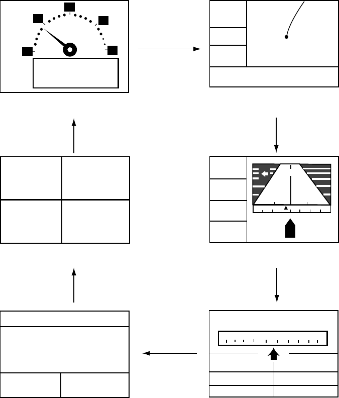
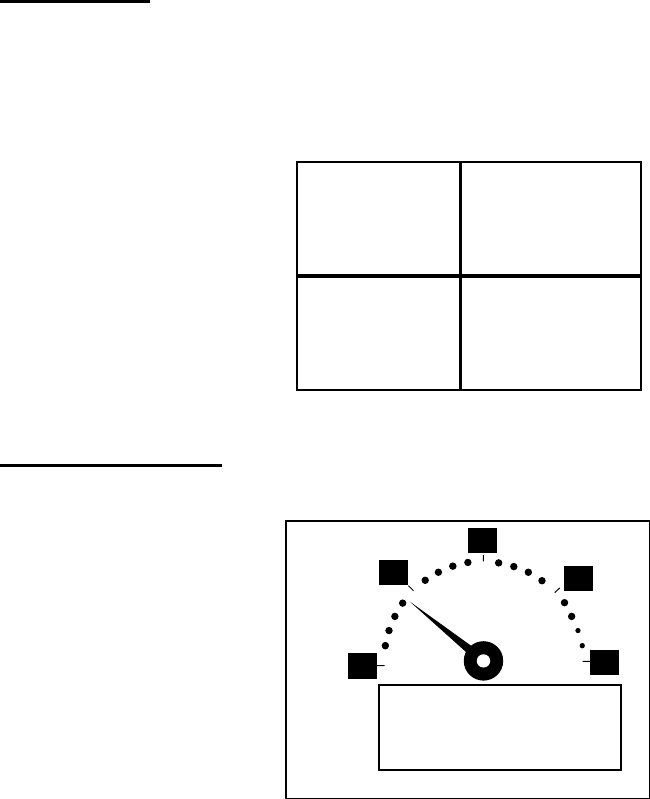
1.4 Display Modes
Your unit has five display modes: Plotter Display, Highway Display, Steering Display, Nav Data
Display and User Display (digital data and speedometer). Press the [DISP] key to choose a
display mode. Each time the key is pressed, the display mode changes in the sequence shown
below.
[Highway Display]
COG
BRG
RNG
SOG
0.5
XTE
0.05
242°
0.05 0.05
17.5
004
n
m
[Plotter Display]
D2D
[ 5 ]
n
m
SOG:
10.0 k
t
34°44.000N 135°21.000E
X
D2D MAG 15:37
NE
30 60
300 330
SOG: kt COG:
RNG: BRG:
TTG: ETA:
1H30M 12:30
17.5 nm 242°
[Steering Display]
(Display format
depends on user setting.)
CURSOR
[+]
n
m
k
t
[Nav Data Display]
D2D
02-FEB-02 15:37:40
SOG: kt COG:
34°44. 000'
N
135°21. 000'
E
10.0 357°
COG:
357°
357°
10.0
10.0 357°
[User Display: Speedometer]
(Display format
depends on user setting.)
20
30
40
60
0
10
0
9.9
KT
SOG
[User Display: Digital Data]
POWER(V) SOG(KT)
TRIP(NM) COG(°)
9.99 5.6
12.1 9.9
[DISP] key
[DISP] key
[DISP] key
[DISP] key
[DISP] key
[DISP] key
Display modes (default user displays)
Note 1: The unit measures distances up to 9999 nm. Any distance greater than 9999 nm is
shown as “*999”.
Note 2: Position data can be shown in latitude and longitude or TDs (Loran C or Decca).
1. OPERATIONAL OVERVIEW
4
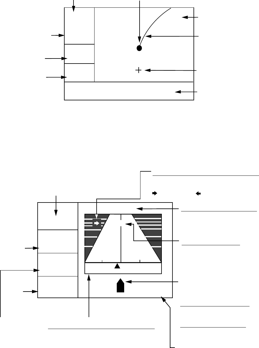
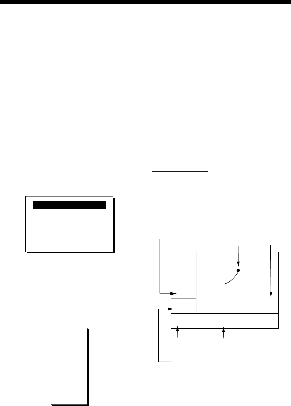
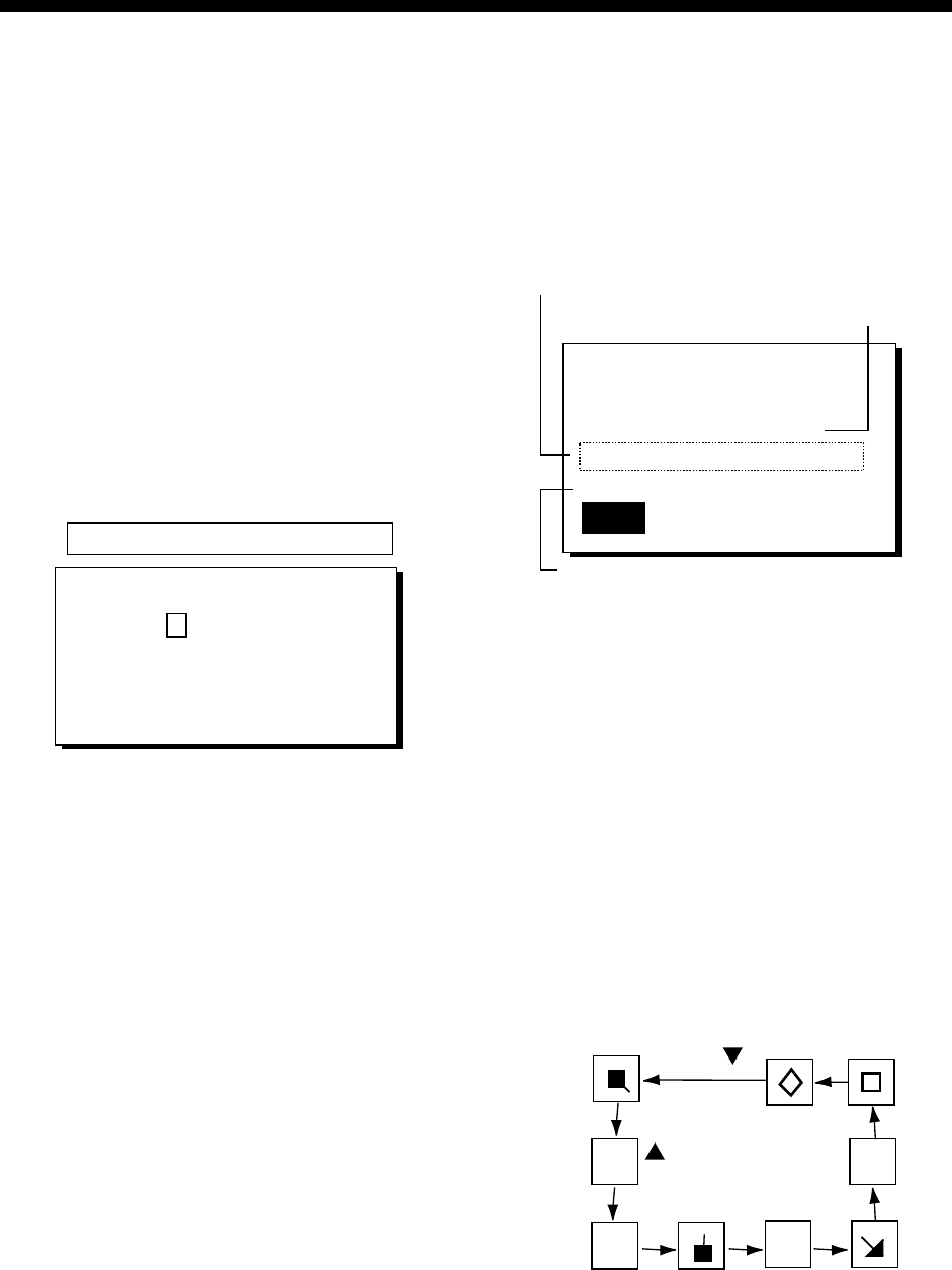
Plotter display
The plotter display traces own ship’s track, and shows position, bearing to cursor, range to
cursor, horizontal display range setting and receiver status.
D2D
[ 40 ]
n
m
12.0
n
m
34°44.000N 135°21.000E
X
Own ship mark (blinking)
Receiver status
(See table on page 2.)
Cursor
(Displayed six seconds.)
Waypoint mark
(Shape selectable)
Horizontal display
range setting
Range
to cursor*
Bearing
to cursor*
Boat's track
RNG: +
BRG: +
* = COG and SOG replace bearing to cursor and
range to cursor when the cursor is not displayed.
180°
Cursor position
(Own ship position when
cursor is not displayed.)
Plotter display
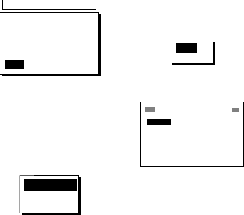
Highway display
The highway display provides a 3-D view of own ship’s progress toward destination (waypoint).
Nav data is also shown.
9.0
n
m
RNG
11°
SOG n
m
N
Bearing from own ship to
destination waypoint
Speed
over
ground
0.3
XTE
0.05
BRG
COG
11°
k
t
12.5
Course
over
ground
CURSOR Destination waypoint name
"CURSOR" (cursor-selected
destination) or waypoint name
Digital XTE indication
(in nautical miles)
[+]
0.5 0.5
Range from
own ship to
destination
waypoint
Analog XTE (Cross-track error) scale
Arrow shifts with boat's XTE. When the
arrow is aligned with the centerline
the boat is on course. The arrow blinks if
boat's XTE is greater than XTE scale
range. "N" (North) is displayed instead of
the arrow when no destination is set.
Destination waypoint
Moves forward as boat
nears destination.
Direction to steer (to return to course)
Appears to right or left of centerline
depending on direction to steer;
: Steer right, : Steer left.
I I I I I I I
∆ C (Delta Course)
The boat mark displays
course as follows:
When no waypoint is set;
The mode is North-up and
the arrow shows boat's course.
When a waypoint is set;
The arrow shows boat's
course towards destination.
Highway display
1. OPERATIONAL OVERVIEW
5
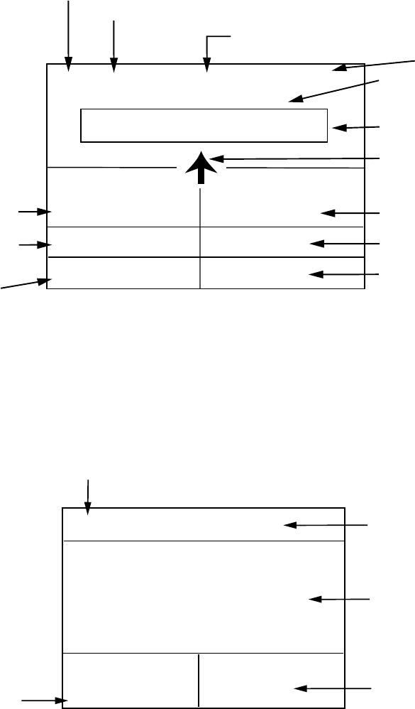
Steering display
The steering display provides steering information such as ship’s speed, course, range, bearing,
ETA and TTG.
D2D MAG
COG:
60°
SOG:
12.5
kt
W 300 330 N 30 60 E
04:32
Bearing scale
Bearing reference (MAG or TRUE)
Speed over ground
I I I I I I I I I I I I I
354°
RNG: BRG:
TTG: ETA: 1H 30M 12:30
CURSOR
▼
Receiver status
Bearing
Time-To-Go
to destination
(*9H*9M is displayed
when TTG is over 99 h59min.)
Own ship mark
Course over ground
Time
0.16 nm
Destination (CURSOR or waypoint name)
Bearing from own ship
to destination
Estimated Time of
Arrival at destination
(*9:*9 shown when
ETA is over 99h59min.)
Range from own ship
to destination
Steering display
Nav data display
The nav data display shows receiver status, position in latitude and longitude (or TDs), course
over ground, speed over ground, date and time.
D2D
COG:SOG:
12.5
kt
34°44.000'
135°21.000'
10-JAN-02 16 :44 :15
N
E
Date and time
Course over ground
Speed over ground
7
°
Position in latitude
and longitude
Receiver status
Nav data display
1. OPERATIONAL OVERVIEW
6
User displays
Two user displays are available, digital and speedometer.
Digital display
The digital display shows digital navigation data. The user may choose what data to display in
one to four cells. The choices of data are time, speed over ground, cross-track error, odometer
distance, position, course over ground, time-to-go to destination, trip distance, power source
voltage, range and bearing to waypoint, and estimated time of arrival at destination.
POWER(V) SOG(KT)
TRIP(NM) COG(°)
9.99 5.6
12.1 9.9
Digital display (default display)
Speedometer display
The speedometer display provides both digital and analog displays of speed over ground.
20
30
40
60
0
10
0
9.3
KT
SOG
Speedometer display

1. OPERATIONAL OVERVIEW
7
1.5 Menu Overview
Most operations of your unit are carried out
through the menu. Below is a quick
introduction to how to choose a menu and
change menu settings. If you get lost in
operation, press the [MENU] key to return to
the MAIN MENU. For your reference, a
complete menu tree appears in the Appendix.
1. Press the [MENU] key once or twice to
display the menu.
One press: Steering display, nav data
display and user display.
Two presses: Plotter display, highway
display.
MAIN MENU
WAYPOINTS
ROUTES
PLOTTER
ALARMS
ERASE
WAAS/DGPS
CALCULATE
MESSAGES
SATELLITE
USER DISP
GPS SETUP
SYS SETUP
I/O SETUP
TD SETUP
Main menu
2. Operate the cursor pad to choose a menu
and then press the [ENT] key. For
example, choose PLOTTER and then
press the [ENT] key.
PLOTTER SETUP
TRACK REC : DISTANCE
INTERVAL : 0.10 nm
BRG. REF. : MAG
MAG. VAR. : AUTO E16
WPT NAME : DSP GOTO
TTG/ETA SPD : AUTO
TRACK MEMORY USED 1%
PLOTTER SETUP menu
3. Use ▲ or ▼ to choose menu item. For
example, choose TRACK REC.
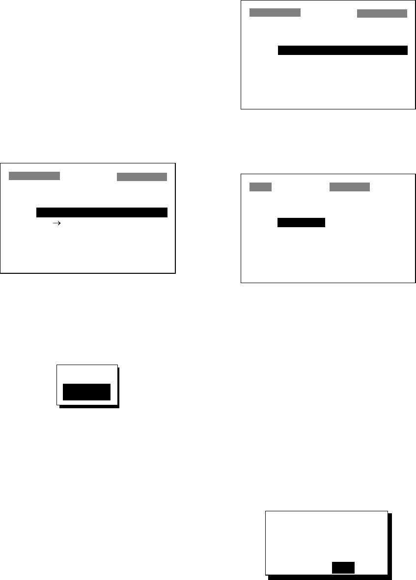
4. Press the [ENT] key. A window shows the
options for the item selected. (The
illustration at the top of the next shows the
options available for TRACK REC.)
OFF
DISTANCE
AUTO
Track recording options
5. Press ▲ or ▼ to choose option desired.
6. Press the [ENT] key to register your
selection.
7. Press the [MENU] key twice to close the
menu.
How to enter alphanumeric data
In some instances it is necessary to enter
alphanumeric data. The example below
shows how to enter a time difference of -6:30,
to use local time instead of UTC time.
1. Press the [MENU] key once or twice to
display the menu.
2. Choose SYS SETUP and then press the
[ENT] key.
SYSTEM SETUP
LANGUAGE : ENGLISH
DATUM : WGS84
UNITS : nm, kt
TIME DIFF : +00 : 00
TIME DISP : 24HOUR
TEST?
SIMULATOR?
EXCHANGE BATTERY?
SYSTEM SETUP menu
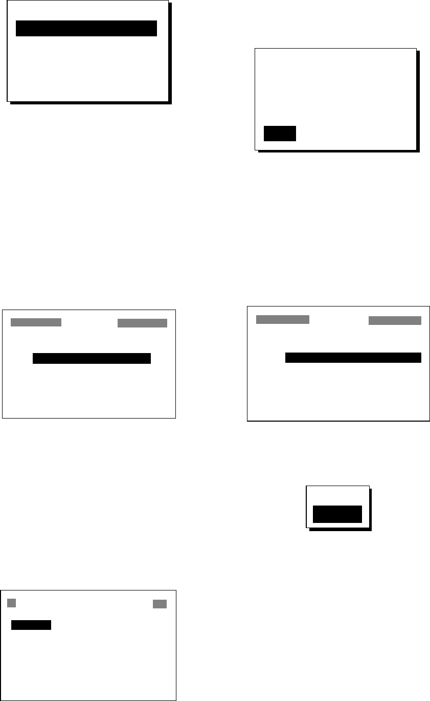
3. Choose TIME DIFF.
4. Press the [ENT] key. A cursor
circumscribes “+”. This cursor appears
whenever selected data can be changed
with the cursor pad.
SYSTEM SETUP
LANGUAGE : ENGLISH
DATUM : WGS84
UNITS : nm, kt
TIME DIFF : +00 : 00
TIME DISP : 24HOUR
TEST?
SIMULATOR?
EXCHANGE BATTERY?
SYSTEM SETUP menu,
TIME DIFF selected
1. OPERATIONAL OVERVIEW
8
5. Press ▲ to display “-“.
6. Press ► to send the cursor to the next
digit.
7. Press ▲ or ▼ to display “0.”
8. Press ► to send the cursor to the next
digit.
9. Press ▲ or ▼ to display “6.”
10. Press ► to send the cursor to the next
digit.
11. Press ▲ or ▼ to display “3.”
12. Press ► to send the cursor to the last
digit.
13. Press ▲ or ▼ to display “0.”
14. Press the [ENT] key.
15. Press the [MENU] key twice to finish.
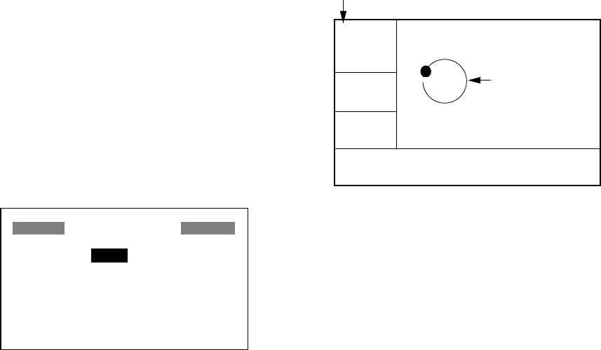
1.6 Simulation Display
The simulation display provides simulated
operation of this unit. You may set the speed
manually and course manually or
automatically. All controls are operative - you
may enter marks, set destination, etc.
1. Press the [MENU] key once or twice to
display the menu.
2. Choose SYS SETUP and then press the
[ENT] key.
3. Choose “SIMULATOR?” and then press
the [ENT] key. (Note that position shown
depends on language selected on the
SYS SETUP menu. After changing the
language, the memory is cleared.)
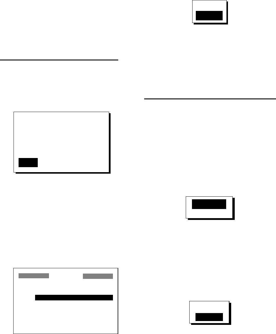
SIMULATOR
MODE : OFF
SPEED : 20 kt
COURSE : AUTO
LAT : 38°00'N
LON : 123°00'W
SIMULATOR menu
4. The cursor is selecting MODE. Press the
[ENT] key. A window shows the choices
ON and OFF.
5. Choose ON and then press the [ENT] key.
6. Press the [ENT] key, use the cursor pad
to enter speed to use for the simulation,
and then press the [ENT] key.
7. Press the [ENT] key.
8. Choose course (AUTO or MAN) and then
press the [ENT] key. For manual entry of
course, press the [ENT] key, enter course
with the cursor pad, and then press the
[ENT] key. The AUTO course tracks a
circular course.
Note: Course must be AUTO to set
simulation destination.
9. Press the [ENT] key, enter latitude with
the cursor pad, and then press the [ENT]
key.
10. Press the [ENT] key, enter longitude, and
then press the [ENT] key.
11. Press the [MENU] key twice.
12. Choose the PLOTTER display with the
[DISP] key. SIM appears at the upper
left-hand corner when the simulator
display is active.
SIM
[ 40 ]
n
m
COG:
82°
SOG:
9.0 k
t
34°44.000N 135°21.000E
Course traced
in AUTO course
Simulation mode active
Simulator display, auto course selected
13. To turn off the simulator display, choose
OFF at step 5 in this procedure, press the
[ENT] key and then press the [MENU] key
twice to finish.
Note: If the power is turned off while the
simulator display is in use, the indication
SIMULATION MODE appears at the top of
the screen at the next power up, in addition to
the indication SIM. SIMULATION MODE
disappears when any key is pressed,
however the simulation mode continues.
9
2. PLOTTER DISPLAY OVERVIEW
2.1 Choosing the Display
Range
You may choose the display range on the
plotter and highway displays. The horizontal
range in the plotter display is available among
0.02 (40 yd), 0.05 (101 yd), 0.1 (202 yd), 0.2
(405 yd), 0.5, 1, 2, 5, 10, 20, 40, 80, 160 and
320 nautical miles. (Nautical mile is the
default unit of display range. Display range
may also be shown in kilometers or miles.
Ranges shorter than the 0.5 nm are also
shown in yards or meters on the plotter
display.) The horizontal range in the highway
display is available among 0.2, 0.4, 0.8, 1, 2,
4, 8 and 16 nautical miles.
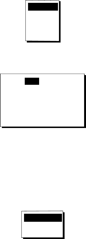
1. Press the [MENU] key. The zoom, ship
centering window appears.
ZOOM IN/OUT?
SHIP TO CENTER?
PRESS [MENU] TO SEE
THE MAIN MENU.
Quit?
Zoom, ship centering window
Note: “SHIP TO CENTER?” does not
appear when the highway display mode is
active.
2. ZOOM IN/OUT is selected. Press the
[ENT] key to show the zoom window.
IN
OUT
▲
▼
20
EXIT:
[ENT]
n
m
ZOOM
Zoom window
3. Use ▲ (increase) or ▼ (decrease) to
choose range desired.
4. Press the [ENT] key to close the zoom,
ship centering window.
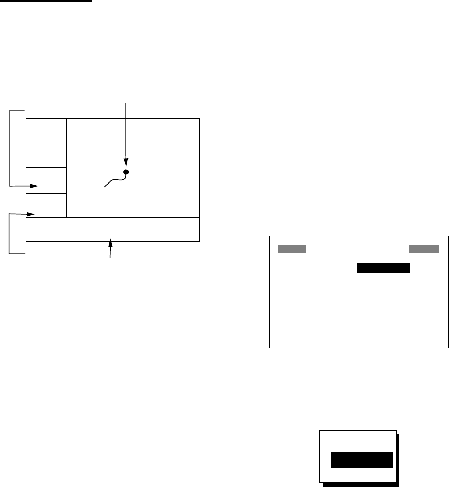
2.2 Shifting the Cursor
Use the cursor pad to shift the cursor. The
cursor moves in the direction of the arrow or
diagonal pressed on the cursor pad.
Cursor state and data
Cursor state determines what data is shown
on the display.
Cursor turned on
Cursor position is displayed in latitude and
longitude or TDs (depending on menu
setting) at the bottom of the plotter display
when the cursor is on. The range and bearing
from own ship to the cursor appear at the
left-hand side of the display.
D2D
[ .02
]
n
m
BRG: +
131°
RNG: +
0.03
n
m
+ 34°44.000N 135°21.000E
Bearing from own
ship to cursor
Cursor position in
latitude and longitude
Cursor mark
Cursor
Range from own ship to cursor
Own ship
40 y
d
Plotter display, cursor turned on
2. PLOTTER DISPLAY OVERVIEW
10
Cursor turned off
The cursor is erased when there is no cursor
pad operation for about six seconds. Ship’s
position, speed and course appear when the
cursor is off.
D2D
[ 40 ]
n
m
COG:
7°
SOG:
9.0 k
t
34°44.111N 135°20.555E
Own ship's position in
latitude and longitude
Own ship's position
(Blinking)
Course over ground
Speed
over
ground
Plotter display, cursor turned off
2.3 Shifting the Display
The display can be shifted on the plotter
display. Operate the cursor pad to place the
cursor at an edge of the screen. The display
shifts in the direction opposite to cursor pad
operation.
2.4 Centering Own Ship’s
Position
When own ship tracks off the plotter display,
the own ship mark is automatically returned
to the screen center. You can also return it
manually as follows:
1. Press the [MENU] key.
2. Choose “SHIP TO CENTER?”.
3. Press the [ENT] key.
2.5 Changing Track Plotting
Interval, Stopping Plotting
To trace the ship’s track, the ship’s position is
stored into the memory at an interval of
distance or according to display range. For
distance, a shorter interval provides better
reconstruction of the track, but the storage
time of the track is reduced. When the track
memory becomes full, the oldest track is
erased to make room for the latest.
1. Press the [MENU] key once or twice to
display the menu.
2. Choose PLOTTER.
3. Press the [ENT] key.
PLOTTER SETUP
TRACK REC : DISTANCE
INTERVAL : 0.10 nm
BRG. REF. : MAG
MAG. VAR. : AUTO E16
WPT NAME : DSP GOTO
TTG/ETA SPD : AUTO
TRACK MEMORY USED 1%
PLOTTER SETUP menu
4. The cursor is selecting TRACK REC.
Press the [ENT] key to show the track
recording method options.
OFF
DISTANCE
AUTO
Track recording method options
5. Choose OFF, DISTANCE or AUTO and
then press the [ENT] key.
OFF: Track is neither recorded nor
plotted. This setting is useful when you do
not need to record track, for example,
when returning to port.
DISTANCE: Track is recorded and
plotted at the distance interval set.
AUTO: Plotting and recording interval
changes with display range selected.

2. PLOTTER DISPLAY OVERVIEW
11
6. For AUTO or OFF, go to step 7. For
DISTANCE, enter the recording interval
as follows:
a) Press the [ENT] key.
b) Use ◄ or ► to choose digit to change.
c) Use ▲ or ▼ to change value.
d) Press the [ENT] key after setting the
recording interval.
7. Press the [MENU] key twice to finish.
2.6 Erasing Track
All track can be erased. Track cannot be
restored once erased, therefore be absolutely
sure you want to erase all track.
1. Press the [MENU] key once or twice to
display the menu.
2. Choose ERASE and then press the [ENT]
key to display the ERASE menu.
WAYPOINTS/MARKS?
ROUTES?
TRACK?
RESET TRIP? (6.40nm)
RESET ODO? (6.40nm)
GPS DATA?
MENU SETTINGS?
ALL BACKUP DATA?
ERASE
ERASE menu
3. Choose “TRACK?” and then press the
[ENT] key. The message shown below
appears.
ERASE TRACK.
ARE YOU SURE?
YES NO
Prompt for erasure of track
4. Press ◄ to choose YES and then press
the [ENT] key.
5. Press the [MENU] key twice to finish.
2. PLOTTER DISPLAY OVERVIEW
12
(This page intentionally left blank.)
13
3. WAYPOINTS (MARKS)
3.1 Entering Waypoints
In navigation terminology a waypoint is a
particular location on a voyage, whether it be
a starting, intermediate or destination
waypoint. Your unit can store 999 waypoints.
Waypoints can be entered on the plotter
display three ways: at cursor position, at own
ship’s position, and from the waypoint list.
Entering a waypoint with the cursor
1. Use the cursor pad to place the cursor on
the location desired for a waypoint.
2. Press the [ENT] key. The following
window appears.
CURSOR POS. → WPT
ENTER A NEW WPT NAME.
0 0 1_ _ _?
(001:DEFAULT NAME)
QUIT: [MENU]
Waypoint name entry window
3. The cursor is on the second line of the
display. This is where you may enter
waypoint name, which may consist of six
alphanumeric characters. The number
shown is the youngest empty waypoint
number. If you would rather have the unit
register the waypoint under that number,
and you do not need to change mark
shape or enter a comment, press the
[ENT] key twice to register the waypoint
and finish. To enter KOBE as the
waypoint name, for example, do the
following:
a) Press ▲ or ▼ to display K.
b) Press ► to move the cursor one place
and then press ▲ or ▼ to display O.
c) Press ► to move the cursor one place
and then press ▲ or ▼ to display B.
d) Press ► to move the cursor one place
and then press ▲ or ▼ to display E.
e) Press the [ENT] key. The following
window appears.
NAME: KOBE
34°39.836'N MARK
135°12.059'E x
10-JAN-02 10:25
TTG 02H00M ETA: 12:25
Exit? LOG RTE?
TTG and ETA calculated according
to speed set at TTG/ETA SPEED on
PLOTTER menu.
Mark shape
Comment (default: date/time)
Waypoint attribute edit window
4. This window is where you can choose
mark shape, enter a comment, and log
the waypoint to a route (LOG RTE?). (If
you do not need to change mark shape or
enter a comment, choose “Exit?” and then
press the [ENT] key to finish. “LOG RTE?”
is discussed in chapter 4.)
a) Use the cursor pad to place the cursor
under “MARK.”
b) Press the [ENT] key.
c) Use ▲ or ▼ to choose mark desired.
H
+I
X
Press .
Note: Operating
changes the
sequence reversely.
Mark selection sequence
3. WAYPOINTS (MARKS)
14
d) Press the [ENT] key. The cursor is
selecting date/time, the default
comment. Press the [ENT] key.
e) Enter a comment (max. 16
alphanumeric characters) with the
cursor pad and then press the [ENT]
key. To create a space, choose the
“blank” character. To remove all
characters which follow the cursor,
choose the underline.
f) The cursor is on “Exit?.” Press the
[ENT] key to finish.
Entering a waypoint at own ship
position
1. Press the [MARK/MOB] key momentarily
on any display. The following window
appears.
NAME: 001
34°39.836'N MARK
135°12.059'E x
10-JAN-02 10:25D*
TTG 02H00M ETA: 12:25
Exit? LOG RTE?
GPS POS. → MARK
* D = Position fixed by DGPS
W = Position fixed by WAAS
Waypoint attribute edit window
2. If you want to register the waypoint under
the number shown, and you do not need
to change mark shape or enter a
comment, press the [ENT] key to finish.
3. To change name, choose NAME, press
the [ENT] key, enter name with the cursor
pad, and then press the [ENT] key. The
display below appears.
CREATE?
RENAME?
Quit?
Create, rename, quit options
4. Create is selected; press the [ENT] key.
5. To change mark shape, place the cursor
under “MARK.” Press the [ENT] key, use
▲ or ▼ to choose mark desired, and then
press the [ENT] key again.
6. The cursor is selecting date/time. To
change the date/time to your own
comment, press the [ENT] key, enter a
comment with the cursor pad, and then
press the [ENT] key again.
7. Place the cursor on “Exit?.” Press the
[ENT] key to finish.
Entering a waypoint from the waypoint
list
1. Press the [MENU] key once or twice to
display the menu.
2. Choose WAYPOINTS.
3. Press the [ENT] key to show the waypoint
list options. Choose LIST. (NEAREST
displays waypoints from nearest to
furthest; however, waypoints cannot be
entered from this display.)
LIST
NEAREST
Waypoint list options
4. Press the [ENT] key. The WPTS/MARKS
list appears.
WPTS/MARKS (LIST)
[NEW?] CURSOR MOB
START _ _ _ _ _ _ _ _ _ _ _ _
_ _ _ _ _ _ _ _ _ _ _ _ _ _ _ _ _ _
_ _ _ _ _ _ _ _ _ _ _ _ _ _ _ _ _ _
_ _ _ _ _ _ _ _ _ _ _ _ _ _ _ _ _ _
_ _ _ _ _ _ _ _ _ _ _ _ _ _ _ _ _ _
_ _ _ _ _ _ _ _ _ _ _ _ _ _ _ _ _ _
WPTS/MARKS list
CURSOR: Cursor position when
destination is set with cursor.
MOB: Man overboard position.
START: Starting point when destination
is selected.
3. WAYPOINTS (MARKS)
15
5. The cursor is selecting “NEW?”; press the
[ENT] key.
ENTER A NEW WPT NAME.
0 0 4_ _ _?
(004:DEFAULT NAME)
Quit: [MENU]
Waypoint name entry window
6. Enter name (if desired) with the cursor
pad and then press the [ENT] key.
NAME: 004
34°39.836'N* MARK
135°12.059'E* x
10-JAN-02 10:25D
TTG 02H00M ETA: 12:25
Exit? LOG RTE?
* Current position
Waypoint attribute edit window
7. The cursor is selecting latitude. Press the
[ENT] key. Enter latitude with the cursor
pad and then press the [ENT] key.
8. Press the [ENT] key, enter longitude in
similar fashion as you did with latitude and
then press the [ENT] key.
Note: To enter position by TDs, see
paragraph 7.7.
9. To change mark shape, choose the mark
currently shown and then press the [ENT]
key. Use ▲ or ▼ to choose mark desired
and then press the [ENT] key.
10. To change date and time to the comment
of your choice, press the [ENT] key, enter
comment with the cursor pad, and then
press the [ENT] key again.
11. Place the cursor on “Exit?.” Press the
[ENT] key.
12. Press the [MENU] key twice to finish.
3.2 Entering the MOB Mark
The MOB mark denotes man overboard
position. Only one MOB mark may be entered.
Each time the MOB mark is entered the
previous MOB mark and its position data are
written over.
1. Press the [MARK/MOB] key on any
display until the following display appears.
SAVED TO MOB.
GO TO MOB ?
ARE YOU SURE?
YES NO
MOB window
2. To set MOB position as destination, press
◄ to choose YES and then press the
[ENT] key. Then, the plotter display marks
MOB position as shown in the illustration
below.
Note: Selecting “NO” saves the position
as a waypoint.
D2D
[ 40
]
n
m
1°
0.06 n
m
34°44.000N 135°21.000E
BRG:
RNG:
MOB
MOB position set
as destination
Bearing and range to MOB position
Plotter display when MOB
is set as destination

3. WAYPOINTS (MARKS)
16
3.3 Displaying Waypoint
Name
You may display waypoint name as follows:
1. Press the [MENU] key once or twice to
display the menu.
2. Choose PLOTTER and then press the
[ENT] key.
3. Choose WPT NAME and then press the
[ENT] key to show the waypoint name
display options.
DSP GOTO
DSP RTE
DSP ALL
Waypoint name display options
4. Choose DSP GOTO, DSP RTE or DSP
ALL as appropriate and then press the
[ENT] key.
DSP GOTO: Displays only the GOTO
waypoint name.
DSP RTE: Displays all waypoint names
when a route is set as destination.
DSP ALL: Displays all waypoint names.
5. Press the [MENU] key twice to finish.
3.4 Operations on the
Waypoint List
Editing waypoints
Waypoint position, waypoint name, mark
shape and comment can be edited from the
WPTS/MARKS List.
1. Press the [MENU] key once or twice to
display the menu.
2. Choose WAYPOINTS and then press the
[ENT] key.
3. Choose LIST or NEAREST and then
press the [ENT] key.
4. Choose waypoint to edit and then press
the [ENT] key.
Note: CURSOR, MOB and START are
automatically updated according to
destination setting or MOB setting.
Therefore, editing these items has no
meaning.
5. Choose NAME and then press the [ENT]
key.
6. Change name with the cursor pad and
then press the [ENT] key. You are then
asked if you want to create or rename the
waypoint, or quit (escape) the display.
CREATE?
RENAME?
Quit?
Waypoint edit options
7. Choose objective desired and then press
the [ENT] key.
8. Change position, mark shape, comment
as desired.
9. Choose “Exit?” and then press the [ENT]
key.
10. Press the [MENU] key twice to finish.

3. WAYPOINTS (MARKS)
17
Showing nearest waypoints by
distance, TTG and ETA
1. Press the [MENU] key once or twice to
open the menu.
2. Choose WAYPOINTS and then press the
[ENT] key.
3. Choose NEAREST and then press the
[ENT] key. The display should look
something like the one shown below,
listing waypoints in order of distance from
own vessel, from closest to furthest.
WPTS/MARKS (NEAREST)
KOBE : 10.0 nm 344°
002 : 20.0 nm 337°
003 : 25.0 nm 357°
004 : 40.0 nm 143°
005 : 50.0 nm 90°
006 : 60.0 nm 200°
007 : 70.0 nm 320°
WPTS/MARKS list (NEAREST) by distance
4. To display ETA and TTG for each
waypoint, press ►.
WPTS/MARKS (NEAREST)
KOBE : 1H00M 12:00
002 : 2H00M 13:00
003 : 2H30M 13:30
004 : 4H00M 15:00
005 : 5H30M 16:30
006 : 6H00M 17:00
007 : 7H00M 18:00
WPTS/MARKS (NEAREST) list by TTG to ETA
5. To return to the waypoint list by distance,
press ◄.
6. Press the [MENU] key twice to close the
menu.
3.5 Erasing Waypoints
1. Press the [MENU] key once or twice to
display the menu.
2. Choose ERASE and then press the [ENT]
key.
WAYPOINTS/MARKS?
ROUTES?
TRACK?
RESET TRIP? (6.40nm)
RESET ODO? (6.40nm)
GPS DATA?
MENU SETTINGS?
ALL BACKUP DATA?
ERASE
ERASE menu
3. The cursor is selecting
“WAYPOINTS/MARKS?”. Press the [ENT]
key.
ERASE WPTS/MARKS
[ALL?] CURSOR KOBE
MOB START 001
002 003 004
005 006 007
_ _ _ _ _ _ _ _ _ _ _ _ _ _ _ _ _ _
_ _ _ _ _ _ _ _ _ _ _ _ _ _ _ _ _ _
_ _ _ _ _ _ _ _ _ _ _ _ _ _ _ _ _ _
ERASE WPTS/MARKS display
4. Choose the waypoint you want to erase.
Note: You cannot erase CURSOR, MOB
or START. To erase all waypoints, choose
ALL.
5. Press the [ENT] key. A screen showing
position and other particulars of the
waypoint selected appears.
NAME: KOBE
34°39.836'N MARK
135°12.059'E x
10-JAN-02 10:25D
TTG 02H00M ETA: 12:25
Quit?
ERASE?
Waypoint data
6. Press ► to choose “ERASE?” and then
press the [ENT] key.
7. Press the [MENU] key twice to finish.
3. WAYPOINTS (MARKS)
18
3.6 Speed for Calculating
Time-to-Go, Estimated
Time of Arrival
To calculate time-to-go and estimated time of
arrival, enter your speed as below.
1. Press the [MENU] key once or twice to
open the menu.
2. Choose PLOTTER and then press the
[ENT] key.
3. ChooseTTG/ETA and then press the
[ENT] key.
4. Choose AUTO for automatic speed input
(GPS calculated speed), or MAN for
manual input.
5. Press the [ENT] key.
6. For automatic speed input, go to step 7.
For manual speed input, press the [ENT]
key, enter speed with the cursor pad and
then press the [ENT] key.
7. Press the [MENU] key twice to finish.
19
4. ROUTES
In many cases a trip from one place to
another involves several course changes,
requiring a series of waypoints which you
navigate to, one after another. The sequence
of waypoints leading to the ultimate
destination is called a route. Your unit can
automatically advance to the next waypoint
on a route, so you do not have to change the
destination waypoint repeatedly.
4.1 Creating Routes
You can store up to 50 routes (numbered 01
to 50) and one LOG route, which is used to
temporarily store a route. A route may be
constructed four ways: by the cursor, by
waypoints entered from the waypoint list, by
waypoints entered from route menu, and by
storing current position automatically or
manually.
A route may contain 30 waypoints. When 30
waypoints have been saved, a message
informs you that you can no longer save
waypoints to the route. Press the [ENT] key
to erase the message and save the route,
under the name of the first and last waypoint
numbers used in the route.
Note: Be sure to record all important routes
in a separate log. This unit is not a fail-safe
record keeping device.
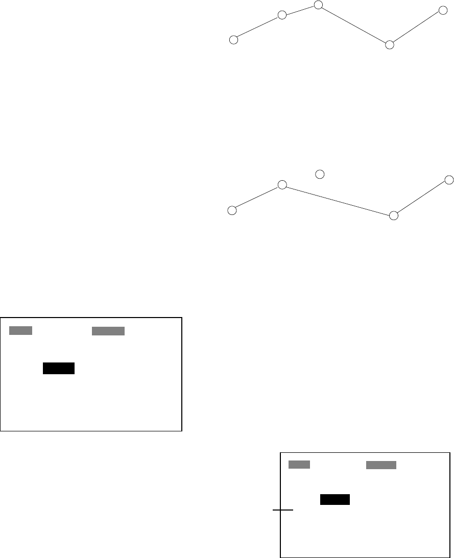
WAYPOINT
(Intermediate point) WAYPOINT
(Arrival point)
WAYPOINT
(Intermediate point)
WAYPOINT
(Intermediate point)
WAYPOINT
(Starting point)
Sample route
Creating a route with the cursor
This is probably the easiest method by which
to create a route.
1. Use the cursor pad to place the cursor on
position desired. (Cursor position is
shown at the bottom of the screen.)
2. Press the [ENT] key. The following
window appears.
CURSOR POS. → WPT
ENTER A NEW WPT NAME.
0 0 1_ _ _?
(001:DEFAULT NAME)
QUIT: [MENU]
Waypoint name entry window
The cursor is on the second line of the
display. This is where you may enter
waypoint name. The number shown is the
youngest empty waypoint number. If you
want to register the waypoint under that
number, and you do not need to change
mark shape or enter a comment, press
the [ENT] key to register the waypoint,
and then go to step 5.
3. If desired, change the waypoint name.
Press the [ENT] key.
NAME: 004
34°39.836'N* MARK
135°12.059'E* x
10-JAN-02 10:25D
TTG 02H00M ETA: 12:25
Exit? LOG RTE?
* Current position
Waypoint attribute edit window
4. ROUTES
20
4. If necessary, change waypoint, position,
mark shape, and comment (date and
time).
5. Choose “LOG RTE?” and then press the
[ENT] key.
6. Repeat steps 1 through 5 to complete the
route.
7. When you have entered all the waypoint
positions desired, press the [MENU] key
twice, choose ROUTES and then press
the [ENT] key.
ROUTES
VOYAGE ROUTE: STOP
INTERVAL: TIME 00H10M
NO [NEW?]
LOG 001
003
_ _ _ _ _ _ _ _ _ _ _ _ _ _ _ _ _ _
_ _ _ _ _ _ _ _ _ _ _ _ _ _ _ _ _ _
_ _ _ _ _ _ _ _ _ _ _ _ _ _ _ _ _ _
ROUTES menu
8. “LOG” shows the first and last waypoints
entered for the log route you are currently
creating. Choose LOG and then press the
[ENT] key.
EDIT?
MOVE?
Route processing options
9. “MOVE?” is selected; press the [ENT] key.
The route is moved from “LOG” and is
registered under the next sequential route
number. (To edit the route before saving it,
choose ”EDIT?”. For how to edit a route,
see paragraph 4.2.)
Creating a route from the route menu
The procedure which follows describes how
to create a route from two preregistered
waypoints, KOBE and OSAKA.
1. Press the [MENU] key once or twice to
display the menu.
2. Choose ROUTES.
3. Press the [ENT] key.
ROUTES
VOYAGE ROUTE: STOP
INTERVAL: TIME 00H1M
NO [NEW?]
LOG EMPTY ROUTE
01 001 → 003
_ _ _ _ _ _ _ _ _ _ _ _ _ _ _ _ _ _
_ _ _ _ _ _ _ _ _ _ _ _ _ _ _ _ _ _
ROUTES list
4. “NEW?” is selected; press the [ENT] key.
The screen shown below appears.
ROUTE-01
CMNT: EMPTY ROUTE
TOTAL DISTANCE _ _ _ _ nm
01. _ _ _ _ _ _
02. _ _ _ _ _ _
03. _ _ _ _ _ _
04. _ _ _ _ _ _
05. _ _ _ _ _ _
Exit?
_ _ _ _ nm _ _ _°
_ _ _ _ nm _ _ _°
_ _ _ _ nm _ _ _°
_ _ _ _ nm _ _ _°
Screen for entering route by waypoint
5. Choose location (01, etc.) and then press
the [ENT] key. Use ▲ or ▼ to display
waypoint name. (In the example, KOBE.)
6. Press the [ENT] key.
7. Repeat steps 5 and 6 until you have
entered all waypoints desired.
Note: If you enter a waypoint which has
not been registered, your screen will show
a message which looks something like the
one below. Press ◄ to choose YES and
then press the [ENT] key to create a new
waypoint; choose NO to return to the
route entry screen.
NEW WPT NAME.
CREATE 008?
ARE YOU SURE?
YES NO
New waypoint creation screen
When you choose YES, the following
screen appears. Edit the waypoint as
necessary, choose “Exit?” and then press
the [ENT] key.
4. ROUTES
21
NAME: 008
34°39.836'N MARK
135°12.059'E x
10-JAN-02 11:25D
TTG 02H00M ETA: 12:25
Exit?
Waypoint attribute edit window
8. “CMNT” shows the name of the route: the
names of the first and last waypoints in
the route. If you want to change the name,
press ▲ to choose CMNT, press the
[ENT] key, enter route name with the
cursor pad and then press the [ENT] key.
9. Choose “Exit?” at the top of the screen.
10. Press the [ENT] key to register the route,
under the next sequential route number.
Then, the ROUTES list shows the name
of the first and last waypoints used, next
to route number.
ROUTES
VOYAGE ROUTE: STOP
INTERVAL: TIME 00H10M
NO [NEW?]
LOG EMPTY ROUTE
01 001 → 003
02 KOBE → OSAKA
_ _ _ _ _ _ _ _ _ _ _ _ _ _ _ _ _ _
ROUTES list
11. Press the [MENU] key twice to finish.
Creating a route from the waypoint list
1. Press the [MENU] key once or twice to
display the menu.
2. Choose WAYPOINTS and then press the
[ENT] key.
3. Choose LIST or NEAREST and then
press the [ENT] key.
WPTS/MARKS (LIST)
[NEW?] 001 002
003 CURSOR MOB
START _ _ _ _ _ _ _ _ _ _ _ _
_ _ _ _ _ _ _ _ _ _ _ _ _ _ _ _ _ _
_ _ _ _ _ _ _ _ _ _ _ _ _ _ _ _ _ _
_ _ _ _ _ _ _ _ _ _ _ _ _ _ _ _ _ _
_ _ _ _ _ _ _ _ _ _ _ _ _ _ _ _ _ _
WPTS/MARKS (list)
4. Choose a waypoint and then press the
[ENT] key. Your screen should look
something like the one below.
NAME: 001
34
°
39.836'N MARK
135
°
12.059'E x
10-JAN-02 10:25D
TTG 02H00M ETA: 12.25
Exit? LOG RTE?
Waypoint attribute edit window
5. Choose “LOG RTE?” and then press the
[ENT] key.
6. Repeat steps 4 and 5 to complete the
route.
7. Press the [MENU] key once.
8. Choose ROUTES and then press the
[ENT] key. Your screen should now look
something like the one shown below.
ROUTES
VOYAGE ROUTE: STOP
INTERVAL: TIME 00H10M
NO [NEW?]
LOG 004→ 006
01 001→ 003
02 KOBE → OSAKA
_ _ _ _ _ _ _ _ _ _ _ _ _ _ _ _ _ _
ROUTES list
9. Choose LOG and then press the [ENT]
key.
EDIT?
MOVE?
Route processing options
10. “MOVE?” is selected; press the [ENT]
key. The route is moved from LOG and
assigned the next sequential route
number.
11. Press the [MENU] key twice to finish.
4. ROUTES
22
Creating a track-based route
There are two methods by which you can
create a track-based route: manual input of
track points using the [MARK/MOB] key and
automatic input of track points from the
ROUTES menu. A track-based route is useful
for retracing your track.
Creating a track-based route manually
This method creates a route by storing
position each time the [MARK/MOB] key is
pressed.
1. Press the [MARK/MOB] key momentarily.
NAME: 001
34
°
39.836'N MARK
135
°
12.059'E x
10-JAN-02 10:25D
TTG 02H00M ETA: 12:30
Exit?
LOG RTE?
Waypoint attribute edit window
2. Change name, comment and mark shape
if desired. Choose “LOG RTE?” and then
press the [ENT] key.
3. Repeat steps 1 and 2 when you change
course.
4. When you have entered all the waypoint
positions desired, press the [MENU] key
twice, choose ROUTES and then press
the [ENT] key.
ROUTES
VOYAGE ROUTE: STOP
INTERVAL: TIME 00H10M
NO [NEW?]
LOG 001→ 003
01 KOBE → OSAKA
_ _ _ _ _ _ _ _ _ _ _ _ _ _ _ _ _ _
_ _ _ _ _ _ _ _ _ _ _ _ _ _ _ _ _ _
ROUTES menu
5. Choose LOG and then press the [ENT]
key.
EDIT?
MOVE?
Route processing options
6. “MOVE?” is selected; press the [ENT] key.
The route is moved from “LOG” and is
registered under the next sequential route
number.
7. Press the [MENU] key twice to finish.
Creating a track-based route automatically
This method creates a route by automatically
storing position at intervals of time or
distance.
1. Press the [MENU] key once or twice to
open the menu.
2. Choose ROUTES and then press the
[ENT] key.
3. Choose INTERVAL and then press the
[ENT] key.
TIME
DISTANCE
4. Choose TIME or DISTANCE (the method
by which position will be stored) as
appropriate and press the [ENT] key.
5. Press the [ENT] key. Use the cursor pad
to set time or distance value and then
press the [ENT] key.
6. Choose VOYAGE ROUTE and then press
the [ENT] key.
START
STOP
Voyage start options
7. Choose START and then press the [ENT]
key.
4. ROUTES
23
8. Press the [MENU] key twice to finish.
The current position is saved under the
next sequential waypoint number, the
display shows “***SAVED!” (*** =
waypoint number) and a beep sounds.
Thereafter waypoints are saved at the
interval of time or distance set.
When 30 waypoints have been saved, a
message informs you that you can no
longer save waypoints to the route. Press
the [ENT] key to erase the message. The
route is automatically saved to “LOG” in
the ROUTES menu, under the name of
the first and last waypoint numbers used.
Then, open the ROUTES menu and go to
step 13.
You can manually stop saving waypoints
and save the route by going to step 9.
9. After the desired number of waypoints
have been entered, press the [MENU] key
once or twice to open the menu.
10. Choose ROUTES and then press the
[ENT] key.
11. Choose VOYAGE ROUTE and then press
the [ENT] key.
12. Choose STOP and then press the [ENT]
key.
13. Choose LOG and then press the [ENT]
key.
14.“MOVE?” is selected; press the [ENT] key.
The route is moved from “LOG” and is
registered under the next sequential route
number.
15. Press the [MENU] key twice to finish.
4.2 Editing Routes
Replacing waypoints in a route
1. Press the [MENU] key once or twice to
display the menu.
2. Choose ROUTES and then press the
[ENT] key.
3. Choose the route to edit.
4. Press the [ENT] key.
5. Place the cursor on the waypoint to
replace.
6. Press the [ENT] key to show the route edit
options.
CHANGE?
REMOVE?
INSERT?
SKIP?
Quit?
Route edit options
7. “CHANGE?” is selected; press the [ENT]
key.
NAME: 001
34°39.836'N MARK
135°12.059'E x
10-JAN-02 10:25D
TTG 02H00M ETA: 12:25
Exit?
Waypoint attribute edit screen
8. NAME is selected. Press the [ENT] key.
Use the cursor pad to enter waypoint
name.
9. Press the [ENT] key.
Note: If the name entered at step 8 does
not exist, the window shown below
appears. Choose “CREATE?”,
“RENAME?” or “Quit?” as appropriate and
then press the [ENT] key.
CREATE?
RENAME?
Quit?
Waypoint name options
10. Choose “Exit?.”
11. Press the [ENT] key.
12. Press the [MENU] key twice to finish.
4. ROUTES
24
Permanently deleting a waypoint from
a route
1. Press the [MENU] key once or twice to
display the menu.
2. Choose ROUTES and then press the
[ENT] key.
3. Choose the route desired.
4. Press the [ENT] key.
5. Choose the waypoint you want to delete.
6. Press the [ENT] key.
7. Choose “REMOVE?.”
8. Press the [ENT] key.
9. Press the [MENU] key twice to finish.
Inserting a waypoint in a route
To insert a waypoint in a route, do the
following:
1. Press the [MENU] key once or twice to
display the menu.
2. Choose ROUTES and then press the
[ENT] key.
3. Choose the route desired.
4. Press the [ENT] key.
5. Choose the waypoint which will come
after the waypoint to be inserted. In the
illustration below, for example, if you want
to insert the waypoint between KOBE and
001, choose 001.
ROUTE-01 Exit?
CMNT: KOBE → OSAKA
TOTAL DISTANCE 21.0nm
01. KOBE
02. 001
03. OSAKA
04. _ _ _ _ _ _
05. _ _ _ _ _ _
10.2nm 180°
9.8 nm 90°
Route contents (Route-01)
6. Press the [ENT] key.
7. Choose “INSERT?.”
8. Press the [ENT] key.
9. Use the cursor pad to enter waypoint.
10. Press the [ENT] key.
11. Press the [MENU] key twice to finish.
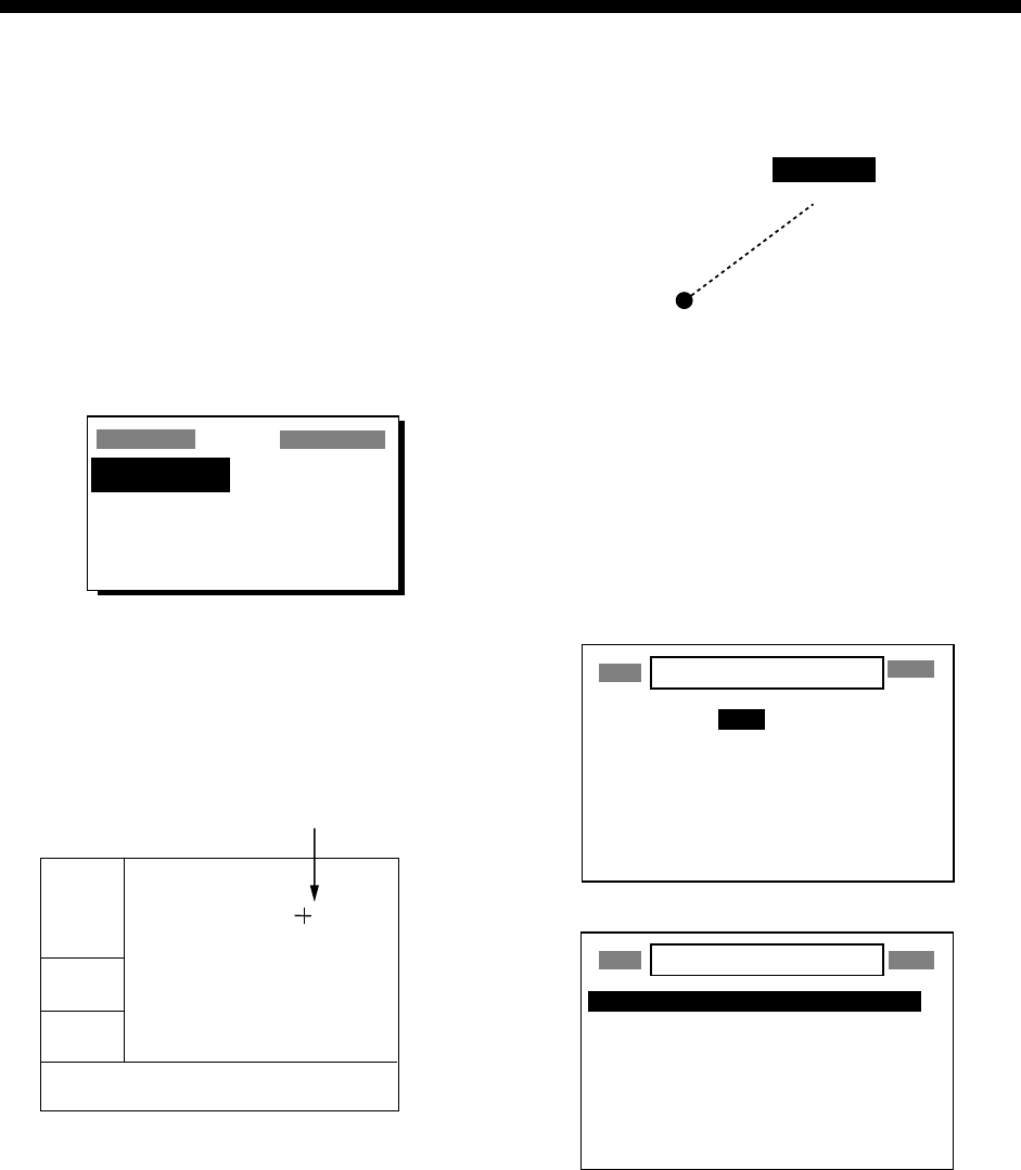
Temporarily deselecting a waypoint in
a route
You can temporarily deselect an unnecessary
waypoint from a route. Using the route
created in the illustration at the top of the next
column as an example, deselect the 2nd
intermediate waypoint.
Intermediate Point 2
(WPT 002)
[ROUTE 01]
KOBE
(Starting point)
Intermediate Point 1
(WPT 001)
Intermediate Point 1
(WPT 003)
OSAKA
(Arrival point)
Sample route
If you reconstruct the route without the 2nd
intermediate point it would look like the
illustration below.
WPT 002
SKIP "002"
WPT 001
KOBE WPT 003
OSAKA
Reconstruction of sample route above without
the 2nd intermediate waypoint
1. Press the [MENU] key once or twice to
display the menu.
2. Choose ROUTES and then press the
[ENT] key.
3. Choose route desired and then press the
[ENT] key.
4. Place the cursor on the waypoint to skip.
5. Press the [ENT] key.
6. Choose “SKIP?” and then press the [ENT]
key. “X” appears to the left of the waypoint
skipped as shown in the illustration below.
ROUTE-01 Exit?
CMNT: KOBE → OSAKA
TOTAL DISTANCE 21.0nm
01. KOBE
x 02. 001
03. OSAKA
04. _ _ _ _ _ _
05. _ _ _ _ _ _
10.2nm 180°
9.8 nm 90°
Skipped
waypoint
Route contents (Route-01)

4. ROUTES
25
7. Press the [MENU] key twice to finish.
To restore a waypoint to a route, choose
“SKPoFF ?”at step 6 in this procedure, press
the [ENT] key and then press the [MENU] key
twice to finish.
Changing route comment (name)
You can change the comment (name) for a
route as below. Up to 16 alphanumeric
characters may be used.
1. Press the [MENU] key or twice to display
the menu.
2. Choose ROUTES and then press the
[ENT] key.
3. Choose route number and then press the
[ENT] key.
4. Choose CMNT and then press the [ENT]
key.
5. Enter comment with the cursor pad and
then press the [ENT] key.
6. Press the [MENU] key twice to finish.
4.3 Erasing Routes
1. Press the [MENU] key or twice to display
the menu.
2. Choose ERASE and then press the [ENT]
key.
3. Choose “ROUTES?” and then press the
[ENT] key.
4. Choose the route you want delete. If you
want to delete all routes, choose “ALL?.”
5. Press the [ENT] key. You are asked if you
are sure to delete the route(s).
ERASE ROUTE 01 ?
ARE YOU SURE?
YES NO
Erase route options
6. Choose YES and then press the [ENT]
key.
7. Press the [MENU] key twice to finish.
4. ROUTES
26
(This page intentionally left blank.)
27
5. DESTINATION
Destination can be set four ways: by cursor,
by waypoint, by route, and by MOB position.
Previous destination is cancelled whenever a
destination is newly set.
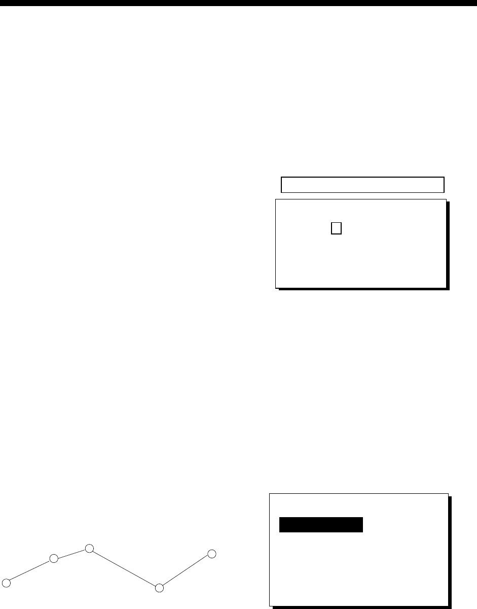
5.1 Setting Destination by
Cursor
1. Press the [GOTO] key to display the
GOTO options window.
GOTO
WPT-LIST?
_ _ _ _ _ _
?
WPT-NEAR? OFF??
ROUTE?
CURSOR? SETUP?
GOTO options
2. Choose “CURSOR?.”
3. Press the [ENT] key. The plotter display
appears, with “?” shown to the right of the
cursor.
2D
[ 40 ]
n
m
72°
54.5
n
m
34°44.000N 135°21.000E
?
Cursor appears with "?".
BRG: +
RNG: +
+GOTO?
Cursor appearance
when setting destination by cursor
4. Use the cursor pad to place the cursor on
the location desired for destination.
5. Press the [ENT] key.
A dashed line connects own ship and the
destination, which is marked with “CURSOR”
and an “X,” as shown in the illustration below.
x
CURSOR
Destination set by cursor
5.2 Setting Destination by
Waypoint
1. Press the [GOTO] key.
2. Choose “WPT-LIST?” or “WPT-NEAR?”.
3. Press the [ENT] key. The SELECT GOTO
WPT list appears.
SELECT GOTO WPT
[NEW?] 001 002
003 004 005
006 007 008
CURSOR KOBE MOB
OSAKA START _ _ _ _ _ _
_ _ _ _ _ _ _ _ _ _ _ _ _ _ _ _ _ _
_ _ _ _ _ _ _ _ _ _ _ _ _ _ _ _ _ _
SELECT GOTO WPT
WPT-LIST
WPT-NEAR
START : 2.97 nm 68°
OSAKA : 1.90 nm 335°
006 : 3.53 nm 15°
005 : 4.79 nm 11°
004 : 4.86 nm 15°
008 : 5.21 nm 345°
CURSOR : 6.41 nm 356°
SELECT GOTO WPT screens
4. Choose a waypoint.
5. Press the [ENT] key.
Own ship’s position becomes the starting
point and a dashed line runs between it and
the waypoint selected, which is shown in
reverse video.

5. DESTINATION
28
5.3 Setting Route as
Destination
1. Press the [GOTO] key.
2. Choose “ROUTE?”.
3. Press the [ENT] key.
SELECT GOTO ROUTE
NO [NEW?]
LOG EMPTY ROUTE
01 017 021
02 OSAKA KOBE
03 EIMI KIMI
04 BOSTON
GOTO ROUTE list
4. Choose a route.
5. Press the [ENT] key. The following
options window appears.
FORWARD?
REVERSE?
Route following direction options
6. Choose “FORWARD?” or “REVERSE?”,
the order in which to traverse the route
waypoints, and then press the [ENT] key.
Intermediate Point 2
(WPT 002)
[ROUTE 01]
KOBE
(Starting point)
Intermediate Point 1
(WPT 001)
Intermediate Point 1
(WPT 003)
OSAKA
(Arrival point)
FORWARD REVERSE
Meaning of forward and reverse
Current position becomes the starting point. A
dashed line runs between the starting point
and all route waypoints. Next destination
waypoint is shown in reverse video.
The destination waypoint is automatically
switched when the boat enters the arrival
alarm range or the boat passes an imaginary
perpendicular line passing through the center
of the destination waypoint. For how to set
the arrival alarm, see paragraph 6.1.
5.4 Setting User Waypoint as
Destination
You may place a desired waypoint in the
GOTO options window and use it to set
destination.
Choosing user waypoint
1. Press the [GOTO] key.
2. Choose “SETUP?” and then press the
[ENT] key.
SELECT USER WPT
[NEW?] 001 002
003 004 005
006 007 008
CURSOR KOBE MOB
OSAKA START _ _ _ _ _ _
_ _ _ _ _ _ _ _ _ _ _ _ _ _ _ _ _ _
_ _ _ _ _ _ _ _ _ _ _ _ _ _ _ _ _ _
SELECT USER WPT list
3. Choose waypoint desired and then press
the [ENT] key. The GOTO window
appears, showing the waypoint selected
as below.
GOTO
WPT-LIST? 001
WPT-NEAR? OFF??
ROUTE?
CURSOR? SETUP?
Location of
user waypoint
(Example: 001)
GOTO options
4. Choose user waypoint and then press the
[ENT] key.
A dashed line connects own ship and the
waypoint selected, which is shown in reverse
video.
5.5 Canceling Destination
You can cancel destination as follows:
1. Press the [GOTO] key.
2. Choose “OFF?”.
3. Press the [ENT] key.
29
6. ALARMS
There are eight alarm conditions which
generate both audio and visual alarms:
Arrival alarm, Anchor watch alarm, XTE
(Cross-Track Error) alarm, Speed alarm,
WAAS/DGPS alarm, Time alarm, Trip alarm
and Odometer alarm.
When an alarm setting is violated, the buzzer
sounds and the name of the offending alarm
and the alarm icon appear on the display.
You can silence the buzzer and remove the
alarm name indication by pressing any key.
The alarm icon remains on the screen until
the reason for the alarm is cleared.
In some instances, multiple alarms may have
been violated. You can see which alarm(s) is
sounding by displaying the message board.
The keying sequence is [MENU] (once or
twice), MESSAGE, [ENT]. The message
board is discussed in paragraph 8.2
“Displaying the Message Board.”
To disable an alarm, choose OFF as its
option, press the [ENT] key and then press
the [MENU] key twice.
2D
[ 40
]
n
m
COG:
82°
SOG:
9.0 k
t
34°44.000N 135°21.000E
Alarm message
!
XTE ALARM!
Alarm
icon
Location of alarm message and alarm icon
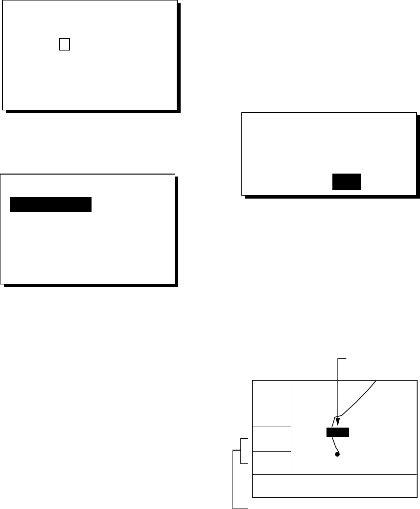
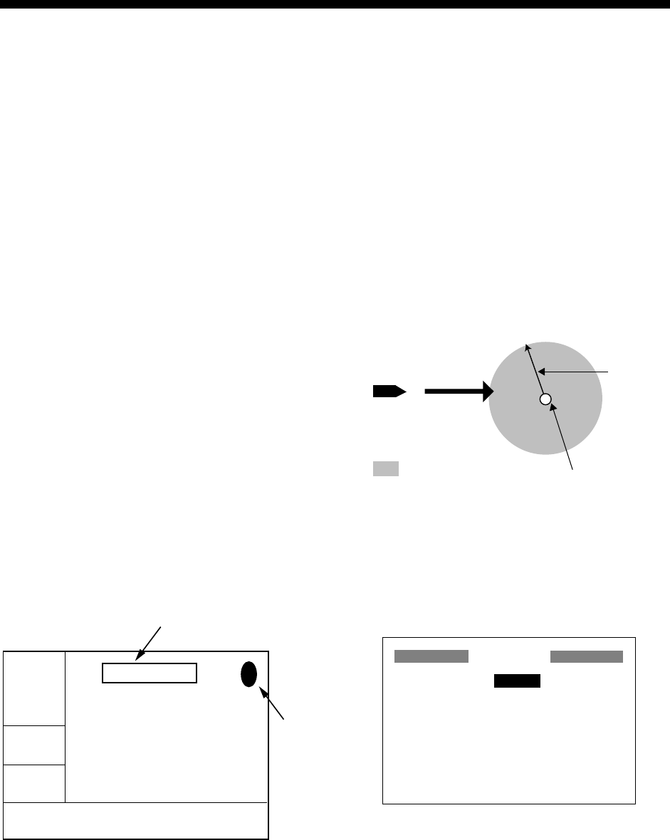
6.1 Arrival Alarm, Anchor
Watch Alarm
You may activate the arrival alarm or the
anchor watch alarm; they cannot be activated
together.
Arrival alarm
The arrival alarm informs you that own ship is
approaching a destination waypoint. The area
that defines an arrival zone is that of a circle
which you approach from the outside of the
circle. The alarm will be released if own ship
enters the circle.
: Alarm released
Own ship's
position
Alarm
setting
Destination
waypoint
How the arrival alarm works
1. Press the [MENU] key once or twice to
open the menu.
2. Choose ALARMS.
3. Press the [ENT] key to show the ALARMS
menu.
ALARMS
BUZZER : LONG
ARV/ANC : ARV 0.30 nm
XTE : OFF 0.50 nm
SPEED : OFF 12.0 kt
WAAS/DGPS : OFF
TIME : OFF 00:00
TRIP : OFF 0 nm
ODOMETER : OFF 0 nm
ALARMS menu
6. ALARMS
30
4. Choose ARV/ANC and then press the
[ENT] key.
OFF
ARV
ANC
Arrival/anchor watch options
5. Choose ARV and then press the [ENT]
key.
6. Press the [ENT] key. Enter the alarm
range (0.0-99.99 nm) with the cursor pad.
7. Press the [ENT] key.
8. Press the [MENU] key twice to finish.
When own ship nears the GOTO waypoint by
the range set here, the buzzer sounds and
the message ARV ALARM! appears.
Anchor watch alarm
The anchor watch alarm sounds to warn you
that own ship is moving when it should be at
rest.
: Alarm released
Own ship's
position
Destination
waypoint
Alarm
setting
How the anchor watch alarm works
Before setting the anchor watch alarm, set
current position as destination waypoint,
referring to paragraph 5.2.
1. Press the [MENU] key once or twice to
open the menu.
2. Choose ALARMS.
3. Press the [ENT] key.
4. Choose ARV/ANC and then press the
[ENT] key.
5. Choose ANC and then press the [ENT]
key.
6. Press the [ENT] key. Enter the alarm
range (0.01-99.99 nm) with the cursor
pad.
7. Press the [ENT] key.
8. Press the [MENU] key twice to finish.
When own ship drifts more than the range set
here, the buzzer sounds and the message
ANC ALARM! and the alarm icon appear.
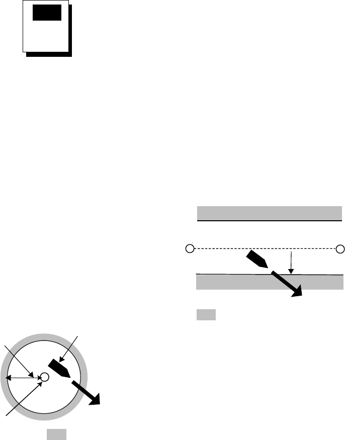
6.2 XTE (Cross Track Error)
Alarm
The XTE alarm warns you when own ship is
off its intended course.
: Alarm released
Destination
waypoint
Own ship's
position
Alarm
setting
How the XTE alarm works
1. Press the [MENU] key once or twice to
open the menu.
2. Choose ALARMS.
3. Press the [ENT] key.
4. Choose XTE and then press the [ENT]
key.
5. Choose ON and then press the [ENT] key.
6. Press the [ENT] key. Enter alarm range
(0.0-99.99 nm) with the cursor pad.
7. Press the [ENT] key.
8. Press the [MENU] key twice to finish.
When own ship strays from the intended track
by the range set here, the buzzer sounds and
message XTE ALARM! and the alarm icon
appear.

6. ALARMS
31
6.3 Speed Alarm
The speed alarm provides visual and aural
alerts when the ship’s speed is higher (or
lower) than the alarm range set.
1. Press the [MENU] key once or twice to
open the menu.
2. Choose ALARMS.
3. Press the [ENT] key.
4. Choose SPEED and then press the [ENT]
key.
5. Choose LOW or HIGH as appropriate and
then press the [ENT] key.
LOW: Alarm sounds when speed is lower
than speed set.
HIGH: Alarm sounds when speed is
higher than speed set.
6. Press the [ENT] key. Enter speed
(0.0-999.9 kt) with the cursor pad.
7. Press the [ENT] key.
8. Press the [MENU] key twice to finish.
When the speed alarm setting is violated, the
buzzer sounds and the message SPD
ALARM! and the alarm icon appear.
6.4 WAAS/DGPS Alarm
This alarm alerts you by aural and visual
alarms when the WAAS/DGPS signal is lost.
Note that ON cannot be selected if “MODE” in
the WAAS/DGPS menu is set to GPS.
1. Press the [MENU] key once or twice to
open the menu.
2. Choose ALARMS.
3. Press the [ENT] key.
4. Choose WAAS/DGPS and then press the
[ENT] key.
5. Choose ON.
6. Press the [ENT] key.
7. Press the [MENU] key twice to finish.
When the DGPS/WAAS signal is lost, the
buzzer sounds and a message (see table
below) and the alarm icon appear. Further,
the default position is shown.
WAAS/DGPS mode and alarm message
MODE on
WAAS/DGPS
menu
Alarm condition, alarm
message
WAAS
Alarms released when
receiver status changes from
W2D or W3D to 2D or 3D.
“WAAS ERROR!” and the
alarm icon appear when this
occurs.
INT BEACON,
EXT BEACON
Alarms released when
receiver status changes from
D2D or D3D to 2D or 3D.
“DGPS ERROR!” and the
alarm icon appear when this
occurs.
AUTO
Alarms released when
receiver status changes from
D2D, D3D, W2D or W3D to
2D or 3D. “WAAS/DGPS
ERROR!” and the alarm icon
appear when this occurs.
6.5 Time Alarm
The time alarm works like an alarm clock,
releasing audio and visual alarms when the
time entered has come.
1. Press the [MENU] key once or twice to
open the menu.
2. Choose ALARMS.
3. Press the [ENT] key.
4. Choose TIME and then press the [ENT]
key.
5. Choose ON and then press the [ENT] key.
6. Press the [ENT] key.
7. Enter time desired with the cursor pad.
8. Press the [ENT] key.
9. Press the [MENU] key twice to finish.
When the time entered has come, the buzzer
sounds and the message TIME ALARM! and
the alarm icon appear.

6. ALARMS
32
6.6 Trip Alarm
This alarm alerts you by aural and visual
alarms when your boat has traveled a
distance greater than the trip alarm distance.
1. Press the [MENU] key once or twice to
open the menu.
2. Choose ALARMS.
3. Press the [ENT] key.
4. Choose TRIP and then press the [ENT]
key.
5. Choose ON and then press the [ENT] key.
6. Press the [ENT] key. Enter distance
desired (001-999 nm) with the cursor pad.
7. Press the [ENT] key.
8. Press the [MENU] key twice to finish.
When the boat has traveled further than the
preset trip distance, the buzzer sounds and
the message TRIP ALARM! and the alarm
icon appear.
6.7 Odometer Alarm
This alarm alerts you by aural and visual
alarms when your boat has traveled the total
distance you set.
1. Press the [MENU] key once or twice to
open the menu.
2. Choose ALARMS.
3. Press the [ENT] key.
4. Choose ODOMETER and then press the
[ENT] key.
5. Choose ON and then press the [ENT] key.
6. Press the [ENT] key. Enter distance
desired (001-999 nm) with the cursor pad.
7. Press the [ENT] key.
8. Press the [MENU] key twice to finish.
When the boat has traveled further than the
preset trip distance, the buzzer sounds and
the message ODOMETER ALARM! and the
alarm icon appear.
6.8 Buzzer Type Selection
The buzzer sounds whenever an alarm
setting is violated. You can choose the type
of buzzer to use as follows:
1. Press the [MENU] key once or twice to
open the menu.
2. Choose ALARMS.
3. Press the [ENT] key.
4. Choose BUZZER and then press the
[ENT] key.
SHORT
LONG
CONSTANT
Buzzer sound options
5. Choose buzzer type desired and then
press the [ENT] key.
SHORT: Two short beeps
LONG: Three long beeps
CONSTANT: Continuous beeps
6. Press the [MENU] key twice to finish.
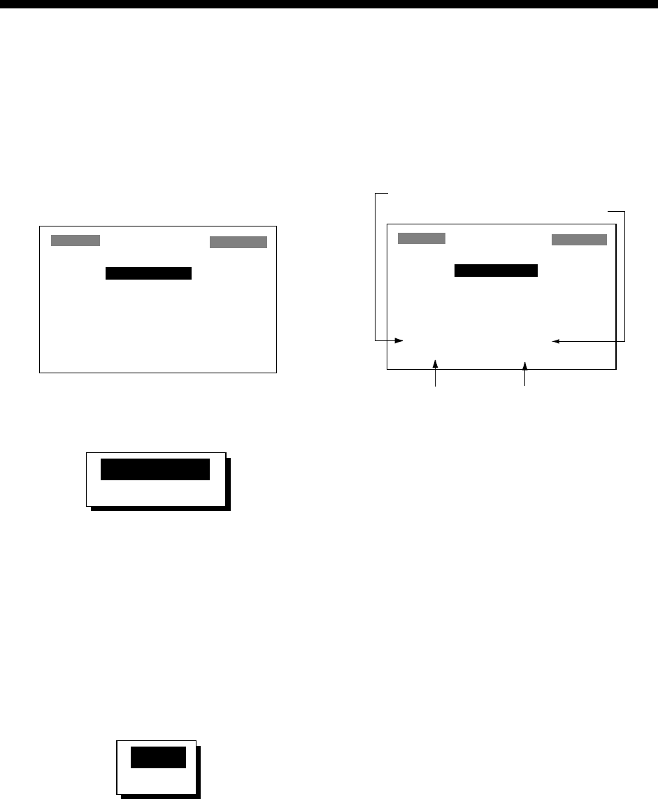
33
7. OTHER FUNCTIONS
7.1 Calculating Range,
Bearing, TTG and ETA
Range and bearing between two
waypoints
1. Press the [MENU] key once or twice to
open the menu.
2. Choose CALCULATE and then press the
[ENT] key.
CALCULATION
MODE: WAYPOINTS
FROM : _ _ _ _ _ _
TO : _ _ _ _ _ _
SPD : AUTO
TTG:
_ _
H
_ _
M ETA:
_ _
:
_ _
RNG:
_
.
_ _
nm BRG:
_ _ _
°
CALCULATION menu
3. The cursor is selecting MODE. Press the
[ENT] key.
WAYPOINTS
ROUTE
Range and bearing calculation options
4. Choose WAYPOINTS and then press the
[ENT] key.
5. Press the [ENT] key.
6. Enter the FROM waypoint and then press
the [ENT] key.
7. Press the [ENT] key, enter the TO
waypoint and then press the [ENT] key.
8. Press the [ENT] key to display the speed
input options.
AUTO
MAN
Speed input options
9. Choose AUTO or MAN and then press the
[ENT] key. AUTO uses ship’s average
speed; MAN is for manual entry of speed.
For AUTO, see the illustration after step
10 for sample range and bearing
calculation. For MAN, go to step 10.
10. Press the [ENT] key. Enter speed with the
cursor pad and then press the [ENT] key.
The illustration below shows what the
display might look like using waypoints
KOBE and OSAKA as the FROM and TO
waypoints, respectively.
CALCULATION
MODE: WAYPOINTS
FROM : KOBE
TO : OSAKA
SPD : AUTO
TTG: 1H39M ETA: 5:57
RNG: 9.06 nm BRG: 80
°
Time-to-Go
Estimated Time of Arrival
Range Bearing
Typical range and bearing calculation
between two waypoints
11. Press the [MENU] key twice to finish.
Range, TTG and ETA between first and
final waypoints of a route
You can easily find the range, TTG and ETA
between the first and final waypoints of a
route as follows:
1. Press the [MENU] key once or twice to
open the menu.
2. Choose CALCULATE and then press the
[ENT] key.
3. Press the [ENT] key.
4. Choose ROUTE and then press the [ENT]
key.
5. Press the [ENT] key.
6. Choose route number from the route list
with the cursor pad.
7. Press the [ENT] key to open the speed
input options window.
8. Choose AUTO or MAN. AUTO uses ship’s
average speed; MAN is for manual entry
of speed.
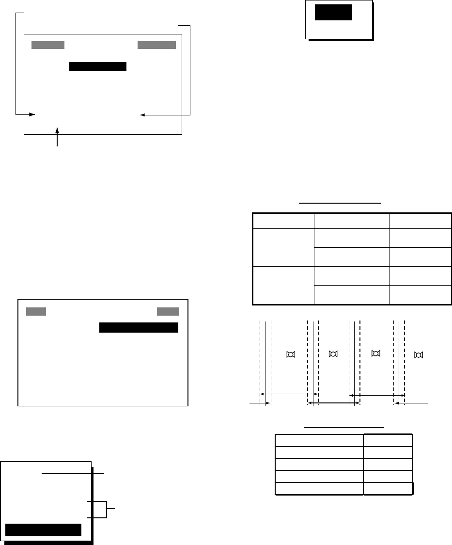
7. OTHER FUNCTIONS
34
9. Press the [ENT] key. If you selected
AUTO no further operation is necessary.
See the illustration below for a calculation
example. For MAN, press the [ENT] key,
enter speed with the cursor pad and then
press the [ENT] key.
The illustration below shows what the
display might look like using Route-01 as
an example.
CALCULATION
MODE: ROUTE
NO. : 01 (WPTS: 4)
KOBE → OSAKA
SPD : AUTO
TTG: 1H55M ETA: 07:17
RNG: 11.25 nm BRG: _ _ _°
Time-to-Go
Estimated Time of Arrival
Range
Typical TTG, ETA, range calculation for route
10. Press the [MENU] key twice to finish.
7.2 WAAS Setup
1. Press the [MENU] key once or twice to
open the menu.
2. Choose WAAS/DGPS and then press the
[ENT] key.
WAAS/DGPS SETUP
MODE : AUTO
WAAS SEARCH: AUTO 120
CORRECTIONS DATA SET: 02
DGPS STATION: AUTO
RATE : 200BPS
FREQ : 310.0 kHz
STATION
: GOOD DATA: GOOD
SIG.S: 55.2 dB SNR: 22.0dB
WAAS/DGPS SETUP menu
3. The cursor is selecting MODE; press the
[ENT] key.
GPS
WAAS
INT BEACON
EXT BEACON
AUTO
DGPS position fixing
GPS position fixing
WAAS/DGPS mode options
4. Choose appropriate mode referring to the
descriptions below. Press the [ENT] key.
WAAS: Position fix by WAAS
AUTO: Position fix in priority order of
DGPS, WAAS, and GPS.
5. Press the [ENT] key.
6. WAAS SEARCH is selected; press the
[ENT] key.
AUTO
MANUAL
WAAS search options
7. Choose AUTO for automatic search or
MANUAL for manual search and then
press the [ENT] key. For MANUAL, press
the [ENT] key, enter appropriate WAAS
satellite number, referring to the
illustration below and then press the
[ENT] key.
AUTO mode and GEO satellite
(as of April 2002)
Provider GEO Satellite Longitude
POR (134) 178°E
WAAS AOR-W (122) 54°W
AOR-E (120) 15.5°W
EGNOS IOR (131) 64.5°E
122
AOR-W
54°W
120
AOR-E
15.5°W
131
IOR
64.5°W
134
POR
178°E
118°W 34.75°W 24.5°E 121.25°E
2°2°2°2°
Longitude Range Satellite
120.25
°
E to 117
°
W 134
119
°
W to 33.75
°
W 122
35.75
°
W to 25.5
°
E 120
23.5
°
E to 122.25
°
E 131
One-degree threshold
GEO satellite and coverage area

7. OTHER FUNCTIONS
35
8. The cursor is now selecting
CORRECTIONS DATA SET; press the
[ENT] key.
CORRECTIONS DATA SET determines
how to use the WAAS signal, currently in
the test mode. Use the default setting
(02) until the WAAS system becomes
operational, then change the setting to
“00”.
9. Press the [ENT] key.
10. Press the [MENU] key twice to close the
menu.
7.3 DGPS setup
1. Press the [MENU] key once or twice to
open the menu.
2. Choose WAAS/DGPS.
WAAS/DGPS SETUP
MODE : GPS
WAAS SEARCH: AUTO 120
CORRECTIONS DATA SET: 02
DGPS STATION: AUTO
RATE : 200BPS
FREQ : 310.0 kHz
STATION
: ---* DATA: ---*
SIG.S: 00.0 dB * SNR: 02.0dB*
* = See note below.
WAAS/DGPS SETUP menu
DGPS Data
STATION: Shows GOOD or NG.
DATA: Shows GOOD or NG.
SIG. S: Signal Strength. A figure
between 0 and 99 is shown. The higher
the figure the stronger the beacon signal.
SNR: Signal to Noise Ratio. A figure
between 1and 22 is shown. A figure under
18 means position will be inaccurate.
When your boat is in the service area of a
beacon station, SNR should be 21 or 22.
If not, the problem may lie with the
grounding, radar interference or generator
noise on own boat.
3. Press the [ENT] key to show the mode
options window.
4. Choose one of the following and then
press the [ENT] key.
INT BEACON: Position fix by internal
DGPS beacon receiver (GP-37 only,
cannot be selected on GP-32)
EXT BEACON: Position fix by external
DGPS beacon receiver (GP-32)
AUTO: Position fix by DGPS, WAAS and
GPS, in order of availability.
Note: When connecting FURUNO
external DGPS beacon receiver GR-80 to
the GP-32, turn the GR-80’s remote
function on to set up the beacon receiver
with data set on the GP-32.
5. DGPS STATION is selected; press the
[ENT] key.
6. Choose DGPS beacon station selection
method: AUTO, MANUAL or LIST.
AUTO: Automatically searches for best of
five nearest DGPS beacon station. It first
searches DGPS beacon stations from
closest to furthest. If unsuccessful it
searches stations by signal strength. This
procedure is repeated until a suitable
station is found.
MANUAL: Manually enter DGPS beacon
station specifications at RATE and FREQ,
referring to a DGPS beacon station list.
LIST: Lists five of the closest DGPS
beacon stations, including
user-programmed stations.
7. Press the [ENT] key. If you selected
AUTO no further operation is required; go
to step 8. If you selected MANUAL or LIST,
do one of the following and then go to
step 8.
MANUAL
a) The cursor is selecting RATE. Press
the [ENT] key.
b) Choose the transmission rate of the
DGPS beacon station to be used,
among 50, 100 or 200 bps. Press the
[ENT] key.
c) The cursor is selecting FREQ. Press
the [ENT] key.
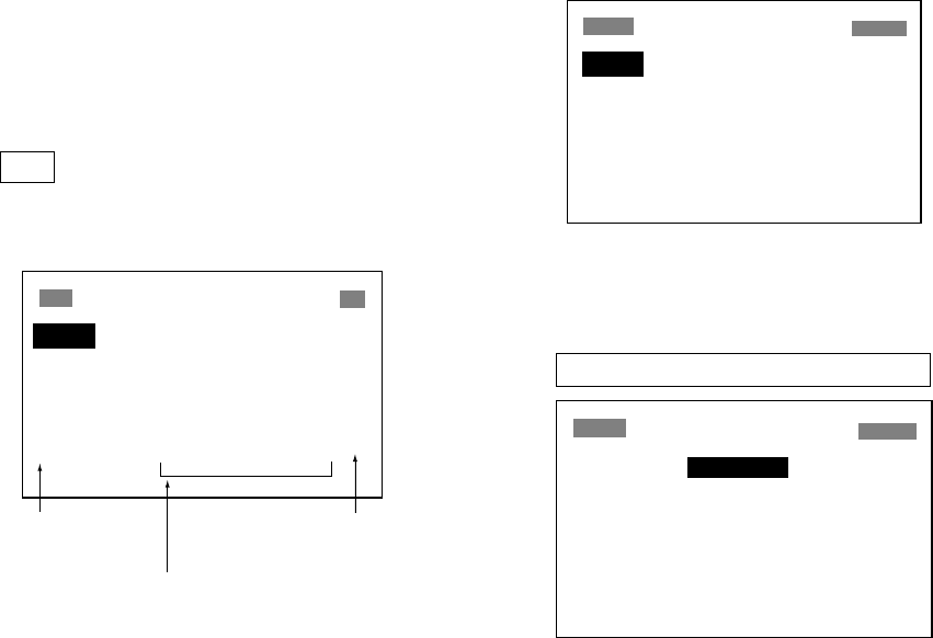
7. OTHER FUNCTIONS
36
d) Use the cursor pad to enter the
transmission frequency of the DGPS
beacon station to be used and then
press the [ENT] key.
LIST
a) The following display appears after
pressing the [ENT] key at step 6.
STATION (NEAREST)
"*" denotes
user channel.
[EXIT] [USER]
310.0 29.1 nm 92°
287.0 56.7 nm 134°
292.0 160 nm 320°
321.0 234 nm 134°
302.0 426 nm 121° *
Tx frequency of
beacon station
Range (ref. only) and bearing from
ship to beacon station
DGPS beacon station list
b) Use the cursor pad to choose station
desired.
c) Press the [ENT] key.
8. Press the [MENU] key twice to finish.
Programming DGPS user channels
(stations)
The user may program 20 DGPS beacon
stations from which to use in DGPS beacon
station selection. Whenever a new station is
constructed you can add it to the list.
1. Press the [MENU] key twice to open the
menu.
2. Choose DGPS/WAAS and then press the
[ENT] key.
3. Choose DGPS STATION and then press
the [ENT] key.
4. Choose LIST and then press the [ENT]
key.
5. Choose USER and then press the [ENT]
key.
STATION (USER)
[EXIT] [NEW?] [CLR?]
01
_ _ _ _ _ _ _ _ _ _ _ _ _ _ _ _ _
02
_ _ _ _ _ _ _ _ _ _ _ _ _ _ _ _ _
03
_ _ _ _ _ _ _ _ _ _ _ _ _ _ _ _ _
04
_ _ _ _ _ _ _ _ _ _ _ _ _ _ _ _ _
05
_ _ _ _ _ _ _ _ _ _ _ _ _ _ _ _ _
06
_ _ _ _ _ _ _ _ _ _ _ _ _ _ _ _ _
DGPS STATION (USER) list
6. Choose “NEW?” and then press the [ENT]
key.
STATION (USER)
NEW USER CHANNEL
FREQ : 310.0kHz
RATE : 200BPS
LAT : 37°59'N
LON : 123°00'W
EXIT? SAVE?
NEW USER CHANNEL (DGPS) set up menu
7. Press the [ENT] key, enter frequency of
the station, and then press the [ENT] key.
8. Press the [ENT] key, enter baud rate of
the station, and then press the [ENT] key.
9. Press the [ENT] key, enter latitude of the
station, and then press the [ENT] key.
10 Press the [ENT] key, enter longitude of
the station, and then press the [ENT] key.
11. Choose “SAVE?” and then press the
[ENT] key.
12. Press the [MENU] key twice to finish.
Editing DGPS user channels
1. Press the [MENU] key twice to open the
menu.
2. Choose WAAS/DGPS and then press the
[ENT] key.
3. Choose DGPS STATION and then press
the [ENT] key.
4. Choose LIST and then press the [ENT]
key.
5. Choose USER and then press the [ENT]
key.
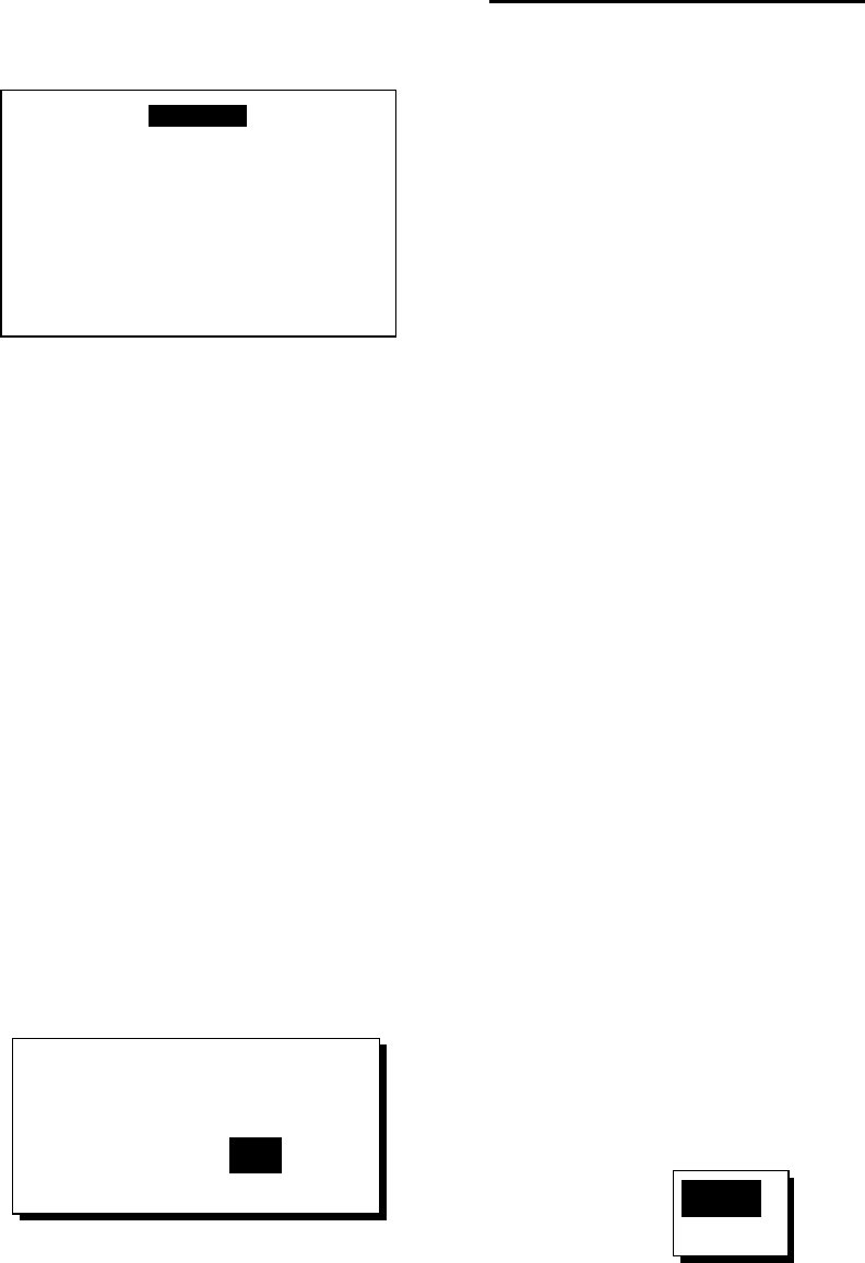
7. OTHER FUNCTIONS
37
6. Choose a station from the list and then
press the [ENT] key. The display looks
something like the one below.
FREQ : 310.0kHz
RATE : 200BPS
LAT : 37°59'N
LON : 123°00'W
EXIT? SAVE? ERASE?
Screen for entering DGPS station data
7. Choose item, press the [ENT] key, edit
data, and then press the [ENT] key.
8. Choose “SAVE?” and then press the
[ENT] key.
9. Press the [MENU] key twice to finish.
Erasing all user channels
1. Press the [MENU] key twice to open the
menu.
2. Choose DGPS/WAAS and then press the
[ENT] key.
3. Choose DGPS STATION and then press
the [ENT] key.
4. Choose LIST and then press the [ENT]
key.
5. Choose USER and then press the [ENT]
key.
6. Choose “CLR?” and then press the [ENT]
key. The following message appears.
ERASE ALL ?
ARE YOU SURE ?
YES NO
DGPS channel erase options
7. Press ◄ to choose YES and then press
the [ENT] key.
8. Press the [MENU] key twice to finish.
Erasing individual user channels
1. Press the [MENU] key twice to open the
menu.
2. Choose DGPS/WAAS and then press the
[ENT] key.
3. Choose DGPS STATION and then press
the [ENT] key.
4. Choose LIST and then press the [ENT]
key.
5. Choose USER and then press the [ENT]
key.
6. Choose a channel from the list and then
press the [ENT] key.
7. Choose “ERASE?”.
8. Choose YES and then press the [ENT]
key.
9. Press the [MENU] key twice to finish.
7.4 Bearing Reference
Ship's course and bearing to a waypoint may
be displayed in true or magnetic bearing.
Magnetic bearing is true bearing plus (or
minus) earth’s magnetic deviation. Use the
bearing reference in accordance with the
compass interfaced: magnetic for magnetic
compass, true for gyrocompass. The default
setting displays magnetic bearings.
1. Press the [MENU] key once or twice to
open the menu.
2. Choose PLOTTER.
3. Press the [ENT] key.
4. Choose BRG. REF.
5. Press the [ENT] key.
MAG
TRUE
Bearing reference options
6. Choose MAG or TRUE as appropriate.
7. Press the [ENT] key.
8. Press the [MENU] key twice to finish.

7. OTHER FUNCTIONS
38
7.5 Magnetic Variation
The location of the magnetic north pole is
different from the geographical north pole.
This causes a difference between the true
and magnetic north direction. This difference
is called magnetic variation, and varies with
respect to the observation point on earth.
Your unit is preprogrammed with all the
earth's magnetic variation. However, you may
wish to enter variation manually to refine
accuracy. Set “BRG REF” on the PLOTTER
is set to “MAG” to use magnetic variation.
1. Press the [MENU] key once or twice to
open the menu.
2. Choose PLOTTER and then press the
[ENT] key.
3. Choose MAG. VAR.
4. Press the [ENT] key.
5. Choose AUTO or MAN as appropriate
and then press the [ENT] key. For
automatic magnetic variation, current
magnetic variation appears to the right of
AUTO.
6. If you selected AUTO, no further
operation is necessary; go to step 7. For
MAN, press the [ENT] key and enter
magnetic variation as follows:
a) If necessary, change coordinate from
east to west or vice versa by pressing
▲ or ▼.
b) Press ► to shift cursor, use ▲ or ▼ to
set value, referring to a nautical chart.
c) Press the [ENT] key.
7. Press the [MENU] key twice to finish.
7.6 Geodetic Chart System
Your unit is preprogrammed to recognize
most of the major chart systems of the world.
Although the WGS-84 system, the GPS
standard, is now widely used other categories
of charts still exist. Choose the chart system
used, not the area where your boat is sailing.
The default chart system is WGS-84.
1. Press the [MENU] key once or twice to
open the menu.
2. Choose SYS SETUP and then press the
[ENT] key.
SYSTEM SETUP
LANGUAGE : ENGLISH
DATUM : WGS84
UNITS : nm, kt
TIME DIFF : +00 : 00
TIME DISP : 24HOUR
TEST?
SIMULATOR?
EXCHANGE BATTERY?
SYSTEM SETUP menu
3. Choose DATUM and then press the [ENT]
key.
4. Choose WGS84 (GPS standard), WGS72
or OTHER as appropriate and then press
the [ENT] key.
5. If you selected WGS84 or WGS72, go to
step 6. For OTHER, do the following:
a) Press the [ENT] key.
b) Use the cursor pad to enter chart
number, referring to the geodetic chart
list on page AP-3.
c) Press the [ENT] key.
6. Press the [MENU] key twice to finish.
7.7 Units of Measurement
Distance/speed can be displayed in nautical
miles/knots, kilometers/kilometers per hour,
or statute miles/miles per hour.
1. Press the [MENU] key once or twice to
open the menu.
2. Choose SYS SETUP and then press the
[ENT] key.
3. Choose UNITS.
4. Press the [ENT] key.
5. Choose combination desired; nm, kt; km,
km/h; sm, mph.
6. Press the [ENT] key.
7. Press the [MENU] key twice to finish.

7. OTHER FUNCTIONS
39
7.8 Position Display Format
Position may shown in latitude and longitude
or TDs (Loran C or Decca) as follows. Decca
and Loran C chain data is preprogrammed.
1. Press the [MENU] key once or twice to
open the menu.
2. Choose TD SETUP and then press the
[ENT] key.
TD SETUP
DISPLAY : XX.XXX'
LORAN C: 7980: 23-43
∆TD1 : +00 . 0
∆TD2 : +00 . 0
DECCA : 25: G-P
∆TD1 : +00 . 0
∆TD2 : +00 . 0
TD SETUP menu
3. The cursor is on the first line. Press the
[ENT] key.
XX.XXX'
XX'XX.X"
LC TD
DE TD
Position display options
4. Choose desired position format.
XX.XXX’: Shows L/L position with no
seconds.
XX’XX.X’: Displays L/L position with
seconds.
LC TD: Loran C TDs
DE TE: Decca TDs
5. Press the [ENT] key. If you selected a
latitude and longitude format, go to step 7.
6. For Loran C or Decca, do one of the
following and then go to step 7.
For Loran C TD:
a) The cursor is on LORAN C. Press the
[ENT] key.
b) Use the cursor pad to choose
appropriate GRI code and secondary
codes, referring to the Loran C chain
list on page AP-4.
c) Press the [ENT] key.
d) If necessary enter TD offsets at ∆TD1
and ∆TD2 to refine position accuracy.
For Decca TD:
a) Choose DECCA and then press the
[ENT] key.
b) Use the cursor pad to choose
appropriate Decca chain number and
lane pair (R, Red, G, Green, P, Purple),
referring to the Decca chain list on
page AP-5.
c) Press the [ENT] key.
d) If necessary enter TD offsets at ∆TD1
and ∆TD2 to refine position accuracy.
7. Press the [MENU] key twice to finish.
7.9 Time Difference (using
local time), Time Format
GPS uses UTC time. If you would rather use
local time, enter the time difference (range:
-13:30 to +13:30) between it and UTC time.
You may display the time in 12 or 24 hour
format.
1. Press the [MENU] key once or twice to
open the menu.
2. Choose SYS SETUP and then press the
[ENT] key.
3. Press ▼ to choose TIME DIFF and then
press the [ENT] key.
4. Press ▲ or ▼ to display “+” or “-“ as
appropriate.
5. Enter time difference with the cursor pad.
6. Press the [ENT] key.
7. The cursor is selecting TIME DISP. Press
the [ENT] key.
8. Choose 12 HOUR or 24 HOUR as
appropriate and then press the [ENT] key.
9. Press the [MENU] key twice to finish.
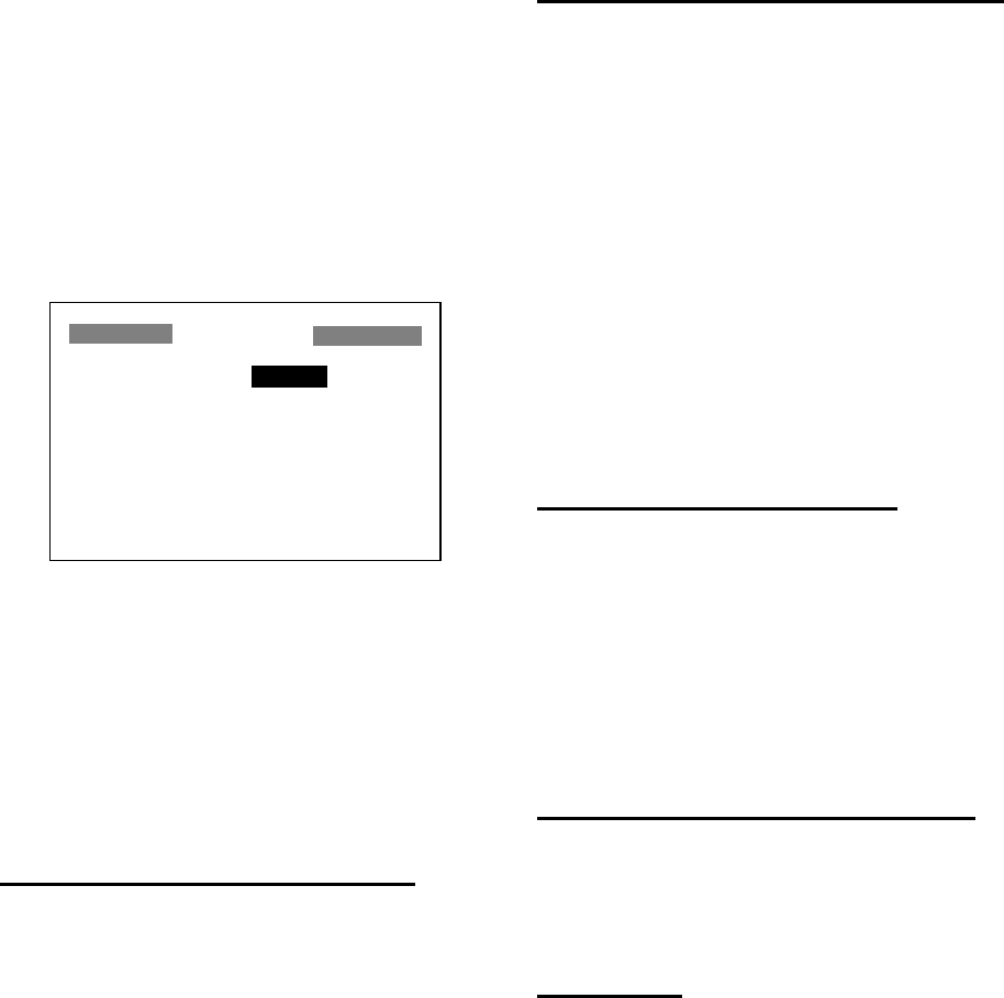
7. OTHER FUNCTIONS
40
7.10 GPS Setup
The GPS SETUP menu smoothes position
and course, averages speed, applies position
offset, and deactivates unhealthy satellites.
1. Press the [MENU] key once or twice to
open the menu.
2. Choose GPS SETUP and then press the
[ENT] key.
GPS SETUP
SMOOTH POS : 0SEC
SMOOTH S/C : 5SEC
AVR. SPEED : 60SEC
LAT OFFSET : 0.000'N
LON OFFSET : 0.000'E
DISABLE SV : _ _ _ _ _ _
FIX MODE : 2/3D
GPS SETUP menu
3. Choose item and then press the [ENT]
key.
4. Change setting with the cursor pad and
then press the [ENT] key.
5. Press the [MENU] key twice to finish.
GPS SETUP menu description
SMOOTH POS (Smoothing position)
When the DOP (Dilution of Precision, the
index for position-fixing accuracy) or receiving
condition is unfavorable, the GPS fix may
change greatly, even if the vessel is dead in
water. This change can be reduced by
smoothing the raw GPS fixes. The setting
range is from 0 (no smoothing) to 999
seconds. The higher the setting the more
smoothed the raw data, however too high a
setting slows response time to change in
latitude and longitude. This is especially
noticeable at high ship’s speeds. “0” is the
normal setting; increase the setting if the
GPS fix changes greatly.
SMOOTH S/C (Smoothing speed/course)
During position fixing, ship’s velocity (speed
and course) is directly measured by receiving
GPS satellite signals. The raw velocity data
may changes randomly depending on
receiving conditions and other factors. You
can reduce this random variation by
increasing the smoothing. Like with latitude
and longitude smoothing, the higher the
speed and course smoothing the more
smoothed the raw data. If the setting is too
high, however, the response to speed and
course change slows. The setting range is
from 0 (no smoothing) to 9999 seconds.
AVR. SPEED (Speed averaging)
Calculation of ETA and TTG, etc. is based on
average ship's speed over a given period. If
the period is too long or too short, calculation
error will result. Change this setting if
calculation error occurs. The default setting is
60 seconds. The setting range is from 0 (no
averaging) to 9999 seconds.
LAT/LON OFFSET (L/L position offset)
You may apply an offset to latitude and
longitude position generated by the GPS
receiver, to increase position accuracy.
DISABLE SV
Every GPS satellite is broadcasting abnormal
satellite number(s) in its Almanac, which
contains general orbital data about all GPS
satellites. Using this information, the GPS
receiver automatically eliminates any
malfunctioning satellite from the GPS satellite
schedule. However, the Almanac sometimes
may not contain this information. You can
disable an inoperative satellite manually.
Enter satellite number in two digits and then
press the [ENT] key. To restore a satellite
enter “00”.
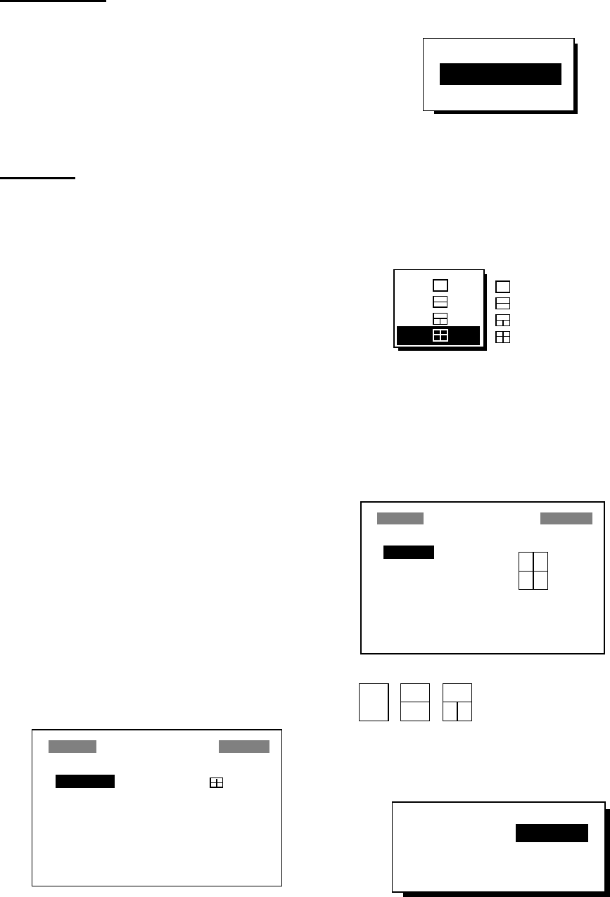
7. OTHER FUNCTIONS
41
DISABLE GEO
Like GPS satellites, the GPS receiver
automatically eliminates any malfunctioning
WAAS satellite. To disable a WAAS satellite
manually, enter three-digit satellite number
with the cursor pad and then press the [ENT]
key. To restore a satellite, enter “000”.
FIX MODE
Chooses position fixing method; 2D or 2/3D.
2D requires three satellites in view of the
GPS receiver; 2/3D requires three or four
satellites in view of the GPS receiver,
whichever is available. When the 2D mode is
selected, enter the antenna height above the
waterline, to obtain accurate position data.
The default setting is 5 m.
7.11 User Display Setup
The user displays, which appear when the
[DISP] key is pressed several times, provide
user-customized digital data and a
speedometer.
Digital data
The user may choose 1-4 items of navigation
data to display on the digital display.
1. Press the [MENU] key once or twice to
open the menu.
2. Choose USER DISP and then press the
[ENT] key.
USER DISPLAY
1: DIGITAL
2: SPEEDOMETER
USER DISPLAY menu
3. Choose 1 or 2 and then press the [ENT]
key.
OFF
DIGITAL
SPEEDOMETER
User display type options
4. Choose DIGITAL and then press the
[ENT] key.
5. The cursor is selecting the square at the
right side of the screen. Press the [ENT]
key.
: 1 indication
: 2 indications
: 3 indications
: 4 indications
User display screen division options
6. Choose the screen division desired, that
is, the number of data to display, and then
press the [ENT] key. The display now
looks something like the one shown
below.
USER DISPLAY
A: POWER
B: TRIP
C: SOG
D: COG
A
A
B
C
D
A
B C
*
* = Changes according to selection at step 6.
A
B
USER DISPLAY menu,
default digital display settings
7. “A” is selected. Press the [ENT] key.
NONE ODO TRIP
TIME POSN POWER
SOG COG WPT
XTE TTG ETA
Digital data options
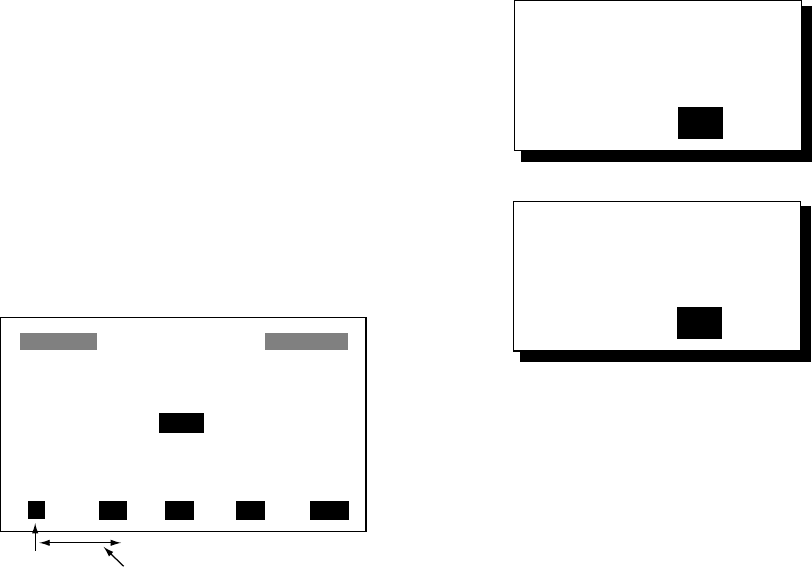
7. OTHER FUNCTIONS
42
8. Use the cursor pad to choose data
desired and then press the [ENT] key.
NONE: No display
ODO: Odometer distance
TRIP: Trip distance
TIME: Time and date
POSN: Position
POWER: Power source voltage
SOG: Speed over ground
COG: Course over ground
WPT: Rng and brg to waypoint
XTE: Cross-track error
TTG: Time to go (to destination)
ETA: Estimated time of arrival
(at destination)
9. Control returns to the User display setup,
with “B” selected. Depending on the
selection made at step 5, set other
indications similar to how you did with “A”.
10. Press the [MENU] key twice to finish.
Speedometer display
1. Press the [MENU] key once or twice to
open the menu.
2. Choose USER DISP and then press the
[ENT] key.
3. Choose 1 or 2 and then press the [ENT]
key.
4. Choose SPEEDOMETER and then press
the [ENT] key.
START FROM: + 0
INTERVAL : 10
SPEEDOMETER
010203040
Start point Interval
Speedometer menu
5. The cursor is selecting START FROM.
Press the [ENT] key.
6. Enter starting speed: Use ◄ or ► to
select location and ▲ or ▼ to enter value
and switch from plus to minus and vice
versa. The setting range is -99 to +99.
7. Press the [ENT] key, and the cursor shifts
to INTERVAL.
8. Press the [ENT] key.
9. Enter scale interval: Use ◄ or ► to
choose location and ▲ or ▼ to enter
value. The setting range is 1 to 99.
10. Press the [ENT] key.
11. Press the [MENU] key twice to close the
menu.
7.12 Resetting Trip and
Odometer Distances
1. Press the [MENU] key once or twice to
open the menu.
2. Choose ERASE and then press the [ENT]
key.
3. Choose “RESET TRIP?” (or “RESET
ODO?”) and then press the [ENT] key.
One of following displays appears.
RESET
TRIP METER?
ARE YOU SURE?
YES NO
RESET
ODOMETER?
ARE YOU SURE?
YES NO
Reset trip meter, odometer options
4. Press ◄ to choose YES and then press
the [ENT] key to reset distance to zero.
5. Press the [MENU] key twice to finish.

7. OTHER FUNCTIONS
43
7.13 Uploading, Downloading
Waypoint, Route Data
Waypoint and route data may be downloaded
to a PC or uploaded from a PC to your unit.
Wiring
Your equipment provides a wiring diagram
which shows how to connect to a PC using a
DSUB 9-pin connector (EIA-574). You may
display it as follows.
1. Press the [MENU] key once or twice to
open the menu.
2. Choose I/O SETUP and then press the
[ENT] key.
3. Choose WIRING INFO and then press the
[ENT] key to display the wiring diagram.
BLUE
GREEN
RED
BLACK
1 TD-H WHITE
2 TD-C/SG
3 SD
4 RD
5 +
6 -
7 FG - +
YELLOW
5 GND
2 RXD
3 TXD
4 DTR
6 DSR
7 RTS
8 CTS
WIRING INFO
PC/AT DSUB-9
GP-32/37 12/24VDC
Wiring diagram, using
DSUB 9-pin connector
Note: A DSUB 25-pin (EIA-232) may also be
used to make the connection. In this case the
wiring diagram is as follows.
BLUE
GREEN
RED
BLACK
1 TD-H
2 TD-C/SG
3 SD
4 RD
5 +
6 -
7 FG - +
YELLOW
7 GND
3 RXD
2 TXD
4 RTS
5 CTS
6 DSR
20 DTR
WHITE
Wiring diagram, using
DSUB 25-pin connector
Setting for communication software on
PC
Baud Rate: 4800 bps
Character Length: 8 bit
Stop Bit: 1 bit
Parity: None
X Control: XON/OFF
Downloading/Uploading between PC
and GP-37/GP-32
Waypoint data and route data can be
downloaded/uploaded between a personal
computer and the GP-37/GP-32.
Note 1: There are two kinds of data for route
data: route data and route comment data.
Note 2: No position fix is available during
uploading or downloading.
Downloading data to a PC
1. Press the [MENU] key once or twice to
open the menu, choose I/O SETUP and
then press the [ENT] key.
I/O SETUP
DATA1 : NMEA-REM1
DATA2 : NMEA-REM
NMEA VER : VER2.0
SAVE WPT/RTE → PC?
LOAD WPT/RTE ← PC?
LOAD WPT← YEOMAN?
WIRING INFO?
I/O SETUP menu
2. Choose SAVE WPT/RTE → PC?.
3. Press the [ENT] key.
SAVE WPT/RTE
ALL WPTS/ROUTES
WILL BE SAVED TO PC.
SET PC PORT TO 4800
8 BIT, P-N, S1, XON/OFF.
CONTINUE?
SAVE WP/RTE display
4. Press the [ENT] key.
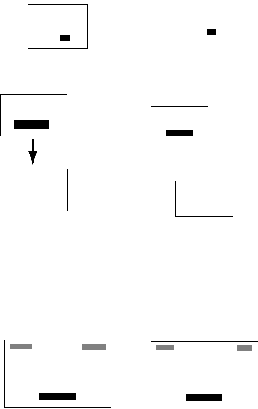
7. OTHER FUNCTIONS
44
SAVING START?
(PC READY?)
ARE YOU SURE?
YES NO
SAVING START? prompt
5. Set up the computer to receive data.
6. Press ◄ to choose YES and then press
the [ENT] key to download.
SAVING
COMPLETED
HIT ANY KEY.
WPTS & ROUTES
SAVING ...
CANCEL?
Data is being
saved. To can-
cel, press the
[ENT] key.
Saving is
completed.
Hit any key
to escape.
Downloading sequence
7. Press any key to escape.
Uploading data from a PC
Note that all waypoint and route data stored
in the GP-37/GP-32 will be deleted when data
is uploaded.
1. Press the [MENU] key once or twice to
open the menu, choose I/O SETUP and
then press the [ENT] key.
2. Choose LOAD WPT/RTE ← PC?.
3. Press the [ENT] key.
LOAD WPT/RTE
LOADING ERASES CUR-
RENT WPT/RTE DATA.
SET PC PORT TO 4800
8 BIT, P-N, S1, XON/OFF.
CONTINUE?
LOAD WP/RTE display
4. Press the [ENT] key.
LOADING START?
(PC READY?)
ARE YOU SURE?
YES NO
LOADING START? prompt
5. Set up the computer to output data.
6. Press ◄ to choose YES and then press
the [ENT] key to upload.
Note: The waypoint and route data are
deleted when the [ENT] key is pressed.
WPTS & ROUTES
LOADING....
CANCEL?
Now loading
data
To cancel, press
[ENT] key.
Message when data is being loaded
7. When the loading is completed, the
following message appears.
LOADING
COMPLETED.
HIT ANY KEY.
Message when data is loaded successfully
8. Press any key to escape.
Loading data from a YEOMAN
Waypoint data from a YEOMAN has the
same format as does the NMEA 0183 data
sentence WPL.
1. Press the [MENU] key twice, choose I/O
SETUP and then press the [ENT] key.
2. Choose LOAD WPT ← YEOMAN?.
3. Press the [ENT] key.
LOAD YEOMAN WPT
LOADING YEOMAN WPT
DATA.
CONTINUE?
LOAD YEOMAN WP display
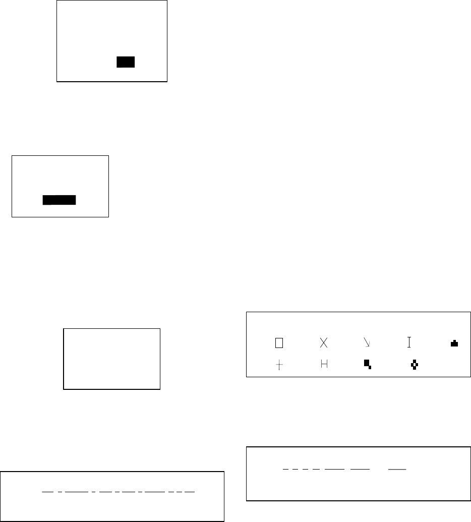
7. OTHER FUNCTIONS
45
4. Press the [ENT] key.
LOADING START?
(YEOMAN READY?)
ARE YOU SURE?
YES NO
LOADING START? prompt
5. Set up the YEOMAN to output data.
6. Press ◄ to choose YES and then press
the [ENT] key to load data.
WAYPOINTS
LOADING....
END?
Now loading
data
To quit loading,
press the [ENT] key.
Message when waypoints are being loaded
7. Data is loaded to empty location and the
buzzer sounds twice to signify successful
loading. If there is not enough memory
free to store the waypoints, the message
below appears.
WAYPOINTS FULL
FULLNOT LOADING
HIT ANY KEY.
Message when waypoints
could not be loaded
Waypoint data format
$PFEC, GPwpl, llll.lll, a, yyyyy.yyy, a, c----c, c, c----c, a, hhmmss, xx, xx, xxxx <CR><LF>
1 2 3 4 5 6 7 8 9 10 11 12
Waypoint data format
1: Waypoint latitude
2: N/S
3: Waypoint longitude
4: E/W
5: Waypoint name (Number of characters is
fixed to 6 and space code is placed when
the number of characters are less than
6.)
6: Waypoint color (This field is always kept
NULL.)
7: Waypoint comment (2 byte for mark code
+ 16 characters of comment.)
1st byte of mark code: Fixed to '@'.
2nd byte of mark code: Internal mark
code + 'a' (0 x 61). See Note 1 on the
next page.
Number of characters for comment is
less than 16 (variable length). See Note 2
on the next page.
8: Flag making waypoint. Always set to “A”.
“A”: Displayed
”V”: Not displayed
9: UTC (Always NULL)
10: Day (Always NULL)
11: Month (Always NULL)
12: Year (Always NULL)
Note 1: Internal mark code is 0 x 10 through
0 x 18. 0 x 71 through 0 x 79 are always
placed at 2nd byte of mark code.
Note 2: Following characters can be used for
comments:
_ABCDEFGHIJKLMNOPQRSTUVWXYZ0123456789&()+-/=?}
0x10: 0x11: 0x12: 0x13: 0x14:
0x15: 0x16: 0x17: 0x18:
(q) (r) (s) (t) (u)
(v) (w) (x) (y)
Characters available for comments
Route data format
$GPRTE, x, x, a, cc, c----c, c----c, ... , c----c <CR><LF>
1 2 3 4 5 6 12
Route data format
1: Number of sentences required for one
complete route data (1 to 4). See Note.
2: Number of sentences currently used (1 to
4)
3: Message mode (Always set to C).
4: Route No. (01 to 51 (51 is LOG route, 2
digits required)
5 through 12: Waypoint name (Max. 8
names, length of each
waypoint name is fixed to 7
byte)
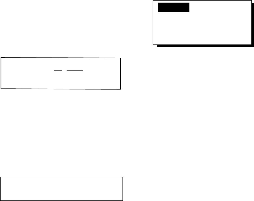
7. OTHER FUNCTIONS
46
1st byte: Skip code '-' (Hyphen) = Skip
ON, Space code = Skip OFF
After 2nd byte: Waypoint name (fixed to
6 bytes)
Note: A route can contain max. 30 waypoints
and GPRTE sentence for one route data may
exceed 80 byte limitation. In this case, route
data is divided into several GPRTE
sentences (Max. 4 sentences). This value
shows the number of sentences route data
has been divided.
Route comment data format
$PFEC, GPrtc, xx, c----c <CR><LF>
12
Route comment data format
1: Route No. (01 to 51, 2 digits required)
2: Route comment (Max. 16 characters,
variable length)
The same characters of the comment for
waypoint comment can be used.
End of sentence
$PFEC, GPxfr, CTL, E <CR><LF>
End of sentence format
7.14 Language
English and other languages are available.
1. Press the [MENU] key.
2. Choose SYS SETUP and then press the
[ENT] key.
3. The cursor is selecting LANGUAGE.
Press the [ENT] key.
ENGLISH ESPANOL
FRANCAIS ITALIANO
PORTUGUES DEUTSCH
NEDERLANDS (JAPANESE)
TIENG VIET INDONES
Language options
4. Choose language desired and then press
the [ENT] key.
5. Press the [MENU] key once to return to
the main menu.
6. Clear all backup data as shown in
paragraph 8.7.
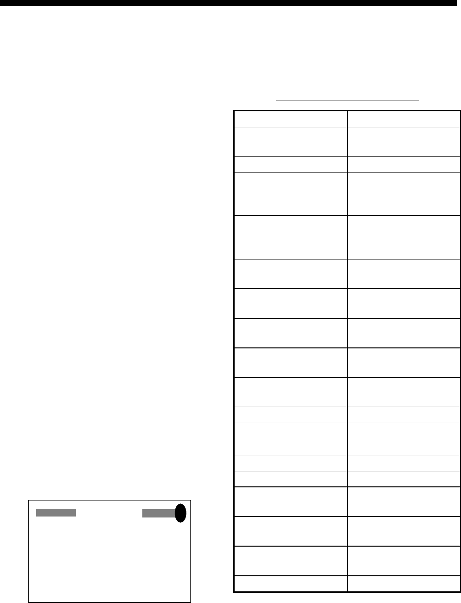
47
8. MAINTENANCE &
TROUBLESHOOTING
8.1 Maintenance
Regular maintenance is important to maintain
performance. Check the following points
monthly to help maintain performance.
• Check that connectors on the rear panel
are firmly tightened and free of rust.
• Check that the ground system is free of
rust and the ground wire is tightly fastened.
• Check that battery terminals are clean and
free of rust.
• Check the antenna for damage. Replace if
damaged.
• Dust and dirt on the keyboard and display
screen may be removed with a soft cloth.
Do not use chemical cleaners to clean the
equipment; they may remove paint and
markings. Use special care when cleaning
the LCD – it is easily scratched.
8.2 Displaying the Message
Board
The message board displays error messages
and alerts. You can display it as follows:
1. Press the [MENU] key once or twice to
open the menu.
2. Choose MESSAGES.
3. Press the [ENT] key.
MESSAGES
• NO GPS FIX!
!
MESSAGE board
4. Press the [MENU] key twice to quit the
message board.
Messages
Messages and their meanings
Message Meaning, Remedy
ANCHOR WATCH! Anchor watch alarm
violated.
ARRIVAL ALARM! Arrival alarm violated.
BACKUP ERROR
DATA/
RAM data corrupted.
Try to clear backup
data. See para. 8.4.
BATTERY ALARM! Voltage of battery in
display unit is low.
Request replacement.
NO DGPS SIGNAL! WAAS/DGPS alarm
violated. *1
GPS NO FIX! No GPS signal. Check
antenna cable.
HIGH VOLTAGE! Power source voltage
too high.
LOW VOLTAGE! Power source voltage
too low.
ODOMETER ALARM! Odometer distance
alarm violated.
RAM ERROR! Request service.
ROM ERROR! Request service.
RTC ERROR! Request service.
SPEED ALARM! Speed alarm violated.
TIME ALARM! Time alarm violated.
TRIP ALARM! Trip distance alarm
violated.
NO WAAS SIGNAL! WAAS/DGPS alarm
violated. *2
NO WAAS/DGPS
SIGNAL!
WAAS/DGPS alarm
violated. *3
XTE ALARM! XTE alarm violated.
*1 = WAAS/DGPS mode: INT/EXT BEACON
*2 = WAAS/DGPS mode: WAAS
*3 = WAAS/DGPS mode: AUTO
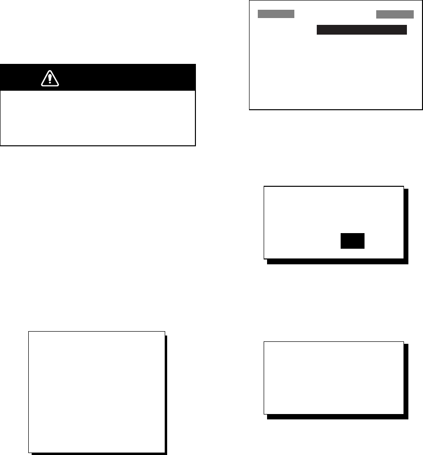
8. MAINTENANCE & TROUBLESHOOTING
48
8.3 Replacing the Fuse
The fuses (type: FGMB 125V 1A PBF, code
no.: 000-157-478-10) in the power cable (+/-
lines) protects the equipment from
overcurrent, reverse polarity of the power
source and equipment fault. If the fuse blows,
find the cause before replacing the fuse. If the
fuse blows again after replacement, request
service.
WARNING
Use the proper fuse.
Use of a wrong fuse can result in damage
to the equipment.
8.4 Replacing the Battery
A lithium battery (type: CR2354-1F2, code
no.: 000-142-305) on the circuit board inside
the display unit preserves data when the
power is turned off. The life of the battery is
3-5 years. When its voltage is low, the
message shown below appears and data is
transferred from the RAM to the flash
memory.
BATTERY ALARM!
INTERNAL BATTERY
VOLTAGE IS LOW.
REPLACE BATTERY.
PUSH ENTER KEY TO
BACKUP WPTS,
ROUTES & TRACKS.
Low battery voltage warning
When this message appears, all open
windows are closed, no alarm will be
generated and no key input other than the
[ENT] key is accepted. Press the [ENT] key to
back up data and then turn off the power.
Contact your dealer to request replacement
of the battery. Below is the procedure for
replacing the battery.
1. Turn on the power and then press the
[MENU] key once or twice to open the
menu.
2 Choose SYS SETUP and then press the
[ENT] key.
SYSTEM SETUP
LANGUAGE : ENGLISH
DATUM : WGS84
UNITS : nm, kt
TIME DIFF : +00 : 00
TIME DISP : 24HOUR
TEST?
SIMULATOR?
EXCHANGE BATTERY?
SYSTEM SETUP menu
3. Choose “EXCHANGE BATTERY?” and
then press the [ENT] key. The display
shows the following message.
ARE YOU SURE?
YES NO
EXCHANGE
BATTERY?
Exchange battery prompt
4. Press ◄ to choose YES and then press
the [ENT] key. The following display
appears.
READY FOR
BATTERY CHANGE.
PRESS ANY KEY
TO SHUT DOWN.
Battery exchange
confirmation window
5. Press any key to automatically turn off the
unit.
6. Replace the battery.
Note 1: When it is expected that the
equipment will not be used for a long time,
execute the above procedure before turning
the power off, to prevent loss of data.
Note 2: Data is copied from the flash memory
to the RAM at the next power up.
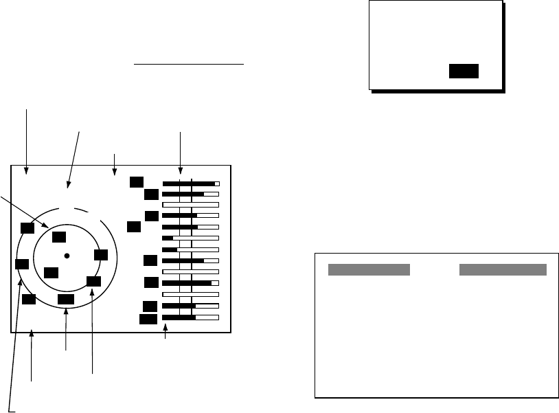
8. MAINTENANCE & TROUBLESHOOTING
49
8.5 Satellite Monitor Display
The satellite monitor display shows
information about GPS and GEO satellites.
1. Press the [MENU] key once or twice to
open the menu.
2. Choose SATELLITE.
3. Press the [ENT] key.
Number, bearing and elevation angle of
all GPS and GEO satellites (if applicable)
in view of your receiver appear. Satellites
being used in fixing position are displayed
in reverse video; satellites not being used
are shown in normal video.
D3D
N
DOP
1. 5
DOP value
Satellite number in reverse
video is used for positioning.
02
10
12
05
08
06
04
05
01
10 12
08
Altitude
North
Receiver
status
(See page 2.)
Receive signal level
Bars show signal level.
Satellites whose signal
level extends past the
dashed line are used
in fixing position.
85m
Elevation 5°
Elevation
45°
01
- -
06
07
- -
- -
07
02
04
GEO satellite
122
GEO
satellite
W
Satellite monitor display
4. Press the [MENU] key twice to quit the
SATELLITE display.
8.6 Diagnostics
The diagnostic test checks ROM, RAM, data
port, beacon receiver, battery, RTC, keyboard
and LCD for proper operation.
1. Press the [MENU] key once or twice to
open the menu.
2. Choose SYS SETUP and then press the
[ENT] key.
3. Choose “TEST?” and then press the
[ENT] key. You are asked if you are ready
to start the test.
TEST START ?
(STOP: PWR OFF)
ARE YOU SURE ?
YES NO
TEST START? prompt
4. Press ◄ to choose YES and then press
the [ENT] key to start the test.
5. The equipment tests ROM, RAM, data
port, beacon receiver, internal battery and
RTC. The results are individually
displayed as OK or NG (No Good).
TEST
ROM : OK
RAM : OK
DATA2 : - - (STOP: PWR OFF)
BEACON : OK
BATTERY : OK
RTC : OK 205-1412-0XX
XX = Program version no.
CNT: 001
085-0182-0XX
205-1411-0XX
TEST results (GP-37)
Note 1: BEACON test result shown as
NONE when no beacon receiver is
connected to the GP-32.
Note 2: DATA2 requires a special
connector to check. “- -” appears as the
result when no connector is connected.
Note 3: No program number shown for
BEACON in case of the GP-32.
Note 4: CNT shows the number of times
the test has been executed consecutively.
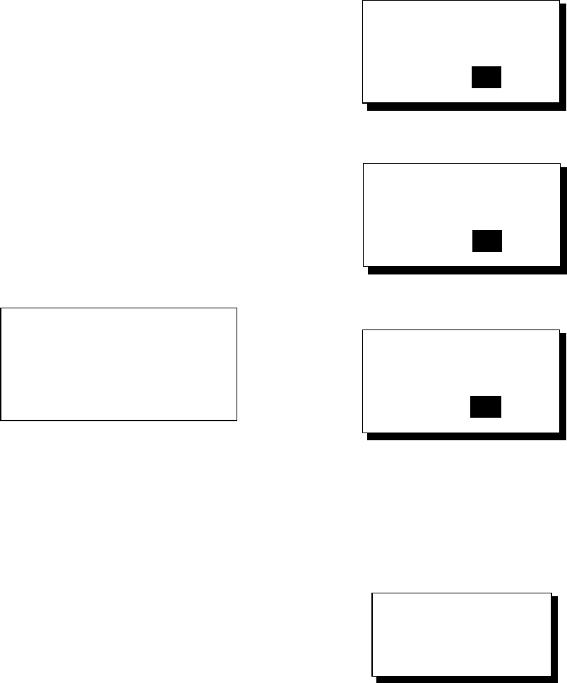
8. MAINTENANCE & TROUBLESHOOTING
50
6. After the equipment has displayed the test
results, a beep sounds and the message
PUSH KEY appears at the top right-hand
corner.
7. Press each key one by one. The name of
the key pressed momentarily appears at
the top right-hand corner if the key is
functioning properly.
Note: If no key is pressed within approx.
five seconds, the equipment automatically
proceeds to step 8.
8. The equipment displays the following
message to inform you that it is now going
to check the LCD:
<LCD CHECK>
ALL ON 2 SEC.
ALL OFF 3 SEC.
LCD check
9. The LCD is checked, and then the test is
repeated. To stop the test, turn off the
power.
8.7 Clearing Data
You may clear GPS data, menu settings and
all backup data to start afresh.
1. Press the [MENU] key once or twice to
open the menu.
2. Choose ERASE and then press the [ENT]
key.
3. Choose GPS DATA, MENU SETTINGS,
or ALL BACKUP DATA as appropriate
and then press the [ENT] key. One of the
following messages appears.
ARE YOU SURE?
YES NO
ERASE GPS DATA?
ARE YOU SURE?
YES NO
MENU SETTINGS
TO DEFAULT?
GPS DATA
MENU SETTINGS
ARE YOU SURE?
YES NO
ERASE ALL BACKUP
DATA? (DEFAULT)
BACKUP DATA
Prompt for erasure of GPS data, menu
settings, backup data
4. Press ◄ to choose YES and then press
the [ENT] key. The following display
appears.
RESTART FOR
ERASING DATA.
PUSH ANY KEY.
Prompt for restarting
5. Hit any key to erase item selected. A
beep sounds while the selected item is
being erased.
Note 1: If you were using the simulation
mode when data is cleared, the message
“Start Simulation – Are You Sure? appears.
Choose YES and press the [ENT] key to start
the simulation mode, or press the [ENT] key
to start normal operation

8. MAINTENANCE & TROUBLESHOOTING
51
Note 2: When the memory is cleared the default position is restored as below.
Language and default position, unit and time difference
Language Default Position Unit Time Difference
English 38°N, 123°W nm, kt 0:00
German 54°N, 10°E nm, kt 0:00
French 44°51E, 0°40W km, km/h 0:00
Spanish 40°26E, 3°40W nm, kt +2:00
Italian 42°N, 12°E nm, kt +1:00
Portuguese 22°44S, 43°10W nm, kt -3:00
Dutch 38°N, 123°W nm, kt 0:00
Vietnamese 12°15N, 109°13E nm, kt +7:00
Japanese 34°44N, 135°21E nm, kt +9:00
Indonesia 6°11S, 110°53E nm, kt +7:00
8. MAINTENANCE & TROUBLESHOOTING
52
(This page intentionally left blank.)
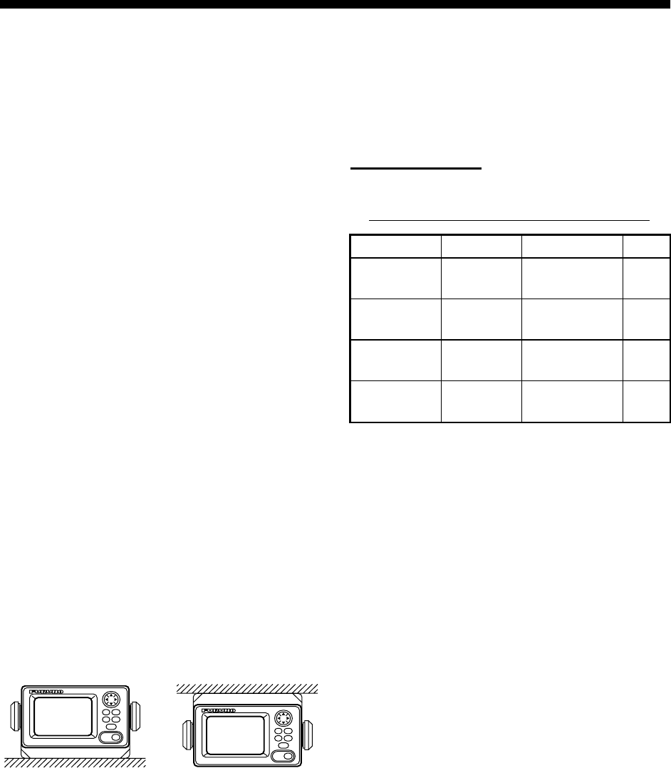
53
9. INSTALLATION
9.1 Installation of Display Unit
Mounting considerations
The display unit can be installed on a desktop,
on the overhead, or in a panel (optional flush
mounting kit required). Refer to the outline
drawings at the end of this manual for
installation instructions. When choosing a
mounting location, keep in mind the following
points:
• Locate the unit away from exhaust pipes
and vents.
• The mounting location should be well
ventilated.
• Mount the unit where shock and vibration
are minimal.
• Locate the unit away from equipment which
generates electromagnetic fields such as a
motor or generator.
• Allow sufficient maintenance space at the
sides and rear of the unit and leave
sufficient slack in cables, to facilitate
maintenance and servicing.
• Observe compass safe noted on page ii to
prevent interference to a magnetic
compass.
Desktop and overhead mounting
Desktop Overhead
Desktop and overhead mounting methods
Flush mounting
There are two types of flush mounting kits.
For details, see the outline drawings at the
end of this manual.
Flush mount F kit
Flush mount F kit
Type: OP20-29 Code No. 000-041-405
Name Type Code No. Qty
Cosmetic
panel
20-016-
1051 100-251-370 1
Tapping
screw
5X20
SUS304 000-802-840 4
Hexagon-
head bolt
M6X12
SUS304 000-862-127 2
Spring
washer
M6
SUS304 000-864-260 2
1. Using the template (supplied), cut out a
hole 92(H)X183(W) in the mounting
location.
2. Fasten the cosmetic panel to the display
unit with hexagon-head bolts and spring
washers.
3. Set the display unit to the mounting
location and fix it with tapping screws.
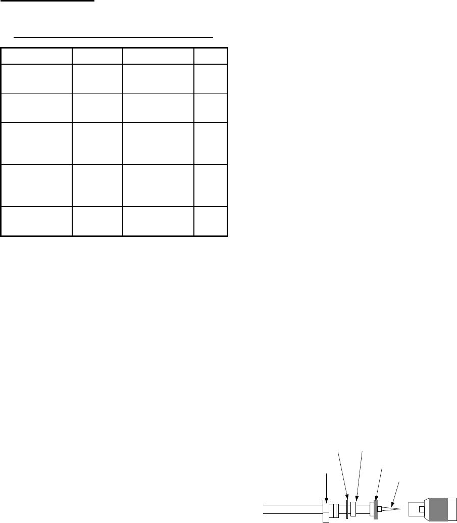
9. INSTALLATION
54
Flush mount S kit
Flush mount S kit
Type: OP20-17 Code No. 000-040-720
Name Type Code No. Qty
Flush mount
fixture
20-007-
2401 100-183-190 2
Hexagon-
head bolt
M6X12
SUS304 000-862-127 2
Wing bolt
M4X30
YBSC2
MBN12
000-804-799 4
Wing nut
M4
YBSC2
MBN12
000-863-306 4
Spring
washer
M6
SUS304 000-864-260 2
1. Using the template (supplied), cut out a
hole (92(H)X167(W)) in the mounting
location.
2. Fix the two flush mount fixtures to the
display unit with hexagon-head bolts and
spring washers.
3. Screw in wing nut in wing bolt.
4. Set the display unit to the mounting
location and fix it with wing bolts and wing
nuts from the rear side.
9.2 Installation of Antenna
Unit
Mounting considerations
Install the antenna unit referring to the
antenna installation diagram at the end of this
manual. When choosing a mounting location
for the antenna unit, keep in mind the
following points:
• Do not shorten the antenna cable.
• The antenna unit can be installed three
ways: screwed into a pipe (local supply),
fixed to a post with the optional mast
mounting kit, or screwed into an optional
mounting base. For fixing by post or pipe, it
is recommended to use stays to secure the
post or pipe to prevent damage to the GPS
receiver by vibration.
• Choose a location out of the radar beam.
The radar beam will obstruct or prevent
reception of the GPS signal.
• The location should be well away from a
VHF/UHF antenna. A GPS receiver is
interfered by a harmonic wave of a
VHF/UHF antenna.
• There should be no interfering object within
the line-of-sight to the satellites. Objects
within line-of-sight to a satellite, for
example, a mast, may block reception or
prolong acquisition time.
• Mount the antenna unit as high as possible
to keep it free of interfering objects and
water spray, which can interrupt reception
of GPS satellite signal if the water freezes.
• See the outline drawing for the antenna
unit at the back of this manual for minimum
separation distances from other antennas.
• If the antenna cable is to be passed
through a hole which is not large enough to
pass the connector, you may unfasten the
connector with a needle nose pliers and
3/8-inch open-end wrench. Refasten it as
shown below, after running the cable
through the hole.
Pin
Nut
Connector
Gasket (reddish-brown)
Spring
Washer
Shield
How to assemble the connector
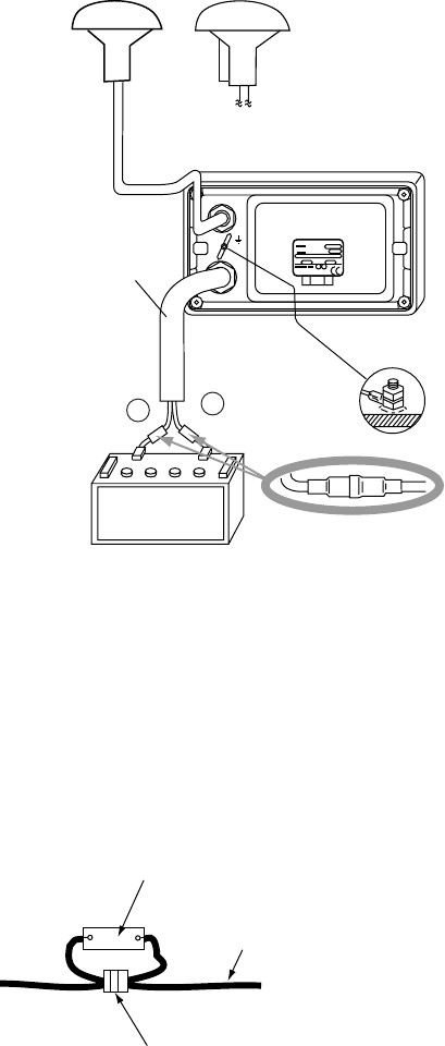
9. INSTALLATION
55
9.3 Wiring
The illustration below shows where to
connect cables on the rear of the display unit.
Please review the INSTALLATION
GUIDELINES at the front of this manual
before wiring the equipment.
Black Red
(12-24 VDC)
Ground
1A Fuse
(+/- line)
ANTENNA UNIT
GPA-017
(For GP-32)
+
-
POWER
DISPLAY UNIT
GP-32 OR GP-37
ANTENNA UNIT
GPA-019
(For GP-37)
OR
With 10 m
cable
MJ-A7SPF0009-020C,
2 m
*
* = Cut unused cores
and tape individually.
Wiring
Note: The fuse holder contains a spring that
fixes the fuse. To prevent detachment of the
spring, which would cause loss of power, tie
the line as shown below.
Fuse Holder
+ Line (Red)
- Line (Black)
Fix here.
How to fix spring in fuse holder
Grounding
The display unit contains a CPU. While it is
operating, it radiates noise, which can
interfere with radio equipment. Ground the
unit as follows to prevent interference:
• The ground wire for the display unit should
be 1.25sq or larger and as short as
possible.
• The signal ground and frame ground are
separated, however the power line is not
isolated. Therefore, do not connect the
signal ground to the frame ground when
connecting other equipment to a positive
ground battery.
External equipment
The power supply port is commonly used for
connection of external equipment such as a
radar. Refer to the interconnection diagram
on page S-1 or S-2 for connection of external
equipment.

9. INSTALLATION
56
9.4 Initial Settings
This equipment can output navigation data to
external equipment, in NMEA 0183 format.
For example, it can output position data to a
radar or echo sounder for display on its
display screen.
Output data format, data sentences
NMEA 0183 version 1.5, 2.0 or 2.1 can be
selected from the I/O SETUP menu.
DATA1: Current loop data
With waypoint
AP REM1 REM2
GLL GLL GLL
VTG GGA GGA
ZDA VTG VTG
AAM*2 ZDA ZDA
APB*2 RMC RMA (Ver 2.0)*1
BOD*2 RMB*2 GTD (Ver 1.5)*1
BWC*2 RMC
XTE*2 RMB*2
(1 s interval) (1 s interval)
BWC*2
(1 s interval:
Ver. 2.1
2 s interval:
Ver. 1.5/2.0)
*1: Output when Loran C TDs are displayed.
*2: Not output when no waypoint is set.
AP: Autopilot
REM1/REM2: Radar, echo sounder, etc.
DATA2: RS-232C level
With waypoint
AP REM
GLL GLL
VTG GGA
ZDA VTG
AAM*2 ZDA
APB*2 RMA (Ver 2.0)*1
BOD*2 GTD (Ver 1.5)*1
BWC*2 RMC
XTE*2 RMB*2
BWC*2
*1: Output when Loran C TDs are displayed.
*2: Not output when no waypoint is set.
DATA2
nocaeBlanretxE gnitteSrevieceR nocaeBlanretnI gnitteSrevieceR
tuptuO AGG KSM
tupnI foatadnoitcerroC nocaeblanretxe reviecer
lanretnifotuptuO s'reviecernocaeb atadnoitcerroc dnaatadnoitcerroc( )SSMRC$
BEACON on WAAS/DGPS
SETUP menu set to
EXT
BEACON on WAAS/DGPS
SETUP menu set to
INT
Data sentence description
Sentence Description
AAM Arrival alarm
APB Autopilot data (XTE and bearing to
waypoint)
BOD Bearing from own ship to
destination
BWC Range and bearing to waypoint
(great circle navigation)
GGA GPS position fixing condition (time
of fix, latitude, longitude, receiving
condition, number of satellites
used, DOP)
GLL Latitude and longitude
GTD Loran-C time difference
RMA Generic navigational information
(latitude, longitude, Loran-C time
differences, ground speed, true
course
RMB Generic navigational information
(cross track error, steering
direction, starting waypoint no.,
destination waypoint no., latitude
and longitude of starting waypoint,
latitude and longitude of destination
waypoint, range and bearing to
waypoint, range and bearing from
present position to destination
waypoint, velocity to destination,
arrival alarm)
RMC
Generic navigational information
(UTC time, latitude, longitude,
ground speed, true course, day,
month, year)
VTG Actual track and ground speeds
XTE Course error amount and direction
to steer
ZDA UTC time (day, month, year)

9. INSTALLATION
57
Output setting
1. Press the [MENU] key once or twice to
open the menu.
2. Choose I/O SETUP.
3. Press the [ENT] key.
I/O SETUP
DATA1 : NMEA-REM1
DATA2 : NMEA-REM
NMEA VER : VER2.0
SAVE WPT/RTE → PC?
LOAD WPT/RTE ← PC?
LOAD WPT← YEOMAN?
WIRING INFO?
I/O SETUP menu
4. Choose DATA1, DATA2 or NMEA VER as
appropriate.
5. Press the [ENT] key. One of the following
screens appears depending on the item
selected at step 4.
NMEA-REM1
NMEA-REM2
NMEA-AP
For DATA1
NMEA-REM
NMEA-AP
RTCM-OUT*
For DATA2
VER 1.5
VER 2.0
VER 2.1
For NMEA
Version
*= For GP-37, fixed at "BEACON" when MODE
on DGPS/WAAS menu is set to EXT BEACON.
DATA1, DATA 2 and NMEA version options
6. Use ▲ or ▼ to choose desired option.
NMEA-REM1, 2: Output data to radar,
echo sounder, etc.
NMEA-AP: Output data to an autopilot.
RTCM-OUT: Choose when equipped with
internal DGPS beacon receiver (GP-37).
VER 1.5, 2.0, 2.1: Choose the NMEA
version of external equipment. If you are
unsure of the version number, try both
and choose the one which successfully
outputs data.
7. Press the [ENT] key.
8. Press the [MENU] key twice to finish.
9. INSTALLATION
58
(This page intentionally left blank.)
AP-1
APPENDIX
Menu Tree
Default settings shown in bold italics.
WAYPOINTS
LIST
, NEAREST
ROUTES VOYAGE ROUTE (START,
STOP
)
INTERVAL (TIME, 00H01M - 99H99M,
00H10M
;
DISTANCE
, 0.1 - 99.9 nm,
2 nm
)
PLOTTER TRACK REC (OFF,
DISTANCE
, AUTO)
INTERVAL (
0.10 nm
)
BRG. REF (
MAG
, TRUE)
MAG. VAR. (
AUTO
, MAN)
WPT NAME (
DSP GOTO
, DSP ROUTE, DSP ALL)
TTG/ETA SPD (
AUTO
, MAN)
ALARMS BUZZER (SHORT,
LONG
, CONSTANT)
ARV/ANC (
OFF
, ARV, ANC)
XTE (
OFF
, ON)
SPEED (
OFF
, LOW, HIGH)
WAAS/DGPS (
OFF
, ON)
TIME (
OFF
, ON)
TRIP (
OFF
, ON)
ODOMETER (
OFF
, ON)
WAYPOINTS/MARKS?
ROUTES?
TRACK?
RESET TRIP?
RESET ODO?
GPS DATA?
MENU SETTINGS?
ALL BACKUP DATA?
ERASE
WAAS/DGPS MODE (
GPS
, WAAS, INT BEACON, EXT BEACON, AUTO)
WAAS SEARCH (
AUTO
, MANUAL)
CORRECTIONS DATA SET (00-99, 02)
DGPS STATION (
AUTO
, MANUAL, LIST)
RATE (50, 100,
200
BPS)
FREQ (
310.0
kHz)
MENU
(Continued on next page)
CALCULATE
MESSAGES
SATELLITE
Displays operational messages.
Shows satellite status display.
MODE (
WAYPOINTS
, ROUTE), SPD (
AUTO
, MAN)
APPENDIX
AP-2
* = For GP-37. Replaced with "BEACON" when MODE on DGPS/WAAS menu
is set to EXT BEACON.
(Continued from previous page)
I/O SETUP DATA1 (
NMEA-REM1
, NMEA-REM2,
NMEA-AP)
DATA2 (
NMEA-REM
, NMEA-AP, RTCM-OUT*)
NMEA VER (VER 1.5,
VER 2.0
, VER 2.1)
SAVE WPT/RTE → PC?
LOAD WPT/RTE ← PC?
LOAD WPT ← YEOMAN?
WIRING INFO?
TD SETUP DISPLAY (
XX.XXX'
, XX'XX.X" LC TD, DE TD)
LORAN C (
7980: 23-43
)
LORAN C ∆TD1, ∆TD2 (-99.9-+99.9;
+00.0
)
DECCA (
25: G-P
)
DECCA ∆TD1, ∆TD2 (-9.99-+9.99;
+0.0
)
LANGUAGE (
ENGLISH
, FRANCAIS, PORTUGUES, NEDERLANDS,
TIENG VIET, ESPANOL, ITALIANO, DEUTSCH, (JAPANESE), INDONES)
DATUM (
WGS84
, WGS72, OTHER)
UNITS (
nm, kt
; km, km/h; sm, mph)
TIME DIFF (
+00:00
)
TIME DISP (12HOUR,
24HOUR
)
TEST?
SIMULATOR? (MODE: ON,
OFF
, SPEED: 0-99 kt,
20 kt
,
COURSE:
MAN (40 )
, AUTO
; LAT,
38
°
00'N
, LON,
123
°
00'W
)
EXCHANGE BATTERY?
SYS SETUP
SMOOTH POS (0-999 SEC;
0 SEC
)
SMOOTH S/C (0-9999 SEC;
5 SEC
)
AVR. SPEED (0-9999 SEC;
60 SEC
)
LAT OFFSET
LON OFFSET
DISABLE SV (Disable GPS satellite.)
FIX MODE (2D/
2/3D
) For 2D, default antenna height is 5 m.
GPS SETUP
USER DISP 1 (OFF, DIGITAL
SPEEDOMETER)
2 (OFF, DIGITAL
SPEEDOMETER)
START FROM (-99 to +99; 0)
INTERVAL (01 to 99; 10)
SPEEDOMETER
DIGITAL (Display division: , , ,
Available data: Odometer,
trip
, time,
position, power voltage, SOG, COG,
range and bearing to waypoint, XTE,
TTG and ETA)
APPENDIX
AP-3
Geodetic Chart List
001: WGS84
002: WGS72
003: TOKYO : Mean Value (Japan, Korea &
Okinawa)
004: NORTH AMERICAN 1927 : Mean Value (CONUS)
005: EUROPEAN 1950 : Mean Value
006: AUSTRALIAN GEODETIC 1984 : Australia & Tasmania
007: ADINDAN : Mean Value (Ethiopia & Sudan)
008: : Ethiopia
009: : Mali
010: : Senegal
011 : Sudan
012: AFG : Somalia
013: AIN EL ABD 1970 : Bahrain Is.
014: ANNA 1 ASTRO 1965 : Cocos Is.
015: ARC 1950 : Mean Value
016: : Botswana
017: : Lesotho
018: : Malawi
019: : Swaziland
020: : Zaire
021: : Zambia
022: : Zimbabwe
023: ARC 1960 : Mean Value (Kenya & Tanzania)
024: : Kenya
025: : Tanzania
026: ASCENSION IS. 1958 : Ascension Is.
027: ASTRO BEACON ÒEÓ : Iwo Jima Is.
028: ASTRO B4 SOR. ATOLL : Tern Is.
029: ASTRO POS 71/4 : St. Helena Is.
030: ASTRONOMIC STATION 1952 : Marcus Is.
031: AUSTRALIAN GEODETIC 1966 : Australia & Tasmania
032: BELLEVUE (IGN) : Efate & Erromango Islands
033: BERMUDA 1957 : Bermuda Islands
034: BOGOTA OBSERVATORY : Columbia
035: GAUPO INCHAUSPE : Argentina
036: CANTON IS. 1966 : Phoenix Islands
037: CAPE : South Africa
038: CAPE CANAVERAL : Mean Value (Florida & Bahama
Islands)
039: CARTHAGE : Tunisia
040: CHATHAM 1971 : Chatham Is. (New Zealand)
041: CHUA ASTRO : Paraguay
042: CORREGO ALEGRE : Brazil
043: DJAKARTA (BATAVIA) : Sumatra Is. (Indonesia)
044: DOS 1968 : Gizo Is. (New Georgia Is.)
045: EASTER IS. 1967 : Easter Is.
046: EUROPEAN 1950 (Con’t) : Western Europe
047: : Cyprus
048: : Egypt
049: : England, Scotland, Channel &
Shetland Islands
050: : England, Ireland, Scotland, &
Shetland Islands
051: : Greece
052 : Iran
053: : Italy, Sardinia
054: : Italy, Sicily
055: : Norway & Finland
056: : Portugal & Spain
057: EUROPEAN 1979 : Mean Value
058: GANDAJIKA BASE : Republic of Maldives
059: GEODETIC DATUM 1949 : New Zealand
060: GUAM 1963 : Guam Is.
061: GUX 1 ASTRO : Guadalcanal Is.
062: HJORSEY 1955 : Iceland
063: HONG KONG 1363 : Hong Kong
064: INDIAN : Thailand & Vietnam
065: : Bangladesh, India & Nepal
066: IRELAND 1965 : Ireland
067: ISTS 073 ASTRO 1969 : Diego Garcia
068: JOHNSTON IS. 1961 : Johnston Is.
069: KANDAWALA : Sri Lanka
070: KERGUELEN IS. : Kerguelen Is.
071: KERTAU 1948 : West Malaysia & Singapore
072: LA REUNION : Mascarene Is.
073: L. C. 5 ASTRO : Cayman Brac Is.
074: LIBERIA 1964 : Liberia
075: LUZON : Philippines (excl. Mindanao Is.)
076: : Mindanao Is.
077: MAHE 1971 : Mahe Is.
078: MARCO ASTRO : Salvage Islands
079: MASSAWA : Eritrea (Ethiopia)
080: MERCHICH : Morocco
081: MIDWAY ASTRO 1961 : Midway Is.
082: MINNA : Nigeria
083: NAHRWAN : Masirah Is. (0man)
084: : United Arab Emirates
085: : Saudi Arabia
086: NAMIBIA : Namibia
087: MAPARIMA, BWI : Trinidad & Tobago
088: NORTH AMERICAN 1927 : Western United States
089: : Eastern United States
090: : Alaska
091: : Bahamas (excl. San Salvador Is.)
092: : Bahamas, San Salvador Is.
093: : Canada (incl. Newfoundland Is.)
094: : Alberta & British Columbia
095: : East Canada
096: : Manitoba & Ontario
097: : Northwest Territories &
Saskatchewan
098: : Yukon
099: : Canal Zone
100: : Caribbean
101: : Central America
102: : Cuba
103: : Greenland
104: : Mexico
105: NORTH AMERICAN 1983 : Alaska
106: : Canada
107: : CONUS
108: : Mexico, Central America
109: OBSERVATORIO 1966 : Corvo & Flores Islands (Azores)
110: OLD EGYPTIAN 1930 : Egypt
111: OLD HAWAIIAN : Mean Value
112: : Hawaii
113: : Kauai
114: : Maui
115: : Oahu
116: OMAN : Oman
117: ORDNANCE SURVEY OF GREAT BRITAIN 1936: Mean Value
118: : England
119: : England, Isle of Man & Wales
120: : Scotland, & Shetland Islands
121: : Wales
122: PICO DE LAS NIVIES : Canary Islands
123: PITCAIRN ASTRO 1967 : Pitcairn Is.
124: PROVISIONS SOUTH CHILEAN 1963: South Chile (near 53°S)
125: PROVISIONAL SOUTH AMERICAN 1956: Mean Value
126: : Bolivia
127: : Chile-Northern Chile (near 19°S)
128: : Chile-Southern Chile (near 43°S)
129: : Columbia
130: : Ecuador
131: : Guyana
132: : Peru
133: : Venezuela
134: PUERTO RICO : Puerto Rico & Virgin Islands
135: QATAR NATIONAL : Qatar
136: QORNOQ : South Greenland
137: ROME 1940 : Sardinia Islands
138: SANTA BRAZ : Sao Maguel, Santa Maria
Islands (Azores)
139: SANTO (DOS) : Espirito Santo Is.
140: SAPPER HILL 1943 : East Falkland Is.
141: SOUTH AMERICAN 1969 : Mean Value
142: : Argentina
143: : Bolivia
144: : Brazil
145: : Chile
146: : Columbia
147: : Ecuador
148: : Guyana
149: : Paraguay
150: : Peru
151: : Trinidad & Tobago
152: : Venezuela
153: SOUTH ASIA : Singapore
154: SOUTHEAST BASE : Porto Santo & Madeira Islands
155: SOUTHWEST BASE : Faial, Graciosa, Pico, Sao
Jorge, & Terceira Is.
156: TIMBALAI 1948 : Brunei & East Malaysia
(Sarawak & Sadah)
157: TOKYO : Japan
158: : Korea
159: : Okinawa
160: TRISTAN ASTRO 1968 : Tristan da Cunha
161: VITI LEVU 1916 : Viti Levu Is. (Fiji Islands)
162: WAKE-ENIWETOK 1960 : Marshall Islands
163: ZANDERIJ : Surinam
164: BUKIT RIMPAH : Bangka & Belitung Islands
(Indonesia)
165: CAMP AREA ASTRO : Camp Mcmurdo Area, Antarctica
166: G. SEGARA : Kalimantan Is. (Indonesia)
167: HERAT NORTH : Afghanistan
168: HU-TZU-SHAN : Taiwan
169: TANANARIVE OBSERVATORY 1925 : Madagascar
170: YACARE : Uruguay
171: RT-90 : Sweden
172: Pulkovo 1942 : Russia
173: FINNISH KKJ : Finland

APPENDIX
AP-4
Loran C Chains
niahCIRG1S2S3S4S5S
cificaPlartneC09941192–––
tsaoCtsaEnaidanaC0395115283––
)aeroK(noiLodnammoC0795111324––
tsaoCtseWnaidanaC0995117214––
aibarAiduaShtuoS071711629325–
aeSrodarbaL03971162–––
aissuRnretsaE059711036416–
aksalAfofluG0697116244––
aeSnaigewroN079711626406–
ASUtsaehtuoS089711323495–
aeSnaenarretideM0997119274––
aissuRnretseW000801520556–
ASUlartneChtroN0928117224––
aibarAiduaShtroN09981152046596
sekaLtaerG079811824495–
ASUlartneChtuoS01691152042556
ASUtsaoCtseW0499117204––
ASUtsaehtroN069911529345–
)dlo(cificaPtsaehtroN079911035518–
cidnalecI08991103–––
cificaPhtroN0999119234––
zeuS19940142
ecnarF,dnalgnE04982103
cificaPtsewhtroN039811030507
tsaoCtsaEdnaldnuofweN07271152
yasseL13760193
ØB10071172
tlyS99471162
edjE7009013283
htroNaibarAaiduaS038811529365
htuoSaibarAaiduaS030711527355

APPENDIX
AP-5
Decca Chains
niahC .oN niahCniahC edoc noitacoLniahC .oN niahCniahC edoc noitacoL
10citlaBhtuoSA0eporuE52karregakSB01"
20tednaltseVE0" 62fluGnaisrePhtroNC5&fluGnaisreP aidnI
30hsitirBtsewhtuoSB1" 72fluGnaisrePhtuoSC1"
40nairbmuhtroNA2" 82yabmoBB7"
50dnalloHE2" 92attuclaCB8"
60hsitirBhtroNB3" 03hsedalgnaBC6"
70netofoLE3" 13hayilaSF2"
80F3" 23odiakkoHC9napaJ
90citlaBhtroNB4" 33ukohoTC6"
01tseWhtroNC4" 43otnaKC8napaJ
11galednorTE4" 53ukokihSC4"
21hsilgnEB5" 63ukirukoHC2"
31nainhtoBhtroNF5" 73uhsuyKatiKC7"
41hsinapSnrehtuoSA6" 83dnalauqamaNA4acirfAnrehtuoS
51hsittocShtroNC6" 93epaCA6"
61dnalniFfofluGE6" 04ecnivorPnretsaEA8"
71hsinaDB7" 14acirfAtseWhtuoSC9"
81hsirID7" 24lataNC01"
91kramnniFE7" 34reipmaDE8ailartsuA
02hcnerFB8" 44dnaldaeHtroPA4"
12nainhtoBhtuoSC8" 54itsocitnAC9aciremAnrehtroN
22naedirbeHE8" 64dnaldnuofweNtsaEC2"
32sdnalsInaisirFB9" 74tiartStobaCB6"
42dnalegleHE9" 84aitocSavoNC7"
APPENDIX
AP-6
(This page intentionally left blank.)
SP - 1 E4420S01C-M
SPECIFICATIONS OF
GPS NAVIGATOR GP-32
DGPS NAVIGATOR GP-37
1 GPS RECEIVER
1.1 Receiving Channels
GPS 12 channels parallel, 12 satellites tracking
WAAS 1 channel
1.2 Rx Frequency 1575.42 MHz
1.3 Rx Code C/A code, WAAS
1.4 Position Fixing System All in view, 8-state Kalman filter
1.5 Position Accuracy
GPS 10 m (95% of the time, HDOP=4)
DGPS 5 m (95% of the time, external data required)
WAAS 3 m (95% of the time)
1.6 Tracking Velocity 999 kt
1.7 Position-Fixing Time Warm start: 12 s approx., Cold start: 90 s approx.
1.8 Position Update interval 1 s
1.9 Beacon Receiver (GP-37 only)
Frequency Range 283.5 kHz to 325.0 kHz
MSK Rate 50,100,200 bps (Auto/Manual selectable)
2 RECEIVER UNIT
2.1 Display System Monochrome LCD, 95 (W) x 60 (H) mm, 120 x 64 dots
2.2 Display Mode Plotter, Steering, Highway, NAV data, Destination, User display
2.3 Projection Mercator
2.4 Memory Capacity Track: 1000 pts, Waypoint: 999 pts w/ comment
2.5 Storage Capacity 50 routes w/ 30 waypoint each
2.6 Alarms Arrival and anchor watch, Cross track error, Odometer alarm,
Ship’s speed in and out alarms, Time alarm, Trip alarm,
WAAS/DGPS alarm
2.7 Display Scale
Plotter Display 0.02/0.05/0.1/0.2/0.5/1/2/5/10/20/40/80/160/320 nm
Highway Display 0.2/0.4/0.8/1/02/4/8/16 nm
3 INTERFACE
3.1 Data 1 Current Loop
Output Data: NMEA0183 Ver 1.5/2.0/2.1 selected
SP - 2 E4420S01C-M
NMEA-REM1: GLL, GGA, VTG, ZDA, RMC, RMB
NMEA-REM2: GLL, GGA, VTG, ZDA, RMC, RMB, BWC,
RMA (Ver2.0), GTD (Ver1.5) when TD indication selected
NMEA-AP: GLL, VTG, ZDA, AAM, APB, BOD, BWC, XTE
3.2 Data 2 RS-232C
Output Data: NMEA0183 Ver 1.5/2.0/2.1 selected
NMEA-REM: GLL, GGA, VTG, ZDA, RMC, RMB, BWC,
RMA (Ver2.0), GTD (Ver1.5) when TD indication selected
NMEA-AP: GLL, VTG, ZDA, AAM, APB, BOD, BWC, XTE
DGPS RTCM SC-104 (GP-37 only)
Downloading to PC (WP/ Route Data)
Input Data: DGPS RTCM SC-104 Ver 2.1
Uploading from PC (WP/ Route Data)
NMEA WPL (WP Data)
4 POWER SUPPLY
4.1 GP-32: 12-24 VDC: 240-120 mA
4.2 GP-37: 12-24 VDC: 340-170 mA
5 ENVIRONMENTAL CONDITION
5.1 Ambient Temperature Antenna unit: -25°C to +70°C
Receiver unit: -15°C to +55°C
5.2 Damp Heat 93% or less at 40°C
5.3 Waterproofing Antenna unit: IPX6
(IEC 60529) Receiver unit: IPX5 (USCG CFR-46)
5.4 Vibration IEC 60945
6 COATING COLOR
6.1 Antenna Unit N9.5
6.2 Receiver Unit Chassis: 2.5GY5/1.5, Panel: N3.0
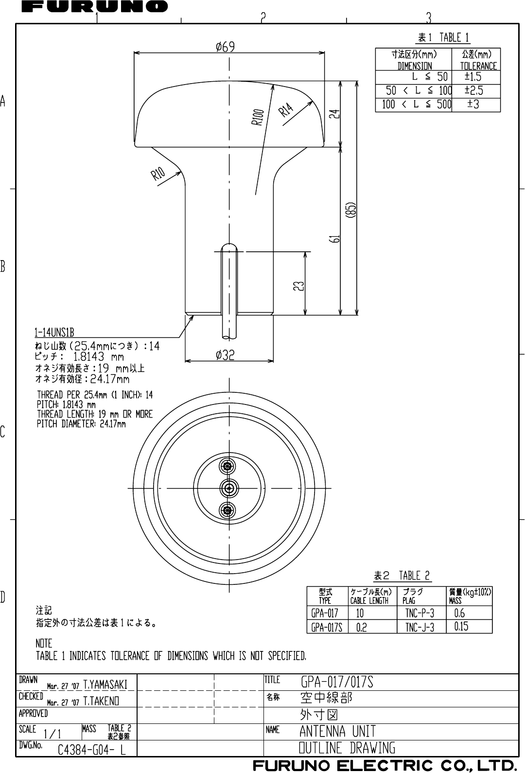
/CT4'UWOK
Sep.29'05
D - 1
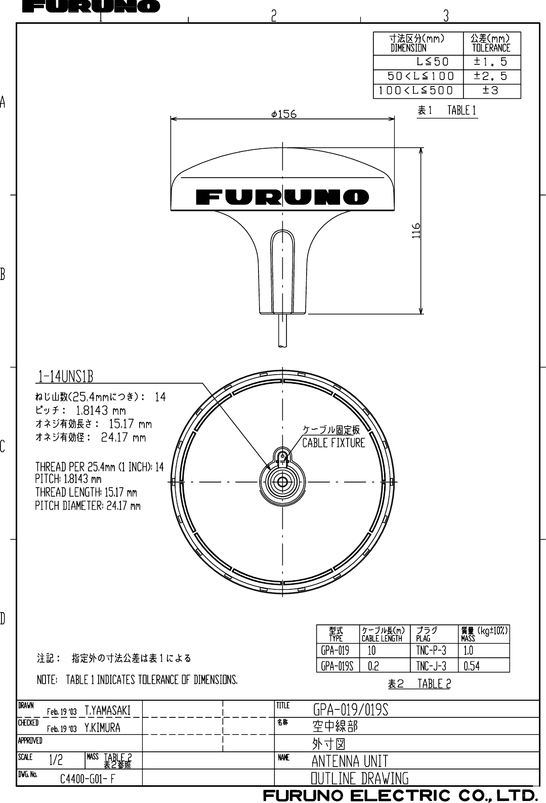
Feb. 19, '03
D - 2
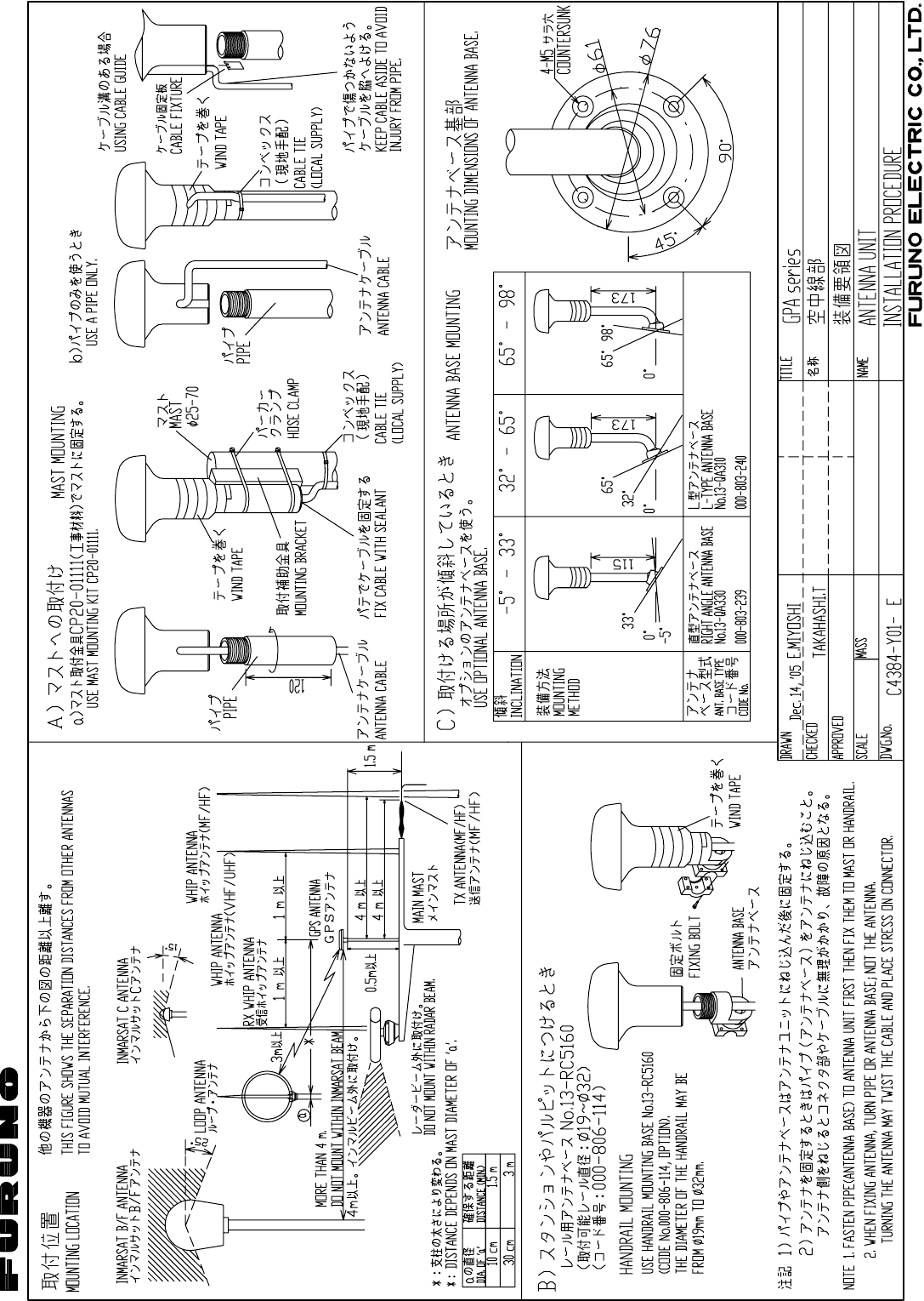
Y
. Hatai
hatai
2005.12.19
11:57:12
+09'00'
D-2A
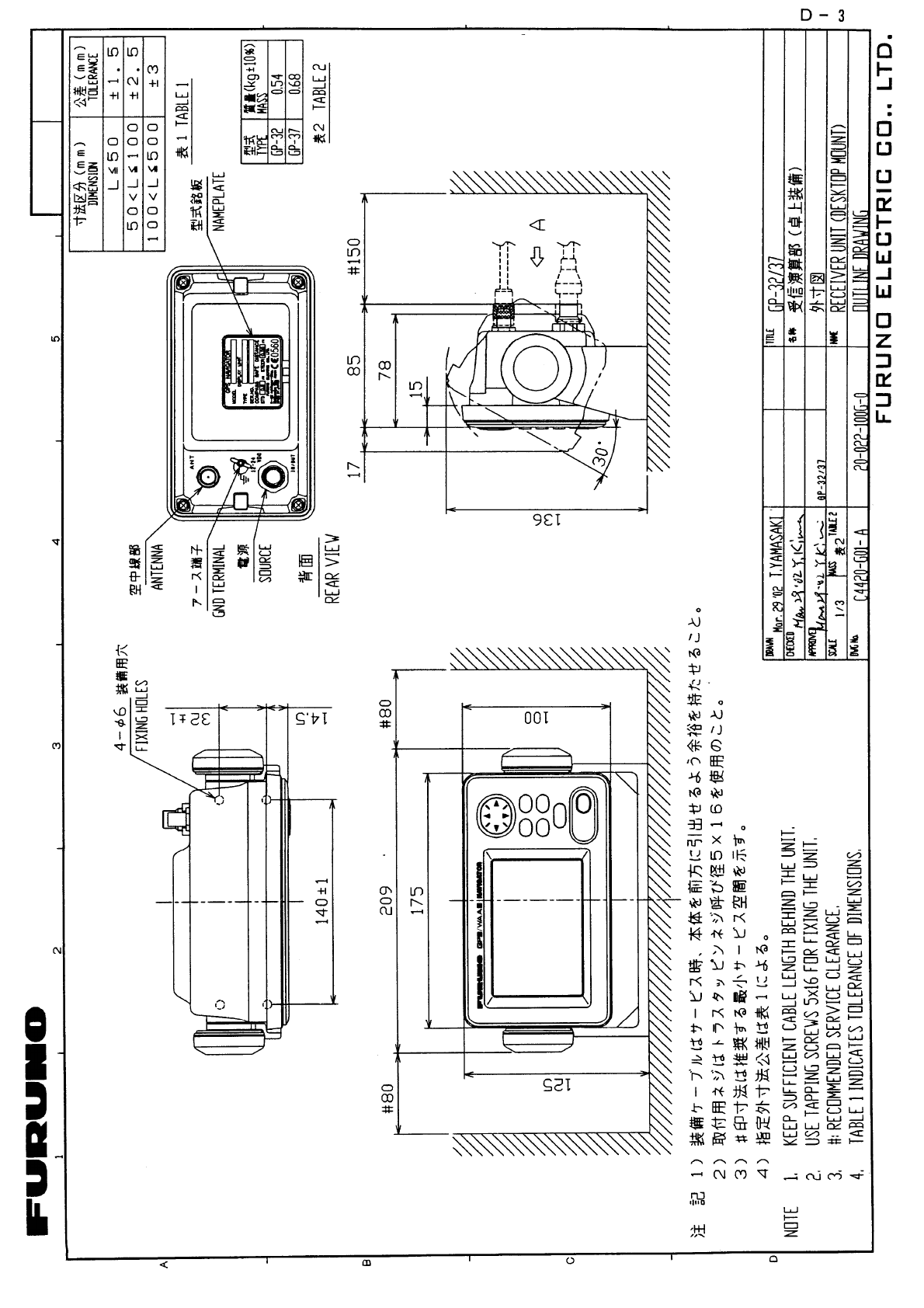
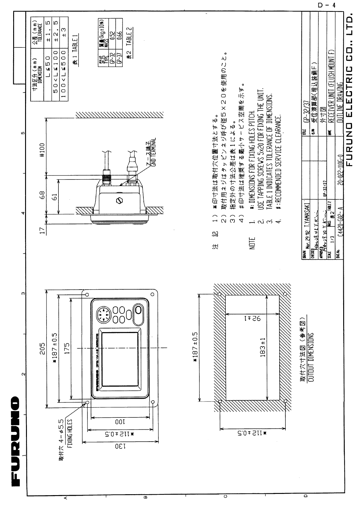
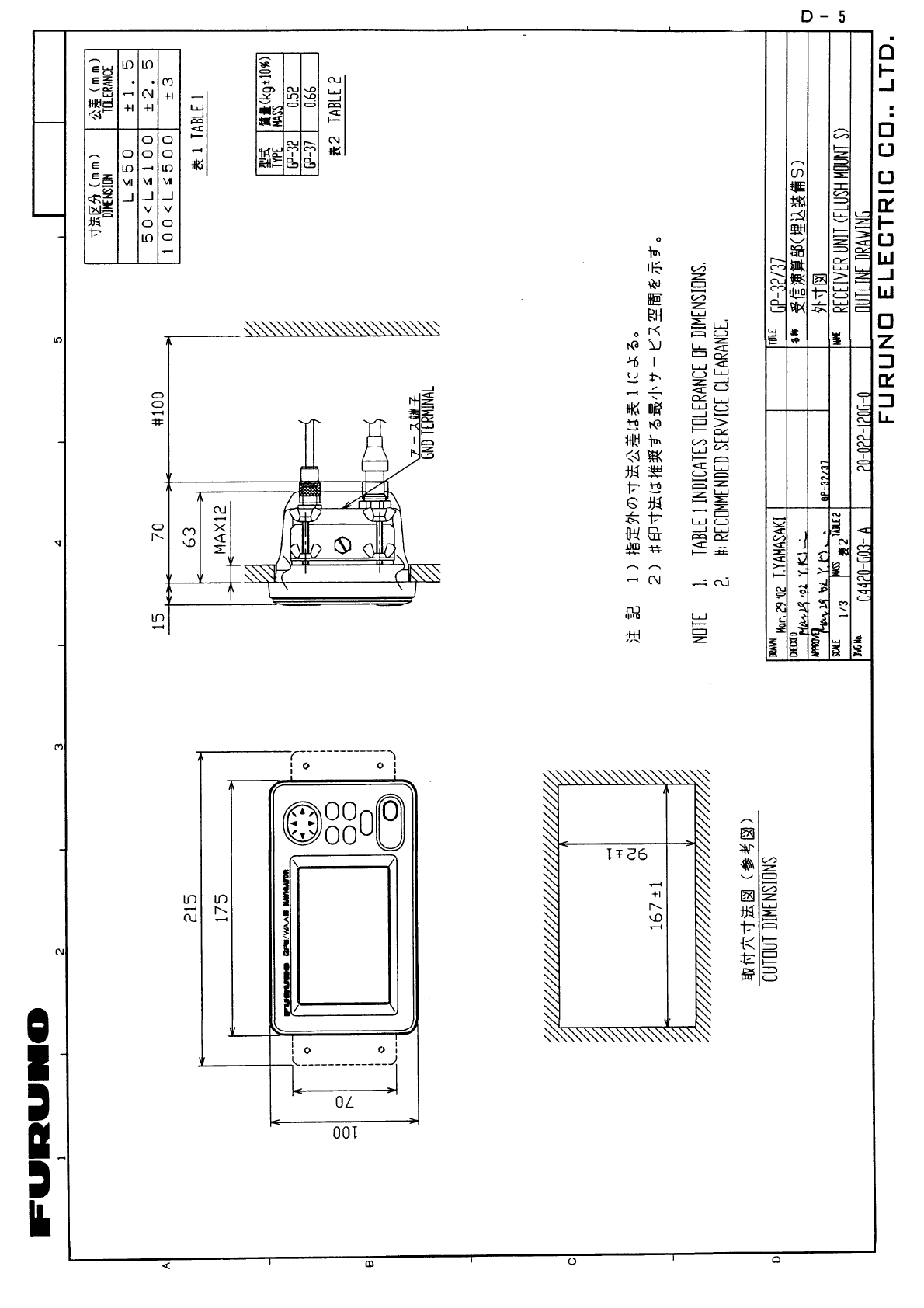
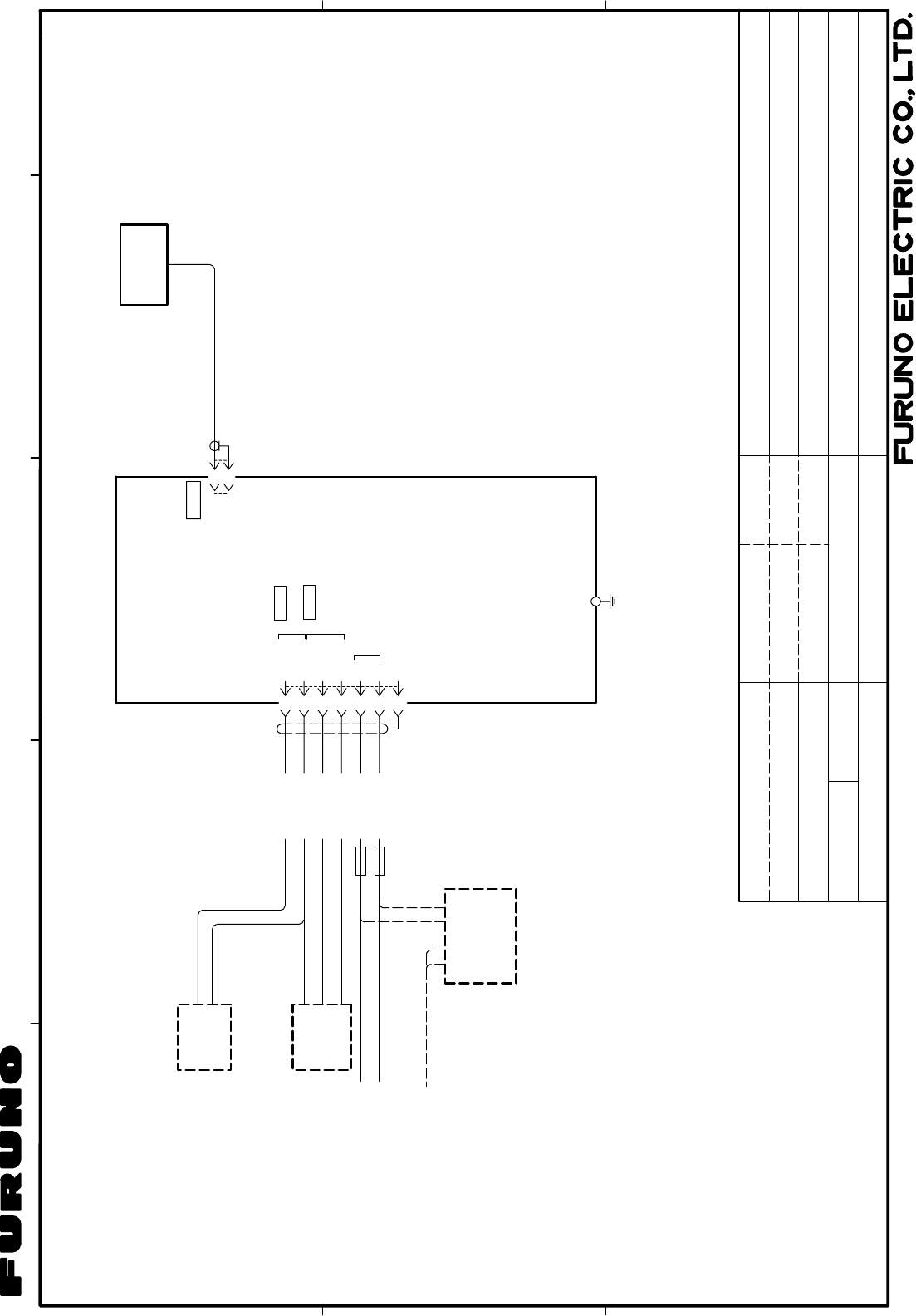
C
B
1
A
34
2
相互結線図
INTERCONNECTION DIAGRAM
TITLE
名称
NAME
kg
*4. SELECT ON MENU.
NOTE
*2. FITTED AT FACTORY.
*1. LOCAL SUPPLY.
*4)メニューにより選択
*1)現地手配
注記
*2)コネクタは工場にて取付済み
*3)オプション
3D-2V,10m,φ5.3
TNC-P-3
ANT
空中線部
ANTENNA UNIT
1A
SD 4
3
2
*2
MJ-A7SPFD
1
J1
5
6
7
SD
(+)
(-)
FG
RD
TD-H
TD-C/SG
12-24VDC IN
RD
SG
12-24 VDC
SHIP'S MAINS
船内電源 (+)
(-)
PC RS-232C
CURRENT LOOP
(WP,ROUTE)
UP LOAD/DOWN LOAD
DATA1
*4
DATA2
FUSE
RD-H
RD-C
GND
IV-1.25SQ
*1
キ
アオ
シロ
アカ
クロ
YEL
BLU
WHT
RED
BLK
ミドリ GRN
*3. OPTION.
受信演算部
RECEIVER UNIT
1φ,50/60Hz
100/110/115/
220/230 VAC
RECTIFIER
整流器
GPS航法装置
GPS NAVIGATOR
GP-32
GP-32
GPA-017
例)
魚群探知機
オートパイロット
リモートディスプレイ
EXT EQUIPMENT
EX:
RADAR
AUTOPILOT
REMOTE DISPLAY
レーダー
プロッタ
PLOTTER
ECHO SOUNDER
外部機器
*1
(+)(-)
1A
MJ-A7SPF0009,2m
RTCM SC-104
パーソナルコンピュータ
PC
外部ビーコン受信機
EXTERNAL BEACON RECEIVER
C4420-C01- B
T.YAMASAKI
May 13 '03
May 13 '03
T.TAKENO
SCALE
APPROVED
CHECKED
DRAWN
DWG.No.
MASS
NMEA0183(Ver1.5/2.0/2.1)
NMEA0183(Ver1.5/2.0/2.1)
May 13 '03
S - 1

C
B
1
A
34
2
相互結線図
INTERCONNECTION DIAGRAM
TITLE
名称
NAME
MASS kg
DGPS航法装置
DGPS NAVIGATOR
*4. SELECT ON MENU.
NOTE
*2. FITTED AT FACTORY.
*1. LOCAL SUPPLY.
*4)メニューにより選択
*1)現地手配
注記
*2)コネクタは工場にて取付済み
*3)オプション
3D-2V,10m,φ5.3
TNC-P-3
ANT
空中線部
GPA-019
ANTENNA UNIT
1A
SD 4
3
2
*2
MJ-A7SPFD
1
J1
5
6
7
SD
(+)
(-)
FG
RD
TD-H
TD-C/SG
12-24VDC IN
RD
SG
12-24 VDC
SHIP'S MAINS
船内電源 (+)
(-)
PC RS-232C
CURRENT LOOP
RTCM SC-104[OUTPUT]
(WP,ROUTE)
UP LOAD/DOWN LOAD
DATA1
*4
DATA2
RD-H
RD-C
パーソナルコンピュータ
PC
GP-37
GND
IV-1.25SQ
*1
キ
アオ
シロ
アカ
クロ
YEL
BLU
WHT
RED
BLK
ミドリ GRN
*3. OPTION.
受信演算部
RECEIVER UNIT
GP-37
1φ,50/60Hz
100/110/115/
220/230 VAC
RECTIFIER
整流器
例)
魚群探知機
オートパイロット
リモートディスプレイ
EXT EQUIPMENT
EX:
RADAR
AUTOPILOT
REMOTE DISPLAY
レーダー
プロッタ
PLOTTER
ECHO SOUNDER
外部機器
MJ-A7SPF0009,2m
1A
*1
(+)(-)
FUSE
C4419-C01- B
SCALE
APPROVED
CHECKED
DRAWN
DWG.No.
T.YAMASAKI
May 13 '03
May 13 '03
T.TAKENO
NMEA0183(Ver1.5/2.0/2.1)
NMEA0183(Ver1.5/2.0/2.1)
May 13 '03
S - 2

Index-1
INDEX
A
Alarms
anchor watch ............................................30
arrival ........................................................29
buzzer type ...............................................32
odometer...................................................32
speed ........................................................31
time ...........................................................31
trip .............................................................32
WAAS/DGPS ............................................31
XTE...........................................................30
Alarms menu ................................................29
Anchor watch alarm......................................30
Arrival alarm .................................................29
B
Battery replacement .....................................48
Bearing reference.........................................37
Buzzer...........................................................32
C
Calculation menu..........................................33
Centering (own ship mark) ...........................10
Clearing data ................................................50
Contrast ..........................................................2
Controls ..........................................................1
Cursor.............................................................9
D
Decca chains............................................AP-5
Destination
canceling...................................................28
setting by cursor .......................................27
setting by route .........................................28
setting by user waypoint...........................28
setting by waypoint ...................................27
DGPS
editing user channels................................36
erasing all user channels..........................37
erasing individual user channels ..............37
programming user channels.....................36
setup .........................................................35
Diagnostics ...................................................49
Digital display
overview ..................................................... 6
setting up.................................................. 41
DIM/PWR key................................................. 2
Dimmer........................................................... 2
DISP key ........................................................ 3
Downloading data to a PC ........................... 43
E
Erasing
routes
track...........................................................11
waypoints (marks).................................... 17
F
Fuse replacement ........................................ 48
G
Geodetic chart system
list ......................................................... AP-3
selection ................................................... 38
GOTO key .............................................. 27, 28
GPS setup menu.......................................... 40
H
Highway display ............................................. 4
I
Installation ................................................... 53
L
Language ..................................................... 46
Loran C chains......................................... AP-4
M
Magnetic variation........................................ 38
Maintenance................................................. 47
MARK/MOB key........................................... 15
MENU key...................................................... 7
Menu tree................................................. AP-1
Messages..................................................... 47
MOB mark .................................................... 15
N
Nav data display ............................................ 5
O
Odometer alarm ........................................... 32
Odometer resetting ...................................... 42
INDEX
Index-2
P
Plotter display.................................................4
Position offset...............................................40
R
Receiver status indications ............................2
Routes
changing route name................................25
creating track-based.................................22
creating with cursor ..................................19
creating with waypoints ......................20, 21
deleting waypoints from............................24
destination ................................................28
erasing ......................................................25
inserting waypoints...................................24
replacing waypoints..................................23
skipping waypoints ...................................24
S
Satellite disabling .........................................40
Satellite monitor............................................49
Shifting the display .......................................10
Simulation display ..........................................8
Smoothing
position .....................................................40
speed/course ............................................41
Speed alarm .................................................31
Speed averaging ..........................................40
Speedometer display
overview......................................................6
setting up ..................................................42
Steering display..............................................5
System configuration..................................... vi
T
TD setup menu.............................................38
Time..............................................................39
Time alarm....................................................31
Track
erasing.......................................................11
plotting interval ......................................... 10
starting, stopping plotting ......................... 10
Trip alarm ..................................................... 32
Trip resetting ................................................ 42
U
Units of measurement.................................. 38
Uploading data from a PC ........................... 44
User display
overview ..................................................... 6
setting up.................................................. 41
User waypoint .............................................. 28
W
WAAS
description................................................. vii
setup......................................................... 34
WAAS/DGPS alarm ..................................... 31
WAAS/DGPS menu ............................... 34, 35
Waypoints (marks)
displaying name ....................................... 16
editing....................................................... 16
entering at own ship position ................... 14
entering through the waypoint list ............ 14
entering with cursor.................................. 13
erasing...................................................... 17
setting as destination ............................... 27
user waypoint ........................................... 28
waypoints/marks list (nearest) ................. 17
Wiring diagram............................................. 43
X
XTE alarm .................................................... 30
Y
Yeoman data loading ................................... 44
Z
Zoom .............................................................. 9