Furuno Navpilot 700 Installation Instructions
2015-08-11
: Furuno Furuno-Navpilot-700-Installation-Instructions-800170 furuno-navpilot-700-installation-instructions-800170 furuno pdf
Open the PDF directly: View PDF ![]() .
.
Page Count: 6

FURUNO U.S.A., INC.
Camas, WA
(360) 834-9300
www.furunousa.com
Denton, MD
(410) 413-4420
FPS8 Power Steering Module for the NavPilot 700 711 720
Autopilot Installation Information
Compatible with the following pump models: PUMPHRP05-12, PUMPHRP05-24,
PUMPHRP11-12, PUMPHRP11-24, PUMPHRP17-12, PUMPHRP17-24
Table of Contents
1) Cover
2) Pre-Attachment Preparation
3) Attaching the FPS8 to the HRP Pump
4) Hydraulic Diagram – Single Helm and Single Cylinder
5) Hydraulic Diagram – Dual Helm and Dual Cylinder
6) Electrical Connection Diagram
Table of Contents
1) Cover
2) Pre-Attachment Preparation
3) Attaching the FPS8 to the HRP Pump
4) Hydraulic Diagram – Single Helm and Single Cylinder
5) Hydraulic Diagram – Dual Helm and Dual Cylinder
6) Electrical Connection Diagram

FURUNO U.S.A., INC.
Camas, WA
(360) 834-9300
www.furunousa.com
Denton, MD
(410) 413-4420
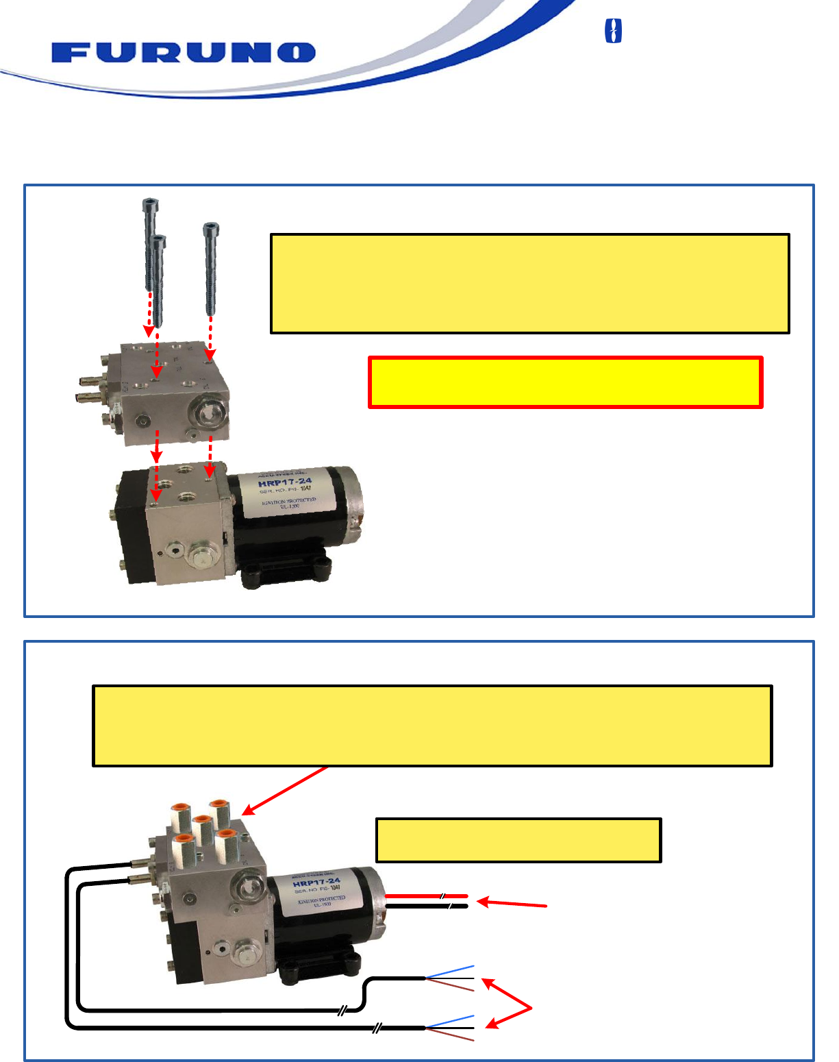
STEP 1
Use either a 19mm or 3/4" wrench to remove the 3 hydraulic
fittings from the top of the HRP Pump and discard. Five new
fittings are provided with the hardware kit.
STEP 2
Insert the 3 "O" rings from the hardware kit into the round recesses in the bottom of
the FPS-8 Power Steering Module. Apply a small amount of hydraulic fluid to the “O”
rings to hold them in place. Carefully assemble and tighten allen screws evenly,
ensuring that the o-rings are not pinched!!
Pre-Attachment Preparation
WARNING!!!
It is critical that this conversion only be performed on a VERY CLEAN work surface!
DIRT, DUST AND/OR OTHER CONTAMINANTS WILL DAMAGE THE PUMP AND
CAUSE IT TO FAIL!!!
WARNING!!!
It is critical that this conversion only be performed on a VERY CLEAN work surface!
DIRT, DUST AND/OR OTHER CONTAMINANTS WILL DAMAGE THE PUMP AND
CAUSE IT TO FAIL!!!
See compatible pump
models listed above
FURUNO U.S.A., INC.
Camas, WA
(360) 834-9300
www.furunousa.com
Denton, MD
(410) 413-4420
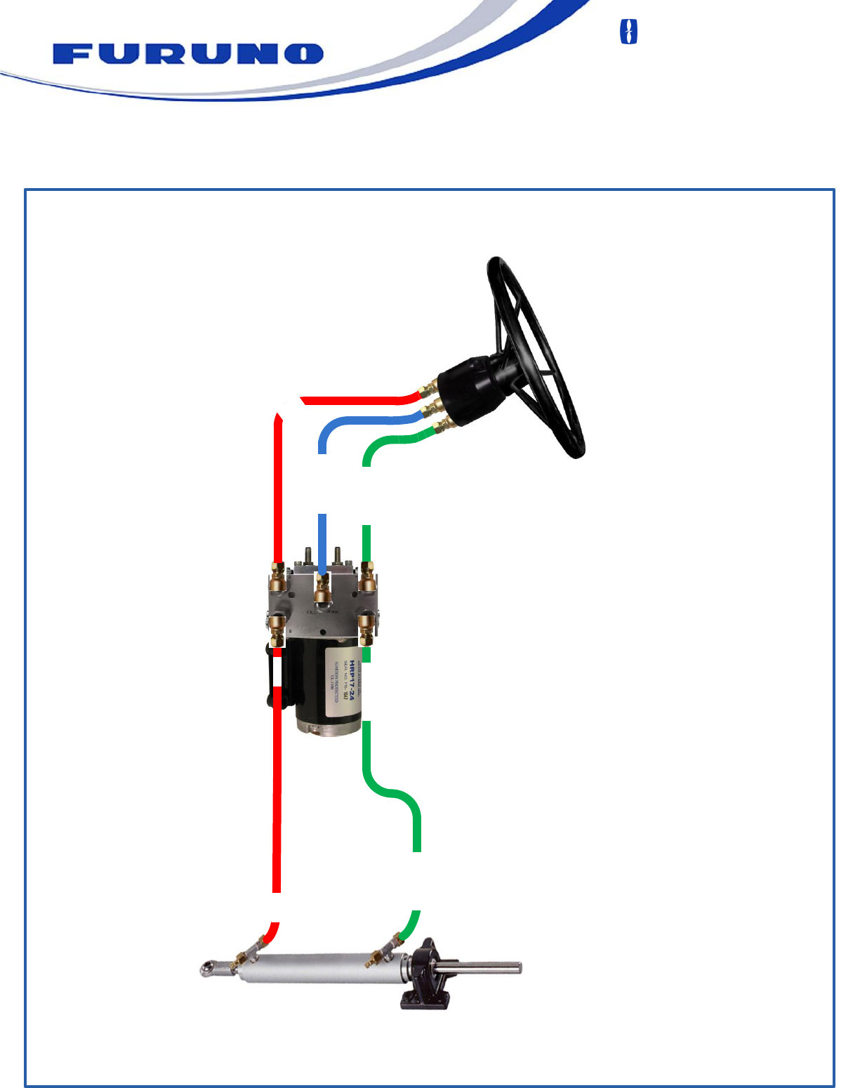
STEP 3
STEP 4
Align the 3 bolt holes in FPS-8 Power Steering Module with the 3 threaded
holes in the HRP Pump housing.
Screw in the 3 Allen-head bolts from the hardware pack. Tighten them
evenly with a 3/16" Allen wrench.
Insert the 5 hydraulic fittings from the hardware pack into the 5 threaded holes in the FPS-8 Power
Steering Module.
Please see the FPS-8 Installation Manual for more information regarding the hydraulic connections.
Make sure the "O" rings remain in place and do
not fall out or get pinched during assembly.
Connect wires per instructions in the
NavPilot 700 Installation Manual
Pump / motor wires to
TB2 in NavPilot
Processor
FPS-8 Sensor wires to
TB5 in Navpilot
Processor
Attaching the FPS8 to the HRP Pump
FURUNO U.S.A., INC.
Camas, WA
(360) 834-9300
www.furunousa.com
Denton, MD
(410) 413-4420
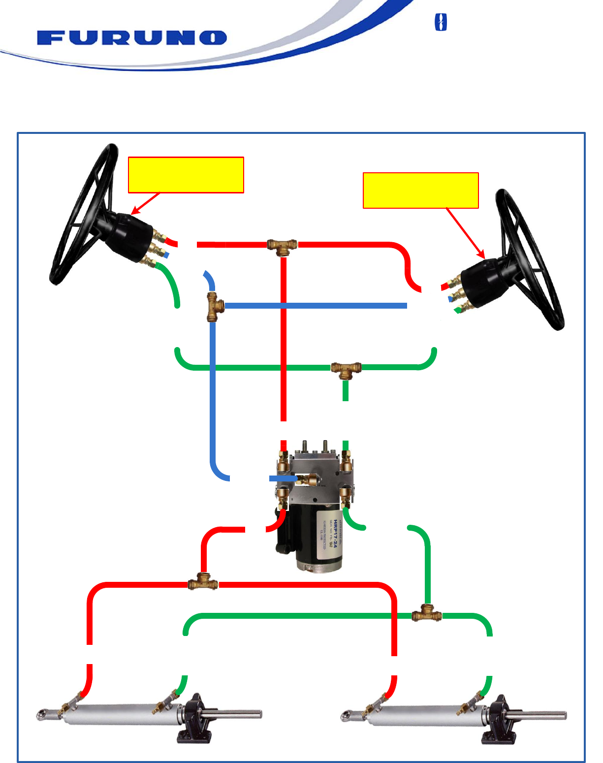
Hydraulic Diagram - Single Helm & Single Ram
NavPilot HRP Pump with FPS8
Power Steering Module
HELM
CYLINDER A
STARBOARD
HELM / TANK
PORT
STARBOARD
PORT
STARBOARD
PORT
FURUNO U.S.A., INC.
Camas, WA
(360) 834-9300
www.furunousa.com
Denton, MD
(410) 413-4420
Hydraulic Diagram - Dual Helm & Dual Cylinder
Upper Helm Station must
have a vented fill plug. Lower Helm Station must
have a non-vented fill plug.
UPPER
HELM B
LOWER
NavPilot HRP Pump with FPS8
Power Steering Module
HELM A
CYLINDER B CYLINDER A
PORT
PORT
PORT
PORT
STARBOARD
STARBOARD
HELM / TANK
STA
RBO
ARD
STARBOARD
STARBOARD
PORT
STARBOARD
HELM / TANK
HELM
TANK
/
PORT
FURUNO U.S.A., INC.
Camas, WA
(360) 834-9300
www.furunousa.com
Denton, MD
(410) 413-4420
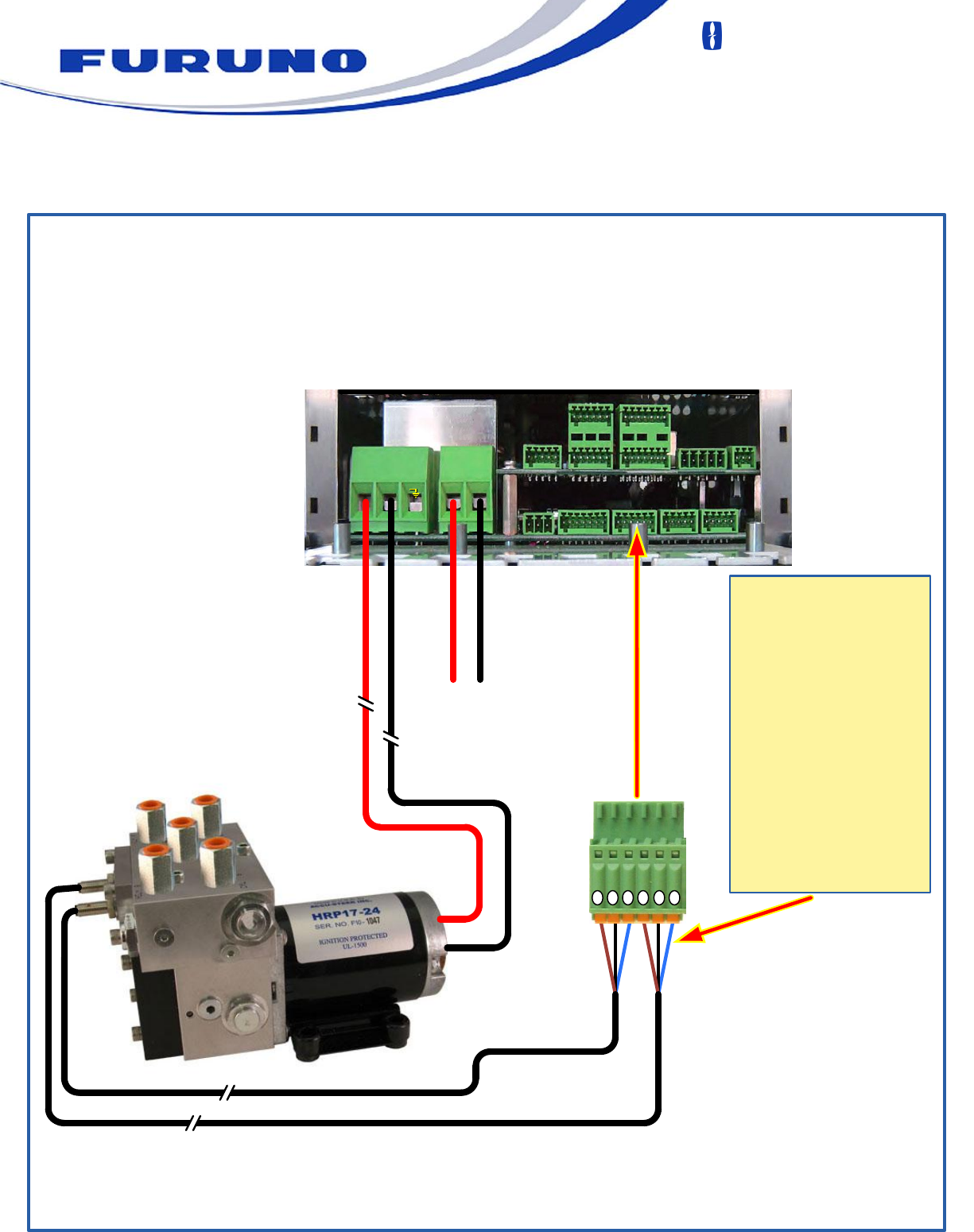
Electrical Connection Diagram
1 2 3 4 5 6
Motor /
Solenoid
+-TB5
Pin 1 = SW1 Brown
Pin 2 = SW1 Black
Pin 3 = SW1 Blue
Pin 4 = SW2 Brown
Pin 5 = SW2 Black
Pin 6 = SW2 Blue
Motor /
Solenoid
+-+-
+-
Power
Input
Power
Input
TB4
TB3
TB10 TB11 TB12
TB6 TB7
TB2 TB1
TB2 TB1
12 / 24 VDC
INPUT
NavPilot 700 / 711 / 720
Processor (FAP-7002)
TB13 TB8
To TB5
Each of the sensor
cables has the
same 3 wires. It
does not matter
which set of 3 go to
pins 1, 2 & 3 or 4, 5
& 6. It only matters
that the order of the
wires are as follows:
