Futaba FDK02TU COMMUNICATION SYSTEM LEAKY COAX User Manual users manual
Futaba Corporation COMMUNICATION SYSTEM LEAKY COAX users manual
UserManual.wiki
>
Futaba
>
FDK02TU User Manual
>
users manual
Contents
1.
users manual
2.
users manual statement
users manual
Navigation menu
Upload a User Manual
Namespaces
Wiki Guide
HTML
PDF
Info
Views
User Manual
Discussion / Help
Navigation
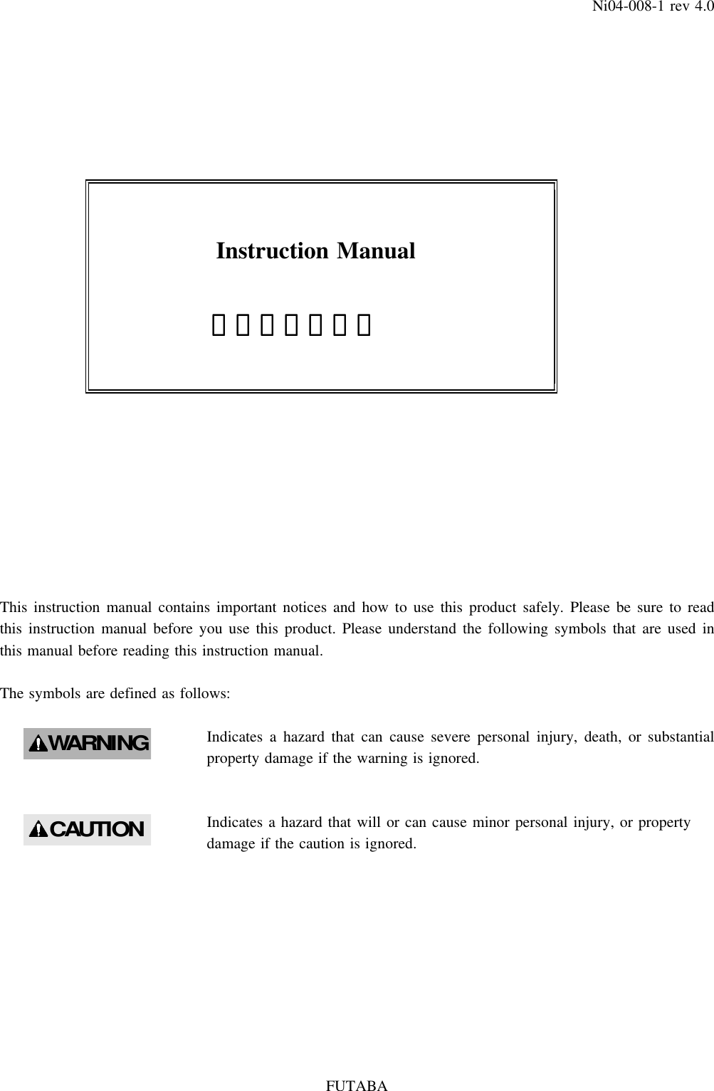
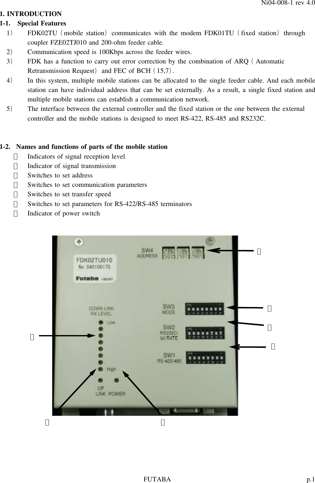
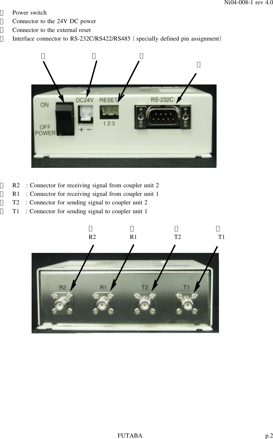
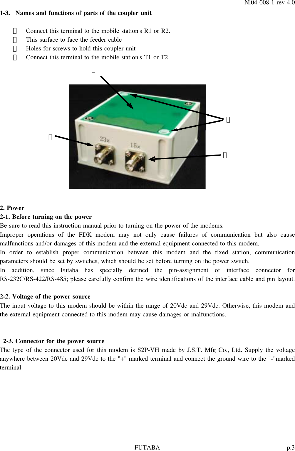
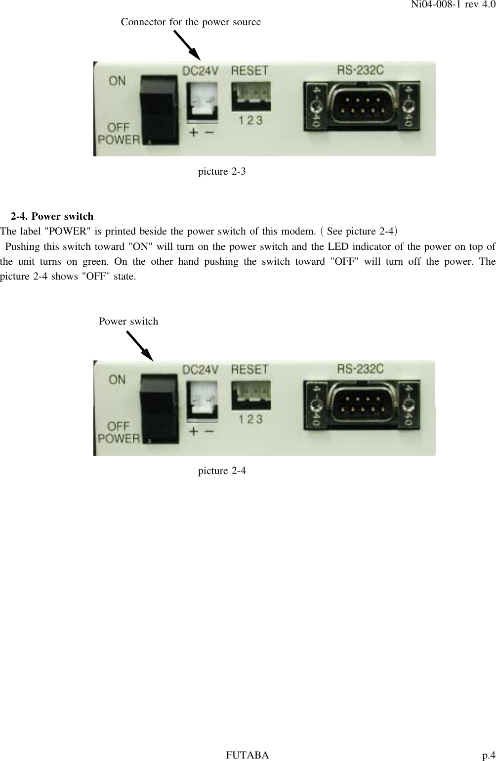
![p.9FUTABANi04-008-1 rev 4.0Table 5-3 SW2 DIP-8()Item bit ON OFFSet D-sub connector 1 Select RS-232C or RS-422/485 RS-422/485 RS-232C()wiring of RS-232C 2 1packet user data length Refer to table 4-434 ReservedCommon for 5 Transfer speedRS-422/485/232C 6 Refer to table 4-5.78 ReservedThe shadowed indicates the Ex-factory conditions.Table 5-4 Setting of 1 packet user data lengthSW2 NumberofuserdatabytesNo. bit3 bit2 BYTE[]1OFFOFF 82OFFON 163ONOFF 324ONON 64The shadowed indicates the Ex-factory conditions.Table 5-5 Setting of transfer speedSW2 Transfer speedNo. bit7 bit6 bit5 bps[]1 OFF OFF OFF 48002OFFOFFON 96003 OFF ON OFF 192004 OFF ON ON 384005 ON OFF OFF 576006 ON OFF ON reserve7 ON ON OFF 1152008 ON ON ON 115200The shadowed indicates the Ex-factory conditions.Table 5-6 SW3 DIP-8()Item bit content ON OFF1 Data length 7 82 Stop bit 2 1Communication parameters 3 Parity yes none4 Parity even or odd even odd5 Software flow control valid Not valid6 Multi-connection or single multi singleconnection with RS-422/485Add "CR" and "LF" to reception7 data and output it to the external add Not addI/F8 Output packets to all mobile output N o tstations and the host computer outputThe shadowed indicates the Ex-factory conditions.](https://usermanual.wiki/Futaba/FDK02TU.users-manual/User-Guide-451025-Page-13.png)
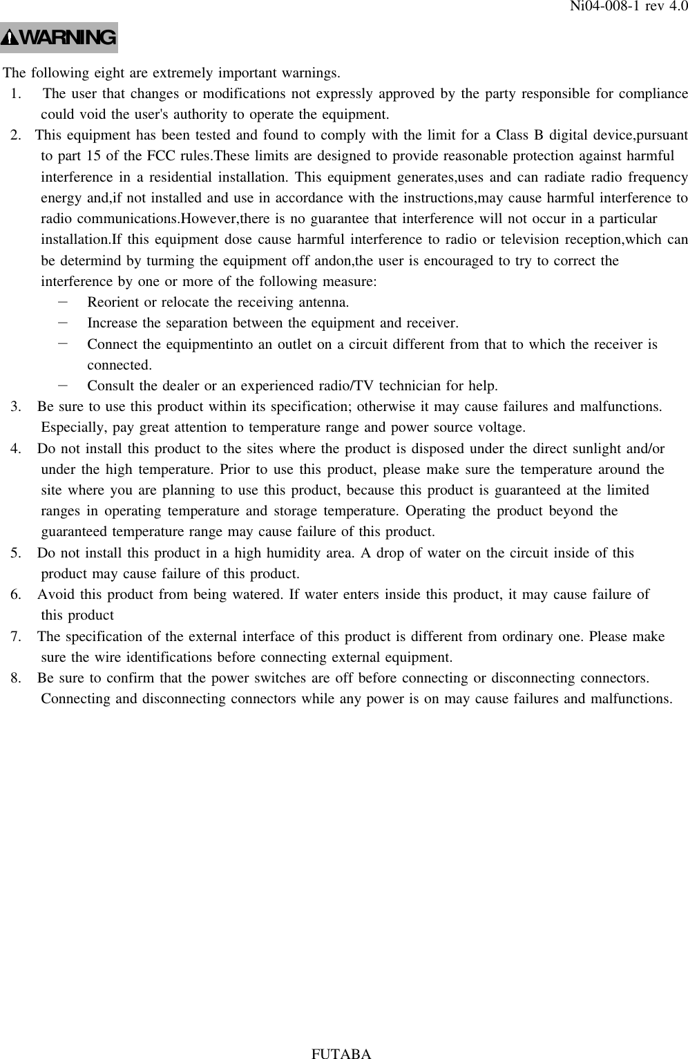
![p.10FUTABANi04-008-1 rev 4.0Table 5-7 SW4 3 sets of 16-step rotary switch()Item Effective value noteOwn address 400h to 9FFh Default value is 400h000h through 3FFh are prohibited.6. Communication commandInput and output between external control equipment and mobile stations are carried out by packet method.The data format of the packet method is either in the sequence of "@TXT address user data CR LF "()( )[][]or in the sequence of "@TBN address data length user data "()( )( )Binary data method is useful to avoid communication errors when a control code matches exactly a part of userdata.Text data @TXT address user data CR LF()( )[][]Address : ASCII code, hexadecimal 3-digits()For instance, 4 is "34h" in ASCII.Data : ASCII code, hexadecimalThe data length : Arbitrary but no more than 1024 bytes.[]CR : 0Dh in hexadecimal[]LF : 0Ah in hexadecimalExample : Sending "ABCDEFG" to a mobile station whose address is 400.@TXT400ABCDEFG CR LF[][]Binary data @TBN address data length user data()( )( )Address : ASCII code, hexadecimal 3-digitsData length : "001" to "400" 0 to 1024 bytes()The number of bytes should be expressed by hexadecimal 3-digits inASCII code.[][]CR LF : not necessaryIf data length is longer than predetermined data length, the surplus of the data will slide infront of the next instruction. Therefore "NG CR LF " may be returned to the data[][]sender.Example : Sending 7 bytes of binary data to a mobile station whose address is 400.@TBN400007 7 bytes of binary data()Taking into consideration the manual input through terminal software, the text data method can delete acharacter by recognizing backspace key while the binary data method treats backspace key as data.In the communication between the feeder cable and mobile stations, a packet is defined and transmitted as thenumber of user bytes that are set by bit2 and bit3 of the DIP SW2.In the case that transmission and reception of all the data is completed properly, the sender will output the](https://usermanual.wiki/Futaba/FDK02TU.users-manual/User-Guide-451025-Page-14.png)
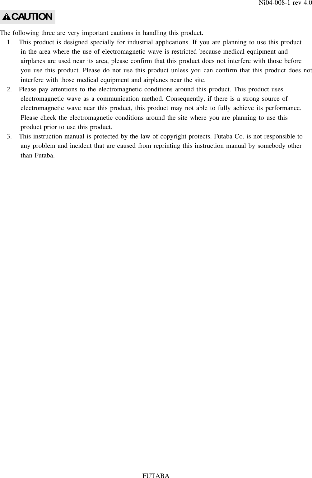
![p.11FUTABANi04-008-1 rev 4.0message "OK CR LF " after receiving ACK of the last packet.[][]On the other hand, the receiver will output the same character string that was sent from the sender from theheadfirst. In case of @TBN command, the receiver will output the data that is within the range determined bythe user data length, otherwise surplus of the data will not be outputted.In case of communication error, if ACK is not returned from the destination after repeating retransmission upto the preset number, the sender will stop sending data and output "NG CR LF " immediately after[][]detection of the end of input data.In case of failure while sending a packet due to communication error, the sender will output the partial datathat the sender could properly receive from the external interface of the receiver.7. Control commandControl commands are used for controlling the fixed station.Command tableNo. Command contentstring1FRQ Write or read frequency channel number2PNG Request response & read the reception intensity of the destination3SWR Read switch information4RST Reset software5COP Setting of the coupler or readout@FRQ : Write or read frequency channel number1 Input : @FRQpp CR LF)[][]pp : Input a number between 1 and 50 ASCII code or input nothing for pp.()()noteInputting a single digit is allowed for 1 through 9.Do not input space between "FRQ" and "pp".2 Processing : If there is no input for "pp", the current frequency channel number will be outputted.)Response messageFRQ = pp CR LF[][]()notepp : 01 to 50 ASCII code()Spaces are necessary in front of and afterwards of "=".: If a channel number is inputted in "pp", this modem will return "OK" message to the hostcomputer after changing the SRAM register and reassign the frequency number,.3 Frequency channel at the booting)At the booting this modem and resetting the software, the frequency channel is given by the settingbySW5onthecasetop.](https://usermanual.wiki/Futaba/FDK02TU.users-manual/User-Guide-451025-Page-15.png)
![p.12FUTABANi04-008-1 rev 4.0@PNG : Request response & read the reception intensity of the destination1 Input : @PNG CR LF)[][]2 Processing : Receiving this command, this modem returns as a response message the signal intensity)of the last packet that this modem has received.Response massageRSSI = nn CR LF[][]nn : Hexadecimal number of signal intensity in dBm[]@SWR : Read switch information1 Input : @SWR CR LF)[][]2 Processing : Receiving this command, this modem outputs information related to its switches of SW2)through SW5. SW1 has no function to send its information.SW2 : Binary, 8 digits 0: OFF, 1:ON BIT8 is in the far left.()SW3 : Binary, 8 digits 0: OFF, 1:ON BIT8 is in the far left.()SW4 : Hexadecimal, 2 digits The lower 2 digits of address()SW5 : Hexadecimal, 2 digitsIn case of the fixed station, this figure shows the setting condition of its channel switches.The most significant digit of the mobile station address corresponds to the rotary switch in the far rightof the SW5.@RST : Reset software1 Input : @RST CR LF)[][]2 Processing : Receiving this command, software will be reset.)This command restarts the exerciser program from the start address.Also the SRAM register will be reset to the condition when this modem was turned on.In addition, this command will initialize not only the software but also the hardware of this modem.It takes about 300ms.After the completion of initialization, a response message of "OK" will be returned to the hostcomputer.@COP : Setting of the coupler or readout valid only for mobile stations()1 Input : @COPp CR LF)[][]"p" should be 1 or 2 in ASCII code, or enter nothing.Do not input space between "COP" and "p".2 Processing : in case of no value for "p";)The current status of the coupler is read out.The message will be;COP = p CR LF[][]p=1or2inASCIIcodeA space code 0x20 will be added to either side of the "=".()](https://usermanual.wiki/Futaba/FDK02TU.users-manual/User-Guide-451025-Page-16.png)
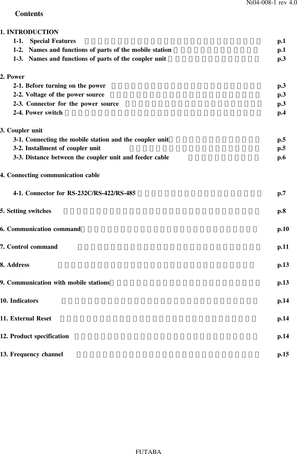
![p.1613. Frequency channelFrequency FrequencyChannel No. Down-link Up-link Channel No. Down-link Up-link[] [] [] []MHz MHz MHz MHz1 230.05 151.05 26 232.55 153.552 230.15 151.15 27 232.65 153.653 230.25 151.25 28 232.75 153.754 230.35 151.35 29 232.85 153.855 230.45 151.45 30 232.95 153.956 230.55 151.55 31 233.05 154.057 230.65 151.65 32 233.15 154.158 230.75 151.75 33 233.25 154.259 230.85 151.85 34 233.35 154.3510 230.95 151.95 35 233.45 154.4511 231.05 152.05 36 233.55 154.5512 231.15 152.15 37 233.65 154.6513 231.25 152.25 38 233.75 154.7514 231.35 152.35 39 233.85 154.8515 231.45 152.45 40 233.95 154.9516 231.55 152.55 41 234.05 155.0517 231.65 152.65 42 234.15 155.1518 231.75 152.75 43 234.25 155.2519 231.85 152.85 44 234.35 155.3520 231.95 152.95 45 234.45 155.4521 232.05 153.05 46 234.55 155.5522 232.15 153.15 47 234.65 155.6523 232.25 153.25 48 234.75 155.7524 232.35 153.35 49 234.85 155.8525 232.45 153.45 50 234.95 155.95FUTABANi04-008-1 rev 4.0](https://usermanual.wiki/Futaba/FDK02TU.users-manual/User-Guide-451025-Page-20.png)