Futaba FDK02TU COMMUNICATION SYSTEM LEAKY COAX User Manual users manual
Futaba Corporation COMMUNICATION SYSTEM LEAKY COAX users manual
Futaba >
Contents
- 1. users manual
- 2. users manual statement
users manual

Instruction Manual
FDK02TU
FDK02TUFDK02TU
FDK02TU
This instruction manual contains important notices and how to use this product safely. Please be sure to read
this instruction manual before you use this product. Please understand the following symbols that are used in
this manual before reading this instruction manual.
The symbols are defined as follows:
Indicates a hazard that can cause severe personal injury, death, or substantial
property damage if the warning is ignored.
Indicates a hazard that will or can cause minor personal injury, or property
damage if the caution is ignored.
WARNING
CAUTION
FUTABA
Ni04-008-1 rev 4.0

FUTABA
Ni04-008-1 rev 4.0
The following eight are extremely important warnings.
1. The user that changes or modifications not expressly approved by the party responsible for compliance
could void the user's authority to operate the equipment.
2. This equipment has been tested and found to comply with the limit for a Class B digital device,pursuant
to part 15 of the FCC rules.These limits are designed to provide reasonable protection against harmful
interference in a residential installation. This equipment generates,uses and can radiate radio frequency
energy and,if not installed and use in accordance with the instructions,may cause harmful interference to
radio communications.However,there is no guarantee that interference will not occur in a particular
installation.If this equipment dose cause harmful interference to radio or television reception,which can
be determind by turming the equipment off andon,the user is encouraged to try to correct the
interference by one or more of the following measure:
−Reorient or relocate the receiving antenna.
−Increase the separation between the equipment and receiver.
−Connect the equipmentinto an outlet on a circuit different from that to which the receiver is
connected.
−Consult the dealer or an experienced radio/TV technician for help.
3. Be sure to use this product within its specification; otherwise it may cause failures and malfunctions.
Especially, pay great attention to temperature range and power source voltage.
4. Do not install this product to the sites where the product is disposed under the direct sunlight and/or
under the high temperature. Prior to use this product, please make sure the temperature around the
site where you are planning to use this product, because this product is guaranteed at the limited
ranges in operating temperature and storage temperature. Operating the product beyond the
guaranteed temperature range may cause failure of this product.
5. Do not install this product in a high humidity area. A drop of water on the circuit inside of this
product may cause failure of this product.
6. Avoid this product from being watered. If water enters inside this product, it may cause failure of
this product
7. The specification of the external interface of this product is different from ordinary one. Please make
sure the wire identifications before connecting external equipment.
8. Be sure to confirm that the power switches are off before connecting or disconnecting connectors.
Connecting and disconnecting connectors while any power is on may cause failures and malfunctions.
WARNI NG

FUTABA
Ni04-008-1 rev 4.0
The following three are very important cautions in handling this product.
1. This product is designed specially for industrial applications. If you are planning to use this product
in the area where the use of electromagnetic wave is restricted because medical equipment and
airplanes are used near its area, please confirm that this product does not interfere with those before
you use this product. Please do not use this product unless you can confirm that this product does not
interfere with those medical equipment and airplanes near the site.
2. Please pay attentions to the electromagnetic conditions around this product. This product uses
electromagnetic wave as a communication method. Consequently, if there is a strong source of
electromagnetic wave near this product, this product may not able to fully achieve its performance.
Please check the electromagnetic conditions around the site where you are planning to use this
product prior to use this product.
3. This instruction manual is protected by the law of copyright protects. Futaba Co. is not responsible to
any problem and incident that are caused from reprinting this instruction manual by somebody other
than Futaba.
CAUTION

FUTABA
Ni04-008-1 rev 4.0
Contents
1. INTRODUCTION
1-1. Special Features p.1
・・・・・・・・・・・・・・・・・・・・・・・・・・・
1-2. Names and functions of parts of the mobile station p.1
・・・・・・・・・・・・・
1-3. Names and functions of parts of the coupler unit p.3
・・・・・・・・・・・・・・
2. Power
2-1. Before turning on the power p.3
・・・・・・・・・・・・・・・・・・・・・・・
2-2. Voltage of the power source p.3
・・・・・・・・・・・・・・・・・・・・・・・
2-3. Connector for the power source p.3
・・・・・・・・・・・・・・・・・・・・・
2-4. Power switch p.4
・・・・・・・・・・・・・・・・・・・・・・・・・・・・・・
3. Coupler unit
3-1. Connecting the mobile station and the coupler unit p.5
・・・・・・・・・・・・・・
3-2. Installment of coupler unit p.5
・・・・・・・・・・・・・・・・・・・・
3-3. Distance between the coupler unit and feeder cable p.6
・・・・・・・・・・・
4. Connecting communication cable
4-1. Connector for RS-232C/RS-422/RS-485 p.7
・・・・・・・・・・・・・・・・・・・
5. Setting switches p.8
・・・・・・・・・・・・・・・・・・・・・・・・・・・・・・
6. Communication command p.10
・・・・・・・・・・・・・・・・・・・・・・・・・・・
7. Control command p.11
・・・・・・・・・・・・・・・・・・・・・・・・・・・・
8. Address p.13
・・・・・・・・・・・・・・・・・・・・・・・・・・・・・・
9. Communication with mobile stations p.13
・・・・・・・・・・・・・・・・・・・・・・・
10. Indicators p.14
・・・・・・・・・・・・・・・・・・・・・・・・・・・・・・
11. External Reset p.14
・・・・・・・・・・・・・・・・・・・・・・・・・・・・・・
12. Product specification p.14
・・・・・・・・・・・・・・・・・・・・・・・・・・・・
13. Frequency channel p.15
・・・・・・・・・・・・・・・・・・・・・・・・・・・・
p.1FUTABA
Ni04-008-1 rev 4.0
1. INTRODUCTION
1-1. Special Features
1 FDK02TU mobile station communicates with the modem FDK01TU fixed station through
)() ()
coupler FZE02TJ010 and 200-ohm feeder cable.
2 Communication speed is 100Kbps across the feeder wires.
)
3 FDK has a function to carry out error correction by the combination of ARQ Automatic
) (
Retransmission Request and FEC of BCH 15,7 .
)()
4 In this system, multiple mobile stations can be allocated to the single feeder cable. And each mobile
)
station can have individual address that can be set externally. As a result, a single fixed station and
multiple mobile stations can establish a communication network.
5 The interface between the external controller and the fixed station or the one between the external
)
controller and the mobile stations is designed to meet RS-422, RS-485 and RS232C.
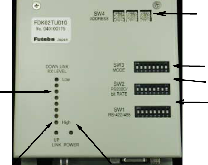
1-2. Names and functions of parts of the mobile station
①Indicators of signal reception level
②Indicator of signal transmission
③Switches to set address
④Switches to set communication parameters
⑤Switches to set transfer speed
⑥Switches to set parameters for RS-422/RS-485 terminators
⑦Indicator of power switch
③
④
⑤
①⑥
②⑦
p.2FUTABA
Ni04-008-1 rev 4.0
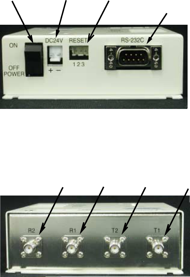
⑧Power switch
⑨Connector to the 24V DC power
⑩Connector to the external reset
⑪()
Interface connector to RS-232C/RS422/RS485 specially defined pin assignment
⑧⑨⑩ ⑪
⑫R2 : Connector for receiving signal from coupler unit 2
⑬R1 : Connector for receiving signal from coupler unit 1
⑭T2 : Connector for sending signal to coupler unit 2
⑮T1 : Connector for sending signal to coupler unit 1
⑫⑬ ⑭⑮
R2 R1 T2 T1
p.3FUTABA
Ni04-008-1 rev 4.0
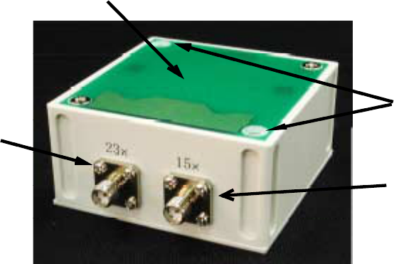
1-3. Names and functions of parts of the coupler unit
⑯Connect this terminal to the mobile station's R1 or R2.
⑰This surface to face the feeder cable
⑱Holes for screws to hold this coupler unit
⑲Connect this terminal to the mobile station's T1 or T2.
⑰
⑱
⑯
⑲
2. Power
2-1. Before turning on the power
Be sure to read this instruction manual prior to turning on the power of the modems.
Improper operations of the FDK modem may not only cause failures of communication but also cause
malfunctions and/or damages of this modem and the external equipment connected to this modem.
In order to establish proper communication between this modem and the fixed station, communication
parameters should be set by switches, which should be set before turning on the power switch.
In addition, since Futaba has specially defined the pin-assignment of interface connector for
RS-232C/RS-422/RS-485; please carefully confirm the wire identifications of the interface cable and pin layout.
2-2. Voltage of the power source
The input voltage to this modem should be within the range of 20Vdc and 29Vdc. Otherwise, this modem and
the external equipment connected to this modem may cause damages or malfunctions.
2-3. Connector for the power source
The type of the connector used for this modem is S2P-VH made by J.S.T. Mfg Co., Ltd. Supply the voltage
anywhere between 20Vdc and 29Vdc to the "+" marked terminal and connect the ground wire to the "-"marked
terminal.
p.4FUTABA
Ni04-008-1 rev 4.0
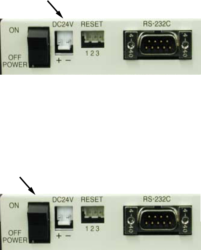
Connector for the power source
picture 2-3
2-4. Power switch
The label "POWER" is printed beside the power switch of this modem. See picture 2-4
()
Pushing this switch toward "ON" will turn on the power switch and the LED indicator of the power on top of
the unit turns on green. On the other hand pushing the switch toward "OFF" will turn off the power. The
picture 2-4 shows "OFF" state.
Power switch
picture 2-4
p.5FUTABA
Ni04-008-1 rev 4.0
3. Coupler unit
3-1. Connecting the mobile station and the coupler unit
A mobile station has four 50-ohm impedance SMA connectors. The connector type used here is;
Connector : MKT TAISEI CO., LTD. CON1718-BN 4 pieces
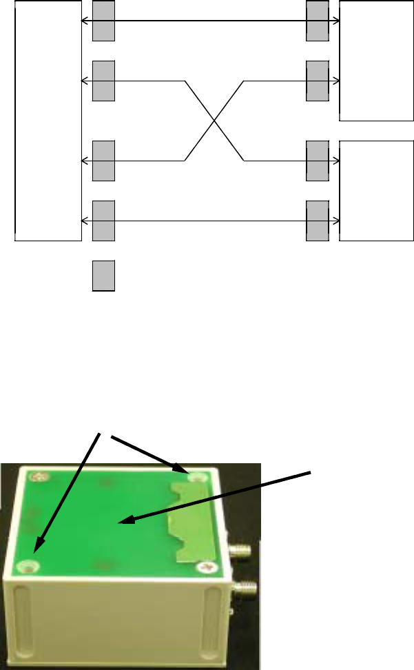
Two connecters are for transmission and the other two are for reception.
Connections between a mobile station and the two units of couplers are shown in figure 3-1. T1 and R1 of a
mobile station should be connected to one unit of two couplers. T2 and R2 of the mobile station should be
connected to the other like figure 3-1.
mobile station
rear panel
T1 15x
coupler 1
T2 23x
R1 15x
coupler 2
R2 23x
ferrite core NEC TOKIN CO. ESD-SR-12 100-ohm
≧
()
100MHz
3-2. Installment of coupler unit
①Holes for screws to hold this coupler unit
Use two ISO M3 screws to hold the unit.
②This surface to face the feeder cable
①
②
p.6FUTABA
Ni04-008-1 rev 4.0
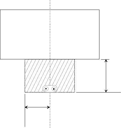
3-3. Distance between the coupler unit and feeder cable
Install coupler units and feeder cables in the shadowed area in the figure 3-3, otherwise communication cannot
be carried out.
Figure 3-3
coupler unit
Y= 2 0mm
X=15mm
p.7FUTABA
Ni04-008-1 rev 4.0
4. Connecting communication cable
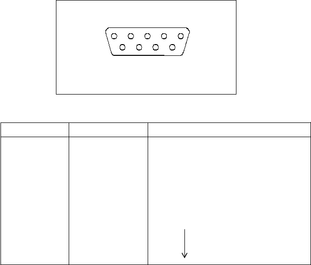
4-1. Connector for RS-232C/RS-422/RS-485
Connector model: Hirose Electric Co., Ltd. RDED-9P-LN 4-40 50
()()
Please select one out of RS-232C, RS-422 and RS-485.
PIN No. Signal name note
1NC
2TD RS-232C transfer data
3RD RS-232C recieve data
4NC
5GND Signal ground.
6/
RD+ RS422 RS485
7RD-
8TD+
9TD-
RS-232C uses the pins 2, 3 and 5.
RS-422 and RS-485 use the pins 5 through 9.
SW 1 on top of the unit can select either RS-422 or RS-485 and can either connect the termination resisters or
disconnect them.
SW2 is the common switch for RS-232C, RS-422 and RS485 to set parameters of communication speed and so
on.
Please refer to the next section for further detail.
12345
6789
D-sub 9PIN
p.8FUTABA
Ni04-008-1 rev 4.0
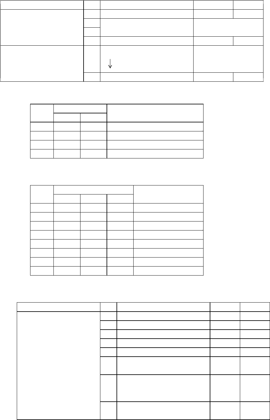
5. Setting switches
The functions of the dipswitches and a rotary switch are follows:
SW1 8bit DIP-SW Set parameters of RS-422/485
SW2 8bit DIP-SW Set transfer speed
SW3 8bit DIP-SW Set communication parameters
SW4 3 sets of 16-step rotary switch Own station address
table 5-1
Table 5-2 SW1 DIP-8
()
Item bit ON OFF
内容
Set D-sub connector 1 Connect/disconnect TD+ and RD+ connected open
Set termination 2 Connect/disconnect TD- and RD- connected open
resisters RS-422/485 3 Connect/disconnect the resister connected open
()
between TD+ and TD-
4 Connect/disconnect the resister connected open
between RD+ and RD-
5 Connect/disconnect the pull-up connected open
resister to RD+
6 Connect/disconnect the pull-down connected open
resister to RD-
7 Set parameters of RS-422/485 OFF during Normally
reception driverRS-422/485 transmission ON
8 Reserved
The shadowed indicates the Ex-factory conditions
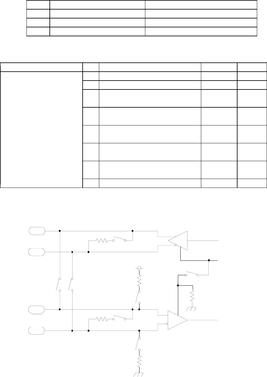
internal
TD
internal
RD
TD+
TD-
RD+
RD-
Figure 5-1 RS-422/485 interface circuitry
LTC491
LTC491
100Ω
100Ω
1kΩ
1kΩ
bit1 bit2
bit3
bit4
bit5
bit6
DE
1kΩ
bit7
p.9FUTABA
Ni04-008-1 rev 4.0
Table 5-3 SW2 DIP-8
()
Item bit ON OFF
Set D-sub connector 1 Select RS-232C or RS-422/485 RS-422/485 RS-232C
()
wiring of RS-232C 2 1packet user data length Refer to table 4-4
3
4 Reserved
Common for 5 Transfer speed
RS-422/485/232C 6 Refer to table 4-5.
7
8 Reserved
The shadowed indicates the Ex-factory conditions.
Table 5-4 Setting of 1 packet user data length
SW2 Numberofuserdatabytes
No. bit3 bit2 BYTE
[]
1OFFOFF 8
2OFFON 16
3ONOFF 32
4ONON 64
The shadowed indicates the Ex-factory conditions.
Table 5-5 Setting of transfer speed
SW2 Transfer speed
No. bit7 bit6 bit5 bps
[]
1 OFF OFF OFF 4800
2OFFOFFON 9600
3 OFF ON OFF 19200
4 OFF ON ON 38400
5 ON OFF OFF 57600
6 ON OFF ON reserve
7 ON ON OFF 115200
8 ON ON ON 115200
The shadowed indicates the Ex-factory conditions.
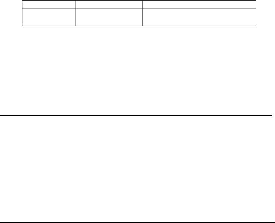
Table 5-6 SW3 DIP-8
()
Item bit content ON OFF
1 Data length 7 8
2 Stop bit 2 1
Communication parameters 3 Parity yes none
4 Parity even or odd even odd
5 Software flow control valid Not valid
6 Multi-connection or single multi single
connection with RS-422/485
Add "CR" and "LF" to reception
7 data and output it to the external add Not add
I/F
8 Output packets to all mobile output N o t
stations and the host computer output
The shadowed indicates the Ex-factory conditions.
p.10FUTABA
Ni04-008-1 rev 4.0
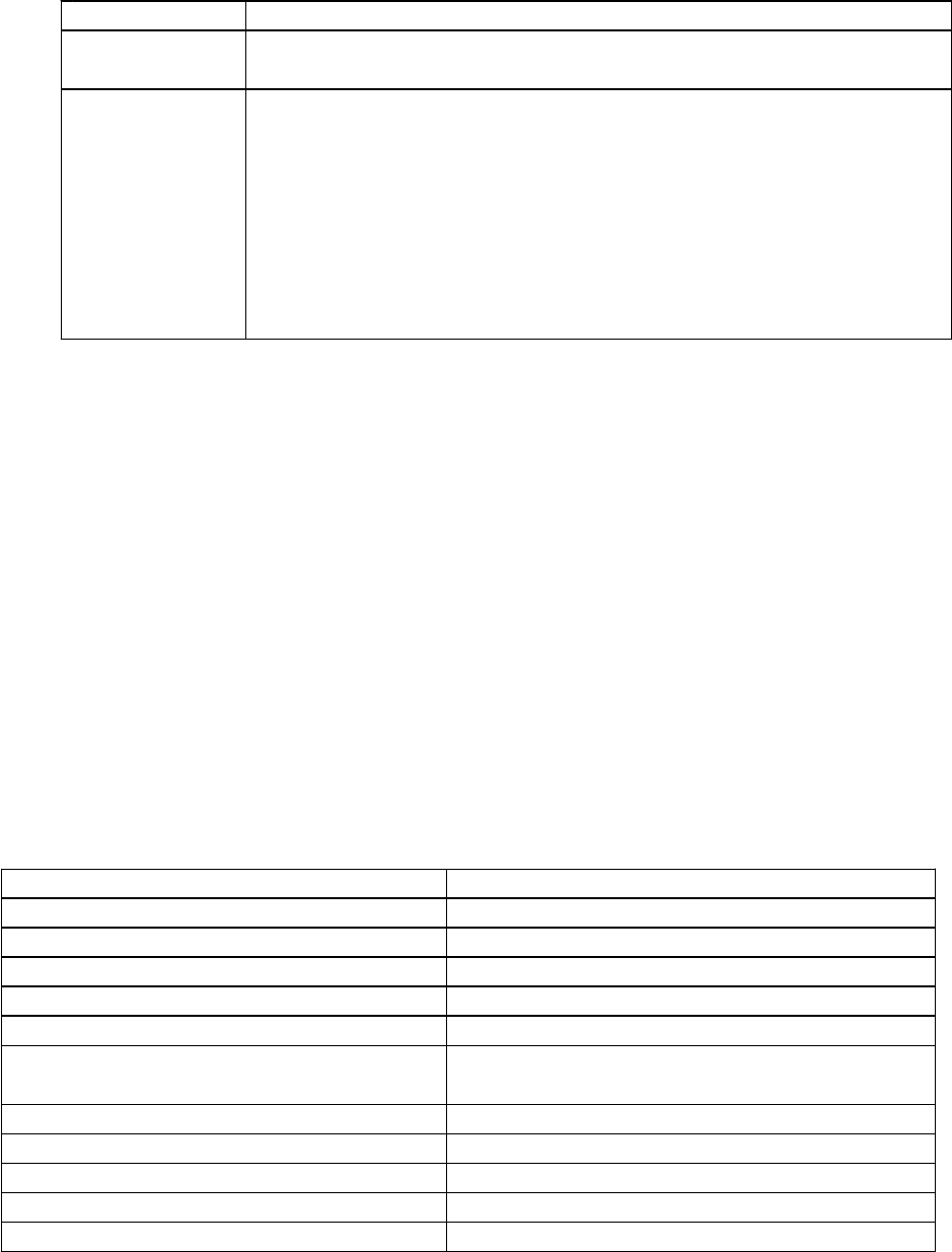
Table 5-7 SW4 3 sets of 16-step rotary switch
()
Item Effective value note
Own address 400h to 9FFh Default value is 400h
000h through 3FFh are prohibited.
6. Communication command
Input and output between external control equipment and mobile stations are carried out by packet method.
The data format of the packet method is either in the sequence of "@TXT address user data CR LF "
()( )[][]
or in the sequence of "@TBN address data length user data "
()( )( )
Binary data method is useful to avoid communication errors when a control code matches exactly a part of user
data.
Text data @TXT address user data CR LF
()( )[][]
Address : ASCII code, hexadecimal 3-digits
()
For instance, 4 is "34h" in ASCII.
Data : ASCII code, hexadecimal
The data length : Arbitrary but no more than 1024 bytes.
[]
CR : 0Dh in hexadecimal
[]
LF : 0Ah in hexadecimal
Example : Sending "ABCDEFG" to a mobile station whose address is 400.
@TXT400ABCDEFG CR LF
[][]
Binary data @TBN address data length user data
()( )( )
Address : ASCII code, hexadecimal 3-digits
Data length : "001" to "400" 0 to 1024 bytes
()
The number of bytes should be expressed by hexadecimal 3-digits in
ASCII code.
[][]
CR LF : not necessary
If data length is longer than predetermined data length, the surplus of the data will slide in
front of the next instruction. Therefore "NG CR LF " may be returned to the data
[][]
sender.
Example : Sending 7 bytes of binary data to a mobile station whose address is 400.
@TBN400007 7 bytes of binary data
()
Taking into consideration the manual input through terminal software, the text data method can delete a
character by recognizing backspace key while the binary data method treats backspace key as data.
In the communication between the feeder cable and mobile stations, a packet is defined and transmitted as the
number of user bytes that are set by bit2 and bit3 of the DIP SW2.
In the case that transmission and reception of all the data is completed properly, the sender will output the

p.11FUTABA
Ni04-008-1 rev 4.0
message "OK CR LF " after receiving ACK of the last packet.
[][]
On the other hand, the receiver will output the same character string that was sent from the sender from the
headfirst. In case of @TBN command, the receiver will output the data that is within the range determined by
the user data length, otherwise surplus of the data will not be outputted.
In case of communication error, if ACK is not returned from the destination after repeating retransmission up
to the preset number, the sender will stop sending data and output "NG CR LF " immediately after
[][]
detection of the end of input data.
In case of failure while sending a packet due to communication error, the sender will output the partial data
that the sender could properly receive from the external interface of the receiver.
7. Control command
Control commands are used for controlling the fixed station.
Command table
No. Command content
string
1FRQ Write or read frequency channel number
2PNG Request response & read the reception intensity of the destination
3SWR Read switch information
4RST Reset software
5COP Setting of the coupler or readout
@FRQ : Write or read frequency channel number
1 Input : @FRQpp CR LF
)[][]
pp : Input a number between 1 and 50 ASCII code or input nothing for pp.
()
()
note
Inputting a single digit is allowed for 1 through 9.
Do not input space between "FRQ" and "pp".
2 Processing : If there is no input for "pp", the current frequency channel number will be outputted.
)
Response message
FRQ = pp CR LF
[][]
()
note
pp : 01 to 50 ASCII code
()
Spaces are necessary in front of and afterwards of "=".
: If a channel number is inputted in "pp", this modem will return "OK" message to the host
computer after changing the SRAM register and reassign the frequency number,.
3 Frequency channel at the booting
)
At the booting this modem and resetting the software, the frequency channel is given by the setting
bySW5onthecasetop.

p.12FUTABA
Ni04-008-1 rev 4.0
@PNG : Request response & read the reception intensity of the destination
1 Input : @PNG CR LF
)[][]
2 Processing : Receiving this command, this modem returns as a response message the signal intensity
)
of the last packet that this modem has received.
Response massage
RSSI = nn CR LF
[][]
nn : Hexadecimal number of signal intensity in dBm
[]
@SWR : Read switch information
1 Input : @SWR CR LF
)[][]
2 Processing : Receiving this command, this modem outputs information related to its switches of SW2
)
through SW5. SW1 has no function to send its information.
SW2 : Binary, 8 digits 0: OFF, 1:ON BIT8 is in the far left.
()
SW3 : Binary, 8 digits 0: OFF, 1:ON BIT8 is in the far left.
()
SW4 : Hexadecimal, 2 digits The lower 2 digits of address
()
SW5 : Hexadecimal, 2 digits
In case of the fixed station, this figure shows the setting condition of its channel switches.
The most significant digit of the mobile station address corresponds to the rotary switch in the far right
of the SW5.
@RST : Reset software
1 Input : @RST CR LF
)[][]
2 Processing : Receiving this command, software will be reset.
)
This command restarts the exerciser program from the start address.
Also the SRAM register will be reset to the condition when this modem was turned on.
In addition, this command will initialize not only the software but also the hardware of this modem.
It takes about 300ms.
After the completion of initialization, a response message of "OK" will be returned to the host
computer.
@COP : Setting of the coupler or readout valid only for mobile stations
()
1 Input : @COPp CR LF
)[][]
"p" should be 1 or 2 in ASCII code, or enter nothing.
Do not input space between "COP" and "p".
2 Processing : in case of no value for "p";
)
The current status of the coupler is read out.
The message will be;
COP = p CR LF
[][]
p=1or2inASCIIcode
A space code 0x20 will be added to either side of the "=".
()
p.13FUTABA
Ni04-008-1 rev 4.0
: In case that some value is inputted for "p":
Coupler units will be switched.
3 Default setting
)
COP = 1
4 Timing of command execution
)
Receiving a command from external I/F, the mobile terminal will carry out the command and return
its end message immediately after the disconnection of the coupler is completed. This command will
be carried out regardless of the communication status on the feeder.
8. Address
The effective addresses for mobile stations are from 400 trough 9FF.
Use rotary switch SW4 for setting.
Set the address at "001" when sending data to the fixed station from mobile stations.
The address setting of the fixed station is required only for the host computer to send control command to
the specific one of the fixed stations that is connected in multi-drop fashion. No specific address is
necessary in case sending data from mobile stations, because there exits only one fixed station.
9. Communication with mobile stations
Communication procedure an example
()
①Set parameters of fixed station, and make it effective to communicate with mobile stations.
②Connect to the power source.
③( )
Connect the external interface One of RS-232C, RS422 and RS485
④Connect to the matching/distributing unit.
(②④ )
The order between and can be changed freely.
⑤Turn on the fixed station and mobile stations.
()
The order to turn on the powers is free.
⑥Wait more than 1 second and then set frequency channel.
After receiving a response of "OK", forward to the next step.
⑦Send command/data in format of @TXT or @TBN.
If "OK" is returned, the communication is completed.
If "NG" is returned, possible reasons of the failure are insufficient signal strength and improper settings of
communication cable, switches and frequencies.
Send @PNG command and read the value of RSSI. If the value is 57 or lager, please confirm the setting
condition again.
If "OK" is returned, it is possible to continue communication by repeating .
⑦
p.14FUTABA
Ni04-008-1 rev 4.0
10. Indicators
POWER When green LED is on, the power is on.
DOWN LINK When green LED is off, there is no packet.
When green LED is on, packets have been sent to feeder cables.
UP LINK Combinations of eight LEDs indicate the levels of the signal intensity.
RX LEVEL 2 Red LEDs ON : or =-90dBm
<
2 Red and 1 Orange LEDs : or =-85dBm
<
2 Red and 2 Orange LEDs : or =-80dBm
<
2 Red, 2 Orange 1 Green LEDs : or =-75dBm
<
2 Red, 2 Orange 2 Green LEDs : or =-70dBm
<
2 Red, 2 Orange 3 Green LEDs : or =-65dBm
<
2 Red, 2 Orange 4 Green LEDs : -65dBm
>
11. External Reset
The following connector is equipped with this modem so that the hardware of this modem can be reset
externally.
Connector type : J.S.T. Mfg Co., Ltd S3B-XH-SM3-TB
In order to reset this modem externally, short #2 and #3 pins of the RESET connector in the picture 11-1
more than 10ms: then disconnect them.
One of the terminals is connected to the internal power source and the other is to the ground line through
560ohm resister respectively.
12. Product specification
12-1. communication characteristics of feeder cable
項目 内 容
Up link frequency band transmitter
() 151 MHz 156 MHz
∼
Down link frequency band receiver
() 230 MHz 235 MHz
∼
Frequency band per channel 100 kHz
Interval between frequency channels 100 kHz
Number of frequency channels 50
Emission power FCC part15 ClassB
≦μ
43.5dB V/m at 3m
Reception signal intensity -87dBm at 100kbs, BER
(≦
10-
4
)
Addresses for mobile modems own address addresses
()
400h 9FFh 1536
∼( )
Communication speed 100 kbps
Communication mode Full-Duplex Packet mode
Error detection/correction Combination of ARQ and BCH

p.15FUTABA
Ni04-008-1 rev 4.0
12-2. external I/F specification
Item Notes
Connector D-sub 9 pins
Communication standards RS-232C, RS-422, RS-485 Specially defined pin
(
assignments are used for this product.)
Communication speed 4800bps to 115.2kbps
Communication method Full-Duplex Packet mode
RS-232C,RS-422
RS-485 Full-Duplex Packet mode
others Connect/disconnect signal linesConnect/disconnect
terminator resistance for RS-422 and RS485
12-3. mobile station's general specification
Item Notes
Voltage of the power source DC 20V to 29V
Consumption power ≦3W
Outer dimensions 102 D x 116 W x 35 H mm() ( ) ()
Weight ≦550g
Material of the chassis Iron 1 mm thickness
()
Surface treatment of the chassis and color Surface treatment : Coating on bonded steelColor
: DIC 546 1/2 Dainippon Ink
()
Operating temperature range -10C to +50C
Storage temperature range -20C to +70C
Operating humidity rage 35%RH to 95%RH under no condensation
()
Storage humidity range 35%RH to 95%RH under no condensation
()
Anti-vibration The product should survive the following
vibration test;
Vibration amplitude : 3.5mm
Frequency : 10Hz
2 hours for back and forth
2 hours for left and right
4 hours for up and down
Anti-shock The product should survive the following shock
test; Acceleration : 500 m/s2
3 times along with 3 axis,
total 9 times500 m/s2
Anti-electro static Apply following high voltageInput/output
terminals
: 1kV contact discharge Chassis
±( )
: 5kV non-contact discharge
±( )
There should be no malfunction after test.
Chassis
: 10kV non-contact discharge
±( )
There should be no damage after test.The test
follows JASO-D-001-94 5.8 A-2,B-2,C-2
()

p.16
13. Frequency channel
Frequency Frequency
Channel No. Down-link Up-link Channel No. Down-link Up-link
[] [] [] []
MHz MHz MHz MHz
1 230.05 151.05 26 232.55 153.55
2 230.15 151.15 27 232.65 153.65
3 230.25 151.25 28 232.75 153.75
4 230.35 151.35 29 232.85 153.85
5 230.45 151.45 30 232.95 153.95
6 230.55 151.55 31 233.05 154.05
7 230.65 151.65 32 233.15 154.15
8 230.75 151.75 33 233.25 154.25
9 230.85 151.85 34 233.35 154.35
10 230.95 151.95 35 233.45 154.45
11 231.05 152.05 36 233.55 154.55
12 231.15 152.15 37 233.65 154.65
13 231.25 152.25 38 233.75 154.75
14 231.35 152.35 39 233.85 154.85
15 231.45 152.45 40 233.95 154.95
16 231.55 152.55 41 234.05 155.05
17 231.65 152.65 42 234.15 155.15
18 231.75 152.75 43 234.25 155.25
19 231.85 152.85 44 234.35 155.35
20 231.95 152.95 45 234.45 155.45
21 232.05 153.05 46 234.55 155.55
22 232.15 153.15 47 234.65 155.65
23 232.25 153.25 48 234.75 155.75
24 232.35 153.35 49 234.85 155.85
25 232.45 153.45 50 234.95 155.95
FUTABA
Ni04-008-1 rev 4.0