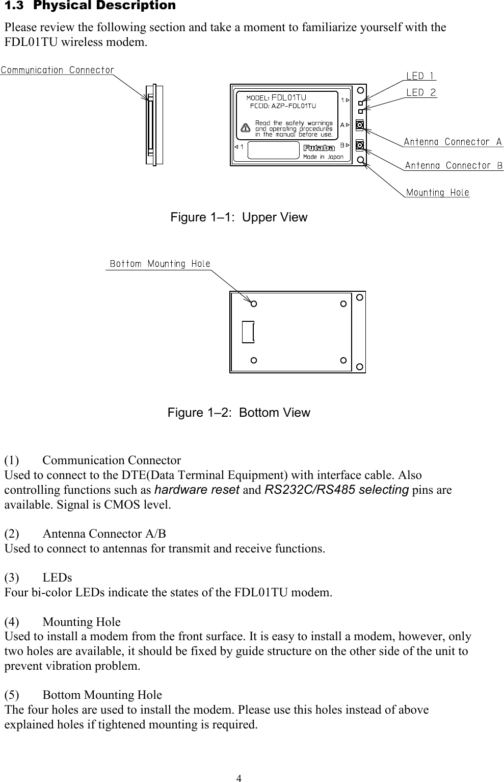
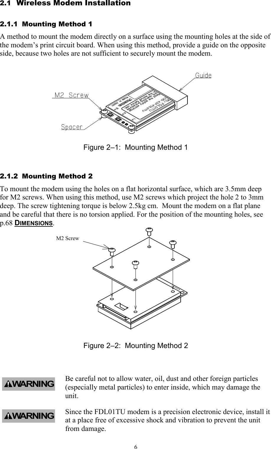
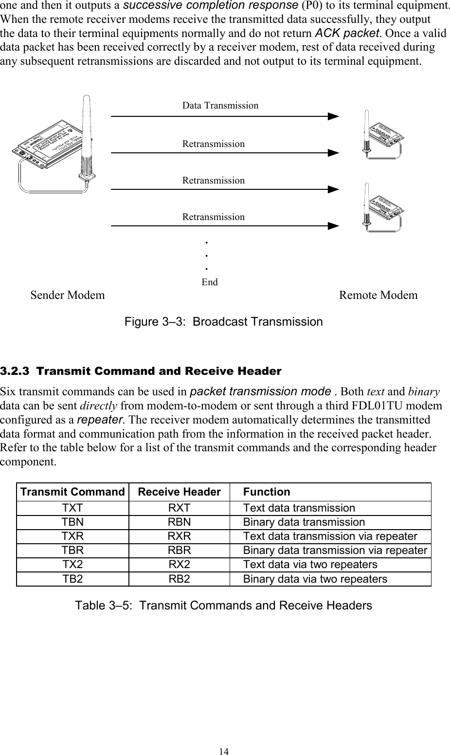
Futaba FDL01TU Wireless Modem with Serial Interface User Manual
Futaba Corporation Wireless Modem with Serial Interface Users Manual
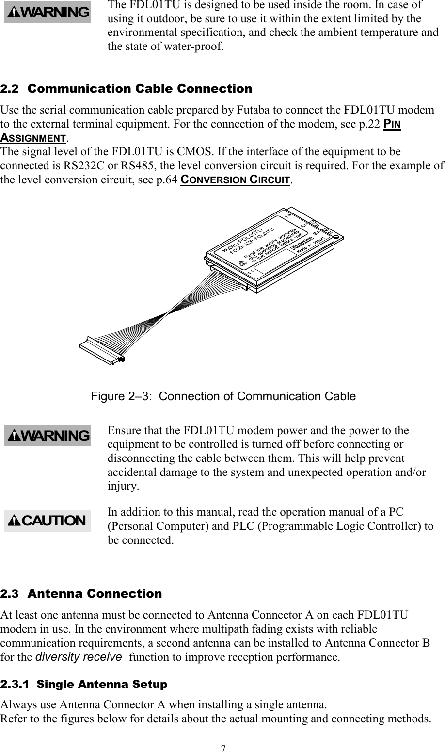
UserManual.wiki
>
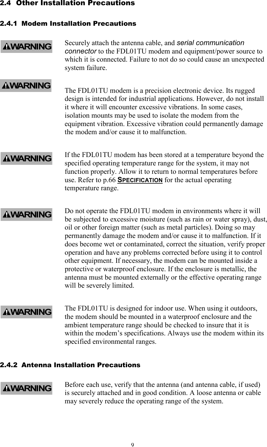
Futaba
>
FDL01TU User Manual
Users Manual
Navigation menu
Upload a User Manual
Namespaces
Wiki Guide
HTML
PDF
Info
Views
User Manual
Discussion / Help
Navigation


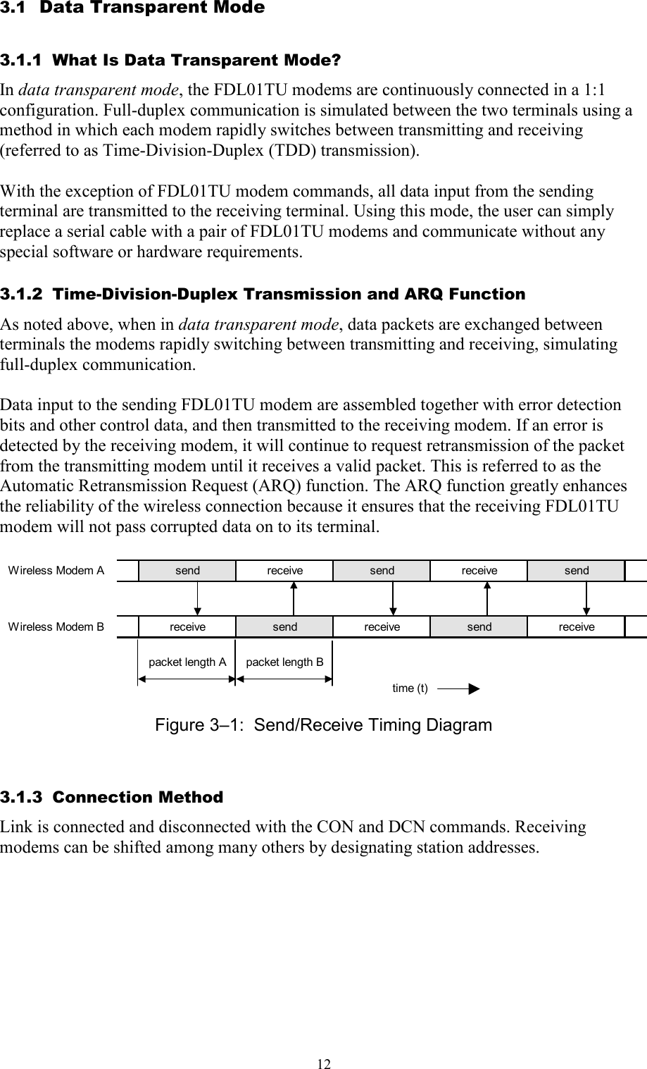
![15The following list shows each command’s syntax as issued at the sender terminal equipment and the response displayed at the receiver terminal equipment when the packet is received. 1. Direct Text Data Transmission transmit: @TXT [destination address]{source address}[message] receive: RXT [source address][message] CR/LF 2. Direct Binary Data Transmission transmit: @TBN[destination address]{source address}[message length][message] CR/LF receive: RBN [source address][message length][message] CR/LF 3. Text Data Transmission through Repeater transmit: @TXR [repeater address][destination address]{source address} [message] CR/LF receive: RXR [repeater address][source address][message] CR/LF 4. Binary Data Transmission through Repeater transmit: @TBR [repeater address][destination address]{source address} [message length][message] CR/LF receive: RBR [repeater address][source address][message length][message] CR/LF where {source address} is optional, used in RS485 mode set by serial communication cable 12 pin. The following list defines the parameters and symbols used in the commands above: @ = command header CR/LF = carriage return + line feed destination address = address of modem to receive the message (000 to 239) source address = address of modem sent the message (000 to 239) repeater address = address of the repeater modem (000 to 239) message length = number of bytes in message message = information data (255 bytes or less) In the text data transmission, the message is considered to be terminated when the CR/LF code appears in it. No data after that will be transmitted. When the CR/LF code contains in a message, use the binary data transmission command. CAUTION](https://usermanual.wiki/Futaba/FDL01TU/User-Guide-595584-Page-29.png)
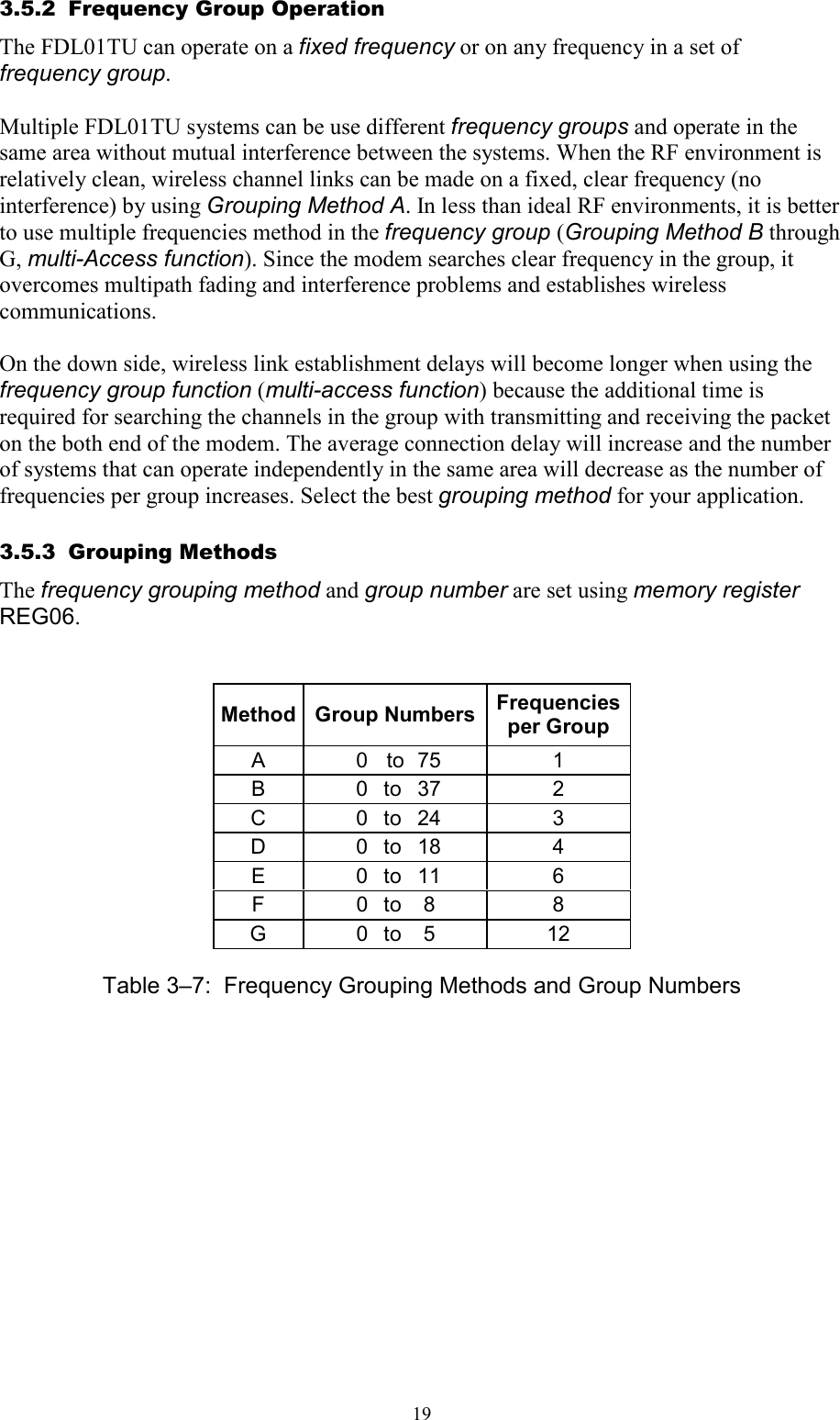

![29REG00: Local Station Address [default value: 000] • Sets the local station address. Valid values are 000 to 999. • This value is inserted in the “source address” field in the transmitted packet header. • If the address check function is enabled (REG18) in the receiving modem, the modem can receive the packet which header contains destination address information identical to REG00. REG01: Local Station Group Address [default value: 240] • Sets the local station global address of the modem. Valid values are 240 to 254. • When plural modems are connected by RS485 multi-dropping topology, commands can be issued to multiple modems simultaneously by setting all connected modems to the same group address. This is the group addressing. • This group addressing allows to handle multiple multi-dropped modems as if they were one modem. REG02: Destination Address [default value: 000] • This address is used in the data transpalent mode and headerless stream mode. • Valid values are 000 to A23(1023). REG03: Reserved [default value: F0H] • The FDL01TU does not use this register. Keep the default value as it is. REG04: ID Code 1 [default value: 00H] • Used with ID code 2 (REG05), set the ID code. Valid values are 000 to 255. Together with ID code 2, up to 65535 ID codes can be set. • The ID code identifies the group of the modems works in the same group. The ID code is used to prevent erroneous connection with other systems and for communication security. • Before transmission, radio data packets are scrambled using a pseudo-random data sequence generated with this ID code as the seed. During reception, the original data is restored by de-scrambling it with the pseudo-random data sequence. The modems with different ID codes cannot communicate with each other. REG05: ID Code 2 [default value: 00H] • Used with ID code 1 (REG04), set the ID code. Valid values are 000 to 255. Together with ID code 1, up to 65535 ID codes can be set. • In case plural modems are used as a single system, always set the same ID code for all modems and repeaters.](https://usermanual.wiki/Futaba/FDL01TU/User-Guide-595584-Page-43.png)
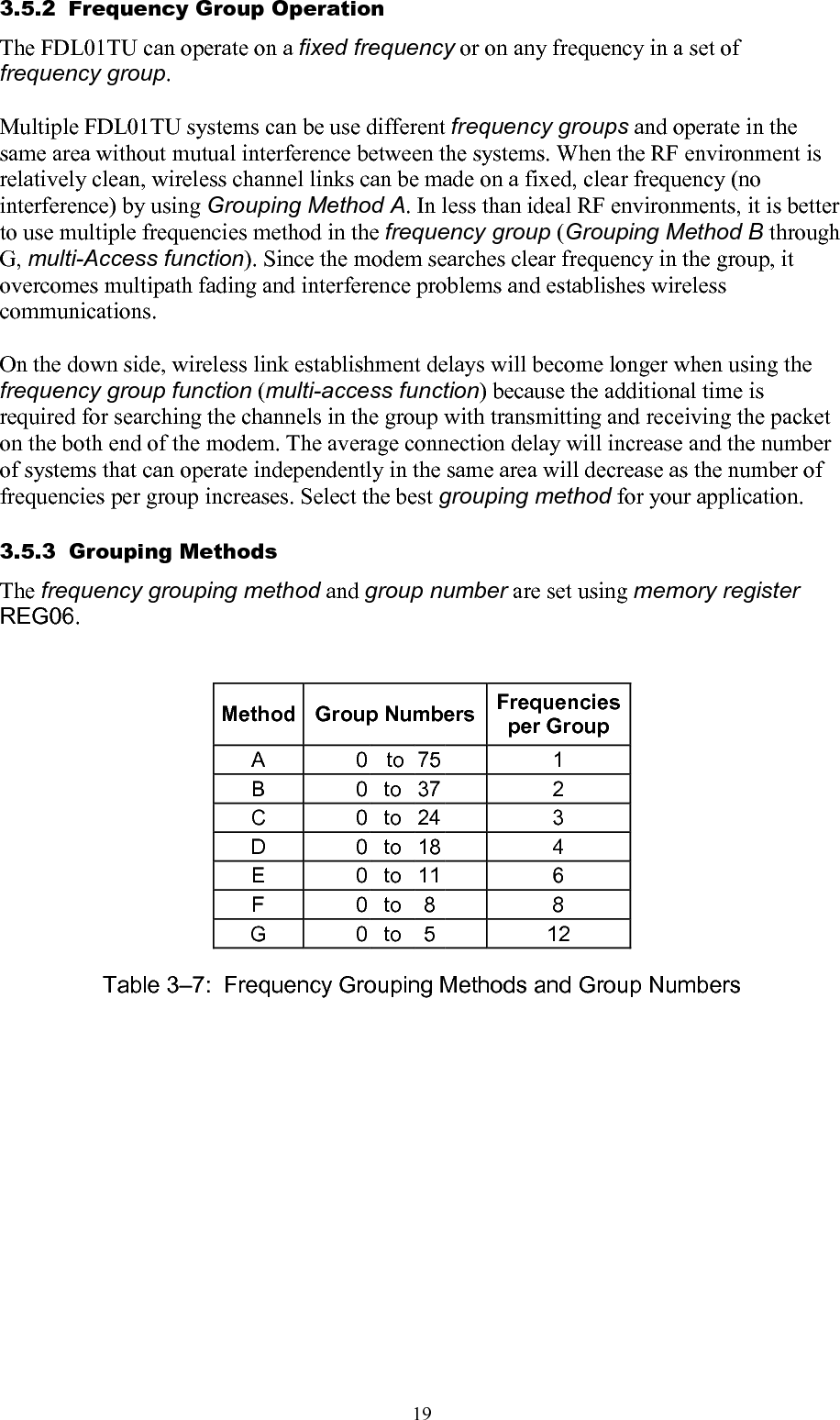
![30REG06: Frequency Group [default value:C00] • Refer to p.18 FREQUENCY GROUPING in Section 3, for a detailed description of the frequency operation modes. Method Group Numbers Frequencies per Group A 0 to 75 1 B 0 to 37 2 C 0 to 24 3 D 0 to 18 4 E 0 to 11 6 F 0 to 8 8 G 0 to 5 12 Table 5–2: Grouping of Frequency REG07: RS485 Packet Interval [default value: 05H] • In the packet transmission mode with the RS485 mode is used, sets the interval between response and/or received data which output from the modem to RS485 line. • Be able to set 0 to 254 ms at increment of 1 ms. 255ms is not allowed. The default value is 5 ms. • Set this interval to a larger value than the receiving interval set by REG14. • Suitable setting of this interval avoids the data collision possibility of RS485 line. REG08: Repeater 1 Address [default value: A00] • When a repeater is used, set the repeater1 address to pass through. REG09: Repeater 2 Address [default value: A00] • When second repeater is used, set the repeater2 address to pass through. REG10: Command Header [default value: 40H] • Sets the character that identifies the start of a command. • The default is character “@” (40H). • When this character is input from the terminal equipment after no character is received for the command recognition interval (REG15) or longer, subsequent input character is recognized as a command for the modem.](https://usermanual.wiki/Futaba/FDL01TU/User-Guide-595584-Page-44.png)
![31REG11: Retransmission Count [default value: 32H] • Sets the maximum number of packet retransmission attempts. Valid values are 000 to 255. • When retransmission exceeds the retransmission count (retransmission count plus one), the modem outputs an error response to the terminal equipment. REG12: Roaming Threshold [default value: 50H] • At the time to set the frequency roaming (REG19:bit 2 is 1), set the receiving strength threshold of the radio beacon which starts scanning frequency. • Set the value of the desired radio beacon strength threshold represented in dBm excluding the minus sign, e.g., set to “080” to search the next master station when the radio beacon strength becomes below –80 dBm. REG13: Buffer Data Timeout [default value: 1EH] • Valid values are 000 to 255, representing seconds in 1 s increments. REG14: Command Input Timeout [default value: 32H] • Sets the character input timeout interval for command input. It is used as the timeout between the command header and the character following it and between each character of the command. • At the timeout, the modem operation transits from command-input-state to data-wait-state. • Valid values are 000 to 255, representing tenths of seconds in 0.1 second increments. (Set an integer value equal to ten times the number of seconds desired.) • A setting of 000 disables this timeout function REG15: Command Recognition Interval [default value: 00H] • When a message data contains a command header character (in case of binary data or data in two-byte Chinese characters), data following the command header character will be interpreted as a command, the message does not transmit properly. • Sets the necessary vacant duration time interval to discriminate between ordinary data character and a command header character. Input a command after a longer interval than time interval setting. • Valid values are 0.1 to 25.4 sec., representing tenths of seconds in 0.1 second increments. (Set an integer value equal to ten times the number of seconds desired.) • When set to 000, the command header is recognized at any time, and when set to 255, all command header character are ignored.](https://usermanual.wiki/Futaba/FDL01TU/User-Guide-595584-Page-45.png)
![32REG16: Terminator 1 [default value: 0DH] • Set an arbitrary 1 byte terminator. In case of a 2-byte terminator, set the first byte character of the terminator. REG17: Terminator 2 [default value: 0AH] • Set another arbitrary 1 byte terminator. In case of a 2-byte terminator, set the last character of the terminator . REG18: Communication Setting 1 [default value: 8CH] Bits 7 – 6: Protocol bit 7 bit 6 Setting 0 0 Data transpalent mode 0 1 Reserved 1 0 Packet transmission mode 1 1 Headerless stream mode Table 5–7: Protocol Bits 5: Reserved • The FDL01TU does not use this register. Keep the default value as it is. Bit 4 Transmission format 0 transmit in the text form (default value) 1 transmit in the binary form Table 7–4 Transmission format • Selects the transmission format. When data are transmitted to the destination station which is set to the normal packet transmission mode, output text format (RXT, RBN) from the receiver modem (destination station) differs depend on this setting. • This setting does not effect in the receiver modem set as headerless stream mode. Bits 3 – 2 Terminator Setting bit 3 bit 2 setting 0 0 two kinds of arbitrary 1 byte code (REG16, REG17) 0 1 arbitrary 1 byte code (REG16) + a wild card (any character) 1 0 arbitrary 2 byte code (REG16 + REG17) 1 1 carriage return (CR) + line feed (LF) (default value) Table 7–5 Terminator setting](https://usermanual.wiki/Futaba/FDL01TU/User-Guide-595584-Page-46.png)
![33• Sets the terminator to identify the breakpoint of a packet. The modem transmits data considering this character as the breakpoint of a packet. • In case of using an arbitrary terminator, set it to REG16 and 17. Bit 1: Source address check 0 Inhibit source address checking (default value) 1 Activate source address checking Table 5–4: Source Address Check Settings • When the source address checking is active and the source address in the received packet header does not match the destination address setting (REG02), the data is discarded (data cannot be received). Bit 0: Destination address check 0 Inhibit destination address checking on receipt (default) 1 Activate destination address checking on receipt Table 5–5: Destination address check • When the destination address checking is active and the destination address in the received packet header does not match the received modem’s local station address (REG00), the data is discarded (data cannot be received). REG19: Communication Setting 2 [default value: 00H] Bit 7: Reserved • The FDL01TU does not use this register. Keep the default value as it is. Bit 6: Diversity Reception 0 Disable diversity reception (default value) 1 Enable diversity reception Table 5–6: Diversity Reception Settings • Enable/disable diversity reception. • To enable diversity reception, set this bit to 1. • Enabling diversity reception with only one antenna connected may degrade the reception performance. Bit 5: Broadcast Transmission Reception 0 Enable broadcast transmission reception (default value) 1 Disable broadcast transmission reception Table 5–7: Broadcast Reception Settings](https://usermanual.wiki/Futaba/FDL01TU/User-Guide-595584-Page-47.png)
![35REG20: Serial Interface Setting 1 [default value: 05H] Bit 7: Data Length 0 8 bit data bytes (default value) 1 7 bit data bytes Table 5–13: Data Length Settings Bit 6: Parity Bit 0 No parity bit (default value) 1 Parity bit Table 5–14: Parity Settings Bit 5: Even/Odd Parity 0 Even parity (default value) 1 Odd parity Table 5–15: Odd/Even Parity Settings • Invalid when bit 6 is set to 0, without parity. Bit 4: Stop Bit 0 1 stop bit (default value) 1 2 stop bits Table 5–16: Stop Bit Settings Bits 3 – 0: Baud rate setting Bit 3 Bit 2 Bit 1 Bit 0 Setting 0 0 0 0 300 bps 0 0 0 1 600 bps 0 0 1 0 1200 bps 0 0 1 1 2400 bps 0 1 0 0 4800 bps 0 1 0 1 9600 bps (default) 0 1 1 0 19200 bps 0 1 1 1 38400 bps 1 0 0 0 Reserved 1 0 0 1 Reserved 1 0 1 0 Reserved 1 0 1 1 Reserved 1 1 0 0 57600 bps 1 1 0 1 115200 bps 1 1 1 0 230400 bps 1 1 1 1 Reserved Table 5–17: Baud Rate](https://usermanual.wiki/Futaba/FDL01TU/User-Guide-595584-Page-49.png)
![36REG21: Serial Interface Setting 2 [default value: 09H] Bits 7 – 4: Reserved • The FDL01TU does not use this register. Keep the default value as it is. Bit 4: Command Header 0 Use REG 10 character 1 Use Break signal Table 5–16: Command Header Bit 1: Flow Control 0 Software flow control (default value) 1 Hardware flow control Table 5–18 Software/Hardware Flow Control Settings • Selects the flow control method. This setting must match the connected terminal equipment’s setting. • Hardware flow control uses the two control lines RTS and CTS. When using with the RS485 interface, be sure to set to 0. • Software flow control uses XON and XOFF codes. Bit 0: Flow Control 2 0 disable flow control 1 enable flow control Table 5–31: Flow Control 2 Settings • Enable or disable flow control between the terminal and FDL01TU modem connected through the RS-232C serial interface. • This function should normally be enabled, otherwise buffer overflow can occur and data may be lost. REG22: Serial Interface Setting 3 [default value: 00H] Bit 7: Enable and Disable Reception 0 Enable reception at the initial state (default value) 1 Disable reception at the initial state Table 5–19: Enable/Disable Reception • The initial state is in reception enable. Depending on an usage of the modem, the initial state of the modem may be better in the reception disable state. In such a case, use this setting.](https://usermanual.wiki/Futaba/FDL01TU/User-Guide-595584-Page-50.png)
![37• Issue the REN command to enable reception. Bit 6: Reserved • The FDL01TU does not use this register. Keep the default value as it is. Bits 5 – 4: DCD (Data Carrier Detect) Bit 5 Bit 4 Setting 0 0 Ignore DCD input; DCD output always ON (default value) 0 1 Ignore DCD input; DCD output ON at connection, OFF at disconnection 1 0 Remote modem’s DCD (IN) is transferred to local modem DCD (OUT). (DCD Output = OFF at reset state) 1 1 Remote modem’s DCD (IN) is transferred to local modem DCD (OUT) (DCD Output = ON at reset state) Table 5–20: DCD Settings Bits 3 – 2: DTR/DSR Bit 3 Bit 2 Setting 0 0 Ignore DTR input; DSR output always ON (default value) 0 1 Ignore DTR input; DSR output ON at connection, OFF at disconnection 1 0 Remote modem DTR is transferred on local modem CTS (CTS = OFF at reset state) 1 1 Remote DTR is transferred on local modem CTS (CTS = ON at reset state) Table 5–21: DTR/DSR Control Settings Bits 1 – 0: Reserved • The FDL01TU does not use this register. Keep the default value as it is. REG23: Serial Interface Setting 4 [default value: 00H] Bit 7 : reserved • The FDL01TU does not use this register. Keep the default value as it is. Bit 6 : Transmission buffer clear 0 Data of the transmission buffer is kept after disconnection (default value) 1 Transmission buffer is cleared when the link is disconnected. Table 5–38 Transmission buffer clear • Determine to clear or not to clear data stored in the transmission buffer in the data transparent mode when the link is reconnected. Bit 5 : reserved • The FDL01TU does not use this register. Keep the default value as it is.](https://usermanual.wiki/Futaba/FDL01TU/User-Guide-595584-Page-51.png)
![40REG24: Special Mode Settings [default value: C0H] Bit 7 : reserved • The FDL01TU does not use this register. Keep the default value as it is. Bit 6: Transmission trigger (Headerless stream mode) 0 Need trigger even if data number exceeds 255 bytes(default value) 1 Transmit without trigger when the data number exceeds 255 bytes Table 5–26: Transmission trigger setting • Sets the trigger mode of the Headerles stream mode. Bit 5 – 2: reserved • The FDL01TU does not use this register. Keep the default value as it is. Bits 1 – 0: Reception protocol Bit 1 Bit 0 Setting 0 0 Receive with the setting of REG18 bit7 to bit6(default value) 0 1 Receive with the packet transmission mode 1 0 Receive with the headerless stream mode 1 1 Receive with the protokol of the received packet Table 5–21: Reception protocol REG25: Special Mode Settings 2 [default value: 40H] Bit 7 – 3: reserved • The FDL01TU does not use this register. Keep the default value as it is. Bit 2: Group address settings 0 Normal group address (240 to 254)(default value) 1 Extended group address (1000 to 1023) Table 5–29: Group address setting Bit 1: Address response 0 No response the address when the link is connected or disconnected (default value) 1 Response the destination address when the link is connected or disconnected. Table 5–29: Address response](https://usermanual.wiki/Futaba/FDL01TU/User-Guide-595584-Page-54.png)
![41Bit 0: Route finding 0 According to the memory registers (default value) 1 Trace the received packet. Table 5–29: Settings of the route REG26: Data input timeout [default value: 00H] • Sets the vacant duration time interval to recognize as the end of the message data input in the headerless stream mode. REG27: Reserved [default value: 00H] • The FDL01TU does not use this register. Keep the default value as it is.](https://usermanual.wiki/Futaba/FDL01TU/User-Guide-595584-Page-55.png)

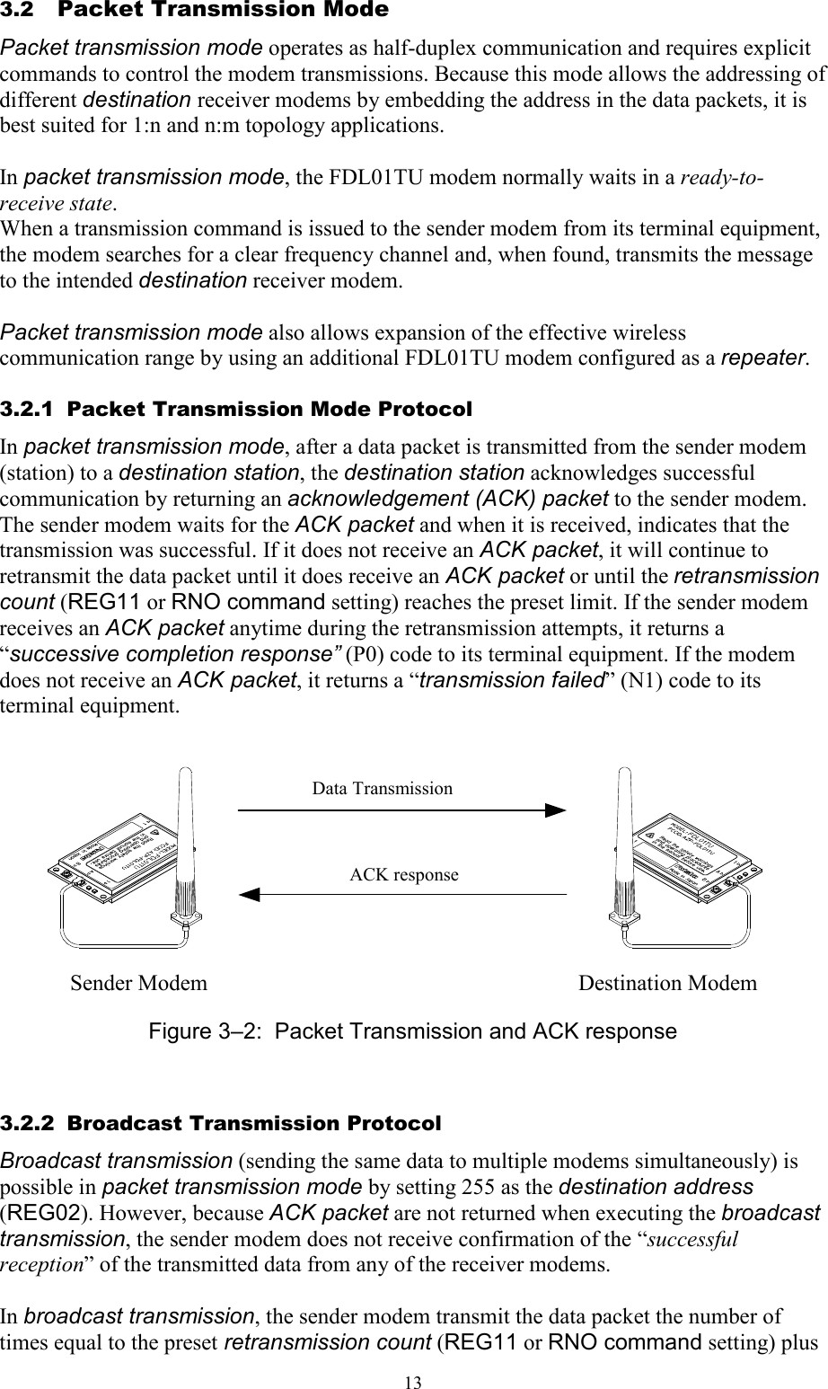
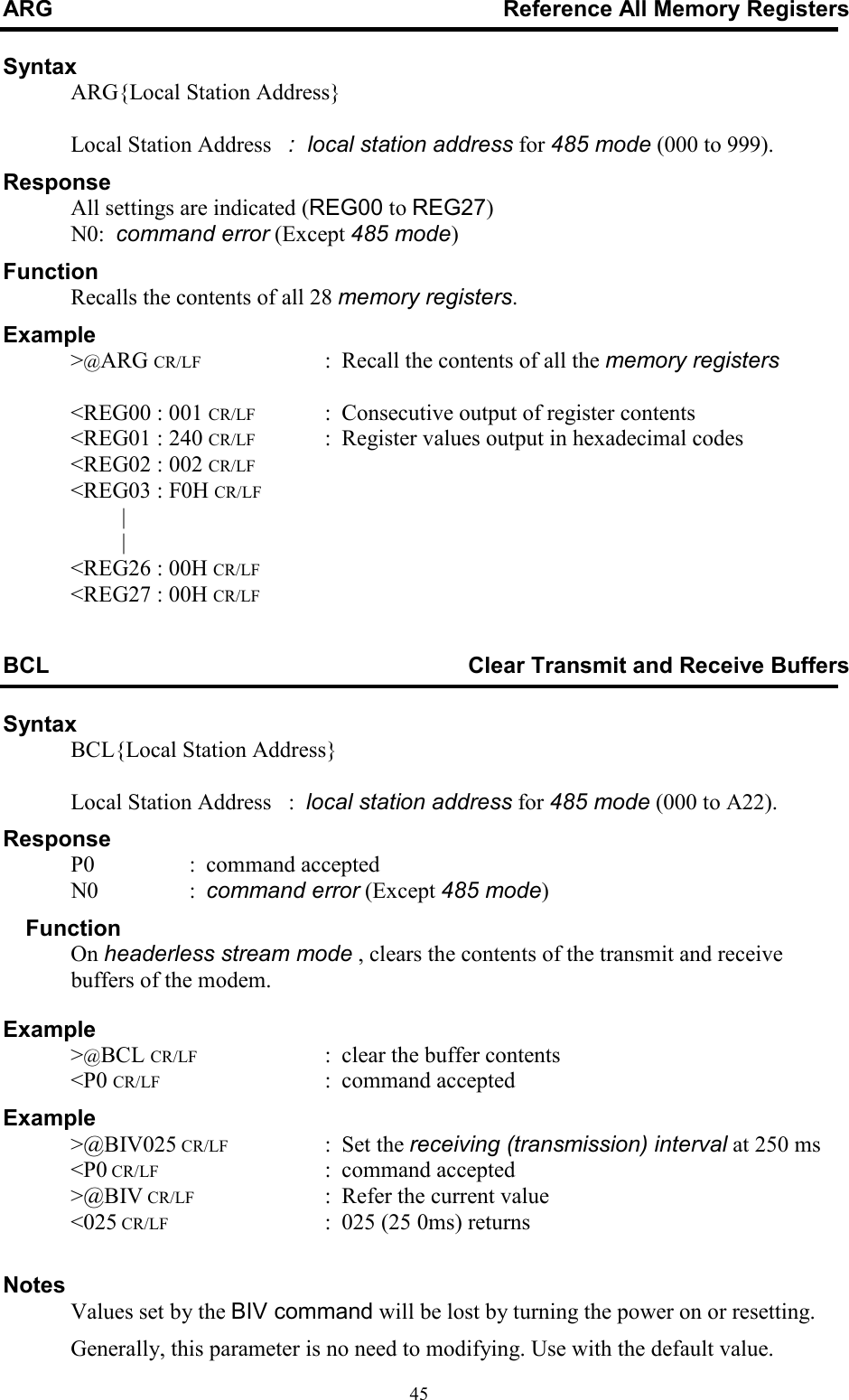
![446.1 Command Set Description This section provides a description of each command available in the FDL command set. The table below lists each command and it applicability in each operation mode. Command Function 1 ARG Reference All Memory Resisters 2 BCL Clear Transmit and Receive Buffers 3 CON Connect Wireless Link 4 DAS Reference and Set the Destination Address 5 DBM Read Signal Strength 6 DCN Disconnect Wireless Link 7 FRQ Reference and Set Frequency Group 8 INI Initialize All Memory Resisters 9 ODA Disable Received Data Output 10 OEN Enable Received Data Output 11 PAS Reference and Set Repeater Address 12 RDA Disable Wireless Reception 13 REG Reference and Set Memory Resisters 14 REN Enable Wireless Reception 15 RID Display Received Serial ID 16 RNO Reference and Set Retransmission Count 17 ROF RF Circuit Block Power Down 18 RON RF Circuit Block Power Up 19 RST Reset 20 SAS Reference and Set Local Station Address 21 STS Read Status 22 TBN Transmit Binary Data 23 TBR Transmit Binary Data Through Repeater 24 TID Display Local Station Serial ID 25 TXR Transmit Text Data Through Repeater 26 TXT Transmit Text Data 27 VER Reference Version Information Table 6–1: Command to Mode Availability The symbols used in this section have the following meaning: > : Input character from the terminal equipment to the modem < : Output from the modem to the terminal equipment @ : Command header CR/LF : Terminator (carriage return + line feed) [ ] : Required input parameter/s Be sure to input. ( ) : Optional input parameter/s May be omitted {} : 485 mode local station address (REG00). Be sure to input at 485 mode In the Syntax and Response segments of the following command descriptions the terminator symbol (CR/LF) has been omitted for clarity.](https://usermanual.wiki/Futaba/FDL01TU/User-Guide-595584-Page-58.png)
 {;Local Station Address} register number : register number to be set (00 to 27) value : value to be set. Input 2 hexadecimal digits (0 through 9 and A through F) followed by the number radix designator H. Local Station Address : local station address for 485 mode (000 to A22 ). Response xxx : current value (reference) P0 : command accepted (setting) N0 : command error (Except 485 mode) N6 : memory register write error Function References or sets memory registers. The current register value is referenced by omitting the “value” parameter. Example >@REG00 CR/LF : reference the contents of register 00 <01H CR/LF : displays current value >@REG00 : 023 CR/LF : set value of memory register 00 to 023 (decimal) <P0 CR/LF : command accepted Notes The register can be rewritten sequentially. However, to make its parameter valid after rewriting it, re-supply the power, reset the modem or use RST command.](https://usermanual.wiki/Futaba/FDL01TU/User-Guide-595584-Page-66.png)
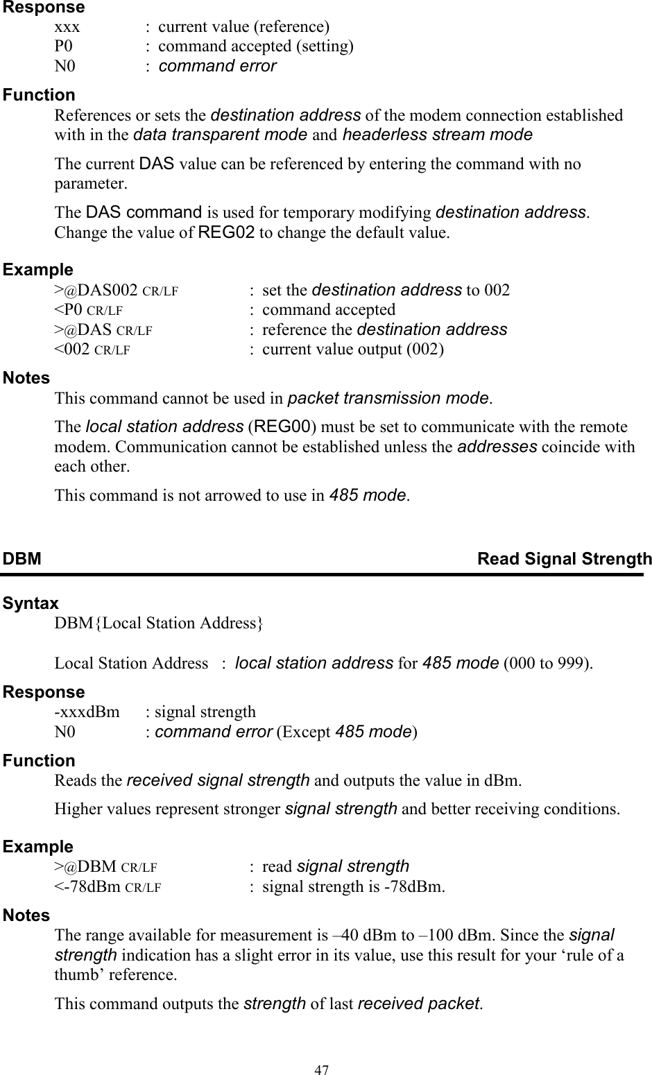
![57X X X X X X X X Status Bit Name 1 0 0 Connection Connected Disconnected 1 Reception Disabled Enabled 2 Output message Disabled Enabled 3 Receive buffer Data exist Data empty 4 Transmit buffer Data exist Data empty 5 Reserved - - 6 Reserved - - 7 Reserved - - Figure 6–2: Modem Status Bit Description Example >@STS CR/LF : read the current status <00001010 CR/LF : Received data exist, Output message enabled, Reseption disabled ,Disconnected. TBN Transmit Binary Data Syntax TBN[destination address][message byte length]{Local Station Address}[message] Destination address : address of the transmission (000 to A23) Message byte length : message length (001 to 255) Local Station Address : local station address for 485 mode (000 to A22). Message byte : arbitrary binary data (255 or less) Response P0 : data transmission succeeded P1 : command accepted, data being transmitted N0 : command error (Except 485 mode) N1 : data transmission failed -- no response from destination station N2 : data transmission failed -- destination station is in the reception disabled state N3 : data transmission failed -- destination station cannot receive because its receive buffer is full Function Transmits binary data in the packet transmission mode. Any message length between 1 to 255 bytes is accepted. The modem counts the number of message characters and transmits the message. For broadcasting messages to multiple modems, set the destination address to 255. In this case, the modem retransmits the message the number of times of the Retransmission count plus 1, and then it will return “P0”. In case the global addressing command is issued to plural modems connected by RS485 multi-dropping interface, the transmission stops when any modem outputs “P0”, “N2” or “N3” response to the RS485 line. Example >TBN002005HELLO CR/LF : transmit “HELLO” from station 001 to station 002 <P1 CR/LF : data being transmitted <P0 CR/LF : data transmission succeeded. >@TBN003004MAIL CR/LF : retransmit “MAIL” from station 001 to station 003](https://usermanual.wiki/Futaba/FDL01TU/User-Guide-595584-Page-71.png)
![58 <P1 CR/LF : data being transmitted <N1 CR/LF : transmission failed, no response from destination station Notes Set the message length to 255 byte or less. The message length exceeding 255 byte will be command error. Message must be terminated with 2 byte (CR/LF) character, others will be command error. In broadcast transmission, the receiving result of the destination station cannot be confirmed at the sender side. TBR Transmit Binary Data through Repeater Syntax TBR [repeater address] [destination address] [message byte length]{Local Station Address}[message] Repeater address : repeater address to pass through (000 to 999) Destination address : address of destination station (000 to A23) Message byte length : message byte length (001 to 255) Local Station Address : local station address for 485 mode (000 to A22). Message byte : arbitrary binary data (255 or less) Response P0 : data transmission succeeded P1 : command accepted, data being transmitted P2 : data packet reached to repeater N0 : command error (Except 485 mode) N1 : data transmission failed -- no response from destination station N2 : data transmission failed -- destination station is in the reception disabled state N3 : data transmission failed -- destination station cannot receive because its receive buffer is full Function In the packet transmission mode, transmits binary data through repeater. Any message length between 1 to 255 bytes is accepted. The modem counts the number of message characters and transmits the message. For broadcasting messages to multiple modems, set the destination address to 255. In this case, the modem retransmits the message the number of times of the Retransmission count plus 1, and then it will return “P0”. In case the global addressing command is issued to plural modems connected by RS485 multi-dropping interface, the transmission stops when any modem outputs “P0”, “N2” or “N3” response to the RS485 line. Example >TBR100002005HELLO CR/LF : transmit “HELLO” from station 001 to station 002 <P1 CR/LF : data being transmitted <P2 CR/LF : data packet reached to repeater <P0 CR/LF : data transmission succeeded Notes Set the message length to 255 byte or less. The message length exceeding 255 byte will be command error. Message must be terminated with 2 byte (CR/LF) character, others will be command error. In broadcast transmission, the receiving result of the destination station cannot be confirmed at the sender side.](https://usermanual.wiki/Futaba/FDL01TU/User-Guide-595584-Page-72.png)
![59TID Display Local Station Serial ID Syntax TID{Local Station Address} Local Station Address : local station address for 485 mode (000 to 999). Response XXXXXXXXXXXX : displays the local serial ID code (12 digits) N0 : command error (Except 485 mode) Function Readout the local serial ID code of the modem and display it. This command corresponds to RID command. The local serial ID code consists of 12 digits; upper three digits are 0 and the lower 9 digits are the product serial number of the modem. Be noted the usage of RID command, the serial ID code of the packet received last is displayed. When packets are received from multiple stations and their data are stored in the receiving buffer, those data may not correspond to the serial ID code readout with the RID command. To use it more securely, it is recommended to readout the local serial ID code with the TID command and pad it (either all or a part of it) in the transmitting packet. The serial ID code is no relation with ID code setting of REG04 and 05. Example >@TID CR/LF : requests the modem’s local serial ID code < XXXXXXXXXXXX CR/LF :outputs the modem’s local serial ID code TXR Transmit Text Data through Repeater Syntax TXR [repeater address] [destination address]{Local Station Address}[message] repeater address : address of repeater to pass through (000 to 999) destination address : address of destination station (000 to A23) Local Station Address : local station address for 485 mode (000 to A22). message : any text data (255 or less) Response P0 : data transmission succeeded P1 : command accepted, data being transmitted P2 : data packet reached to repeater N0 : command error (Except 485 mode) N1 : data transmission failed -- no response from the destination station N2 : data transmission failed -- destination station is in the reception disabled state N3 : data transmission failed -- destination station cannot receive because its receive buffer is full. Function Transmits text data in the packet transmission mode through repeater. Any message length between 1 to 255 bytes is accepted. The completion of data input is recognized by the terminator.](https://usermanual.wiki/Futaba/FDL01TU/User-Guide-595584-Page-73.png)
![60 For broadcasting messages to multiple modems, set the destination address to 255. In this case, the modem retransmits the message the number of times of the Retransmission count plus 1, and then it will return “P0”. In case the global addressing command is issued to plural modems connected by RS485 multi-dropping interface, the transmission stops when any modem outputs “P0”, “N2” or “N3” response to the RS485 line. Example >@TXR100002HELLO CR/LF : transmits HELLO from station 001 to station 002 through repeater 100 <P1 CR/LF : data being transmitted <P2 CR/LF : data packet reached to repeater <P0 CR/LF : data transmission succeeded Notes Set the message length to 255 byte or less. The message length exceeding 255 byte will be command error. When the same character as the terminator (CR/LF) is contained in a message, the modem distinguishes it as the end of a command and ignore the subsequent data. In such a case, use TBR command. In broadcast transmission, the receiving result of the destination station cannot be confirmed at the sender side. TXT Transmit Text Data Syntax TXT [destination address]{Local Station Address}[message] destination address : address of destination station (000 to A23) Local Station Address : local station address for 485 mode (000 to A22). message : any text data (255 or less) Response P0 : data transmission succeeded P1 : command accepted, data being transmitted N0 : command error (Except 485 mode) N1 : data transmission failed - no response from the destination station N2 : data transmission failed - destination station is in the reception disabled state N3 : data transmission failed – destination station cannot receive because its receive buffer is full. Function Transmits text data in the packet transmission mode. Any message length between 1 to 255 bytes is accepted. The completion of data input is recognized by the terminator (CR/LF). For broadcasting messages to multiple modems, set the destination address to 255. In this case, the modem will retransmit the message the number of times of the Retransmission count plus 1, and then it will return “P0”. In case the global addressing command is issued to plural modems connected by RS485 multi-dropping interface, the transmission stops when any modem outputs “P0”, “N2” or “N3” response to the RS485 line. Example >@TXT002HELLO CR/LF : transmits HELLO from station 001 to station 002 <P1 CR/LF : data being transmitted](https://usermanual.wiki/Futaba/FDL01TU/User-Guide-595584-Page-74.png)