Futaba FDL01TU Wireless Modem with Serial Interface User Manual
Futaba Corporation Wireless Modem with Serial Interface Users Manual
Futaba >
Users Manual

i
WIRELESS DATA COMMUNICATION MODEM
FDL01TU
Wireless Modem with Serial Interface
Instruction Manual
Futaba Corporation
Industrial Radio Control
ii
I
Notice
This device complies with part 15 of the FCC rules. Operation is subject to the following
two conditions: (1) This device may not cause harmful interference, and (2) this device
must accept any interference received, including interference that may cause undesired
operation.
This equipment has been tested and found to comply with the limits for a Class A digital
device, pursuant to part 15 of the FCC Rules. These limits are designed to provide
reasonable protection against harmful interference when the equipment is operated in a
commercial environment. This equipment generates, uses, and can radiate radio frequency
energy and, if not installed and used in accordance with the instruction manual, may cause
harmful interference to radio communications. Operation of this equipment in a residential
area is likely to cause harmful interference in which case the user will be required to correct
the interference at his own expense.
Any unauthorized changes or modifications to this device not expressly approved by Futaba
Corporation could void the user’s authority to operate the device and possibly result in
damage to the equipment and/or cause serious or fatal injuries to the operator or nearby
personnel.
This device is intended to be installed and used in accordance with the instructions
contained in this manual. Failure to comply with these instructions could void the user’s
authority to operate the device and possibly result in damage to the equipment and/or cause
serious or fatal injuries to the operator or nearby personnel.
iii
II
Important Safety Information
The list of dangers, warnings and cautions in this section contain important information that
will help ensure safe operation of the system. Please read carefully and understand all of
these items. All installers, operators and maintenance personnel should read and understand
this information before installation, use, or maintenance of the FDL01TU system.
The FDL01TU system by itself is not inherently dangerous. HOWEVER, WHEN THE
FDL01TU IS CONNECTED TO OTHER EQUIPMENT FOR THE PURPOSE OF
CONTROL, SAFETY AND ALL POSSIBLE ASSOCIATED DANGERS MUST
ALWAYS BE GIVEN THE UTMOST CONSIDERATION DURING SYSTEM
INTEGRATION, DESIGN, INSTALLATION, AND USE.
The FDL01TU system may be used in virtually unlimited applications. Many of these
associated systems can, by themselves, pose a mechanical, electrical or other hazard to
operators and other persons or equipment. To address all possible applications and
associated safety hazards in this manual would be impossible. The warnings below and
throughout this manual give information that will allow safe installation and use the modem
system applications. If you have questions regarding the safety of your specific application,
please contact the appropriate people for help. Your Futaba sales representative,
representatives of the equipment being controlled, and the technical support staff at local
branch of Futaba Corporation are among those who can provide assistance with your safety
concerns.
The following warnings are included in the lists that follow but warrant repetition
here:
In installations where the FDL01TU system is used to control motion or operation of
potentially dangerous equipment, it is imperative for safety that all operators and installers
be thoroughly trained in the normal function of that equipment before attempting to control
it remotely with the FDL01TU system.
To help ensure safe operation of the equipment, the FDL01TU system must be connected
so that it will operate in a fail-safe way. In other words, the equipment being controlled
should stop or return to its safest state in the absence of a control signal or total loss of RF
transmission from the FDL01TU system. Our system uses one of the most reliable methods
available to transmit data using radio signals. Many factors can affect a radio signal that
may block it or interfere enough to disrupt regular transmission. Because of this, equipment
motion or dangerous electrical current, for example, that continues during a loss-of-signal
condition could be very dangerous.
iv
Four symbols are used in the margin of the following section and throughout the manual to
indicate the level of hazard or information listed.
The symbols are defined as follows:
Indicates a hazard that will cause severe personal injury, death, or
substantial property damage if the warning is ignored.
Indicates a hazard that can cause severe personal injury, death, or
substantial property damage if the warning is ignored.
Indicates a hazard that will or can cause minor personal injury, or
property damage if the warning is ignored.
Indicates installation, operation, or maintenance information that is
important but not hazard-related.
Please read the following safety information carefully. Some of these notices are duplicated
throughout the manual, in areas of associated content, for your benefit.
II.I
General Safety Hazards and Notes
Improper installation and/or operation of the FDL01TU system can
cause serious or fatal injuries to the operator or nearby persons and
cause damage to the FDL01TU system, and any equipment it is used
to control. Please read and understand this manual completely and
the manual of all equipment being controlled before attempting to
operate or install this system.
Always keep this manual at a location readily accessible to anyone
operating the system and related equipment. Ensure that all operators
have read and understood this manual, especially all safety and
operation procedures contained in it. Please refer to the section in
this manual titled How to Obtain Help for the contact that can
supply additional manuals or answers to questions not covered in this
manual. If this product is passed on to a different user, be sure that
this manual accompanies the product.
Be certain that the installer of this equipment reads and understands
the instruction manual of the equipment that is being connecting to
before attempting this installation.
The FDL01TU modem should NOT be used in a manner in which
failure of the product or loss of the radio signal could cause damage

v
to the equipment being controlled, or to anything in the area in which
such equipment is located. All integrated control systems should be
designed for “fail-safe” operation so that a temporary or permanent
loss of signal will not endanger any person, critical process, or
equipment (refer to the beginning of the safety section for further
explanation). The system design should ensure that the equipment
being controlled will default to its safest state in the event of signal
loss.
The FDL01TU modem contains no user serviceable parts. If the unit
requires service, contact your sales representative or local branch of
Futaba Corporation per instructions the section titled How To
Obtain Help. Do not disassemble or attempt to repair the FDL01TU
yourself. Doing so could void your warranty and may void the user’s
authority to operate the device.
Contact Futaba before using the FDL01TU modem in safety critical
applications such as medical equipment, aircraft, hazardous materials
handling, etc.
II.II
Installation Safety Hazards and Notes
When mounting the FDL01TU modem, use M2 (ISO) screws that
project 2 to 3 mm into the modem. Screws that project further into
the modem (3.5mm MAX) may permanently damage the internal
components and/or cause the FDL01TU modem to malfunction.
Use only the proper regulated DC voltage supplied to the FDL01TU
modem. Use of any other voltage may permanently damage the
modem and/or cause the modem to malfunction and create a shock or
fire hazard.
Be certain that all AC power outlets used the power adapters have
been properly installed, grounded, and fused. An electrical shock
hazard may exist if this unit is powered by a faulty power outlet or
source. If such a situation is discovered, immediately discontinue use
until the power source and outlet have been properly installed,
grounded, and fused by an electrician or other authorized person.
Be sure to wire the power and serial connections correctly. Incorrect
wiring can damage the system, cause it to malfunction and/or create
a shock and fire hazard.
Ensure that the FDL01TU modem power and the power to the
equipment to be controlled is turned off before connecting or
disconnecting the cable between them. This will help prevent

vi
accidental damage to the system and unexpected operation and/or
injury.
Be sure the FDL01TU modem power, the power to the equipment
that is being connecting to it, and the DC power source are all turned
off before wiring and connecting the power cable.
Be sure that the supplied power is within the specified range (3.5 to
7.0 VDC). Voltages outside the specified range may damage the
FDL01TU modem.
Be sure that the power source has sufficient current capacity.
Insufficient current may cause the unit to malfunction.
Securely attach the antenna cable, and serial communication
connector to the FDL01TU modem and equipment/power source to
which it is connected. Failure to do so could cause an unexpected
system failure.
II.III
Antenna Installation Hazards and Notes
Be sure to keep all systems and antennas clear of power lines.
Permanent equipment damage and severe shock injury or death can
occur if the system contacts power lines.
This device has been designed to operate with an antenna having a
maximum gain of 2.14 dB. Antenna having a higher gain is strictly
prohibited for use with this device. The required antenna impedance
is 50 ohms.
Contact Futaba before connecting any antenna not provided by
Futaba specifically for the FDL01TU modem. Attaching any non-
authorized antenna may be in violation of FCC regulations.
To reduce potential radio interference to other users, the antenna type
and its gain should be so chosen that the equivalent isotropically
radiated power (e.i.r.p.) is not more than that permitted for successful
communication.
When using two antennas with a single FDL01TU modem for
diversity reception, mount the antennas as far apart as possible (6 cm
minimum). If the antennas are too close, the diversity advantage will
not be achieved.
vii
Before each use, verify that the antenna (and antenna cable, if used)
is securely attached and in good condition. A loose antenna or cable
may severely reduce the operating range of the system.
When installing the FDL01TU modem in a mobile unit such as an
Automated Guided Vehicle (AGV), Futaba recommends to use the
diversity reception feature as a remedy for multipath fading problems.
For diversity reception, install the two antennas as far apart as
possible in order to gain maximum benefit (6 cm minimum).
The FDL01TU operates at frequencies in the 2.4 GHz band. These
frequencies are more directional than lower frequencies and are
easily reflected. If there are metal structures nearby, the effective
range may be shortened or the directional properties may be further
narrowed. To help avoid this, mount the antenna as far away as
possible from surrounding metallic structures.
Multipath problems occur easily at frequencies in the 2.4 GHz band.
When multipath problems are present, moving the antenna as little as
10 cm may result in improved communication or, conversely,
worsened or complete loss of communication. Futaba recommends
that the mounting position of the antenna be determined after testing
and verifying optimal communication conditions. Negative multipath
effects can also be overcome with antenna diversity. See p.8
D
IVERSITY
A
NTENNA
S
ETUP
and the related register settings for
more details regarding antenna diversity function.
When installing multiple FDL01TU modem systems that will use
different frequency groups in the same area, modem’s antennas of
different frequency groups must be mounted at least 6 feet (2 meters)
apart. Failure to do so may severely reduce the modem operating
range.
Please contact Futaba for information about antenna separation when
using the FDL01TU and other wireless products in the same area.

viii
II.IV
Environmental Safety Hazards and Notes
If the FDL01TU modem has been stored at a temperature beyond the
specified operating temperature range for the system, it may not
function properly. Allow it to return to normal temperatures before
use. Refer to A
PPENDIX
A – T
ECHNICAL
S
PECIFICATIONS
for the
actual operating temperature range.
The FDL01TU modem is a precision electronic device with a rugged
design that is intended for industrial applications. However, do not
install it where it will encounter excessive vibrations. In some cases,
isolation mounts may be used to isolate the modem from the
equipment’s vibration. Excessive vibration can permanently damage
the modem and/or cause it to malfunction.
Do not operate the FDL01TU modem in environments where it will
be subjected to excessive moisture (such as rain or water spray), dust,
oil, or other foreign matter (such as metal particles). Doing so may
permanently damage the modem and/or cause it to malfunction. If it
does become wet or contaminated, correct the situation, verify proper
operation and have any problems corrected before using it to control
other equipment. If necessary, the modem can be mounted inside a
protective or waterproof enclosure. If the enclosure is metallic, the
antenna must be mounted externally or the effective operating range
will be severely limited.
The FDL01TU is designed for indoor use. When using it outdoors,
the modem should be mounted in a waterproof enclosure and the
ambient temperature range should be checked to insure that it is
within the modem’s specifications. Always use the modem within its
specified environmental ranges.
II.V
Other Notice
Italicized gothic word used in this manual shows functional and
technical term especially important for the FDL01TU modem.

ix
Operational Safety Hazards and Notes
Before each use of the FDL01TU modem, ensure that the area where
the equipment will be operated is clear of people or obstacles that
may affect its safe operation.
Before each use of the FDL01TU modem, verify that both the
equipment being controlled and the modem are in proper operating
condition.
When rewriting the FDL01TU modem’s memory registers, do not
turn the modem’s power off until the modem returns a “P0” response.
If the power is interrupted before a P0 response is returned, the
memory contents may be lost or corrupted and the modem operation
will be unpredictable. If the memory contents are lost or corrupted,
they may be restored to original default settings by reinitializing
them. (See p.25 Memory R
EGISTER
I
NITIALIZATION
for more
details.)
Do not attempt to operate remotely controlled equipment outside the
communication range of the FDL01TU system. Doing so could cause
loss of control of the equipment.
Without implementing proper serial communication flow control
settings, the baud rate between the modem and its terminal
equipment (wire linked) can exceed the wireless link data rate and
cause the modem buffer to overflow. This can result in malfunction
of the systems being controlled and/or data corruption. Ensure that
the appropriate flow control settings are being used for your upper
layer application protocol.
Operation is subject to the following two conditions: (1) this device
may not cause interference, and (2) this device must accept any
interference, including interference that may cause undesired
operation of the device.

x
III
System Identification
For future reference, please take a moment to fill in the information below. This
information will help us respond as quickly as possible should your FDL01TU modem ever
need repair or replacement.
Model Name and Number: FDL01TU
Serial Number:
Date of Purchase:
Distributor Name:
Distributor Address:
Distributor Phone Number:
xi
IV
Limited Warranty
FUTABA WARRANTS ONLY THAT THE INDUSTRIAL RADIO CONTROL SYSTEM
GOODS OR PRODUCTS FURNISHED HEREWITH SHALL BE FREE FROM
DEFECTS IN MATERIAL AND WORKMANSHIP UNDER NORMAL CONDITIONS
OF USE AND SERVICE FOR A PERIOD OF ONE (1) YEAR FROM THE DATE OF
SALE TO THE PURCHASER WHO IS THE FIRST BUYER OF THE GOODS FOR USE
OR CONSUMPTION AND NOT FOR RESALE OTHER THAN AS A COMPONENT
OF ANOTHER PRODUCT MANUFACTURED FOR SALE BY SUCH PURCHASER
(“CONSUMER”). FUTABA’S LIABILITY, WHETHER BASED ON BREACH OF
WARRANTY OR NEGLIGENCE, SHALL BE LIMITED, AT FUTABA’S ELECTION,
TO REPLACEMENT OR REPAIR OF ANY SUCH NONCONFORMING GOODS,
F.O.B. FUTABA’S U.S.A. PLANT, OR, AT FUTABA’S ELECTION, CREDIT FOR THE
NET PURCHASE PRICE OF SUCH GOODS. ALL CLAIMS HEREUNDER MUST BE
MADE IN WRITING DURING THE WARRANTY PERIOD, AND FUTABA SHALL
HAVE THE RIGHT PRIOR TO ANY RETURN OF GOODS TO INSPECT ANY
GOODS CLAIMED TO BE NONCONFORMING, AND IN ANY EVENT RESERVES
THE RIGHT TO REJECT CLAIMS NOT COVERED BY WARRANTY. THIS LIMITED
WARRANTY CONSTITUTES FUTABA’S SOLE WARRANTY. FUTABA MAKES
NO OTHER WARRANTY OF ANY KIND, EXPRESS OR IMPLIED, AND
EXPRESSLY DISCLAIMS ANY IMPLIED WARRANTY OF
MERCHANTABILITY OR FITNESS FOR A PARTICULAR PURPOSE.
FUTABA’S WARRANTY SHALL NOT APPLY IF, AMONG OTHER LIMITATIONS
CONTAINED HEREIN OR FURNISHED WITH THE PRODUCT, BUYER, OR
CONSUMER, OR ANY USER OF THE PRODUCT (A) ALTERS SUCH PRODUCT,
OR (B) REPLACES ANY PART OF SUCH PRODUCT WITH ANY PART OR PARTS
NOT FURNISHED BY FUTABA FOR THAT PURPOSE, OR IF, AMONG SUCH
OTHER LIMITATIONS, PRODUCT FAILS TO OPERATE PROPERLY OR IS
DAMAGED DUE TO ATTACHMENTS OR COMPONENTS THAT ARE NOT
FURNISHED BY FUTABA FOR USE WITH OR REPAIR OF THE PRODUCT UNLESS
SUCH USE IS AUTHORIZED IN WRITING IN ADVANCE BY FUTABA.
THIS LIMITED WARRANTY EXTENDS ONLY TO THE CONSUMER AND IS NOT
ASSIGNABLE OR TRANSFERABLE. This limited warranty shall not apply to fuses,
lamps, batteries, or other items that are expendable by nature, unless otherwise expressly
provided.
This limited warranty does not cover any defect or damage to any of the goods caused by or
attributable to force, accident, misuse, abuse, faulty installation, improper maintenance,
improper electrical current, failure to install or operate in accordance with Futaba’s written
instructions, repair or alteration by unauthorized persons, or leaking batteries. THE
GOODS ARE SENSITIVE ELECTRONIC DEVICES REQUIRING SPECIAL
HANDLING, AND THIS LIMITED WARRANTY DOES NOT APPLY TO
PRODUCTS NOT HANDLED IN ACCORDANCE WITH INSTRUCTIONS SET
FORTH IN THE MANUAL.
THIS LIMITED WARRANTY DOES NOT COVER INDUSTRIAL RADIO
CONTROL PRODUCTS PURCHASED OR USED OUTSIDE OF THE UNITED
STATES WITHOUT FUTABA’S PRIOR APPROVAL.
xii
V
Returns
Futaba’s authorization must be obtained prior to return of any item for warranty or other
repair or replacement or credit and will reflect Futaba’s warranty service procedure.
Consumer’s warranty rights are governed by the terms of Futaba’s Limited Warranty, as
above described. Products returned for warranty repair or replacement or credit must be
carefully and securely packed for return, preferably in the original carton or equivalent. The
Consumer must also include in the carton a legible copy of the bill of sale or invoice which
shows the date of sale and the original Buyer’s and Consumer’s names, and also a letter
which gives the Consumer’s return address and contact telephone number, the model and
serial numbers of the product(s) returned, and a brief explanation of the problem or claimed
defect. Any returned products that are replaced by Futaba shall become the property of
Futaba. If after inspection Futaba determines the defect is not covered by its limited
warranty, Futaba will notify Consumer of its determination and will not undertake any
repairs or product replacement until Consumer agrees to pay for all necessary parts and
materials, labor (to be charged at Futaba’s standard repair rate then in effect), and other
expenses including all shipping charges and insurance. Futaba reserves the right to retain
possession of any product returned by Consumer because of defects not covered by
Futaba’s warranty until Futaba receives Consumer’s agreement as above noted or, if
Consumer wants the product returned without repair or replacement, Consumer reimburses
Futaba for all shipping and handling charges incurred by Futaba. Issuance of credit for
returned items shall be made at Futaba’s unfettered discretion. Consumer will not be
entitled to return defective goods for cash refunds. Consumer must inspect goods
immediately and no rejection or revocation of acceptance shall be permitted more than ten
(10) days after delivery to, or first use by, Consumer of the goods, whichever occurs first.
VI
Patents – Copyrights – Trademarks – Proprietary
Rights
If this product was manufactured according to designs or processes specified by Consumer,
Consumer shall indemnify and save Futaba, its affiliates, officers, agents, and employees,
harmless from any expense, loss, attorneys’ fees, costs, damages, or liability which may be
incurred as a result of actual or alleged infringement of patent, copyright, or trademark
rights. Furnishing of these products does not convey a license, implied or otherwise, under
any patent, copyright, or trademark right in which Futaba has an interest, nor does it convey
rights to trade secrets or any other proprietary information of Futaba.
VII
Limitation of Damages and Action
IN NO EVENT SHALL FUTABA BE LIABLE TO CONSUMER, OR ANY OTHER
PERSON FOR ANY INCIDENTAL, CONSEQUENTIAL, OR SPECIAL DAMAGES
RESULTING FROM THE USE OF OR INABILITY TO USE THIS PRODUCT,
WHETHER ARISING FROM BREACH OF WARRANTY OR NEGLIGENCE OF
FUTABA, OR OTHERWISE. Any action hereunder must be commenced within one (1)
year of accrual of cause of action or be barred and forever waived. No modification or
alteration of Futaba’s Limited Warranty or any other provision of this paragraph or the
above paragraphs shall result from Futaba’s acknowledgment of any purchase order,
shipment of goods, or other affirmative action by Futaba toward performance following
receipt of any purchase order, shipping order, or other form containing provisions, terms, or
conditions in addition to or in conflict or inconsistent with any such provisions.
xiii
TABLE OF CONTENTS
1
11
1
INTRODUCTION............................................................................................... 1
1.1
Special Features.............................................................................................................2
1.2
How To Obtain Help........................................................................................................3
1.3
Physical Description .......................................................................................................4
2
22
2
SYSTEM INSTALLATION ................................................................................ 5
2.1
Wireless Modem Installation...........................................................................................6
2.2
Communication Cable Connection.................................................................................7
2.3
Antenna Connection .......................................................................................................7
2.4
Other Installation Precautions ........................................................................................9
3
33
3
SYSTEM OPERATION ................................................................................... 11
3.1
Data Transparent Mode................................................................................................12
3.2
Packet Transmission Mode ..........................................................................................13
3.3
Headerless stream Mode .............................................................................................16
3.4
Power Down Mode .......................................................................................................17
3.5
Frequency Grouping.....................................................................................................18
4
44
4
FUNCTION CONTROL METHODS ................................................................ 21
4.1
Interface........................................................................................................................22
4.2
Serial Interface Setting .................................................................................................23
4.3
Terminal Software Setup for Memory Register Control................................................24
4.4
Memory Register Setting..............................................................................................24
4.5
Command Control ........................................................................................................26
5
55
5
MEMORY REGISTER DESCRIPTION ........................................................... 27
5.1
Memory Register Description .......................................................................................28
6
66
6
COMMAND SET DESCRIPTION.................................................................... 43
6.1
Command Set Description............................................................................................44
7
77
7
APPENDIX...................................................................................................... 63
7.1
Conversion Circuit ........................................................................................................64
7.2
Specification of the Connectors....................................................................................65
7.3
Specification..................................................................................................................66
7.4
Dimensions ...................................................................................................................68

1
1
SECTION
1 INTRODUCTION

2
1.1
Special Features
The following list highlights some of the special features of the FDL01TU. For more
complete system specifications please refer to p.66 S
PECIFICATIONS
.
•
Approved under FCC Part 15.247 rules -- no special user license required
•
Operating range greater than 1000 feet, line-of-sight -- configurable as a repeater for
extended range of application service area
•
2.4 GHz Direct Sequence Spread Spectrum (DSSS) communication system provides
unsurpassed immunity to interference and RF noise
•
Diversity transmitting / receiving function is employed, which is practically
invulnerable to multipath fading
•
Fast switching Time-Division-Duplex (TDD) provides virtual full-duplex
communication between terminal equipments at rates up to 230.4 kbps
•
76 user selectable frequencies allow up to 26 independent networks to operate
simultaneously in the same area
•
Single fixed frequency communication or multi-access communication (automatic
selection of an vacant frequency from a defined group of frequencies) allows the user
to select the best frequency use for the application
•
Supports 1:1, 1:n, and n:m wireless network topology
•
Serial communication interface allows direct connection to a micro controller chip. By
converting its level by the external interface circuit, conformable to RS232C, RS422
and RS485
•
Small size allows easy integration with many systems (1.97" x 1.18" x 0.31" / 50 x 30
x 8 mm)
•
Supply voltage range is DC voltage in 3.5 to 7.0 V DC

3
1.2
How To Obtain Help
Please contact your local sales representative or local branch of Futaba Corporation at the
address shown below for help with the following:
•
Application information regarding the FDL01TU or other Futaba products
•
Technical assistance or training
•
Answers to safety questions and issues
•
Additional manuals or other documentation
•
Repair or service
•
Comments regarding the product or this manual
Japan
Futaba Corporation
Radio Control Equipment Group
1080 Yabutsuka, Chosei,
Chiba, 299-4395 JAPAN
Tel: +81 (475) 32-6173, Fax: +81(475) 32-6179
Internet: www.futaba.co.jp
Europe
PENDING
When requesting repairs, please provide as much detail as possible regarding the failure and
its cause or symptoms. Doing so will help our service department find the problem quickly,
resulting in a shorter repair time.
The FDL01TU modem contains no user serviceable parts. If the unit
requires service, contact your sales representative or local branch of
Futaba Corporation as per instructed in this section. Do not
disassemble or attempt to repair the modem yourself. Doing so could
void your warranty and may void the user’s authority to operate the
device.
CAUTION
4
1.3
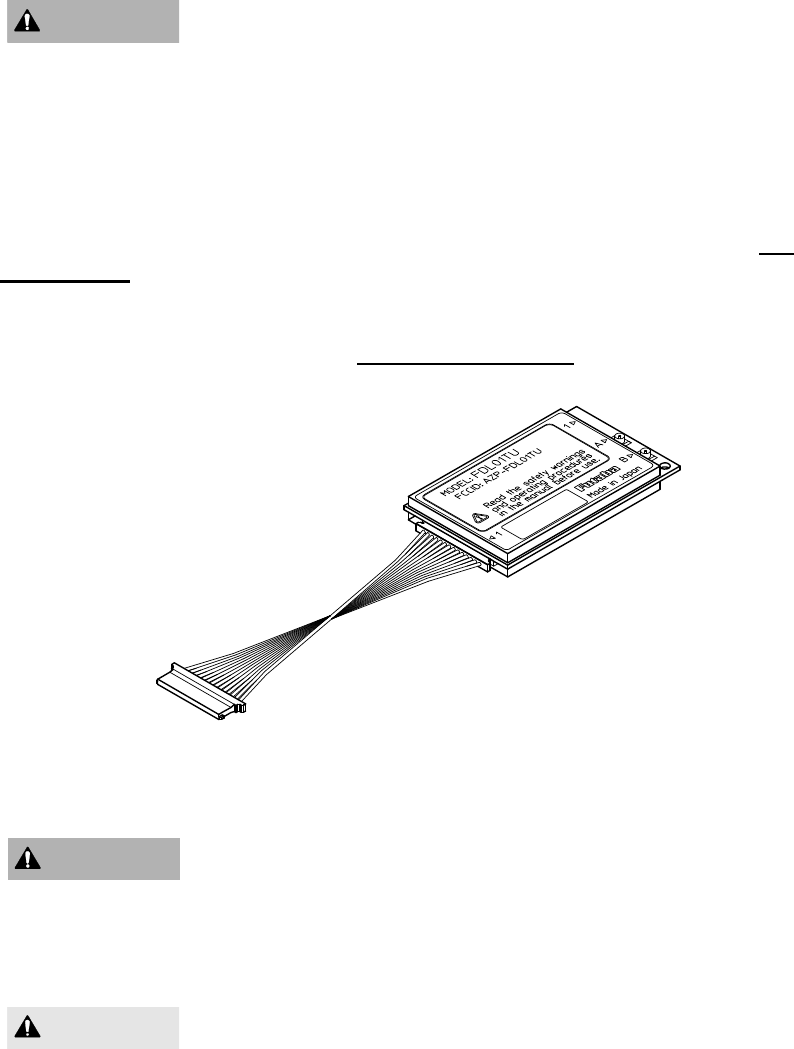
Physical Description
Please review the following section and take a moment to familiarize yourself with the
FDL01TU wireless modem.
Figure 1–1: Upper View
Figure 1–2: Bottom View
(1) Communication Connector
Used to connect to the DTE(Data Terminal Equipment) with interface cable. Also
controlling functions such as hardware reset and RS232C/RS485 selecting pins are
available. Signal is CMOS level.
(2) Antenna Connector A/B
Used to connect to antennas for transmit and receive functions.
(3) LEDs
Four bi-color LEDs indicate the states of the FDL01TU modem.
(4) Mounting Hole
Used to install a modem from the front surface. It is easy to install a modem, however, only
two holes are available, it should be fixed by guide structure on the other side of the unit to
prevent vibration problem.
(5) Bottom Mounting Hole
The four holes are used to install the modem. Please use this holes instead of above
explained holes if tightened mounting is required.

5
2
SECTION
2 SYSTEM INSTALLATION
6
2.1
Wireless Modem Installation
2.1.1 Mounting Method 1
A method to mount the modem directly on a surface using the mounting holes at the side of
the modem’s print circuit board. When using this method, provide a guide on the opposite
side, because two holes are not sufficient to securely mount the modem.
Figure 2–1: Mounting Method 1
2.1.2 Mounting Method 2
To mount the modem using the holes on a flat horizontal surface, which are 3.5mm deep
for M2 screws. When using this method, use M2 screws which project the hole 2 to 3mm
deep. The screw tightening torque is below 2.5kg cm. Mount the modem on a flat plane
and be careful that there is no torsion applied. For the position of the mounting holes, see
p.68 D
IMENSIONS
.
Figure 2–2: Mounting Method 2
Be careful not to allow water, oil, dust and other foreign particles
(especially metal particles) to enter inside, which may damage the
unit.
Since the FDL01TU modem is a precision electronic device, install it
at a place free of excessive shock and vibration to prevent the unit
from damage.
WARNING
M2 Screw
WARNING
7
The FDL01TU is designed to be used inside the room. In case of
using it outdoor, be sure to use it within the extent limited by the
environmental specification, and check the ambient temperature and
the state of water-proof.
2.2
Communication Cable Connection
Use the serial communication cable prepared by Futaba to connect the FDL01TU modem
to the external terminal equipment. For the connection of the modem, see p.22 P
IN
A
SSIGNMENT
.
The signal level of the FDL01TU is CMOS. If the interface of the equipment to be
connected is RS232C or RS485, the level conversion circuit is required. For the example of
the level conversion circuit, see p.64 C
ONVERSION
C
IRCUIT
.
Figure 2–3: Connection of Communication Cable
Ensure that the FDL01TU modem power and the power to the
equipment to be controlled is turned off before connecting or
disconnecting the cable between them. This will help prevent
accidental damage to the system and unexpected operation and/or
injury.
In addition to this manual, read the operation manual of a PC
(Personal Computer) and PLC (Programmable Logic Controller) to
be connected.
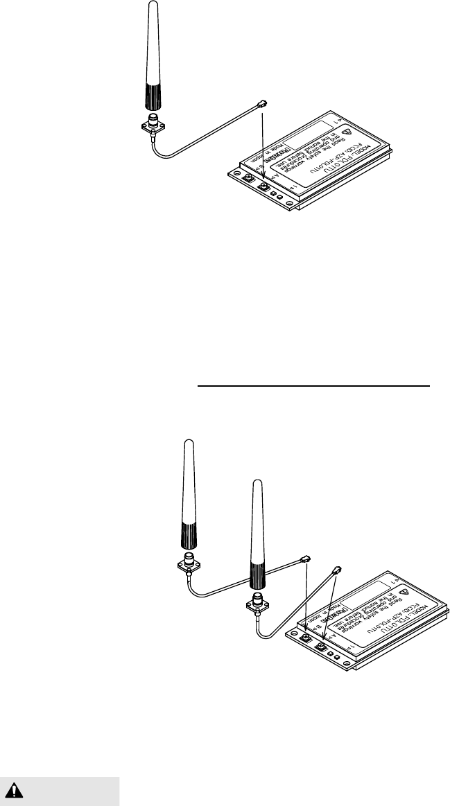
2.3
Antenna Connection
At least one antenna must be connected to Antenna Connector A on each FDL01TU
modem in use. In the environment where multipath fading exists with reliable
communication requirements, a second antenna can be installed to Antenna Connector B
for the diversity receive function to improve reception performance.
2.3.1 Single Antenna Setup
Always use Antenna Connector A when installing a single antenna.
Refer to the figures below for details about the actual mounting and connecting methods.
CAUTION
WARNING
WARNING
8
Figure 2–5: Connecting the Antenna
2.3.2 Diversity Antenna Setup
In certain situations, reception can be improved by using the integrated antenna diversity
feature. This is accomplished by using two separate antennas and enabling the diversity
function in REG19 (see p.27 M
EMORY
R
EGISTER
D
ESCRIPTION
).
Refer to the figures below for details about the actual mounting and connecting methods.
Figure 2–6: Connecting Two Antennas
When using two antennas with a single modem for diversity
reception, mount the antennas as far apart as possible (at least 6 cm).
If the antennas are too close, the diversity advantage will not be
achieved.
CAUTION

9
2.4
Other Installation Precautions
2.4.1 Modem Installation Precautions
Securely attach the antenna cable, and serial communication
connector to the FDL01TU modem and equipment/power source to
which it is connected. Failure to not do so could cause an unexpected
system failure.
The FDL01TU modem is a precision electronic device. Its rugged
design is intended for industrial applications. However, do not install
it where it will encounter excessive vibrations. In some cases,
isolation mounts may be used to isolate the modem from the
equipment vibration. Excessive vibration could permanently damage
the modem and/or cause it to malfunction.
If the FDL01TU modem has been stored at a temperature beyond the
specified operating temperature range for the system, it may not
function properly. Allow it to return to normal temperatures before
use. Refer to p.66 S
PECIFICATION
for the actual operating
temperature range.
Do not operate the FDL01TU modem in environments where it will
be subjected to excessive moisture (such as rain or water spray), dust,
oil or other foreign matter (such as metal particles). Doing so may
permanently damage the modem and/or cause it to malfunction. If it
does become wet or contaminated, correct the situation, verify proper
operation and have any problems corrected before using it to control
other equipment. If necessary, the modem can be mounted inside a
protective or waterproof enclosure. If the enclosure is metallic, the
antenna must be mounted externally or the effective operating range
will be severely limited.
The FDL01TU is designed for indoor use. When using it outdoors,
the modem should be mounted in a waterproof enclosure and the
ambient temperature range should be checked to insure that it is
within the modem’s specifications. Always use the modem within its
specified environmental ranges.
2.4.2 Antenna Installation Precautions
Before each use, verify that the antenna (and antenna cable, if used)
is securely attached and in good condition. A loose antenna or cable
may severely reduce the operating range of the system.
WARNING
WARNING
WARNING
WARNING
WARNING
WARNING
10
Avoid mounting the antenna near large metallic objects or inside
metal enclosures. Such objects can severely reduce the operating
range of the system.
When installing the FDL01TU modem in a mobile unit such as an
Automated Guided Vehicle (AGV), Futaba recommends using the
diversity receive function as a remedy for to multipath fading
problems. For diversity reception, install the two antennas as far
apart as possible in order to gain maximum benefit (Actual
recommendation is 30 cm, 6 cm at least).
The FDL01TU operates at frequencies in the 2.4 GHz band. These
frequencies are much directional than lower frequencies and are
easily reflected. If there are metal structures nearby, the effective
range may be shortened or the directional properties may be further
narrowed. To help avoid this, mount the antenna as far away as
possible from surrounding metallic structures.
Multipath problems occur easily at 2.4 GHz frequencies. When
multipath problems are present, moving the antenna as little as 10 cm
may result in improved communication or, conversely, a further
diminished or total loss of communication. Futaba recommends that
the mounting position of the antenna be determined after testing and
verifying optimal communication conditions. Negative multipath
effects can also be overcome with antenna diversity. See p.8
D
IVERSITY
A
NTENNA
S
ETUP
and the related register settings for
more details regarding antenna diversity.
2.4.3 Multiple FDL Modems Installation Precautions
When installing multiple FDL (series) modem systems that will use
different frequency groups in the same area, modem’s antennas of
different frequency groups must be mounted at least 6 feet (2
meters) apart. Failure to do so may severely reduce the modem
operating range.
Please contact Futaba for information about antenna separation when
using the FDL01TU and other wireless products in the same area.
WARNING
CAUTION
CAUTION
CAUTION

11
3
SECTION
3 SYSTEM OPERATION
12
3.1
Data Transparent Mode
3.1.1 What Is Data Transparent Mode?
In data transparent mode, the FDL01TU modems are continuously connected in a 1:1
configuration. Full-duplex communication is simulated between the two terminals using a
method in which each modem rapidly switches between transmitting and receiving
(referred to as Time-Division-Duplex (TDD) transmission).
With the exception of FDL01TU modem commands, all data input from the sending
terminal are transmitted to the receiving terminal. Using this mode, the user can simply
replace a serial cable with a pair of FDL01TU modems and communicate without any
special software or hardware requirements.
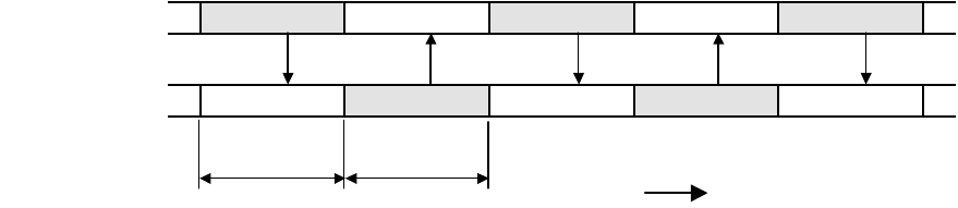
3.1.2 Time-Division-Duplex Transmission and ARQ Function
As noted above, when in data transparent mode, data packets are exchanged between
terminals the modems rapidly switching between transmitting and receiving, simulating
full-duplex communication.
Data input to the sending FDL01TU modem are assembled together with error detection
bits and other control data, and then transmitted to the receiving modem. If an error is
detected by the receiving modem, it will continue to request retransmission of the packet
from the transmitting modem until it receives a valid packet. This is referred to as the
Automatic Retransmission Request (ARQ) function. The ARQ function greatly enhances
the reliability of the wireless connection because it ensures that the receiving FDL01TU
modem will not pass corrupted data on to its terminal.
Figure 3–1: Send/Receive Timing Diagram
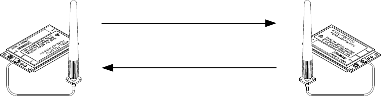
3.1.3 Connection Method
Link is connected and disconnected with the CON and DCN commands. Receiving
modems can be shifted among many others by designating station addresses.
Wireless Modem A send receive send receive send
Wireless Modem B receive send receive send receive
packet length A packet length B
time (t)
13
3.2
Packet Transmission Mode
Packet transmission mode operates as half-duplex communication and requires explicit
commands to control the modem transmissions. Because this mode allows the addressing of
different destination receiver modems by embedding the address in the data packets, it is
best suited for 1:n and n:m topology applications.
In packet transmission mode, the FDL01TU modem normally waits in a ready-to-
receive state.
When a transmission command is issued to the sender modem from its terminal equipment,
the modem searches for a clear frequency channel and, when found, transmits the message
to the intended destination receiver modem.
Packet transmission mode also allows expansion of the effective wireless
communication range by using an additional FDL01TU modem configured as a repeater.
3.2.1 Packet Transmission Mode Protocol
In packet transmission mode, after a data packet is transmitted from the sender modem
(station) to a destination station, the destination station acknowledges successful
communication by returning an acknowledgement (ACK) packet to the sender modem.
The sender modem waits for the ACK packet and when it is received, indicates that the
transmission was successful. If it does not receive an ACK packet, it will continue to
retransmit the data packet until it does receive an ACK packet or until the retransmission
count (REG11 or RNO command setting) reaches the preset limit. If the sender modem
receives an ACK packet anytime during the retransmission attempts, it returns a
“successive completion response” (P0) code to its terminal equipment. If the modem
does not receive an ACK packet, it returns a “transmission failed” (N1) code to its
terminal equipment.
Sender Modem Destination Modem
Figure 3–2: Packet Transmission and ACK response
3.2.2 Broadcast Transmission Protocol
Broadcast transmission (sending the same data to multiple modems simultaneously) is
possible in packet transmission mode by setting 255 as the destination address
(REG02). However, because ACK packet are not returned when executing the broadcast
transmission, the sender modem does not receive confirmation of the “successful
reception” of the transmitted data from any of the receiver modems.
In broadcast transmission, the sender modem transmit the data packet the number of
times equal to the preset retransmission count (REG11 or RNO command setting) plus
Data Transmission
ACK response
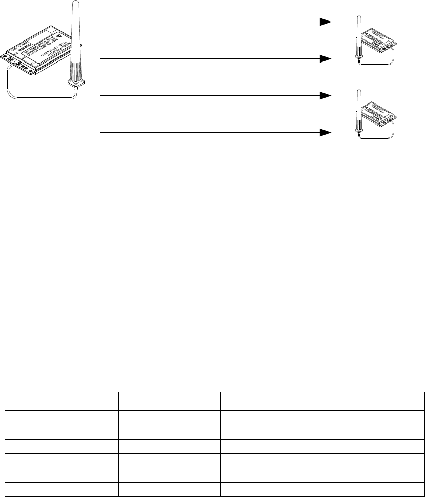
14
one and then it outputs a successive completion response (P0) to its terminal equipment.
When the remote receiver modems receive the transmitted data successfully, they output
the data to their terminal equipments normally and do not return ACK packet. Once a valid
data packet has been received correctly by a receiver modem, rest of data received during
any subsequent retransmissions are discarded and not output to its terminal equipment.
Sender Modem Remote Modem
Figure 3–3: Broadcast Transmission
3.2.3 Transmit Command and Receive Header
Six transmit commands can be used in packet transmission mode . Both text and binary
data can be sent directly from modem-to-modem or sent through a third FDL01TU modem
configured as a repeater. The receiver modem automatically determines the transmitted
data format and communication path from the information in the received packet header.
Refer to the table below for a list of the transmit commands and the corresponding header
component.
Transmit Command
Receive Header
Function
TXT RXT
Text data transmission
TBN RBN
Binary data transmission
TXR RXR
Text data transmission via repeater
TBR RBR
Binary data transmission via repeater
TX2 RX2
Text data via two repeaters
TB2 RB2
Binary data via two repeaters
Table 3–5: Transmit Commands and Receive Headers
Data Transmission
Retransmission
Retransmission
Retransmission
・
・
・
End

15
The following list shows each command’s syntax as issued at the sender terminal
equipment and the response displayed at the receiver terminal equipment when the packet is
received.
1. Direct Text Data Transmission
transmit:
@
TXT [destination address]{source address}[message]
receive: RXT [source address][message]
CR/LF
2. Direct Binary Data Transmission
transmit:
@TBN[destination address]{source address}[message length][message]
CR/LF
receive: RBN [source address][message length][message]
CR/LF
3. Text Data Transmission through Repeater
transmit:
@TXR [repeater address][destination address]{source address} [message]
CR/LF
receive: RXR [repeater address][source address][message]
CR/LF
4. Binary Data Transmission through Repeater
transmit:
@
TBR [repeater address][destination address]{source address}
[message length][message]
CR/LF
receive: RBR [repeater address][source address][message length][message]
CR/LF
where {source address} is optional, used in RS485 mode set by serial communication
cable 12 pin.
The following list defines the parameters and symbols used in the commands above:
@
= command header
CR/LF
= carriage return + line feed
destination address = address of modem to receive the message (000 to 239)
source address = address of modem sent the message (000 to 239)
repeater address = address of the repeater modem (000 to 239)
message length = number of bytes in message
message = information data (255 bytes or less)
In the text data transmission, the message is considered to be
terminated when the CR/LF code appears in it. No data after that will
be transmitted. When the CR/LF code contains in a message, use the
binary data transmission command.
CAUTION

16
3.3
Headerless stream Mode
3.3.1 Operation in the headerless stream mode
The headerless stream mode is a specific transmission mode to set transmission data
without the packet header, employing the protocol of the packet transmission mode.
Parameters such as receiver or repeater addresses are set either by the memory
register or by the command. A transmission data packet is automatically terminated by the
specific character (terminator). Command responses (P1, P0) are not output.
In the headerless stream mode, since the transmission data is no longer to be issued as
the transmission command. At the end to end of the wired link, existing upper layer
application protocol can be used without awareness of the wireless link protocol.
This mode can communicate with the normal packet transmission mode interactively.
This mode cannot be used in the RS485 mode.
3.3.1.1 Format of the headerless stream mode
In the headerless stream mode, no response (P1, P0) following the transmission
command is output. Instead of outputting the receive header or the CR/LF code, the
specific characters (terminator) is output which separates data to a transmission packet at
the sender end.
Since the transmission packet contains the sender’s address, data format (text or binary
mode) and the repeater address, the headerless stream mode is compatible with the
normal packet transmission mode and the interactive communication can be performed
between them.
The transmission and receiving formats in the headerless stream mode are as follows.
1. Packet transmission mode (for the reference below)
Sender: @TXT002HELLO
CR/LF
-> Receiver: RXT001HELLO
CR/LF
2. Headerless stream mode (when terminator is
CR/LF
)
Sender: @HELLO
CR/LF
-> Receiver: HELLO
CR/LF
3. When the receiver is in the packet transmission mode (text mode)
Sender: @HELLO
CR/LF
-> Receiver: RXT001HELLO
CR/LF
4. When the receiver is in the packet transmission mode (binary mode)
Sender: @HELLO
CR/LF
-> Receiver: RBN001HELLO
CR/LF CR/LF
5. When sender is in the packet transmission mode
Sender: @TXT002HELLO
CR/LF
-> Receiver: HELLO
When the receiver is in the packet transmission mode, be careful
about the terminator. For details, refer to REG23 of p.27 M
EMORY
R
EGISTER
D
ESCRIPTION
.

17
The difference between the text mode and the binary mode does
not matter in the headerless stream mode.
3.3.1.2 Commands for the headerless packet mode
The same command as used in the packet transmission mode can be used, but the
following commands which attempted transmission cannot be used.
TXT, TXR, TBN, TBR, RPT, RTY.
3.3.1.3 Repeater in the headerless packet mode
The repeater also can be used in the headerless stream mode. The repeater address is
set with the memory register or the PAS command. The repeater itself no needs to be
in the headerless stream mode.
Set REG18:bit 5 whether the repeater is used or not. The address of the repeater is set
using REG08 and REG09 or PAS command.
3.4
Power Down Mode
The FDL01TU has three power down modes. Select the mode according to the power
supply operating conditions such as battery powered application.
(1) Active Mode
This mode is not the power down mode but always capable of transmitting and receiving
data. The modem is in the active mode when the power is turned on.
The current consumption is 110 mA maximum in this mode.
(2) RF Block Power Down Mode
This mode shuts down the power supply of the RF circuit block, where only the control
(logic) circuit is activating. Since the control circuit is in operation, the setting of memory
registers are retained. When the modem returns to the Active mode, it can continue its
operation since the register value is retained. Furthermore, functions such as referencing
and setting memory registers can be used in this mode.
This mode is invoked by the following commands.
ROF command: to become the RF block power down mode
RON command: to return to the Active mode
The current consumption is about 35 mA in this mode.

18
3.5
Frequency Grouping
3.5.1 Frequency Allocation
The FDL01TU can operate on 76 available frequencies between 2403 MHz and 2480 MHz
with 1 MHz separation between each frequency. See the table below for the exact
frequency assignments.
Freq.No. Freq.(MHz) Freq.No. Freq.(MHz)
0 2403.328 45 2449.408
1 2404.352 46 2450.432
2 2405.376 47 2451.456
3 2406.400 48 2452.480
4 2407.424 49 2453.504
5 2408.448 50 2454.528
6 2409.472 51 2455.552
7 2410.496 52 2456.576
8 2411.520 53 2457.600
9 2412.544 54 2458.624
10 2413.568 55 2459.648
11 2414.592 56 2460.672
12 2415.616 57 2461.696
13 2416.640 58 2462.720
14 2417.664 59 2463.744
15 2418.688 60 2464.768
16 2419.712 61 2465.792
17 2420.736 62 2466.816
18 2421.760 63 2467.840
19 2422.784 64 2468.864
20 2423.808 65 2469.888
21 2424.832 66 2470.912
22 2425.856 67 2471.936
23 2426.880 68 2472.960
24 2427.904 69 2473.984
25 2428.928 70 2475.008
26 2429.952 71 2476.032
27 2430.976 72 2477.056
28 2432.000 73 2478.080
29 2433.024 74 2479.104
30 2434.048 75 2480.128
31 2435.072
32 2436.096
33 2437.120
34 2438.144
35 2439.168
36 2440.192
37 2441.216
38 2442.240
39 2443.264
40 2444.288
41 2445.312
42 2446.336
43 2447.360
44 2448.384

19
3.5.2 Frequency Group Operation
The FDL01TU can operate on a fixed frequency or on any frequency in a set of
frequency group.
Multiple FDL01TU systems can be use different frequency groups and operate in the
same area without mutual interference between the systems. When the RF environment is
relatively clean, wireless channel links can be made on a fixed, clear frequency (no
interference) by using Grouping Method A. In less than ideal RF environments, it is better
to use multiple frequencies method in the frequency group (Grouping Method B through
G, multi-Access function). Since the modem searches clear frequency in the group, it
overcomes multipath fading and interference problems and establishes wireless
communications.
On the down side, wireless link establishment delays will become longer when using the
frequency group function (multi-access function) because the additional time is
required for searching the channels in the group with transmitting and receiving the packet
on the both end of the modem. The average connection delay will increase and the number
of systems that can operate independently in the same area will decrease as the number of
frequencies per group increases. Select the best grouping method for your application.
3.5.3 Grouping Methods
The frequency grouping method and group number are set using memory register
REG06.
Method
Group Numbers
Frequencies
per Group
A 0
to
75
1
B 0
to
37
2
C 0
to
24
3
D 0
to
18
4
E 0
to
11
6
F 0
to
8
8
G 0
to
5
12
Table 3–7: Frequency Grouping Methods and Group Numbers
20

21
4
SECTION
4 FUNCTION CONTROL METHODS
22
4.1
Interface
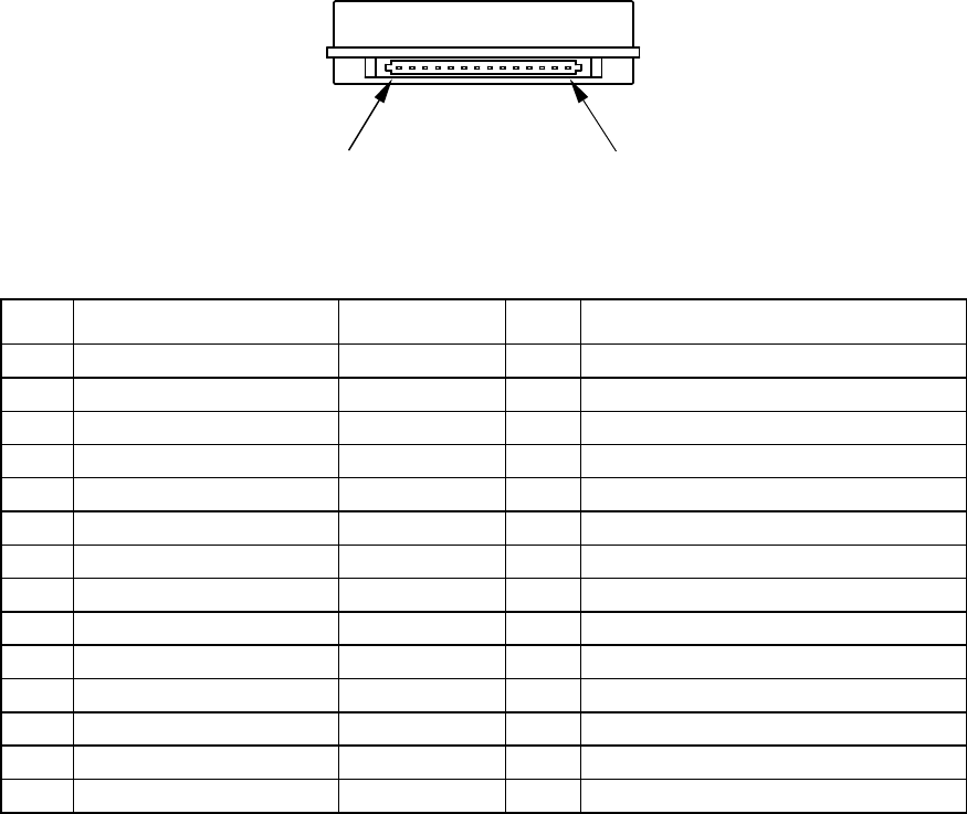
4.1.1 Pin Assignment
The figure below shows the pin location of the serial communication connector,
following the DCE (Data Communication Equipment) specification.
Figure 4–1: Serial Communication Connector Location
Pin
Name Abbreviation
I/O Function
1
Carrier Detect Out DCDO output
carrier detect output
2
Receive Data RxD output
received data output
3
Transmit Data TxD input
transmit data input
4
Data Terminal Ready DTR input
terminal ready
5
Signal Ground GND –
signal ground
6
Data Set Ready DSR output
modem ready
7
Request To Send RTS input
receive stop/resume request
8
Clear To Send CTS output
transmit stop/resume request
9
Carrier Detect In DCDI input
ring indicator input
10
Power Supply VCC –
2.7V to 3.3V DC
11
Modem Shutdown POWER_ON
input
Power On control
12
RS485 Enable 485ENB in/out
RS485bus Tx Enable at 485mode
13
Load Default Parameter
/INIT input
Load default parameter when low
14
Reserved Reserved –
Reserved
Table 4–1: Pin Descriptions
1. The serial communication connector’s pin of the modem is defined as the DCE
specification, where transmission indicates input and reception indicates output.
2. Pin 12 is for tri-state control for RS485 driver (CMOS - RS485 level converter) which
will be externally mounted. When the power is turned on or reset, this pin is configured
as an input pin to read the operation mode in the interface. When it is pulled down, the
operation becomes the RS485 mode, and when it is pulled up (or leave open) the
operation becomes the RS232C mode. Since this pin becomes to configure the output
pin after reading the operation mode at the initialize state, never connect it directly to
VCC or GND. This pin is internally pulled up with 470 k ohm.
3. Pin 13 is internally pulled up with 100 k ohm.
4. The input pin tolerates 5 V input (5 V tolerant specification). When the user’s system is
of 5 V, it is possible to interface with a such system.
# 1
# 14
23
5. Pin 11 can be used as the hardware reset. Since the input pin is at high impedance,
never fail to tie the input level.
6. It is no problem if Pins 12, 13 and 14 are leaved open.
7. Since the interface is CMOS structure circuit, it is recommended to take a remedy
against ESD problem (e.g. surge absorber; VRD series, made by Ishizuka Denki).
4.2
Serial Interface Setting
For connecting the FDL01TU modem with an external terminal equipment, RS232C is
appropriate for 1 to 1 topology. And set the RS485 mode to make RS485 multi-dropping
topology for multiple equipment connection. Interface configuration can be made with Pin
12 (/RS485ENB) of the serial communication connector.
To configure the RS485 mode, pull down Pin 12 with 10k ohm register. In this case, do
NOT connect this pin DIRECTLY to the GND. This is because in RS485 mode, this pin
will be as an output pin, after the initialization completes, to control the output buffer of the
RS485 driver IC chip. As for the RS232C interface, no connection is required because it is
pulled up inside.
Since the interface level of the FDL01TU modem is CMOS, the level conversion circuit
must be provided outside for connecting it with the RS232C or RS485 interface. For an
example of the level conversion circuit, see p.64 C
ONVERSION
C
IRCUIT
.
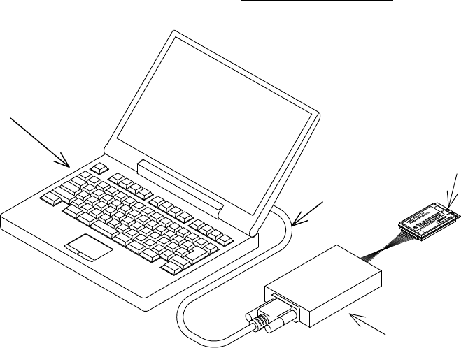
Figure 4–1: Connection Example to PC
Converter
PC
RS
-
232C
FD
L modem

24
4.3
Terminal Software Setup for Memory Register Control
Communication or terminal software is necessary to set the memory registers. Nearly any
PC communication software can be used. Launch the communication software and set the
terminal’s communication parameters as shown below. Refer to your specific
communication software instructions how to set these parameters.
bit rate: 9600 bps
data length: 8 bits
stop bits: 1 bit
parity bit: none
flow control: none
local echo: yes
terminator: carriage return + line feed
4.4
Memory Register Setting
Memory registers set the operation mode and communication parameters of the modem
and retain them in memory. All of the settings of the modem are made by these memory
registers.
Since the memory register is based on rewritable non volatile memories, these memories
can be readily rewritten by external terminal equipment such as PC and their contents will
be kept even after the power is turned off. This non volatile memory can be rewritten about
1 million times.
4.4.1 Memory Register Referencing and Setting
Memory registers are referenced and set with the REG command. (For more information,
refer to REG section at p.43 C
OMMAND
S
ET
D
ESCRIPTION
)
Example procedure:
1. To view the current value of register 00, enter:
@
REG00
CR/LF
2. Modem responds with 00H
CR/LF
(REG00 is assumed to be 00H in this case and
varies in each setting case)
3. To set register REG00 to 0FH, enter:
@
REG00:0FH
CR/LF
4. Modem responds with “P0”
CR/LF
5. Enter “
@
RST
CR/LF
” or cycle the modem power, to activate new values
@
= command header (specify following characters are command)
CR/LF
= Terminator (carriage return + line feed)
When rewriting the modem’s memory registers, do not turn the
modem’s power off until the modem returns “P0” response. If the
power is interrupted before “P0” is returned, the memory contents
may be lost or corrupted and the modem operation will be
unpredictable.
CAUTION

25
If the memory contents are lost or corrupted, they can be restored to
original default settings by reinitializing them. (See the section below
titled p.25 M
EMORY
R
EGISTER
I
NITIALIZATION
)
Input character arrays of commands quickly and sequentially.
Too slow input (taking more than 5 seconds in the initial setting)
results in command error.
4.4.2 Memory Register Initialization
The memory registers can be restored to the factory default values at any time by using
one of the following two methods.
1) Memory Register Initialization by hardware:
Use either methods stated below, in which the modem attempts to read Pin 13
(/DefParam) of the serial communication connector at the startup and starts initializing
the memory registers when it is “L”.
Method 1. Set “L” level to Pin 13 (/INIT) of the serial communication connector
with the power turned off. When the power is re-supplied, the memory registers
are initialized and the modem starts operation in the factory default state.
Method 2. Set “L” level to Pin 13 (/INIT) of the serial communication connector
while the power turned on. In this state, force “L” to Pin 11 (POWER ON) of the
serial communication connector more than 1ms, then return the level to “H”. The
modem once becomes the Shutdown mode and returns to Active mode. Since this
sequence is the same as the reset, the memory registers are initialized and the
modem starts operation in the factory default state.
2) Memory Register Initialization by Command:
1. With the modem power is on and the communication software running, enter “
@
INI
CR/LF
”
at the terminal prompt.
2. The modem responds with “P0” response
and immediately begins to operate using
the initialized factory default state.
While initializing the memory registers, do not turn the modem’s
power off. It take about 1 sec. to initialize the memory registers.
CAUTION
CAUTION
26
4.5
Command Control
Some FDL01TU parameters can be changed by issuing commands from the terminal
equipment. Various applications can be supported with the flexibility that command control
offers.
Command Entry
•
When a command is issued to the modem from the terminal equipment, a command
header (one byte character) should be used the modem to acknowledge the command
from ordinary data. The command header is initially set to “
@
” (40H) but can be
changed to another character by changing the value stored in the memory register
REG10.
•
Commands must use all upper case letters (A to Z). The modem does not recognize
lower case letters (a to z) in commands.
•
A two byte terminator (carriage return (0DH) + line feed (0AH)) is used to terminate a
command. “
CR/LF
” shows the terminator in this manual. PC can send this two byte
character with pressing ENTER key once using a communication software. But some
setting is necessary in the software.
•
The modem immediately executes a command once it’s recognized. If the command
requires a response, the modem returns the response to the terminal equipment
when its internal processing is completed.
The following is an example of a command entry and response:
@BCL
CR/LF
:command issued from the terminal equipment
P0
CR/LF
: successive completion response is returned

27
5
SECTION
5 MEMORY REGISTER DESCRIPTION

28
5.1
Memory Register Description
The FDL01TU modem contains 28 memory registers which are used to control and store
communication parameters and operation mode settings. After rewriting new register
settings, the power must be cycled, a hardware reset asserted, or a software RST
command is issued to validate the new settings.
The following table briefly lists each register, register function and default value:
Register
Function Default Value Meaning
REG00
Local Station Address 000
address 0
REG01
Local Station Group Address 240
address 240
REG02
Destination Address 000
address 0
REG03
Reserved F0
H F0H
REG04
ID Code 1 00
H address 0
REG05
ID Code 2 00
H address 0
REG06
Frequency Group C00
see text
REG07
Packet Interval 05
H 5 ms
REG08
Repeater1 Address A00
not use
REG09
Repeater2 Address A00
not use
REG10
Command Header 40
H character @
REG11
Retransmission Count 32
H 50 count
REG12
Roaming Threshold 50
H -80dBm
REG13
Buufer Data Timeout 1E
H 30 s
REG14
Command Input Timeoutl 32
H 5 s
REG15
Command Recognition Interval 00
H 0 s
REG16
Terminator 1 0D
H CR
REG17
Terminator 2 0A
H LF
REG18
Communication Setting 1 8C
H see text
REG19
Communication Setting 2 00
H see text
REG20
Serial Interface Setting 1 05
H see text
REG21
Serial Interface Setting 2 09
H see text
REG22
Serial Interface Setting 3 00
H see text
REG23
Serial Interface Setting 4 00
H see text
REG24
Miscellaneous Settings C0
H see text
REG25
Miscellaneous Settings 40
H see text
REG26
Data Input Timeout 00
H not use
REG27
Reserved 00
H -
Table 5–1: Memory Registers
Suffix ‘H’ of each default value denotes HEX radix expression in the value.

29
REG00: Local Station Address [default value: 000]
•
Sets the local station address. Valid values are 000 to 999.
•
This value is inserted in the “source address” field in the transmitted packet header.
•
If the address check function is enabled (REG18) in the receiving modem, the
modem can receive the packet which header contains destination address
information identical to REG00.
REG01: Local Station Group Address [default value: 240]
•
Sets the local station global address of the modem. Valid values are 240 to 254.
•
When plural modems are connected by RS485 multi-dropping topology, commands
can be issued to multiple modems simultaneously by setting all connected modems to
the same group address. This is the group addressing.
•
This group addressing allows to handle multiple multi-dropped modems as if they
were one modem.
REG02: Destination Address [default value: 000]
•
This address is used in the data transpalent mode and headerless stream mode.
•
Valid values are 000 to A23(1023).
REG03: Reserved [default value: F0H]
•
The FDL01TU does not use this register. Keep the default value as it is.
REG04: ID Code 1 [default value: 00H]
•
Used with ID code 2 (REG05), set the ID code. Valid values are 000 to 255.
Together with ID code 2, up to 65535 ID codes can be set.
•
The ID code identifies the group of the modems works in the same group. The ID
code is used to prevent erroneous connection with other systems and for
communication security.
•
Before transmission, radio data packets are scrambled using a pseudo-random data
sequence generated with this ID code as the seed. During reception, the original data
is restored by de-scrambling it with the pseudo-random data sequence. The modems
with different ID codes cannot communicate with each other.
REG05: ID Code 2 [default value: 00H]
•
Used with ID code 1 (REG04), set the ID code. Valid values are 000 to 255.
Together with ID code 1, up to 65535 ID codes can be set.
•
In case plural modems are used as a single system, always set the same ID code for all
modems and repeaters.

30
REG06: Frequency Group [default value:C00]
•
Refer to p.18 F
REQUENCY
G
ROUPING
in Section 3, for a detailed description of the
frequency operation modes.
Method
Group Numbers
Frequencies
per Group
A 0
to
75
1
B 0
to
37
2
C 0
to
24
3
D 0
to
18
4
E 0
to
11
6
F 0
to
8
8
G 0
to
5
12
Table 5–2: Grouping of Frequency
REG07: RS485 Packet Interval [default value: 05H]
•
In the packet transmission mode with the RS485 mode is used, sets the interval
between response and/or received data which output from the modem to RS485 line.
•
Be able to set 0 to 254 ms at increment of 1 ms. 255ms is not allowed. The default
value is 5 ms.
•
Set this interval to a larger value than the receiving interval set by REG14.
•
Suitable setting of this interval avoids the data collision possibility of RS485 line.
REG08: Repeater 1 Address [default value: A00]
•
When a repeater is used, set the repeater1 address to pass through.
REG09: Repeater 2 Address [default value: A00]
•
When second repeater is used, set the repeater2 address to pass through.
REG10: Command Header [default value: 40H]
•
Sets the character that identifies the start of a command.
•
The default is character “@” (40H).
•
When this character is input from the terminal equipment after no character is
received for the command recognition interval (REG15) or longer, subsequent
input character is recognized as a command for the modem.

31
REG11: Retransmission Count [default value: 32H]
•
Sets the maximum number of packet retransmission attempts. Valid values are 000
to 255.
•
When retransmission exceeds the retransmission count (retransmission count plus
one), the modem outputs an error response to the terminal equipment.
REG12: Roaming Threshold [default value: 50H]
•
At the time to set the frequency roaming (REG19:bit 2 is 1), set the receiving
strength threshold of the radio beacon which starts scanning frequency.
•
Set the value of the desired radio beacon strength threshold represented in dBm
excluding the minus sign, e.g., set to “080” to search the next master station when the
radio beacon strength becomes below –80 dBm.
REG13: Buffer Data Timeout [default value: 1EH]
•
Valid values are 000 to 255, representing seconds in 1 s increments.
REG14: Command Input Timeout [default value: 32H]
•
Sets the character input timeout interval for command input. It is used as the
timeout between the command header and the character following it and between
each character of the command.
•
At the timeout, the modem operation transits from command-input-state to data-
wait-state.
•
Valid values are 000 to 255, representing tenths of seconds in 0.1 second increments.
(Set an integer value equal to ten times the number of seconds desired.)
•
A setting of 000 disables this timeout function
REG15: Command Recognition Interval [default value: 00H]
•
When a message data contains a command header character (in case of binary data
or data in two-byte Chinese characters), data following the command header
character will be interpreted as a command, the message does not transmit properly.
•
Sets the necessary vacant duration time interval to discriminate between ordinary
data character and a command header character. Input a command after a longer
interval than time interval setting.
•
Valid values are 0.1 to 25.4 sec., representing tenths of seconds in 0.1 second
increments. (Set an integer value equal to ten times the number of seconds desired.)
•
When set to 000, the command header is recognized at any time, and when set to
255, all command header character are ignored.
32
REG16: Terminator 1 [default value: 0DH]
•
Set an arbitrary 1 byte terminator. In case of a 2-byte terminator, set the first byte
character of the terminator.
REG17: Terminator 2 [default value: 0AH]
•
Set another arbitrary 1 byte terminator. In case of a 2-byte terminator, set the last
character of the terminator .
REG18: Communication Setting 1 [default value: 8CH]
Bits 7 – 6: Protocol
bit 7
bit 6
Setting
0 0 Data transpalent mode
0 1 Reserved
1 0 Packet transmission mode
1 1 Headerless stream mode
Table 5–7: Protocol
Bits 5: Reserved
•
The FDL01TU does not use this register. Keep the default value as it is.
Bit 4 Transmission format
0
transmit in the text form (default value)
1
transmit in the binary form
Table 7–4 Transmission format
•
Selects the transmission format. When data are transmitted to the destination
station which is set to the normal packet transmission mode, output text format
(RXT, RBN) from the receiver modem (destination station) differs depend on this
setting.
•
This setting does not effect in the receiver modem set as headerless stream mode.
Bits 3 – 2 Terminator Setting
bit 3 bit 2
setting
0 0
two kinds of arbitrary 1 byte code (REG16, REG17)
0 1
arbitrary 1 byte code (REG16) + a wild card (any character)
1 0
arbitrary 2 byte code (REG16 + REG17)
1 1
carriage return (CR) + line feed (LF) (default value)
Table 7–5 Terminator setting
33
•
Sets the terminator to identify the breakpoint of a packet. The modem transmits data
considering this character as the breakpoint of a packet.
•
In case of using an arbitrary terminator, set it to REG16 and 17.
Bit 1: Source address check
0
Inhibit source address checking (default value)
1
Activate source address checking
Table 5–4: Source Address Check Settings
•
When the source address checking is active and the source address in the
received packet header does not match the destination address setting (REG02),
the data is discarded (data cannot be received).
Bit 0: Destination address check
0
Inhibit destination address checking on receipt (default)
1
Activate destination address checking on receipt
Table 5–5: Destination address check
•
When the destination address checking is active and the destination address in
the received packet header does not match the received modem’s local station
address (REG00), the data is discarded (data cannot be received).
REG19: Communication Setting 2 [default value: 00H]
Bit 7: Reserved
•
The FDL01TU does not use this register. Keep the default value as it is.
Bit 6: Diversity Reception
0
Disable diversity reception (default value)
1
Enable diversity reception
Table 5–6: Diversity Reception Settings
•
Enable/disable diversity reception.
•
To enable diversity reception, set this bit to 1.
•
Enabling diversity reception with only one antenna connected may degrade the
reception performance.
Bit 5: Broadcast Transmission Reception
0
Enable broadcast transmission reception (default value)
1
Disable broadcast transmission reception
Table 5–7: Broadcast Reception Settings
34
•
Enable/disable reception of broadcast transmission in packet transmission mode
(Mode 3 and 5).
Bit 4: Antenna selection
0
Antenna is fixed to A (default value)
1
Antenna is fixed to B
Table 5–8: Antenna Selection
•
At the non-diversity reception, decide the antenna terminal.
Bit 3: Extended reception
0
Disable extended reception (default value)
1
Enable extended reception
Table 5–9: Extended reception
•
Contention type communication in packet transmission mode (including the
headerless stream mode) may cause repetitive retransmission when two modems
are in transmission state in identical timing. This results in the decrease of response
rate or the transmission failure.
•
This extend reception function solves such problems as above. The data packet
received during carrier sensing are received first by interrupting the on-going
transmission operation.
Bit 2: Receiving frequency change
0
Regularly change frequency within a group while waiting (default value)
1
Fix the frequency to wait while data can be regularly received.
Table 5–10: Receiving frequency change
•
Set the changing method of receiving frequency in packet transmission mode. Sets
roaming function with combining bit 1.
Bit 1: Beacon transmission
0
No transmission until transmission command is requested (default)
1
Enable regular beacon transmission.
Table 5–11: Beacon Transmission
•
Enable or disenable beacon transmission in packet transmission mode.
•
Set roaming function with combining bit 2.
Bit 0: Reserved
•
The FDL01TU does not use this register. Keep the default value as it is.
35
REG20: Serial Interface Setting 1 [default value: 05H]
Bit 7: Data Length
0
8 bit data bytes (default value)
1
7 bit data bytes
Table 5–13: Data Length Settings
Bit 6: Parity Bit
0
No parity bit (default value)
1
Parity bit
Table 5–14: Parity Settings
Bit 5: Even/Odd Parity
0
Even parity (default value)
1
Odd parity
Table 5–15: Odd/Even Parity Settings
•
Invalid when bit 6 is set to 0, without parity.
Bit 4: Stop Bit
0
1 stop bit (default value)
1
2 stop bits
Table 5–16: Stop Bit Settings
Bits 3 – 0: Baud rate setting
Bit 3
Bit 2
Bit 1
Bit 0
Setting
0 0 0 0 300 bps
0 0 0 1 600 bps
0 0 1 0 1200 bps
0 0 1 1 2400 bps
0 1 0 0 4800 bps
0 1 0 1 9600 bps (default)
0 1 1 0 19200 bps
0 1 1 1 38400 bps
1 0 0 0 Reserved
1 0 0 1 Reserved
1 0 1 0 Reserved
1 0 1 1 Reserved
1 1 0 0 57600 bps
1 1 0 1 115200 bps
1 1 1 0 230400 bps
1 1 1 1 Reserved
Table 5–17: Baud Rate

36
REG21: Serial Interface Setting 2 [default value: 09H]
Bits 7 – 4: Reserved
•
The FDL01TU does not use this register. Keep the default value as it is.
Bit 4: Command Header
0
Use REG 10 character
1
Use Break signal
Table 5–16: Command Header
Bit 1: Flow Control
0
Software flow control (default value)
1
Hardware flow control
Table 5–18 Software/Hardware Flow Control Settings
•
Selects the flow control method. This setting must match the connected terminal
equipment’s setting.
•
Hardware flow control uses the two control lines RTS and CTS. When using with
the RS485 interface, be sure to set to 0.
•
Software flow control uses XON and XOFF codes.
Bit 0: Flow Control 2
0
disable flow control
1
enable flow control
Table 5–31: Flow Control 2 Settings
•
Enable or disable flow control between the terminal and FDL01TU modem connected
through the RS-232C serial interface.
•
This function should normally be enabled, otherwise buffer overflow can occur and
data may be lost.
REG22: Serial Interface Setting 3 [default value: 00H]
Bit 7: Enable and Disable Reception
0
Enable reception at the initial state (default value)
1
Disable reception at the initial state
Table 5–19: Enable/Disable Reception
•
The initial state is in reception enable. Depending on an usage of the modem, the
initial state of the modem may be better in the reception disable state. In such a case,
use this setting.

37
•
Issue the REN command to enable reception.
Bit 6: Reserved
•
The FDL01TU does not use this register. Keep the default value as it is.
Bits 5 – 4: DCD (Data Carrier Detect)
Bit 5
Bit 4
Setting
0 0
Ignore DCD input; DCD output always ON (default value)
0 1
Ignore DCD input; DCD output ON at connection, OFF at disconnection
1 0
Remote modem’s DCD (IN) is transferred to local modem DCD (OUT).
(DCD Output = OFF at reset state)
1 1
Remote modem’s DCD (IN) is transferred to local modem DCD (OUT)
(DCD Output = ON at reset state)
Table 5–20: DCD Settings
Bits 3 – 2: DTR/DSR
Bit 3
Bit 2
Setting
0 0
Ignore DTR input; DSR output always ON (default value)
0 1
Ignore DTR input; DSR output ON at connection, OFF at disconnection
1 0
Remote modem DTR is transferred on local modem CTS (CTS = OFF at
reset state)
1 1
Remote DTR is transferred on local modem CTS (CTS = ON at reset
state)
Table 5–21: DTR/DSR Control Settings
Bits 1 – 0: Reserved
•
The FDL01TU does not use this register. Keep the default value as it is.
REG23: Serial Interface Setting 4 [default value: 00H]
Bit 7 : reserved
•
The FDL01TU does not use this register. Keep the default value as it is.
Bit 6 : Transmission buffer clear
0
Data of the transmission buffer is kept after disconnection (default value)
1
Transmission buffer is cleared when the link is disconnected.
Table 5–38 Transmission buffer clear
•
Determine to clear or not to clear data stored in the transmission buffer in the data
transparent mode when the link is reconnected.
Bit 5 : reserved
•
The FDL01TU does not use this register. Keep the default value as it is.
38
Bit 4 : CR/LF addition/deletion
(1) Setting at the headerless stream mode
0
does not add CR/LF code to the received data (default value)
1
adds CR/LF code to the received data
Table 7–6: Addition of CR/LF code
•
In the headerless stream mode, setting is made whether the CR/LF character is
added to the received data or not.
•
In the communication between the modems set to the headerless packet mode, this
setting is invalid because the terminator is originally added to the transmit data.
However, when a packet is received from the modem in the packet transmission
mode, there is no addition of the CR/LF terminator. In this case, set this bit to 1.
Then the received packet is output with the CR/LF character is added.
(2) Setting at the packet transmission mode
0
adds the CR/LF to the received data (default value)
1
does not add the CR/LF to the received data
Table 7–7: Deletion of CR/LF character
•
In the packet transmission mode, setting is made whether the CR/LF character is
added to the received data or not.
•
At the receiver modem (set to the packet transmission mode), the sender (set to the
headerless stream mode) side terminator (CR/LF character as default) plus
packet transmission mode terminator (CR/LF) are output. To avoid such
redundant outputs, set this bit of the modem in the normal packet transmission
mode to 1.
Bit 3: reserved
•
The FDL01TU does not use this register. Keep the default value as it is.
Bit 2: RS485 collision avoidance regular interval output
0
No C/R code output for collision avoidance (default value)
1
Regularly output C/R code for collision avoidance
Table 5–23: C/R Code Regular Interval Output
•
Sets whether the collision avoidance function is used or not, together with bit 1.
•
When this bit is set to 1, responses or data will be output to RS485 line if there are
such responses or data exist in the buffer at the timeout of the RS485 Packet
Interval (REG07). If there are no such responses or data exist in the buffer, the
C/R code (0Dh) is compulsorily output.
•
The effective use of this function helps to shift the output timing of multi-dropped
modems on RS485 line. Eventually it avoids the data collision on the RS485 line.

39
•
To use this function, set REG23:bit 1 of all RS485 multi-dropped modems to 1. And
set all the RS485 Packet Interval (REG07) to different values more than 1.5 bytes
each. Further set this bit of the modem, the RS485 Packet Interval is set to the
longest, to 1.
Bit 1: RS485 collision avoidance
0
Invalid collision avoidance function (default value)
1
Use collision avoidance function
Table 5–24: Collision Avoidance Function
•
Sets to decide whether to use the collision avoidance function or not, together with
bit 2.
•
When modem tried to output a response or the received data, the modem outputs
only if RS485 line is available at the timeout of RS485 Packets Interval (REG07).
When RS485 line is not available at the timeout, the modem waits for a line becomes
available and starts re-measurement of its packet interval.
•
Set to 1 makes it unable to output neither response nor the received data, unless
other modem(s) outputs any data to the RS485 line and interval time measuring
becomes effect.
•
Bit 2 is used for the purpose of resolving this problem.
Bit 0: Global addressing command response
0
No P0 response to global addressing command (default value)
1
Respond P0 response to global addressing command
Table 5–25: Global addressing command response
•
Set to decide whether to return “P0” response (including “P1” for the transmit
command) to the terminal equipment for the global addressing command
(commands for Addresses 240 to 254).
•
When the global addressing command is issued to plural modems, which are
multi-dropped and have the same global address on RS485 line, there is a possibility
causing data collision on the RS485 line. Unless the RS485 Packet Interval is
properly set. This is because all modems return the “P0” (or P1) response to the
terminal equipment simultaneously on default memory setting. Such potential
problem can be avoided by limiting the modem to output the response to the global
addressing command is only one.
40
REG24: Special Mode Settings [default value: C0H]
Bit 7 : reserved
•
The FDL01TU does not use this register. Keep the default value as it is.
Bit 6: Transmission trigger (Headerless stream mode)
0
Need trigger even if data number exceeds 255 bytes(default value)
1
Transmit without trigger when the data number exceeds 255 bytes
Table 5–26: Transmission trigger setting
•
Sets the trigger mode of the Headerles stream mode.
Bit 5 – 2: reserved
•
The FDL01TU does not use this register. Keep the default value as it is.
Bits 1 – 0: Reception protocol
Bit 1
Bit 0
Setting
0 0
Receive with the setting of REG18 bit7 to bit6(default value)
0 1
Receive with the packet transmission mode
1 0
Receive with the headerless stream mode
1 1
Receive with the protokol of the received packet
Table 5–21: Reception protocol
REG25: Special Mode Settings 2 [default value: 40H]
Bit 7 – 3: reserved
•
The FDL01TU does not use this register. Keep the default value as it is.
Bit 2: Group address settings
0
Normal group address (240 to 254)(default value)
1
Extended group address (1000 to 1023)
Table 5–29: Group address setting
Bit 1: Address response
0
No response the address when the link is connected or disconnected
(default value)
1
Response the destination address when the link is connected or
disconnected.
Table 5–29: Address response

41
Bit 0: Route finding
0
According to the memory registers (default value)
1
Trace the received packet.
Table 5–29: Settings of the route
REG26: Data input timeout [default value: 00H]
•
Sets the vacant duration time interval to recognize as the end of the message data
input in the headerless stream mode.
REG27: Reserved [default value: 00H]
•
The FDL01TU does not use this register. Keep the default value as it is.
42

43
6
SECTION
6 COMMAND SET DESCRIPTION

44
6.1
Command Set Description
This section provides a description of each command available in the FDL command set.
The table below lists each command and it applicability in each operation mode.
Command
Function
1
ARG
Reference All Memory Resisters
2
BCL
Clear Transmit and Receive Buffers
3
CON
Connect Wireless Link
4
DAS
Reference and Set the Destination Address
5
DBM
Read Signal Strength
6
DCN
Disconnect Wireless Link
7
FRQ
Reference and Set Frequency Group
8
INI
Initialize All Memory Resisters
9
ODA
Disable Received Data Output
10
OEN
Enable Received Data Output
11
PAS
Reference and Set Repeater Address
12
RDA
Disable Wireless Reception
13
REG
Reference and Set Memory Resisters
14
REN
Enable Wireless Reception
15
RID
Display Received Serial ID
16
RNO
Reference and Set Retransmission Count
17
ROF
RF Circuit Block Power Down
18
RON
RF Circuit Block Power Up
19
RST
Reset
20
SAS
Reference and Set Local Station Address
21
STS
Read Status
22
TBN
Transmit Binary Data
23
TBR
Transmit Binary Data Through Repeater
24
TID
Display Local Station Serial ID
25
TXR
Transmit Text Data Through Repeater
26
TXT
Transmit Text Data
27
VER
Reference Version Information
Table 6–1: Command to Mode Availability
The symbols used in this section have the following meaning:
> : Input character from the terminal equipment to the modem
< : Output from the modem to the terminal equipment
@
: Command header
CR/LF
: Terminator (carriage return + line feed)
[ ] : Required input parameter/s Be sure to input.
( ) : Optional input parameter/s May be omitted
{} : 485 mode local station address (REG00). Be sure to
input at 485 mode
In the Syntax and Response segments of the following command descriptions the
terminator symbol (
CR/LF
)
has been omitted for clarity.

45
ARG Reference All Memory Registers
Syntax
ARG{Local Station Address}
Local Station Address : local station address for 485 mode (000 to 999).
Response
All settings are indicated (REG00 to REG27)
N0: command error (Except 485 mode)
Function
Recalls the contents of all 28 memory registers.
Example
>
@
ARG
CR/LF
: Recall the contents of all the memory registers
<REG00 : 001
CR/LF
: Consecutive output of register contents
<REG01 : 240
CR/LF
: Register values output in hexadecimal codes
<REG02 : 002
CR/LF
<REG03 : F0H
CR/LF
|
|
<REG26 : 00H
CR/LF
<REG27 : 00H
CR/LF
BCL Clear Transmit and Receive Buffers
Syntax
BCL{Local Station Address}
Local Station Address : local station address for 485 mode (000 to A22).
Response
P0 : command accepted
N0 : command error (Except 485 mode)
Function
On headerless stream mode , clears the contents of the transmit and receive
buffers of the modem.
Example
>
@
BCL
CR/LF
: clear the buffer contents
<P0
CR/LF
: command accepted
Example
>@BIV025
CR/LF
: Set the receiving (transmission) interval at 250 ms
<P0
CR/LF
: command accepted
>@BIV
CR/LF
: Refer the current value
<025
CR/LF
: 025 (25 0ms) returns
Notes
Values set by the BIV command will be lost by turning the power on or resetting.
Generally, this parameter is no need to modifying. Use with the default value.

46
CON Connect Wireless Link
Syntax
CON(destination address)
destination address : 000 to 999
Response
P0 : connection established
P1 : command received, link established
N0 : command error
N1 : connection failed – no response from destination modem
N4 : connection failed – local modem already connected to a remote
modem.
Function
Requests a wireless link connection to the remote modem in data transparent mode.
If this command is input with no destination address parameter, the destination will
be the address that was set with the REG02.
If the destination address is input, change the destination address to connect the
wireless.
Example
>
@
DAS002
↵
: set the destination address to 002
<P0
↵
: connection established
>
@
CON
↵
: request wireless connection remote station 002
<P1
↵
: connecting…
<P0
↵
: connection established
(Time-Division-Duplex communication between terminals is established.)
>
@
DCN
↵
: request disconnection of the wireless link
<P1
↵
: disconnecting…
<P0
↵
: connection established
>
@
CON003
↵
: request wireless connection to remote station 003
<P1
↵
: connecting…
<P0
↵
: connection established
>
@
CON004
↵
: request wireless connection to remote station 004
<N4
↵
: local modem already connected to a remote modem
Notes
If this command is input to designate the destination address, the destination address
set with the DAS command will be changed to set the address designated with this
command to the designation address.
DAS Reference and Set Destination Address
Syntax
DAS(set destination address)
set destination address : the desired destination address (000 to A23)

47
Response
xxx : current value (reference)
P0 : command accepted (setting)
N0 : command error
Function
References or sets the destination address of the modem connection established
with in the data transparent mode and headerless stream mode
The current DAS value can be referenced by entering the command with no
parameter.
The DAS command is used for temporary modifying destination address.
Change the value of REG02 to change the default value.
Example
>
@
DAS002
CR/LF
: set the destination address to 002
<P0
CR/LF
: command accepted
>
@
DAS
CR/LF
: reference the destination address
<002
CR/LF
: current value output (002)
Notes
This command cannot be used in packet transmission mode.
The local station address (REG00) must be set to communicate with the remote
modem. Communication cannot be established unless the addresses coincide with
each other.
This command is not arrowed to use in 485 mode.
DBM Read Signal Strength
Syntax
DBM{Local Station Address}
Local Station Address : local station address for 485 mode (000 to 999).
Response
-xxxdBm : signal strength
N0 : command error (Except 485 mode)
Function
Reads the received signal strength and outputs the value in dBm.
Higher values represent stronger signal strength and better receiving conditions.
Example
>
@
DBM
CR/LF
: read signal strength
<-78dBm
CR/LF
: signal strength is -78dBm.
Notes
The range available for measurement is –40 dBm to –100 dBm. Since the signal
strength indication has a slight error in its value, use this result for your ‘rule of a
thumb’ reference.
This command outputs the strength of last received packet.

48
DCN Disconnect Wireless Link
Syntax
DCN
Response
P0 : connection established
P1 : command received, link disconnected
N0 : command error
N1 : link disconnect failed
N4 : link is disconnected
Function
In data transparent mode, this command requests wireless disconnection from the
remote modem.
Example
>@CON002
↵
: request wireless connection to station 002
<P1
↵
: connecting…
<P0
↵
: connection established
(Time-Division-Duplex communication between terminals is established.)
>
@
DCN
↵
: request disconnection of the wireless link
<P1
↵
: disconnecting…
<P0
↵
: connection established
>
@
DCN
↵
: request disconnection of the wireless link
<N4
↵
: link is disconnected
FRQ Reference and Set Frequency Group
Syntax
FRQ(:frequency group){Local Station Address}
frequency group : combination of frequency grouping method (A to
H) and group number (00 to 75). See p.18
F
REQUENCY
G
ROUPING
more details.
Local Station Address : local station address for 485 mode (000 to A22) .
Response
xxx : current value
P0 : command accepted
N0 : command error (Except 485 mode)
Function
References or sets the frequency grouping method and group number.
The current set value is referenced by omitting the “:frequency group” parameter
This command is for temporary use only. To change the default value, change the
settings of REG06.

49
Example
>
@
FRQ
CR/LF
: reference the current grouping method and frequency
number
<F00
CR/LF
: output current value (grouping method F: group number 00)
>@FRQ:E03
CR/LF
: set grouping method to E (6 groups) and group number to
3.
<P0
CR/LF
: command accepted
Method
Group Numbers
Frequencies
per Group
A 0
to
75
1
B 0
to
37
2
C 0
to
24
3
D 0
to
18
4
E 0
to
11
6
F 0
to
8
8
G 0
to
5
12
Table 3–7: Frequency Grouping Methods and Group Numbers
Notes
Do not change this setting while the modem is being transmitted.
The maximum number of frequency groups available depends upon the selected
grouping method.
INI Initialize All Memory Registers
Syntax
INI{Local Station Address}
Local Station Address : local station address for 485 mode (000 to A22).
Response
P0 : command accepted
N0 : command error (Except 485 mode)
Function
Sets the all contents of the memory registers to the factory default values.
Example
>
@
INI
CR/LF
: initialize all memory registers
<P0
CR/LF
: command accepted
Notes
Custom settings of all memory registers are lost when this command is executed.

50
If the group address (REG01) is designated while RS485 multi-drop connection is
being made in the RS485 mode, the local station address of all modems will be
initialized to 000. Exercise care when issuing this command.
For a list of the factory default values, see the section titled p.27 M
EMORY
R
EGISTER
D
ESCRIPTION
.
ODA Disable Received Data Output
Syntax
ODA{Local Station Address}
Local Station Address : local station address for 485 mode (000 to A22).
Response
P0 : command accepted
N0 : command error (Except 485 mode)
Function
Disables output of any data received via the wireless link to the terminal
equipment.
Data received, while output is disabled, is stored in the receive buffer.
When the modem’s power is turned on (or a reset), the modem is in the state to
enable the received data output.
Example
>
@
ODA
CR/LF
: disable the output of received wireless data
<P0
CR/LF
: command accepted
(Data is not output during this period even if received.)
>
@
OEN
CR/LF
: enable the output of received wireless data.
<P0
CR/LF
: command accepted
<RXT002HELLO
CR/LF
: outputs data stored in the receive buffer
<RXT003MAIL
CR/LF
:
OEN Enable Received Data Output
Syntax
OEN{Local Station Address}
Local Station Address : local station address for 485 mode (000 to A22).
Response
P0 : command accepted
N0 : command error (Except 485 mode)
Function
Enables output of any data received via the wireless link to the terminal equipment.

51
This command enables serial data output after it has been disabled with the ODA
command.
When the modem’s power is turned on (or a reset), the modem is in the state to
enable the received data output.
Example
>
@
ODA
CR/LF
: disable serial output of received wireless data
<P0
CR/LF
: command accepted
(Data is not output during this period even if received.)
>
@
OEN
CR/LF
: enable serial output of received wireless data.
<P0
CR/LF
: command accepted
<RXT002HELLO
CR/LF
: outputs data stored in receive buffer
<RXT003MAIL
CR/LF
: and any new data received
PAS Reference and Set Repeater Address
Syntax
PAS (:Repeater Address1 :Repeater Address2)
Repeater Address : repeater address to pass through
Response
xxx : xxx : current address (reference)
P0 : command accepted (setting)
N0 : command error
Function
In the headerless stream mode , references and sets the repeater address to
pass through
When no repeater address is set, the current setting can be referenced.
This command is used to temporarily change repeater address. To change the
default value, change REG13.
Example
>
@
PAS
CR/LF
: references the current repeater address
<004 : A00
CR/LF
: current repeater address is 004
<P0
CR/LF
: command accepted
<
@
PAS:002:A00
CR/LF
: sets the repeater address to 002
<P0
CR/LF
: command accepted
Notes
This command is not allowed to be used in 485 mode.

52
RDA Disable Wireless Reception
Syntax
RDA{Local Station Address}
Local Station Address : local station address for 485 mode (000 to A22).
Response
P0 : command accepted
N0 : command error (Except 485 mode)
Function
Disables wireless reception in the packet transmission mode.
The status when the modem is powered ON or reset follows bit 7 of REG22.
Example
>
@
RDA
CR/LF
: disable wireless reception
<P0
CR/LF
: command accepted
>
@
REN
CR/LF
: enable wireless reception
<P0
CR/LF
: command accepted
REG Reference and Set Memory Register
Syntax
REG[register number](: value) {;Local Station Address}
register number : register number to be set (00 to 27)
value : value to be set. Input 2 hexadecimal digits (0 through
9 and A through F) followed by the number radix
designator H.
Local Station Address : local station address for 485 mode (000 to A22 ).
Response
xxx : current value (reference)
P0 : command accepted (setting)
N0 : command error (Except 485 mode)
N6 : memory register write error
Function
References or sets memory registers.
The current register value is referenced by omitting the “value” parameter.
Example
>
@
REG00
CR/LF
: reference the contents of register 00
<01H
CR/LF
: displays current value
>
@
REG00 : 023
CR/LF
: set value of memory register 00 to 023 (decimal)
<P0
CR/LF
: command accepted
Notes
The register can be rewritten sequentially. However, to make its parameter valid
after rewriting it, re-supply the power, reset the modem or use RST command.

53
While rewriting the memory register, do not turn off the power until response is
output. Otherwise, the memory registers content may be collapsed.
When the response of the memory register write error is output, set the values
after initializing the memory register.
REN Reception Enable
Syntax
REN{Local Station Address}
Local Station Address : local station address for 485 mode (000 to A22).
Response
P0 : command accepted
N0 : command error (Except 485 mode)
Function
Enables wireless reception in the packet transmission mode.
The status when the modem is powered ON or reset follows bit 7 of REG22.
Use this command to enable wireless reception after reception is disabled with
the RDA command.
Example
>
@
RDA
CR/LF
: disable wireless reception
<P0
CR/LF
: command accepted
>
@
REN
CR/LF
: enable wireless reception.
<P0
CR/LF
: command accepted
RID Display Received Serial ID
Syntax
RID{Local Station Address}
Local Station Address : local station address for 485 mode (000 to 999).
Response
XXXXXXXXXXXX : displays the received serial ID code(12 digits)
N0 : command error (Except 485 mode)
Function
Outputs the serial ID code in the received packet and displays it.
The serial ID code consists of 12 digits; upper three digits are 0 and the lower 9
digits are the product serial number of the transmitted-end modem.
Be noted that the serial ID code of the packet received last is displayed. When
packets are received from multiple stations and their data are stored in the receiving
buffer, those data may not be correspond to the serial ID code readout with RID
command.

54
To use it more securely, it is recommended to readout the local serial ID code with
TID command and pad it (either all or a part of it) in the transmitting packet.
When no packet is received, “All Zero” is displayed as the result of this command
execution.
The serial ID code is no relation with ID code setting of REG04 and 05.
Example
>
@
RID
CR/LF
: requests the received remote station’s serial ID code
< XXXXXXXXXXXX
CR/LF
:outputs the received remote station’s serial ID code
RNO Reference and Set Retransmission Count
Syntax
RNO (:Retransmission count) {; Local Station Address}
Retransmission count : maximum number of retransmissions (000 to 255)
Local Station Address : local station address for 485 mode (000 to A22).
Response
xxx : current set value
P0 : command accepted
N0 : command error (Except 485 mode)
Function
This command references or sets the number of retransmissions (retransmission
count) to attempt before making decision as transmission failure.
The current value can be referenced by issuing the command with no parameter.
RNO command is used to temporarily change the retransmission count. To
change the default value, change the setting of REG11.
Example
>
@
RNO
CR/LF
: reference the retransmission count
<050
CR/LF
: output the current set value (50 times)
>
@
RNO010
CR/LF
: set the retransmission count to 10 times
<P0
CR/LF
: command accepted
ROF RF Circuit Block Power Down
Syntax
ROF{Local Station Address}
Local Station Address : local station address for 485 mode (000 to A22).
Response
P0 : command accepted
N0 : command error (Except 485 mode)
Function
Turn off the power of RF circuit block and stops RF operation.

55
This function is used to save the current consumption when no transmit/receive are
required.
Example
>
@
ROF
CR/LF
: turn off RF circuit block
<P0
CR/LF
: command accepted
>
@
RON
CR/LF
: turn on RF circuit block
<P0
CR/LF
: command accepted
RON RF Circuit Block Power Up
Syntax
ROF{Local Station Address}
Local Station Address : local station address for 485 mode (000 to A22).
Response
P0 : command accepted
N0 : command error (Except 485 mode)
Function
Turn on the power of RF circuit block and activates RF operation.
Use this command to activate RF circuit block after its power down state set by
the ROF command.
The status when the modem is powered ON or reset, the RF circuit block is in the
operation state.
Example
>
@
ROF
CR/LF
: turn off RF circuit block
<P0
CR/LF
: command accepted
>
@
RON
CR/LF
: turn on RF circuit block
<P0
CR/LF
: command accepted
RST Reset
Syntax
RST{Local Station Address}
Local Station Address : local station address for 485 mode (000 to A22).
Response
P0 : command accepted
N0 : command error (Except 485 mode)
Function
Resets the modem to restore the power on state.
When any memory register is rewritten with REG command before issuing this
command, the value rewritten becomes valid and active. Temporary settings like
DAS and FRQ command become invalid and the memory register settings is
loaded.

56
Example
>
@
RST
CR/LF
: reset the modem
<P0
CR/LF
: command accepted
Note
When a serial communication parameter in memory register is changed with REG
command, the response of “P0” returns according to the changed setting
parameter, which may cause communication error. In such a case, set the
communication parameter of the terminal equipment in correspondence with the
new setting immediately after the issuance of RST command.
SAS Reference and Set Local Station Address
Syntax
SAS (:set value){Local Station Address}
set value : new local station address (000 to 999)
Local Station Address : local station address for 485 mode (000 to 999).
Response
xxx : current value (reference)
P0 : connection established (setting)
N0 : command error
Function
References or sets the local station address.
The current value can be referenced by entering this command with no parameter.
For setting, input the desired value to set.
The SAS command is for temporary local address and setting. To more permanently
change the local station address value, use REG00.
Example
>
@
SAS001
↵
: set the station address to 001
<P0
↵
: connection established
>
@
SAS
↵
: reference the local station address
<001
↵
: output the current value (001)
STS Read Status
Syntax
STS{Local Station Address}
Local Station Address : local station address for 485 mode (000 to 999).
Response
xxxxxxxx : modem’s current status (x = 0 or 1)
N0 : command error (Except 485 mode)
Function
Reads the modem status register. (Represented with an 8-bit binary number.)

57
X X X X X X X X
Status Bit Name
1 0
0 Connection Connected Disconnected
1 Reception Disabled Enabled
2 Output message
Disabled Enabled
3 Receive buffer Data exist Data empty
4 Transmit buffer Data exist Data empty
5 Reserved - -
6 Reserved - -
7 Reserved - -
Figure 6–2: Modem Status Bit Description
Example
>
@
STS
CR/LF
: read the current status
<00001010
CR/LF
: Received data exist, Output message enabled,
Reseption disabled ,Disconnected.
TBN Transmit Binary Data
Syntax
TBN[destination address][message byte length]{Local Station Address}[message]
Destination address : address of the transmission (000 to A23)
Message byte length : message length (001 to 255)
Local Station Address : local station address for 485 mode (000 to A22).
Message byte : arbitrary binary data (255 or less)
Response
P0 : data transmission succeeded
P1 : command accepted, data being transmitted
N0 : command error (Except 485 mode)
N1 : data transmission failed -- no response from destination station
N2 : data transmission failed -- destination station is in the reception disabled state
N3 : data transmission failed -- destination station cannot receive because its receive
buffer is full
Function
Transmits binary data in the packet transmission mode.
Any message length between 1 to 255 bytes is accepted.
The modem counts the number of message characters and transmits the message.
For broadcasting messages to multiple modems, set the destination address to
255. In this case, the modem retransmits the message the number of times of the
Retransmission count plus 1, and then it will return “P0”.
In case the global addressing command is issued to plural modems connected by
RS485 multi-dropping interface, the transmission stops when any modem outputs
“P0”, “N2” or “N3” response to the RS485 line.
Example
>TBN002005HELLO
CR/LF
: transmit “HELLO” from station 001 to station 002
<P1
CR/LF
: data being transmitted
<P0
CR/LF
: data transmission succeeded.
>@TBN003004MAIL
CR/LF
: retransmit “MAIL” from station 001 to station 003

58
<P1
CR/LF
: data being transmitted
<N1
CR/LF
: transmission failed, no response from destination station
Notes
Set the message length to 255 byte or less. The message length exceeding 255
byte will be command error.
Message must be terminated with 2 byte (CR/LF) character, others will be
command error.
In broadcast transmission, the receiving result of the destination station cannot
be confirmed at the sender side.
TBR Transmit Binary Data through Repeater
Syntax
TBR [repeater address] [destination address] [message byte length]{Local Station
Address}[message]
Repeater address : repeater address to pass through (000 to 999)
Destination address : address of destination station (000 to A23)
Message byte length : message byte length (001 to 255)
Local Station Address : local station address for 485 mode (000 to A22).
Message byte : arbitrary binary data (255 or less)
Response
P0 : data transmission succeeded
P1 : command accepted, data being transmitted
P2 : data packet reached to repeater
N0 : command error (Except 485 mode)
N1 : data transmission failed -- no response from destination station
N2 : data transmission failed -- destination station is in the reception disabled state
N3 : data transmission failed -- destination station cannot receive because its receive
buffer is full
Function
In the packet transmission mode, transmits binary data through repeater.
Any message length between 1 to 255 bytes is accepted.
The modem counts the number of message characters and transmits the message.
For broadcasting messages to multiple modems, set the destination address to
255. In this case, the modem retransmits the message the number of times of the
Retransmission count plus 1, and then it will return “P0”.
In case the global addressing command is issued to plural modems connected by
RS485 multi-dropping interface, the transmission stops when any modem outputs
“P0”, “N2” or “N3” response to the RS485 line.
Example
>TBR100002005HELLO
CR/LF
: transmit “HELLO” from station 001 to station 002
<P1
CR/LF
: data being transmitted
<P2
CR/LF
: data packet reached to repeater
<P0
CR/LF
: data transmission succeeded
Notes
Set the message length to 255 byte or less. The message length exceeding 255
byte will be command error.
Message must be terminated with 2 byte (CR/LF) character, others will be
command error.
In broadcast transmission, the receiving result of the destination station cannot
be confirmed at the sender side.

59
TID Display Local Station Serial ID
Syntax
TID{Local Station Address}
Local Station Address : local station address for 485 mode (000 to 999).
Response
XXXXXXXXXXXX : displays the local serial ID code (12 digits)
N0 : command error (Except 485 mode)
Function
Readout the local serial ID code of the modem and display it. This command
corresponds to RID command.
The local serial ID code consists of 12 digits; upper three digits are 0 and the
lower 9 digits are the product serial number of the modem.
Be noted the usage of RID command, the serial ID code of the packet received
last is displayed. When packets are received from multiple stations and their data
are stored in the receiving buffer, those data may not correspond to the serial ID
code readout with the RID command.
To use it more securely, it is recommended to readout the local serial ID code with
the TID command and pad it (either all or a part of it) in the transmitting packet.
The serial ID code is no relation with ID code setting of REG04 and 05.
Example
>
@
TID
CR/LF
: requests the modem’s local serial ID code
< XXXXXXXXXXXX
CR/LF
:outputs the modem’s local serial ID code
TXR Transmit Text Data through Repeater
Syntax
TXR [repeater address] [destination address]{Local Station Address}[message]
repeater address : address of repeater to pass through (000 to 999)
destination address : address of destination station (000 to A23)
Local Station Address : local station address for 485 mode (000 to A22).
message : any text data (255 or less)
Response
P0 : data transmission succeeded
P1 : command accepted, data being transmitted
P2 : data packet reached to repeater
N0 : command error (Except 485 mode)
N1 : data transmission failed -- no response from the destination station
N2 : data transmission failed -- destination station is in the reception disabled state
N3 : data transmission failed -- destination station cannot receive because its receive
buffer is full.
Function
Transmits text data in the packet transmission mode through repeater.
Any message length between 1 to 255 bytes is accepted. The completion of data
input is recognized by the terminator.

60
For broadcasting messages to multiple modems, set the destination address to
255. In this case, the modem retransmits the message the number of times of the
Retransmission count plus 1, and then it will return “P0”.
In case the global addressing command is issued to plural modems connected by
RS485 multi-dropping interface, the transmission stops when any modem outputs
“P0”, “N2” or “N3” response to the RS485 line.
Example
>@TXR100002HELLO
CR/LF
: transmits HELLO from station 001 to station 002 through
repeater 100
<P1
CR/LF
: data being transmitted
<P2
CR/LF
: data packet reached to repeater
<P0
CR/LF
: data transmission succeeded
Notes
Set the message length to 255 byte or less. The message length exceeding 255
byte will be command error.
When the same character as the terminator (CR/LF) is contained in a message, the
modem distinguishes it as the end of a command and ignore the subsequent data. In
such a case, use TBR command.
In broadcast transmission, the receiving result of the destination station cannot
be confirmed at the sender side.
TXT Transmit Text Data
Syntax
TXT [destination address]{Local Station Address}[message]
destination address : address of destination station (000 to A23)
Local Station Address : local station address for 485 mode (000 to A22).
message : any text data (255 or less)
Response
P0 : data transmission succeeded
P1 : command accepted, data being transmitted
N0 : command error (Except 485 mode)
N1 : data transmission failed - no response from the destination station
N2 : data transmission failed - destination station is in the reception disabled state
N3 : data transmission failed – destination station cannot receive because its receive
buffer is full.
Function
Transmits text data in the packet transmission mode.
Any message length between 1 to 255 bytes is accepted. The completion of data
input is recognized by the terminator (CR/LF).
For broadcasting messages to multiple modems, set the destination address to
255. In this case, the modem will retransmit the message the number of times of
the Retransmission count plus 1, and then it will return “P0”.
In case the global addressing command is issued to plural modems connected by
RS485 multi-dropping interface, the transmission stops when any modem outputs
“P0”, “N2” or “N3” response to the RS485 line.
Example
>@TXT002HELLO
CR/LF
: transmits HELLO from station 001 to station 002
<P1
CR/LF
: data being transmitted

61
<P0
CR/LF
: data transmission succeeded
>@TXT003MAIL
CR/LF
: transmits MAIL from station 001 to station 003
<P1
CR/LF
: data being transmitted
<N1
CR/LF
: transmission failed. no response from destination station
Notes
Set the message length to 255 byte or less. The message length exceeding 255
byte will be command error.
When the same character as the terminator (CR/LF) is contained in a message, the
modem distinguishes it as the end of a command and ignores the subsequent data.
In such a case, use TBN command.
In broadcast transmission, the receiving result of the destination station cannot
be confirmed at the sender side.
VER Reference Version Information
Syntax
VER{Local Station Address}
Local Station Address : local station address for 485 mode (000 to 999).
Response
Program Version x.xxx :Hardware system version
N0 : command error (Except 485 mode)
Function
Reads the modem’s hardware system version.
Example
>
@
VER
CR/LF
: read the version information
<Ver 1.000
CR/LF
: this modem firmware is version 1.000
62

Futaba Corporation Rev. 020323-01
7 APPENDIX
7
SECTION
64
7.1
Conversion Circuit
Examples of the level conversion circuit are shown as a reference, which is just for the
confirmation of system operation. This example does not guarantee the operation under
users’ actual operation environment.
7.1.1 RS-232C Level Converter
Wire the control line when necessary. Tie down unused input pin(s) to GND and leave the
485ENB pin open.
Figure B–1: RS-232C Level Conversion Circuit
7.1.2 RS422 Level Converter
Wire the output terminator (100 ohm) of the RS422 line driver, the input terminator (100
ohm) of the receiver, the input pull-up (1k ohm) and the input pull-down (1k ohm), when
necessary.
Provide a surge absorber (e.g. Z2012 made by Ishizuka Denshi) when long RS422 line is
used or there is much noisy environment, etc.
Figure B–2: RS422 Level Conversion Circuit
Futaba Corporation Rev. 020323-01
7.1.3 RS485 Level Converter
Wire the terminator of the RS485 bus (100 ohm), the input pull-up (1k ohm) and the input
pull-down (1k ohm), when necessary.
When long RS485 line is used or there is much noise, provide the surge absorber (e.g.
Z2012 made by Ishizuka Denshi) according to the situation.
Figure B–3: RS485 Level Conversion Circuit
7.2
Specification of the Connectors
(1) Serial Communication connector
Connector: MOLEX 53780-1490 (14 pins)
Mating Plug: MOLEX 51146-1400
(2) Antenna connector
RF connector: HIROSE U.FL-R-SMT
The antenna connector is guaranteed for 30 times of plugging in/out.
When plugging out the antenna connector, use the specially prepared
tool of E.FL-LP-N, provided by HIROSE (HIROSE Product No.
CL331-0441-9).
66
7.3
Specification
7.3.1 Radio Characteristics
Engineering standard FCC Part 15.247 (no user license required)
RF power output 6mW/MHz max.
Modulation Direct sequence spread spectrum
Communication scheme Single communication
Frequency band 2403.328 to 2480.128 MHz
Frequency channel 76 channels
(26 channels available for simultaneous communication in one area)
Channel management Fixed mode or group mode
Fixed mode: communication by fixing 1 arbitrary frequency from 76 freq.
Group mode: multi-access within a group of plural frequencies
Data barer rate 51.9 kbps
Oscillation PLL synthesizer
Antenna diversity 2 branch reception diversity
Service area In an indoor environment: 60m radius, depending on the environment
In an outdoor environment: more than 300m (line-of-sight)
RF connector Hirose U.FL-R-SMT
In/out of connector 30 times max. using E.FL-LP-N extractor (for exclusive use)
7.3.2 Communication Control
Radio link control Command control
Error checking CRC-CCITT (16 bit)
Error handling ARQ (Automatic Retransmission Request)
Multi-access function Connect on clearest channel from selected frequency group
7.3.3 Data Terminal Interface
Physical interface Molex 53780-1400 (14 pins)
Mating connector: 51146-1400
Interface specification Serial communication
Input CMOS level (5V tolerant with hysteresis)
Output CMOS level
Communication Full-duplex or half-duplex system
Synchronization Asynchronous
Transmit/receive buffer Approx. 3 k bytes in total
Baud rate 300 / 600 / 1200 / 2400 / 4800 / 9600 / 19200 / 38400 / 57600 / 115200 /
230400 bps
Flow control Hardware flow / Software flow
Data length 7 or 8 bit
Stop bit 1 or 2 bit
Parity Even, odd, or none
7.3.4 Power Supplying
Supply voltage 3.5 to 7.0Vdc
Current consumption 110 mA or less in the active mode
35 mA or less in the RF stop mode
1mA or less in the stanby mode
7.3.5 Environmental
Operating temperature -10 to +60 ℃
Storage temperature -20 to +70 ℃
Operating humidity 90%RH max. (no condensation)
Storage humidity 90%RH max. (no condensation)
Vibration resistance JIS-C-0040 (50m/s
2
, 10 to 150 Hz, 15 cycles)

Futaba Corporation Rev. 020323-01
Shock resistance JIS-C-0041 (500m/s
2
)
(JIS specification is Japanese Industry Standard)
7.3.6 Miscellaneous
Memory register Rewritable times: approx. 1 million times
Case Ni plated steel plate
Outer dimensions 30 (W)×50(D)×8(H)mm
Weight Aprox. 14g
† Operating distances depend on the conditions such as obstructions and electrical interference. Under ideal, line-of-
sight conditions, reliable operating distances greater than specified may be achieved. Optional, directional antennas
can significantly increase the operating range.
* Specifications and appearance are subject to change without prior notice.
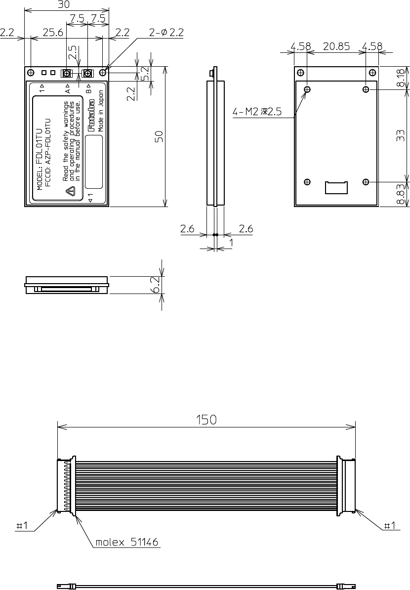
68
7.4
Dimensions
7.4.1 FDL01TU
7.4.2 Communication Cable

Futaba Corporation Rev. 020323-01
Futaba Corporation
Radio Control Equipment Group
1080 Yabutsuka Chosei
Chiba, 299-4395 JAPAN
Tel: +81 (475) 32-6173, Fax: +81(475) 32-
6179
Internet: www.futaba.co.jp
In the United States
Futaba Corporation of America
Industrial Radio Control Department
1605 Penny Lane
Schaumburg, IL 60173
Tel: (847) 884-1444, Fax: (847) 884-1635
Internet: www.futaba.com
In the Europe
Pending.