Futaba FP-PK-FM-75 3 Channel Radio Control Transmitter User Manual Revised Users Manual Part 1
Futaba Corporation 3 Channel Radio Control Transmitter Revised Users Manual Part 1
Futaba >
Contents
- 1. Revised Users Manual Part 1
- 2. Revised Users Manual Part 2
Revised Users Manual Part 1
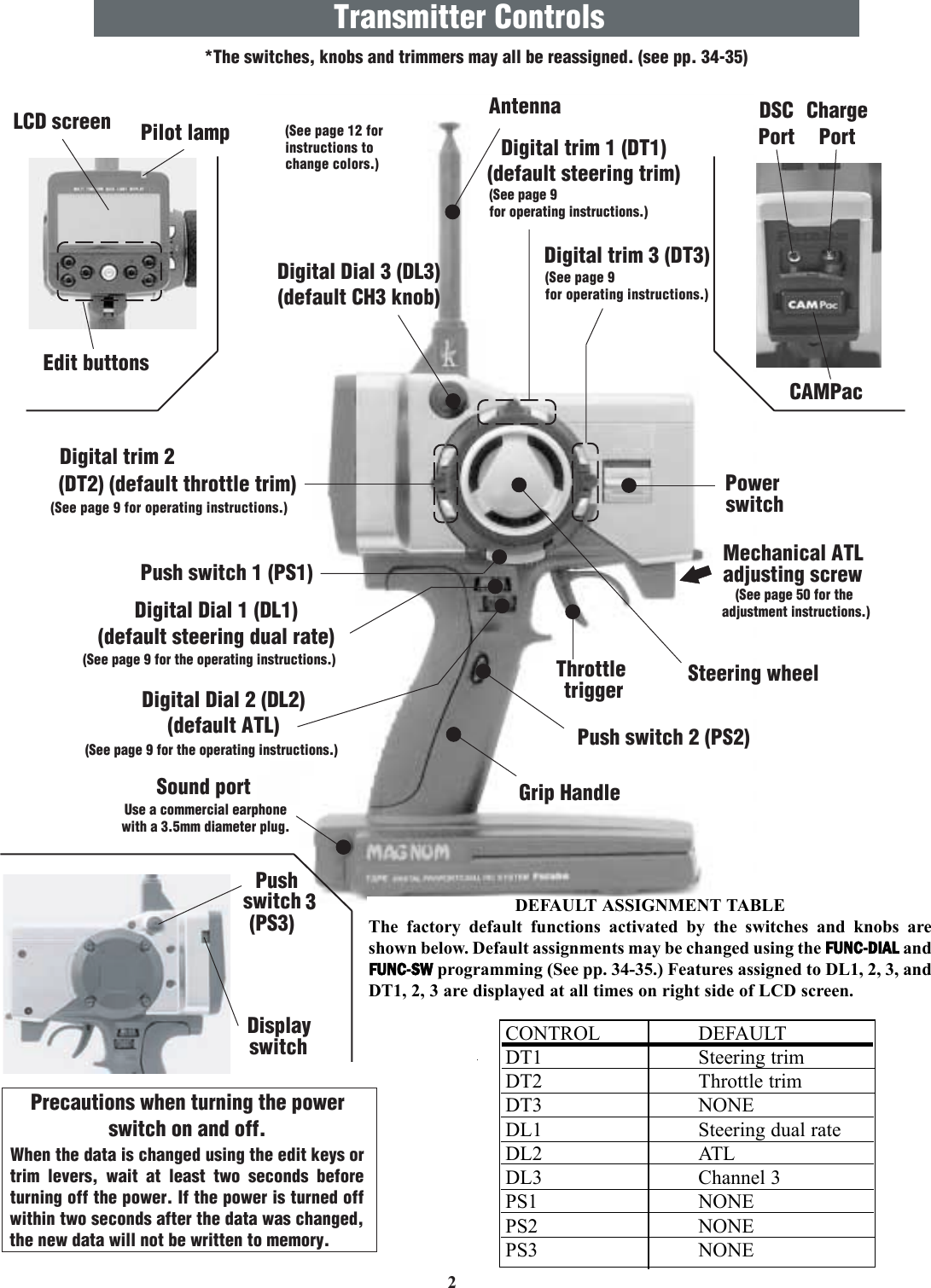
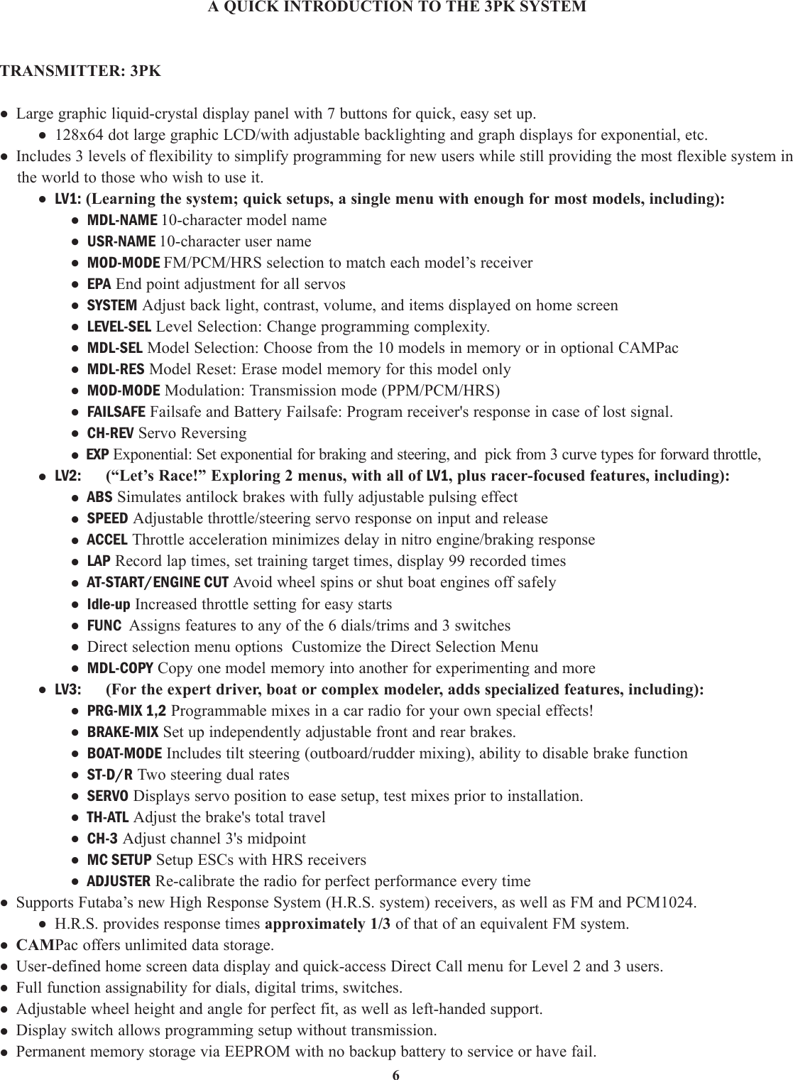
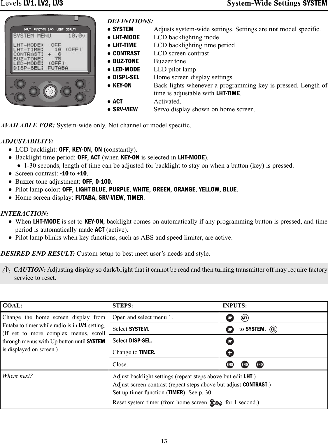
![5•Transmitter, including RF module* (PK) and NiCdbattery pack NT8F700B (FUTM1462)•Receiver (R113iP or R203HRF)•110V wall charger FBC19B (USA)•Frequency Flag/Number set•Wheel position offset adapter (APA)Transmitter T3PK (Pistol, 3 channels)Operating system: FM/PCM1024/HRSTransmitting frequency: 27, 75 MHz bands* Modulation: FM/PPM, HRS-FM or PCM1024, switchablePower supply: 9.6V NT8F700B NiCd batteryCurrent drain: 250 mA or lessReceiver R113iP ( PCM Single conversion, 3 channels)Receiving frequency: 27, 75 MHz bands *‡Intermediate freq.: 455 kHzPower requirement: 4.8V or 6.0V NiCd battery or 4.8V (4 cells) alkalineCurrent drain: 18 mASize: 1.69" x 1.13" x 0.63" [42.7 x 28.7 x 16.0mm]Weight: 0.74oz [21g]Receiver R203HF (3 channels, HRS single conversion)Receiving frequency: 27, 75 MHz bands *‡Intermediate frequency: 455kHzPower requirement: 6.0V only (shared with servos)Current drain: 14mASize: 1" x 1-1/2" x 9/16" [25.6 x 37.7 x 14.3mm] Weight: .6oz [17g]Always use only: “HRS” mode on transmitter6V Digital Servo, including throttle6V NiCd battery* Transmitter band may only be changed by changing themodule. Receiver band cannot be changed. Band cannot bechanged by simply changing crystals.‡ Only 27, 75MHz bands are legal for R/C ground usein the North America.Other bands are sold and used in other countries only.CONTENTS AND TECHNICAL SPECIFICATIONS(Specifications and ratings are subject to change without notice.)Your system includes the following components:The following additional accessories are available from your dealer. Refer to a Futaba catalog for more information:•CAMPac Memory module — the optional DP-16K CAMPac increases your model storage capability (to 20 modelsfrom 10) and allows you to transfer programs to another 3PK transmitter. Note that data may not be transferred to/fromany other model of transmitter (3PJ, etc). CAUTION - Insertion of a CAMPac containing data of a different transmitter type (ex: 3PJ) will result ina complete CAMPac data reset and loss of all data.•Transmitter battery pack — the NT8F700B (700mAh) transmitter NiCd battery pack may be easily exchanged with afresh one to provide enough capacity for extended sessions.•Y-harnesses, servo extensions, etc – Genuine Futaba extensions and y-harnesses, including a Heavy-Duty version withheavier gauge wire, are available to aid in your larger model and other installations.•5-cell (6.0V) receiver battery packs. All Futaba equipment (except that which is specifically labeled otherwise) isdesigned to work with 4.8V (NiCd 4 cells) or 6.0V (NiCd 5 cells or alkaline 4 cells). Using a 6.0V pack increases thecurrent flow to the servos, which accelerates their rate of response and their torque. However, because of this fastercurrent draw, a 5-cell battery pack of the same mAh rating will last approximately ¾ the time of a 4-cell pack. CAUTION - NOTE that HRS receivers require 6.0 volts and will not operate with 4.8V 4-cell packs.•Gyros – a variety of genuine Futaba gyros are available for your specialized model needs. •FailSafe: the FS1 FailSafe may be used with standard PPM/FM receivers to return throttle to idle in case of a loss of signal,similar to the FailSafe function of PCM/HRS receivers. NOTE that HRS receivers can not operate with the FS1.•Battery Holder (Transmitter): This battery holder is necessary when using the transmitter with dry cell batteries. For adescription of how to install the battery holder to the transmitter, see “NiCd Replacement” on page 54.•DSC cord – allows setup and testing without transmitting. Requires DSC compatible receiver and DSC cord. With transmitterand receiver off, plug cord into transmitter and then into receiver battery slot. Turn on receiver power. All programming andsetup may be done in this matter without transmitting. See glossary for a list of DSC-compatible receivers.](https://usermanual.wiki/Futaba/FP-PK-FM-75.Revised-Users-Manual-Part-1/User-Guide-284302-Page-5.png)
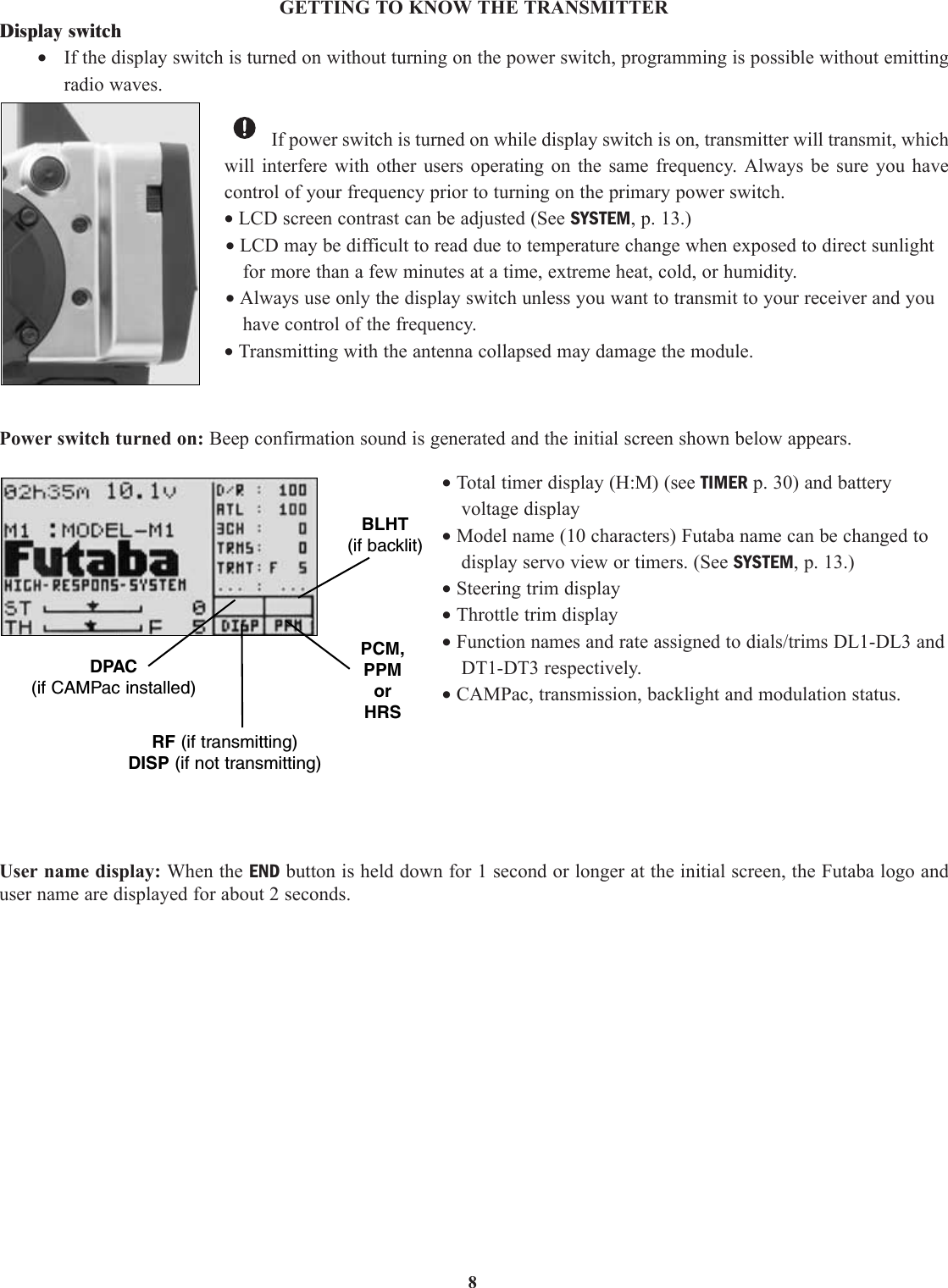
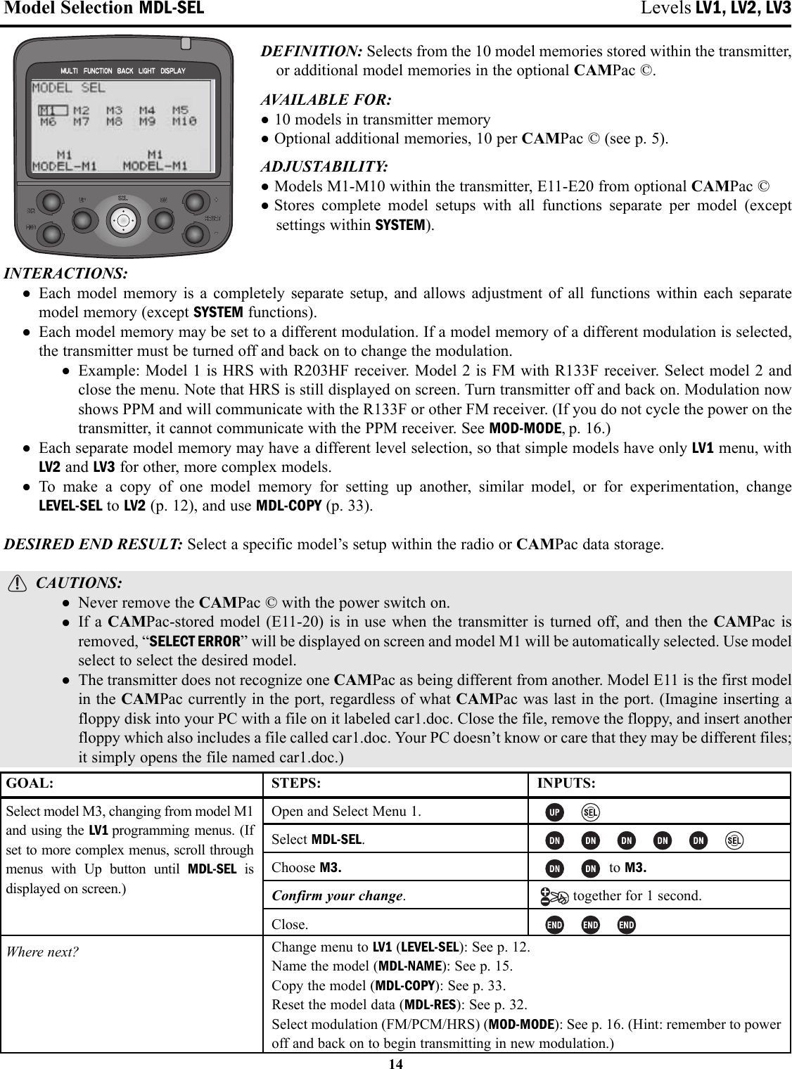
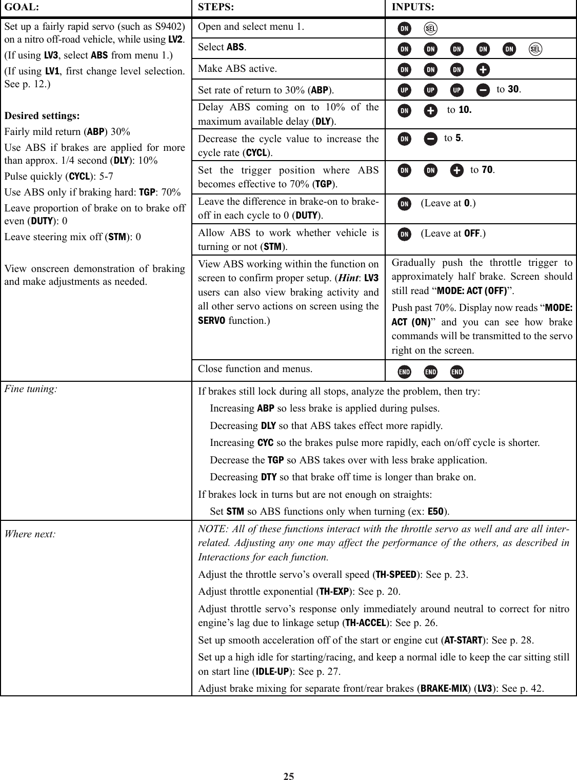
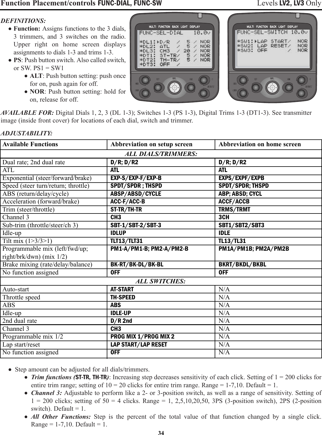
![Anti-Lock Braking ABS Levels LV2, LV3 OnlyDEFINITIONS: • ABS: Simulates a full size car’s antilock braking by pulsing the brake on and off rapidly.• ABP: Amount of brake return, how far the braking response is decreasedduring the pulses.• DLY: Delay; determines how long the braking is applied before ABS begins to operate.• CYC: Cycle speed adjustment, sets how rapidly the brakes cycle from fullbrake to ABP and back.• TGP: Trigger point, sets at what point ABS will be activated. ABS does notrespond if less brake is provided than the trigger point setting.• DTY: Cycle duty ratio, sets the proportion of the total cycle spent with brakesapplied full vs. ABP.• STM: Steering mix setup, controls when the ABS is triggered based upon amount of steering input. Designed todecrease skidding when vehicle is in a turn, and minimize spin outs.AVAILABLE FOR: Braking only.ADJUSTABILITY: • ABP: 0 (no ABS) to 100% [Servo goes to neutral (no brake) during pulse].• DLY: 0 (ABS responds immediately) to 100% (1.7 seconds of full brake before ABS takes over).• CYC: 1 (fastest) to 30 (slowest). Default=10.• TGP: 10-100.• DTY: -3 (longest full brake application — most likely to skid) to + 3 (shortest full brake – least likely to skid).• STM: OFF, N10-N100, E10-E100.• MODE:Inhibited, Active but switch is off, Active and switch is on.• Switch assignment can be changed in FUNC-SW (see pp. 34-35).• Each ABS variable can be assigned to dials in FUNC-DIAL (pp. 34-35) for on-the-course adjustability.INTERACTIONS:• EPA, servo reversing, dual rates, Speed Limiter, acceleration, auto-start, and exponential all interact to create theoverall braking effect.• Brake mixing works with ABS as if only one brake servo were used. No second setup for ABS is required.• Trigger point, steering mix and assigned switch each control ABS. All three must “say OK” for ABS to respond.DESIRED END RESULT: Model stops as rapidly as possible without skidding.CAUTIONS:• Careful analysis of the problem causing skids is required to adjust the proper portion of ABS for best results.• Adjustments to EPA, auto-start, expo, speed, brake mixing, vehicle’s suspension, tire compounds, enginetuning and ATL will all affect the performance of the ABS settings.24](https://usermanual.wiki/Futaba/FP-PK-FM-75.Revised-Users-Manual-Part-1/User-Guide-284302-Page-24.png)