Futaba FP-PK-FM-75 3 Channel Radio Control Transmitter User Manual Revised Users Manual Part 2
Futaba Corporation 3 Channel Radio Control Transmitter Revised Users Manual Part 2
Futaba >
Contents
- 1. Revised Users Manual Part 1
- 2. Revised Users Manual Part 2
Revised Users Manual Part 2
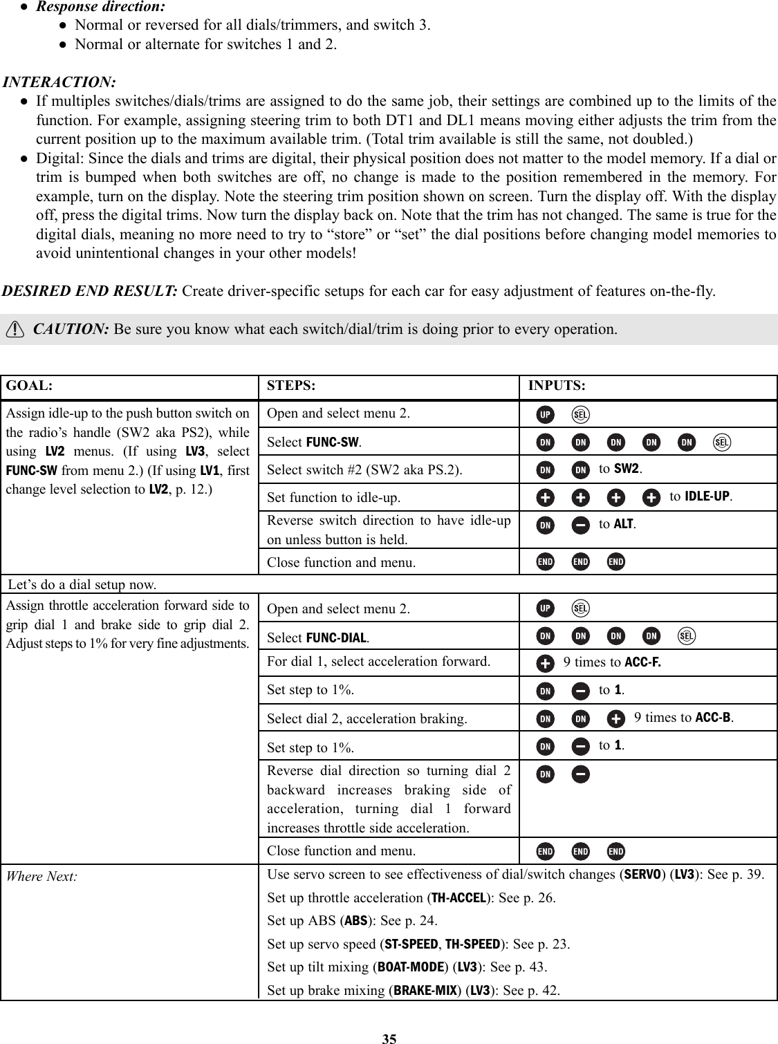
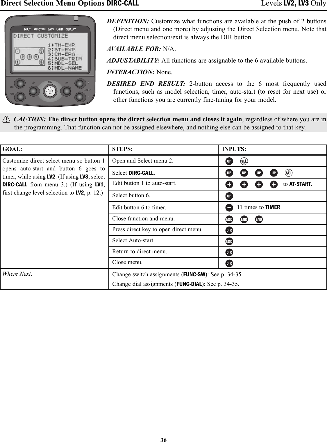

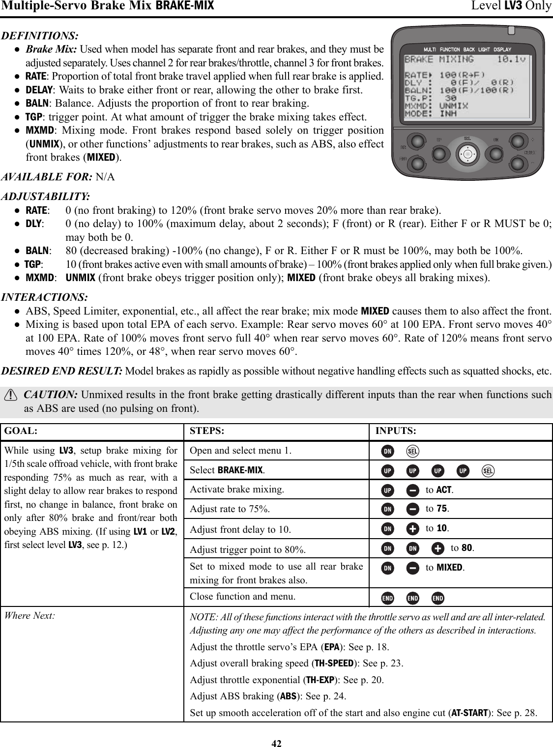
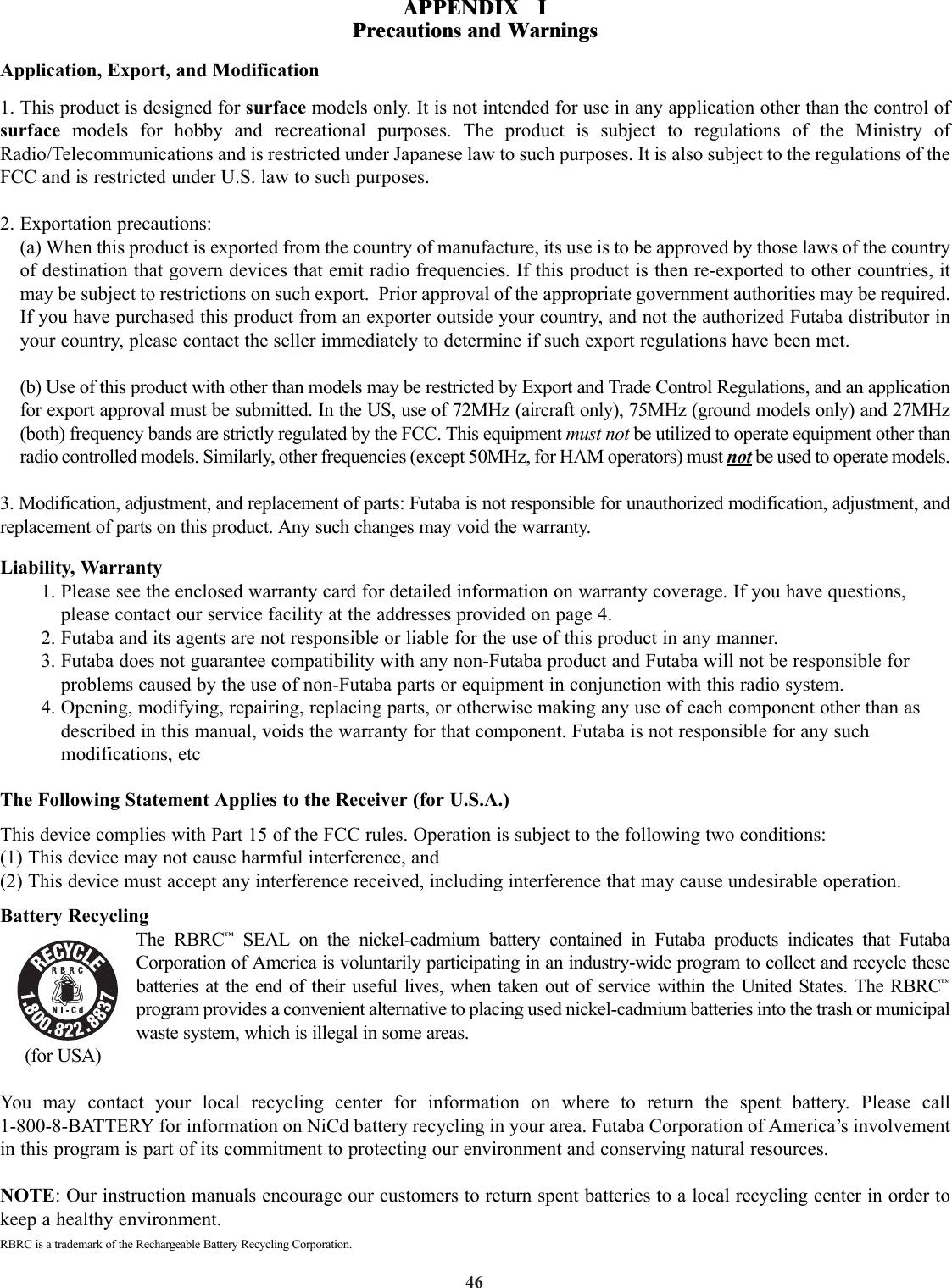
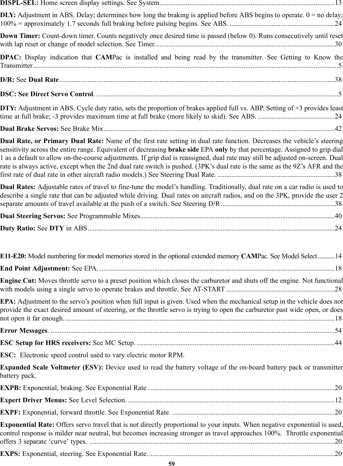
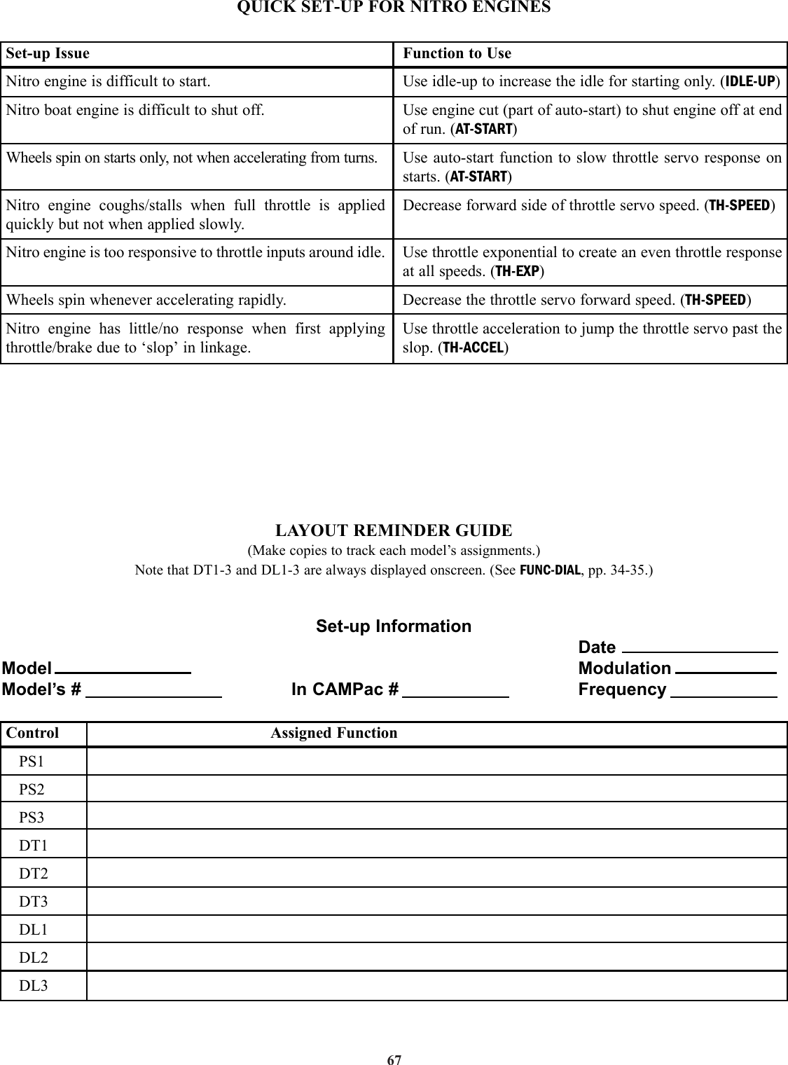
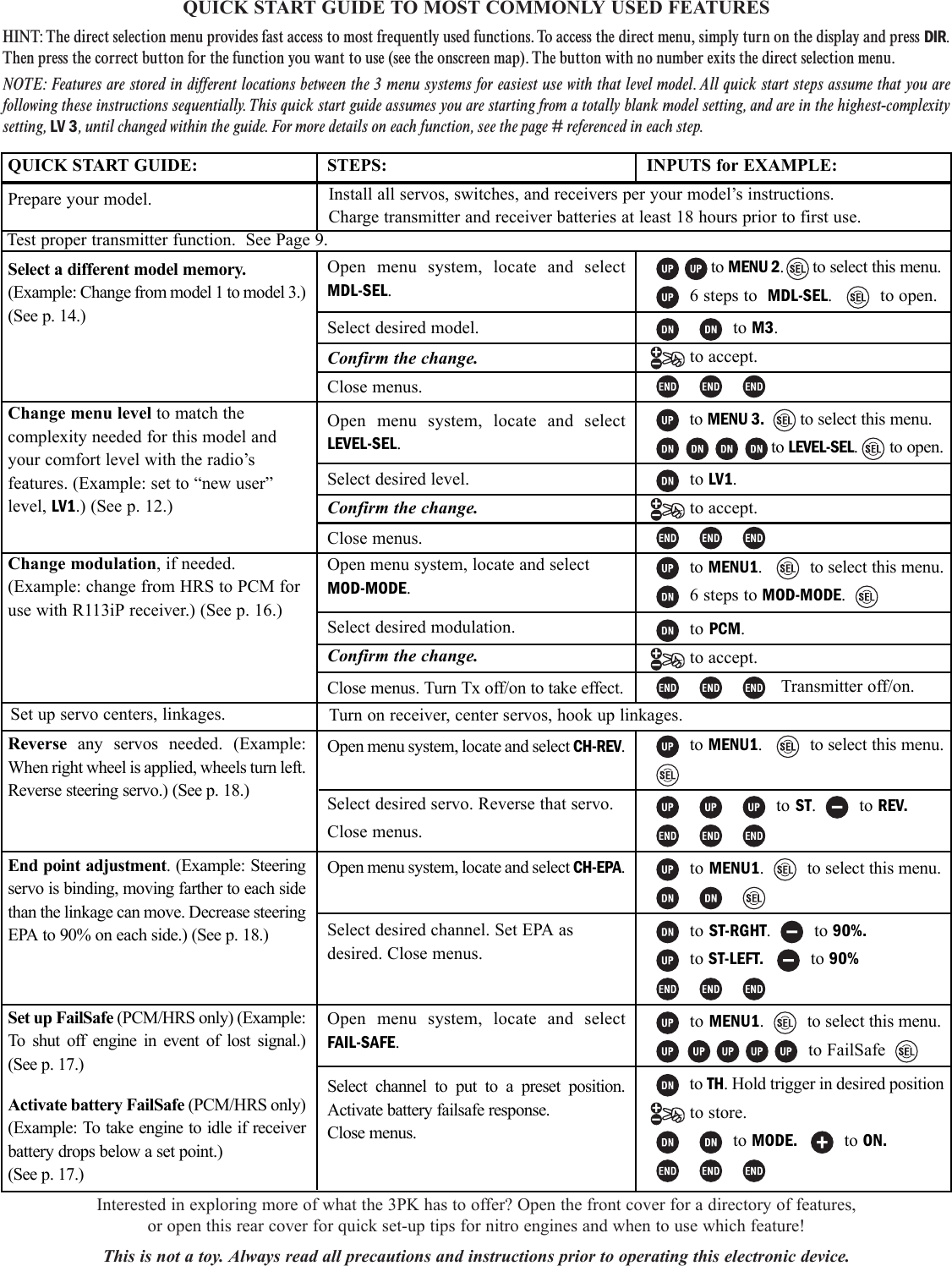
![ADJUSTABILITY: • Master: Throttle, steering, channel 3.• Slave: Throttle, steering, channel 3.• A and B adjustments [Up/forward/left and down/brake/right (for ch3/throttle/steering respectively)]: -100% (moveexact opposite of master) to 0 (no movement of slave) to +100% (move exactly same as master). Default: 50%.Adjustable while in use by selecting a dial/trim for programmable mix adjustments A and B in FUNC-DIAL, pp. 34-35.• Offset: -100% to 0 to +100%. Default: 0%.• Master mixed mode: Off, mixed. Default: off.• Trim: Off, On. Default: Off.• Switch: An on/off switch may be assigned for each mix in FUNC-SW (see pp. 34-35).INTERACTION: EPA affects total travel available to both servos. Master mixed mode “mixed” means that all otherfunctions affecting the primary channel also affect the secondary channel.DESIRED END RESULT: Varies based upon user setup.CAUTION: Be sure to test all mixes at every step to ensure no unexpected difficulties occur.41GOAL:Set up a programmable mix from steeringto lights so that headlights turn withsteering wheel, while using LV3. (If usingLV1 or LV2, first select level LV3, see p. 12.)STEPS:Select programmable mix 1.Make mix active.Set master channel as steering.Set slave channel as ch 3.Set left and right travel as 100%.Set master mixed mode to mixed so othermixes affecting throttle position alsoaffect headlight angle.Set trim on so movement of steering trimalso moves headlights.Close function and menu.INPUTS:to ACT.(already steering)to CH3.to 100%. to 100%.to MIX.to ON.GOAL:Use mixes to increase steering travel slightlywhen dual rate and EPA are not enough,while using LV3. [Note that anything morethan 10% (or less if subtrim is >0) will notmove the servo any further, as the servo’smaximum mechanical travel is exceeded. Besure to check actual travels, including subtrims, by testing servo operation.] (If usingLV1 or LV2, first select level LV3, see p. 12.)Where Next:STEPS:Select programmable mix 1.Make mix active.Set master channel as steering.Set slave channel as steering.Set left and right travel as 10%.Leave offset at 0 and trim off.Set master mixed mode to mixed so othermixes affecting steering also. See theincrease.Close function and menu.INPUTS:to ACT.(already steering)to ST.to 10%.to 10%.to MIX.Programmable mix to set up differential steering (similar to the brake mixing programbut for 4-wheel steering or for 2-wheel steering using 2 servos and creating adjustableacumen): see www.futabarc.com\faq\faq-3pk.htmlAdjust steering EPA (ST-EPA): See p. 18.Adjust steering dual rate (ST-DR): See p. 38.Adjust steering subtrim (SUB-TRIM): See p. 22.](https://usermanual.wiki/Futaba/FP-PK-FM-75.Revised-Users-Manual-Part-2/User-Guide-284303-Page-7.png)