Futaba FP-PK-FM-75 3 Channel Radio Control Transmitter User Manual Revised Users Manual Part 2
Futaba Corporation 3 Channel Radio Control Transmitter Revised Users Manual Part 2
Futaba >
Contents
- 1. Revised Users Manual Part 1
- 2. Revised Users Manual Part 2
Revised Users Manual Part 2
• Response direction:
• Normal or reversed for all dials/trimmers, and switch 3.
• Normal or alternate for switches 1 and 2.
INTERACTION:
• If multiples switches/dials/trims are assigned to do the same job, their settings are combined up to the limits of the
function. For example, assigning steering trim to both DT1 and DL1 means moving either adjusts the trim from the
current position up to the maximum available trim. (Total trim available is still the same, not doubled.)
• Digital: Since the dials and trims are digital, their physical position does not matter to the model memory. If a dial or
trim is bumped when both switches are off, no change is made to the position remembered in the memory. For
example, turn on the display. Note the steering trim position shown on screen. Turn the display off. With the display
off, press the digital trims. Now turn the display back on. Note that the trim has not changed. The same is true for the
digital dials, meaning no more need to try to “store” or “set” the dial positions before changing model memories to
avoid unintentional changes in your other models!
DESIRED END RESULT: Create driver-specific setups for each car for easy adjustment of features on-the-fly.
CAUTION: Be sure you know what each switch/dial/trim is doing prior to every operation.
35
GOAL:
Assign idle-up to the push button switch on
the radio’s handle (SW2 aka PS2), while
using LV2 menus. (If using LV3, select
FUNC-SW from menu 2.) (If using LV1, first
change level selection to LV2, p. 12.)
Assign throttle acceleration forward side to
grip dial 1 and brake side to grip dial 2.
Adjust steps to 1% for very fine adjustments.
Where Next:
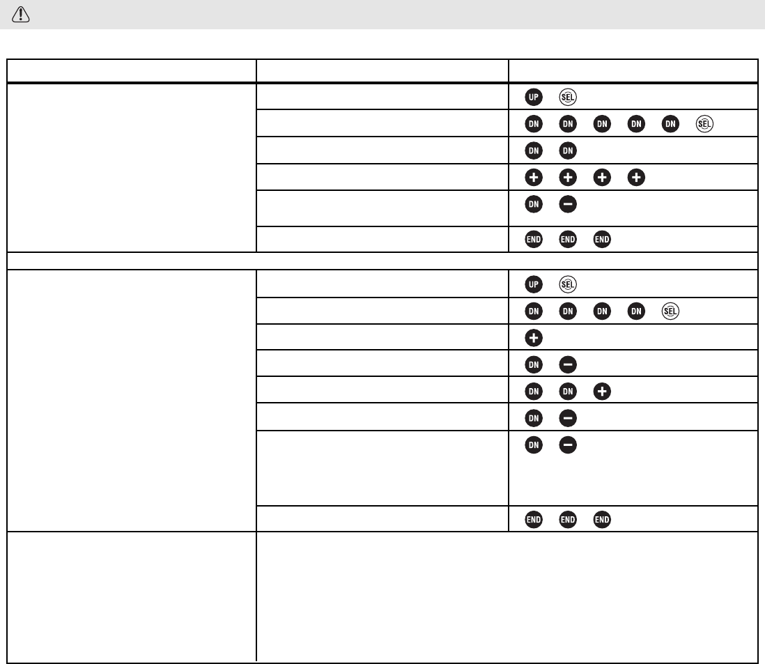
STEPS:
Open and select menu 2.
Select FUNC-SW.
Select switch #2 (SW2 aka PS.2).
Set function to idle-up.
Reverse switch direction to have idle-up
on unless button is held.
Close function and menu.
Open and select menu 2.
Select FUNC-DIAL.
For dial 1, select acceleration forward.
Set step to 1%.
Select dial 2, acceleration braking.
Set step to 1%.
Reverse dial direction so turning dial 2
backward increases braking side of
acceleration, turning dial 1 forward
increases throttle side acceleration.
Close function and menu.
INPUTS:
to SW2.
to IDLE-UP.
to ALT.
9 times to ACC-F.
to 1.
9 times to ACC-B.
to 1.
Use servo screen to see effectiveness of dial/switch changes (SERVO) (LV3): See p. 39.
Set up throttle acceleration (TH-ACCEL): See p. 26.
Set up ABS (ABS): See p. 24.
Set up servo speed (ST-SPEED, TH-SPEED): See p. 23.
Set up tilt mixing (BOAT-MODE) (LV3): See p. 43.
Set up brake mixing (BRAKE-MIX) (LV3): See p. 42.
Let’s do a dial setup now.
36
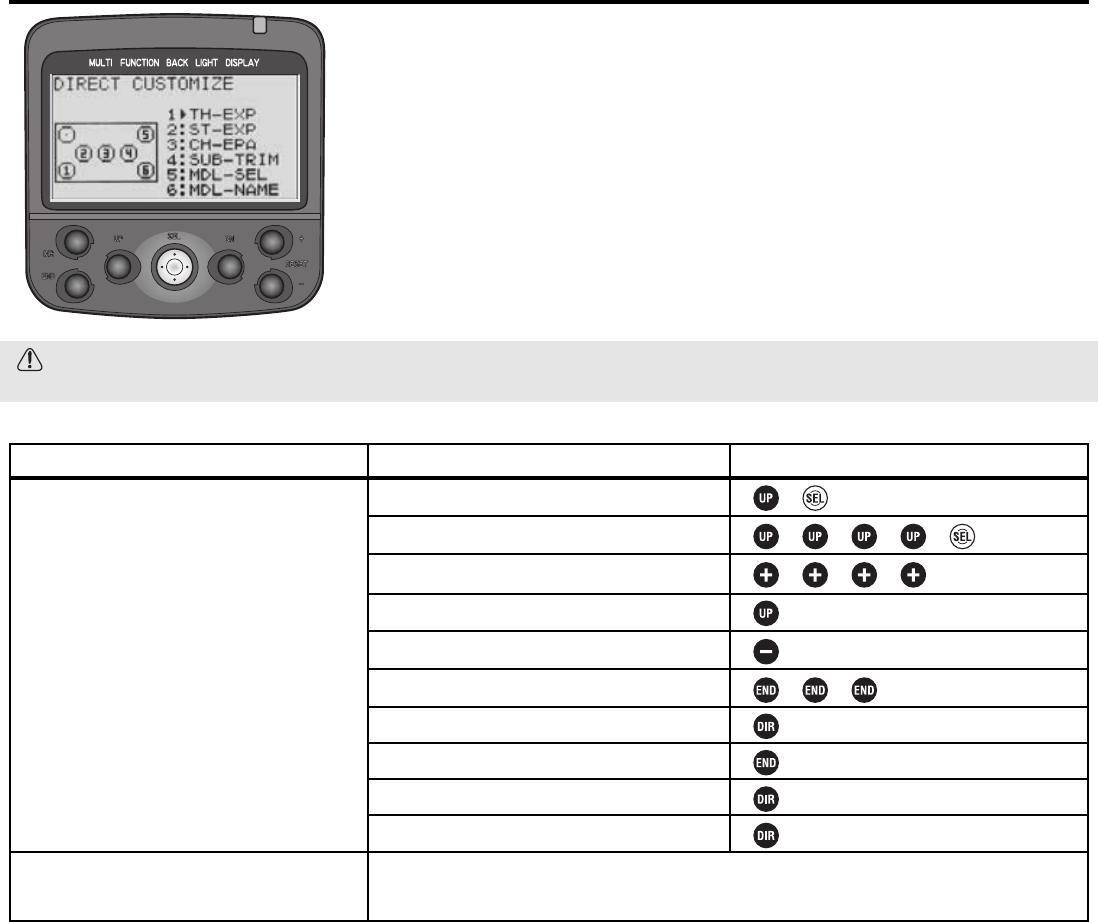
Direct Selection Menu Options DIRC-CALL Levels LV2, LV3 Only
DEFINITION: Customize what functions are available at the push of 2 buttons
(Direct menu and one more) by adjusting the Direct Selection menu. Note that
direct menu selection/exit is always the DIR button.
AVAILABLE FOR: N/A.
ADJUSTABILITY: All functions are assignable to the 6 available buttons.
INTERACTION: None.
DESIRED END RESULT: 2-button access to the 6 most frequently used
functions, such as model selection, timer, auto-start (to reset for next use) or
other functions you are currently fine-tuning for your model.
CAUTION: The direct button opens the direct selection menu and closes it again, regardless of where you are in
the programming. That function can not be assigned elsewhere, and nothing else can be assigned to that key.
GOAL:
Customize direct select menu so button 1
opens auto-start and button 6 goes to
timer, while using LV2. (If using LV3, select
DIRC-CALL from menu 3.) (If using LV1,
first change level selection to LV2, p. 12.)
Where Next:
STEPS:
Open and Select menu 2.
Select DIRC-CALL.
Edit button 1 to auto-start.
Select button 6.
Edit button 6 to timer.
Close function and menu.
Press direct key to open direct menu.
Select Auto-start.
Return to direct menu.
Close menu.
INPUTS:
to AT-START.
11 times to TIMER.
Change switch assignments (FUNC-SW): See p. 34-35.
Change dial assignments (FUNC-DIAL): See p. 34-35.
LV3 FUNCTIONS for the Expert Driver, Boats or Complex Models
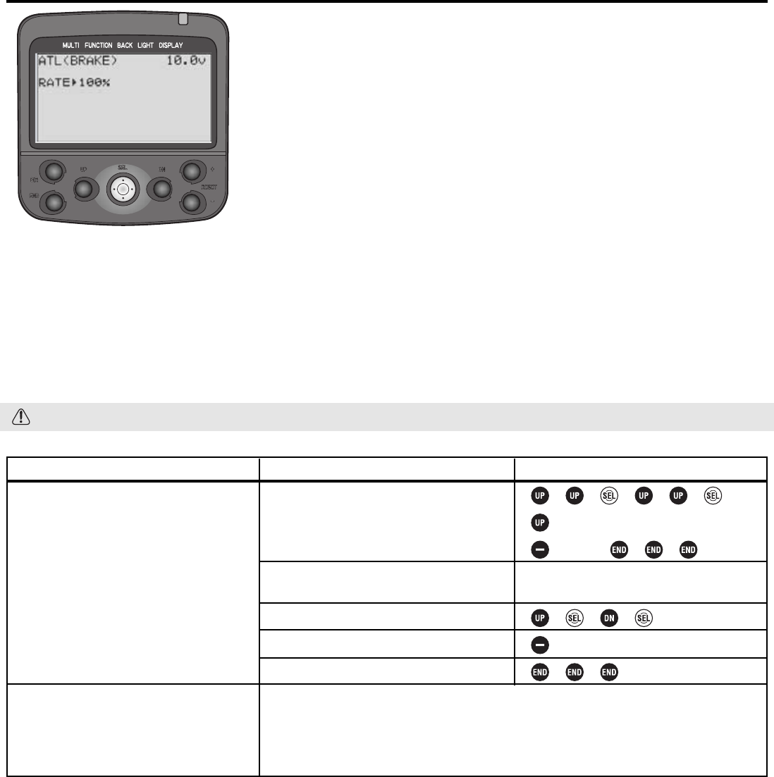
Level LV3 Only Programming Adjustment of Throttle ATL ATL
DEFINITIONS:
•ATL, electronic: (Adjustable throttle limiter) Adjusts total travel available to the
braking side of the throttle servo, similar to adjusting EPA, but allows adjustment
“on the fly” when ATL is assigned to a dial. When brake mixing is used in the
unmixed mode, this adjusts the rear brake servo without changing amount of braking
to front brake servo.
•ATL, mechanical: Decreases the physical distance the brake trigger can move.
See p. 51.
AVAILABLE FOR: Braking only.
ADJUSTABILITY:
• RATE: 0 (no braking at all) to 100% (same as EPA). Default: 100%.
• Rate adjustment: May be easily adjusted while driving (if assigned to a dial/trim, see FUNC-DIAL, pp. 34-35). Default
assignment is to gripper dial 2.
INTERACTION: EPA affects total travel available to the servo. ATL is directly proportional to EPA.
DESIRED END RESULT: Quickly adjust overall braking sensitivity, including with a dial while driving on the track.
CAUTION: Dial 2 is assigned for ATL adjustment as a default, even if user does not realize it.
37
GOAL:
While using LV3:
•Reassign the ATL adjustment to digital
trim 1;
•Adjust the ATL setting from 100% to
20% (with the digital trim centered).
(If using LV1 or LV2, first change level
selection, see p. 12.)
Where Next:
STEPS:
Use FUNC-DIAL to assign ATL to digital
trim 1.
While viewing home screen, adjust digital
trim 1 until ATL reads 0.
Select ATL.
Adjust ATL to 20%.
Close function and menu.
INPUTS:
9 steps to DT1.
to ATL.
Move trim 1, if necessary, until display
reads 0for ATL.
to 20%.
Adjust the throttle servo’s EPA (EPA):See p. 18.
Set up channel 3 control (CH3-POSI):See p. 40.
Set up brake mixing for separate front/rear brakes (BRAKE-MIX):See p. 42.
Set up tilt mixing for boats (BOAT-MODE):See p. 43.
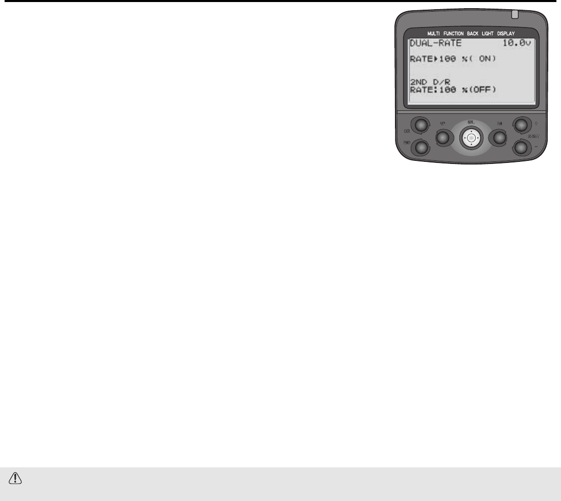
Steering Dual Rate ST-D/R Level LV3 Only
DEFINITIONS:
•Dual Rate, or primary dual rate: Decreases the vehicle’s steering sensitivity
across the entire range. Equivalent of decreasing steering EPA by that percentage.
Assigned to grip dial 1 as a default to allow on-the-course adjustments. If grip dial
is unassigned, dual rate may still be adjusted on-screen. Dual rate is always active,
except when the 2nd dual rate switch is pushed. (3PK’s dual rate is the same as the
9Z’s AFR, and the first rate of dual rate in other aircraft style radio models.)
•Second Dual Rate: A second while-driving rate of servo response, available
with the push of a switch. The 2nd dual rate is meant to be used to temporarily
have more/less servo travel available without having to readjust the dual rate
dial. Second dual rate is proportional to the EPA not the primary dual rate.
Examples: Used for getting away from walls, crashes, a single hairpin turn on an
otherwise non-technical track.
AVAILABLE FOR: Steering only.
ADJUSTABILITY:
• RATE: 0 (no steering at all) to 100% (same as EPA). Default: 100%.
• Switch assignment (to change from primary dual rate to second dual rate): Must be set using FUNC-SW, see pp. 34-
35. Default: no dual rate switch assigned; 2nd dual rate is not usable until a switch is assigned.
• Rate adjustment: Both primary rate and 2nd rate adjustments may be assigned to any dial/digital trim (see FUNC-DIAL,
pp. 34-35) to allow adjustment while driving. If no dial/trim is assigned, then adjustments are made only within the
D/R function. Defaults: D/R on dial 1, 2nd D/R not assigned.
INTERACTIONS:
• EPA affects total travel available to steering servo. Both dual rates are directly proportional to the total EPA.
• Exponential adjusts how much the servo is moved around center without having any effect on the servo travel at full
stick; dual rate uniformly decreases the servo’s movement all along the travel.
• Speed Limiter slows how quickly the servo moves to a certain point without decreasing its overall travel rather than
decreasing the servo’s movement to decrease its sensitivity.
DESIRED END RESULT: Quickly adjust steering overall sensitivity with a dial while driving on the track; have a second
travel rate available for unusual situations, such as a crash.
CAUTION: Dual rate is active as a default and is adjusted from normal setting (100%) with dial 1 unless it is
reassigned by the user.
38
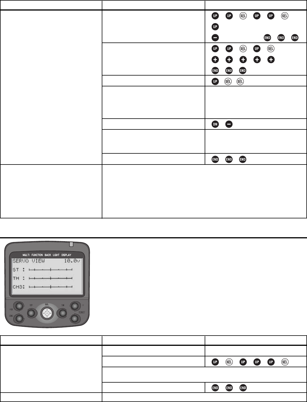
Level LV3 Only Servo View SERVO
DEFINITION: Shows the exact outputs the transmitter is sending to the servos. Allows
for easy testing/experimenting even when receiver and servos are not yet installed.
AVAILABLE FOR: throttle, steering, channel 3.
ADJUSTABILITY: N/A.
INTERACTION: Shows all servo interactions from programming.
DESIRED END RESULT: Confirm programming is having desired result before
radio gear is set up in model.
39
GOAL:
While using LV3:
•Reassign digital trim 1 to the dual rate
adjustment;
•Assign dual rate switching to switch 1;
•Adjust 2nd dual rate to slightly less than
maximum (95%) for quick steering to get
out of tight spots.
(If using LV1 or LV2, first change level
selection, see p. 12.)
Where Next:
STEPS:
Use FUNC-DIAL to assign dual rate to
digital trim 1.
Use FUNC-SW to assign dual rate switching
to switch 1.
Select dual rate.
Test the dual rate adjustment by moving
digital trim 1.
Adjust 2nd dual rate down to 95%.
Test the 2nd dual rate switch by pressing
switch 1.
Close function and menu.
INPUTS:
9 steps to DT1.
12 steps to D/R.
to D/R 2nd.
Move digital trim 1 counterclockwise; see
the rate decrease on-screen. (Note that the
rate per click can be adjusted in the
function dial screen.)
to 95.
Press switch 1 (below the wheel) and notice
2nd D/R Rate changes from OFF to ON, as
primary rate changes from ON to OFF.
Adjust the steering servo’s EPA (EPA): See p. 18.
Adjust steering channel exponential (ST-EXP): See p. 20.
Adjust steering servo response speed (ST-SPEED): See p. 23.
Set up channel 3 control (CH3): See p. 40.
Set up brake mixing for separate front/rear brakes (BRAKE-MIX): See p. 42.
Use servo screen to see exactly how dual rates are performing (SERVO): See below.
GOAL:
View screen after setting up steering dual
rate to confirm switch and dials are
working as planned, while using LV3.
(If using LV1 or LV2, first change level
selection, see p. 12.)
Where Next:
STEPS:
Set up dual rates.
Select servo display.
Close function and menu.
INPUTS:
See page 38.
Return to function and make adjustments as needed, or complete installation in model.
Holding full right turn, adjust dial to see change in total servo throw, then hold dual
rate switch, and notice change in total throw.
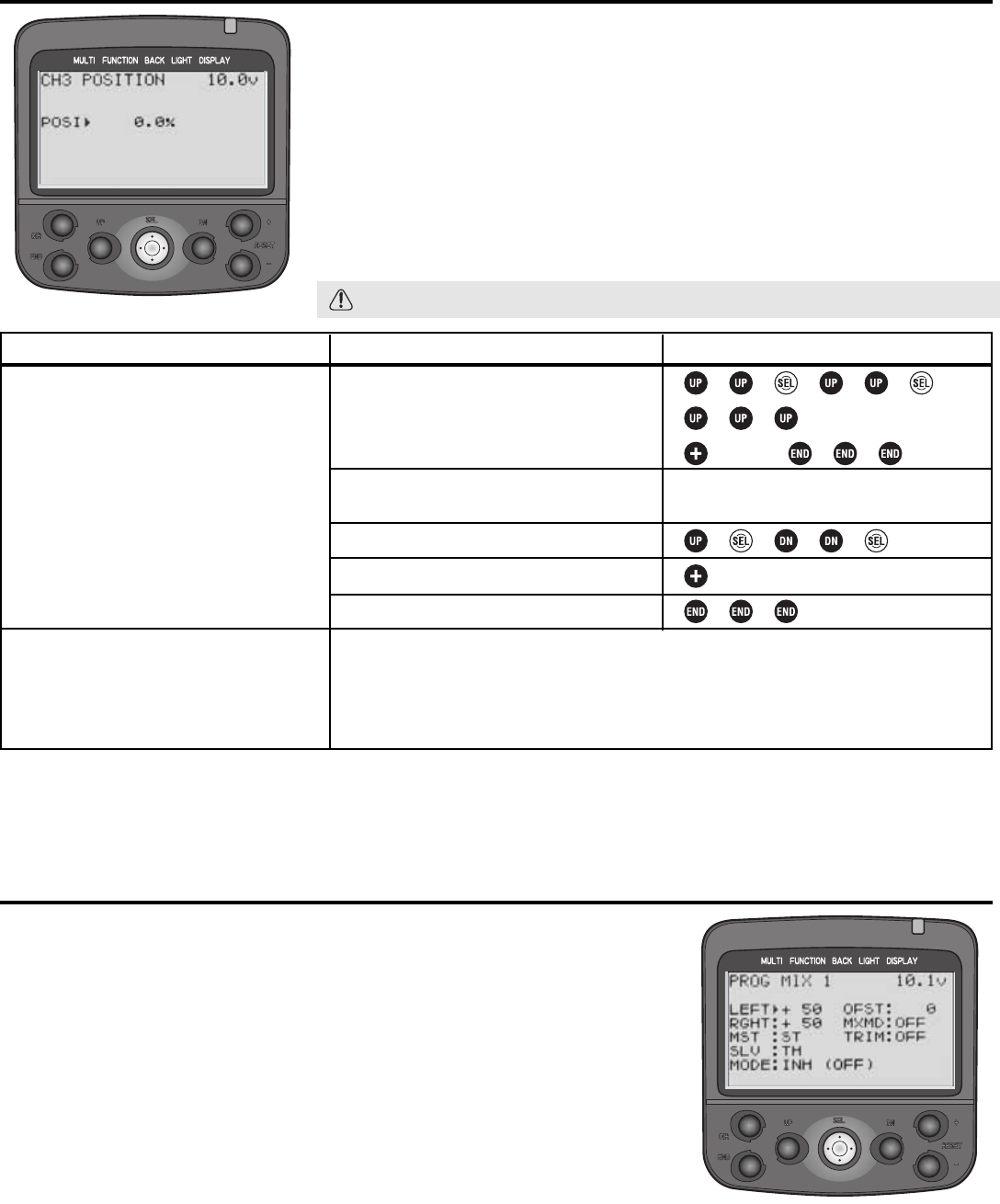
Channel 3 Control CH3-POSI Level LV3 Only
DEFINITION: Sets the default or neutral position for the channel 3 servo.
Defaults to being adjustable with dial 3.
AVAILABLE FOR: channel 3 only.
ADJUSTABILITY: -100% to 0 to +100%. Default adjusts with dial 3, may be
reassigned with FUNC-DIAL (see pp. 34-35).
INTERACTION: Channel 3 position is relative to channel 3’s EPA.
DESIRED END RESULT: Fine tune the channel 3 neutral position. May also be
used to adjust channel 3 to a specific position and leave it there if adjustability
is not assigned to a dial (see FUNC-DIAL, pp. 34-35).
CAUTION: Dial 2 defaults to ATL adjustment, even if user does not realize it.
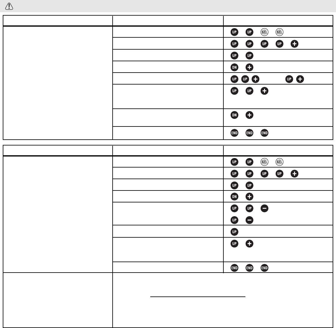
Programmable Mixes PRG-MIX1, PRG-MIX2 Level LV3 Only
DEFINITIONS:
• Programmable mixing function: Allows user to create mixing between the
steering, throttle and channel 3 servos. Brake mixing is an example of built-in mixes.
• Master: The channel the slave will follow. In brake mixing, the throttle
channel’s braking side.
• Slave: The channel that follows the master. In brake mixing, channel 3 (front brakes).
• Offset: Amount off center to adjust the mix.
• Mix Mode: Selects whether slave moves exactly based upon the master control’s
movement (unmixed) or the master channel’s servo movements after any mixing
(mixed). Brake mixing unmixed means front brakes respond exactly based upon
trigger position while rear braking is changed by ABS, Speed Limiter, etc.
• Trim: Sets whether the slave channel is (ON) or is not (OFF) adjusted with the
master when using the master channel’s trim.
AVAILABLE FOR: Throttle, steering, channel 3.
40
GOAL:
While using LV3:
•Reassign the channel 3 adjustment to
digital trim 3;
•Adjust the channel 3 “center” position from
0 to 18% (with the digital trim centered).
(If using LV1 or LV2, first select level LV3,
see p. 12.)
Where Next:
STEPS:
Use FUNC-DIAL to assign CH3 to digital
trim 3.
While viewing home screen, adjust digital
trim 3 until 3CH reads 0.
Select channel 3 positioning.
Adjust channel 3 position to 18%.
Close function and menu.
INPUTS:
to DT3.
to CH3.
Move trim 3, if necessary, until display
reads 0for 3CH.
to 18.0%.
Adjust channel 3 servo’s EPA (EPA): See p. 18.
Set up brake mixing to use channel 3 for separate front/rear brakes (BRAKE-MIX): See p. 42.
Set up tilt mixing to use channel 3 for boats (BOAT-MODE): See p. 43.
Set up programmable mixes to use channel 3 (PRG-MIX1,2): See below.
ADJUSTABILITY:
• Master: Throttle, steering, channel 3.
• Slave: Throttle, steering, channel 3.
• A and B adjustments [Up/forward/left and down/brake/right (for ch3/throttle/steering respectively)]: -100% (move
exact opposite of master) to 0 (no movement of slave) to +100% (move exactly same as master). Default: 50%.
Adjustable while in use by selecting a dial/trim for programmable mix adjustments A and B in FUNC-DIAL, pp. 34-35.
• Offset: -100% to 0 to +100%. Default: 0%.
• Master mixed mode: Off, mixed. Default: off.
• Trim: Off, On. Default: Off.
• Switch: An on/off switch may be assigned for each mix in FUNC-SW (see pp. 34-35).
INTERACTION: EPA affects total travel available to both servos. Master mixed mode “mixed” means that all other
functions affecting the primary channel also affect the secondary channel.
DESIRED END RESULT: Varies based upon user setup.
CAUTION: Be sure to test all mixes at every step to ensure no unexpected difficulties occur.
41
GOAL:
Set up a programmable mix from steering
to lights so that headlights turn with
steering wheel, while using LV3. (If using
LV1 or LV2, first select level LV3, see p. 12.)
STEPS:
Select programmable mix 1.
Make mix active.
Set master channel as steering.
Set slave channel as ch 3.
Set left and right travel as 100%.
Set master mixed mode to mixed so other
mixes affecting throttle position also
affect headlight angle.
Set trim on so movement of steering trim
also moves headlights.
Close function and menu.
INPUTS:
to ACT.
(already steering)
to CH3.
to 100%. to 100%.
to MIX.
to ON.
GOAL:
Use mixes to increase steering travel slightly
when dual rate and EPA are not enough,
while using LV3. [Note that anything more
than 10% (or less if subtrim is >0) will not
move the servo any further, as the servo’s
maximum mechanical travel is exceeded. Be
sure to check actual travels, including sub
trims, by testing servo operation.] (If using
LV1 or LV2, first select level LV3, see p. 12.)
Where Next:
STEPS:
Select programmable mix 1.
Make mix active.
Set master channel as steering.
Set slave channel as steering.
Set left and right travel as 10%.
Leave offset at 0 and trim off.
Set master mixed mode to mixed so other
mixes affecting steering also. See the
increase.
Close function and menu.
INPUTS:
to ACT.
(already steering)
to ST.
to 10%.
to 10%.
to MIX.
Programmable mix to set up differential steering (similar to the brake mixing program
but for 4-wheel steering or for 2-wheel steering using 2 servos and creating adjustable
acumen): see www.futabarc.com\faq\faq-3pk.html
Adjust steering EPA (ST-EPA): See p. 18.
Adjust steering dual rate (ST-DR): See p. 38.
Adjust steering subtrim (SUB-TRIM): See p. 22.
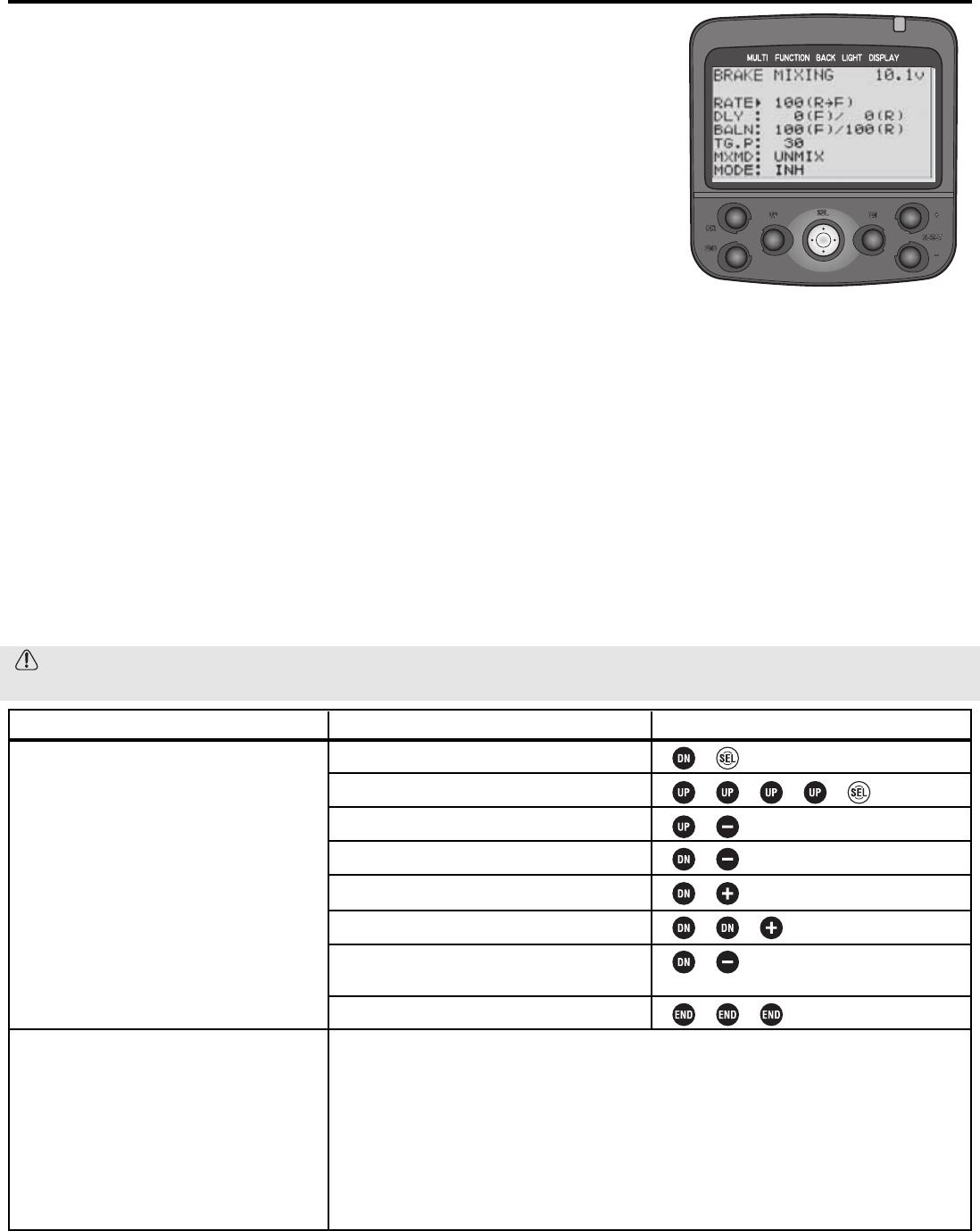
Multiple-Servo Brake Mix BRAKE-MIX Level LV3 Only
DEFINITIONS:
• Brake Mix: Used when model has separate front and rear brakes, and they must be
adjusted separately. Uses channel 2 for rear brakes/throttle, channel 3 for front brakes.
• RATE: Proportion of total front brake travel applied when full rear brake is applied.
• DELAY: Waits to brake either front or rear, allowing the other to brake first.
• BALN: Balance. Adjusts the proportion of front to rear braking.
• TGP: trigger point. At what amount of trigger the brake mixing takes effect.
• MXMD: Mixing mode. Front brakes respond based solely on trigger position
(UNMIX), or other functions’ adjustments to rear brakes, such as ABS, also effect
front brakes (MIXED).
AVAILABLE FOR: N/A
ADJUSTABILITY:
• RATE: 0 (no front braking) to 120% (front brake servo moves 20% more than rear brake).
• DLY: 0 (no delay) to 100% (maximum delay, about 2 seconds); F (front) or R (rear). Either F or R MUST be 0;
may both be 0.
• BALN: 80 (decreased braking) -100% (no change), F or R. Either F or R must be 100%, may both be 100%.
• TGP: 10 (front brakes active even with small amounts of brake) – 100% (front brakes applied only when full brake given.)
• MXMD:UNMIX (front brake obeys trigger position only); MIXED (front brake obeys all braking mixes).
INTERACTIONS:
• ABS, Speed Limiter, exponential, etc., all affect the rear brake; mix mode MIXED causes them to also affect the front.
• Mixing is based upon total EPA of each servo. Example: Rear servo moves 60° at 100 EPA. Front servo moves 40°
at 100 EPA. Rate of 100% moves front servo full 40° when rear servo moves 60°. Rate of 120% means front servo
moves 40° times 120%, or 48°, when rear servo moves 60°.
DESIRED END RESULT: Model brakes as rapidly as possible without negative handling effects such as squatted shocks, etc.
CAUTION: Unmixed results in the front brake getting drastically different inputs than the rear when functions such
as ABS are used (no pulsing on front).
42
GOAL:
While using LV3, setup brake mixing for
1/5th scale offroad vehicle, with front brake
responding 75% as much as rear, with a
slight delay to allow rear brakes to respond
first, no change in balance, front brake on
only after 80% brake and front/rear both
obeying ABS mixing. (If using LV1 or LV2,
first select level LV3, see p. 12.)
Where Next:
STEPS:
Open and select menu 1.
Select BRAKE-MIX.
Activate brake mixing.
Adjust rate to 75%.
Adjust front delay to 10.
Adjust trigger point to 80%.
Set to mixed mode to use all rear brake
mixing for front brakes also.
Close function and menu.
INPUTS:
to ACT.
to 75.
to 10.
to 80.
to MIXED.
NOTE: All of these functions interact with the throttle servo as well and are all inter-related.
Adjusting any one may affect the performance of the others as described in interactions.
Adjust the throttle servo’s EPA (EPA): See p. 18.
Adjust overall braking speed (TH-SPEED): See p. 23.
Adjust throttle exponential (TH-EXP): See p. 20.
Adjust ABS braking (ABS): See p. 24.
Set up smooth acceleration off of the start and also engine cut (AT-START): See p. 28.
43
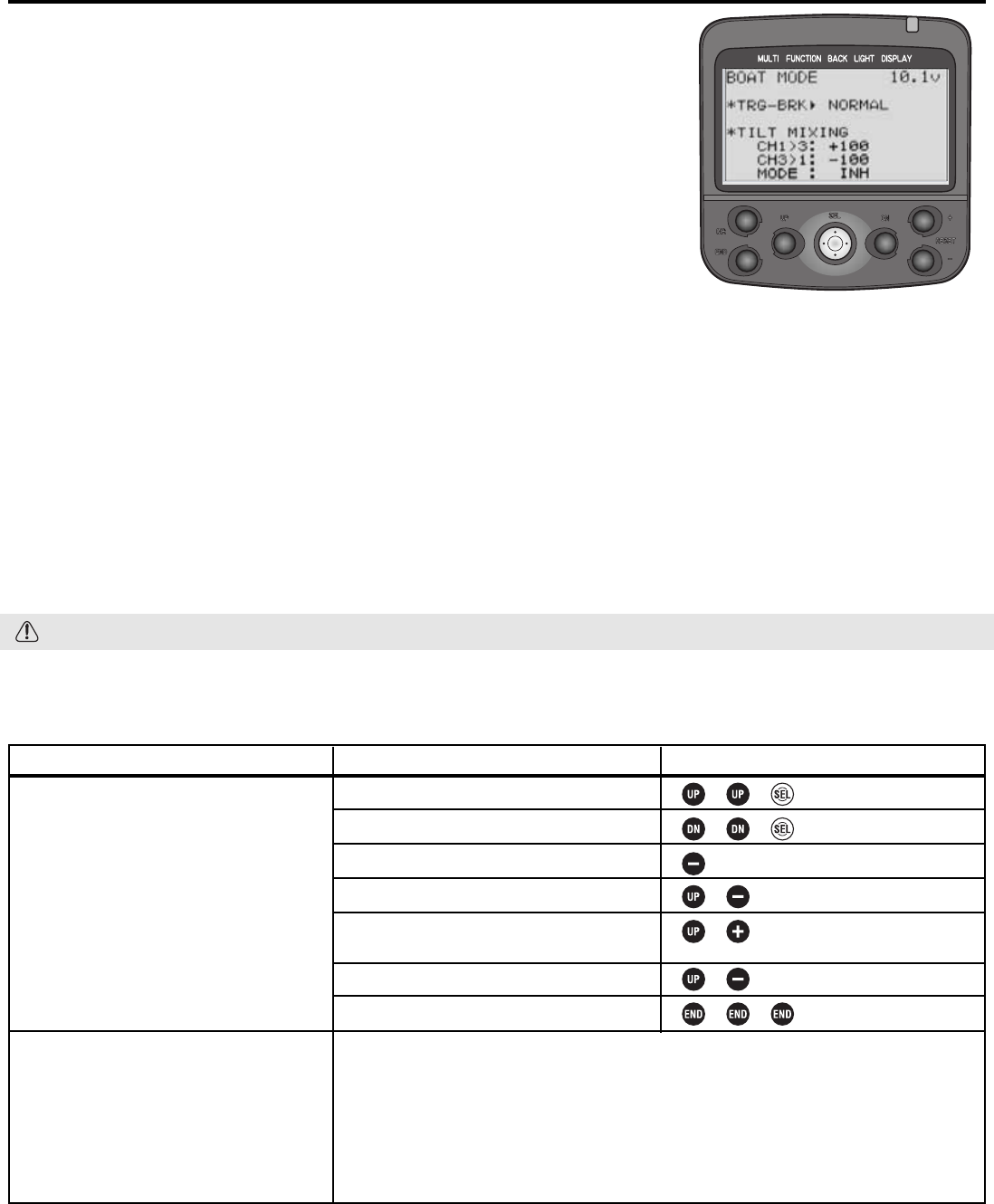
Level LV3 Only Boat Mode BOAT-MODE
DEFINITIONS:
• Boat mode: Set ups to fit specific needs of boat models rather than cars.
• TRG-BRK: Trigger-Brake operation. Shuts off brake side of servo movement for
boats without braking/reverse.
• Tilt Mixing: adjusts outboard engine positioning with rudder inputs, and adjusts
rudder with outboard engine adjustments.
• Channel 1 > 3: mix from steering (rudder) to outboard. Utilized when the
boat drops too much (or too little) into the water when giving rudder input.
• Channel 3 > 1: mixing from outboard to steering (rudder). Utilized
when the torque of the engine has more effect as the boat’s position
changes in the water, causing the boat to yaw left under acceleration.
AVAILABLE FOR: N/A
ADJUSTABILITY:
• TRG-BRK: Normal (brake operates); cut-off (no brake/reverse operation).
• CH 1>3 and CH 3>1: -100% (moves exactly opposite) to 0 (no mix) to +100% (moves exactly the same as master.)
INTERACTIONS:
• EPA, steering expo, speed, dual rate, etc., all affect the 3rd channel (master mixing is on and can not be set to off.)
• Reversing the channel 1 servo does NOT reverse the channel 3 servo.
DESIRED END RESULT: Keep outboard-powered boat up on its step and traveling straight at high speeds/rapid
acceleration, and adjust the boat’s angle in the water for ideal turning with minimum drag.
CAUTION: Remember, EPA of channel 1 affects channel 3, so check for binding after all changes.
GOAL:
Set up an outboard boat’s engine tilt to set
the boat lower in the water when turning
for better “bite,” while using LV3. (If using
LV1 or LV2, first select level LV3, see p. 12.)
Where Next:
STEPS:
Open and select menu 2.
Select BOAT-MODE.
Turn off brake function.
Activate tilt mixing.
Adjust channel 3 to 1 (outboard to steering)
mixing to 0 (disabling it).
Decrease rudder-to-outboard to 20%.
Close function and menu.
INPUTS:
to CUT OFF.
to ON.
to 0.
to 20.
Adjust the throttle servo’s EPA (EPA): See p. 18.
Adjust channel 3’s center point (CH3-POSI): See p. 40.
Change channel 3’s control (FUNC-DIAL): See pp. 34-35.
Assign channel 3 to 1 mixing to a dial to adjust while in use (FUNC-DIAL): See pp. 34-35.
Set up engine cut (AT-START): See p. 28.
Set up steering dual rates (ST-D/R): See p. 38.
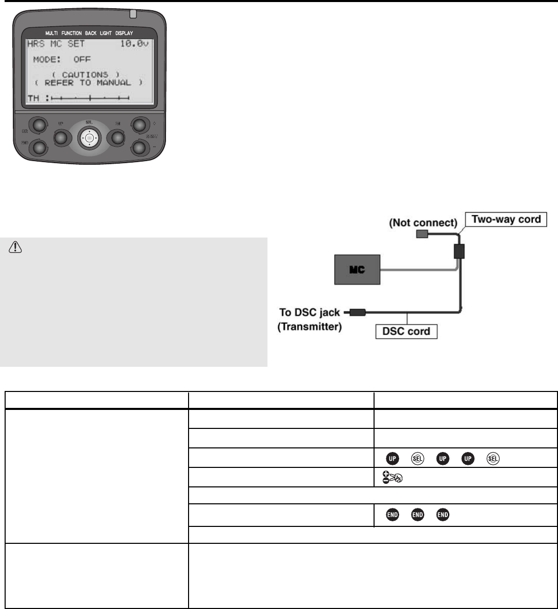
Fine Tuning ESC Readability (for HRS receivers ONLY) MC-SETUP Level LV3 Only
DEFINITION: Adjusts frame rate of transmitter output to throttle channel for
setting up non-Futaba ESCs with HRS systems. HRS frame rate is faster than all
other products currently sold in the US, and some non-Futaba speed controls can
not properly read the output to complete their auto setups, making setup difficult.
AVAILABLE FOR: HRS receivers ONLY.
ADJUSTABILITY: N/A.
INTERACTION: Must be used only with HRS receivers, and only with speed
control properly connected, using the proper cords (not included), as shown below.
DESIRED END RESULT: Quick, easy setup of non-
Futaba ESCs with HRS receivers.
CAUTIONS:
• ONLY use with HRS receivers/modulation.
• MUST use the two-way cord and DSC cord to
connect ESC directly to transmitter to complete
this setup.
• Transmitter switch MUST be turned off after setup
is executed or the amp mode cannot be reset and
the system can not transmit properly. Warning will
display “CAUTION! NOW MOD OFF”.
44
GOAL:
Complete auto-setup of a non-Futaba ESC
that is not setting up properly on its own
when in use with an HRS receiver, while
using LV3. (If using LV1 or LV2, first select
level LV3, see p. 12.)
Where Next:
STEPS:
Be sure transmitter is in HRS mode.
Set up DSC/two-way cord.
Select MC-SETUP function.
Activate amp setup.
Adjust front delay to 10.
Close function and menu.
INPUTS:
See modulation, p. 16.
See setup diagram above.
for at least one second.
Adjust subtrim until motor is not spinning at neutral (SUB-TRIM): See p. 22.
Setup ABS braking (ABS): See p. 24.
Adjust throttle/ESC speed to minimize wheel spin (TH-SPEED): See p. 23.
Setup throttle acceleration for spin-free starts (TH-ACCEL): See p. 26.
Follow manufacturer’s auto-setup instructions for ESC.
TURN TRANSMITTER OFF. (Transmitter can not transmit until power is cycled.)
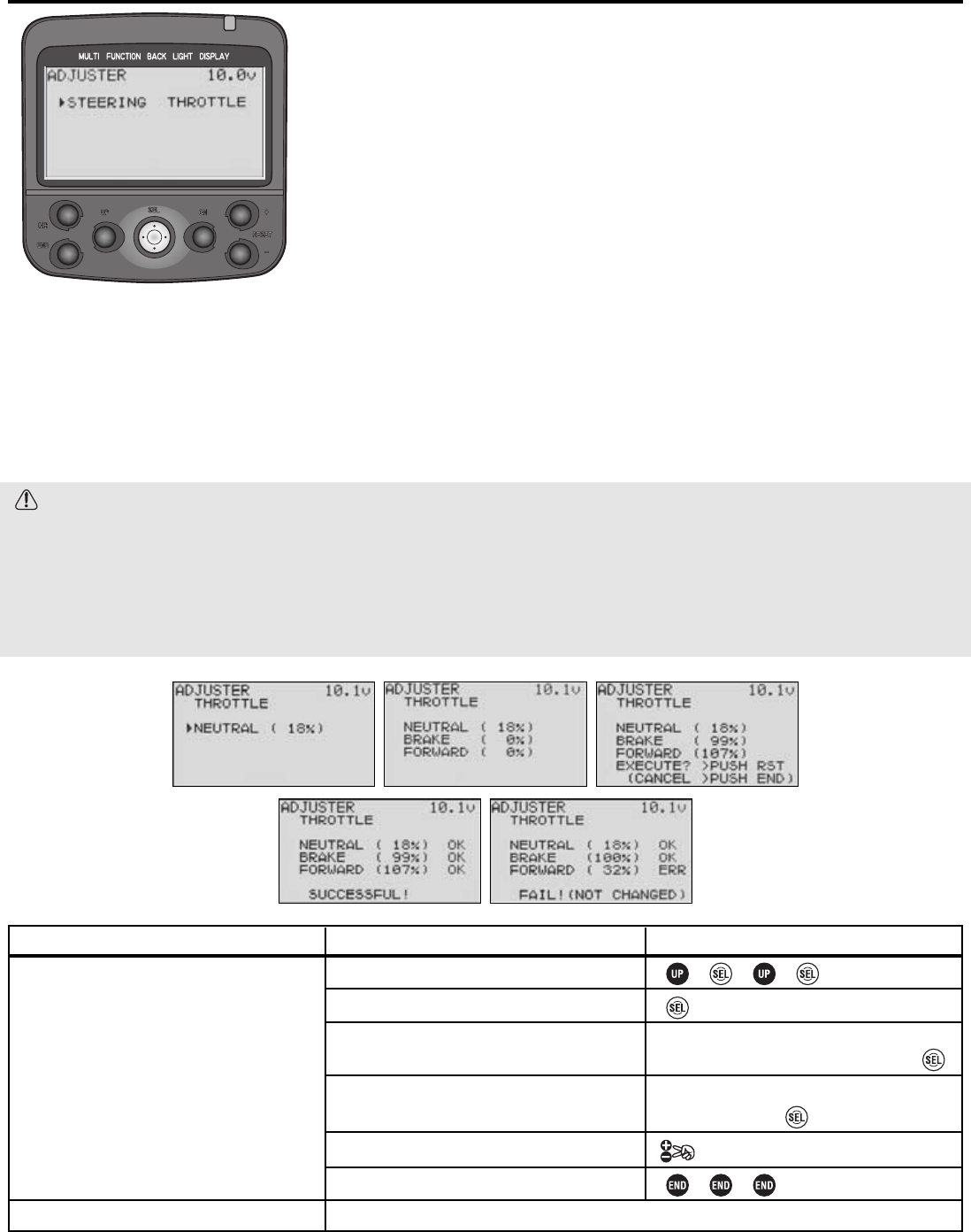
Level LV3 Only Electronic Centering Calibration Adjuster ADJUSTER
DEFINITION: Calibrates electronic positioning to mechanical movement of
controls. Even if you never have a crash, your R/C vehicle needs occasional
alignments and mechanical adjustments to keep it “in tune” and in trim.
Similarly, all transmitters need regular maintenance to keep everything properly
aligned. But unlike all other transmitters which just have to be driven “as is”
until professionally adjusted/repaired, you can temporarily adjust your 3PK to
keep driving as if it were new, then happily wait until your non-racing season
when you can send it for its regular maintenance.
AVAILABLE FOR: Throttle, steering.
ADJUSTABILITY: Neutral and left/right vs. neutral/brake.
INTERACTION: Adjuster affects the mechanical position the radio thinks is center/neutral, and also the end points.
Correcting any minor slippage/wear in the transmitter with adjuster will temporarily correct the out of trim problems until
the radio can be serviced. All programming functions operate based upon the radio’s neutral and full left/right or
neutral/brake positioning.
DESIRED END RESULT: Correct for minor slippage/wear/drift in the steering and throttle to provide like-new performance.
CAUTIONS:
• Need for regular service: Slippage is a sign of wear to the transmitter. Be sure to have your radio serviced
regularly (we recommend annually) to check for/service other wear and tear on the radio and also to ensure
proper transmitter tuning.
• Correction range: If the adjustment point shown is not close to the default settings (100%, 0, 100%), the system
will not store the new positions, and an error message of “FAIL! NOT CHANGED” is displayed. Retry process. If
data can not be stored, the radio is too far out of alignment to use. Send for service promptly (see p. 4).
45
GOAL:
Complete software adjustment to fix steering
mechanical offset.
Where Next:
STEPS:
Open menu 3 and select adjuster.
Select steering.
Set steering neutral.
Set left and right ranges.
Confirm desired correction.
Close function and menu.
INPUTS:
Lightly pull on the steering wheel, pulling it
away from the transmitter. Let go and
Lightly turn wheel full left, let go, turn full
right. Let go and
Back to the track!

46
Application, Export, and Modification
1. This product is designed for surface models only. It is not intended for use in any application other than the control of
surface models for hobby and recreational purposes. The product is subject to regulations of the Ministry of
Radio/Telecommunications and is restricted under Japanese law to such purposes. It is also subject to the regulations of the
FCC and is restricted under U.S. law to such purposes.
2. Exportation precautions:
(a) When this product is exported from the country of manufacture, its use is to be approved by those laws of the country
of destination that govern devices that emit radio frequencies. If this product is then re-exported to other countries, it
may be subject to restrictions on such export. Prior approval of the appropriate government authorities may be required.
If you have purchased this product from an exporter outside your country, and not the authorized Futaba distributor in
your country, please contact the seller immediately to determine if such export regulations have been met.
(b) Use of this product with other than models may be restricted by Export and Trade Control Regulations, and an application
for export approval must be submitted. In the US, use of 72MHz (aircraft only), 75MHz (ground models only) and 27MHz
(both) frequency bands are strictly regulated by the FCC. This equipment must not be utilized to operate equipment other than
radio controlled models. Similarly, other frequencies (except 50MHz, for HAM operators) must not be used to operate models.
3. Modification, adjustment, and replacement of parts: Futaba is not responsible for unauthorized modification, adjustment, and
replacement of parts on this product. Any such changes may void the warranty.
Liability, Warranty
1. Please see the enclosed warranty card for detailed information on warranty coverage. If you have questions,
please contact our service facility at the addresses provided on page 4.
2. Futaba and its agents are not responsible or liable for the use of this product in any manner.
3. Futaba does not guarantee compatibility with any non-Futaba product and Futaba will not be responsible for
problems caused by the use of non-Futaba parts or equipment in conjunction with this radio system.
4. Opening, modifying, repairing, replacing parts, or otherwise making any use of each component other than as
described in this manual, voids the warranty for that component. Futaba is not responsible for any such
modifications, etc
The Following Statement Applies to the Receiver (for U.S.A.)
This device complies with Part 15 of the FCC rules. Operation is subject to the following two conditions:
(1) This device may not cause harmful interference, and
(2) This device must accept any interference received, including interference that may cause undesirable operation.
Battery Recycling
The RBRC™SEAL on the nickel-cadmium battery contained in Futaba products indicates that Futaba
Corporation of America is voluntarily participating in an industry-wide program to collect and recycle these
batteries at the end of their useful lives, when taken out of service within the United States. The RBRC™
program provides a convenient alternative to placing used nickel-cadmium batteries into the trash or municipal
waste system, which is illegal in some areas.
(for USA)
You may contact your local recycling center for information on where to return the spent battery. Please call
1-800-8-BATTERY for information on NiCd battery recycling in your area. Futaba Corporation of America’s involvement
in this program is part of its commitment to protecting our environment and conserving natural resources.
NOTE: Our instruction manuals encourage our customers to return spent batteries to a local recycling center in order to
keep a healthy environment.
RBRC is a trademark of the Rechargeable Battery Recycling Corporation.
APPENDIX I
Precautions and Warnings

47
MEANING OF SPECIAL MARKINGS
Pay special attention to safety where indicated by the following marks:
DANGER - Procedures which may lead to dangerous conditions and cause death/serious injury if not carried out properly.
WARNING - Procedures which may lead to a dangerous condition or cause death or serious injury to the user if not
carried out properly, or procedures where the probability of superficial injury or physical damage is high.
CAUTION - Procedures where the possibility of serious injury to the user is small, but there is a danger of injury, or
physical damage, if not carried out properly.
= Prohibited = Mandatory
Warning: Always keep electrical components away from small children.
To ensure the safety of yourself and others, please observe the following precautions:
Have regular maintenance performed. Although your radio does not have a battery to protect the model memories,
it still should have regular checkups for wear and tear. In the US, we recommend sending your system to the US
Futaba Service Center annually for a complete checkup and service.
CAUTION - Before Using Your System…
1. ALWAYS be sure the receiver, servo(s), ESC, crystal and connectors are fully connected prior to every operation.
Vibration, which occurs in all models, means regular inspections and maintenance are critical.
2. ALWAYS protect the receiver and NiCd battery from vibration by mounting them in thick double-sided tape or foam.
3. Aquatic users: ALWAYS protect all radio equipment from potential water damage by waterproofing. Send any
equipment subjected to water, fuel or other corrosive materials for testing prior to re-use.
4. NEVER cut or coil your receiver antenna or bundle it with any servo leads, battery wires, carbon fiber, metal or
other conductive materials.
5. ALWAYS keep the receiver antenna at least 1” away from motor/battery/ignition/other wiring carrying heavy current.
6. Electric Users: ALWAYS install the ESC heat sinks such that they can not come into contact with plastic,
aluminum, carbon fiber, or other conductive materials, or a short circuit may occur.
7. ALWAYS operate each servo full distance both ways and check for buzzing, binding, loose linkages, chatter, or
“stepping” in the movement (check for broken servo gears).
8. ALWAYS use the rubber grommets for servo installation, and ensure the servos do not come into direct contact
with the mount or anything that conducts electricity.
9. Electric Users: ALWAYS install capacitors on electric motors to suppress electrical noise.
10. ALWAYS inspect your model for metal-to-metal contact (including while engine/motor is running) which could
create electrical noise and result in erratic system operation.
11. ALWAYS range check your system.
12. NEVER leave the radio system or models within reach of small children. NiCd batteries can be very dangerous
when mishandled and can cause chemical damage.
13. NEVER store your radio equipment and models where they will be exposed to extreme heat or cold, direct
sunlight, high humidity, large quantities of dust, steam or condensation.
14. NEVER expose the plastic parts of your radio system to raw fuel, oil, exhaust, water.
15. NEVER touch the engine, motor, speed control, or any other part of the model which generates heat during
operation until the model is not operating, has been fully turned off and allowed to cool. These parts may be very
hot and can cause serious burns.
16. ALWAYS display a frequency flag when operating your model.
17. NEVER operate this R/C system when you are tired, not feeling well, or under the influence of alcohol or drugs.
18. NEVER operate near other radio control activity areas, on any ponds or lakes where rowboats or swimmers are
present, or near high tension power lines or communications broadcasting antennas.

48
Charge the batteries! (See Caring for your NiCd batteries, p. 49, for details.) Always recharge the transmitter and
receiver batteries for at least 8 hours before each session. A low battery will soon die, causing loss of control and a
crash. When you begin your session, reset your radio's built-in timer, and during the session pay attention to the
duration of usage.
Stop operating your radio long before your batteries become low on charge. Do NOT rely on your radio’s low
battery warning systems, intended only as a precaution, to tell you when to recharge. Always check your
transmitter and receiver batteries prior to each use.
Before operating, make sure that your frequency is not already in use, and secure any frequency control device
(pin, tag, etc.) for that frequency before turning on your transmitter. It is never possible to operate two or more
models on the same frequency at the same time. Even though there are different types of modulation (AM, FM,
PCM) and brands, only one model may be operated on a single frequency at any one time.
To prevent possible damage to your radio gear, turn the power switches on and off in the proper sequence:
1. Position throttle at idle, or otherwise disarm your motor/engine.
2. Turn on the transmitter power and allow your transmitter to reach its home screen (if applicable.)
3. Confirm the proper model memory has been selected (if applicable.)
4. Fully extend the transmitter antenna.
5. Turn on your receiver power or speed control power switch.
6. Test all controls. If a servo operates abnormally, don’t use until you determine the cause of the problem. (For PCM
and HRS systems only: Test to ensure that the FailSafe settings are correct by waiting at least 2 minutes after
adjusting; then, turn the transmitter off and confirm the proper servo movements. Turn the transmitter back on. See
page 17 for details on FailSafe functions.)
7. Complete a full range check.
8. After use, bring your throttle to idle, engage any kill switches or otherwise disarm your motor/engine.
9. Turn off receiver power.
10. Turn off transmitter power.
If you do not turn on your system in this order, you may damage your servos or control surfaces, flood your engine, or in the
case of electric-powered or gasoline-powered models, the engine may unexpectedly turn on and cause a severe injury.
If you place your transmitter on the ground, be sure that the wind won’t tip it over. If it is knocked over, controls
may be accidentally moved. Also, damage to your transmitter may occur.
Before running the model, be sure to extend the transmitter antenna to its full length. A collapsed antenna will
reduce your range and cause a loss of control. Try to avoid pointing the transmitter antenna directly at the model, since the
signal is weakest in that direction.
Don’t operate in the rain, drive unprotected electronics through puddles or use when visibility is limited! Water or
moisture may enter the transmitter through the antenna or other openings and cause erratic operation or loss of control. If you
must use in wet weather during a contest, be sure to cover your transmitter with a plastic bag or waterproof barrier. Never use
if lightning is expected.
MANDATORY PROCEDURES for use with the High Response System (HRS) receivers
Use ONLY:
•Servos: Unregulated 6-Volt compatible Digital servos
•Battery: 6-Volt Unregulated NiCd or NiMH battery
•Mode: Transmitter MUST be set to HRS mode (see p. 7 and p.16 for details)
•Transmitter: Futaba’s 3PK is the first radio sold in the US with HRS capability. At this time, only the 3PK may be
used with the HRS receivers. Be sure to check any other transmitter’s operator’s manual before attempting to use with
an HRS receiver.
•NOTE: Do not attempt to operate with the Futaba FailSafe Unit (FS1) with an HRS receiver. Instead use the FailSafe
settings built into the transmitter. (see p. 17 for details.)
49
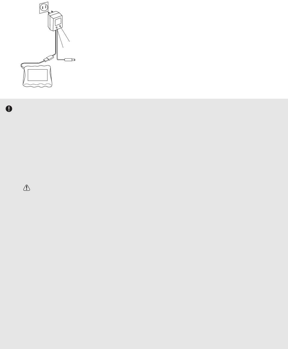
CARING FOR YOUR NiCd BATTERIES
Charging Your System’s Batteries
1. Connect the transmitter charging jack and receiver
NiCd batteries to the transmitter and receiver
connectors of the charger.
2. Plug the charger into a wall socket.
3. Check that the charger LED lights.
The initial charge, and any charge after a complete discharge,
should be at least 18 hours to ensure full charge. The
batteries should be left on charge for about 15 hours when
recharging the standard NiCd batteries after normal use.
You should fully discharge your system’s batteries periodically to prevent a condition called memory. If you
regularly use only a small amount of the battery's capacity, the memory effect can reduce the actual capacity even if the
battery is fully charged. You can cycle your batteries with a commercial cycling unit*, or by leaving the system on and
exercising the servos by moving the transmitter sticks until the transmitter shuts itself off. Cycling should be done every
four to eight weeks, even during the winter or periods of long storage. Keep track of the batteries’ capacity during cycling;
if there is a noticeable change, you may need to replace the batteries.
*Note that your 3PK transmitter system is protected from overcharge. If the battery is charged with a quick charger for
other than digital RC systems, it may not be fully charged.
NiCd Handling Precautions
•CAUTION - NiCd electrolyte is a strong alkali. Should you come in contact with even the smallest amount:
•EYES: DO NOT RUB, wash immediately with water, and seek medical attention at once. The electrolyte can
cause blindness.
•CLOTHING/SKIN: Wash with water immediately. Seek medical attention if rash occurs.
•DO NOT attempt to charge your 8-cell transmitter pack on the 4-cell receiver plug of the wall charger!
•NEVER plug charger into an outlet other than the standard voltage (US is 110V).
•NEVER insert or remove the charger while your hands are wet.
•ALWAYS use the provided charger or a quick charger specifically for remote control modeling. Overcharged
NiCds can result in severe burns, fire, breakage, or electrolyte leakage.
•NEVER try to recharge an alkaline dry cell battery.
•ALWAYS disconnect the radio from the charger and the charger from the wall when not in use.
•ALWAYS double-check that your batteries are fully charged prior to use.
•ALWAYS remove or disconnect the receiver NiCd when the vehicle is not in use to avoid accidental turn-ons.
•NEVER use commercially provided single NiCd battery cells. Charging these cells in your R/C system or with
R/C system chargers may result in damage to the equipment and chargers.
•NEVER drop the NiCd battery or expose it to strong shock or vibration. Crashed equipment should always be sent
for service to test for internal damage.
•NEVER leave the R/C system or batteries within the reach of small children.
•ALWAYS store the system with the batteries in a discharged state and in a cool/dry place.
•ALWAYS remove the transmitter and receiver batteries from the transmitter/vehicle for long-term storage.
Charger
TX: Transmitter charging indicato
r
RX: Receiver charging indicator
To transmitter charging jack
Receiver Ni-Cd battery
50
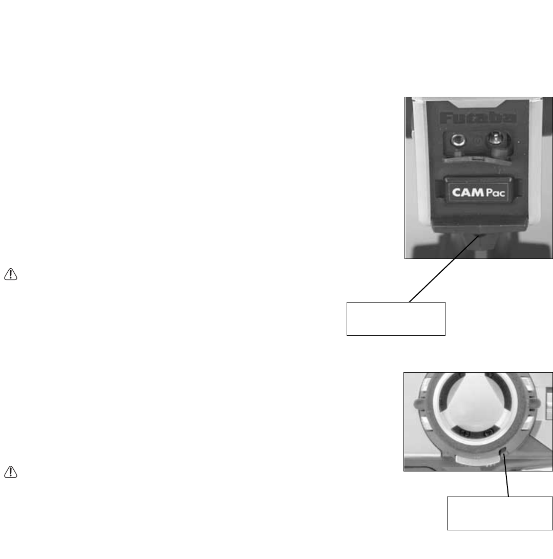
Mechanical ATL Adjustment: Make this adjustment when you want to decrease the total travel of the brake (push) side
of the throttle trigger. For digital ATL, see p. 37.
Note: This is a mechanical stop screw only, and does not move the neutral point or affect
the acceleration (pull) side of the throttle trigger. Creating a shorter stroke allows for
more rapid response when the linkage or end point is adjusted to create the same total
servo travel.
Adjustment: Using a Phillips screwdriver, adjust the trigger brake (back) stroke by
turning the screw through the adjusting hole indicated by the arrow in the figure. (The
screw moves the throttle trigger stopper.)
•When the adjusting screw is turned clockwise, the stroke becomes narrower. Make
this adjustment when you want to make the throttle trigger brake (back) stroke smaller
(more responsive).
CAUTION - When the stroke is adjusted, the throttle servo travel must be adjusted by linkage or programmed setting
to gain the same total movement.
Wheel Tension Adjustment: Make this adjustment when you want to change the steering
wheel spring tension.
Adjustment: Turn the screw inside the adjusting hole using a 1.5mm hex wrench.
•Turning the adjusting screw clockwise increases the spring tension.
CAUTION - If turned too far counterclockwise, the adjusting screw may fall out.
Note: To adjust the wheel and trigger calibration, see ADJUSTER p. 45.
Mechanical ATL
adjusting screw
Tension adjusting
screw
APPENDIX II
Adjustments, modifications and replacements
51
•Changing the wheel position
The wheel position can be offset by
using the included accessory offset
adapter. The wheel angle can also
be adjusted.
•Modification for left-hand use
The wheel section can be moved to
the back of the transmitter for
left-handed operation.
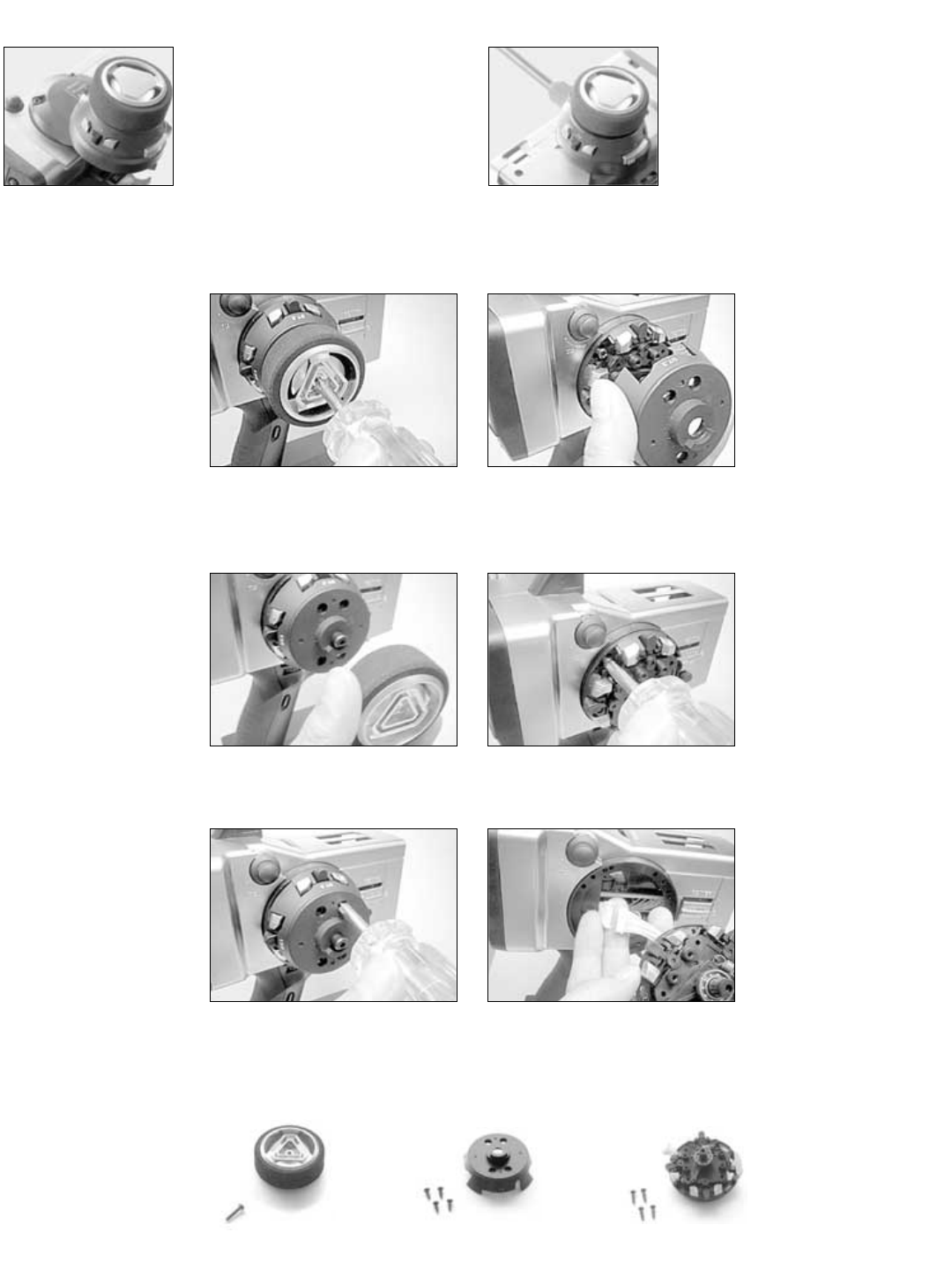
1. After removing the wheel cap,
carefully remove the screw
holding the steering wheel.
2. Remove the steering wheel.
3. Remove the 4 screws from the
wheel unit cover.
4. Remove the wheel unit cover.
Be very careful or the wheel
shaft will fall out.
5. Remove the 4 screws from the
wheel unit.
6. Disconnect the wheel unit
wiring harness.
Steering Wheel
screw (large) x1
Wheel Unit Cover
screw (small) x4
Wheel Unit
screw (middle) x4
CHANGING WHEEL POSITION/MODIFYING FOR LEFT-HAND USE
Removing the steering wheel unit
52
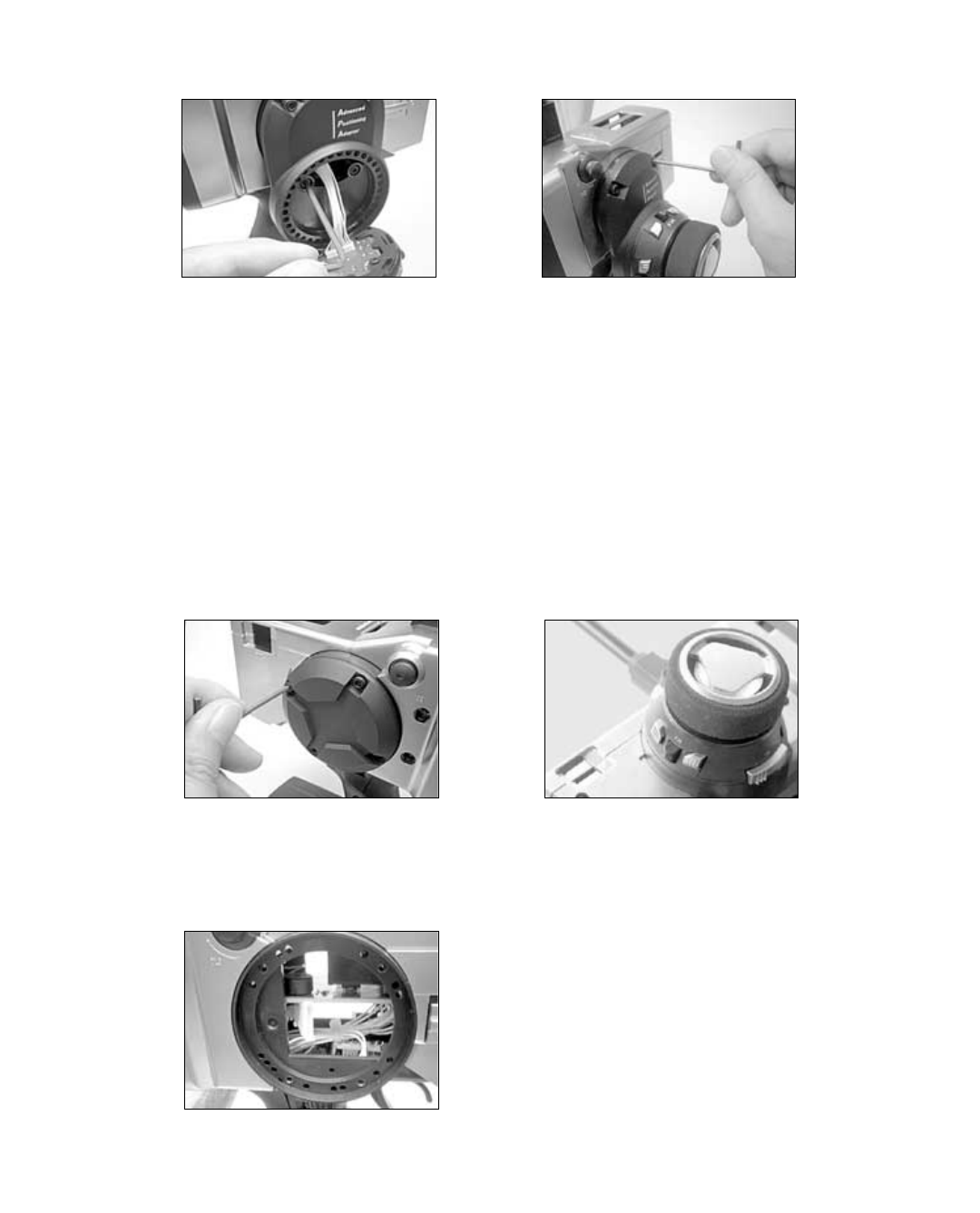
Changing wheel position
Modifying for left-hand use
1. Connect the wheel unit wiring harness
through the offset adapter. Install the adapter
using four 2.5mm hex bolts attached.
2. Reinstall the wheel unit, wheel unit
cover, wheel, and wheel cap in same
position as they were removed.
1. Remove the wheel back cover using
2.5mm hex wrench.
2. Push the wheel unit wiring harness in the
opposite side.
3. In opposite side, connect the wheel unit
wiring harness and reinstall the wheel unit,
wheel unit cover, wheel, and wheel cap in
the same position as they were removed.
53
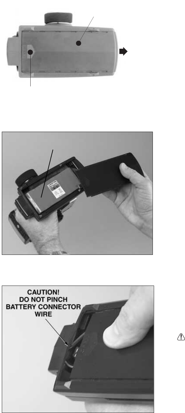
Battery Replacement
1. Slide the transmitter battery cover in the arrow
direction while pressing the part shown in the figure.
2. Replace the NiCd battery pack or dry cell batteries.
3. Slide the battery cover back onto the transmitter.
NiCd Battery system
The NiCd battery is connected by a connector so that it
can be removed when you will not be using the
transmitter for a long period of time, or when
replacing a discharged battery with a spare battery.
CAUTION - DO NOT pinch the NiCd battery wire
when sliding the lid closed. If the wire is damaged,
abnormal heating and fire may result.
B
a
tt
e
r
y
c
o
v
e
r
While pressing this part.
FUTM1462
SLIDE
54
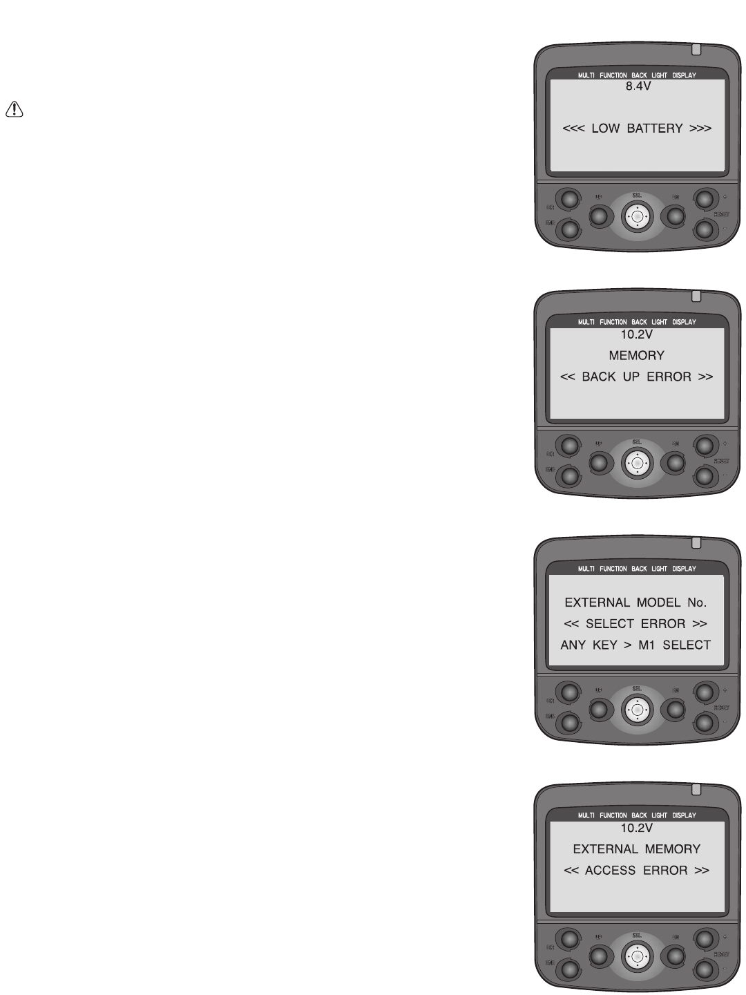
Low Battery Alarm:
•If the transmitter’s battery voltage drops below 8.5V an alarm will sound and
“LOW BATTERY” will be displayed on the LCD screen.
CAUTION The low battery alarm is meant to be a safety feature only. Do NOT
operate your radio below 9V and count on the low battery warning to let you
know it is time to charge! Always shut your radio off as soon as possible after
the low battery warning tone to avoid loss of control.
• Alarm tone: continuous tone.
Backup Error:
•MEMORY “BACK UP ERROR” displays on screen if the EEPROM-stored data is
lost for any reason. The 3PK does not use a battery to store this data; it is
stored in permanent non-volatile memory. However, failures can still occur
which cause loss of this memory. If a backup error occurs, immediately stop
using the transmitter and send it for service. Do not attempt to continue to
use the radio.
•Alarm tone: 9 beeps, pause, repeat.
Model Select Error:
•EXTERNAL MODEL # “SELECT ERROR” ANY KEY > M1 SELECT displays when the
following occurs:
• Model being operated is stored in the CAMPac.
• Transmitter is turned off, and CAMPac removed.
• Transmitter is then turned back on.
The transmitter is unable to read the last model used (because it is in the CAMPac),
and so it provides a warning that it cannot select the last model memory used and
then selects model M1.
•Alarm tone: 7 beeps, pause, repeat.
CAMPac Error:
•EXTERNAL MEMORY “ACCESS ERROR” displays when a problem occurred
while copying from or to the CAMPac.
•To stop the alarm, turn off the transmitter. Turn it back on. Repeat the copy
attempt to ensure all data was safely copied.
•Alarm tone: 7 beeps, pause, repeat.
APPENDIX III
Error Displays
55
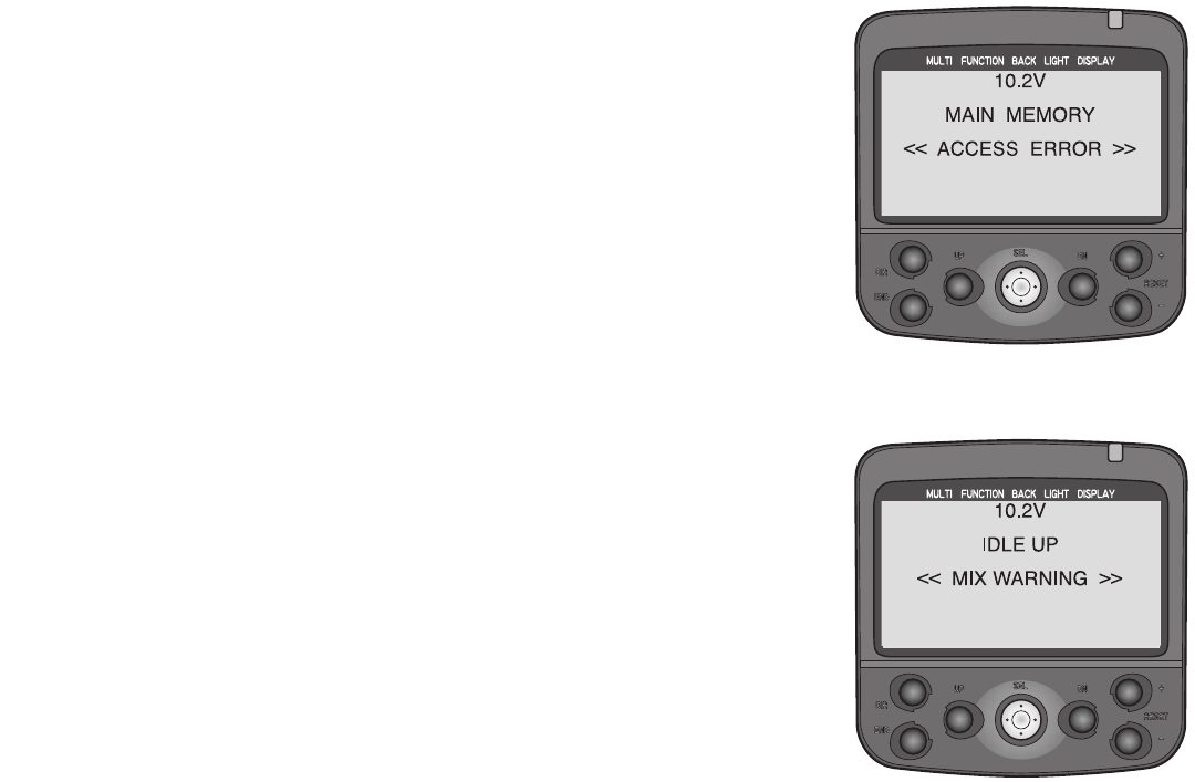
Idle-Up Warning:
•IDLE UP “MIX WARNING” displays if the idle up mix is turned on when the
transmitter is turned on.
•To stop the alarm, move the idle-up switch to off.
•Alarm tone: 7 beeps, pause, repeat.
Memory Error:
•MAIN MEMORY “ACCESS ERROR” displays when the transmitter is turned on
and a problem occurs with accessing a model.
•To stop the alarm, turn off the transmitter. Turn it back on. If the alarm
sounds again, send for service. If it does not, the system is ready for use.
•Alarm tone: 7 beeps, pause, repeat.

56
GLOSSARY and INDEX
3CH: Channel 3 position. See channel 3 assignment. .........................................................................................................40
3-channel: transmitter that can send commands to 3 separate channels for model operation.
ABP: Adjustment in ABS. Amount of brake return, how far the braking response is decreased during the pulses. 0 = no
return, no ABS action; 100% = completely returned to neutral, no braking at all during pulses. See ABS.......................24
ABS: Anti-lock braking system. Simulates full size automobile anti-lock brakes by pulsating the brakes. Length of pulse
cycles, amount of brake return (easing off brake), ratio of brake return to full brake on, delay before ABS takes effect, and
trigger position where ABS takes effect can all be adjusted................................................................................................24
ABSD: ABS delay. See ABS. ..............................................................................................................................................24
ACCB: Acceleration, braking. See Throttle Acceleration...................................................................................................26
ACCF: Acceleration, forward. See Throttle Acceleration. .................................................................................................26
Acceleration: See Throttle Acceleration .............................................................................................................................26
ACT: Activated. Used in various functions.
Additional Technical Help, Support and Service ..............................................................................................................4
Adjustable Throttle Limiter: See ATL..............................................................................................................................37
Adjuster: Electronic calibration to compensate for minor wear on the radio. ...................................................................45
Alarm Buzzer: See BUZZ-TONE.......................................................................................................................................12
ALRM: Total run time prior to desired alarm. See Timer...................................................................................................30
Application, Export and Reconstruction..........................................................................................................................46
AT&SW: Mode choice in Auto-start. Auto-start is activated by throttle trigger or switch. Switch can be assigned in FUNC-
SW and used to turn off the Auto-start feature without having to gun the throttle to do so. See AT-START....................28
ATL: Adjustable Throttle Limiter. Feature that adjusts the amount of travel available to the braking side only of the
throttle/braking trigger or servo.
Mechanical: stopper that blocks the brake trigger from moving as far away from neutral ..................................50
Electronic: end point adjustment which shortens the total travel to the brake side of the servo ..........................37
ATS: Auto-start Status. Whether auto-start is ‘armed’ and ready for use or waiting to be ‘armed.’ See Auto-Start.........28
AT-START/Engine cut: Auto-start function only allows the throttle servo to go to a certain preset point when starting a
race. This keeps it from accelerating too hard and spinning or torquing, wasting power. Engine cut shuts engine off with
push of a switch by taking the throttle servo to a preset location which closes the carburetor. (Engine cut is not available
on models using a single servo to operate throttle and brakes together.) ............................................................................28
ATV: Adjustable Travel Volume. See EPA ..........................................................................................................................18
Auto-Start: see AT-START .................................................................................................................................................28
Backlash: Term describing the amount of play between gears, or gear mesh. If too loose, the gear can slip, or strip the
teeth. Too tight, and excessive wear is caused.
Backlight: Display screen can be lit up, making it easier to read in indoor and other conditions. Backlighting adjustments:
contrast, constant on or on with keystroke, length on per keystroke and when lit. See System. ........................................13
Ball Bearing Servos: Servo’s output shaft is supported with ball bearings for increased performance and accuracy.
Ball Link: Connection using a ball and a socket that rotates on the ball. Used to connect the servo to a control surface or lever.
BALN: balance. In brake mix, decreases the amount of brake command to either front or rear without adjusting total brake
mix, etc. See Brake Mix .......................................................................................................................................................42

Base Load Antenna: A rigid, short antenna mounted to the model. Used to replace the longer stock antenna. Not
recommended or supported by Futaba.
Battery FailSafe: Notifies user when receiver voltage is low............................................................................................17
Battery Recycling................................................................................................................................................................46
BEC: Battery Eliminator Circuitry. Allows receiver to draw power from a main battery pack, eliminating the need for (and
weight of) a receiver battery.
Binding: What occurs when the friction at a joint is stronger than the linkage.
BK-BL: Brake mixing balance. See Brake Mix. .................................................................................................................42
BK-DL: Brake mixing delay. See Brake Mix......................................................................................................................42
BK-RT: Brake mixing rate. See Brake Mix. .......................................................................................................................42
Boat mode: A menu of features specifically for boat modelers. Includes trigger-brake and tilt mixing. ..........................43
Brake mix: Built in programmable mixing to use channels 2 and 3 for separately adjustable front and rear brakes. .....42
BRAKE-MIX: See Brake Mix. ...........................................................................................................................................42
Brightness: See Contrast. ....................................................................................................................................................13
BRK-EXP: See Exponential Rate. ......................................................................................................................................20
BUZ-TONE: Buzzer tone adjustment. See System.............................................................................................................13
Calibration: See Adjuster....................................................................................................................................................45
CAMPac ©:Removable memory storage (diskette) to store 10 additional model memories..............................................5
Carburetor: The part of the engine which controls the speed or throttle setting and lean/rich mixture via setting of the
needle valve.
Caring for your NiCd Batteries.........................................................................................................................................49
CH3-Posi: Moves the channel 3 center position or overall position if channel 3 is unassigned to any dials or switches..............40
Changing Wheel Position and Modifying for Left Hand Use ........................................................................................51
Channel: The frequency number used by the transmitter to send signals to the receiver. If 2 or more radios transmit on the
same frequency, or channel, glitching will occur in the receiver, due to conflicting signals sent by the two radios. Racing
sites should have a frequency control system to ensure that only one radio operates on any given channel at one time. This
is usually a board with some type of marker for each channel. If the marker is not available, someone else is using that
channel. Do not use your radio unless you are sure you are the only one on the frequency.
Channel: The number of functions your radio can control. Ex: A 3-channel radio has 3 available servo slots used for separate
control surfaces or switches. These channels can also be mixed on many radios, for such functions as multi-servo braking.
Channel 1 > 3: In boat mode, mix from steering (rudder) to outboard. See Boat Mode. ..................................................43
Channel 3 > 1: In boat mode, mixing from outboard to steering (rudder). See Boat Mode. .............................................43
Channel 3 assignment.........................................................................................................................................................40
Charge Jack: The plug receptacle of the switch harness into which the charger is plugged to charge the receiver battery.
An expanded scale voltmeter (ESV) can also be plugged into it to check battery voltage between uses. It is advisable to
mount the charge jack in an accessible area of the model so an ESV can be used without extensive disassembly.
57

Charger: Device used to recharge batteries. Usually supplied with the radio if NiCd batteries are included.
CH-EPA: Channel End Point Adjustment. See EPA...........................................................................................................18
CH-REV: Channel Reversing. See Servo Reversing. .........................................................................................................18
Color: Color for LED lamp is adjustable. See LED-MODE. .............................................................................................13
Contents and Technical Specifications................................................................................................................................5
Contrast: LCD screen contrast. See System. ......................................................................................................................13
Coreless Motor: In a conventional servo, the motor has a steel core armature wrapped in wire that spins inside the
magnets. In a coreless design, the armature uses a thin wire mesh that forms a cup that spins around the outside of the
magnet eliminating the heavy steel core. A coreless motor does not have magnets as standard servo motors do, so they have
a smoother, more constant, and stronger action. Regular servo motors have either 3 or 5 magnets (poles) which, when the
armature is between these, the servo motor is at its weakest.
Count Down Timer: See Timer ..........................................................................................................................................30
Count Up Timer: See Timer ...............................................................................................................................................30
Curve: In throttle exponential, the “curve” function offers 5 points along the range of the servo, and draws straight lines
of response between each point. It is not a true curve, as is exponential, and there are noticeable steps in the responsiveness
as each rate of response is entered. See Exponential. ..........................................................................................................20
CUT OFF: No braking action when trigger is pushed forward. Adjustment within Boat Mode. See Boat Mode............43
CYC: Adjustment in ABS. Cycle adjustment, sets how rapidly the brakes cycle from full brake applied to ABP and back
to full brake applied. See ABS. ............................................................................................................................................24
Cycle: Adjustment in ABS. One complete “pulse” of maximum brake applied to lessened brake. See ABS...................24
D/R2: 2nd steering dual rate. See Steering Dual Rate.........................................................................................................38
DELAY: In brake mix, waits to send command to either front or rear, allowing other to begin braking the car first. See
Brake Mix. In ABS, see DLY. ..............................................................................................................................................24
Differential. Uneven movement in each direction of a control. For example, differential steering in a 4WD car (see
programmable mixing example, p. 40.) or differential braking (see brake mix, p. 42.)
Digital Grip Dial Operation.................................................................................................................................................9
Digital Servo: Servo with a quartz crystal-controlled microprocessor, FET amplifier and specialized lead rather than a
standard logic chip and timing components of a standard servo. Sends signals to the servo motor 6 times faster than analog
servos. Required for use with HRS receivers.
Digital Trim Operation.........................................................................................................................................................9
Digital Trims and Dials: Electronic switches which automatically store their position each time a change is made.
Separate memories for each trim and dial exist in each model memory. ..............................................................................9
DIRC-CALL: Direct Select menu setup. Assigns the 6 features to the direct select menu for each selection. ................36
Direct Selection Menu: Quick access menu that allows user access to any 6 features with the push of 2 buttons.........11
Direct Servo Control (DSC). High-end convenience feature that allows control/adjustment of servo function without sending
signal through receiver. Requires optional DSC cord and DSC-compatible receiver such as R113iP, R113F, R123F, R133F. .......5
DISP: display only. Transmitter is operating the programming display only and is not transmitting RF to the receiver............8
Display Settings: See System..............................................................................................................................................13
Display Switch .......................................................................................................................................................................8
58

DISPL-SEL: Home screen display settings. See System....................................................................................................13
DLY: Adjustment in ABS. Delay; determines how long the braking is applied before ABS begins to operate. 0 = no delay;
100% = approximately 1.7 seconds full braking before pulsing begins. See ABS. ............................................................24
Down Timer: Count-down timer. Counts negatively once desired time is passed (below 0). Runs consecutively until reset
with lap reset or change of model selection. See Timer.......................................................................................................30
DPAC: Display indication that CAMPac is installed and being read by the transmitter. See Getting to Know the
Transmitter ..............................................................................................................................................................................5
D/R: See Dual Rate .............................................................................................................................................................38
DSC: See Direct Servo Control. ..........................................................................................................................................5
DTY: Adjustment in ABS. Cycle duty ratio, sets the proportion of brakes applied full vs. ABP. Setting of +3 provides least
time at full brake; -3 provides maximum time at full brake (more likely to skid). See ABS. ............................................24
Dual Brake Servos: See Brake Mix....................................................................................................................................42
Dual Rate, or Primary Dual Rate: Name of the first rate setting in dual rate function. Decreases the vehicle’s steering
sensitivity across the entire range. Equivalent of decreasing brake side EPA only by that percentage. Assigned to grip dial
1 as a default to allow on-the-course adjustments. If grip dial is reassigned, dual rate may still be adjusted on-screen. Dual
rate is always active, except when the 2nd dual rate switch is pushed. (3PK’s dual rate is the same as the 9Z’s AFR and the
first rate of dual rate in other aircraft radio models.) See Steering Dual Rate. ...................................................................38
Dual Rates: Adjustable rates of travel to fine-tune the model’s handling. Traditionally, dual rate on a car radio is used to
describe a single rate that can be adjusted while driving. Dual rates on aircraft radios, and on the 3PK, provide the user 2
separate amounts of travel available at the push of a switch. See Steering D/R .................................................................38
Dual Steering Servos: See Programmable Mixes...............................................................................................................40
Duty Ratio: See DTY in ABS.............................................................................................................................................24
E11-E20: Model numbering for model memories stored in the optional extended memory CAMPac. See Model Select ...........14
End Point Adjustment: See EPA. ......................................................................................................................................18
Engine Cut: Moves throttle servo to a preset position which closes the carburetor and shuts off the engine. Not functional
with models using a single servo to operate brakes and throttle. See AT-START ..............................................................28
EPA: Adjustment to the servo’s position when full input is given. Used when the mechanical setup in the vehicle does not
provide the exact desired amount of steering, or the throttle servo is trying to open the carburetor past wide open, or does
not open it far enough...........................................................................................................................................................18
Error Messages. ..................................................................................................................................................................54
ESC Setup for HRS receivers: See MC Setup. .................................................................................................................44
ESC: Electronic speed control used to vary electric motor RPM.
Expanded Scale Voltmeter (ESV): Device used to read the battery voltage of the on-board battery pack or transmitter
battery pack.
EXPB: Exponential, braking. See Exponential Rate ...........................................................................................................20
Expert Driver Menus: See Level Selection. ......................................................................................................................12
EXPF: Exponential, forward throttle. See Exponential Rate. .............................................................................................20
Exponential Rate: Offers servo travel that is not directly proportional to your inputs. When negative exponential is used,
control response is milder near neutral, but becomes increasing stronger as travel approaches 100%. Throttle exponential
offers 3 separate ‘curve’ types. ............................................................................................................................................20
EXPS: Exponential, steering. See Exponential Rate. ..........................................................................................................20
59

FailSafe: A safety feature that moves a servo to a preset position if the signal is lost or interrupted. Please refer to
(http://www.futabarc.com/faq/product-faq.html#q102) for more information. Additionally, Battery FailSafe is a safety feature
that brings the throttle servo down to idle as a warning that the receiver battery’s voltage is getting dangerously low. ..........17
F.A.Q.: Frequently asked questions. www.futabarc.com/faq/faq-3pk.html
Field Charger: A fast battery charger designed to work from a 12-volt power source, such as a car battery. Usually takes
advantage of peak charging capability.
FM: Frequency Modulation. This describes the type of transmission of radio signal from transmitter to receiver. PPM
(commonly called simply “FM”), PCM1024, and HRS all transmit with the FM type.
Frequency Control. The FCC has allowed the 75mHz band (75.410 - 75.990) to be used for R/C ground model operations,
and the 27mHz band (26.995 - 27.255) for ground and air models. This band is divided up into many different channels on
which you can choose a radio system. You should be aware that certain areas have frequencies in which there is pager and
other interference. This is why it is always a wise move to check with your local hobby shop to find out any channels that
may be troublesome in the area. The FCC has allocated the 50mHz band (50.800 - 50.980) only to Amateur HAM license
holders for R/C use (and only at 1W maximum power output.)
Frequently Asked Questions webpage: www.futabarc.com/faq/faq-3pk.html
FUNC-DIAL: See Function Assignment. ...........................................................................................................................34
FUNC-SW: See Function Assignment. ...............................................................................................................................34
Function: A programming option within the radio, such as exponential, brake mixing, etc.
Function Assignment: assigns functions to the 3 dials, 3 trimmers, and 3 switches on the radio. Note: upper right on home
screen displays assignments to dials 1-3 and trims 1-3. ......................................................................................................34
Futaba Service Center:.........................................................................................................................................................4
FWD-TYP: Adjustment within exponential, defines what expo curve type for forward acceleration. See Exponential. .20
Getting to Know the Transmitter........................................................................................................................................8
Glow Plug: The heat source for igniting the fuel/air mixture in the engine. When starting the engine a battery is used to
heat the filament. After the engine is running, the battery can be removed. The wire filament inside the plug is kept hot by
the “explosions” in the engine’s cylinder.
Help ........................................................................................................................................................................................4
High Response System: See HRS ..................................................................................................................................7, 48
HOLD: In FailSafe, instruction to receiver to maintain the last instruction provided by the transmitter before clean signal
was lost. See FailSafe. ..........................................................................................................................................................17
Home screen display settings: See DISP-SEL...................................................................................................................13
HRS: High Response System. Modulation that provides input to receiver 3 times faster than standard PPM (often called
FM) data transmission. MUST USE only 6.0V battery packs and all digital servos. .....................................................7, 48
60

Idle-up: Moves throttle servo to a preset position, a higher idle, to aid in starting the engine. .........................................27
IDLUP: Idle-up. See Idle-up................................................................................................................................................27
INH: Inhibited. Function is electronically prevented from working and will not operate until changed to another setting.
Installation...........................................................................................................................................................................10
KEY-ON: The display back-lights whenever a programming key is pressed. Length of time is adjustable with LHT-TIME.
See System............................................................................................................................................................................13
LAP: Current lap number. See Timer. .................................................................................................................................30
LAP-LIST:See Lap List.......................................................................................................................................................31
Lap List: Lists all stored laps for this model. Laps are stored by setting up Timer to a Lap Memory Timer, setting up a lap
start/stop in the functions screen, and then starting/running the timer while driving the vehicle. Note that lap list is NOT
reset when a model memory is reset. It must be reset manually (see instructions).............................................................31
Lap Memory Timer: Acts as a count-up timer, storing each lap and starting a new lap each time button is pressed, while
also maintaining a total run time count-up alarm, with a pre-alarm warning time. Stores up to 100 laps, visible on LAP-
LIST (see p. 31). Has a 3-second safety window where button press does not reset the lap. See Timer. ..........................30
LED-MODE: LED pilot lamp color. See System. ..............................................................................................................13
Lap Navigate Timer: Count-up timer which alarms at a set total run time, but also has a navigation alarm which alarms
every set interval (desired lap time), and then restarts the navigation alarm countdown on each button press or upon passing
each navigation alarm time. (Example: 4 minute track race, desired lap time is 30 seconds. Nav alarm goes off if lap counter
is not pressed before 30 seconds, then again after another 30 seconds, and so on until 4 minutes.) Great for practice-runs
and working toward a target track time. Does NOT store individual lap times. See Timer................................................30
LAP RESET: Switch assignment required to end timers and prepare them to be used again without having to go to timer
programming to do so. See Timer. .......................................................................................................................................30
LAP START: Switch assignment required to indicate start/stop, or the end of each lap in lap navigate and lap memory
timers. See Timer. .................................................................................................................................................................30
Left Hand Use .....................................................................................................................................................................51
Level Selection: Allows user to select one of three levels of complexity/completeness of the functions displayed. Provides
a new user only the most frequently needed functions; a race driver those functions most frequently used for racing; and
an expert user all the functionality of the radio....................................................................................................................12
LEVEL-SEL: See Level Selection......................................................................................................................................12
LHT-MODE: LCD backlighting mode. See System. .........................................................................................................13
LHT-TIME: LCD backlighting time period. See System. .................................................................................................13
Liability and Warranty ......................................................................................................................................................46
LV1 functions: New User level functions. Most commonly used functions of the radio in a single menu for easy access
without extra clutter and confusion. See Level Selection ....................................................................................................12
LV2 functions: Race-Ready User level functions. LV1 functions set together with most common racing adjustments in a pair
of menus for easy access without extra clutter and confusion. See Level Selection....................................................................12
LV3 functions: Expert user level functions. All features available to the radio in 3 easily-accessed menus. See Level Selection.....12
61

M1-M10: Model numbering for model memories stored within the transmitter’s memory, not in the optional CAMPac.
Mandatory Procedures for using with HRS receivers ................................................................................................5, 48
Master: In programmable mixing, the channel the other servo will follow. In brake mixing, the throttle channel’s braking
side. See Programmable Mixes ............................................................................................................................................40
MC Setup (for HRS receivers only): HRS provides a very rapid frame rate – faster than most non-Futaba ESCs are
designed to read/comprehend. Therefore, most non-Futaba ESCs’ self-setup procedures are unable to complete the self-
setups and self-tests properly at this high frame rate. The MC Setup function, along with a special cord (not included),
allow the receiver to communicate with the ESC temporarily at a slower frame rate so the ESC can properly set up and be
prepared to operate properly in HRS....................................................................................................................................44
MC-SETUP: See MC Setup................................................................................................................................................44
MDL-COPY: See Model Copy............................................................................................................................................33
MDL-NAME: See Model Name. ........................................................................................................................................15
MDL-RES: See Model Reset. .............................................................................................................................................32
MDL-SEL: See Model Selection.........................................................................................................................................14
Meaning of Special Markings............................................................................................................................................47
Mechanical ATL..................................................................................................................................................................50
Menu Complexity: See Level Selection .............................................................................................................................12
Menu Level: See Level Selection........................................................................................................................................12
Menus: 3PK offers two separate menu types – the Direct Select menu which offers access to your 6 favorite functions with
just 2 buttons; all of the features of the radio in 3 levels of complexity (Level 1, 2, 3). ....................................................11
Metal Gears: One or more drive gears within a servo that are made of one or multiple metal types. Metal gears tend to
wear more rapidly than nylon gears when in the same installation, and so require more frequent service to maintain
optimum accuracy; however, metal gears are more durable in the case of severe vibration, flutter, or physical shock.
mHz (Megahertz = million cycles per second): The unit of radio frequency. 75 mHz are surface frequencies; 72 mHz are
air frequencies; 27 mHz and 50 mHz can be used for either ground or air applications. Note: Use of the 50 mHz (ham radio)
band requires an FCC license. The 3PK is not available on 50 mHz.
Mix Mode: Option in programmable mixing. Selects whether slave moves exactly based upon the master channel’s control
movement (unmixed) or the master channel’s servo movements after any mixing (mixed). In brake mixing, determines
whether front brakes respond based solely on trigger position (UNMIX), or whether other functions’ adjustments to rear
brakes also affect front brakes (MIXED). See Programmable Mixes. ................................................................................40
Mixing: Allows a single input to control the operation of two or more servos that are plugged into separate channels.
Simplifies more involved setups. For example, brake mixing, which utilizes 2 servos, one for front wheel braking and one
for rear wheel braking, allows different amounts of braking to front and rear when the driver simply gives brake with the
trigger. 3PK has 2 free programmable mixes which could be used to set up 4-wheel steering, separate front and rear steering
with adjustable acumen, etc. See Programmable Mixes.......................................................................................................40
MOD-MODE: Function used to select modulation for each separate model memory. ....................................................16
MODE: Setting for this function at this time – typically inhibited or active. More extensive choices are available in some functions.
Model Copy: Makes a back up or duplicate copy of all model data. .................................................................................33
Model Name: Provides a 10-character name for the model for easily selecting the right model memory. .......................15
Model Reset: Resets nearly all data associated with the currently-selected model memory..............................................32
Model Selection: Chooses a model memory to set up or use. ............................................................................................14
Modulation: The method or “language” used to transmit data to the receiver. 3PK supports PPM (commonly called FM),
PCM1024, and HRS. See MOD-MODE..............................................................................................................................16
62

Module: A removable/replaceable plug-in unit used in most complex computer radios, containing all frequency control
equipment, including the crystal and all tuned components. Changing channels or bands on a modular radio requires only
changing module. Changing crystals WITHIN a module to change the channel of the module itself is against FCC
regulation and is not recommended. To use your transmitter on a different channel you simply purchase another module
on that other channel and the radio is now properly tuned and safe and easy to use on that other channel as well. The 3PK
uses a new, specialized module, the PK, which can transmit not only in PPM and PCM but also HRS..............................7
MXMD: Mix mode. See mix mode, Programmable Mixes ................................................................................................40
Narrow-Band: A radio with a 20 KHz band width. All Futaba radios produced 1992 or later and all Futaba FM, HRS and
PCM radios ever produced are narrow band.
Navigate Timer: See Timer.................................................................................................................................................30
New User Menu: See Level Selection ................................................................................................................................12
NiCd: NiCd, Nickel Cadmium battery. Rechargeable batteries that are typically used as power for radio transmitters and
receivers. See Caring for your NiCd Batteries....................................................................................................................49
Nitro (Nitromethane):A fuel additive that increases a model engine’s ability to idle low and improves high speed
performance. Ideal nitro content varies from engine to engine. Refer to the engine manufacturer’s instructions for best
results. Nitro content in fuel is indicated by what percent of the fuel volume is nitro.
No.: Number. In timer, number of laps stored and ready to display. See Timer. ................................................................30
NVALM: Number of times the navigation alarm went off, indicating you exceeded your desired run time. See Timer. ........30
Nylon gears: Drive gears within a servo made of nylon. Nylon gears show slower wear than metal gears, but are more
prone to failure due to severe vibration or physical shock to the servo.
Offset: Option in programmable mixing. Amount off center to adjust the mix. See Programmable Mixes......................40
PCM (Pulse Code Modulation):PCM systems use digitally encoded signals to minimize interference and provide today’s
most advanced R/C control. See MOD-MODE. ..................................................................................................................16
Peak Charger: This type of charger will eliminate the guesswork. When the battery is fully charged (peaked), the charger
reverts to a maintenance charge rate, which will not damage the pack.
Peak: This is the point at which a battery will no longer accept a charge, and converts the energy to heat. This is damaging
to the battery pack, and potentially hazardous.
PM1-A: Programmable mix 1, rate A adjustment: See Programmable Mixes. ..................................................................40
PM1-B: Programmable mix 1, rate B adjustment: See programmable Mixes...................................................................40
PM2-A: Programmable mix 2, rate A adjustment: See Programmable Mixes. ..................................................................40
PM2-B: Programmable mix 2, rate B adjustment: See Programmable Mixes....................................................................40
Pot Calibration: See Adjuster.............................................................................................................................................45
PPM: Pulse Position Modulation. Commonly referred to as “FM”. Modulation of “FM” receivers such as R133F. .......16
PRAL: Pre-alarm, desired time is approaching, beeps once every second until alarm time is reached. See Timer. .........30
63

PRG-MIX: See Programmable Mixes.................................................................................................................................40
Programmable Mixes: Function that instructs a second servo to operate in response to the instructions given to a first
servo. 3PK includes 2 programmable mixes which are open to the user completely to set up as needed..........................40
PRST: Preset. In auto-start, throttle servo position. Preset is a “true” preset – it is not a mix or a portion of the EPA. It is
truly a command to move the servo to a set position regardless of other inputs, including trigger. See Auto-Start. .........28
PS: Push Button Switch. Also called switch, or SW. PS1 = SW1 Assigned in FUNC-SW. ..............................................34
Quick Access Menu: See Direct Selection. ........................................................................................................................11
Race Ready Menus: See Level Selection. ..........................................................................................................................12
Racing Timer: Model-specific timer, with four types – up, down, lap memory, and lap navigate. See Timer. ................30
RATE: In brake mix, proportion of rear brake input to also be commanded to front brakes. See Brake Mix. .................42
RDY: Trigger-ready state. If set to ready, timer begins with trigger pull, doesn’t require lap start button to be pressed to
begin timer; however, lap button still needs to be pressed to end/store each lap. Trigger activity has no effect after starting
the timer. See Timer. .............................................................................................................................................................30
Receiver (Rx): The radio unit that receives the transmitter signal and relays the control to the servos. This is somewhat
similar to the radio you may have in your family automobile, except the radio in the model perceives commands from the
transmitter, while the radio in your car perceives music from the radio station....................................................................7
Return: Movement of the steering servo from the turned position back to neutral.
RF: Display reading indicating transmitter is transmitting signal to the receiver.................................................................8
RST: Timer reset. Stops running timer, resets run timer, stores last lap to memory. See Timer.........................................30
RUN: Timer is currently running, and displays total run timer, tracking total race time regardless of individual laps.
See Timer....................................................................................................................................................................30
Safety Precautions (DO NOT operate without reading).................................................................................................48
SBT1: subtrim, steering. See Subtrim..................................................................................................................................22
SBT2: subtrim, throttle. See Subtrim...................................................................................................................................22
SBT3: subtrim, channel 3. See Subtrim...............................................................................................................................22
Second Dual Rate: A second while-driving rate of servo response, available with the push of a switch, meant to be used
to temporarily have more/less servo travel available without having to readjust the dual rate adjustment dial proportional
to the EPA not the primary dual rate. Examples: getting away from walls, crashes, a single hairpin turn on an otherwise
non-technical track. See Steering Dual Rate. ................................................................................................................38
Service Center .......................................................................................................................................................................4
Servo Display: Displays the exact inputs being given to each servo. Helpful in troubleshooting, testing, experimenting
with new features, and beginning model setups prior to the model’s completion...............................................................39
SERVO Function: See Servo Display.................................................................................................................................39
Servo Output Arm: The removable arm or wheel which bolts to the output shaft of a servo and connects to the pushrod.
Servo Reversing: Causes servo to respond in exactly the opposite direction of its normal rotation.................................18
64

Servo: The electro-mechanical device which moves the steering angle or throttle according to commands from the receiver.
The radio device which does the physical work inside the model.
SET: In FailSafe, instruction to receiver to move servos to a preset position if FailSafe activates. See FailSafe. ............17
Skill Level: See Level Selection..........................................................................................................................................12
Slave: Variable in programmable mixing. The channel that follows the master channel. In brake mixing, channel 3 for the
front brakes. See Programmable Mixes................................................................................................................................40
Slop: Unwanted, excessive free movement in a control system. Often caused by a hole in a servo arm or control horn that
is too big for the rod.
SPDR: Speed steering, on return. See Speed Limiter .........................................................................................................23
SPDT: Speed, steering, in turn. See Speed Limiter .............................................................................................................23
SPDT: Throttle servo speed. See Speed Limiter .................................................................................................................23
Speed Limiter: Slows the servo’s overall movement to avoid wheel spin, etc..................................................................23
SRV-VIEW: Servo display (SERVO function) shown on home screen. See System, SERVO. ..................................13, 39
ST-DR: See Steering Dual Rate...........................................................................................................................................38
Steering dual rate (d/r): Adjustable rates of travel to fine-tune the model’s handling. Traditionally, dual rate on a car radio
is used to describe a single rate that can be adjusted while driving. Dual rates on aircraft radios, and on the 3PK, provide
the user 2 separate amounts of travel available at the push of a switch. .............................................................................38
ST-EXP: See Exponential Rate. ..........................................................................................................................................20
STM: Adjustment in ABS. Steering mix setup, controls when the ABS is triggered based upon amount of steering input.
Designed to decrease skidding when vehicle is in a turn, and minimize spin outs. Can be set to off (steering has no effect
on ABS), normal (ABS operates only when steering is turned X% or less) or end (ABS operates only if steering is turned
X% or more). See ABS. .......................................................................................................................................................24
STP: Stop. Timer is stopped. See Timer. .............................................................................................................................30
ST-SPEED: Speed function for steering servo. See Speed Limiter....................................................................................23
ST-TR: Steering trim. See Digital Trims...............................................................................................................................9
Sub-Trim: This is a trim function on many computer radios, allowing fine tuning during set-up, and still allowing the full
regular trim adjustability with the digital trims when in use. Sub-trim adjusts the whole travel of the servo off center;
digital trims just adjust the center toward one end or the other, creating slightly more/less travel for each side...............22
Support and Service: ............................................................................................................................................................4
SW: Switch. In Auto-start means switch only. Auto-start is inhibited and engine cut is now available to be operated from
a switch, which must be assigned in FUNC-SW. See also PS.............................................................................................34
System Settings: Sub-menu which adjusts various system-wide settings including backlighting, buzzer tone, color of LED,
items displayed on home screen, screen contrast.................................................................................................................13
System Timer: See Timer....................................................................................................................................................30
SYSTEM: See System Settings. ..........................................................................................................................................13
Technical Help:......................................................................................................................................................................4
TGP: Trigger Point, sets at what point function will be activated. In ABS, ABS does not respond if less brake is provided
than the trigger point setting. See ABS. ..............................................................................................................................24
TH-ATL (Throttle - Adjustable Throttle Limiter): See ATL. ........................................................................................37
65

TH-EXP: See Exponential Rate. .........................................................................................................................................20
THR-ACCEL: See throttle acceleration. ............................................................................................................................26
Throttle Acceleration: Makes up for free-play in nitro vehicle linkages around neutral by moving the servo significantly
when the stick is moved off neutral, then having a normal linear response for the rest of the travel.................................26
Throttle ATL: See ATL.......................................................................................................................................................37
THSPD: Speed, throttle. See Speed Limiter .......................................................................................................................23
TH-SPEED: Speed function for throttle servo. See Speed Limiter....................................................................................23
TH-TR: Throttle trim. See Digital Trims. .............................................................................................................................9
Tilt Mixing: Programmable mix used for boats, mixing motor tilt to steering and steering to motor tilt. ........................43
TIME: Current running lap time. See Timer. ......................................................................................................................30
Timer: Function used to help track driver performance in various ways, including lap tracking, run time compared to a
preset value, count up and count down timers, as well as a system-wide timer..................................................................30
TLT13: Tilt mixing channel 1 > 3. See Boat Mode. ...........................................................................................................43
TLT31: Tilt mixing channel 3 > 1. See Boat Mode. ...........................................................................................................43
Tone: See BUZ-TONE. ........................................................................................................................................................13
Total Timer: System timer, does not reset/change when model selection is changed. Runs consecutively each time
transmitter is turned on, storing total use time until it is reset.............................................................................................30
Traction Control: See Speed Limiter .................................................................................................................................23
Transmitter (Tx): The hand-held radio controller. This is the unit that sends out the commands that you input.
Transmitter Controls and Switch Identification/Assignments.........................................................................................2
TRG-BRK: Trigger-Brake operation. Shuts off brake side of servo movement for boats without braking/reverse. See
Boat Mode.............................................................................................................................................................................43
Trigger Brake: In boat mode, determines if braking side of trigger has any effect or not. See Boat Mode. ...................43
Trim Lever: See Digital Trims..............................................................................................................................................9
Trim, in programmable mixing: Sets whether the slave channel is moved based upon the master channel’s trim (ON) or
not (OFF). See Programmable Mixes...................................................................................................................................40
TRMS: Steering trim. See Digital Trims...............................................................................................................................9
TRMT: Throttle trim. See Digital Trims. ..............................................................................................................................9
Twin Brake Servos: See Brake Mix ...................................................................................................................................42
Twin Steering Servos: See Programmable Mixes ..............................................................................................................40
2-Button Access: See Direct Selection................................................................................................................................11
Turn: Movement of the steering servo away from neutral to desired position.
Up Timer: Regular stop watch timer. Counts up from 0 until stopped. Runs consecutively until reset with lap reset or
change of model selection. See Timer. .................................................................................................................................30
User Level: See Level Selection..........................................................................................................................................12
User Name: System-wide setting to identify the radio’s owner..........................................................................................15
VTR: Variable Trace Rate is a type of throttle exponential, which is basically a 3-point line, where one point may be raised or
lowered, forming two straight lines, and where the user can select the point where the line breaks into two. See Exponential....20
Webpage: www.futabarc.com/faq/faq-3pk.html
Wheel Tension Adjustment:...............................................................................................................................................50
66

67
QUICK SET-UP FOR NITRO ENGINES
LAYOUT REMINDER GUIDE
(Make copies to track each model’s assignments.)
Note that DT1-3 and DL1-3 are always displayed onscreen. (See FUNC-DIAL, pp. 34-35.)
Set-up Issue
Nitro engine is difficult to start.
Nitro boat engine is difficult to shut off.
Wheels spin on starts only, not when accelerating from turns.
Nitro engine coughs/stalls when full throttle is applied
quickly but not when applied slowly.
Nitro engine is too responsive to throttle inputs around idle.
Wheels spin whenever accelerating rapidly.
Nitro engine has little/no response when first applying
throttle/brake due to ‘slop’ in linkage.
Function to Use
Use idle-up to increase the idle for starting only. (IDLE-UP)
Use engine cut (part of auto-start) to shut engine off at end
of run. (AT-START)
Use auto-start function to slow throttle servo response on
starts. (AT-START)
Decrease forward side of throttle servo speed. (TH-SPEED)
Use throttle exponential to create an even throttle response
at all speeds. (TH-EXP)
Decrease the throttle servo forward speed. (TH-SPEED)
Use throttle acceleration to jump the throttle servo past the
slop. (TH-ACCEL)
Control
PS1
PS2
PS3
DT1
DT2
DT3
DL1
DL2
DL3
Assigned Function
Set-up Information
Date
Model Modulation
Model’s # In CAMPac # Frequency
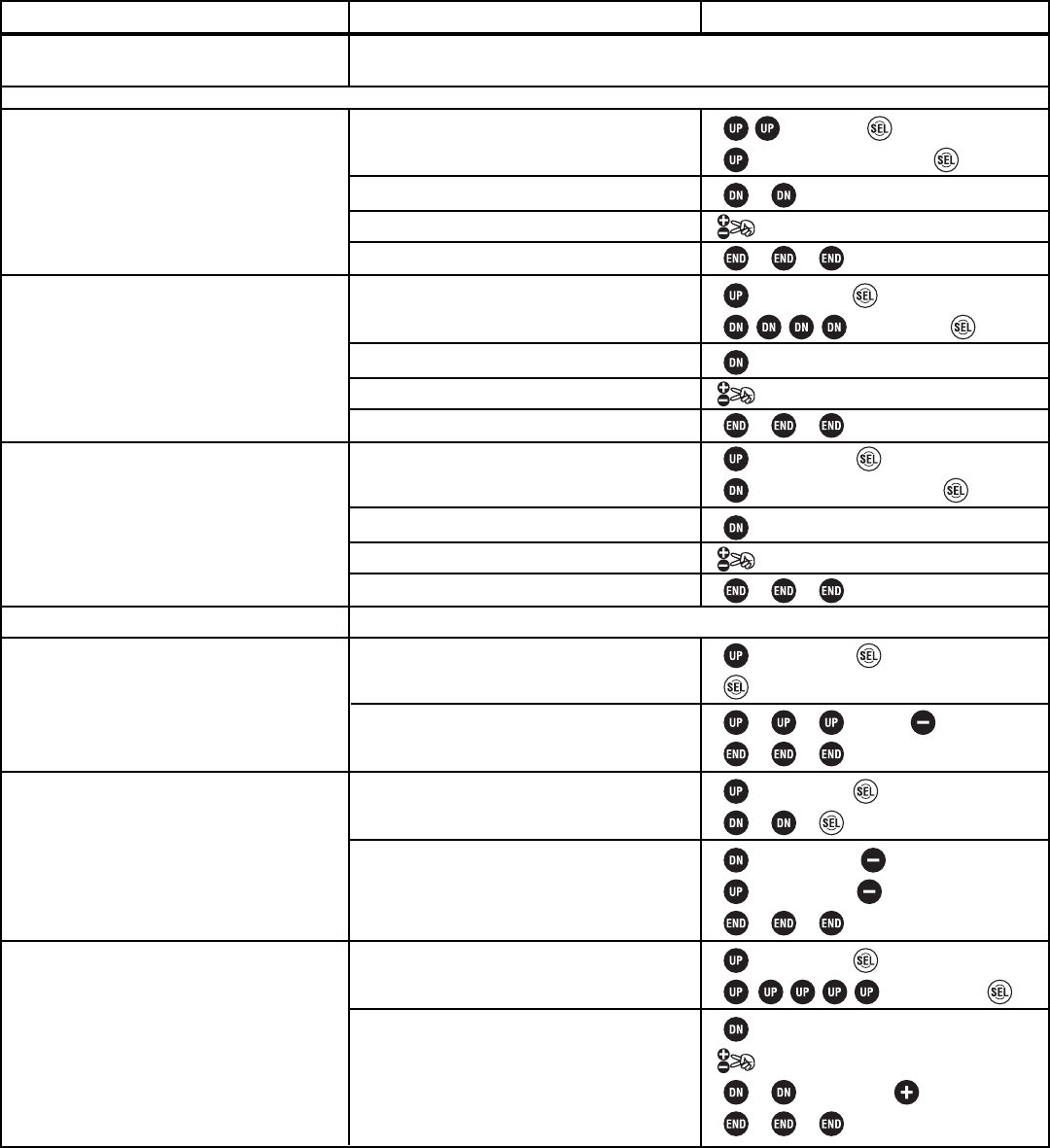
QUICK START GUIDE TO MOST COMMONLY USED FEATURES
HINT: The direct selection menu provides fast access to most frequently used functions. To access the direct menu, simply turn on the display and press DIR.
Then press the correct button for the function you want to use (see the onscreen map). The button with no number exits the direct selection menu.
NOTE: Features are stored in different locations between the 3 menu systems for easiest use with that level model. All quick start steps assume that you are
following these instructions sequentially. This quick start guide assumes you are starting from a totally blank model setting, and are in the highest-complexity
setting, LV 3, until changed within the guide. For more details on each function, see the page # referenced in each step.
Interested in exploring more of what the 3PK has to offer? Open the front cover for a directory of features,
or open this rear cover for quick set-up tips for nitro engines and when to use which feature!
This is not a toy. Always read all precautions and instructions prior to operating this electronic device.
QUICK START GUIDE:
Prepare your model.
Select a different model memory.
(Example: Change from model 1 to model 3.)
(See p. 14.)
Change menu level to match the
complexity needed for this model and
your comfort level with the radio’s
features. (Example: set to “new user”
level, LV1.) (See p. 12.)
Change modulation, if needed.
(Example: change from HRS to PCM for
use with R113iP receiver.) (See p. 16.)
Reverse any servos needed. (Example:
When right wheel is applied, wheels turn left.
Reverse steering servo.) (See p. 18.)
End point adjustment. (Example: Steering
servo is binding, moving farther to each side
than the linkage can move. Decrease steering
EPA to 90% on each side.) (See p. 18.)
Set up FailSafe (PCM/HRS only) (Example:
To shut off engine in event of lost signal.)
(See p. 17.)
Activate battery FailSafe (PCM/HRS only)
(Example: To take engine to idle if receiver
battery drops below a set point.)
(See p. 17.)
STEPS:
Open menu system, locate and select
MDL-SEL.
Select desired model.
Confirm the change.
Close menus.
Open menu system, locate and select
LEVEL-SEL.
Select desired level.
Confirm the change.
Close menus.
Open menu system, locate and select
MOD-MODE.
Select desired modulation.
Confirm the change.
Close menus. Turn Tx off/on to take effect.
Open menu system, locate and select CH-REV.
Select desired servo. Reverse that servo.
Close menus.
Open menu system, locate and select CH-EPA.
Select desired channel. Set EPA as
desired. Close menus.
Open menu system, locate and select
FAIL-SAFE.
Select channel to put to a preset position.
Activate battery failsafe response.
Close menus.
INPUTS for EXAMPLE:
to MENU 2. to select this menu.
6 steps to MDL-SEL. to open.
to M3.
to accept.
to MENU 3. to select this menu.
to LEVEL-SEL. to open.
to LV1.
to accept.
to MENU1. to select this menu.
6 steps to MOD-MODE.
to PCM.
to accept.
Transmitter off/on.
to MENU1. to select this menu.
to ST. to REV.
to MENU1. to select this menu.
to ST-RGHT. to 90%.
to ST-LEFT. to 90%
to MENU1. to select this menu.
to FailSafe
to TH. Hold trigger in desired position
to store.
to MODE. to ON.
Install all servos, switches, and receivers per your model’s instructions.
Charge transmitter and receiver batteries at least 18 hours prior to first use.
Test proper transmitter function. See Page 9.
Set up servo centers, linkages. Turn on receiver, center servos, hook up linkages.