Futaba FP-PK-FM-75B Radio Control Transmitter User Manual I
Futaba Corporation Radio Control Transmitter I
Futaba >
Contents
- 1. User Manual I
- 2. User Manual II
User Manual I

RR
Digital Proportional R/C System
1M23N11002

2
Thank you for purchasing the Futaba 3PK.
Prior to operating your 3PK, please read this manual thoroughly and use your
system in a safe manner.
After reading this manual store it in a safe place.
Application, Export and Reconstruction
1. Use this product in surface models only.
The product described in this manual is subject to regulations of the Ministry of
Radio/Telecommunications and is restricted under Japanese law to such pur-
poses.
2. Exportation Precautions
(a) When this product is exported from Japan, its use is to be approved by the
Radio Law of the country of the destination.
(b) Use of this product with other than models may be restricted by Export and
Trade Control Regulations. An application for export approval must be submit-
ted.
3. Modification, adjustment and replacement of parts.
Futaba is not responsible for unauthorized modification, adjustment and re-
placement of parts of this product.
THE FOLLOWING STATEMENT APPLIES TO THE
RECEIVER (FOR U.S.A.)
This device complies with part 15 of the FCC rules. Operation is subject to the
following two conditions.
(1) This devise may not cause harmful interference, and
(2) This devise must accept any interference received, including interference
that may cause undesired operation.
3
THE RBRCTM SEAL (FOR U.S.A.)
The RBRCTM SEAL on the (easily removable) nickel-cadmium battery con-
tained in Futaba products indicates that Futaba Corporation of America is vol-
untarily participating in an industry program to collect and recycle these batter-
ies at the end of their useful lives, when taken out of service within the United
States. The RBRCTM program provides a convenient alternative to placing used
nickel-cadmium batteries into the trash or municipal waste which is illegal in
some areas.
Futaba Corporation of America's payments to RBRCTM makes it easy for you to
return the spent battery to Futaba for recycling purposes. You may also contact
your local recycling center for information on where to return the spent battery.
Please call 1-800-8-BATTERY for information on Ni-Cd battery recycling in
your area. Futaba Corporation of America's involvement in this program is part
of its commitment to protecting our environment and conserving natural re-
sources.
RBRCTM is a trademark of the Rechargeable Battery Recycling
Corporation.
-No part of this manual may be reproduced in any form without prior permission.
-The contents of this manual are subject to change without prior notice.
-This manual has been carefully written, please write to Futaba if you feel that any corrections or clarifica-
tions should be made.
-Futaba is not responsible for the use of this product.

4
For Your Safety As Well As That Of Others .........
Explanation of Symbols ...................................................................................
High Response System (H.R.S) Precautions .................................................
Operation Precautions ....................................................................................
Nicad Battery Handling Precautions..............................................................
Storage and Disposal Precautions ................................................................
Other Precautions..........................................................................................
Table Of Contents
Before Using ............................................................
Features...........................................................................................................
Set Contents ...................................................................................................
Nomenclature.................................................................................................
Installation................................................................
Receiver and Servo Connections ..................................................................
Installation Safety Precautions .....................................................................
Initial Set-Up............................................................
Preparations (Transmitter) ..........................................................................
Functions ..................................................................
End Point Adjuster .........................................................................................
Steering EXP ..................................................................................................
Steering Speed................................................................................................
Throttle EXP ..................................................................................................
Throttle Speed ...............................................................................................
A.B.S. Function ...............................................................................................
Throttle Acceleration ....................................................................................
Start Function / Engine Cut ..........................................................................
Brake Mixing ...................................................................................................
Idle-Up .............................................................................................................
Timer ...............................................................................................................
Lap List ............................................................................................................
Programmable Mixing 1/2 .............................................................................
Boat Mode .......................................................................................................
Function Map ...........................................................
Menu Selection ...............................................................................................
Direct Selection..............................................................................................

5
Subtrim .................................................................................................
Channel Reverse ..................................................................................
Fail Safe/Battery Fail Safe (HRS/PCM Mode Only) ..........................
Model Select .........................................................................................
Model Reset ..........................................................................................
Model Copy...........................................................................................
Model Name .........................................................................................
Function Select Dial ............................................................................
Function Select Switch ........................................................................
Dual Rate/Second Dual Rate ..............................................................
ATL Function .......................................................................................
Channel 3 Position ...............................................................................
HRS/PCM/PPM Select .........................................................................
Level Select ..........................................................................................
System functions ..................................................................................
Direct Selection Button ......................................................................
Servo View............................................................................................
HRS ESC Set Up ..................................................................................
Adjuster ................................................................................................
For Your Safety
As Well As
That Of Others
Before
Using
Installation
Initial
Set-Up
Function
Map
Functions
Reference
Reference ........................................................
Ratings.................................................................................................
Optional Parts ....................................................................................
Troubleshooting.................................................................................
Error Displays.....................................................................................
When requesting repair ..............................................
Glossary ..............................................................................................
Glossary (LCD Display) .....................................................................
3PK Data Sheet......................................................................
6
For Your Safety As Well As That Of Others
For Your Safety As Well As That Of Others
Use this product in a safe manner. Please observe the following safety precautions at
all times.
Explanation of Symbols
The parts of this manual indicated by the following symbols are extremely important
and must be observed.
Danger
Indicates a procedure which could lead to a dangerous situ-
ation and may cause death or serious injury if ignored and
not performed properly.
Warning Indicates procedures which may lead to dangerous situa-
tions and could cause death or serious injury as well as su-
perficial injury and physical damage.
Caution Indicates procedures that may not cause serious injury, but
could lead to physical damage.
Symbols: ; Prohibited ; Mandatory
Symbols Explanation
In case of the High Response System (H.R.S) receiver R203HF, always use only the
following conditions:
Servo; 6V type Digital Servo only
Power supply; 6V Nicd battery
Transmitter setting; "HRS" mode
If the conditions are different, control is impossible.
And Fail Safe Unit (FSU1) is not available.
Caution
High Response System (H.R.S) Precautions
Mandatory Procedures
FCC Compliance Statements:
Any adjustment or modification to the device not expressly authorized by the party responsible for
compliance could result in a violation of the FCC Rules and void the users authority to operate the
equipment.
7
For Your Safety As Well As That Of Others
Operation Precautions
Warning
Prohibited Procedures
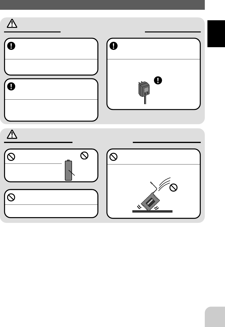
Do not operate two or more models
on the same frequency at the same
time.
Operating two or more models at same time on the
same frequency will cause interference and loss of
control of both models.
AM, FM (PPM) and PCM are different methods
of modulation. Nonetheless the same frequency
can not be used at the same point in time, regard-
less of the signal format.
Do not operate outdoors on rainy
days , run through puddles of water or
when visibility is limited.
Should any type of moisture (water or snow) enter any
compoent of the system, erratic opreation and loss of
control may occur.
Do not operate in the following
places.
-Near other sites where other radio control
activity may occur.
-Near people or roads.
-On any pond when rowboats are present.
-Near high tension power lines or communi-
cation broadcasting antennas.
Interference could cause loss of control . Improper in-
stallation of your Radio Control System in your model
could result in serious injury.
Do not operate this R/C system when
you are tired, not feeling well or under
the influence of alcohol or drugs.
Your judgment is impaired and could result in a dan-
gerous situation that may cause serious injury to
yourself as well as others.
Mandatory Procedures
Extend the transmit-
ter antenna to its full
length.
If the transmitter antenna is not
fully extended the operating
range of the radio will be re-
duced.
Check the transmitter antenna to be
sure it is not loose.
If the transmitter antenna works loose, or is discon-
nected while the model is running signal transmission
will be lost. This will cause you to lose control of the
model..
Always perform a operating range
check prior to use.
Problems with the radio control system as well as im-
proper installation in a model could cause loss of con-
trol.
(Simple range test method)
Have a friend hold the model, or clamp it down or
place it where the wheels or prop can not come in
contact with any object. Walk away and check to
see if the servos follow the movement of the con-
trols on the transmitter. Should you notice any ab-
normal operation, Do not operate the model. Also
check to be sure the model memory matches the
model in use.
8
For Your Safety As Well As That Of Others
Caution
Prohibited Procedures
Mandatory Procedures
Do not touch the engine, motor, speed control or any part of
the model that will generate heat while the model is operating
or immediately after its use.
These parts may be very hot and can cause serious burns.
Turning on the power switches.
Always check the throttle trigger on the
transmitter to be sure it is at the neutral
position.
1. Turn on the transmitter power switch.
2. Turn on the receiver or speed control
power switch.
Turning off the power switches
Always be sure the engine is not
running or the motor is stopped.
1. Turn off the receiver or speed control power switch.
2. Then turn off the transmitter power switch.
If the power switches are turned off in the opposite
order the model may unexpectedly run out of control
and cause a very dangerous situation.
When making adjustments to
the model do so with the en-
gine not running or the motor
disconnected.
You may unexpectedly lose control and
create a dangerous situation.
When operating your model
always display a frequency
flag on your transmitter an-
tenna.
When adjusting the transmitter on land while preparing to run (cruise), take measures
so that the wind will not knock over the transmitter.
If the transmitter is knocked over, the throttle stick may be accidentally set to the operating position and you may
lose control.
(Fail safe function) ---H.R.S or PCM mode only
Before running (cruising), check the fail safe function.
Check Method;
Before starting the engine, check the fail safe function as follows:
1) Turn on the transmitter and receiver power switches.
2) Wait at least one minute, then turn off the transmitter power switch. (The transmitter automatically transfers the fail
safe data to the receiver every minute.)
3) Check if the fail safe function moves the servos to the preset position when reception fails.
The fail safe function is a safety feature that minimizes set damage by moving the servos to a preset position when
reception fails. However, if set to a dangerous position, it has the opposite effect. When the reverse function was used
to change the operating direction of a servo, the fail safe function must be reset.
Setting example: Throttle idle or brake position
9
For Your Safety As Well As That Of Others
Nicad Battery Handling Precautions
(Only when Nicad batteries are used)
Warning
Mandatory Procedures
Always check to be sure your batter-
ies have been charged prior to oper-
ating the model.
Should the battery go dead while the model is operat-
ing loss of control will occur and create a very danger-
ous situation.
To recharge the transmitter Nicad ,
use the special charger made for this
purpose.
Overcharging could cause the Nicad battery to over-
heat, leak or explode. This may lead to fire, burns,
loss of sight and many other type's of injuries.
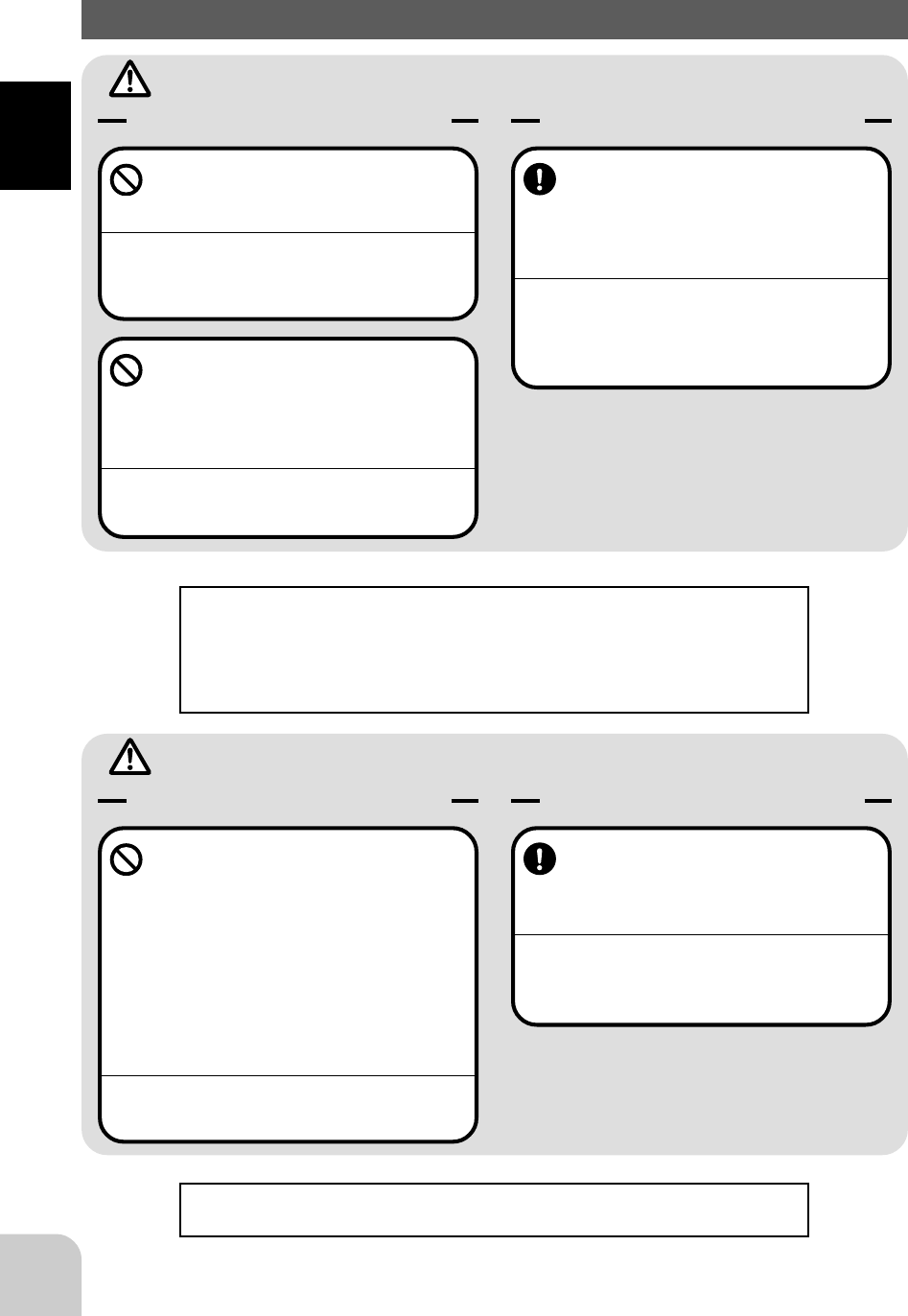
Caution Prohibited Items
Do not use commercial AA
size Nicad batteries.
Quick charging may cause the
battery contacts to overheat and
damage the battery holder.
Do not short circuit the Nicad battery
terminals.
Causing a short circuit across the battery terminals
may cause abnormal heating, fire and burns.
Do not drop the Nicad battery or ex-
pose it to strong shocks or vibrations.
The battery may short circuit and overheat, electrolyte
may leak out and cause burns or chemical damage.
When the model is not being used,
always remove or disconnect the
Nicad battery .
Should the battery be left connected this could create
a dangerous situation if someone accidentally turns
on the receiver power switch. Loss of control would
occur.
Special
Charger
Nicad AA size
batteries.
Use
prohibited
Shock
Prohibited
10
For Your Safety As Well As That Of Others
Storage and Disposal Precautions
Warning
Prohibited Procedures
Do not leave the radio system or
models within the reach of small chil-
dren.
A small child may accidentally operate the system,
this could cause a dangerous situation and injuries.
Nicad batteries can be very dangerous when mis-
handled and cause chemical damage.
Do not throw Nicad batteries into a
fire. Do not expose Nicad batteries to
extreme heat. Also do not disas-
semble or modify a Nicad battery
pack.
Overheating and breakage will cause the electrolyte
to leak from the cells and cause skin burns, loss of
sight as well as other injuries.
Mandatory Procedures
When the system will not be used for
any length of time store the system
with batteries in a discharged state.
Be sure to recharge the batteries prior
to the next time the system is used.
If the batteries are repeatedly recharged in a slightly
discharged state the memory effect of the nicad bat-
tery may considerably reduce the capacity . A reduc-
tion in operating time will occur even when the batter-
ies are charged for the recommended time.
<Nicad Battery Electrolyte>
The electrolyte in Nicad batteries is a strong alkali. Should you get even the
smallest amount of the electrolyte in your eyes, DO NOT RUB, wash immedi-
ately with water, seek medical attention at once. The electrolyte can cause blind-
ness. If electrolyte comes in contact with your skin or clothes, wash with water
immediately.
Caution
Prohibited Procedures
Do not store your R/C system in the
following places.
- Where it is extremely hot or cold.
- Where the system will be exposed to direct
sunlight.
- Where the humidity is high.
-Where vibration is prevalent.
-Where dust is prevalent.
-Where the system would be exposed to
steam and condensation.
Storing your R/C system under adverse conditions
could cause deformation and numerous problems
with opreation.
Mandatory Procedure
If the system will not be used for a
long period of time remove the batter-
ies from the transmitter and model
and store in a cool dry place.
If the batteries are left in the transmitter electrolyte
may leak and damage the transmitter. This applies to
the model also, remove the batteries from it also to
prevent damage.
<Nicad Battery Recycling>
A used Nicad battery is valuable resource. Insulate the battery terminals and
dispose the battery by taking it to a battery recycling center.

11
For Your Safety As Well As That Of Others
Other Precautions
Caution
Prohibited Procedures
Do not expose plastic parts to fuel,
motor spray, waste oil or exhaust.
The fuel, motor spray, waste oil and exhaust will pen-
etrate and damage the plastic.
Always use only genuine Futaba
transmitters, receivers, servos, FET
amps (electronic speed
controls),Nicad batteries and other
optional accessories.
Futaba will not be responsible for problems caused by
the use of other than Futaba genuine parts. Use the
parts specified in the instruction manual and catalog.
Mandatory Procedures

12
Before Using
- High Response System (H.R.S. system)
When used with the H.R.S. system, a speed of triple that of an FM system at average
response is realized. (Comparison with other Futaba products) The T3PK transmitter
is
compatible with the H.R.S. system, PCM1024 system, and PPM (FM) system.
- 128x64 dot large graphic LCD/with backlighting
EXP curve, throttle curve, servo view, and other graph display and function selection
can batch display simple menus and function setup items, and data setup is easy.
Backlighting that can be turned ON/OFF also improves recognition at indoor cir-
cuits,
etc.
- 10 models memory/+ 10 models by using a data pack
Model names can use up to 10 letters, numbers, and symbols so that easily under-
stood
names can be set. Model copy function simplifies creation of a model memory with
different fine setups. An additional 10 models memory can be added by using the
optional data pack (DP-16K).
- Two function selection modes: Menu selection and direct call
Setup screens are called from a menu screen. The menu screen can be selected from
among 3 levels (LV1/LV2/LV3) to match the level of use.
Frequently used (high urgency) functions can be quickly called by assigning them to
direct call buttons. (6 functions)
- Brake mixing for large cars (BRAKE-MIX)
Brake mixing of the front and rear wheels of 1/5GP cars, etc. has delay and balance
adjustment functions.
- Second dual rate (2ND D/R)
Steering angle can be switched with one touch while running.
- Anti-skid Braking System (A.B.S.)
This function applies the brakes so that the tires of gasoline engine cars, etc. do not
their grip on the road even when braking at corners.
- Throttle acceleration (TH-ACCEL)
Gasoline engine cars have a time lag before the clutch and brakes are connected. The
TH-ACCEL function minimizes this time lag.
- Throttle speed (TH-SPEED)
Sudden trigger operation on slippery roads only spins the wheels unreasonably and
does not accelerate smoothly. Setup the throttle speed function allows smooth and
enjoyable operation while at the same time reducing battery consumption.
Before Using
Features

13
Before Using
- Start function (AT-START)
When the throttle trigger is set to full throttle simultaneously with starting on slippery
roads, the wheels spin and the vehicle does not accelerate (start). Setup the start
function allows smooth starting.
- Steering speed (ST-SPEED)
"When you sense that the steering servo is too fast, etc., the servo operating speed
(direction that suppresses the maximum speed) can be adjusted.
- Racing timer (TIMER)
A lap timer can record 99 lap times and the total time. The timer can also be started
automatically by trigger operation. The race time and an audible alarm can be set. A
navigation timer effective during training runs is provided. Target lap and refueling
time can be indicated by audible alarm. Other timers are an up timer and a down
timer.
- Digital trim w/reset function
The trim position is constantly displayed on an LCD screen. The operation amount of
1
step can also be adjusted. Steering and throttle trim operations have no on the
maximum steering position.
- Function select dial function (FUNC-DIAL)
This function assigns a function to dials (digital trim, grip dial, knob). The step size
and operating direction can also be adjusted. Trim positioning at each model call is
unnecessary because all the dials are digital.
- Function select switch function (FUNC-SW)
This function assigns a function to the three installed switches. The operating direc-
tion
can also be set.
- Wheel position can be changed.
The wheel position can be changed by using the offset adapter (supplied). The angle
can also be adjusted.
- Adaptable for left-handed operators
The wheel section left and right mounting direction can be reversed.
- Black antenna
- NEW design considers operability and weight balance.
- Tension adjustment function
The wheel tension can be adjusted from the outside.
- Trigger stopper function (Mechanical ATL)
- Display switch
Functions can be set without emitting radio waves.
- Receiver w/DSC is standard equipment (Connection cord is option.)
HRS system: R203HF, PCMN type: R113iP
- 7-color LED pilot lamp
You can select your favorite color.
14
Before Using
Set Contents
After opening the box, first check if the contents conform to the following. The con-
tents depend on the set as shown below.
- If any of the set contents are missing, or you have any questions, please contact you
dealer.
Transmitter T3PK
RF module PK-FM
Receiver R203HF(HRS-FM) or R113iP(PCM)
Servo
Miscellaneous
Transmitter Ni-cad battery pack NT8F700B
or Battery box
*Installed in transmitter.
Receiver switch
Wheel position offset adapter(A.P.A.)
Instruction manual
*Installed in transmitter.
Always use only genuine Futaba transmitter, receiver, FET amp, Ni-cad battery and
other optional parts.
Futaba will not be responsible for damage caused by other than genuine Futaba parts and components. Use only
the genuine Futaba parts and components listed in the instruction manual and catalog.
Caution
In case of the High Response System (H.R.S) receiver R203HF, always use only the
following conditions:
Servo; 6V type Digital Servo only
Power supply; 6V Nicd battery
Transmitter setting; "HRS" mode
If the conditions are different, control is impossible.
And Fail Safe Unit (FSU1) is not available.
Caution
15
Before Using
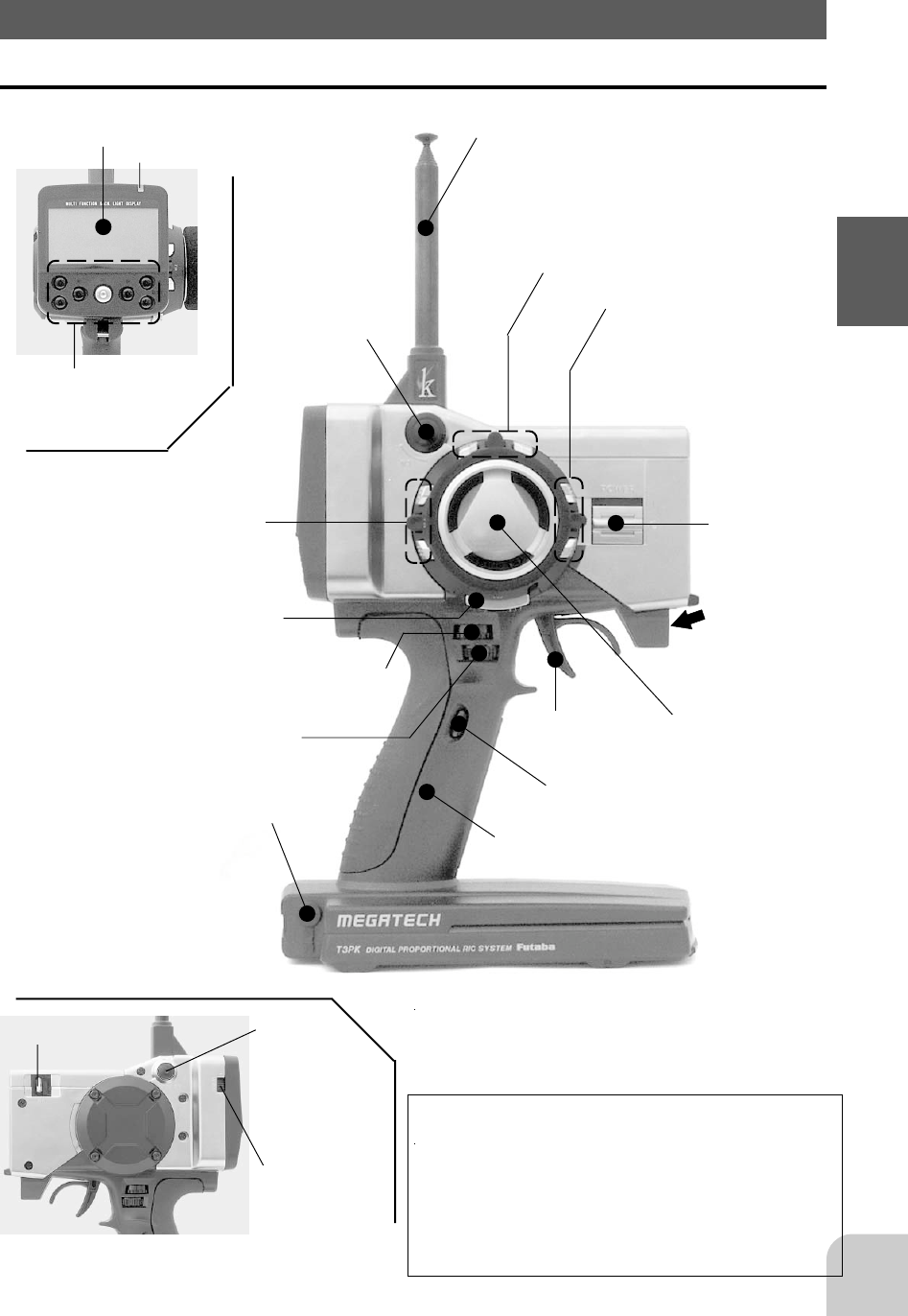
Transmitter T3PK
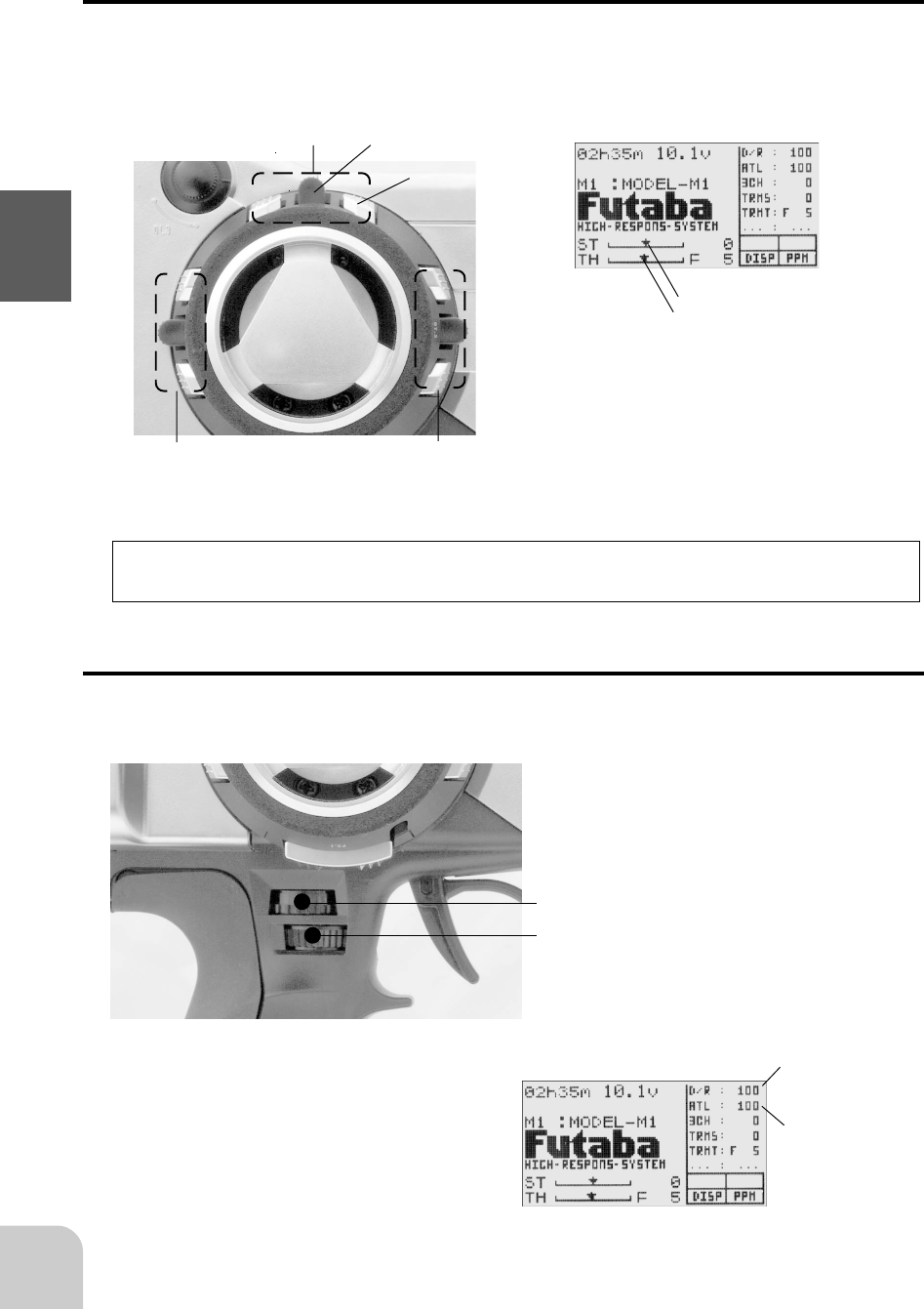
Nomenclature
Antenna
Throttle trim
(DT2)
Edit buttons
Steering wheel
Steering trim (DT1)
LCD screen
Push switch 1 (PS1)
Power
switch
Digital trim 3 (DT3)
Pilot lamp
CH3 knob
( DL3)
Mechanical ATL
adjusting screw
Throttle
trigger
(See page 16 for the operating
instructions.)
(See page 16 for the operating instructions.)
(See page 17 for the
adjustment instructions.)
(See page 16 for the operating
instructions.)
Grip Handle
Push
switch 3
(PS3)
Crystal
Display
switch
Steering dual rate dial (DL1)
(See page 16 for the operating instructions.)
Push switch 2 (PS2)
ATL dial (DL2)
(See page 16 for the operating instructions.)
*The switches, knobs, and trimmers in the
figure are shown in the initial setting position.
Precautions when turning the power
switch on and off.
When the data was changed using the edit
keys or trim levers, wait at least two seconds
before turning off the power. If the power is
turned off within two seconds after the data
was changed, the new data will not be written
to memory.
Sound port
- Use a commercial earphone.
(Use a radio earphone with a 3.5mm di-
ameter plug.)
- When the surroundings are noisy during
races, etc., you can listen to the alarm
tone using an earphone. The alarm tone
can also be heard from the transmitter.
16
Before Using
Digital Trim Operation
(Initial settings: DT1: Steering trim, DT2: Throttle trim, DT3: -------)
Operating by the lever: Push the lever to the left or right (up or down).
Operating by push button switch: Press the push button switch in the desired direc-
tion. The current position is displayed on the LCD screen.
Steering trim display
Throttle trim display
- Each step is indicated by a tone.
- When the trim exceeds the maximum trim adjustment
range, the tone will change pitch and the lever will not
move any farther.
- Return to the neutral position (center) by pressing both
the push button switches simultaneously for about one
second.
Trim Operation
With the center trim feature, trim adjustments have no effect on the maximum servo
travel. This prevents the linkages from binding when adjustments are made.
DT2
DT1 Lever
Push button switch
DT3
Grip dial operation
(Initial settings: DL1=Steering D/R, DL2=ATL)
Operate the dials by turning them. The current set value is displayed on the LCD
screen.
DL1
DL2
- A click sound is made at each step.
- When the maximum position is reached at each side,
the tone of the click changes. Thereafter, the set value
does not change.
ATL display
Steering D/R display
17
Before Using
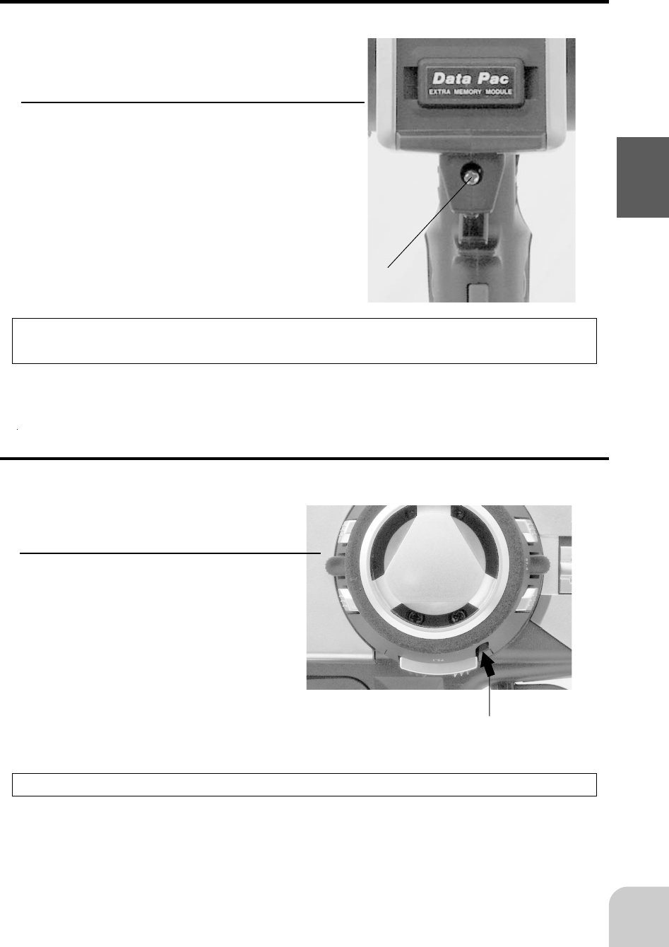
Mechanical ATL Adjustment
Adjustment
Using a Phillips screwdriver, adjust the
trigger brake (back) side stroke by turning
the screw through the adjusting hole indi-
cated by the arrow in the figure. (The
screw moves the throttle trigger stopper.)
- When the adjusting screw is turned clockwise, the
stroke becomes narrower.
Make this adjustment when you want to make the throttle trigger brake (back) side
stroke narrower.
Mechanical ATL
adjusting screw
Caution
When the stroke was adjusted, the throttle servo travel must be adjusted by data set-
ting.
Wheel Tension Adjustment
Make this adjustment when you want to change the steering wheel spring tension.
Adjustment
Turn the screw inside the adjusting
hole using a 1.5mm hex wrench.
Caution
If turned too far counterclockwise, the adjusting screw may fall out.
Tension adjusting
screw
- Turning the adjusting screw
clockwise, increases the spring
tension.
18
Before Using
For Ni-cad battery system
The Ni-cad battery is connected by a connector so that it can be removed when you
will not be using the transmitter for a long time, or when replacing a dead battery with
a spare battery.
- Always use an NT8F700B Ni-cad battery.
For dry cell battery system
Load the eight batteries in accordance with the polarity markings on the battery
holder.
-Dry cell battery (x8)
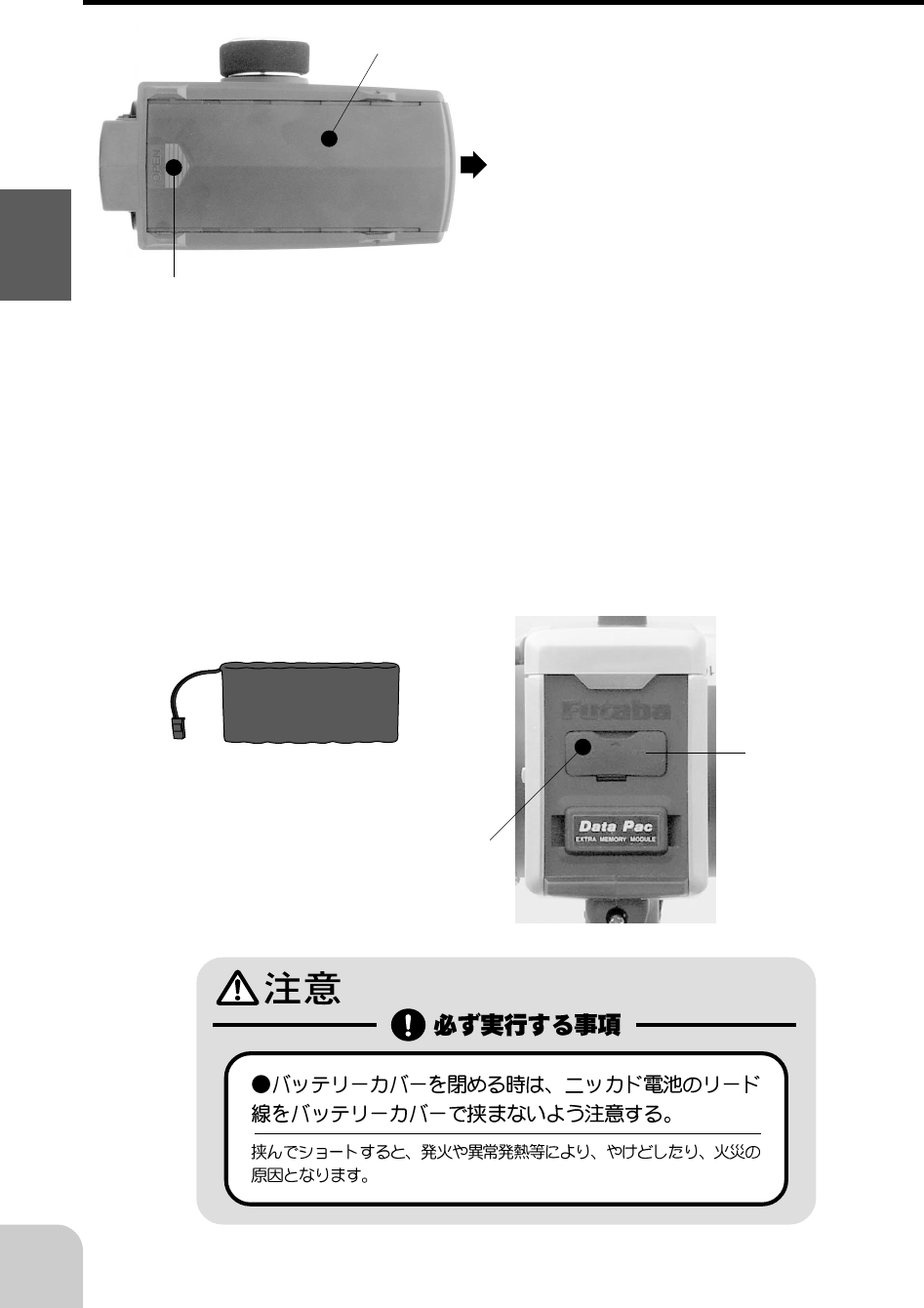
Battery Replacement
Battery cover
While pressing this part.
1. Slide the transmitter battery
cover in the arrow direction while
pressing the part shown in the
figure.
2. Replace the Ni-cad battery pack
or Dry cell batteries.
3. Slide the battery cover back onto
the transmitter.
Charging jack
(Interior)
Cover
Ni-cad battery
NT8F700B
19
Before Using
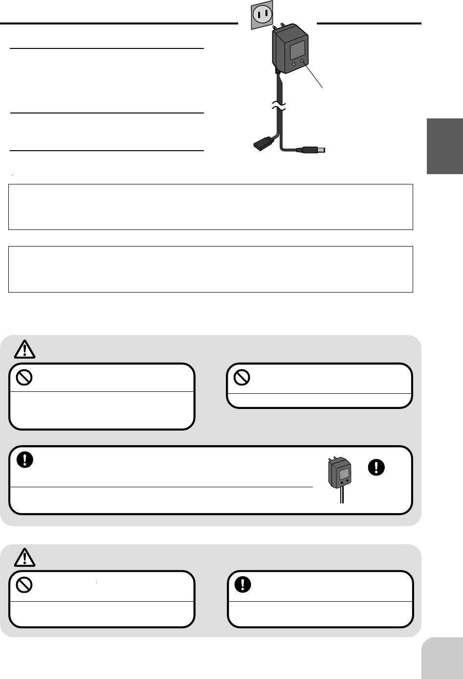
Charging the Ni-cad Battery
Charging
1. Plug the transmitter cord of the
special charger into the charg-
ing jack on the rear of the trans-
mitter.
2. Plug the charger into an AC out-
let.
3. Check that the charging LED
lights.
Charger
Transmitter charging
LED
Cord to transmit-
ter charging jack
When charging the NT8F700B Ni-cad battery with the special charger, allow about
15 hours for charging. If the transmitter has not been used for some time, cycle the
battery by charging and discharging it two or three times.
Over current protection
The transmitter charging circuit is equipped with an over current protection circuits
(1.5A). If the battery is charged with a quick charger for other than digital propor-
tional R/C sets, it may not be fully charged.
Always use the special charger or a quick charger for digital pro-
portional R/C sets to charge a digital proportional R/C set Ni-cad
battery.
Overcharging a Ni-cad battery can result in burns, fire, injuries, or loss of sight due to
overheating, breakage, or electrolyte leakage.
Never try to recharge a dry cell bat-
tery.
The transmitter may be damaged or the battery
electrolyte may leak or the battery may break.
When the charger is not in use, dis-
connect it from the AC outlet.
Do this to prevent accidents and to avoid overheat-
ing.
Caution
Never plug it into an outlet other
than indicated voltage.
Plugging the charger into the wrong outlet may re-
sult in an explosion, sparking, or fire.
Do not insert and remove the
charger when you hands are wet.
It may cause an electric shock.
Warning
Use the
special
char
g
er.
AC outlet
20
Before Using
Handling the RF module
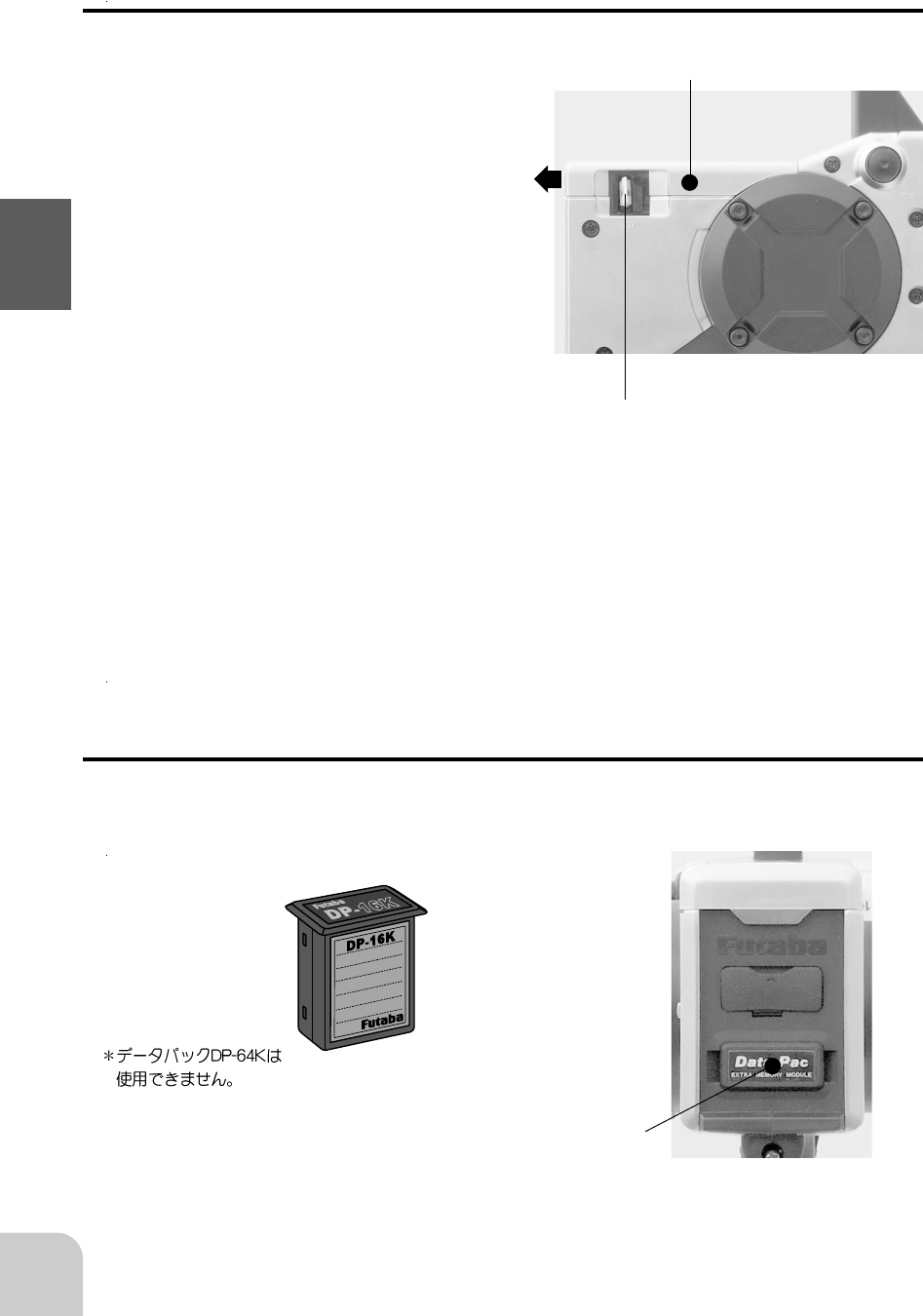
Removing the RF module
1 Remove the RF module cover by slid-
ing it in the arrow direction.
2.Pull the module upward while pushing
the left and right claws to the inside.
Inserting the RD module
1 Insert the module while being careful
that the transmitter side connector
pins are not bent.
2 Push in until the claws lock with a
"click".
3 Install the RF module cover by sliding
it.
- Crystal can be changed without removing the
RF module.
- See page for the crystals that can be used.
RF module temperature rise
When the transmitter is in use, the RF module temperature will rise slightly. This is
normal.
Handling the data pack
With the 3PK transmitter, the setup data of 10 models can be stored in the transmitter
itself and the setup data of 10- models can be stored in a DP-16 removable data pack
(Option).
DP-16K data
pack (Option)
RF module cover
Data pack insertion hole
- Hold the dust cap and insert the data
pack in all the way.
21
Before Using
MEMORY MODULE
INITIALIZE ?
YES > +
NO > -
ON
OFF
When inserting and removing the data pack
Always turn off the transmitter power before removing or inserting the data pack.
Data pack initialization
When using the data pack, initialization is necessary so
that the data pack can be used with this transmitter. When
"INITIALIZE?" is displayed on the screen at power ON,
press the (+) button. This automatically initializes the data
pack. No further action is necessary.
When a data pack used with another model has been inserted, and initialization is
executed by pressing the (+) button when "INITIALIZE?" is displayed on the screen
at power ON, the old data is destroyed so the data pack can be used with the 3PK.
Data interchangeability with other models
Data is not interchangeable with 3PJsuper, 3VC, and other transmitters other than the
3PK.
Set data backup
The set data of each function (transmitter body and data pack) of the 3PK transmitter
is stored in a memory element that does not require a backup battery. Therefore, the
3PK transmitter can be used without paying attention to the backup battery life.
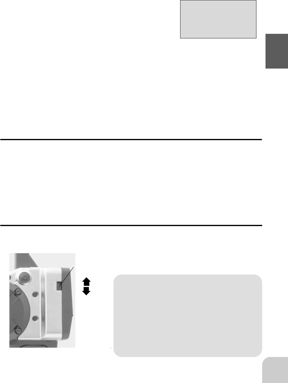
Display switch
If the display switch is turned on without turning on the power switch, transmitter
side data setup is possible without emitting radio waves.
Display switch
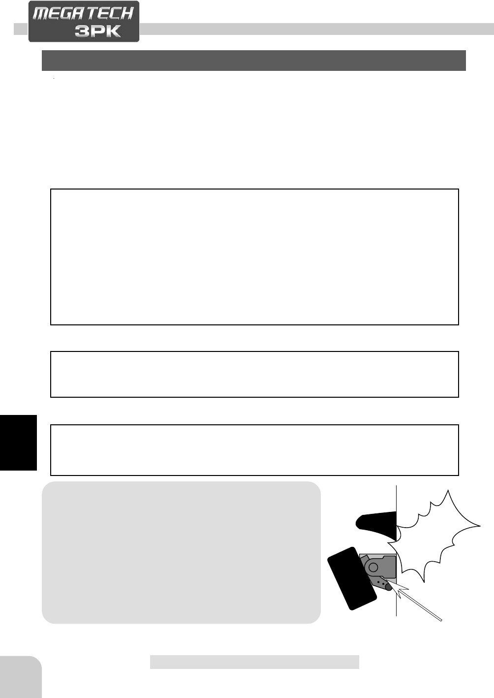
WARNING
( ) Prohibited item
Never turn on the power switch while this
function is in use.
If the power switch is turned on, radio waves
will be emitted and interfere with
vehicles (boats) operating on the same band
(frequency) and is very dangerous.
22
Before Using
DL1
DL2
DL3
DT1
DT2
DT3
* Function names and rate
assigned to dials are dis-
played.
* Displays whether or not a data
pack is inserted. When a data pack
is inserted, "DPAC" is displayed.
* "BLHT" is displayed when back-
lighting is ON.
* When radio waves are being emit-
ted, "RF" is displayed. When radio
waves are
not being emitted when turned on by
display switch and when the DSC
function is used, "DISP" is dis-
played.
* The current operation mode is dis-
played. ("PPM"/"PCM"/"HRS")
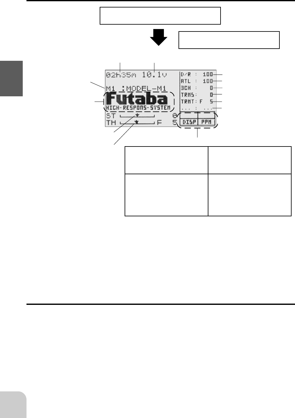
Display when power switch turned on
Power switch turned on
Beep confirmation sound is generated and
the initial screen shown below appears.
Total timer display (H:M)
Battery voltage display
Model name (10 characters)
* Display mode can be changed
by using the SYSTEM function.
(Page )
Steering trim display
Throttle trim display
User name display
When the (END) button is held down for 1 second or longer at the initial screen, the
Futaba logo and user name are displayed for about 2 seconds.
Total timer
The total timer shows the accumulated time from last reset.
The total time does not change even when the model changes.
Reset method
1 In the initial screen state, hold down the (+) and (-) buttons simultaneously
for 1 second.
* The total timer display counts up from 1 minute to 99hours 59 minutes.
23
Before Using
LCD Screen Contrast
The LCD screen contrast can be adjusted. (For more information, see page .)
Caution
Do not adjust the contrast so that the LCD is too bright or too dark.
When the display cannot be read due to a temperature change, data cannot be set.
LCD Screen Temperature Change
In the following cases, the LCD may become difficult to read due to a temperature
change.
- On hot summer days and cold winter days, the LCD may be easy to read indoors, but difficult to
read outdoors.
- If the contrast is too bright or too dark, temperature changes and lighting conditions may cause the
screen to become difficult to read.
Contrast adjustment when not called
1 Turn on the transmitter power again.
2 When the screen is too dark or too bright, adjust to a suitable contrast by pressing
the (-) or (+) button, respectively, while pressing the (SEL) button.
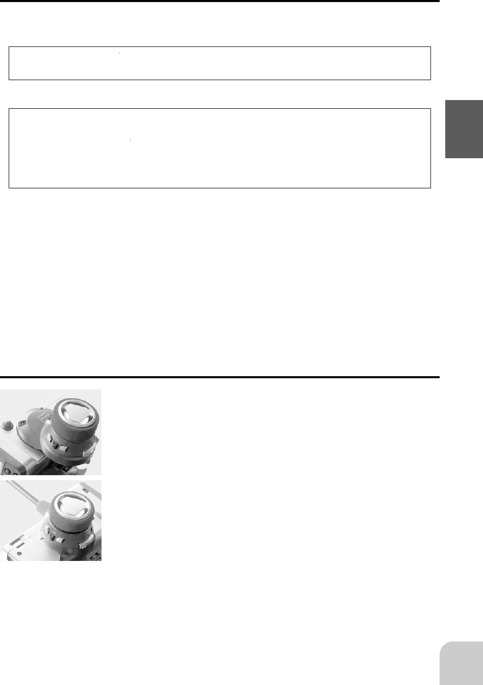
Changing wheel position/modifying for left-hand use
- Changing the wheel position
The wheel position can be offset by using the accessory offset
adapter. The wheel angle can also be adjusted.
- Modification for left-hand use
The wheel section left and right mounting direction can be re-
versed.
24
Before Using
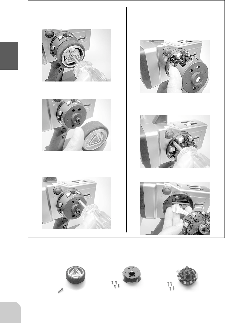
Removing the steering wheel unit
1. After removing the wheel cap,
carefully remove the screw
holding the steering wheel.
2. Remove the steering wheel.
3. Remove the 4 screws from
the wheel unit cover.
4. Remove the wheel unit cover.
Be very careful the wheel
shaft will fall out.
5. Remove the 4 screws from
the wheel unit.
6. Disconnect the wheel unit
connector.
Steering Wheel
Wheel Unit
Cover Wheel Unit
screw (large)
x1
screw (small)
x4
screw (middle)
x4
25
Before Using
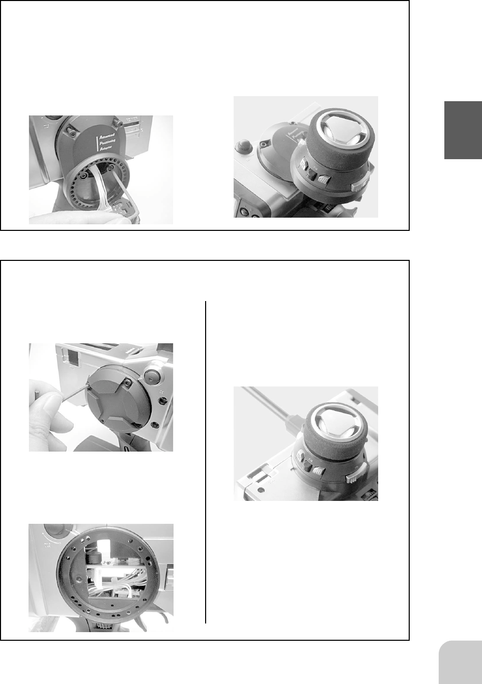
Changing wheel position
Modifying for left-hand use
1. Connect the wheel unit con-
nector through the offset
adapter. Install the adapter
using four 2.5mm hex bolts at-
tached.
2. Reinstall the wheel unit,
wheel unit cover, wheel, and
wheel cap in same position
as they were removed.
1. Remove the wheel back cover
using 2.5mm hex wrench.
2. Push the wheel unit connector
in the opposite side.
3. In opposite side, connect the
wheel unit connector and rein-
stall the wheel unit, wheel unit
cover, wheel, and wheel cap
in same position as they were
removed.
26
Before Using
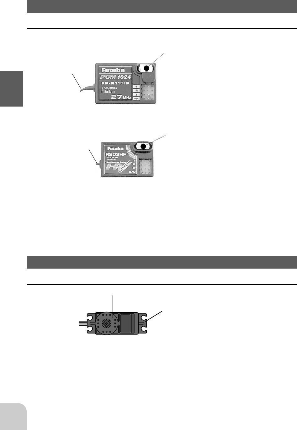
Receiver
Nomenclature
Crystal
When changing the frequency, use the
specified Futaba crystal set.
Antenna
Connectors
1: Steering servo (CH1)
2: Throttle servo (CH2)
3: CH3 servo (CH3)
B/C: Power connector/DSC connector
R113iP
receiver
For the receiver, servos, and other connections, see page 27. For the DSC cord (op-
tion) connections, see page 103.
to Receiver
Servo horn
Mounting flange
<Accessory>
The following items are provided for setting:
- Spare servo horn
- Parts for servo installation
(For the installation precautions, see page 28.)
Crystal
When changing the frequency, use the
specified Futaba crystal set.
Antenna
Connectors
1: Steering servo (CH1)
2: Throttle servo (CH2)
3: CH3 servo (CH3)
B/C: Power connector/DSC connector
R203HF
receiver
Servo
Nomenclature
27
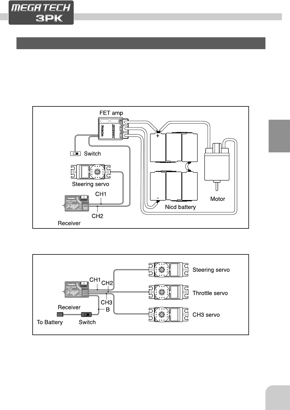
Installation
Installation
Receiver and Servo Connections
Installation When An FET Amp Is Used (MC800CFET Amp)
When connecting and installing the receiver and servos, read the “Installation Safety
Precautions” on the next page.
Installation For Gas Powered Models
28
Installation
Installation Safety Precautions
Warning
Connector Connections
Be sure the receiver, servo, crystal
and connectors are fully and firmly
connected.
If vibration from the model cause a connector to work
loose while the model is in operation. You may lose
control .
Electronic speed control
Install the heat sinks where they will
not come in contact with aluminum,
carbon fiber or other parts that con-
duct electricity.
If the FET Amp (Electronic speed control) heat sinks
touch other materials that conduct electricity a short
circuit could occur. This could result in loss of control
and damage to the system.
Receiver Vibration Damping and
Waterproofing
(Car)
Dampen the vibration to the receiver
by mounting to the chassis or mount-
ing plate with thick double sided tape
in electric powered models. In gas
powered models wrap the receiver in
foam and mount it where the vibration
is the least prevalent.
(Boat)
Dampen the vibration to the receiver
by wrapping it in foam. Waterproof by
placing it in plastic bag or watertight
radio box in model.
If the receiver is subjected to strong vibration or shock
erratic or loss of control may occur. If any moisture
comes in contact the receiver and servos you may
expertise the same result as well as damage to the
system.
Receiver Antenna
Do not cut or bundle the receiver an-
tenna
Do not bundle the receiver antenna
together with the servo lead wires
Keep the receiver antenna at least 1
inch away from the motor and battery
and wires that handle heavy current
loads..
Cutting, bundling or routing the receiver antenna near
any devise that produce noise will reduce the operat-
ing range of the system and result in loss of control.
*Also route the receiver antenna away from metal,
carbon fiber and other parts that conduct electric-
ity. These parts can transmit high frequency noise.
Servo Throw
Operate each servo over its full stroke
and be sure the linkage does not bind
or is loose.
The continuous application of unreasonable force to a
servo may cause damage and excessive battery
drain.
Servo Installation
When you install the servos always
use the rubber grommets provided in
servo hardware bags. Mount the ser-
vos so they do not directly come in
contact with the mount.
If the servo case comes in direct contact with the
mount vibration will be directly transmitted to the
servo.
If this condition continues for a long time the servo
may be damaged and control will be lost.
Motor Noise Suppression
Always install capacitors to suppress
noise when electric motors are used.
If capacitors are not properly installed you could ex-
perience erratic operation and reduced range as well
as loss of control.
Other Noise Suppression Methods
Be sure there are no metal parts in
your model which under vibration can
come in contact with other metal
parts.
Metal to metal contacts under vibration will omit a high
frequency noise that will effect the receivers perfor-
mance. You could experience erratic operation and
reduced range as well as loss of control.
29
Initial Set-Up
Initial Set-Up
Preparations (Transmitter)
Before setting the transmitter functions, check and set items 1 to 3 below.
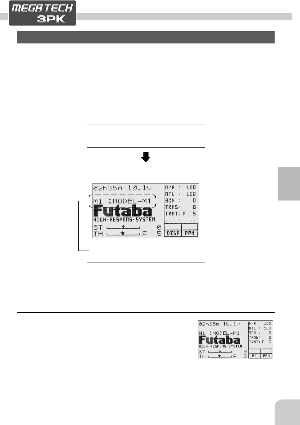
(Display when power switch turned on)
When the power switch is turned on, the currently selected model number is dis-
played. Check if this number is the model number you want to set-up. To change the
model number, use the Model Select function (page ).
Turn on the transmitter power.
1. RF Output Check
If signals are output normally, RF output monitor "RF"
will be displayed on the screen.
If RF is not displayed, check if the transmitter crystal and
RF module are installed.
If the transmitter is abnormal or faulty, contact your
Futaba dealer.
The model number is displayed.
(Start screen)
"RF"
30
Initial Set-Up
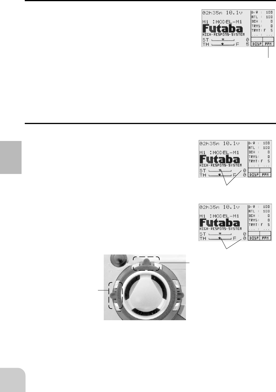
2. Modulation Mode Check
The T3PK transmitter output signal format can be
changed to match the type of receiver. Check if the
modulation mode is set to match the receiver used.
When using an FM receiver (e.g., R133F), the modula-
tion mode must be set to PPM. When using a PCM re-
ceiver (e.g., R113iP), the modulation mode must be set
to PCM. When using a H.R.S receiver (e.g., R203HF),
the modulation mode must be set to HRS. If this setting
is incorrect, change it with the HRS/PCM/PPM Select
(page ) function.
(PPM)
3. Trims Initial Set-Up
- Steering trim (DT1) check
At initial set-up, steering trim is assigned to digital trim
DT1 above the steering wheel. Operate the DT1 lever
and check if the steering trim display on the screen
changes. After checking the trim, set the trim display to
the center (N) position.
- Throttle trim (DT2) check
At initial set-up, throttle trim is assigned to digital trim
DT2 at the left side of the steering wheel. Operate the
DT2 lever and check if the throttle trim display on the
screen changes. After checking the trim, set the trim
display to the center (N) position.
31
Initial Set-Up
(Set-Up Procedure When Installed In a Car)
When installing the servos in a car, performing function set-up in the following order
is recommended.
1. Perform step 3. Trims Initial Set-Up of Preparations on the
preceding page.
2. Set the servo direction of operation using the Reverse
function. (Page )
The servo installation method and linkage direction depends
on the kit. Therefore, the servo operation direction may have
to be reversed relative to transmitter operation. Before in-
stalling the servo, check the operating direction and set it us-
ing the Reverse function.
3. Set the subtrim and adjust the servo neutral point. (Page )
4. Set the trigger travel by adjusting the throttle trigger me-
chanical ATL to you liking. (Page )
5. Set EPA of each channel and adjust the servo throw
(travel). (Pages )
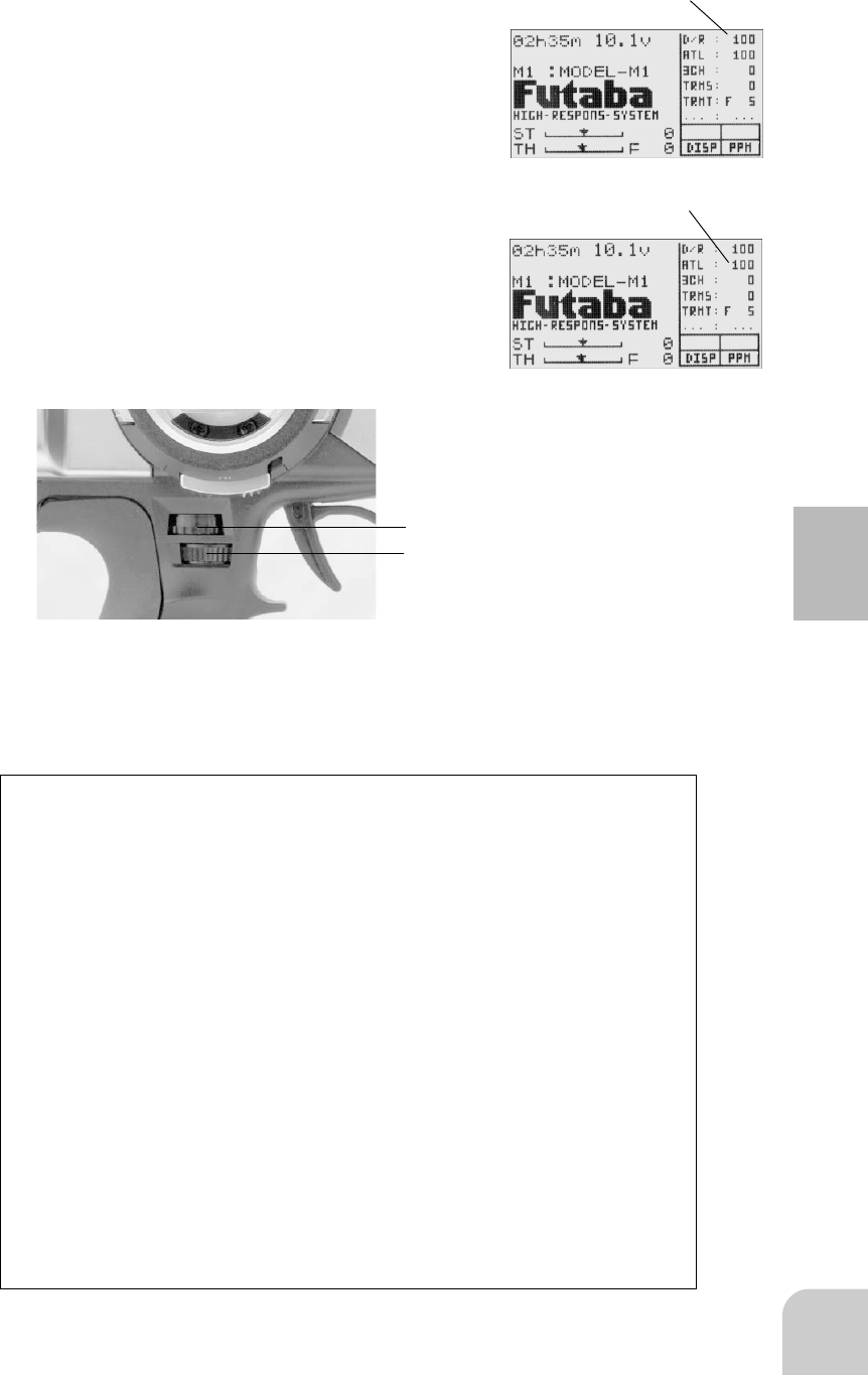
- Steering dual rate (DL1) check
At initial set-up, steering dual rate is assigned to grip
dial DL1 (upper) at the grip of the transmitter. Operate
the DL1 dial and check if the D/R value displayed on
the screen changes. After checking D/R, set the steer-
ing dual rate to 100%.
- Throttle ATL (DL2) check
At initial setting, throttle ATL is assigned to grip dial
DL2 (lower) at the grip of the transmitter. Operate the
DL2 dial and check if the ATL value displayed on the
screen changes. After checking ATL, set throttle ATL
to 100%.
32
Function Map
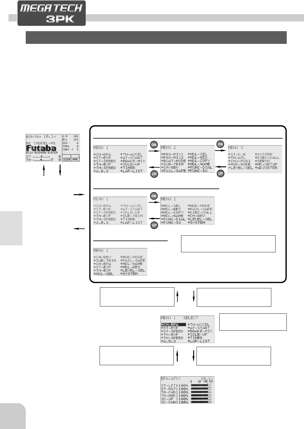
In case of the LV3
Function Menu Screen
Function Map
Menu Selection
The function set-up screen can be easily selected from the function menu displayed
on the LCD screen.
The function menu can be selected from among the following 3 levels to match the
level of use. To select the level, use the Level Select function (page ).
-Level 3 (LV3): All functions can be selected. (For expert driver)
-Level 2 (LV2): For middle class driver
-Level 1 (LV1): Basic functions only
(Start Screen)
In case of the LV2
In case of the LV1
(Function Select Screen)
(Function Set-up Screen)
33
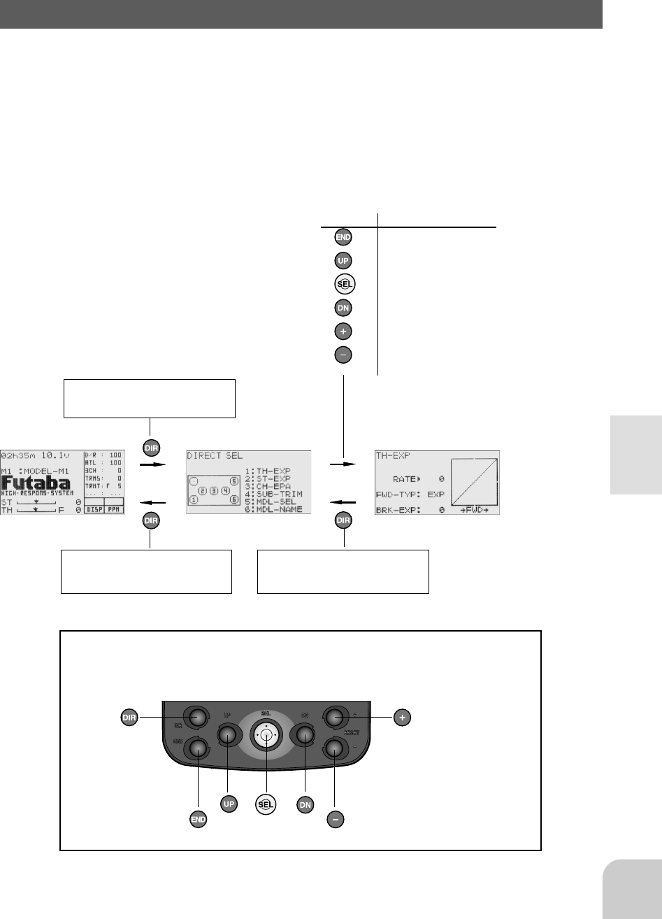
Function Map
INITIAL SETTING
Function
1. TH-EXP
2. ST-EXP
3. CHEPA
4. SUB-TRIM
5. MDL-SEL
6. MDL-NAME
The Direct Selection allows instant access to the six functions most frequently used.
The function set-up screen can be directly and quickly called with the special buttons
for each function of the six functions, they can be freely selected as the Direct Selec-
tion Button function.
Direct Selection
(Start Screen) ( Direct Selection Screen) (Function Set-up Screen)
34
Functions
Functions
End point adjuster/EPA (All channels)
Use this when performing steering left and right steering angle adjustments, throttle
high side/brake side operation amount adjustment, and channel 3 servo up side/down
side operation amount adjustment during linkage.
- Corrects the maximum steering angle and left and right steering angles when there
is a difference in the turning radius due to the characteristics, etc. of the vehicle.
Maximum steering angle
The EPA function basically determines the maximum steering angle of each channel.
The functions shown below may have been adjusted or the operating range set by
EPA function may be exceeded. Check the linkage each time the following functions
are adjusted.
- Sub trim (all channels)
- Program mixing slave side (all channels)
- Tilt mixing (steering, channel 3)
- Idle up (throttle)
- Throttle preset (throttle)
ATL trim
ATL trim allows adjustment of the brake side operation amount during operation.
Therefore, when the operating angle is adjusted with throttle EPA, ATL trim must
also be taken into account.
Remark
When the steering angle is insufficient even though EPA is increased to maximum
(120%), the steering angle can be increased somewhat by using program mixing.
(Setup example: See page .)
WARNING
! Make sure that the knuckle stopper is not contacted
during steering operation and that unreasonable force
is not applied to the servo during other channel opera-
tion.
If unreasonable force is applied to the servo horn at
the knuckle stopper during steering operation, the
servo may malfunction and the model may run out of
control.
Decide the EPA value at the
contact point.
Caution!
Be sure that the steering
servo does not howl.
35
Functions
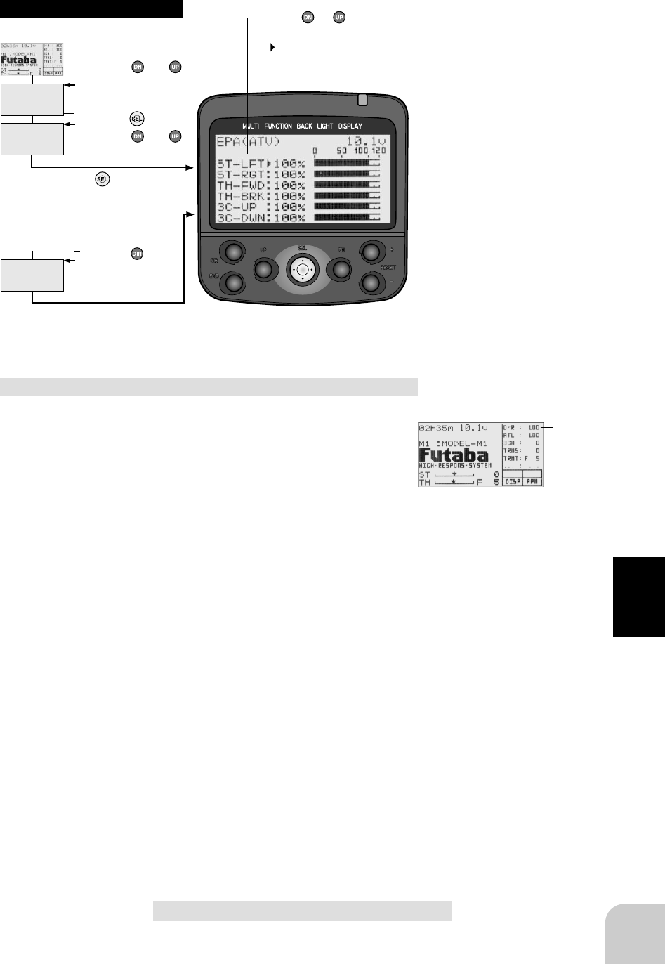
(Initial screen)
MENU
Use the or
button to select the
menu screen.
Press the button.
Use the or
button to select the
function.
Press the button.
Calling the setup screen
* When the direct call button is set,
the setup screen is also called by the
following method:
MENU SELECT
DIRECT SEL
Press the button.
Press the button set
at this function.
* Calling from menu screen Use the or button to
select the setup item.
* blinks at the current
setup item.
(Initial screen)
100%
Setup items
ST-LFT : Steering (left side)
ST-RGT : Steering (right side)
TH-FWD : Throttle (forward side)
TH-BRK : Throttle (brake side)
3C-UP : 3rd channel (up side)
3C-DW : 3rd channel (down side)
Adjustment range
0~120% (each channel, each direc-
tion)
Adjustment buttons
- Use the (+) and (-) buttons to make
adjustments.
- Return to the initial value by pressing
the (+) and (-) buttons simultaneously
(approx. 1 sec).
Steering wheel steering angle (EPA) adjustment
(Preparation)
- Before setup the steering wheel steering angle, set the
steering D/R dial (initial setup: DL1) to the maximum
steering angle position 100%.
- Select setup item "ST-LFT" and make the following
adjustments:
1 Steering (left side) adjustment
Turn the steering wheel fully to the left and use
the (+) and (-) buttons to adjust the steering
angle.
2 Steering (right side) adjustment
Turn the steering wheel fully to the right and use
the (+) and (-) buttons to adjust the steering
angle.
3 When adjusting the steering angle of another
channel immediately after this, see the adjust-
ment method for that channel. When ending ad-
justment, return to the initial screen by pressing
the (END) button three times.
Setup item switching
- Use the (DN) and (UP) buttons to
switch the setup item.
- Others switch the setup item (direc-
tion) linked to the steering wheel.

36
Functions
3rd channel servo steering angle (EPA) adjustment
(Preparation)
- Select setup item "3C-UP" and make the following ad-
justments:
1 3rd channel servo (up side) adjustment
Set the 3rd channel dial fully to the up side (+
side) and use the (+) and (-) buttons to adjust the
steering angle.
2 3rd channel servo (down side) adjustment
Press the (DN) button and select setup item "3C-
DWN" and set the 3rd channel dial fully to the
down side (-) and use the (+) and (-) buttons to
adjust the steering angle.
3 When adjusting the steering angle of another
channel immediately after this, see the adjust-
ment method for that channel. When ending ad-
justment, return to the initial screen by pressing
the (END) button 3 times.
Setup item switching
- Use the (DN) or (UP) button to switch
the setup item.
100%
Throttle steering angle (EPA) adjustment
(Preparation)
- Before setting the throttle steering angle, set the throttle
ATL dial (initial setup: DL2) to the maximum steering
angle position 100%.
- Select setup item "TH-FWD" and make the following
adjustments:
1 Throttle (forward side) adjustment
Pull the throttle trigger fully to the high side and use
the (+) and (-) buttons to adjust the steering angle.
However, when using an FET amp, set to 100%.
2 Throttle (brake side/reverse side) adjustment
Push the throttle trigger fully to the brake side
and use the (+) and (-) buttons to adjust the
steering angle. However, when using an FET
amp, set to 100%.
3 When adjusting the steering angle of another
channel immediately after this, see the adjust-
ment method for that channel. When ending ad-
justment, return to the initial screen by pressing
the (END) button three times.
Setup item switching
- Use the (DN) and (UP) buttons to
switch the setup item.
- Others switch the setup item (direc-
tion) linked with the throttle trigger.
37
Functions
(Initial screen)
MENU
Use the or
button to select the
menu screen.
Press the button.
Use the or
button to select the
function.
Press the button.
Calling the setup screen
* When the direct call button is set,
the setup screen is also called by the
following method:
MENU SELECT
DIRECT SEL
Press the button.
Press the button set
at this function.
* Calling from menu screen
(Initial screen)
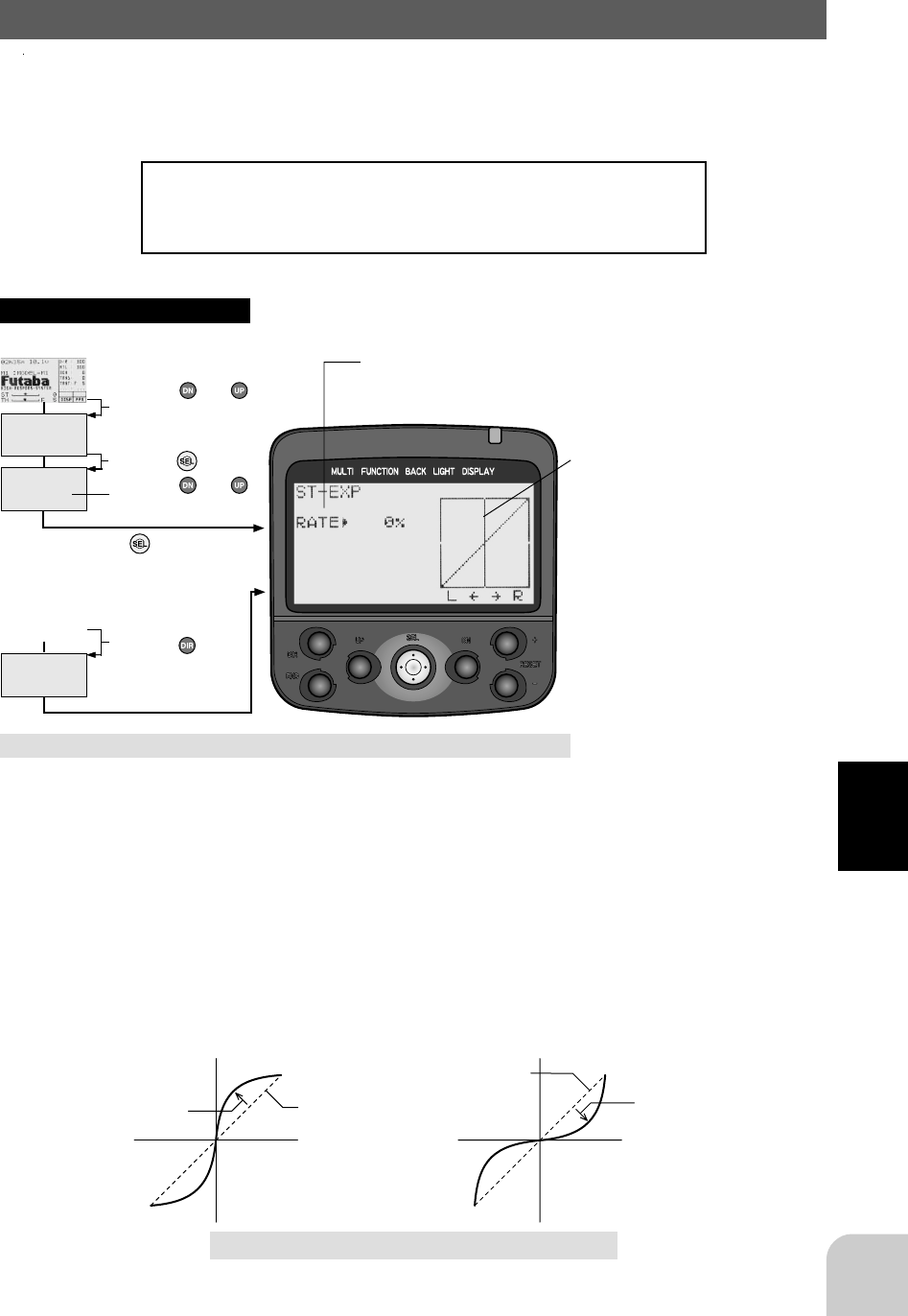
Steering EXP/ST-EXP (Steering system)
This function is used to change the sensitivity of the steering servo around the neutral
position. It has no effect on the maximum servo travel.
Racers Tip
When the setting is not determined, or the characteristics of
the model are unknown, start with 0%. (When EXP is set to
0%, servo movement is linear.)
Setup item
RATE: Steering EXP rate
Vertical cursor moves in step with
steering wheel operation.
Adjustment range
-100~0~+100%
Steering EXP adjustment
1 When you want to quicken steering operation,
use the (+) button to adjust the + side. When you
want to make steering operation milder, use the
(-) button to adjust the - side.
2 When ending adjustment, return to the initial
screen by pressing the (END) button 3 times.
サーボ動作量
ステアリング
スティック
動作量
0%(ノーマル)
+1%∼+100%
(クイック)
サーボ動作量
ステアリング
スティック
動作量
0%(ノーマル) -1%∼ -100%
(マイルド)
(Quick) (Mild)
Servo travel Servo travel
0% (normal)
+1% ~ +100% (quick) 0% (normal) -1% ~ -100% (mild)
Steering wheel travel Steering wheel travel
Adjustment buttons
- Use the (+) and (-) buttons to make
adjustments.
- Return to the initial value by pressing
the (+) and (-) buttons simultaneously
(approx. 1 sec).
38
Functions
(Initial screen)
MENU
Use the or
button to select the
menu screen.
Press the button.
Use the or
button to select the
function.
Press the button.
Calling the setup screen
* When the direct call button is set,
the setup screen is also called by the
following method:
MENU SELECT
DIRECT SEL
Press the button.
Press the button set
at this function.
* Calling from menu screen Use the or button to
select the setup item.
* blinks at the current
setup item.
(Initial screen)
Setup item
TURN: TURN direction
RETURN: RETURN direction
Adjustment range
1~100% (each direction)
Adjustment buttons
- Use the (+) and (-) buttons to make
adjustments.
- Return to the initial value by pressing
the (+) and (-) buttons simultaneously
(approx. 1 sec).
操作時のスピード可変範囲
時間
(約1.5∼0.1秒)
戻りのスピード可変範
囲
(約1.5∼0.1秒)
ス
テ
ィ
ッ
ク
操
作
"TURN"方向
"RETN"方向
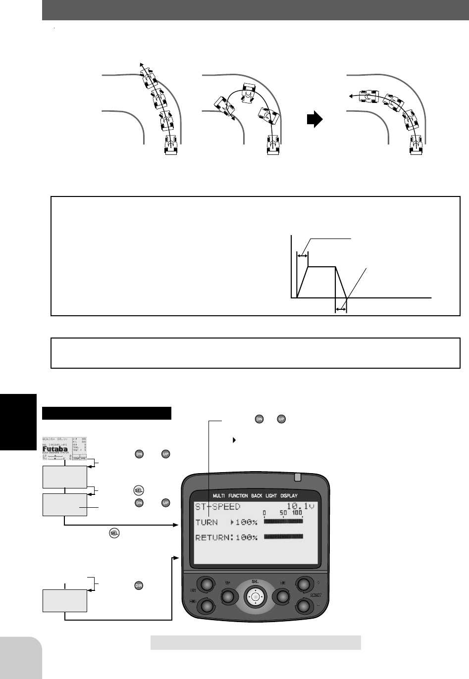
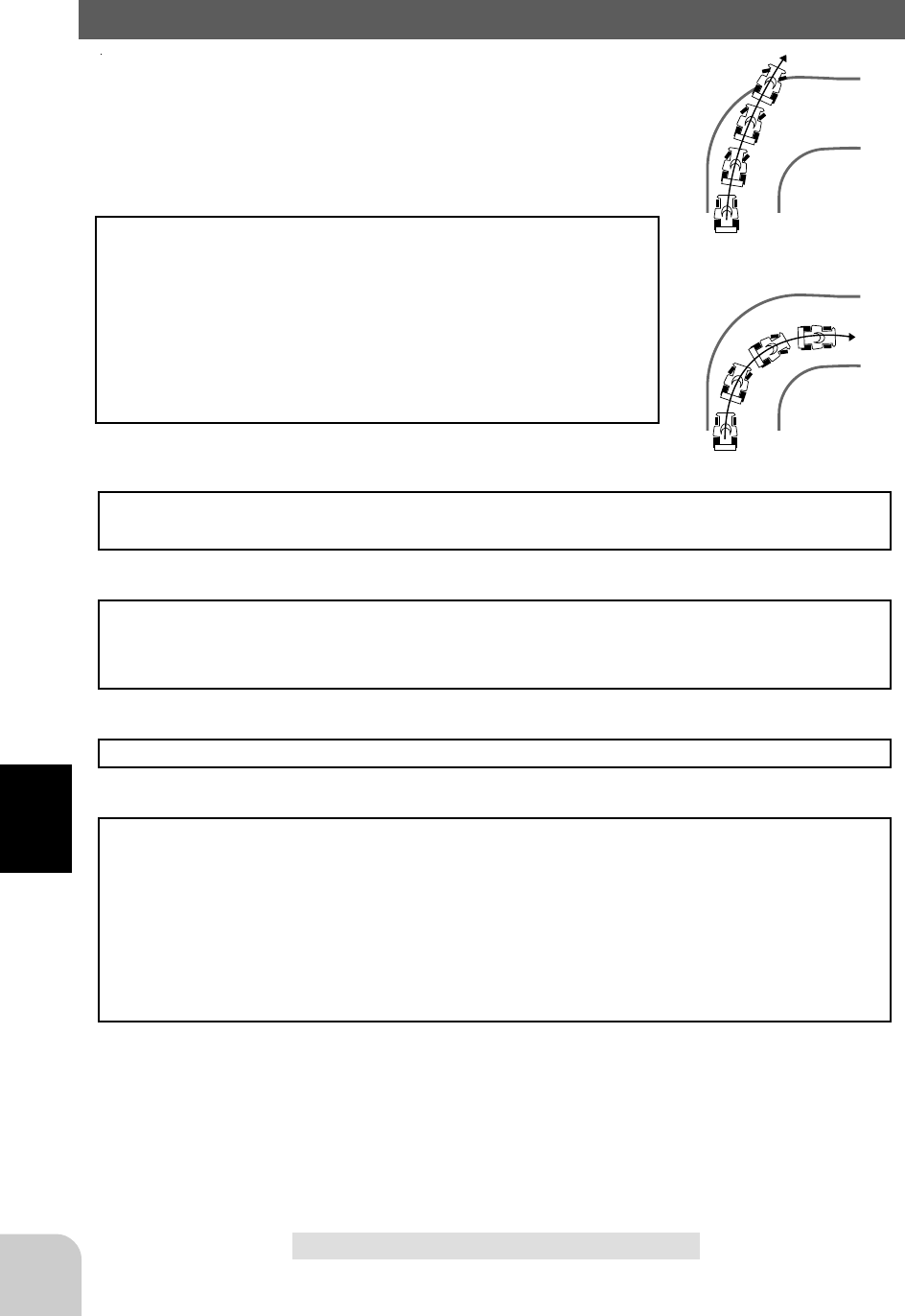
Steering Speed/ST-SPEED (Steering system)
Quick steering operation will cause momentary understeering, loss of speed, or spin-
ning. This function is effective in such cases.
Understeering
Spin
Smooth cornering
Steering speed not set Steering speed set
Operation
- This function limits the maximum speed of
the steering servo. (Delay function)
- The steering speed when the steering wheel
is operated (TURN direction) and returned
(RETN direction) can be independently set.
TURN direction
Turning speed adjustment range
(Approx. 1.5 to 0.1 secs)
Stick operation
RETN direction
Return speed adjust-
ment range (Approx. 1.5
to 0.1 secs)
- If the steering wheel is turned
slower than the set speed, the steer-
ing servo is not affected. Time
Setting example (Steering servo: S9402) . . . (Setting criteria)
- Onroad TURN side: Approx. 50~80% RETN side: Approx. 60~100%
- Offroad TURN side: Approx. 70~100% RETN side: Approx. 80~100%

39
Functions
Steering Speed (ST-SPEED) adjustment
(Preparation)
- Select setup item "TURN" and make the following ad-
justments:
1 "TURN" direction adjustment
Use the (+) and (-) buttons to adjust the delay
amount.
2 3rd channel servo (down side) adjustment
Press the (DN) button and select setup item "RE-
TURN" and use the (+) and (-) buttons to adjust
the delay amount.
3 When ending adjustment, return to the initial
screen by pressing the (END) button 3 times.
Setup item switching
- Use the (DN) or (UP) button to switch
the setup item.
100% 1%
サーボの動作が遅くなる。
Setting range: 1~100%
At 100%, there is no delay.
At 1%, the delay is approximately 1.5
seconds.
Servo operation is delayed.
40
Functions
(Initial screen)
MENU
Use the or
button to select the
menu screen.
Press the button.
Use the or
button to select the
function.
Press the button.
Calling the setup screen
* When the direct call button is set,
the setup screen is also called by the
following method:
MENU SELECT
DIRECT SEL
Press the button.
Press the button set
at this function.
* Calling from menu screen Use the or button to
select the setup item.
* blinks at the current
setup item.
(Initial screen)
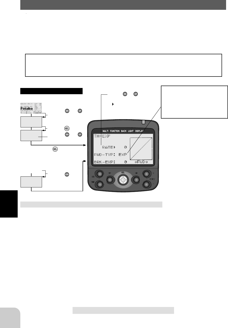
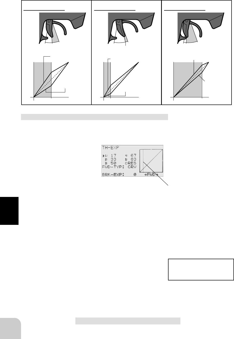
Throttle EXP/TH-EXP (Throttle system)
This function makes throttle trigger high side and brake side direction servo opera-
tion quicker or milder. It has no effect on the servo maximum operation amount.
For the high side, selection from among three kinds of curves (EXP/VTR/CRV) is
also possible.
Advice
When the course conditions are good and there is no sense of torque at the power unit,
set each curve to the + side (quick side). When the road surface is slippery and the
drive wheels do not grip it, set each curve to the - minus (mild) side.
Curve selection
First, select the type of forward side
curve at the "FWD-TYP" item. The
setup item (screen) varies with the
type of curve. The figure at the bottom
left is the EXP curve setup screen.
Setup items
RATE : Forward side rate
FWD-TYP : Forward side curve selection
BRK-EXP : Brake side rate
Adjustment range
RATE : -100 ~ 0 ~ +100%
FWD-TYP : EXP, VTR, CRV
BRK-EXP : -100 ~ 0 ~ +100%
Adjustment buttons
- Use the (+) and (-) buttons to make
adjustments.
- Return to the initial value by pressing
the (+) and (-) buttons simultaneously
(approx. 1 sec).
Adjustment method for EXP curve
(Preparation)
- Select "EXP" at setup item "FWD-TYP".
- Select setup item "RATE" and make the following ad-
justments:
1 Forward side adjustment
Use the (+) button to adjust the + side when you
want to quicken the rise and use the (-) button to
adjust the - side when you want to make the rise
milder.
2 Brake side adjustment
Select "BRK-EXP" by pressing the (DN) button
twice, and use the (+) button to adjust the + side
Setup item switching
0 Use the (DN) or (UP) button to
switch the setup item.
41
Functions
when you want to quicker the rise and use the (-
) button to adjust the - side when you want to
make the rise milder.
3 When ending adjustment, return to the initial
screen by pressing the (END) button 3 times.
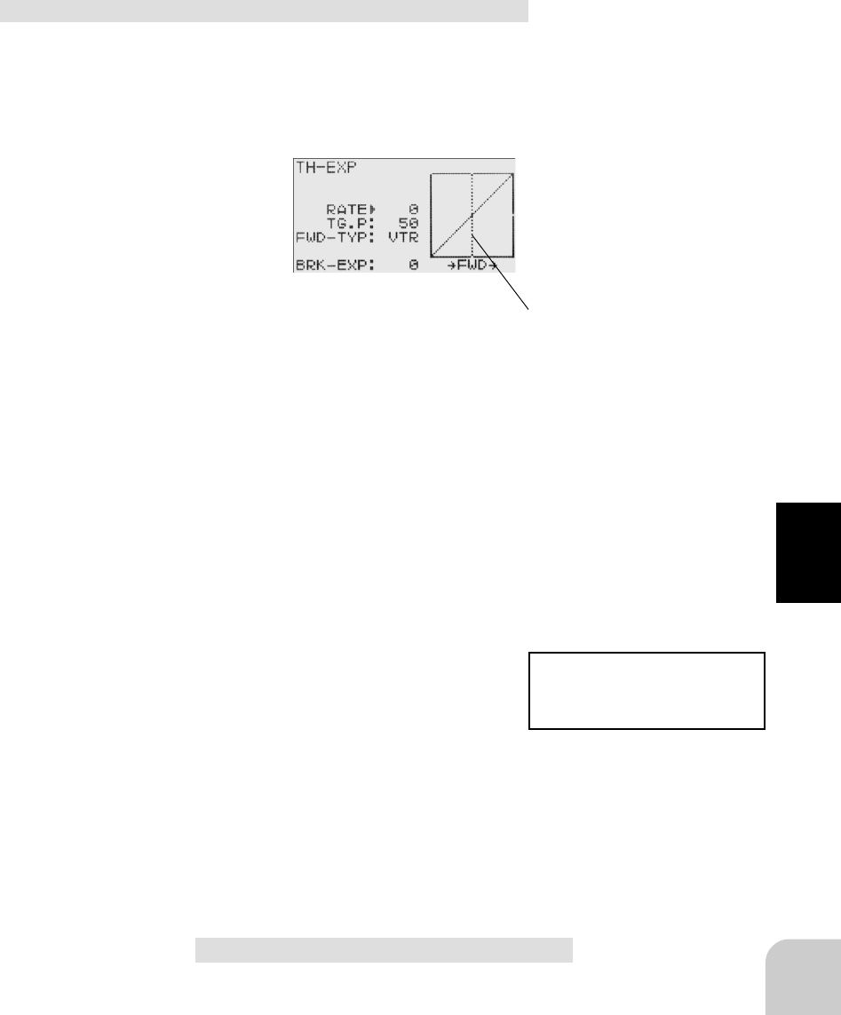
Adjustment method for VTR curve
(Preparation)
- Select "VTR" at setup item "FWD-TYP".
-Select setup item "RATE" and make the following ad-
justments:
Setup items
RATE : Forward rate
TGP : Curve switching point
FWD-TYP : Forward curve selection
BRK-EXP : Brake side rate
Setup item switching
- Use the (DN) or (UP) button to switch the setup item.
1 Forward side adjustment
Use the (+) button to adjust at + side when you
want to quicken the rise and use the (-) button to
adjust the - side when you want to make the rise
milder.
2 Curve switching point adjustment
When you want to change the curve switching
point relative to the throttle stick, select setup
item "TG.P" by pressing the (DN) button and use
the (+) and (-) buttons to move to the point you
want to set.
3 Brake side adjustment
Select setup item "BRK-EXP" by pressing the
(DN) button. When you want to quicken the rise,
use the (+) button to adjust the + side and when
you want to make the rise milder, use the (-) but-
ton to adjust the - side.
4 When ending adjustment, return to the initial
screen by pressing the (END) button 3 times.
Switching point
A vertical cursor line that shows the
curve switching point is displayed on
the setup screen graph.
For the VTR curve, only the high
side can be set. The brake be-
comes the EXP curve.
Adjustment range
RATE : -100 ~ 0 ~ +100%
FWD-TYP : EXP, VTR, CRV
BRK-EXP : -100 ~ 0 ~ +100%
Adjustment buttons
- Use the (+) and (-) buttons to make
adjustments.
- Return to the initial value by pressing
the (+) and (-) buttons simultaneously
(approx. 1 sec).
42
Functions
100% 0%
50%
50%
20%
20%
80%
80%
+1%∼+100%
-1%∼ -100%
+1%∼+100%
-1%∼ -100%
+1%∼+100%
-1%∼ -100%
100% 0%
100% 0%
TG.P=50% TG.P=20% TG.P=80%
Adjustment method for CRV curve
(Preparation)
- Select "CRV" at setup item "FWD-TYP".
Setup items
1:~5: Curve points 1~5
C:RES : Curve reset
FWD-TYP : Forward side curve selection
BRK-EXP : Brake side rate
Setup item switching
- Use the (DN) or (UP) button to switch the setup item.
1 Curve setup
Use the (DN) or (UP) button to select "1:" (1st
point), and use the (+) and (-) buttons to set the
1st point.
Set the throttle curve by sequentially setting "2:"
(2nd point) ~ "5:" (5th point).
2 Brake adjustment
Select setup item "BRK-EXP" by pressing the
(DN) button. When you want to quicken the rise,
use the (+) button to adjust the + side and when
you want to make the rise milder, use the (-) but-
ton to adjust the - side.
3 When ending adjustment, return to the initial
screen by pressing the (END) button 3 times.
Point in current setup
A vertical cursor line that shows the
point in the current setup is displayed
on the setup screen graph.
Returning entire curve to initial value
- Select setup item "C:RES" and re-
turn the set value of each point to the
initial value by simultaneously press-
ing (approx. 1 sec) the (+) and (-) but-
tons.
For the CRV curve, only the high
side can be set. The brake be-
comes the EXP curve.
Adjustment range
1: ~ 5: 0 ~ 100%
FWD-TYP : EXP, VTR, CRV
BRK-EXP : -100 ~ 0 ~ +100%
Adjustment buttons
- Use the (+) and (-) buttons to make
adjustments.
- Return to the initial value by pressing
the (+) and (-) buttons simultaneously
(approx. 1 sec).

43
Functions
Initial values
P1 : 17%
P2 : 33%
P3 : 50%
P4 : 67%
P5 : 83%
100%
50%
0% P1 スティックポイント
P2 P3 P4 P5
設
定
値
初期値
(ノーマルカーブ)
設定例
Throttle curve
Initial value
(normal curve)
Set value
Trigger point
Example
44
Functions
(Initial screen)
MENU
Use the or
button to select the
menu screen.
Press the button.
Use the or
button to select the
function.
Press the button.
Calling the setup screen
* When the direct call button is set,
the setup screen is also called by the
following method:
MENU SELECT
DIRECT SEL
Press the button.
Press the button set
at this function.
* Calling from menu screen Use the or button to
select the setup item.
* blinks at the current
setup item.
(Initial screen)
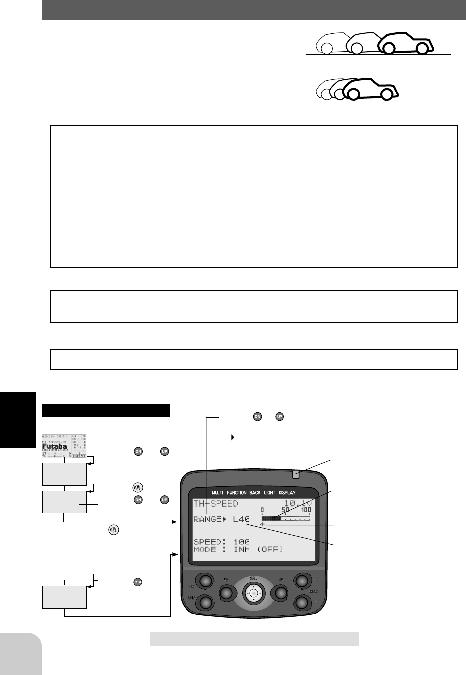
Throttle speed/TH-SPEED (Throttle system)
Sudden trigger operation on a slippery road only
causes the wheels to spin and the vehicle cannot ac-
celerate smoothly. Setting the throttle speed func-
tion reduces wasteful battery consumption while at
the same time permitting smooth, enjoyable opera-
tion.
Operation
Throttle servo (amp) operation is delayed so that the drive wheels will not spin even
if the trigger is operated more than necessary. This delay function is not performed
when the trigger is returned and at brake operation.
- Low side throttle speed (See [Operation range setup].)
Use when adjusting the speed from the neutral position to the set point.
- High side throttle speed (See [Operation range setup].)
Use when adjusting the high side speed from the set point.
Remark: Regarding the throttle speed set value; the actual delay value varies
depending on the system (HRS, PCM, PPM). The delay when the HRS system is used is approximately 1/
3 that of the PCM and PPM systems.
Switch setting
Use PS1, PS2, or PS3 to switch the throttle speed function ON/OFF.
See the function select switch function (page ).
Operation display
* The LED blinks while the throttle speed function is on.
No TH-SPEED/Tires slip and vehicle does not move
TH-SPEED/Smooth, quick starts possible
* The LED blinks while the throttle
speed function is on.
* The black part of the bar graph is the
operation range.
* Throttle trigger position
* "L40" indicates operation below
40%.
Adjustment buttons
- Use the (+) and (-) buttons to make
adjustments.
- Return to the initial value by pressing
the (+) and (-) buttons simultaneously
(approx. 1 sec).
Setup items
RA NGE : Operation range
SPEED : Speed amount
MODE : Function ON/OFF

45
Functions
Throttle speed adjustment
(Preparation)
- Select setup item "MODE" and make the following ad-
justments:
1 (Function ON/OFF)
Set the throttle speed function to the "ACT" state
by pressing the (+) or (-) button.
"INH(OFF)" : Function OFF
"ACT(ON)" : Function ON
"ACT(OFF)": Switch OFF state when setting switches
2 (Operation range setup)
Select setup item "RANGE" by pressing the (UP)
button twice and use the (+) and (-) buttons to set
the operation range.
"L**" : Operate within a range lower than **% (Low side throttle speed)
"H**" : Operation within a range higher than **% (High side throttle speed)
"ALL" : Operate in entire region
"OFF" : Function OFF
3 (Speed amount setup)
Select setup item "SPEED" by pressing the (DN)
button twice and use the (+) and (-) buttons to
adjust the speed amount.
"100" : Maximum speed (no delay)
"0" : Maximum delay
Setup example:
Adjust at the entire (0~100%) range according to conditions.
4 When ending adjustment, return to the initial
screen by pressing the (END) button 3 times.
Operation range:
L1 ~ L40 ~ L99, H1 ~ H99, OFF, ALL
Initial value; L40
Function ON/OFF:
INH(OFF), ACT(ON), ACT(OFF)
Speed amount:
0 ~ 100
Initial value;100
46
Functions
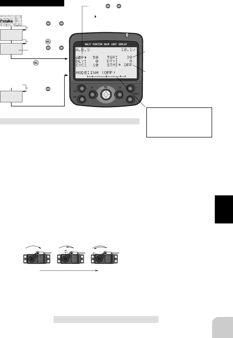
A.B.S. Function
When the brakes are applied while cornering with a 4 Wheel
Drive or other type of vehicle, understeer may occur. The
generation of understeer can be eliminated and corners can
be smoothly cleared by using this function.
Operation
- When the brakes are applied, the throttle servo will pulse
intermittently. This will have the same effect as pumping
the brakes in a full size car.
- The brake return amount, pumping cycle, and brake duty
can be adjusted.
- The region over which the ABS is effective can be set ac-
cording to the steering operation. (Mixing function)
Without A.B.S.
With A.B.S.
Switch Setting
The A.B.S. function ON/OFF switch can be set with the function select switch func-
tion. (Page ) PS1, PS2, or PS3 can be selected.
Dial / Trim Setting
The brake return amount (AB.P), delay amount (ABS.D) and cycle (CYCL) can be
controlled with grip dial DL1, DL2 or digital trim DT3, etc. with the function select
dial function. (Page )
Operation Display
When the A.B.S. function is activated, the LED flashes.
Fail Safe Unit
When the 3PK is used with the Futaba fail safe unit (FSU-1), it will operate as de-
scribed below.
- When the FSU-1 is connected to the throttle channel, and the A.B.S. function has
been activated, the FSU-1 LED will flash each time the servo operates. The reason
for this is that the FSU-1 responds to sudden data changes caused by A.B.S. function
pumping operation. It does not mean that the fail safe function is activated. The servo
will not be affected.
47
Functions
(Initial screen)
MENU
Use the or
button to select the
menu screen.
Press the button.
Use the or
button to select the
function.
Press the button.
Calling the setup screen
* When the direct call button is set,
the setup screen is also called by the
following method:
MENU SELECT
DIRECT SEL
Press the button.
Press the button set
at this function.
* Calling from menu screen Use the or button to
select the setup item.
* blinks at the current
setup item.
(Initial screen)
0% 100%
Setup items
ABP : Brake return amount
DLY : Delay amount
CYC : Cycle speed
MODE : Function ON/Off
TGP : Operation point
DTY : Cycle duty ratio
STM : Steering mixing
* When brake operation enters the set
range, "*" is displayed in front of the
number.
* When steering mixing is set and
steering operation enters the set
range, "*" is displayed in front of the
number. When mixing is OFF, the
A.B.S function can operate over the
entire steering range.
* A bar graph that shows the oper-
ating position of the throttle trigger
appears. During setup, A.B.S func-
tion operation can be checked at
this bar graph.
A.B.S function adjustment
(Preparation)
- Select setup item "MODE" and make the following ad-
justments:
1 (Function ON/OFF)
Set the function to the active state by pressing
the (+) or (-) button.
"INH(OFF)" : Function OFF
"ACT(ON)" : Function ON
"ACT(OFF)" : Switch OFF when setting switches
2 (Brake return amount adjustment)
Select setup item "ABP" by pressing the (UP)
button 3 times and use the (+) and (-) buttons to
adjust the return amount.
"0" : No return
"50" : Return to the 50% position of the brake operation amount
"100" : Return to the neutral position.
3 (Delay amount setup)
Select setup item "DLY" by pressing the (DN)
button once and use the (+) and (-) buttons to
adjust the delay amount.
"0" : A.B.S. function performed without any delay
"50" : A.B.S function performed after an approximate 0.7 sec delay.
"100" : A.B.S. function performed after an approximate 1.7 secs delay.
Function ON/OFF:
INH(OFF), ACT(ON), ACT(OFF)
Delay amount:
0 ~ 100
Initial value; 0
Adjustment buttons
- Use the (+) and (-) buttons to make
adjustments.
- Return to the initial value by pressing
the (+) and (-) buttons simultaneously
(approx. 1 sec).
Brake return amount:
0 ~ 50 ~ 100
Initial value; 50
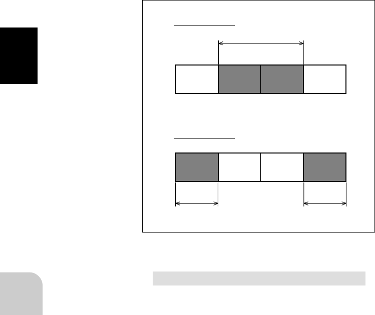
48
Functions
4 (Cycle speed adjustment)
Select setup item "CYC" by pressing the (DN)
button once and use the (+) and (-) buttons to
adjust the speed.
- The lower the set value, the faster the cycle speed.
5 (Operation point setup)
Select set item "TGP" by pressing the (DN) but-
ton twice, and use the (+) and (-) buttons to set
the operation point.
- Sets the throttle trigger position at which the A.B.S. function is per-
formed. The number is the % display with the brake position made 100.
6 (Cycle duty ratio setup)
Select setup item "DTY" by pressing the (DN)
button once, and use the (+) and (-) buttons to
adjust the duty ratio.
"-3" : Brake application time becomes shortest. (Brakes lock with difficulty)
"+3" : Brake application time becomes longest (Brakes lock easily)
(Remark) For low grip, set at the - side and for high grip, set at the + side.
7 (Steering mixing setup)
Select setup item "STM" by pressing the (DN)
button once, and use the (+) and (-) buttons to
set the steering mixing range.
- Sets the range within which the A.B.S. function is performed relative to
steering wheel operation.
N50%の場合
L(E) N R(E)
L(E) N50% 50%
50%
*マークが表示され
A.B.S.が働く範囲
*マークが表示され
A.B.S.が働く範囲 *マークが表示され
A.B.S.が働く範囲
50%
R(E)
E50%の場合
N50%
A.B.S. operation range indicated by *
E50%
A.B.S operation range
indicated by *
A.B.S operation range
indicated by *
Cycle speed
1 ~ 30
Initial value; 10
Operation point
10 ~ 100
Initial value; 30
Duty ratio
-3 ~ 0 ~ +3
Initial value; 0
Steering mixing
OFF, N10 ~ N100, E10 ~ E100
Initial value; OFF
8 When ending adjustment, return to the initial
screen by pressing the (END) button 3 times.

49
Functions
Example of A.B.S. function setting when S9402 used (There will be a slight
difference depending on the state of the linkage.)
- Basic setting
AB.P: Approx. 30% (If this value is too high, the braking distance will increase.)
CYCL: 5~7
DUTY: 0 (When grip is low: - side, when grip is high: + side)
DLY: 10~15%
TG.P: Approx. 70%
STM: OFF
- When the wheels lock, or the car spins, when the brakes are applied fully
AB.P: Increase from 30%
DUTY: Shift from 0 to - side (-1, -2, -3)
DLY: Reduce the delay
- When the braking effect is poor and the braking distance is long when the brakes are
applied fully
AB.P: Decrease from 30%
DUTY: Shift from 0 to + side (+1, +2, +3)
DLY: Increase the delay