Futaba FRH-SD07TU RF Modem using digital modulation User Manual
Futaba Corporation RF Modem using digital modulation Users Manual
UserManual.wiki
>
Futaba
>
FRH-SD07TU User Manual
>
Users Manual
Contents
1.
Users Manual
2.
User Manual
Users Manual
Navigation menu
Upload a User Manual
Namespaces
Wiki Guide
HTML
PDF
Info
Views
User Manual
Discussion / Help
Navigation
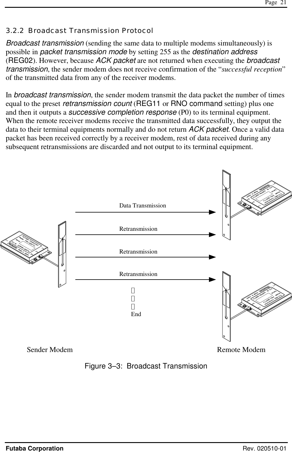
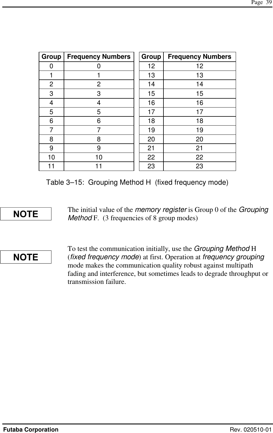
![Page i Futaba Corporation Rev. 020510-01 I Notice This device complies with part 15 of the FCC rules and with ETS 300 440 of the European Telecommunication Standard Institute (ETSI). Operation is subject to the following two conditions: (1) This device may not cause harmful interference, and (2) this device must accept any interference received, including interference that may cause undesired operation. This equipment has been tested and found to comply with the limits for a Class A digital device, pursuant to part 15 of the FCC Rules. These limits are designed to provide reasonable protection against harmful interference when the equipment is operated in a commercial environment. This equipment generates, uses, and can radiate radio frequency energy and, if not installed and used in accordance with the instruction manual, may cause harmful interference to radio communications. Operation of this equipment in a residential area is likely to cause harmful interference in which case the user will be required to correct the interference at his own expense. Any unauthorized changes or modifications to this device not expressly approved by Futaba Corporation could void the user’s authority to operate the device and possibly result in damage to the equipment and/or cause serious or fatal injuries to the operator or nearby personnel. This device is intended to be installed and used in accordance with the instructions contained in this manual. Failure to comply with these instructions could void the user’s authority to operate the device and possibly result in damage to the equipment and/or cause serious or fatal injuries to the operator or nearby personnel. [Especially for users in Europe] FRH-SD07TB, European version can be used in the following countries: Austria, Belgium, Denmark, Estonia, Finland, France, Germany, Greece, Iceland, Ireland, Italy, Luxembourg, Norway, Portugal, Spain, Sweden, Switzerland, The Netherlands and United Kingdom (the Czech Republic and Hungary with limitation, see below). In France and Spain, usable frequency is limited by its country’s regulatory authority. See p.35 FREQUENCY GROUPING for the frequency usage limitation. Belgium does not authorize FRH-SD07TB itself. FRH-SD07TB must be fitted into the final product, then tested to Radio, EMC and safety requirements. A notification will be only accepted for the final product then. Users in the Czech Republic and Hungary can use FRH-SD07TB modem, but it has some limitation for operation. Please contact local regulatory authority to obtain details before attempt to use FRH-SD07TB modem in that countries.](https://usermanual.wiki/Futaba/FRH-SD07TU.Users-Manual/User-Guide-251104-Page-3.png)
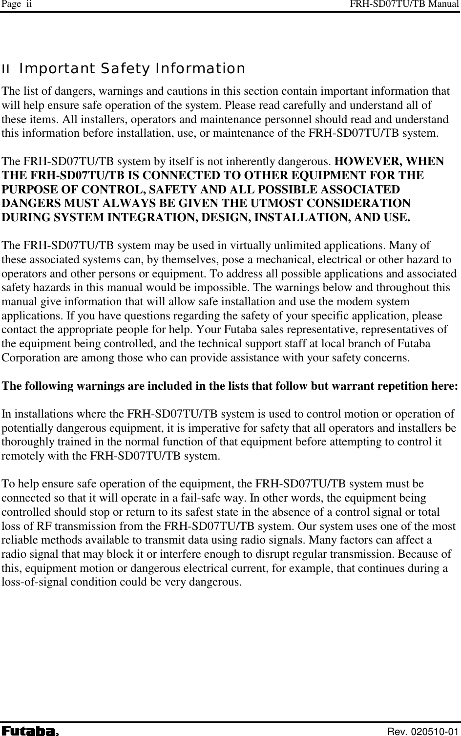
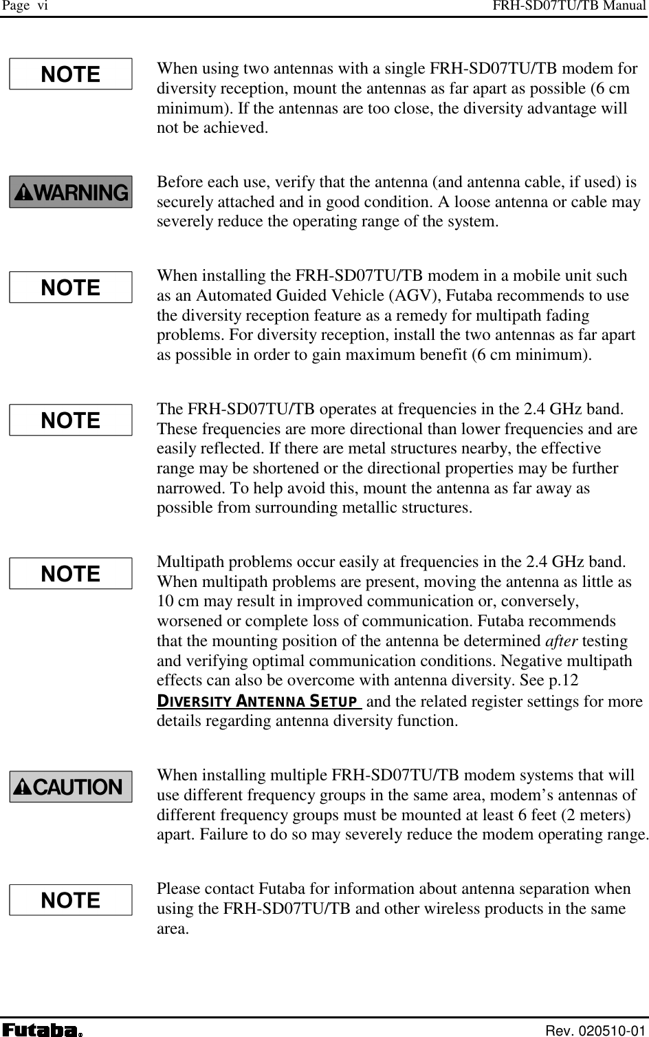
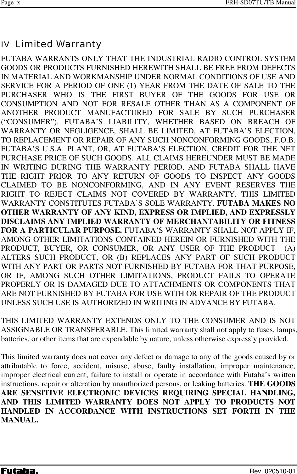

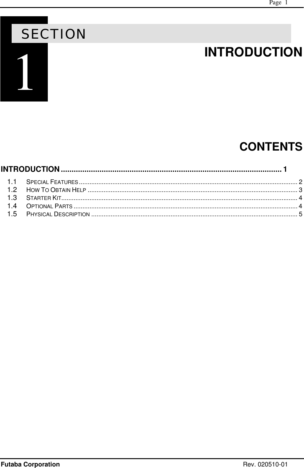
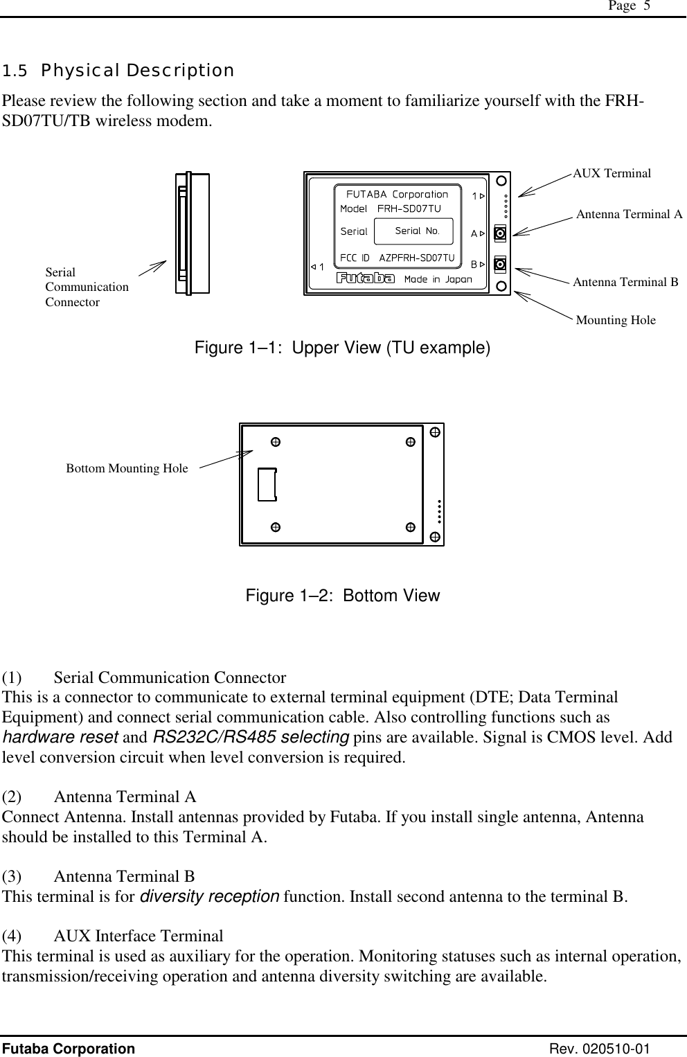
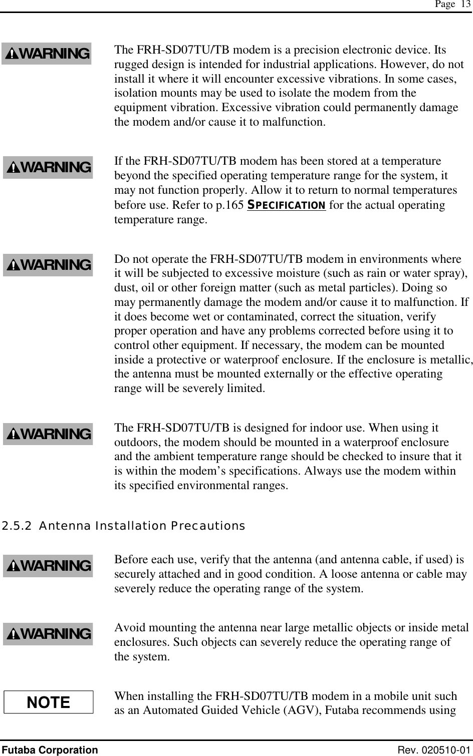
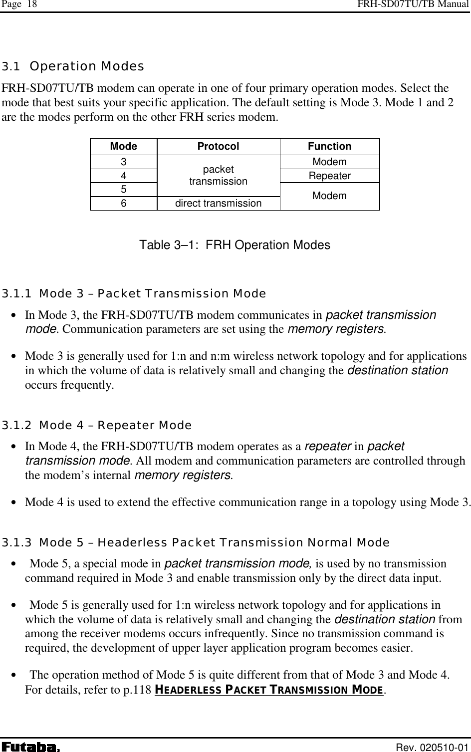
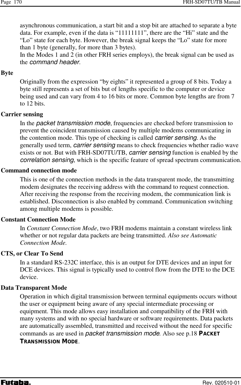
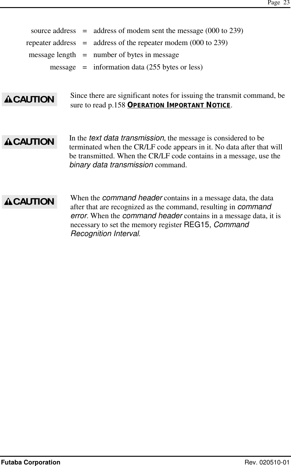
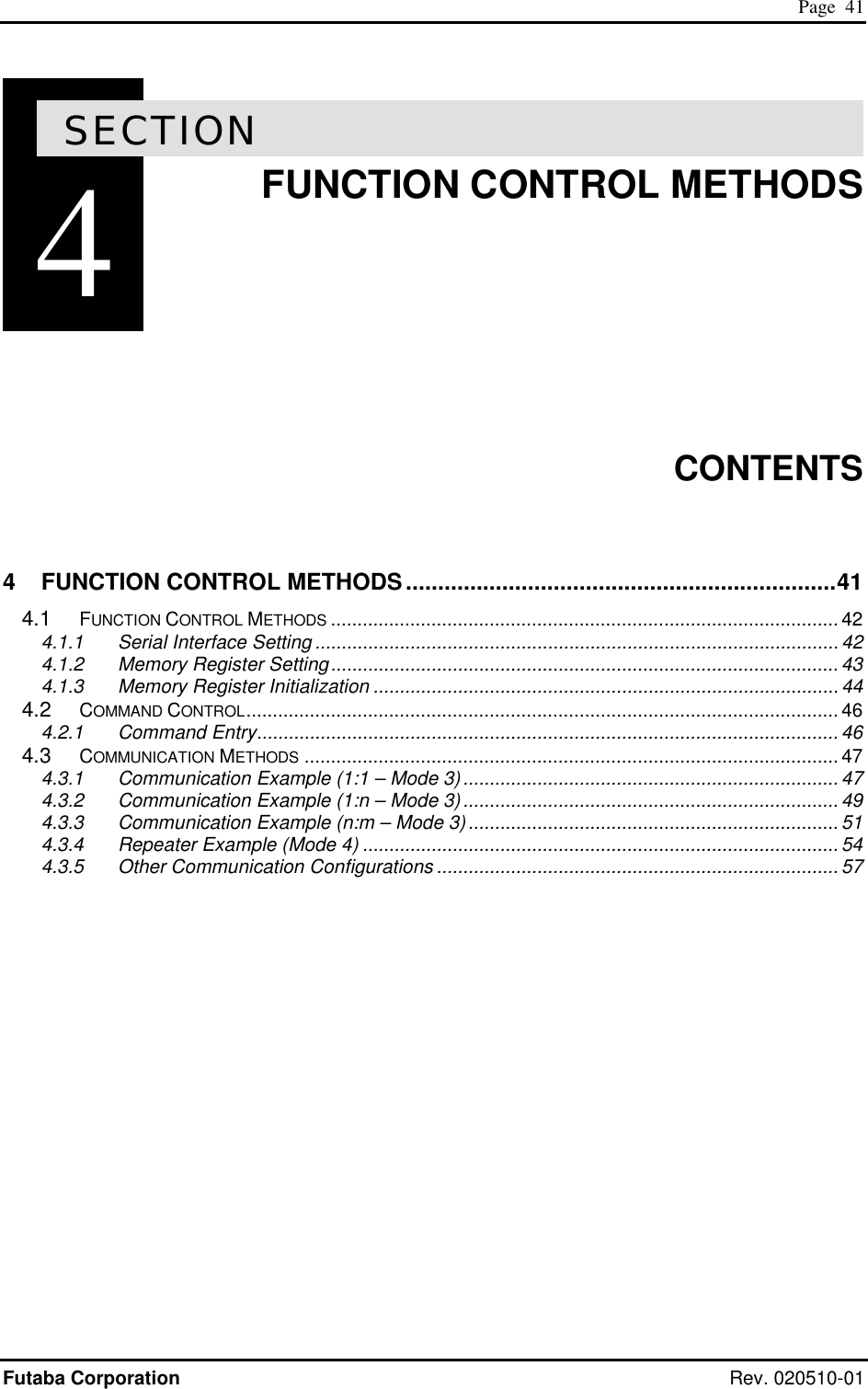
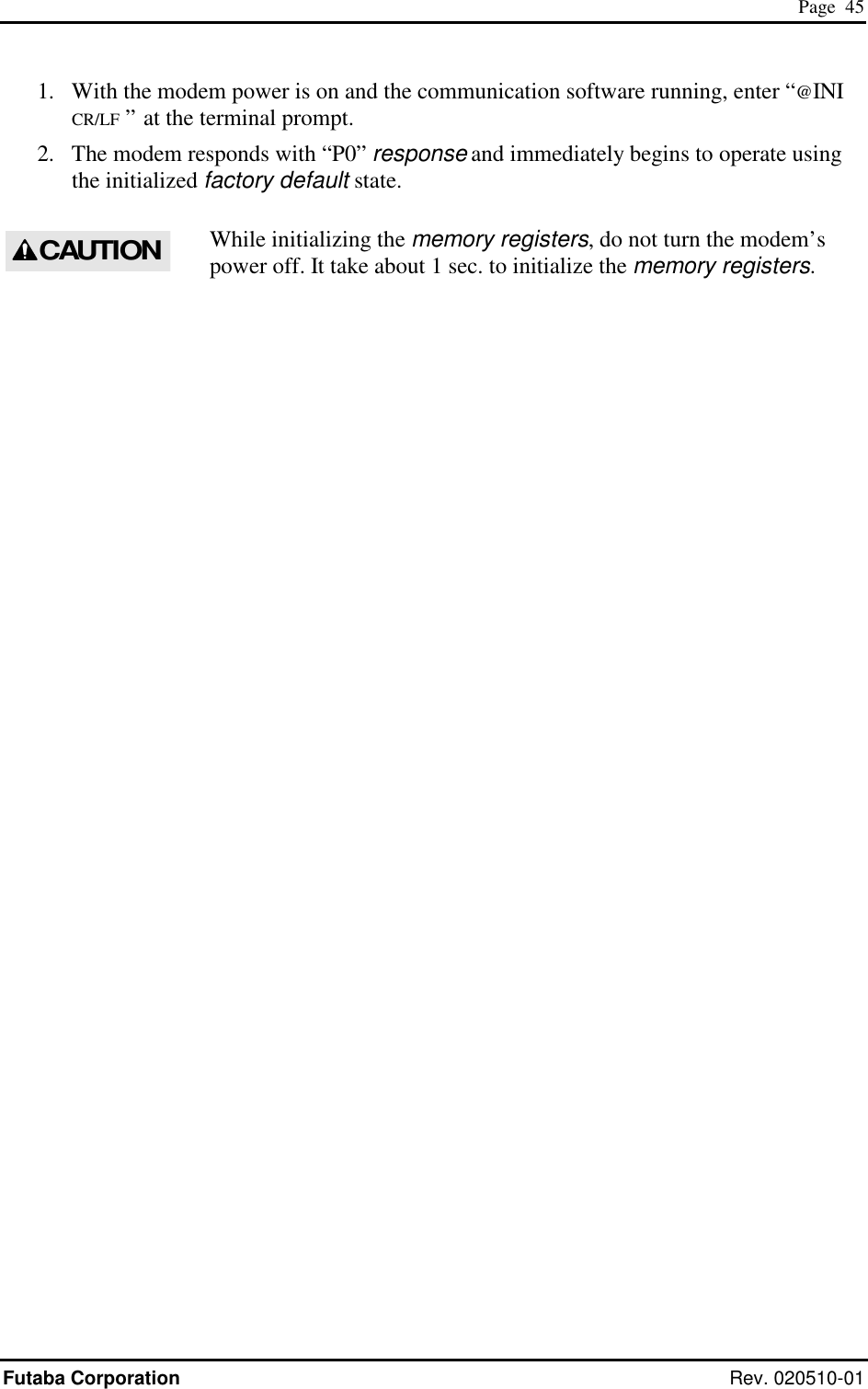
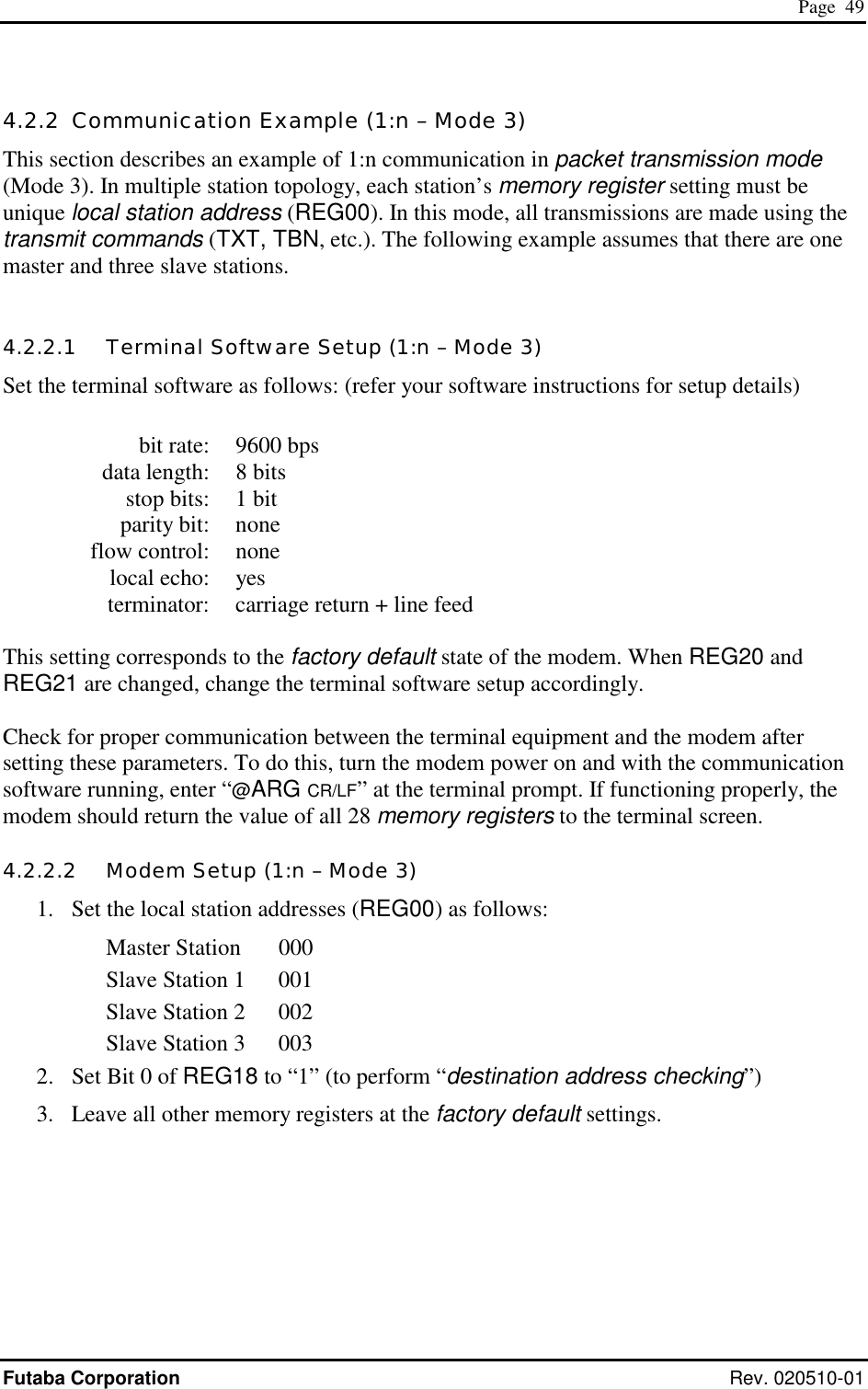
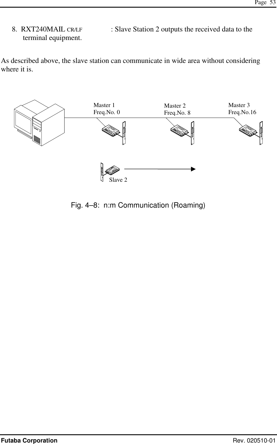
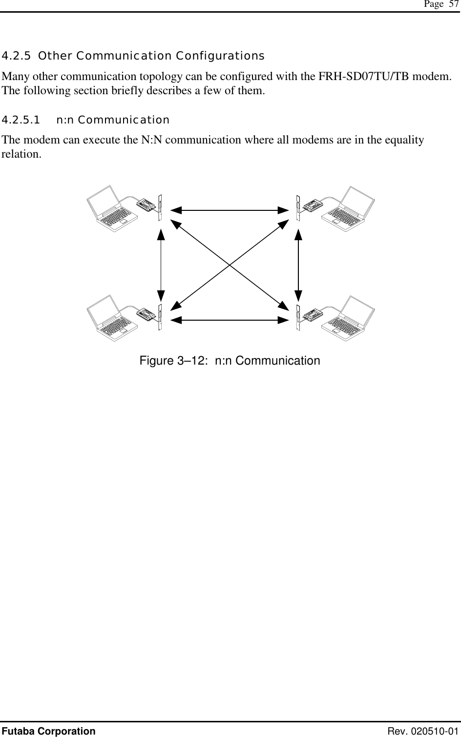
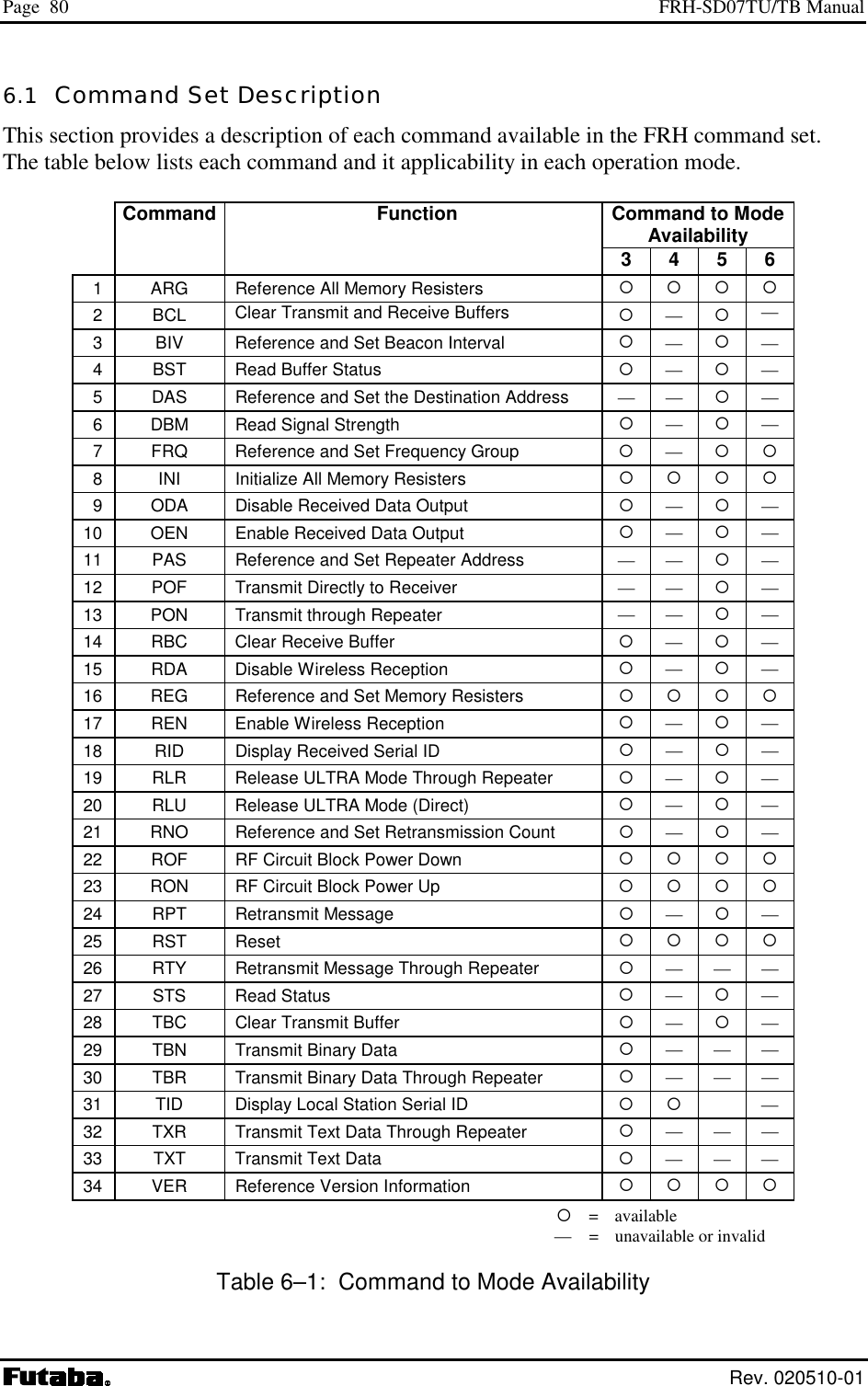
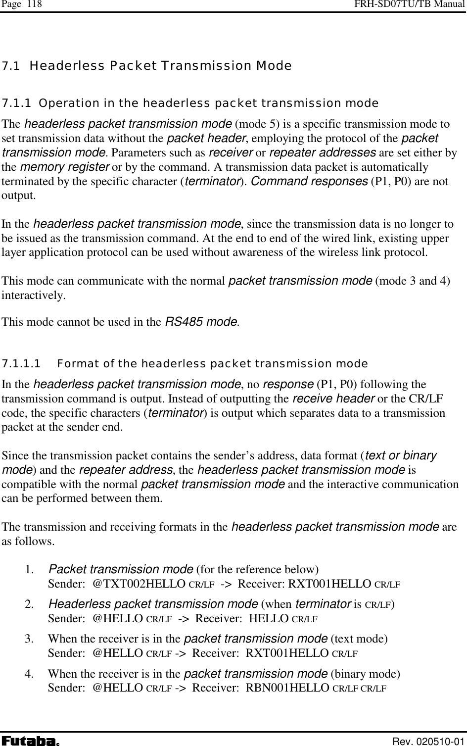
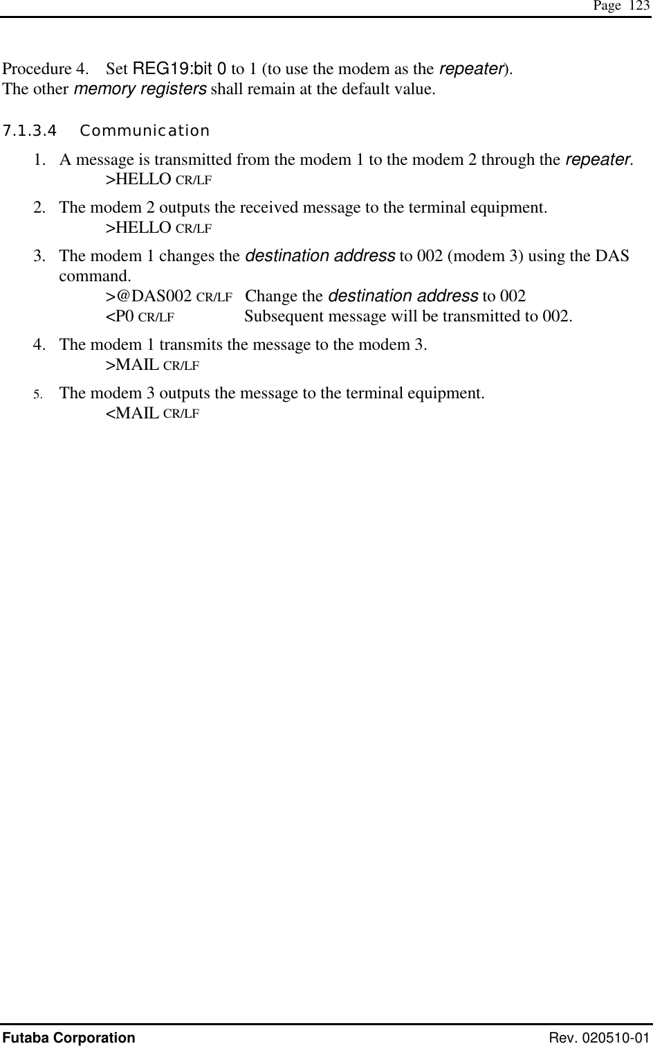
![Page 22 FRH-SD07TU/TB Manual Rev. 020510-01 3.2.3 Transmit Command and Receive Header Four transmit commands can be used in packet transmission mode (mode 3). Both text and binary data can be sent directly from modem-to-modem or sent through a third FRH (series) modem configured as a repeater. The receiver modem automatically determines the transmitted data format and communication path from the information in the received packet header. Refer to the table below for a list of the transmit commands and the corresponding header component. Transmit Command Receive Header Function TXT RXT Text data transmission TBN RBN Binary data transmission TXR RXR Text data transmission via repeater TBR RBR Binary data transmission via repeater Table 3–5: Transmit Commands and Receive Headers The following list shows each command’s syntax as issued at the sender terminal equipment and the response displayed at the receiver terminal equipment when the packet is received. 1. Direct Text Data Transmission transmit: @TXT [destination address]{source address}[message] receive: RXT [source address][message] CR/LF 2. Direct Binary Data Transmission transmit: @TBN[destination address]{source address}[message length][message] CR/LF receive: RBN [source address][message length][message] CR/LF 3. Text Data Transmission through Repeater transmit: @TXR [repeater address][destination address]{source address} [message] CR/LF receive: RXR [repeater address][source address][message] CR/LF 4. Binary Data Transmission through Repeater transmit: @TBR [repeater address][destination address]{source address} [message length][message] CR/LF receive: RBR [repeater address][source address][message length][message] CR/LF where {source address} is optional, used in RS485 mode set by serial communication cable 12 pin. The following list defines the parameters and symbols used in the commands above: @ = command header CR/LF = carriage return + line feed destination address = address of modem to receive the message (000 to 239)](https://usermanual.wiki/Futaba/FRH-SD07TU.Users-Manual/User-Guide-251104-Page-38.png)
![Page 31 Futaba Corporation Rev. 020510-01 Receive throughput will drop since the frequency between the sender modem and receiver modem is not identical in some case (because multiple frequencies are used). When using the frequency group function, receiver modems are in the ready-to-receive state and is sequentially changing frequencies. A sender modem, that has data to be transmitted, also transmits its packet sequentially with changing frequencies until it receives ACK from the receiver modem or until it reaches the retransmission count plus one. Because the receiving modem changes frequencies at a slower rate than the transmitting modem, the both frequency channels will eventually align. And the data packet will be successfully transmitted. To make frequency alignment in both mode, the retransmission count should be set high enough. But sometimes, it takes a time to make this alignment. The use of the frequency group function is effective when specific frequencies are interfered, but will result a degradation of data throughput. Accordingly, it is recommended to use the fixed frequency mode for applications that require high data throughput in the packet transmission mode. (In this case, the communication may be susceptible to interference or multipath fading) 3.2.6.3 Collision Avoidance in RS485 Interface When multiple modems are connected on RS485 wire-line, the received data or the command responses of the modem may collide on the line. Reasons of such collision are that multi-dropped multiple modems receive packet at the same time and output to RS485 line, or, multiple modems accept global addressing command and output its response at the same time. When there is a possibility of the RS485 line collision, avoid it by taking following remedy. 1) Set each of the multi-dropped modem’s Interval between packets (REG07) value to different value. Difference between each set value shall be larger than 1 byte transmission duration (from the start bit to the stop bit) which determined by the RS485 line baud rate. 2) Set the Collision avoidance function (REG23:bit 1) of all modems to 1. 3) Set Regular interval output for RS485 collision avoidance (REG23:bit 2) to 1 of the modem which Interval between RS485 packets (REG07) is set to the longest The above remedy is set to the multiple modems that are multi-dropped, the modem which set REG07 interval to the longest outputs regularly CR code [0DH] when all modem has no data to output. This enables timing synchronization of all of the modems to start measuring the interval time between RS485 data packets to packet. This results that data will not be output from multiple modems at the same time since the interval between RS485 packets (REG07) of each modem is set to different values. Also the modem can detects another station’s RS485 data transmission status since the interval difference is set more than 1 byte time. Eventually, this can avoid collision on the RS485 line since the modem can wait for their turn to output RS485 data.](https://usermanual.wiki/Futaba/FRH-SD07TU.Users-Manual/User-Guide-251104-Page-47.png)
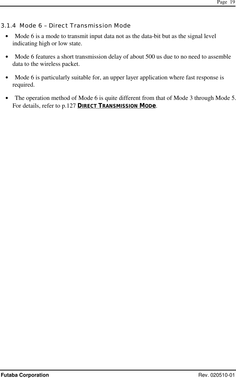
![Page 59 Futaba Corporation Rev. 020510-01 5SECTION 5 MEMORY REGISTER DESCRIPTION CONTENTS 5 MEMORY REGISTER DESCRIPTION ..............................................................59 5.1 MEMORY REGISTER DESCRIPTION ............................................................................................ 60 REG00: LOCAL STATION ADDRESS [DEFAULT VALUE: 00H].............................................................. 61 REG01: LOCAL STATION GLOBAL ADDRESS [DEFAULT VALUE: F0H]................................................. 61 REG02: DESTINATION ADDRESS [DEFAULT VALUE: 00H] ................................................................. 61 REG03: SPECIAL SETTING [DEFAULT VALUE: F0H].......................................................................... 61 REG04: ID CODE 1 [DEFAULT VALUE: 00H] .................................................................................... 61 REG05: ID CODE 2 [DEFAULT VALUE: 00H] .................................................................................... 62 REG06: FREQUENCY GROUP [DEFAULT VALUE: A0H]...................................................................... 62 REG07: PACKET INTERVAL [DEFAULT VALUE: 05H].......................................................................... 63 REG08: RESERVED [DEFAULT VALUE: 11H] .................................................................................... 63 REG09: RESERVED [DEFAULT VALUE: 13H] .................................................................................... 63 REG10: COMMAND HEADER [DEFAULT VALUE: 40H]........................................................................ 63 REG11: RETRANSMISSION COUNT [DEFAULT VALUE: 32H]............................................................... 64 REG12: ROAMING THRESHOLD [DEFAULT VALUE: B4H]................................................................... 64 REG13: RESERVED [DEFAULT VALUE: 1EH].................................................................................... 64 REG14: RECEIVE DATA OUTPUT INTERVAL [DEFAULT VALUE: 00H].................................................. 64 REG15: COMMAND RECOGNITION INTERVAL [DEFAULT VALUE: 00H]................................................64 REG16: COMMAND INPUT TIMEOUT [DEFAULT VALUE: 32H]............................................................. 65 REG17: RESERVED [DEFAULT VALUE: 32H] .................................................................................... 65 REG18: COMMUNICATION SETTING 1 [DEFAULT VALUE: 8CH].......................................................... 66 REG19: COMMUNICATION SETTING 2 [DEFAULT VALUE: 00H] .......................................................... 67 REG20: RS-232C SETTING 1 [DEFAULT VALUE: 05H]..................................................................... 69 REG21: RS-232C SETTING 2 [DEFAULT VALUE: 09H]..................................................................... 70 REG22: RS-232C SETTING 3 [DEFAULT VALUE: 00H]..................................................................... 72 REG23: MISCELLANEOUS SETTINGS [DEFAULT VALUE: 00H]............................................................ 74 REG24: SPECIAL MODE SETTINGS [DEFAULT VALUE: C0H].............................................................. 76 REG25: ULTRA MODE SETTINGS [DEFAULT VALUE: 40H]............................................................... 77 REG26: RESERVED [DEFAULT VALUE: 00H] .................................................................................... 77 REG27: FREQUENCY BAND SETTINGS [DEFAULT VALUE: 01H] ......................................................... 78](https://usermanual.wiki/Futaba/FRH-SD07TU.Users-Manual/User-Guide-251104-Page-75.png)
![Page 61 Futaba Corporation Rev. 020510-01 REG00: Local Station Address [default value: 00H] • Sets the local station address. Valid values are 000 to 239. (240 addresses) • This value is inserted in the “source address” field in the transmitted packet header. • If the address check function is enabled (REG18) in the receiving modem, the modem can receive the packet which header contains destination address information identical to REG00. • In the RS485 mode, this register is used as 485 mode local station address. REG01: Local Station Global Address (RS485) [default value: F0H] • Sets the local station global address of the modem. Valid values are 240 to 254. (15 addresses) • When plural modems are connected by RS485 multi-dropping topology, commands can be issued to multiple modems simultaneously by setting all connected modems to the same global address. This is the global addressing. • This global addressing allows to handle multiple multi-dropped modems as if they were one modem. REG02: Destination Address [default value: 00H] • This address is used in the headerless packet transmission mode (communication modes 5). For details, refer to p.118 HEADERLESS PACKET TRANSMISSION MODE. • Use the default value for the transmission mode 3 or 4. REG03: Special Setting [default value: F0H] • Sets special operation modes such as headerless packet transmission mode or direct transmission mode. Refer to p.117 ADVANCED APPLICATION. • Use the default value for the transmission mode 3 or 4. REG04: ID Code 1 [default value: 00H] • Used with ID code 2 (REG05), set the ID code. Valid values are 000 to 255. Together with ID code 2, up to 61,440 ID codes can be set. • The ID code identifies the group of the modems works in the same group. The ID code is used to prevent erroneous connection with other systems and for communication security.](https://usermanual.wiki/Futaba/FRH-SD07TU.Users-Manual/User-Guide-251104-Page-77.png)
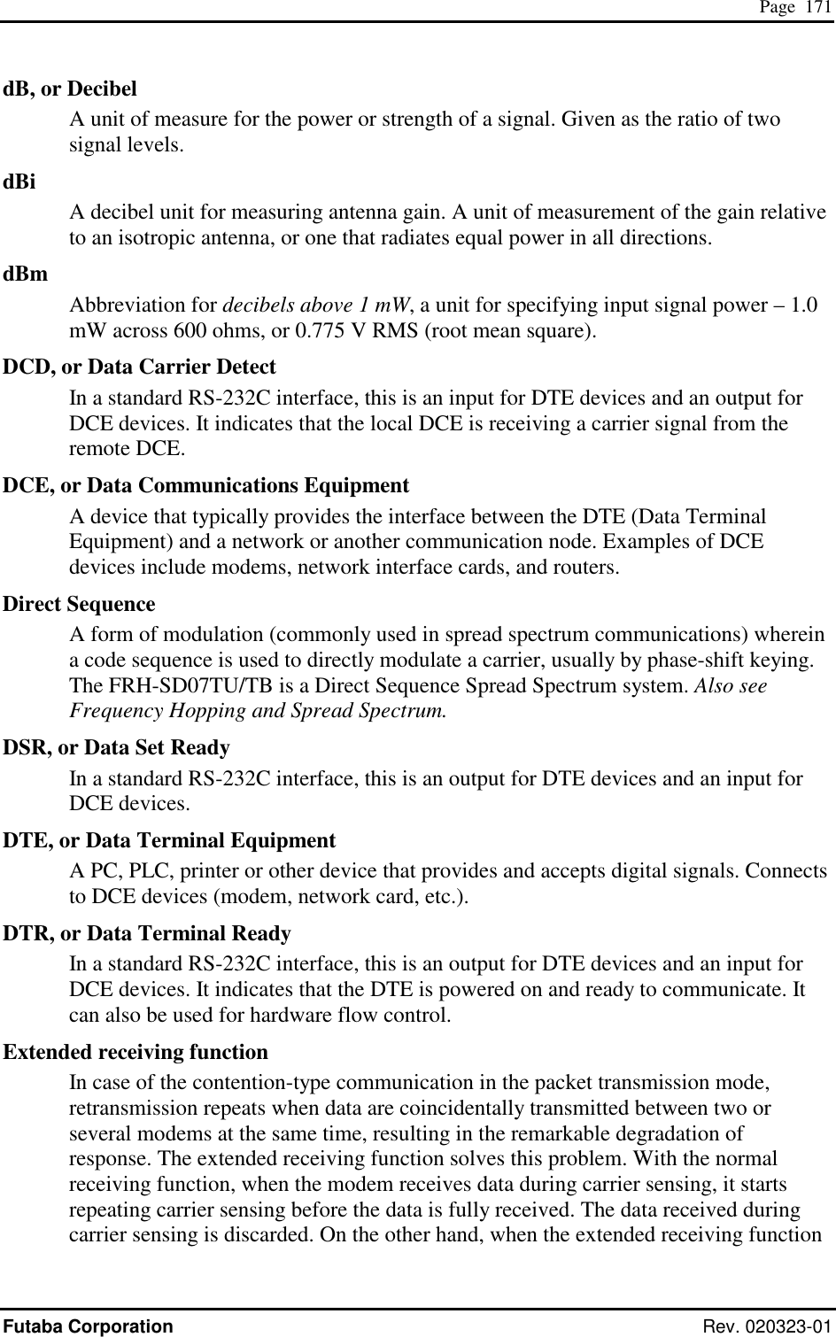
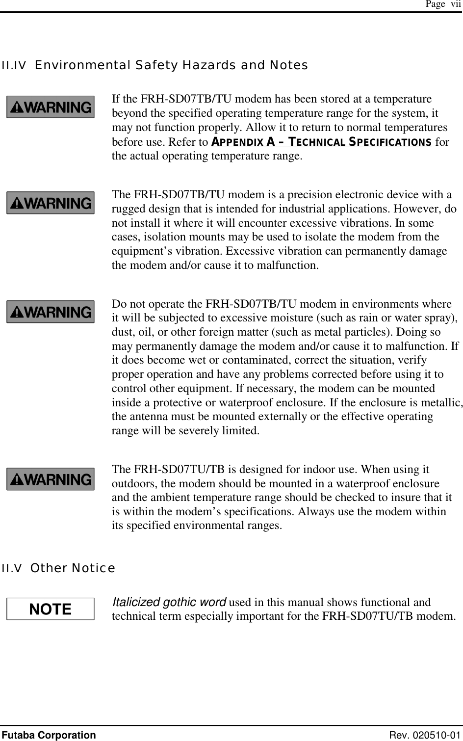
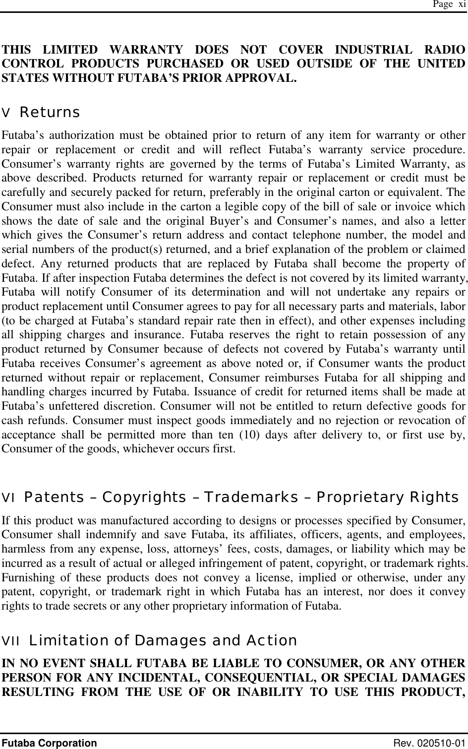
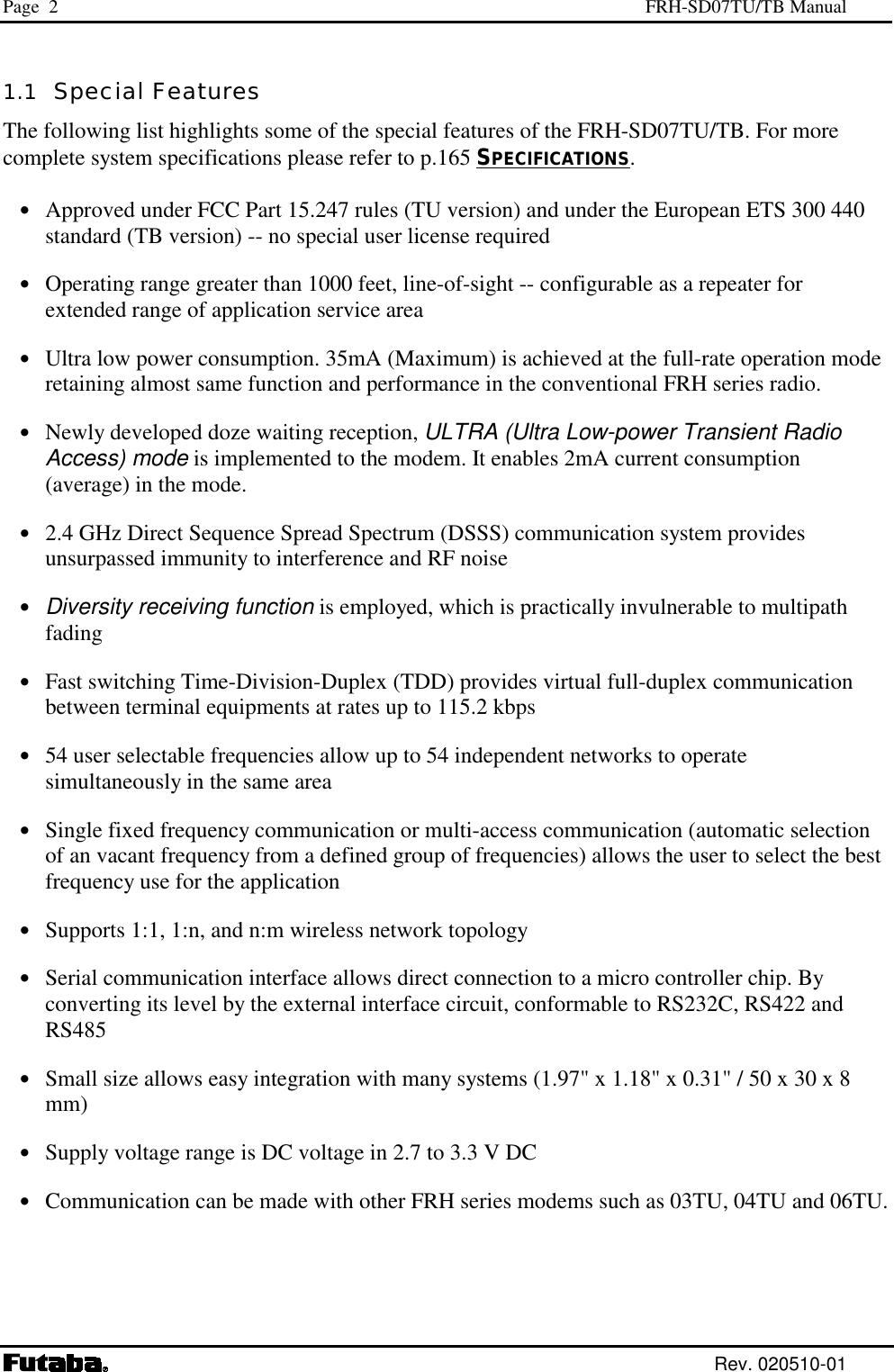
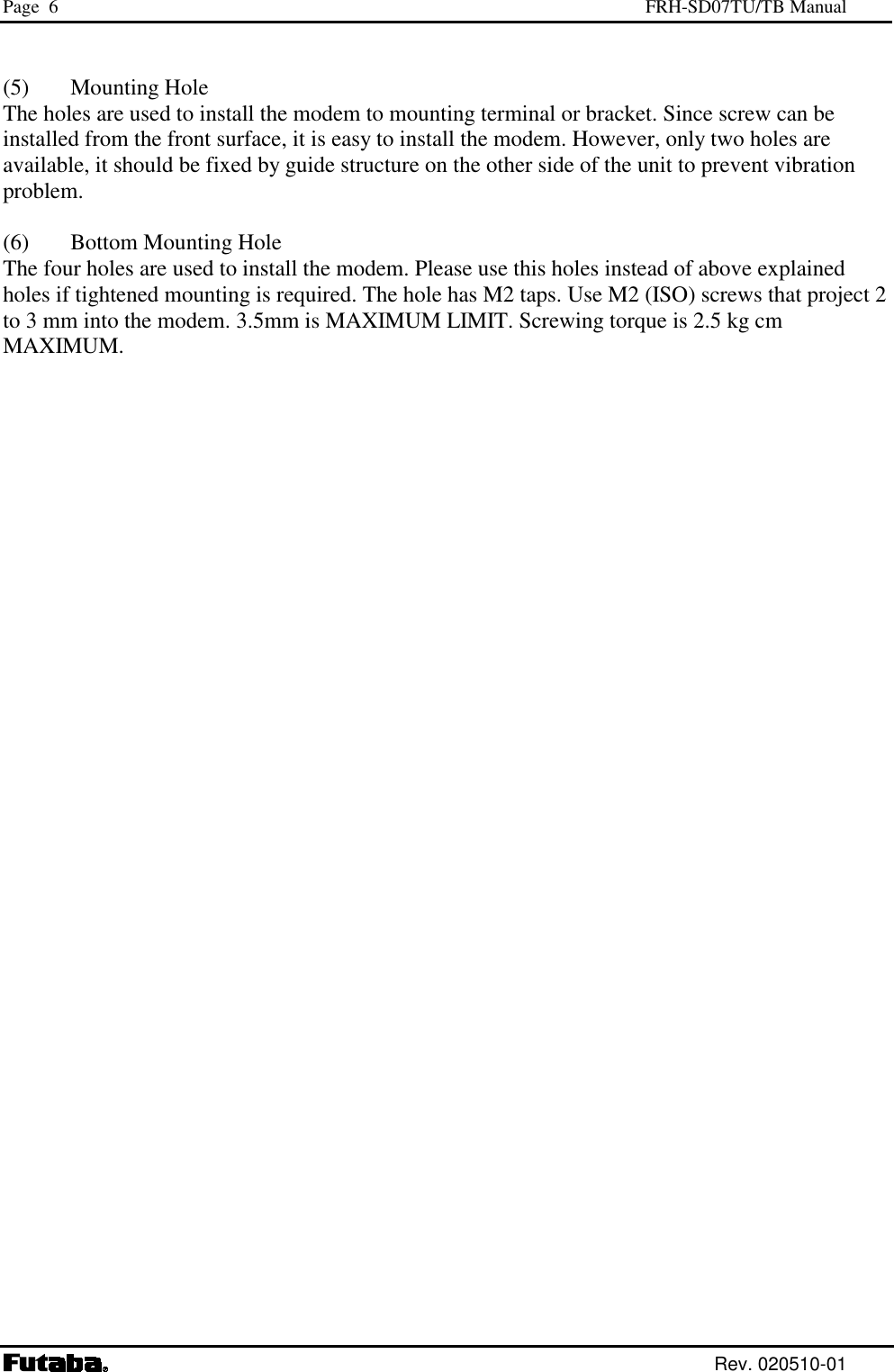
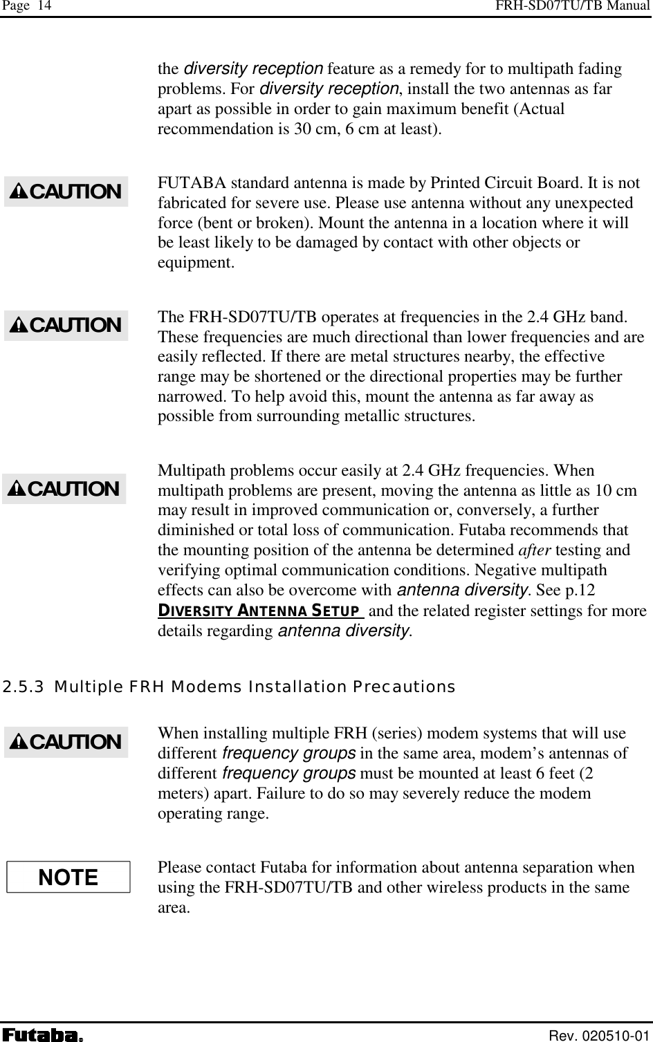
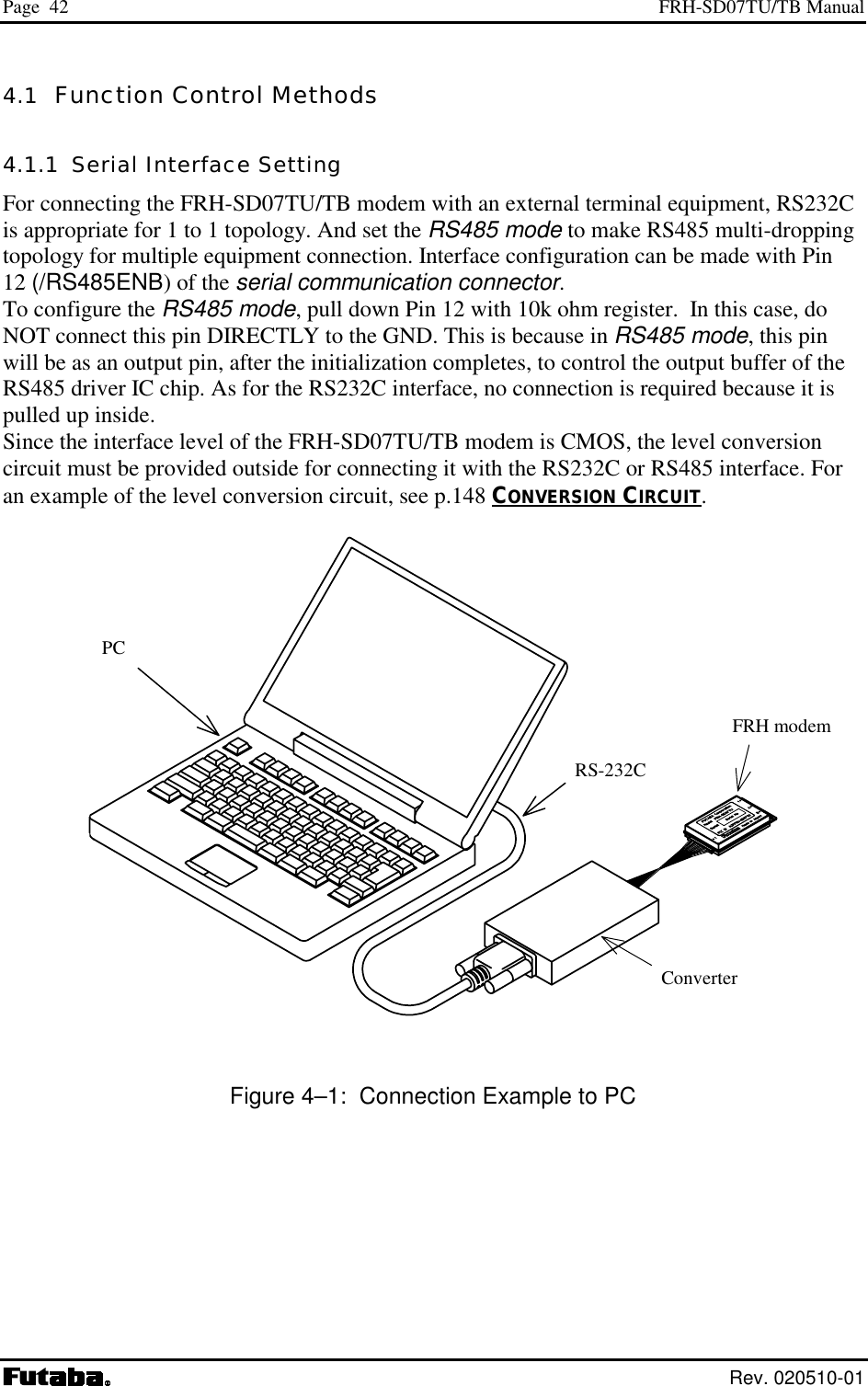
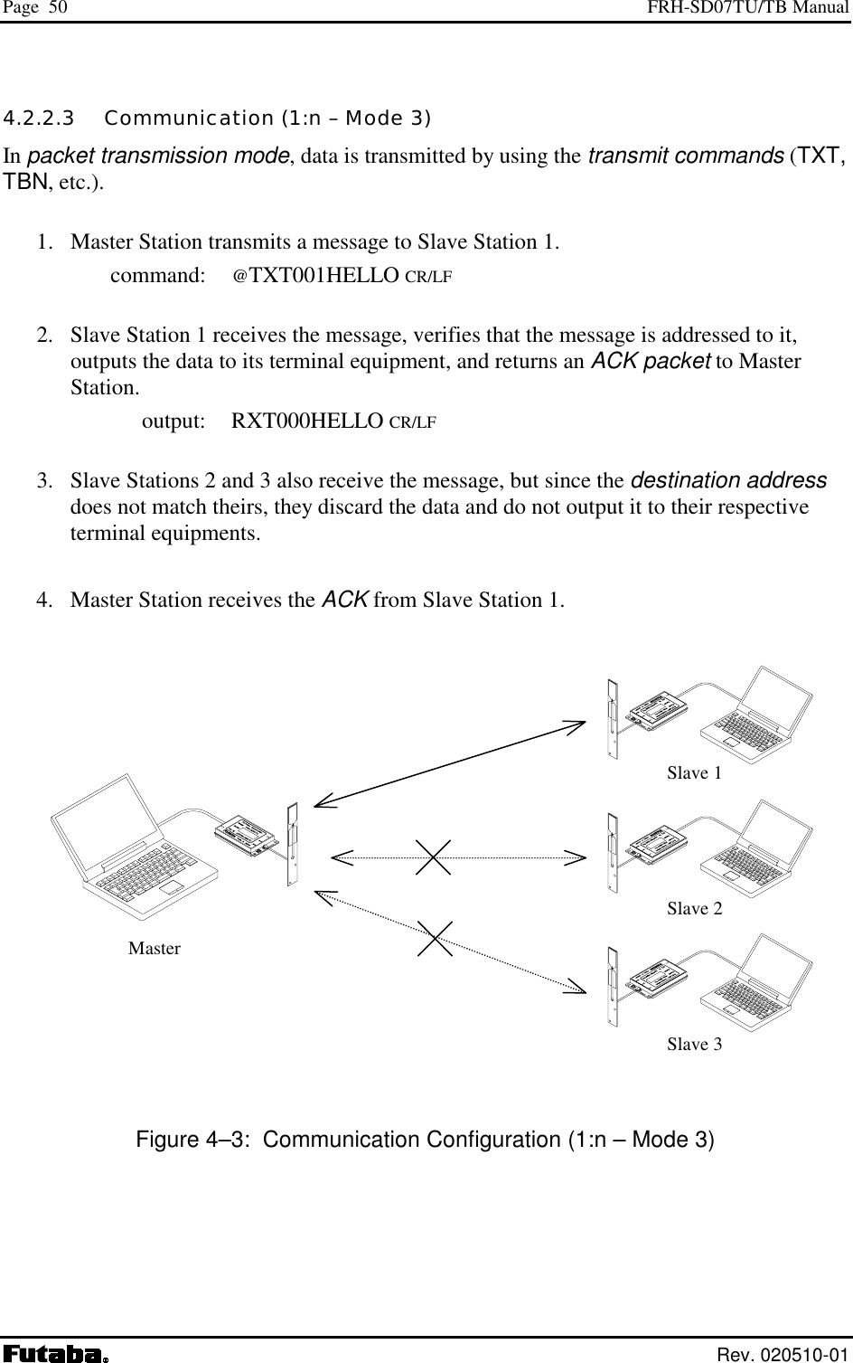
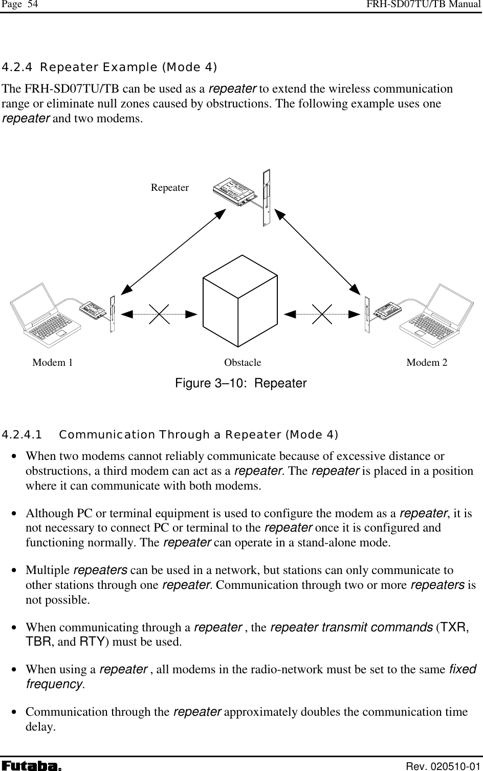
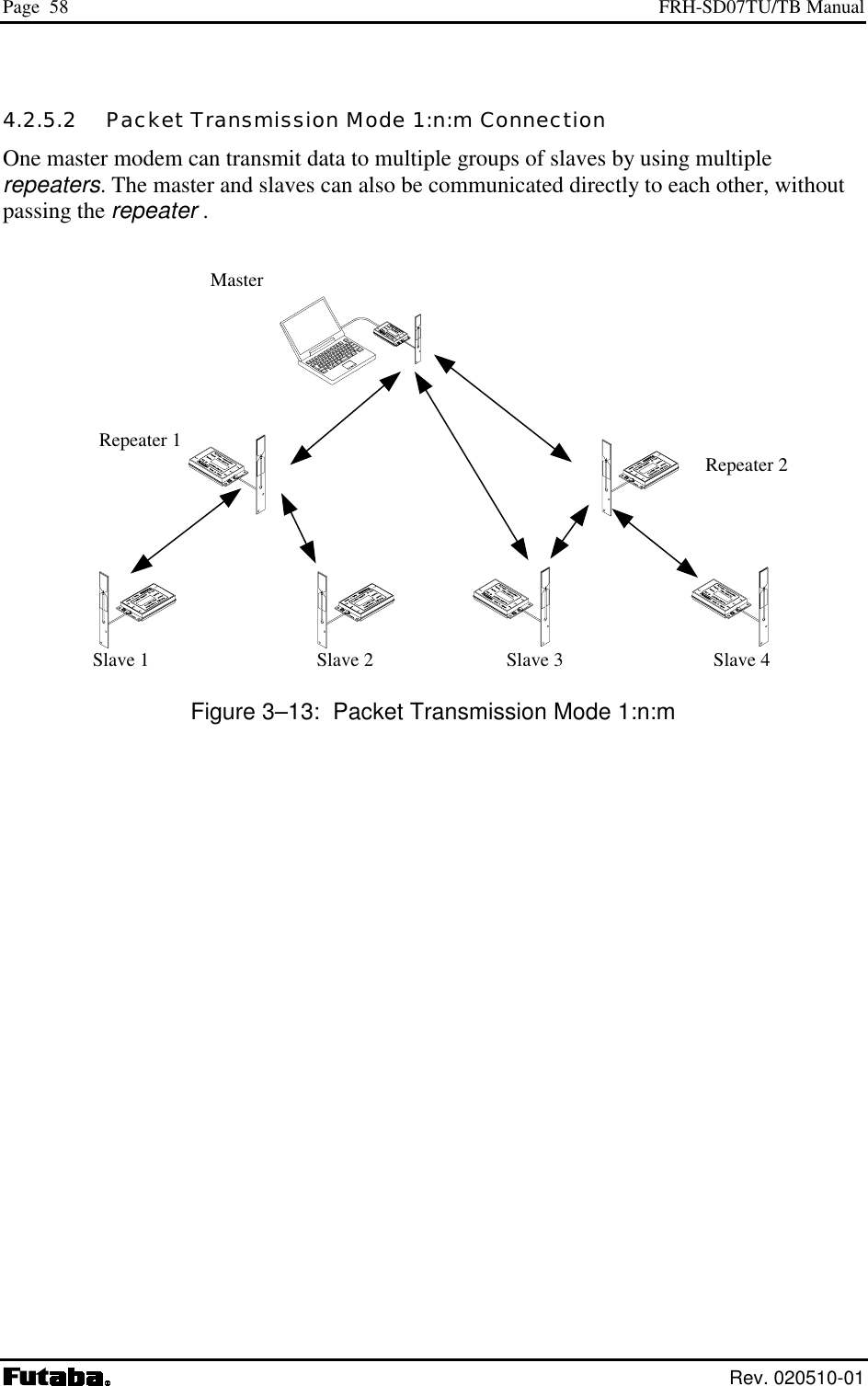
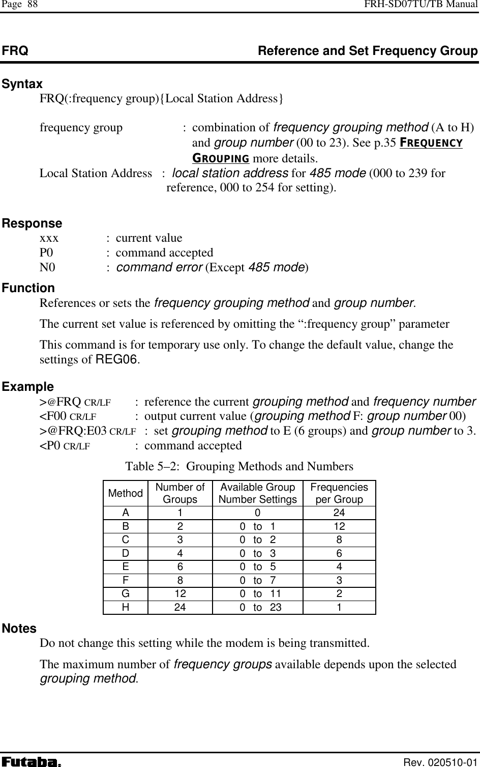
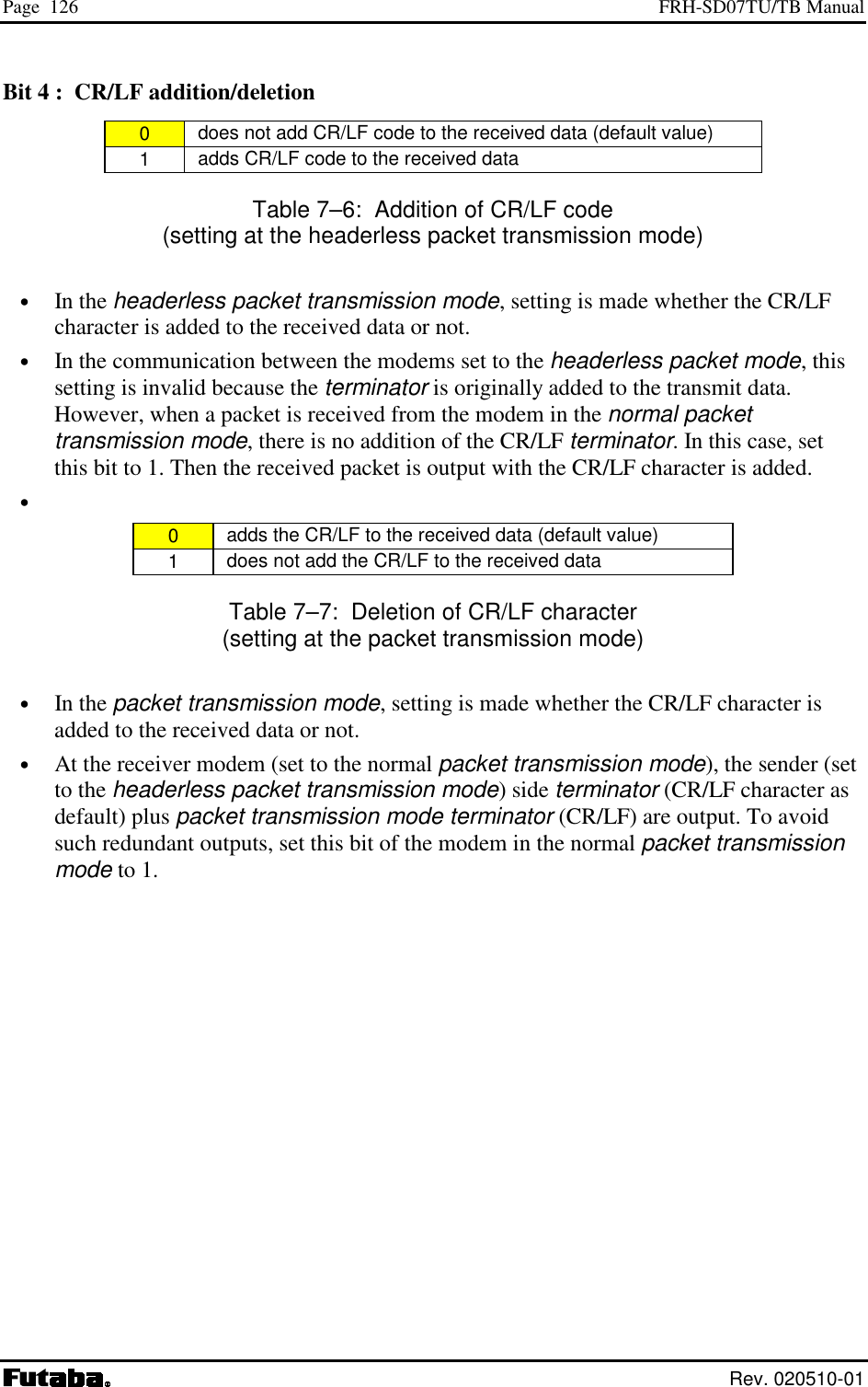
![Page 62 FRH-SD07TU/TB Manual Rev. 020510-01 • Before transmission, radio data packets are scrambled using a pseudo-random data sequence generated with this ID code as the seed. During reception, the original data is restored by de-scrambling it with the pseudo-random data sequence. The modems with different ID codes cannot communicate with each other. REG05: ID Code 2 [default value: 00H] • Used with ID code 1 (REG04), set the ID code. Valid values are 000 to 239. Together with ID code 1, up to 61,440 ID codes can be set. • Do not set the value 240 and above. If excess value is set, the modem ignores the REG04 and REG05 value and assigns REG04 to 255 and REG05 to 239. • In case plural modems are used as a single system, always set the same ID code for all modems and repeaters. REG06: Frequency Group [default value: A0H] • Refer to p.35 FREQUENCY GROUPING in Section 3, for a detailed description of the frequency operation modes. Bits 7 – 5: Grouping of frequency Grouping Setting Bit 7 Bit 6 Bit 5 A 24 freq. × 1 group 0 0 0 B 12 freq. × 2 group 0 0 1 C 8 freq. × 3 group 0 1 0 D 6 freq. × 4 group 0 1 1 E 4 freq. × 6 group 1 0 0 F 3 freq. × 8 group 1 0 1 G 2 freq. ×12 group 1 1 0 H 1 freq. ×24 group 1 1 1 Table 5–2: Grouping of Frequency • Set the grouping method for the 24 available frequencies. The number of available frequencies per group is allocated to perform multi-access in the frequencies of group. • The multi-access function is performed within a frequency group. • When more frequencies per group are made available for multi-access function, the system will gain an advantage in overcoming interference and fading, but average time required to establish a connection will increase because more frequencies are scanned.](https://usermanual.wiki/Futaba/FRH-SD07TU.Users-Manual/User-Guide-251104-Page-78.png)
![Page 63 Futaba Corporation Rev. 020510-01 Bits 4 – 0: Group Number Group No. Bit 4 Bit 3 Bit 2 Bit 1 Bit 0 0 0 0 0 0 0 1 0 0 0 0 1 2 0 0 0 1 0 3 0 0 0 1 1 4 0 0 1 0 0 : : : : : : : : : : : : 19 1 0 0 1 1 20 1 0 1 0 0 21 1 0 1 0 1 22 1 0 1 1 0 23 1 0 1 1 1 Table 5–3: Frequency Group Settings • The frequency group number is set. Valid group numbers for setting vary depending on the frequency grouping method. REG07: RS485 Packet Interval [default value: 05H] • In the packet transmission mode with the RS485 mode is used, sets the interval between response and/or received data which output from the modem to RS485 line. • Be able to set 0 to 254 ms at increment of 1 ms. 255ms is not allowed. The default value is 5 ms. • Set this interval to a larger value than the receiving interval set by REG14. • Suitable setting of this interval avoids the data collision possibility of RS485 line. For details, refer to p.31 COLLISION AVOIDANCE IN RS485 INTERFACE. REG08: Reserved [default value: 11H] • The FRH-SD07TU/TB does not use this register. Keep the default value as it is. REG09: Reserved [default value: 13H] • The FRH-SD07TU/TB does not use this register. Keep the default value as it is. REG10: Command Header [default value: 40H] • Sets the character that identifies the start of a command. • The default is character “@” (40H).](https://usermanual.wiki/Futaba/FRH-SD07TU.Users-Manual/User-Guide-251104-Page-79.png)
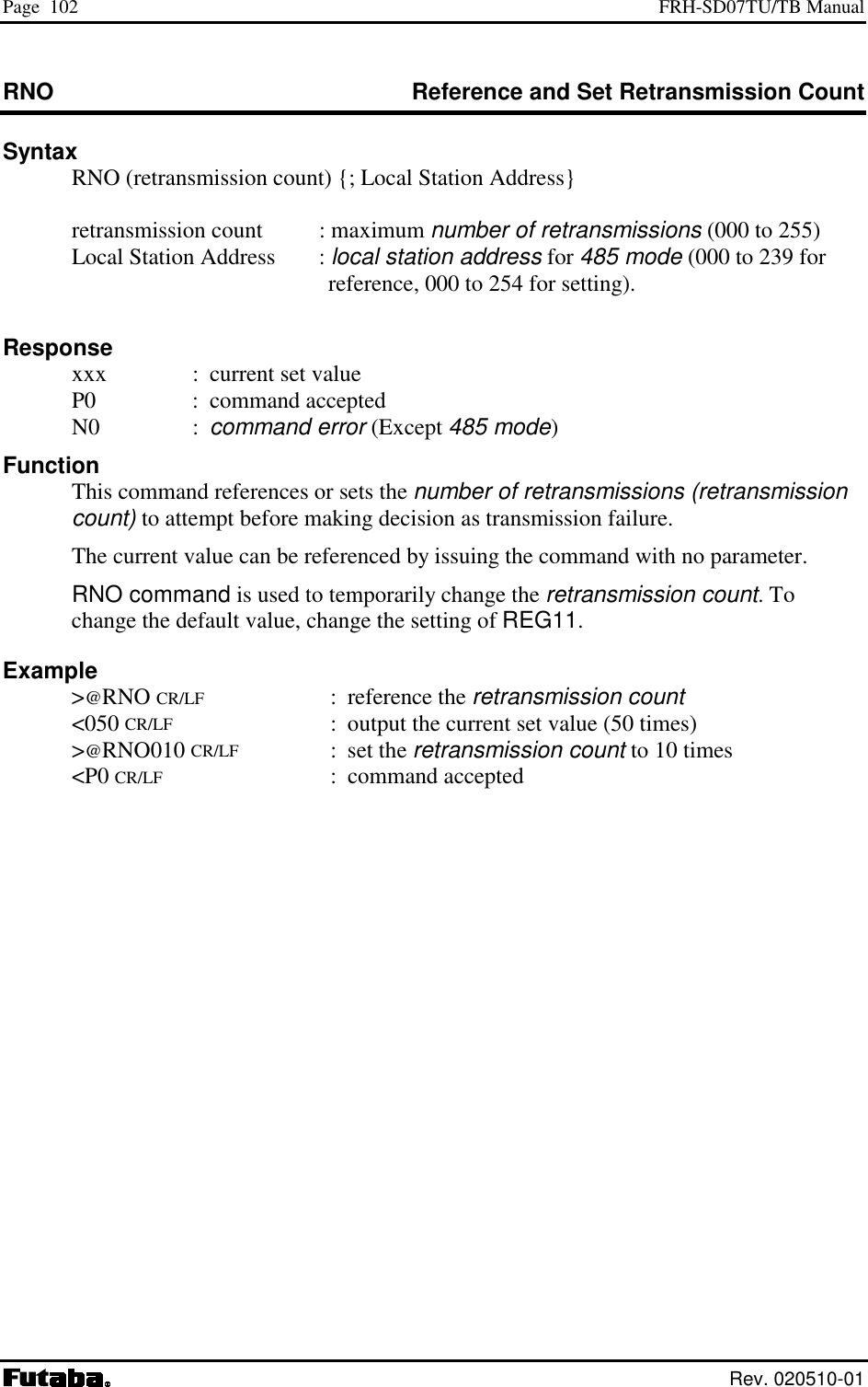
![Page 64 FRH-SD07TU/TB Manual Rev. 020510-01 • When this character is input from the terminal equipment after no character is received for the command recognition interval (REG15) or longer, subsequent input character is recognized as a command for the modem. REG11: Retransmission Count [default value: 32H] • Sets the maximum number of packet retransmission attempts. Valid values are 000 to 254. 255 is not allowed. • When retransmission exceeds the retransmission count (retransmission count plus one for broadcast transmission), the modem outputs an error response to the terminal equipment. REG12: Roaming Threshold [default value: B4H] • At the time to set the frequency roaming (REG19:bit 2 is 1), set the receiving strength threshold of the radio beacon which starts scanning frequency. • Set the value of the desired radio beacon strength threshold represented in dBm excluding the minus sign, e.g., set to “80” to search the next master station when the radio beacon strength becomes below –80 dBm. REG13: Reserved [default value: 1EH] • The FRH-SD07TU/TB does not use this register. Keep the default value as it is. REG14: Receive Data Output Interval [default value: 00H] • Sets the minimum time interval between characters (time from the stop bit of one character to the start bit of the next character) when outputting data from the modem to the terminal equipment. • Valid values are 000 to 255, representing milliseconds in 1 ms increments. • Since the modem transmit data to other end modem in packet form, minimal interval between the character output to the terminal equipment does not guaranteed. Characters are continuously sent to the terminal equipment until the modem’s buffer becomes empty. When the data cannot be received by the terminal equipment, set this interval longer. REG15: Command Recognition Interval [default value: 00H] • When a message data contains a command header character (in case of binary data or data in two-byte Chinese characters), data following the command header character will be interpreted as a command, the message does not transmit properly.](https://usermanual.wiki/Futaba/FRH-SD07TU.Users-Manual/User-Guide-251104-Page-80.png)
![Page 65 Futaba Corporation Rev. 020510-01 • Sets the necessary vacant duration time interval to discriminate between ordinary data character and a command header character. Input a command after a longer interval than time interval setting. • Valid values are 0.1 to 25.4 sec., representing tenths of seconds in 0.1 second increments. (Set an integer value equal to ten times the number of seconds desired.) • When set to 000, the command header is recognized at any time, and when set to 255, all command header character are ignored. REG16: Command Input Timeout [default value: 32H] • Sets the character input timeout interval for command input. It is used as the timeout between the command header and the character following it and between each character of the command. • At the timeout, the modem operation transits from command-input-wait-state to ordinary-data-wait-state. • Valid values are 000 to 255, representing tenths of seconds in 0.1 second increments. (Set an integer value equal to ten times the number of seconds desired.) • A setting of 000 disables this timeout function. REG17: Reserved [default value: 32H] • The FRH-SD07TU/TB does not use this register. Keep the default value as it is.](https://usermanual.wiki/Futaba/FRH-SD07TU.Users-Manual/User-Guide-251104-Page-81.png)
![Page 66 FRH-SD07TU/TB Manual Rev. 020510-01 REG18: Communication Setting 1 [default value: 8CH] Bits 7 – 2: Reserved • The FRH-SD07TU/TB does not use this register. Keep the default value as it is. Bit 1: Source address check 0 Inhibit source address checking (default value) 1 Activate source address checking Table 5–4: Source Address Check Settings • When the source address checking is active and the source address in the received packet header does not match the destination address setting (REG02), the data is discarded (data cannot be received). Bit 0: Destination address check 0 Inhibit destination address checking on receipt (default) 1 Activate destination address checking on receipt Table 5–5: Destination address check • When the destination address checking is active and the destination address in the received packet header does not match the received modem’s local station address (REG00), the data is discarded (data cannot be received).](https://usermanual.wiki/Futaba/FRH-SD07TU.Users-Manual/User-Guide-251104-Page-82.png)
![Page 67 Futaba Corporation Rev. 020510-01 REG19: Communication Setting 2 [default value: 00H] Bit 7: Reserved • The FRH-SD07TU/TB does not use this register. Keep the default value as it is. Bit 6: Diversity Reception 0 Disable diversity reception (default value) 1 Enable diversity reception Table 5–6: Diversity Reception Settings • Enable/disable diversity reception. • To enable diversity reception, set this bit to 1 and connect an antenna to Antenna Terminal B. • Enabling diversity reception with only one antenna connected may degrade the reception performance. Bit 5: Broadcast Transmission Reception 0 Enable broadcast transmission reception (default value) 1 Disable broadcast transmission reception Table 5–7: Broadcast Reception Settings • Enable/disable reception of broadcast transmission in packet transmission mode (Mode 3 and 5). Bit 4: Antenna selection 0 Receiving antenna is fixed to A (default value) 1 Receiving antenna is fixed to B Table 5–8: Antenna Selection • At the non-diversity reception, decide the antenna terminal for the receiving antenna fixing. • Selection of 1 fixes the receiving antenna to the terminal B. When the high gain antenna connecting to the terminal B is used for reception, this setting would achieve better performance than the diversity reception in some case.](https://usermanual.wiki/Futaba/FRH-SD07TU.Users-Manual/User-Guide-251104-Page-83.png)
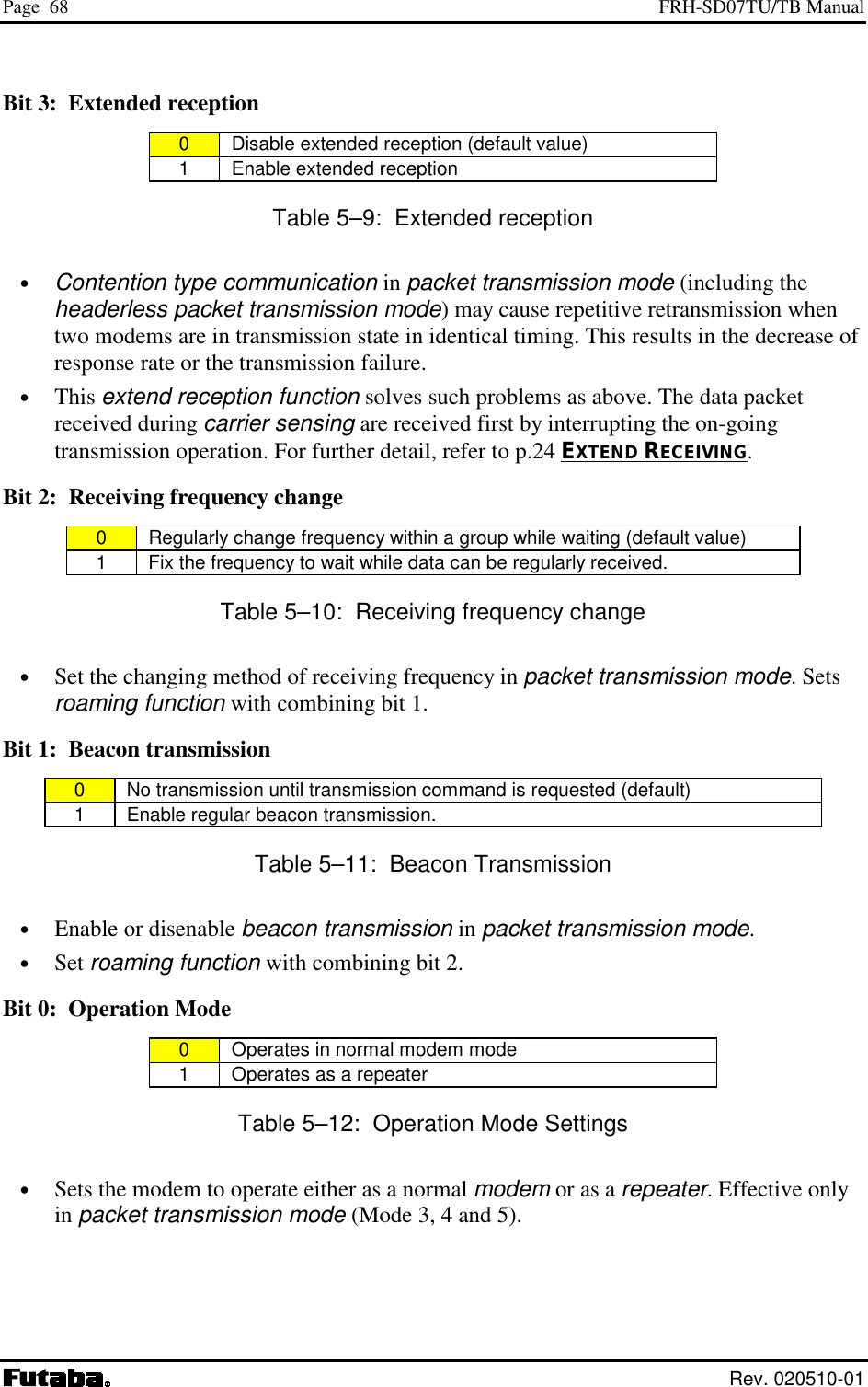
![Page 69 Futaba Corporation Rev. 020510-01 REG20: RS-232C Setting 1 [default value: 05H] Bit 7: Data Length 0 8 bit data bytes (default value) 1 7 bit data bytes Table 5–13: Data Length Settings Bit 6: Parity Bit 0 No parity bit (default value) 1 Parity bit Table 5–14: Parity Settings Bit 5: Even/Odd Parity 0 Even parity (default value) 1 Odd parity Table 5–15: Odd/Even Parity Settings • Invalid when bit 6 is set to 0, without parity. Bit 4: Stop Bit 0 1 stop bit (default value) 1 2 stop bits Table 5–16: Stop Bit Settings](https://usermanual.wiki/Futaba/FRH-SD07TU.Users-Manual/User-Guide-251104-Page-85.png)
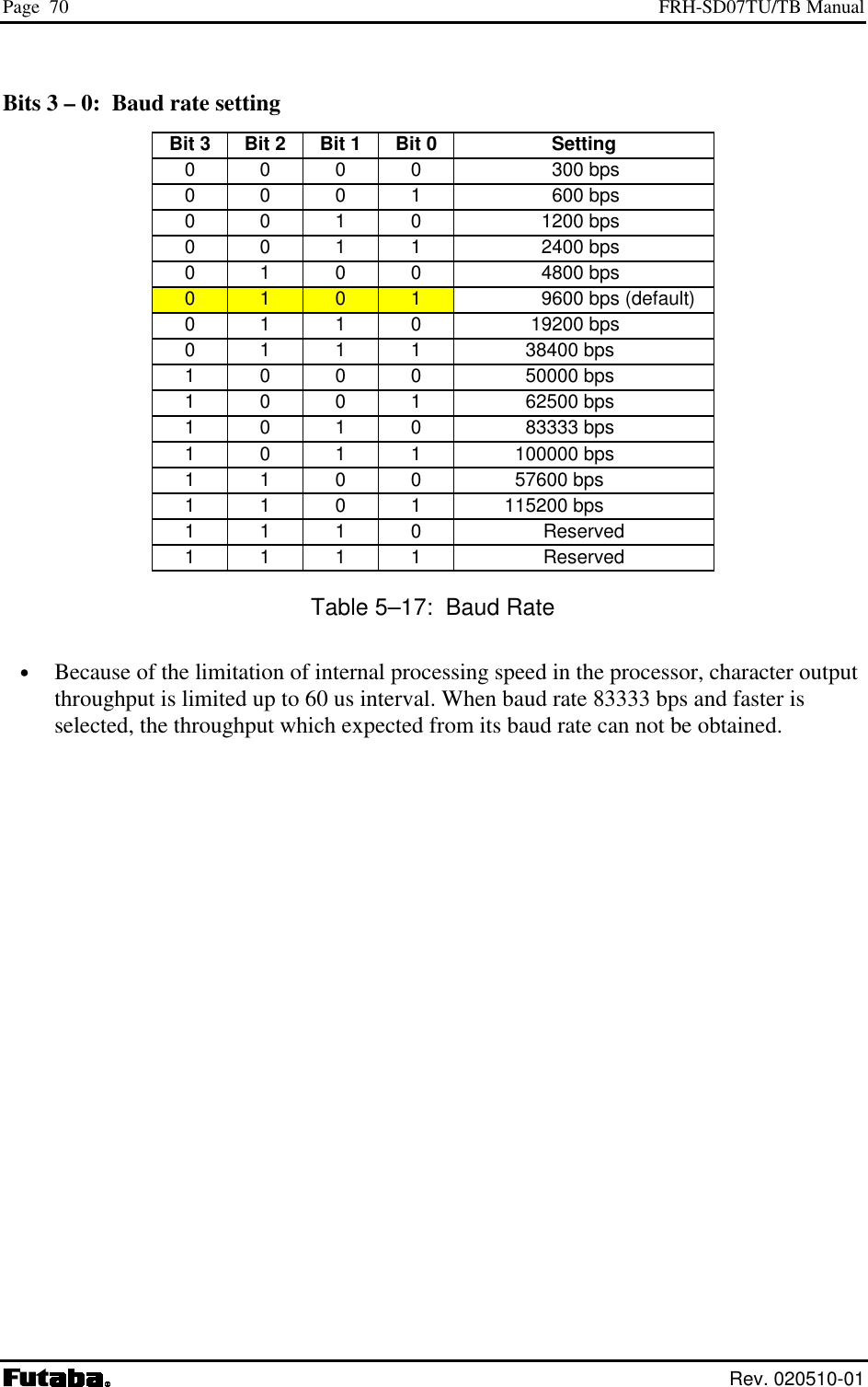
![Page 71 Futaba Corporation Rev. 020510-01 REG21: RS-232C Setting 2 [default value: 09H] Bits 7 – 2: Reserved • The FRH-SD07TU/TB does not use this register. Keep the default value as it is. Bit 1: Flow Control 0 No flow control (default value) 1 Hardware flow control Table 5–18 Software/Hardware Flow Control Settings • Selects the flow control method. This setting must match the connected terminal equipment’s setting. • Hardware flow control uses the two control lines RTS and CTS. When using hardware flow control, be sure that RTS and CTS lines are properly wired. • When using with the RS485 interface, be sure to set to 0. Bit 0: Reserved • The FRH-SD07TU/TB does not use this register. Keep the default value as it is.](https://usermanual.wiki/Futaba/FRH-SD07TU.Users-Manual/User-Guide-251104-Page-87.png)
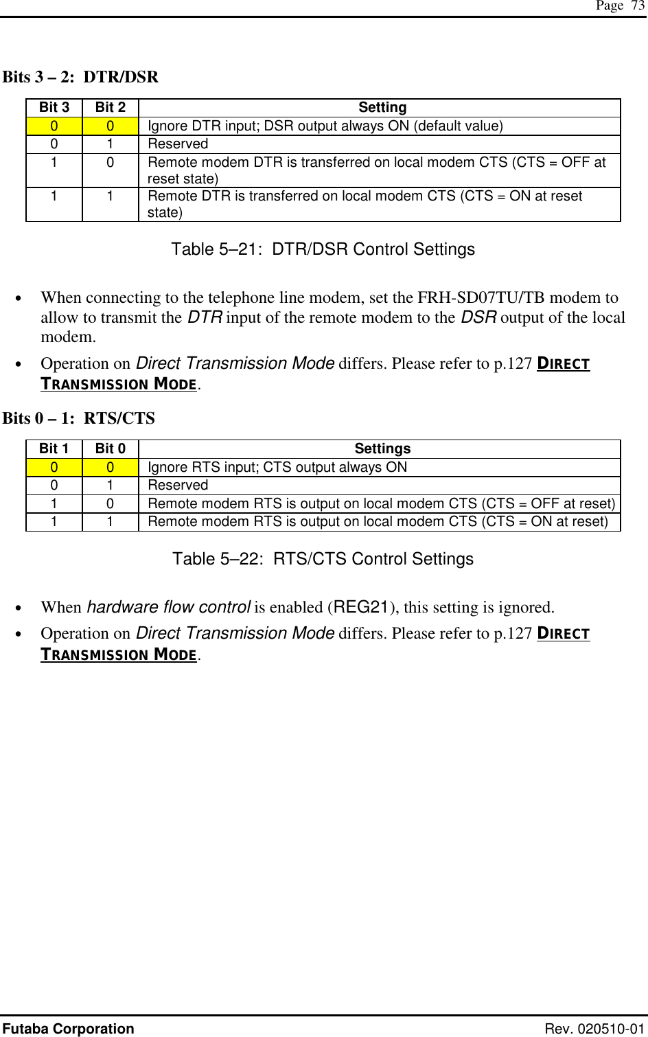
![Page 72 FRH-SD07TU/TB Manual Rev. 020510-01 REG22: RS-232C Setting 3 [default value: 00H] Bit 7: Enable and Disable Reception 0 Enable reception at the initial state (default value) 1 Disable reception at the initial state Table 5–19: Enable/Disable Reception • Select enable or disable reception at the initial state in the packet transmission mode. • The initial state is in reception enable. Depending on an usage of the modem, the initial state of the modem may be better in the reception disable state. In such a case, use this setting. • Issue the REN command to enable reception. Bit 6: Reserved • The FRH-SD07TU/TB does not use this register. Keep the default value as it is. Bits 5 – 4: DCD (Data Carrier Detect) Bit 5 Bit 4 Setting 0 0 Ignore DCD input; DCD output always ON (default value) 0 1 Reserved 1 0 Remote modem’s DCD (IN) is transferred to local modem DCD (OUT). (DCD Output = OFF at reset state) 1 1 Remote modem’s DCD (IN) is transferred to local modem DCD (OUT) (DCD Output = ON at reset state) Table 5–20: DCD Settings • When connecting to the telephone line modem, set the FRH-SD07TU/TB modem to transfer the DCD input of the remote modem to the DCD output of the local modem. • Operation on Direct Transmission Mode differs. Please refer to p.127 DIRECT TRANSMISSION MODE.](https://usermanual.wiki/Futaba/FRH-SD07TU.Users-Manual/User-Guide-251104-Page-88.png)
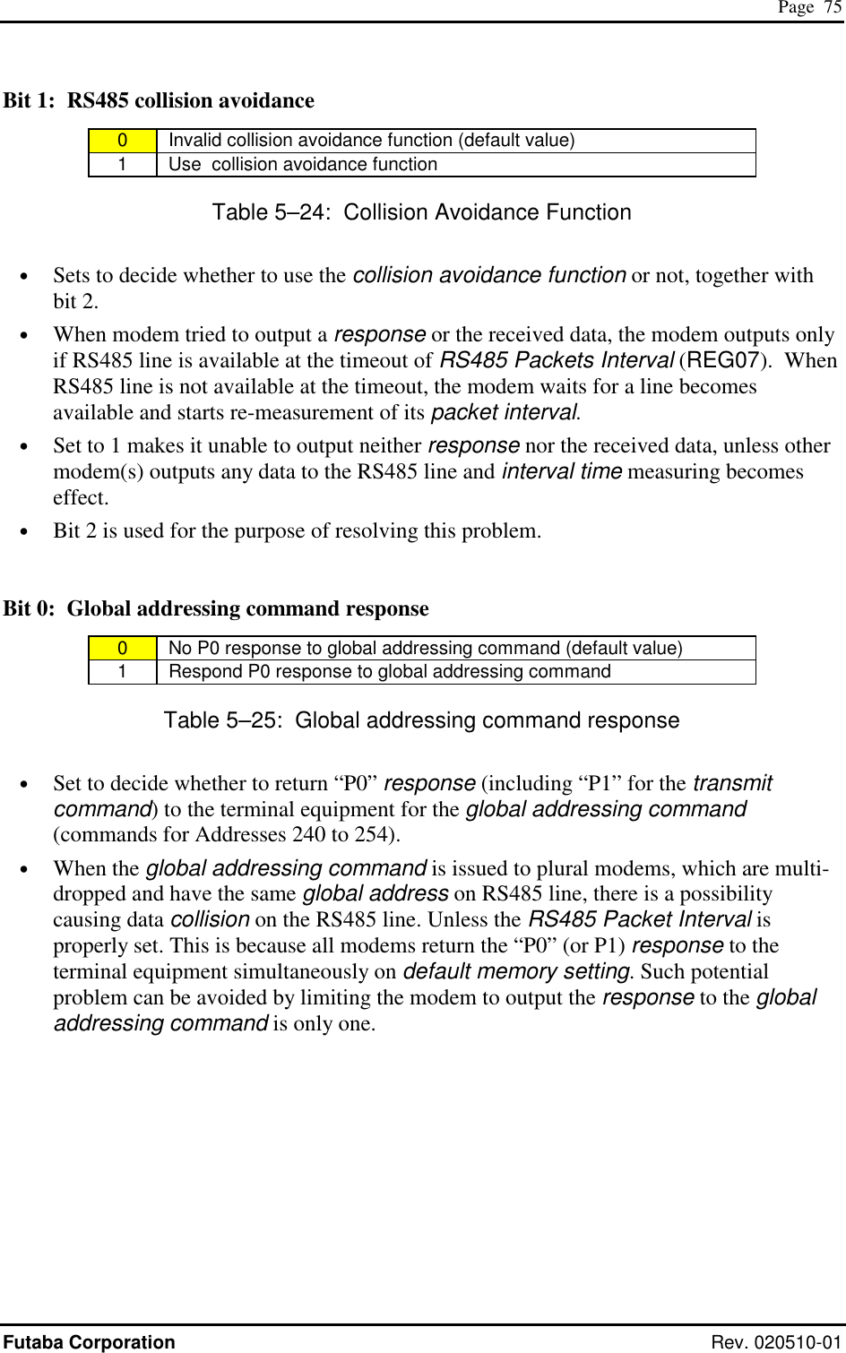
![Page 74 FRH-SD07TU/TB Manual Rev. 020510-01 REG23: Miscellaneous Settings [default value: 00H] Bit 7 – 5: reserved • The FRH-SD07TU/TB does not use this register. Keep the default value as it is. Bit 4 : CR/LF addition/deletion • Especially used for the headerless packet transmission mode only. Refer to p.124 MEMORY REGISTER SETTING, IN HEADERLESS PACKET TRANSMISSION MODE. Bit 3: reserved • The FRH-SD07TU/TB does not use this register. Keep the default value as it is. Bit 2: RS485 collision avoidance regular interval output 0 No C/R code output for collision avoidance (default value) 1 Regularly output C/R code for collision avoidance Table 5–23: C/R Code Regular Interval Output • Sets whether the collision avoidance function is used or not, together with bit 1. • When this bit is set to 1, responses or data will be output to RS485 line if there are such responses or data exist in the buffer at the timeout of the RS485 Packet Interval (REG07). If there are no such responses or data exist in the buffer, the C/R code (0Dh) is compulsorily output. • The effective use of this function helps to shift the output timing of multi-dropped modems on RS485 line. Eventually it avoids the data collision on the RS485 line. • To use this function, set REG23:bit 1 of all RS485 multi-dropped modems to 1. And set all the RS485 Packet Interval (REG07) to different values more than 1.5 bytes each. Further set this bit of the modem, the RS485 Packet Interval is set to the longest, to 1.](https://usermanual.wiki/Futaba/FRH-SD07TU.Users-Manual/User-Guide-251104-Page-90.png)
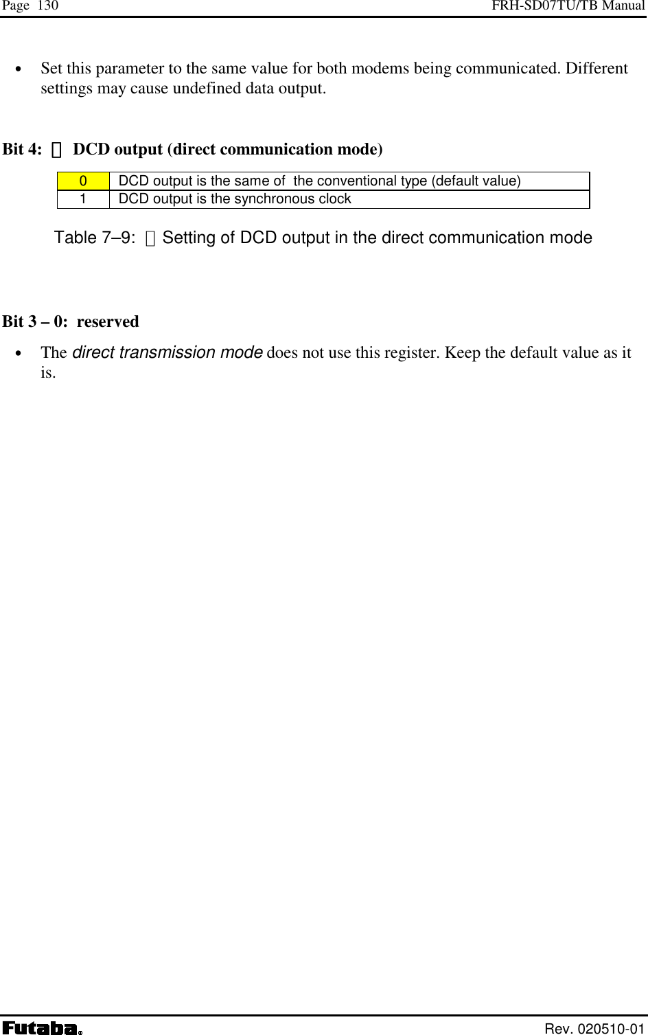
![Page 76 FRH-SD07TU/TB Manual Rev. 020510-01 REG24: Special Mode Settings [default value: C0H] Bit 7 – 6: reserved • The FRH-SD07TU/TB does not use this register. Keep the default value as it is. Bit 5: Delay time of transmission and reception (Direct transmission mode) 0 Same delay time as the conventional series modem (default value) 1 Sets short delay time Table 5–26: Setting of delay time of transmission and reception • Sets the delay time of the direct transmission mode using REG03 together. For details, refer to p.127 DIRECT TRANSMISSION MODE Bit 4: DCD output((((Direct transmission mode)))) 0 DCD outputs in the same way as the conventional series modem. (default value) 1 DCD acts as the synchronous clock output. Table 5–27: Output of DCD direct transmission mode setting • Sets the direct transmission mode using REG03 together. For details, refer to p.127 DIRECT TRANSMISSION MODE. Bit 3 – 0: reserved • The FRH-SD07TU/TB does not use this register. Keep the default value as it is.](https://usermanual.wiki/Futaba/FRH-SD07TU.Users-Manual/User-Guide-251104-Page-92.png)
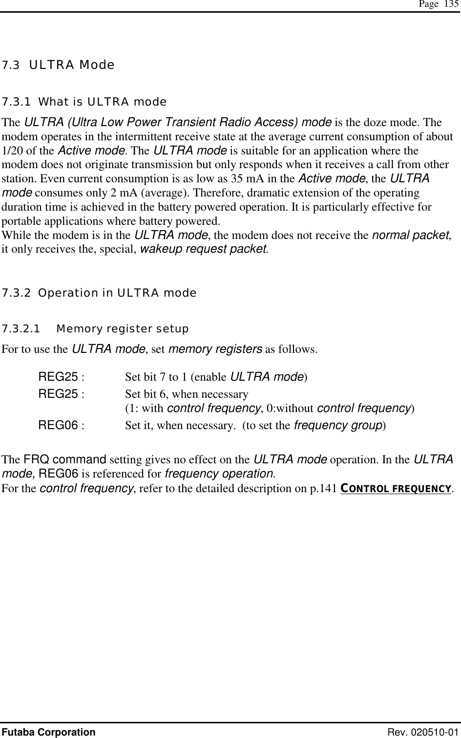
![Page 77 Futaba Corporation Rev. 020510-01 REG25: ULTRA Mode Settings [default value: 40H] Bit 7: ULTRA mode setting 0 Disable ULTRA mode (default value) 1 Enable ULTRA mode Table 5–28: ULTRA mode setting Bit 6: ULTRA mode control frequency channel setting 0 No control channel is used 1 Use control channel (default value) Table 5–29: Control frequency channel setting • Sets the frequency to be wait-to-receive in the ULTRA mode. When the control frequency is assigned, the lowest frequency of the frequency group is used as the control frequency. For details, refer to p.141 CONTROL FREQUENCY. Bit 5 – 0: reserved • The FRH-SD07TU/TB does not use this register. Keep the default value as it is. REG26: Reserved [default value: 00H] • The FRH-SD07TU/TB does not use this register. Keep the default value as it is.](https://usermanual.wiki/Futaba/FRH-SD07TU.Users-Manual/User-Guide-251104-Page-93.png)
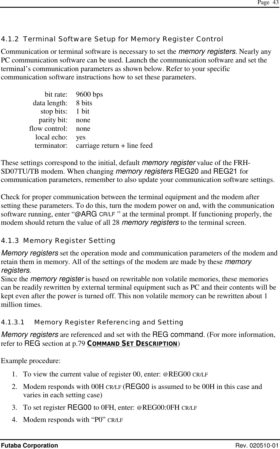
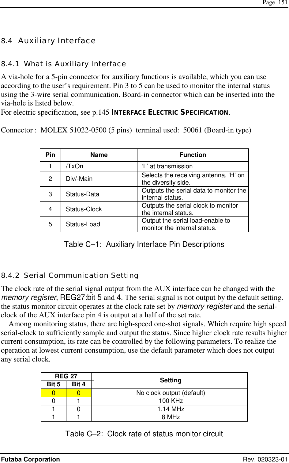
![Page 78 FRH-SD07TU/TB Manual Rev. 020510-01 REG27: Frequency Band Settings [default value: 01H] Bit 7 – 6: reserved • The FRH-SD07TU/TB does not use this register. Keep the default value as it is. Bit 5 – 4: Output clock rate of AUX terminal Bit 5 Bit 4 Setting 0 0 No clock output (default value) 0 1 100KHz 1 0 1.14MHz 1 1 8MHz Table 5–30: Setting of output clock rate of AUX terminal • Sets the operation clock rate of the output signal of the AUX terminal for the status monitor use. Some of the status data contains high speed one-shot signals, which requires high speed clock to properly catch. Because of higher current consumption when higher clock rate, this parameter controls the clock rate to decrease current consumption. • For the function of the AUX terminal, refer to p.151 AUXILIARY INTERFACE. Bit 3 – 0: Frequency band setting Bit 3 Bit 2 Bit 1 Bit 0 Setting 0 0 0 0 Invalid (forced to 0001) 0 0 0 1 2433-2479MHz (default value) 0 0 1 0 Do not set (Invalid) 0 0 1 1 01 Band 0 1 0 0 02 Band 0 1 0 1 2420-2466MHz 2MHz Separation 0 1 1 0 2423-2469MHz 2MHz Separation 0 1 1 1 Reserved 1 - - - Table 5–31: Frequency band setting • For the frequency band, refer to p.35 FREQUENCY BAND. • For the FRH-SD07TB users in France and Spain, frequency usage is restricted to 02 Band because of its country’s regulatory authority. Also please refer p.35 FREQUENCY BAND. for its details.](https://usermanual.wiki/Futaba/FRH-SD07TU.Users-Manual/User-Guide-251104-Page-94.png)
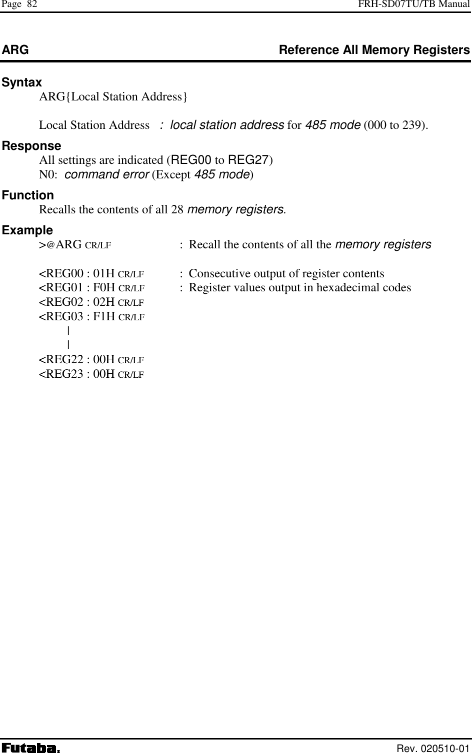
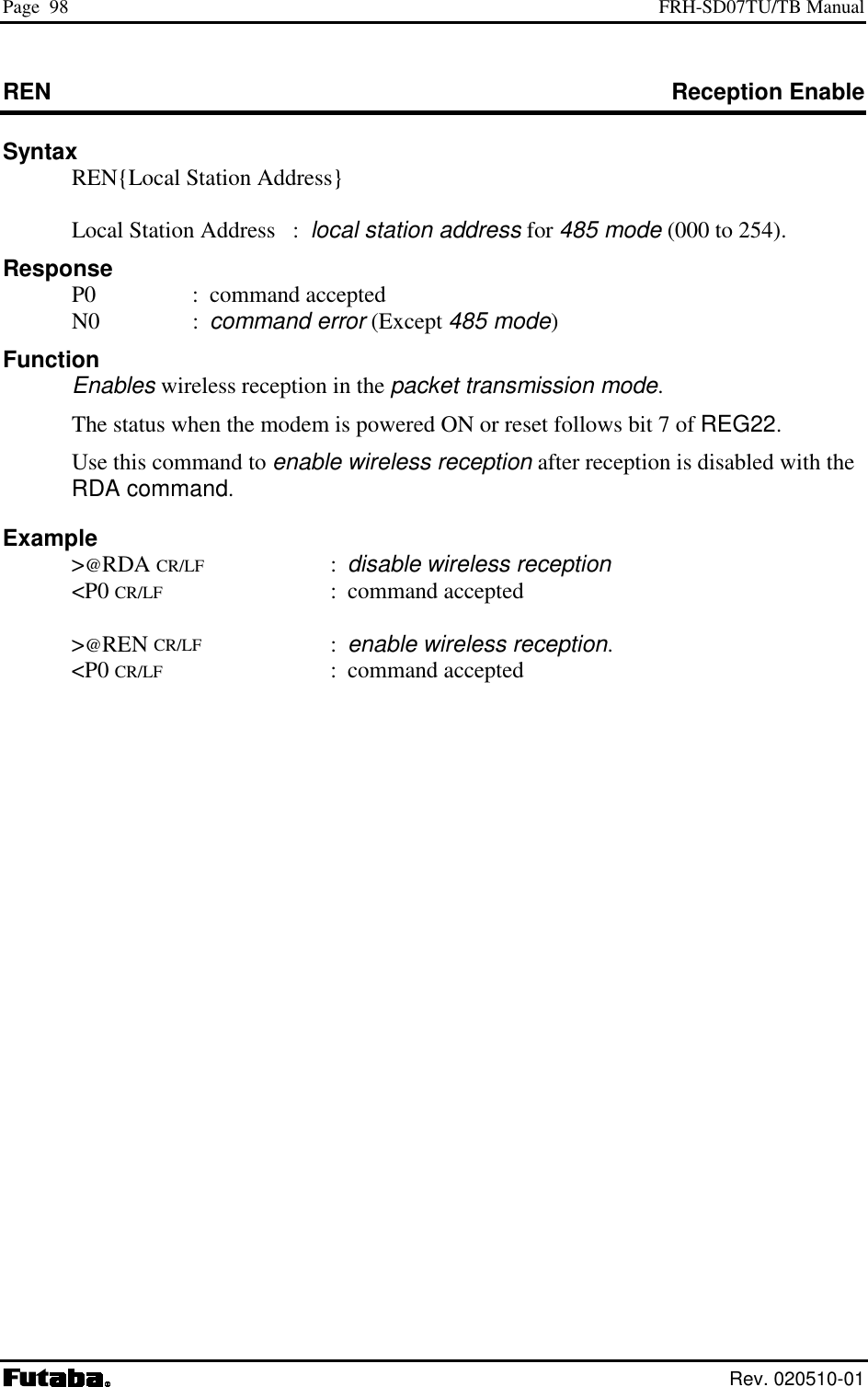
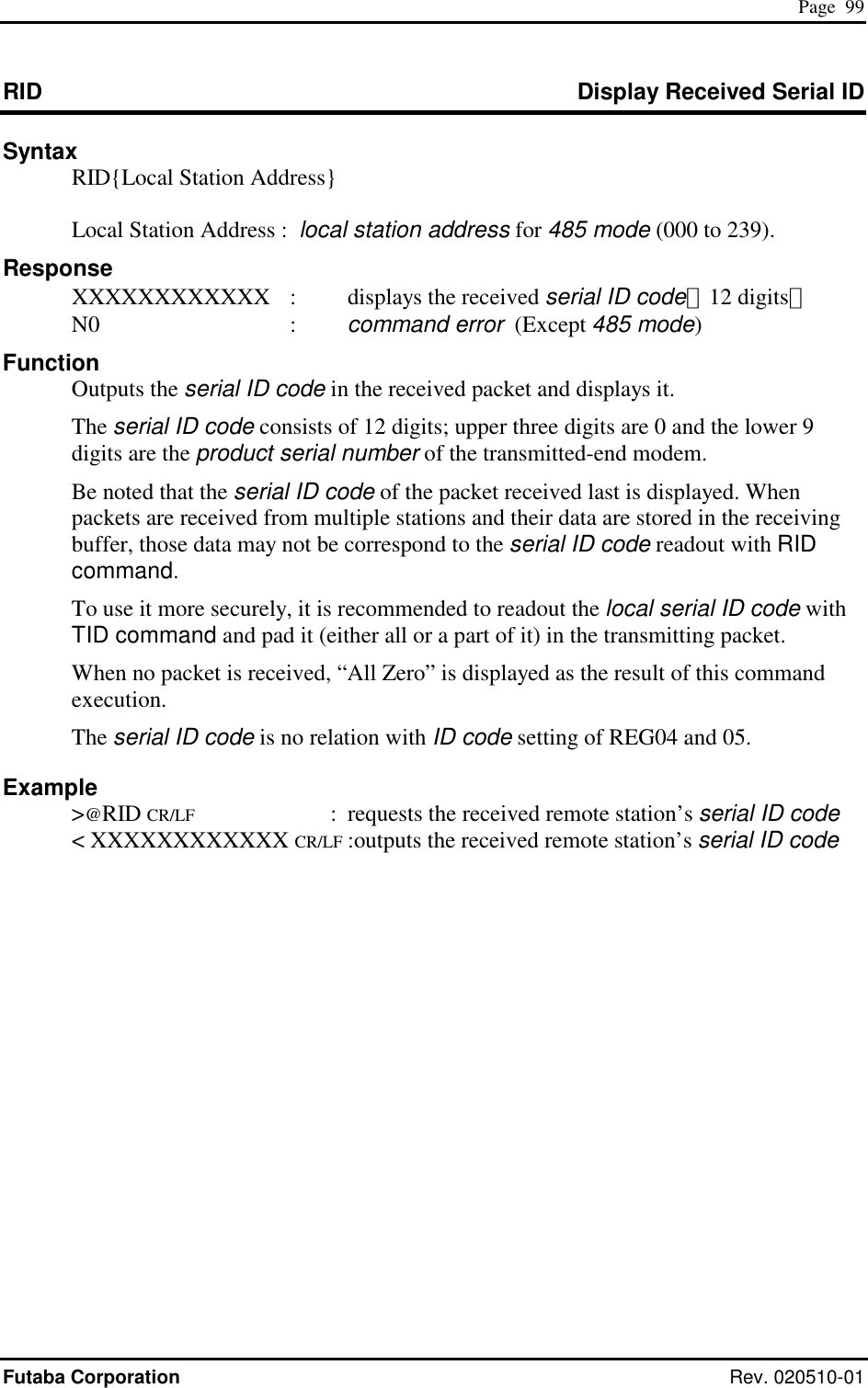
![Page 81 Futaba Corporation Rev. 020510-01 The symbols used in this section have the following meaning: > : Input character from the terminal equipment to the modem < : Output from the modem to the terminal equipment @ : Command header CR/LF : Terminator (carriage return + line feed) [ ] : Required input parameter/s Be sure to input. ( ) : Optional input parameter/s May be omitted {} : 485 mode local station address (REG00). Be sure to input at 485 mode In the Syntax and Response segments of the following command descriptions the terminator symbol (CR/LF) has been omitted for clarity.](https://usermanual.wiki/Futaba/FRH-SD07TU.Users-Manual/User-Guide-251104-Page-97.png)

 {;Local Station Address} register number : register number to be set (00 to 23) value : value to be set. Input 2 hexadecimal digits (0 through 9 and A through F) followed by the number radix designator H. Local Station Address : local station address for 485 mode (000 to 239 for reference, 000 to 254 for setting). Response xxH : current value (reference) P0 : command accepted (setting) N0 : command error (Except 485 mode) N6 : memory register write error Function References or sets memory registers. The current register value is referenced by omitting the “value” parameter. Example >@REG00 CR/LF : reference the contents of register 00 <01H CR/LF : displays current value >@REG00 : 02H CR/LF : set value of memory register 00 to 02H (hexadecimal) <P0 CR/LF : command accepted Notes The register can be rewritten sequentially. However, to make its parameter valid after rewriting it, re-supply the power, reset the modem using the Shutdown mode pin (Pin 11 of the serial communication connector) or use RST command. While rewriting the memory register, do not turn off the power until response is output. Otherwise, the memory registers content may be collapsed. When the response of the memory register write error is output, set the values after initializing the memory register.](https://usermanual.wiki/Futaba/FRH-SD07TU.Users-Manual/User-Guide-251104-Page-113.png)
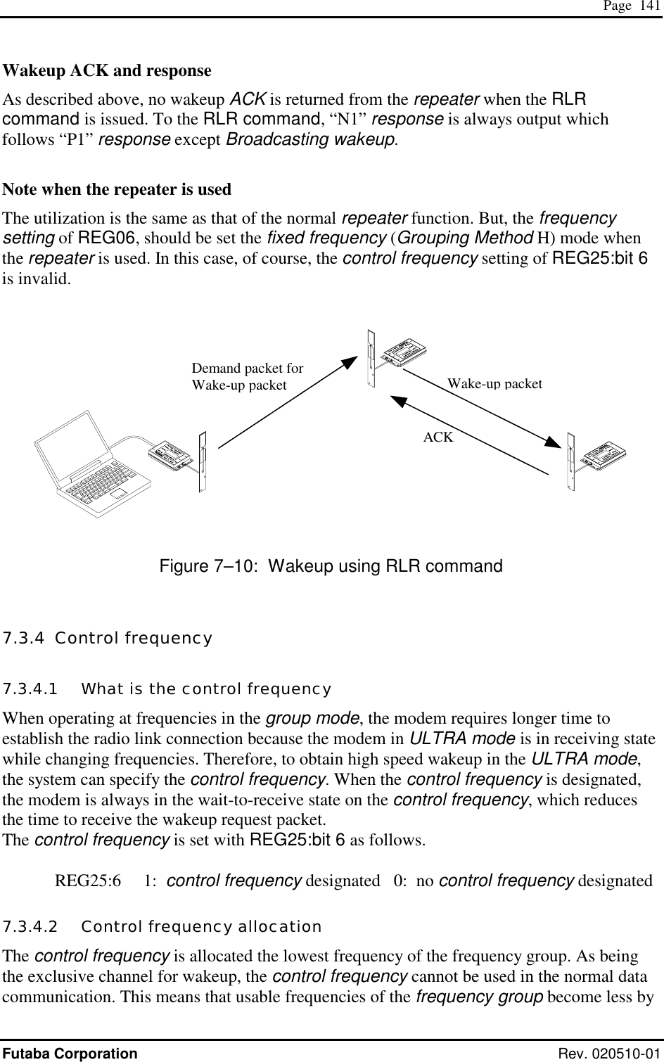
![Page 100 FRH-SD07TU/TB Manual Rev. 020510-01 RLR Release ULTRA Mode Through Repeater Syntax RLR [repeater address] [destination address]{Local Station Address} repeater address : address of repeater to pass through (000 to 239) destination address : address of destination station (000 to 239, set to 255 for broadcast ULTRA mode release) Local Station Address : local station address for 485 mode (000 to 254). Response P1 : command accepted. Transmitting, the request to release the ULTRA mode through the repeater. P0 : Broadcast ULTRA mode release request transmission complete N0 : command error (Except 485 mode) N1 : ULTRA mode release request transmission complete Function Makes the destination station(s) in the ULTRA (Ultra Low-power Transient Radio Access) mode return to the Active mode by transmitting ULTRA wakeup request packet from the repeater. Local modem just send the request to the repeater. At the command completion, “N1” response is output from in any case (P1 to broadcast case). To confirm that the destination station returns to the Active mode, attempt communication with the destination station using TXR command. Example >@RLR100001 CR/LF : transmitting to Station 001 the request to release the ULTRA mode from the repeater 100. <P1 CR/LF : transmitting the Wakeup transmission request signal <N1 CR/LF : request signal transmission completes (unknown whether succeeded or failed) >@ RLR100255 CR/LF : transmits the broadcast request signal to release the ULTRA mode <P1 CR/LF : transmitting the request signal < P0 CR/LF : request signal transmission completes (unknown whether succeeded or failed)](https://usermanual.wiki/Futaba/FRH-SD07TU.Users-Manual/User-Guide-251104-Page-116.png)
![Page 101 Futaba Corporation Rev. 020510-01 RLU Release ULTRA Mode (Direct) Syntax RLU [destination address]{Local Station Address} destination address : address of destination station (000 to 239, set to 255 for all station) to ULTRA mode release Local Station Address : local station address for 485 mode (000 to 254). Response P0 : ULTRA mode successfully released P1 : command received. transmitting the Wakeup request packet of the ULTRA mode N0 : command error (Except 485 mode) N1 : failed in releasing the ULTRA mode (no response from the destination station) Function Makes the destination station(s) in the ULTRA (Ultra Low-power Transient Radio Access) mode return to the Active mode by transmitting Wakeup request packet, ULTRA mode release signal. In case of all station’s ULTRA mode release (broadcast), the modem outputs “P0” response in any case. To confirm that the destination station returns to the Active mode, attempt communication with the destination station using TXT command. When the destination station, its REG 25:bit 7 is set to 1 which allows the ULTRA mode operation, but operating in the Active mode, will return “release success ACK” when it receives the Wakeup request packet , ULTRA mode release signal. Therefore, the response to the RLU command is “P0”. Example >@RLU001 CR/LF : transmitting to Station 001 Wakeup request packet, the request to release the ULTRA mode <P1 CR/LF : transmitting the Wakeup request packet <N1 CR/LF : release failed >@ RLU002 CR/LF : transmits to Station 001 the Wakeup request packet <P1 CR/LF : transmitting the Wakeup request packet <P0 CR/LF : release succeeded >@ RLU255 CR/LF : transmits to all stations Wakeup request packet <P1 CR/LF : transmitting the Wakeup request packet <P0 CR/LF : transmission of Wakeup request packet completes (unknown whether it is succeeded or failed)](https://usermanual.wiki/Futaba/FRH-SD07TU.Users-Manual/User-Guide-251104-Page-117.png)
![Page 105 Futaba Corporation Rev. 020510-01 RPT Retransmit Message Syntax RPT [destination address]{Local Station Address} destination address : address of destination station (000 to 239) set 240 to 254 for global addressed destination set 255 for broadcast transmission Local Station Address : local station address for 485 mode (000 to 254). Response P0 : data transmission succeeded P1 : command accepted, data being transmitted. P2 : data packet reached to repeater N0 : command error (Except 485 mode) N1 : data transmission failed -- no response from destination station N2 : data transmission failed -- destination station is in the reception disabled state N3 : data transmission failed -- destination station cannot receive because its receive buffer is full Function Retransmits the last message. Use this command to retransmit the same data or transmit the same data to a different station. For broadcasting messages to multiple modems, set the destination address to 255. In this case, the modem retransmit the message the number of times of the Retransmission count plus 1, and then it will return “P0”. Example >@TXT002HELLO CR/LF : transmit “HELLO” from station 001 to station 002 <P1 CR/LF : data being transmitted <N1 CR/LF : transmission failed. >@RPT002 CR/LF : retransmit “HELLO” from station 001 to station 002 <P1 CR/LF : data being transmitted <P0 CR/LF : data transmission succeeded >@RPT003 CR/LF : transmit “HELLO” from station 001 to station 003 <P1 CR/LF : data being transmitted <P0 CR/LF : data transmission succeeded Notes Follow the last transmit command’s form of transmission, text or binary, or whether passing through repeater or not. In case of broadcast transmission, the receiving result of the destination station cannot be confirmed at the sender end. Before invoking this command, execute any transmit command of TXT, TXR, TBN, or TBR. There are important notes using transmit commands. Be sure to read p.158 OPERATION IMPORTANT NOTICE.](https://usermanual.wiki/Futaba/FRH-SD07TU.Users-Manual/User-Guide-251104-Page-121.png)
![Page 107 Futaba Corporation Rev. 020510-01 RTY Retransmit Message Through Repeater Syntax RTY [repeater address] {Local Station Address} repeater address : address of repeater to pass through for message transmission (000 to 239) Local Station Address : local station address for 485 mode (000 to 254). Response P0 : data transmission succeeded P1 : command accepted, data being transmitted. P2 : data packet reached to repeater N0 : command error (Except 485 mode) N1 : data transmission failed -- no response from destination station N2 : data transmission failed -- destination station is in the reception disabled state N3 : data transmission failed -- destination station cannot receive because its receive buffer is full Functions Retransmits the previous message to the same destination station through a repeater. In case the global addressing command is issued to plural modems connected by RS485 multi-dropping interface, the transmission stops when any modem outputs “P0”, “N2” or “N3” response to the RS485 line. Example >@TXT002HELLO CR/LF : transmit “HELLO” from station 001 to station 002 <P1 CR/LF : command received, data transmitted <N1 CR/LF : transmission failed >@RTY100 CR/LF : retransmit “HELLO” from station 001 to station 002 through repeater 100 <P1 CR/LF : data being transmitted <P2 CR/LF : data packet reached to repeater <P0 CR/LF : data transmission succeeded Notes Before invoking this command, execute any transmit command of TXT, TXR, TBN, or TBR. In case of broadcast transmission, the receiving result of the destination station cannot be confirmed at the sender end. There are important notes using transmit commands. Be sure to read p.158 OPERATION IMPORTANT NOTICE.](https://usermanual.wiki/Futaba/FRH-SD07TU.Users-Manual/User-Guide-251104-Page-123.png)
![Page 110 FRH-SD07TU/TB Manual Rev. 020510-01 TBN Transmit Binary Data Syntax TBN[destination address][message byte length]{Local Station Address}[message] Destination address : address of the broadcast transmission (000 to 239) set 240 to 254 for global addressed destination set 255 for broadcast transmission Message byte length : message length (001 to 255) Local Station Address : local station address for 485 mode (000 to 254). Message byte : arbitrary binary data (255 or less) Response P0 : data transmission succeeded P1 : command accepted, data being transmitted N0 : command error (Except 485 mode) N1 : data transmission failed -- no response from destination station N2 : data transmission failed -- destination station is in the reception disabled state N3 : data transmission failed -- destination station cannot receive because its receive buffer is full Function Transmits binary data in the packet transmission mode. Any message length between 1 to 255 bytes is accepted. The modem counts the number of message characters and transmits the message. For broadcasting messages to multiple modems, set the destination address to 255. In this case, the modem retransmits the message the number of times of the Retransmission count plus 1, and then it will return “P0”. In case the global addressing command is issued to plural modems connected by RS485 multi-dropping interface, the transmission stops when any modem outputs “P0”, “N2” or “N3” response to the RS485 line. Example >TBN002005HELLO CR/LF : transmit “HELLO” from station 001 to station 002 <P1 CR/LF : data being transmitted <P0 CR/LF : data transmission succeeded. >@TBN003004MAIL CR/LF : retransmit “MAIL” from station 001 to station 003 <P1 CR/LF : data being transmitted <N1 CR/LF : transmission failed, no response from destination station Notes Set the message length to 255 byte or less. The message length exceeding 255 byte will be command error. Message must be terminated with 2 byte (CR/LF) character, others will be command error. In broadcast transmission, the receiving result of the destination station cannot be confirmed at the sender side. There are important notes using transmit commands. Be sure to read p.158 OPERATION IMPORTANT NOTICE.](https://usermanual.wiki/Futaba/FRH-SD07TU.Users-Manual/User-Guide-251104-Page-126.png)
![Page 111 Futaba Corporation Rev. 020510-01 TBR Transmit Binary Data through Repeater Syntax TBR [repeater address] [destination address] [message byte length]{Local Station Address}[message] Repeater address : repeater address to pass through (000 to 239) Destination address : address of destination station (000 to 239) set 240 to 254 for global addressed destination set 255 for broadcast transmission Message byte length : message byte length (001 to 255) Local Station Address : local station address for 485 mode (000 to 254). Message byte : arbitrary binary data (255 or less) Response P0 : data transmission succeeded P1 : command accepted, data being transmitted P2 : data packet reached to repeater N0 : command error (Except 485 mode) N1 : data transmission failed -- no response from destination station N2 : data transmission failed -- destination station is in the reception disabled state N3 : data transmission failed -- destination station cannot receive because its receive buffer is full Function In the packet transmission mode, transmits binary data through repeater. Any message length between 1 to 255 bytes is accepted. The modem counts the number of message characters and transmits the message. For broadcasting messages to multiple modems, set the destination address to 255. In this case, the modem retransmits the message the number of times of the Retransmission count plus 1, and then it will return “P0”. In case the global addressing command is issued to plural modems connected by RS485 multi-dropping interface, the transmission stops when any modem outputs “P0”, “N2” or “N3” response to the RS485 line. Example >TBR100002005HELLO CR/LF : transmit “HELLO” from station 001 to station 002 <P1 CR/LF : data being transmitted <P2 CR/LF : data packet reached to repeater <P0 CR/LF : data transmission succeeded Notes Set the message length to 255 byte or less. The message length exceeding 255 byte will be command error. Message must be terminated with 2 byte (CR/LF) character, others will be command error. In broadcast transmission, the receiving result of the destination station cannot be confirmed at the sender side. There are important notes using transmit commands. Be sure to read p.158 OPERATION IMPORTANT NOTICE.](https://usermanual.wiki/Futaba/FRH-SD07TU.Users-Manual/User-Guide-251104-Page-127.png)
![Page 113 Futaba Corporation Rev. 020510-01 TXR Transmit Text Data through Repeater Syntax TXR [repeater address] [destination address]{Local Station Address}[message] repeater address : address of repeater to pass through (000 to 239) destination address : address of destination station (000 to 239) set 240 to 254 for global addressed destination set 255 for broadcast transmission Local Station Address : local station address for 485 mode (000 to 254). message : any text data (255 or less) Response P0 : data transmission succeeded P1 : command accepted, data being transmitted P2 : data packet reached to repeater N0 : command error (Except 485 mode) N1 : data transmission failed -- no response from the destination station N2 : data transmission failed -- destination station is in the reception disabled state N3 : data transmission failed -- destination station cannot receive because its receive buffer is full. Function Transmits text data in the packet transmission mode through repeater. Any message length between 1 to 255 bytes is accepted. The completion of data input is recognized by the terminator. For broadcasting messages to multiple modems, set the destination address to 255. In this case, the modem retransmits the message the number of times of the Retransmission count plus 1, and then it will return “P0”. In case the global addressing command is issued to plural modems connected by RS485 multi-dropping interface, the transmission stops when any modem outputs “P0”, “N2” or “N3” response to the RS485 line. Example >@TXR100002HELLO CR/LF : transmits HELLO from station 001 to station 002 through repeater 100 <P1 CR/LF : data being transmitted <P2 CR/LF : data packet reached to repeater <P0 CR/LF : data transmission succeeded Notes Set the message length to 255 byte or less. The message length exceeding 255 byte will be command error. When the same character as the terminator (CR/LF) is contained in a message, the modem distinguishes it as the end of a command and ignore the subsequent data. In such a case, use TBR command. In broadcast transmission, the receiving result of the destination station cannot be confirmed at the sender side. There are important notes using transmit commands. Be sure to read p.158 OPERATION IMPORTANT NOTICE.](https://usermanual.wiki/Futaba/FRH-SD07TU.Users-Manual/User-Guide-251104-Page-129.png)
![Page 114 FRH-SD07TU/TB Manual Rev. 020510-01 TXT Transmit Text Data Syntax TXT [destination address]{Local Station Address}[message] destination address : address of destination station (000 to 239) set 240 to 254 for global addressed destination set 255 for broadcast transmission Local Station Address : local station address for 485 mode (000 to 254). message : any text data (255 or less) Response P0 : data transmission succeeded P1 : command accepted, data being transmitted N0 : command error (Except 485 mode) N1 : data transmission failed - no response from the destination station N2 : data transmission failed - destination station is in the reception disabled state N3 : data transmission failed – destination station cannot receive because its receive buffer is full. Function Transmits text data in the packet transmission mode. Any message length between 1 to 255 bytes is accepted. The completion of data input is recognized by the terminator (CR/LF). For broadcasting messages to multiple modems, set the destination address to 255. In this case, the modem will retransmit the message the number of times of the Retransmission count plus 1, and then it will return “P0”. In case the global addressing command is issued to plural modems connected by RS485 multi-dropping interface, the transmission stops when any modem outputs “P0”, “N2” or “N3” response to the RS485 line. Example >@TXT002HELLO CR/LF : transmits HELLO from station 001 to station 002 <P1 CR/LF : data being transmitted <P0 CR/LF : data transmission succeeded >@TXT003MAIL CR/LF : transmits MAIL from station 001 to station 003 <P1 CR/LF : data being transmitted <N1 CR/LF : transmission failed. no response from destination station Notes Set the message length to 255 byte or less. The message length exceeding 255 byte will be command error. When the same character as the terminator (CR/LF) is contained in a message, the modem distinguishes it as the end of a command and ignores the subsequent data. In such a case, use TBN command. In broadcast transmission, the receiving result of the destination station cannot be confirmed at the sender side. There are important notes using transmit commands. Be sure to read p.158 OPERATION IMPORTANT NOTICE.](https://usermanual.wiki/Futaba/FRH-SD07TU.Users-Manual/User-Guide-251104-Page-130.png)
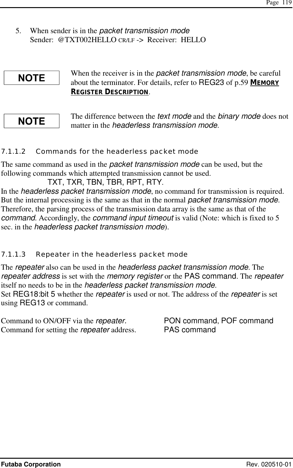
![Page 124 FRH-SD07TU/TB Manual Rev. 020510-01 7.1.4 Memory Register Settings The basic setup is the same as that of normal packet transmission mode (mode 3 and 4). In the headerless packet mode, the following settings should be added. REG02: Destination Address Default value: 00H Set the address of the modem to transmit data as the destination address. Setting to 000 to 239 is available (240 addresses). This value is padded to the transmission data packet to transmit to the destination address. When address checking function (REG18) is valid, set the address of the receiving modem to this register. DAS command can change this destination address. REG03: Operation Mode Setting Default value: F0H Set the operation mode to the headerless packet transmission mode (FFH). REG13: Repeater Address Default value: 1EH When a repeater is used, set the repeater address to pass through. REG16: Terminator Setup 1 Default value: 32H Set an arbitrary 1 byte terminator. In case of a 2-byte terminator, set the first byte character of the terminator. The command input timeout is fixed to 5 sec. REG17: Terminator Setup 2 Default value: 32H Set another arbitrary 1 byte terminator. In case of a 2-byte terminator, set the last character of the terminator. REG18: Communication Setting 1 [default value: 8CH] Bits 7 – 6: Reserved • The FRH-SD07TU/TB does not use this register. Keep the default value as it is.](https://usermanual.wiki/Futaba/FRH-SD07TU.Users-Manual/User-Guide-251104-Page-140.png)
![Page 125 Futaba Corporation Rev. 020510-01 Bit 5: Transmission path select 0 transmit directly to destination (default value) 1 transmit indirectly via repeater Table 7–3: Transmission path selection • To transmit a packet data through the repeater, set the repeater address to REG13. Bit 4 Transmission format 0 transmit in the test form (default value) 1 transmit in the binary form Table 7–4 Transmission format • Selects the transmission format. When data are transmitted to the destination station which is set to the normal packet transmission mode, output text format (RXT, RBN) from the receiver modem (destination station) differs depend on this setting. • This setting does not effect in the receiver modem set as headerless packet transmission mode. Bits 3 – 2 Terminator Setting bit 3 bit 2 setting 0 0 two kinds of arbitrary 1 byte code (REG16, REG17) 0 1 arbitrary 1 byte code (REG16) + a wild card (any character) 1 0 arbitrary 2 byte code (REG16 + REG17) 1 1 carriage return (CR) + line feed (LF) (default value) Table 7–5 Terminator setting • Sets the terminator to identify the breakpoint of a packet. The modem transmits data considering this character as the breakpoint of a packet. • In case of using an arbitrary terminator, set it to REG16 and 17. Bit 1: Source address check • The same function as the basic function. Bit 0: Destination address check • The same function as the basic function. REG23: Interface Setting 4 [default value: 00H] The same function as the basic function, except bit 4.](https://usermanual.wiki/Futaba/FRH-SD07TU.Users-Manual/User-Guide-251104-Page-141.png)
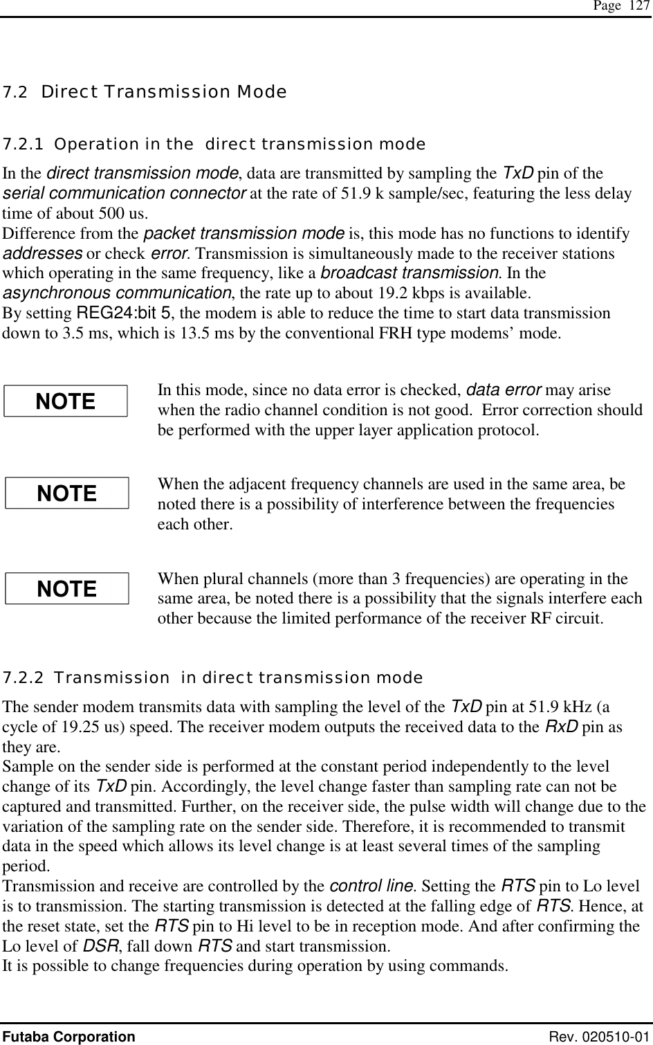
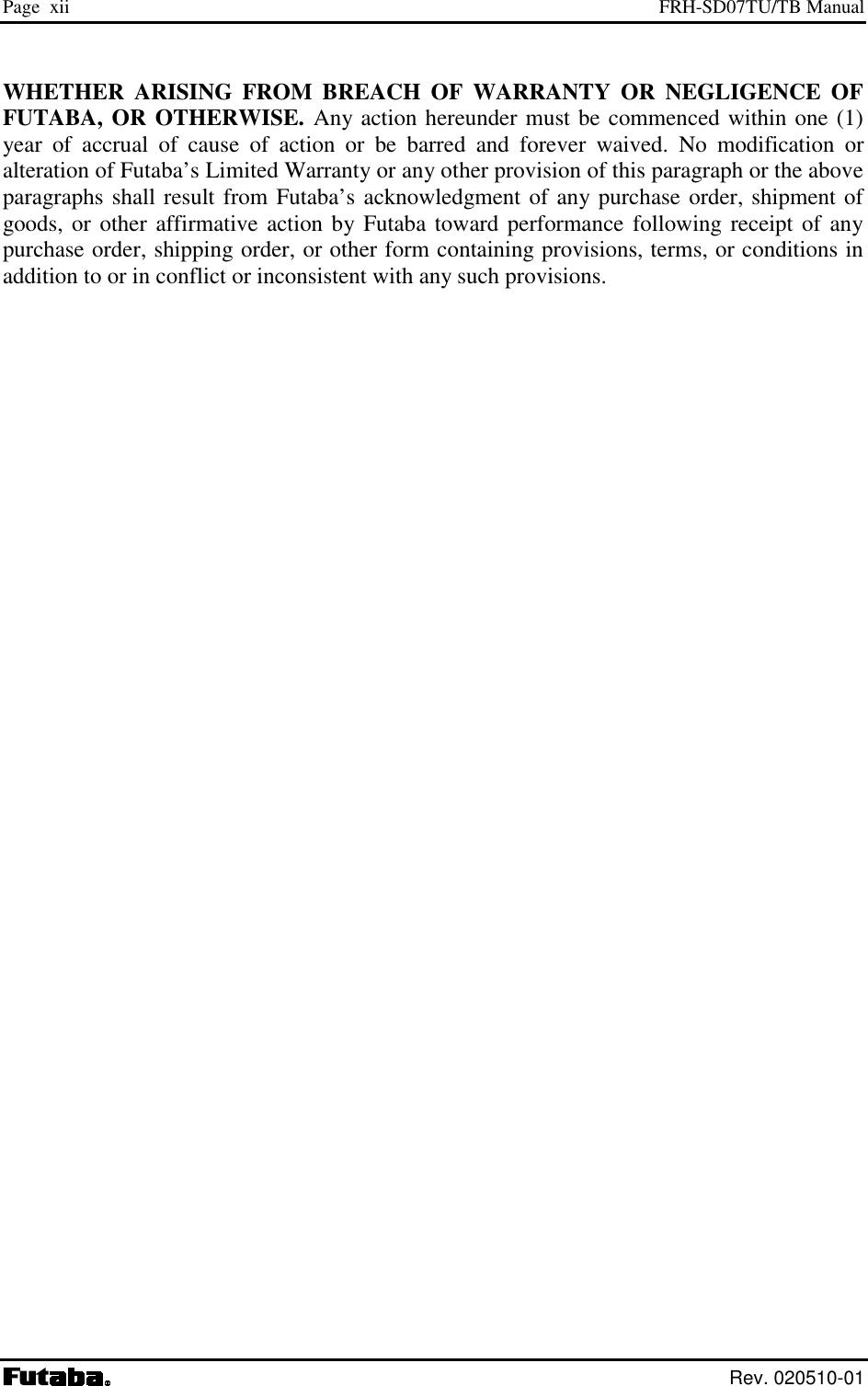
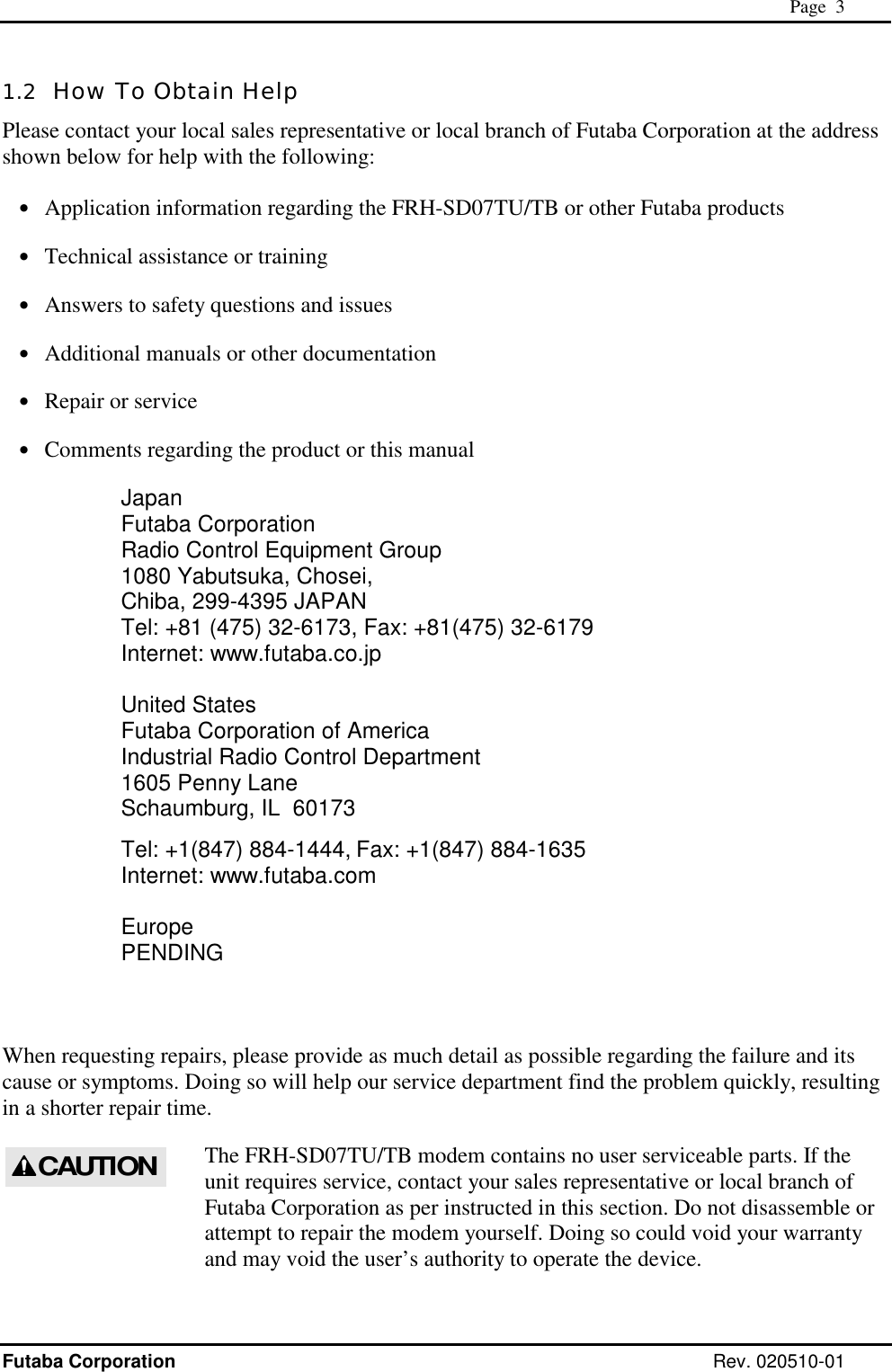
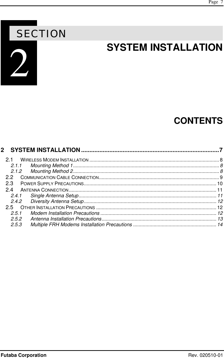
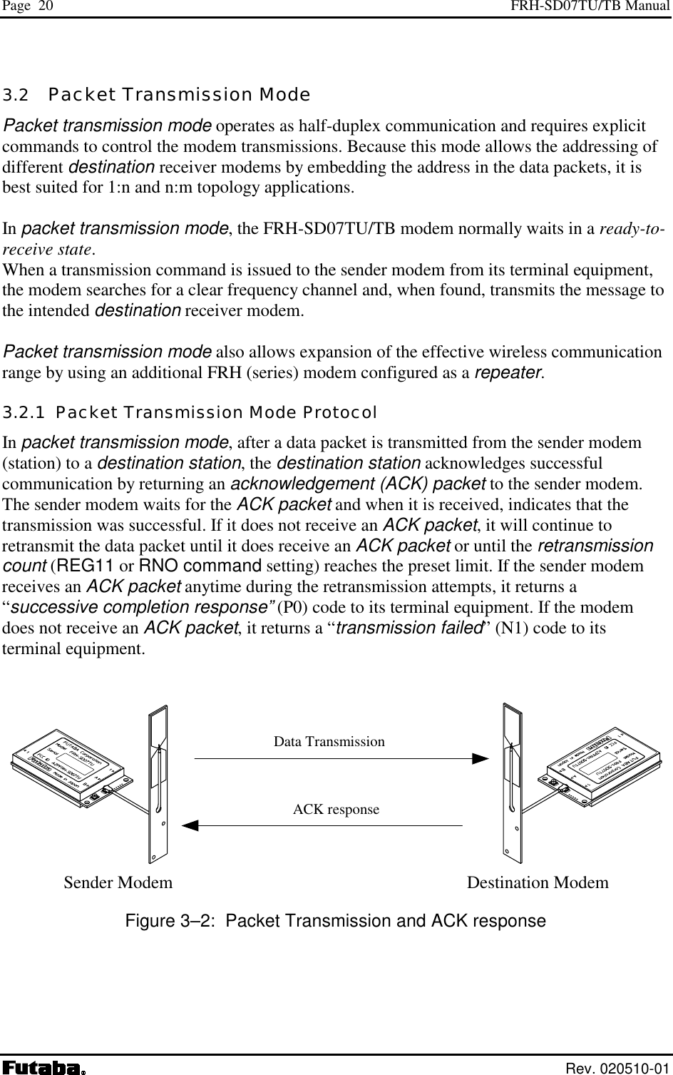
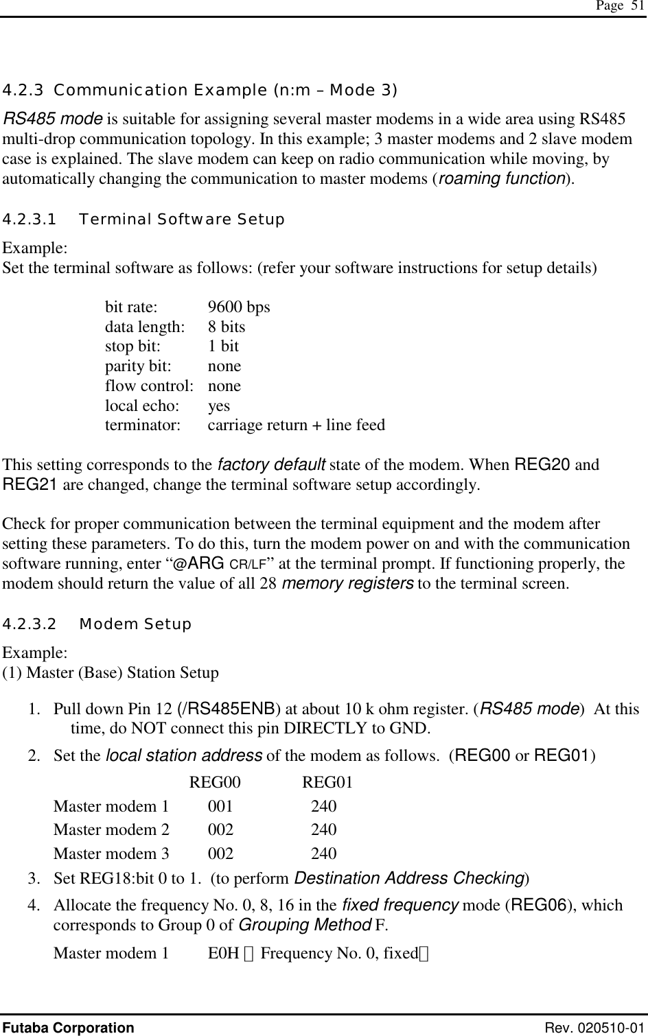
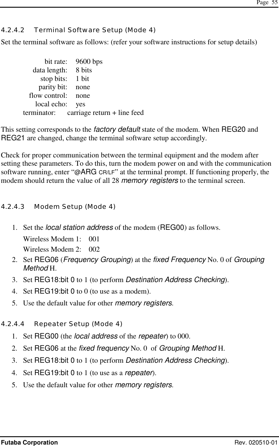
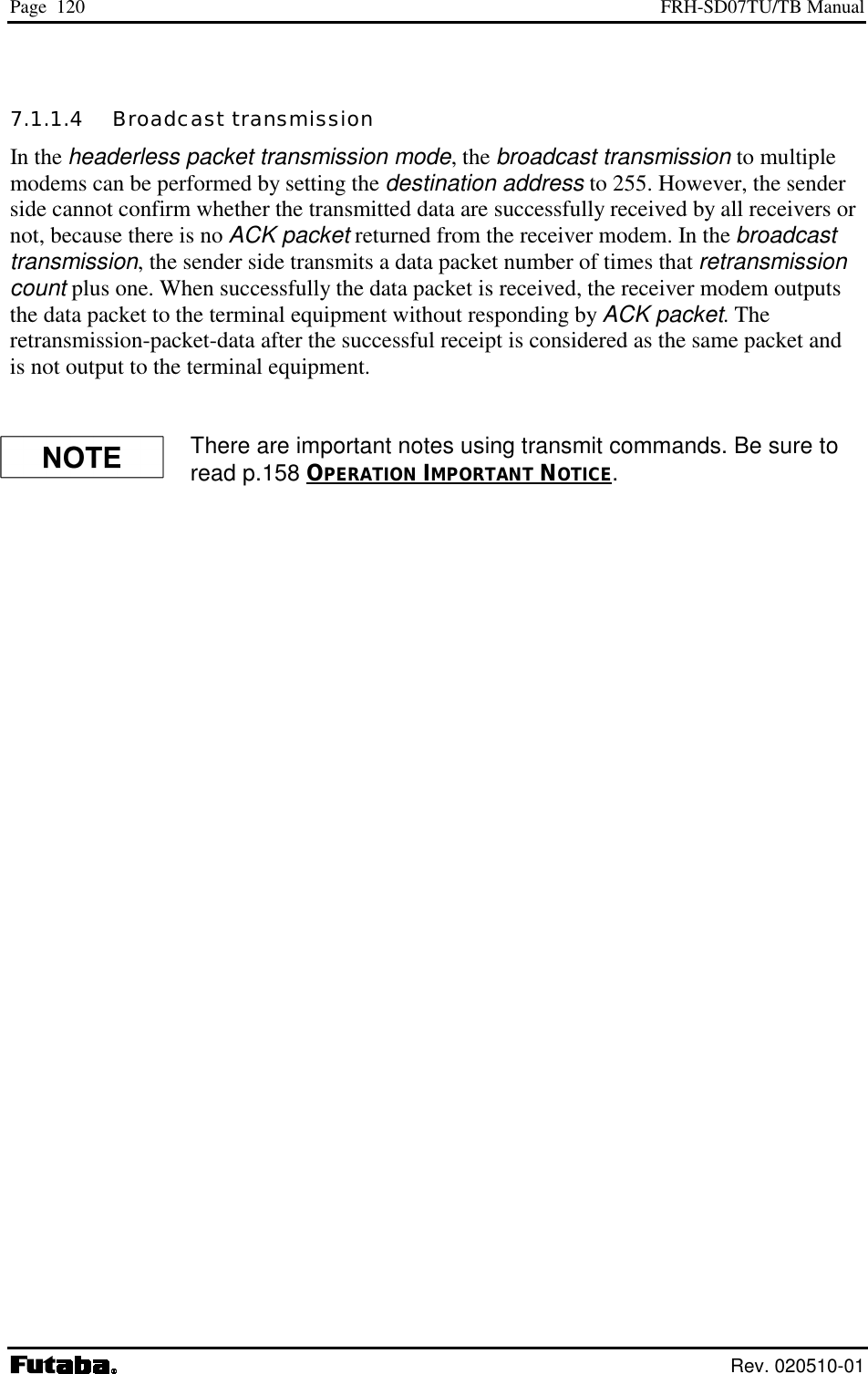
![Page 128 FRH-SD07TU/TB Manual Rev. 020510-01 The direct transmission mode features less delay time between the input of the transmit data and the output of the receive data, i.e. about 500 us. Figure 7–1: Transmission on Direct Transmission Mode If the other end modem is the conventional type, such as FRH-SD03TU, logic level is reverse that of FRH-SD07TU/TB. When FRH-SD07TU/TB transmits [1], the conventional type modem receives [0]. Transmitting Side TxD Input Sampling Transmission Data Receiving Side Receive Data RxD Output](https://usermanual.wiki/Futaba/FRH-SD07TU.Users-Manual/User-Guide-251104-Page-144.png)
![Page 129 Futaba Corporation Rev. 020510-01 7.2.3 Memory Register Settings In the direct transmission mode, set the following parameters. Keep other parameters as being the factory default values. REG03: Operation Mode Setting Default value: F0H Set the operation mode to the direct transmission mode (01H). REG06: Frequency Setting Default value: A0H Set the frequency in operation. It is the same function as the basic function. Fixed frequency mode is preferred to use in the direct transmission mode. REG19: Communication Setting 2 [default value: 00H] Only bit 6 is used. Use other bits than bit 6 as they are default values. Bit 6: Diversity reception • The same function as the basic function is valid. REG20: RS-232C Setting 1 [default value: 05H] ・ Set the communication parameter to be used to accept command. The same function as the basic function is valid. ・ Since TxD is sampled at 51.9 kHz, there is no relation between this setting and the actual communication speed. REG24: Special Mode Settings [default value: C0H] Bit 7 – 6: reserved • The direct transmission mode does not use this register. Keep the default value as it is. Bit 5: Delay time of transmission and reception (direct communication mode) 0 same delay time of the conventional type (13.5 ms, default value) 1 shorter delay time (3.5 ms) Table 7–8: Setting of delay time of transmission and reception in the direct communication mode](https://usermanual.wiki/Futaba/FRH-SD07TU.Users-Manual/User-Guide-251104-Page-145.png)
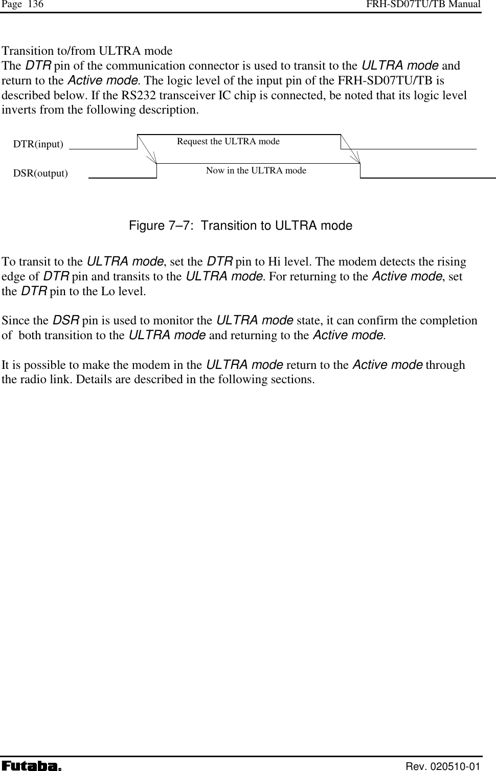
![Page 139 Futaba Corporation Rev. 020510-01 7.3.3 Wakeup command For these commands, refer to Chapter 6. 7.3.3.1 Direct wakeup : RLU command Transmit Command Use the RLU command to wakeup the modem in the ULTRA mode. Command format: @RLU [Destination address]CR/LF [Destination address]designates the destination (which is in the ULTRA mode) address (the set value of REG00 of the receiving station in the ULTRA mode). Broadcasting wakeup request packet (address 255) is also available. When the command is accepted, “P1” response is output and the wakeup request packet is transmitted. Wakeup ACK and response The modem in the ULTRA mode, which received the wakeup request packet, always checks destination address regardless of the status of REG19:bit 0. Accordingly, the modem does not wakeup unless addresses correspond to each other. When the modem receives wakeup request packet and being Active mode, its modem returns ACK packet which inform the modem has been returning to Active mode, unless the Broadcasting wakeup (destination address: 255) is designated. The sender modem receives ACK from the destination station, it outputs “P0” response following the “P1” response. In case of being unable to wakeup, ACK not received, or wrong destination address, “N1” response will output which follows “P1” response. When REG25:bit 7 is set to be the ULTRA mode enable, the modem returns ACK to the wakeup request packet even the modem is in the wakeup state (Active mode). Therefore, “P1” response will output after the “P0” response when the RLU command is issued for the destination station in the Active mode. Broadcast wakeup When 255 is designated to [destination address] field, all receiver station does not return ACK packet even these are being waken-up. So, as the command response, “P0” is output always following “P1” output, after the defined number of retransmission count. In this case, it is not assured whether the stations returns to the Active mode or not. It is recommended to issue TXT command (to attempt communication) and such to the destination station, for to confirm whether ACK packet is obtained or not from the destination station.](https://usermanual.wiki/Futaba/FRH-SD07TU.Users-Manual/User-Guide-251104-Page-155.png)
![Page 140 FRH-SD07TU/TB Manual Rev. 020510-01 Figure 7–9: Wakeup using RLU command 7.3.3.2 Wakeup through repeater : RLR command Transmit command Use the RLR command to wakeup the modem in the ULTRA mode, through the repeater. Command format : @RLR[repeater address] [destination address]CR/LF [repeater address] designates the repeater to transmit the wakeup request. [destination address] designate the station address (the set value of REG00) to be waken-up. Broadcasting wakeup (address 255) is also available. On accepting this command, the modem returns “P1” response and starts transmitting wakeup transmission request packet to the repeater. And this packet makes the repeater to transmit the wakeup request packet to the destination(s). The transmission of wakeup request packet The sender station transmits the wakeup transmission request to the repeater, its request making the repeater to transmit the wakeup request packet to the destination(s). The wakeup transmission request is repeated to transmit at the cycle of 200 ms by the retransmission count designated by REG11 or RNO command. At the repeater, the destination address checking function set by REG18:bit 0 is valid. Accordingly, when the function is set to be valid, the repeater does not receive the wakeup transmission request unless the repeater address matches. When the repeater receives the wakeup transmission request, it transmits the wakeup request packet to the destination station designated by [destination address] for 160 ms duration. Though ACK packet is returned from the destination station, the repeater ignores it and does not return ACK packet to the sender station. Therefore, even when the single station is designated by the [destination address], the sender station cannot confirm whether the destination station wakes-up or not. It is necessary to issue TXR command (to attempt communication) and such to the destination station, for to confirm whether response is obtained or not from the destination station. Wake-up Req. packet ACK](https://usermanual.wiki/Futaba/FRH-SD07TU.Users-Manual/User-Guide-251104-Page-156.png)
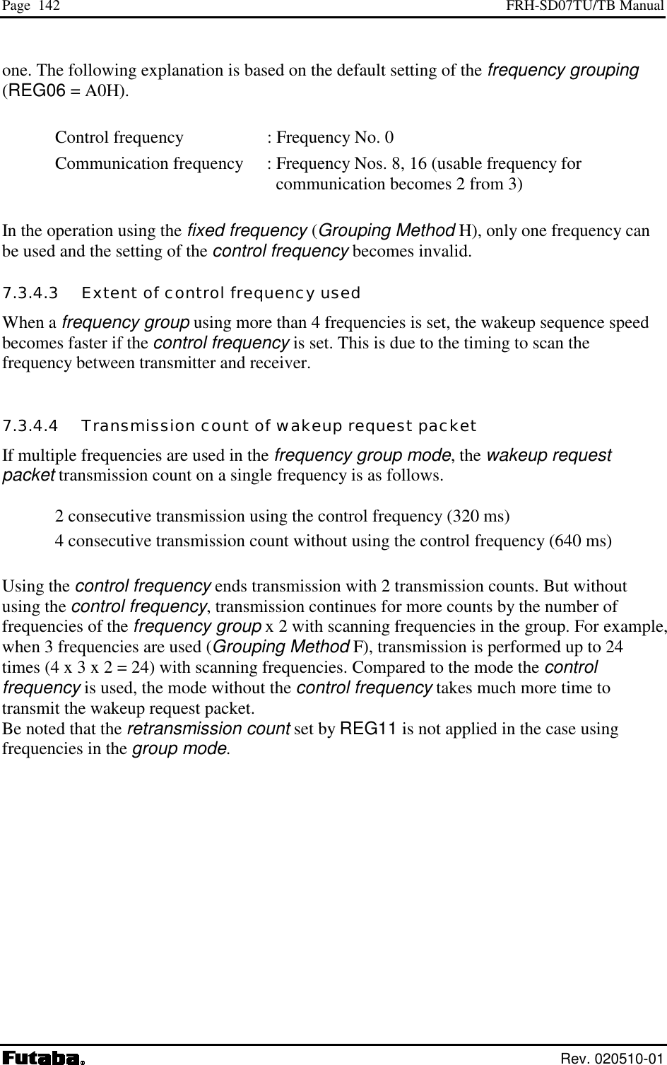
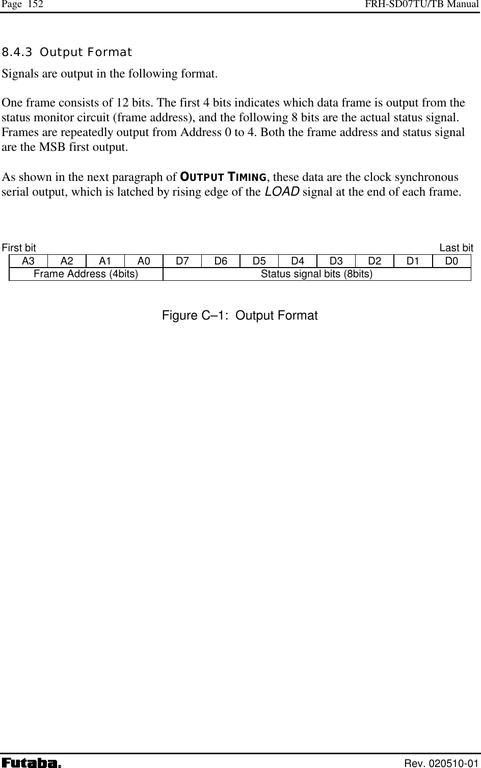
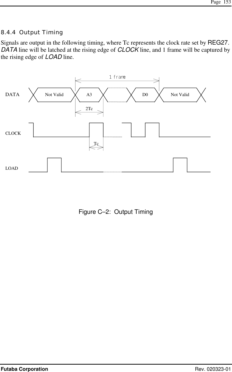
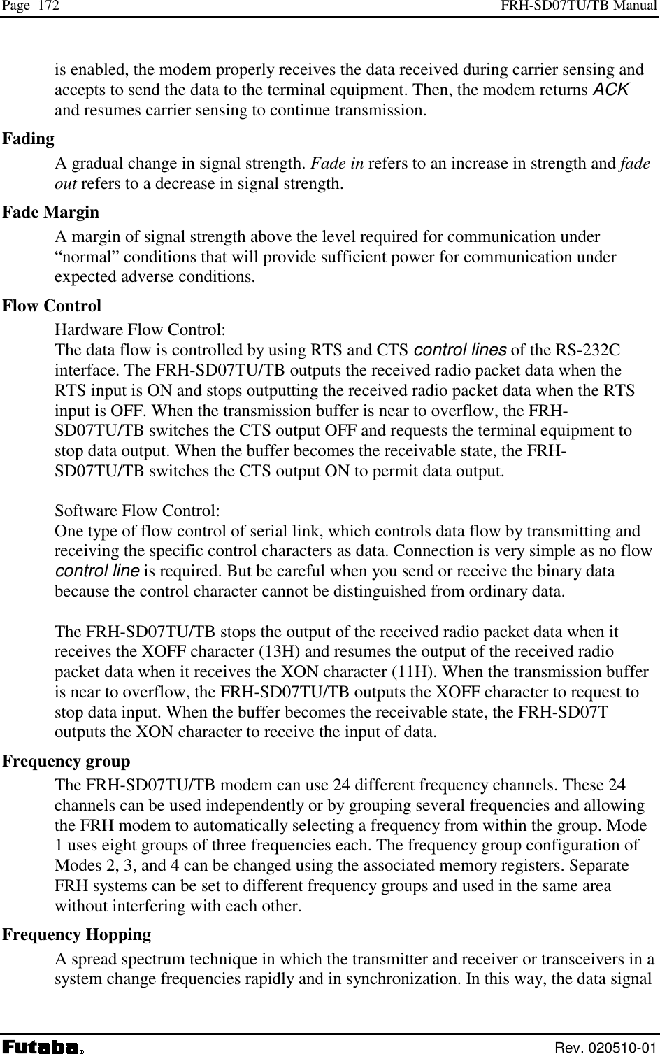
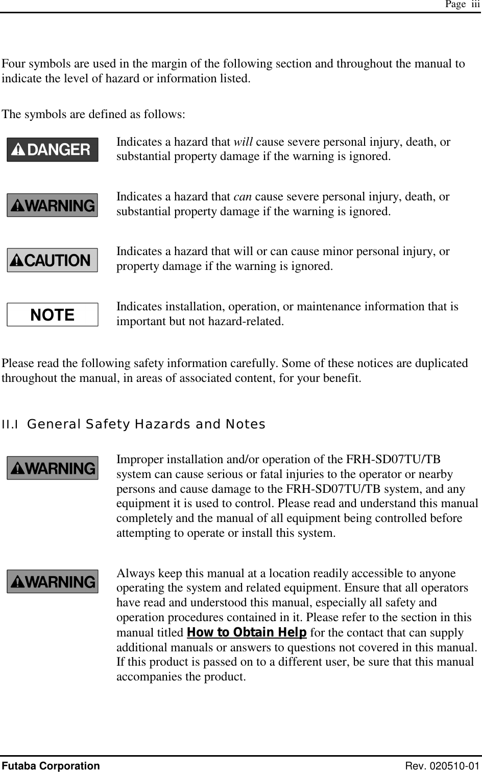
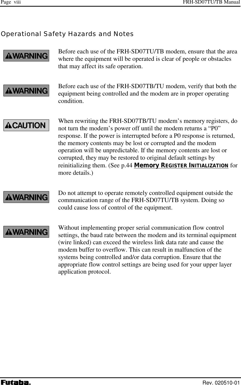
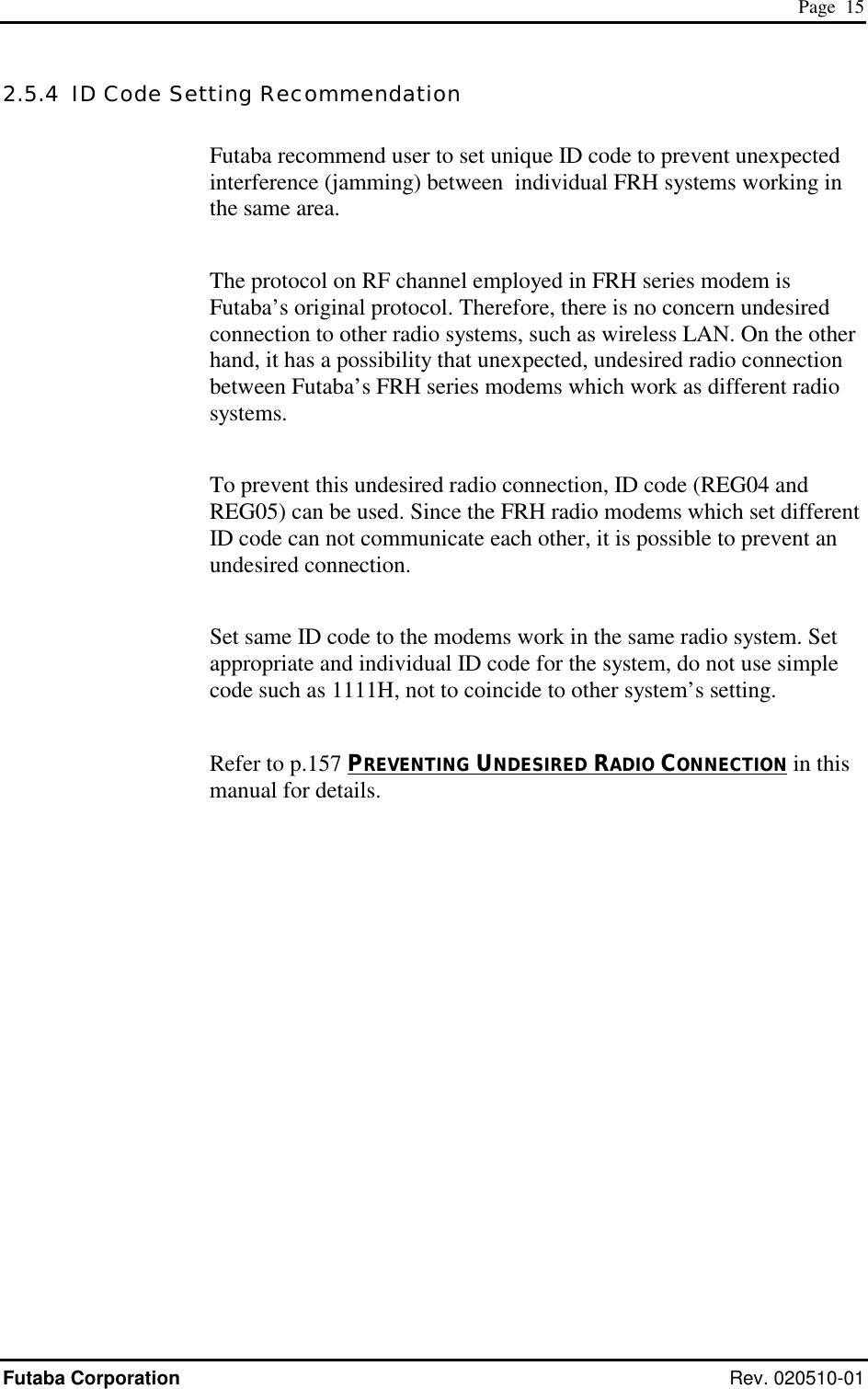
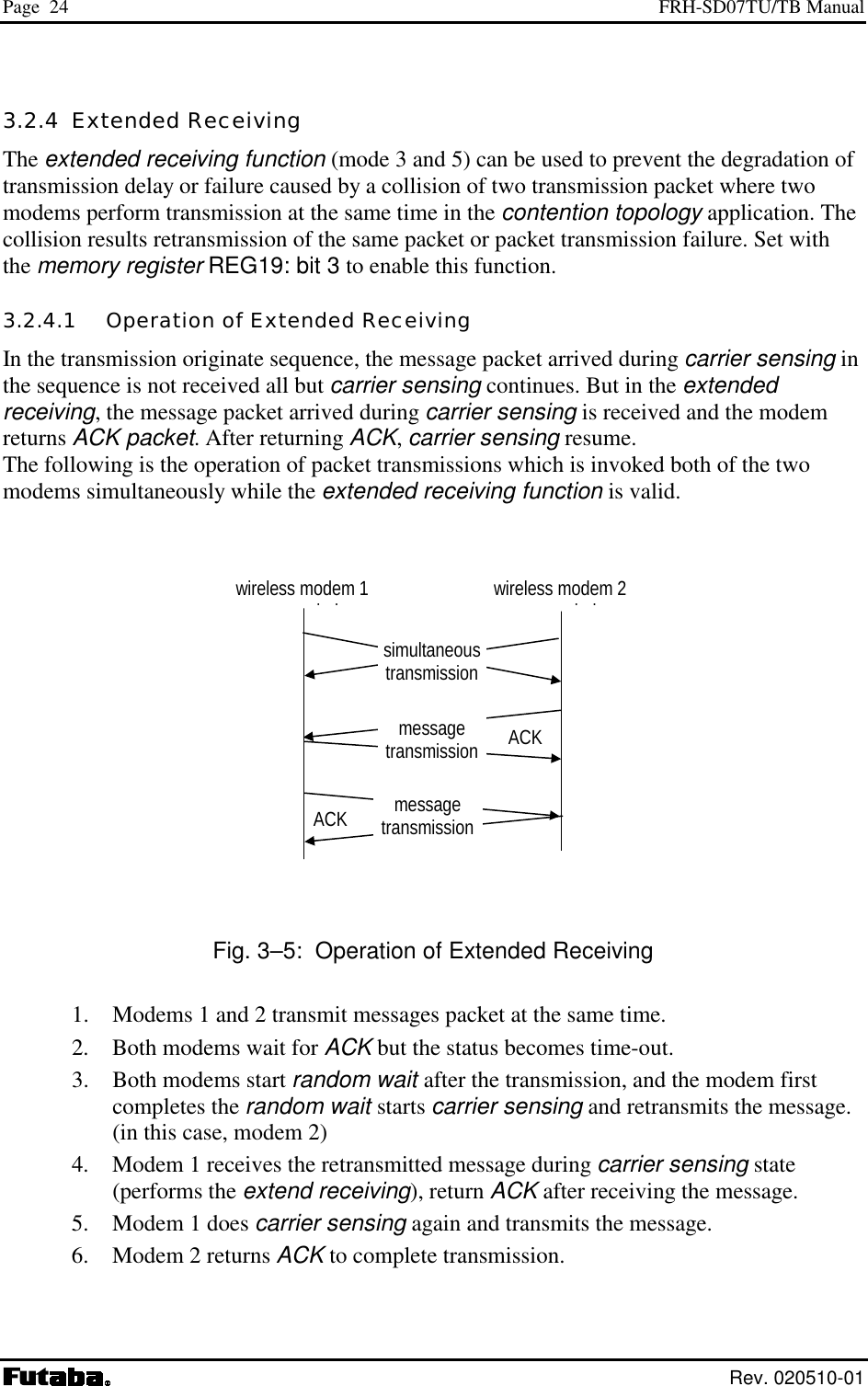
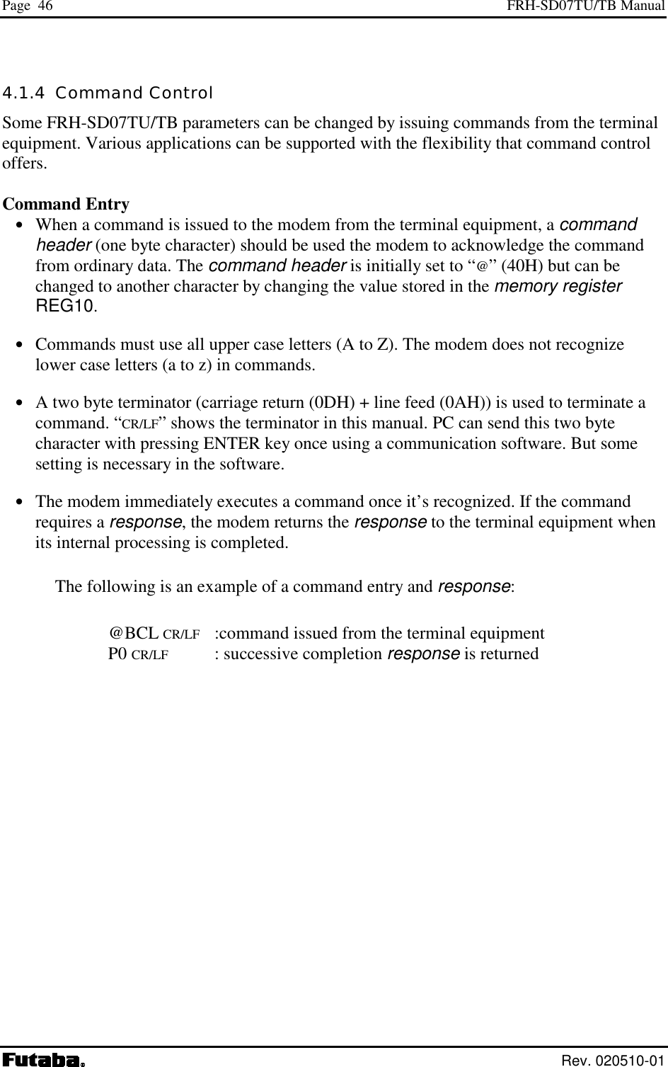
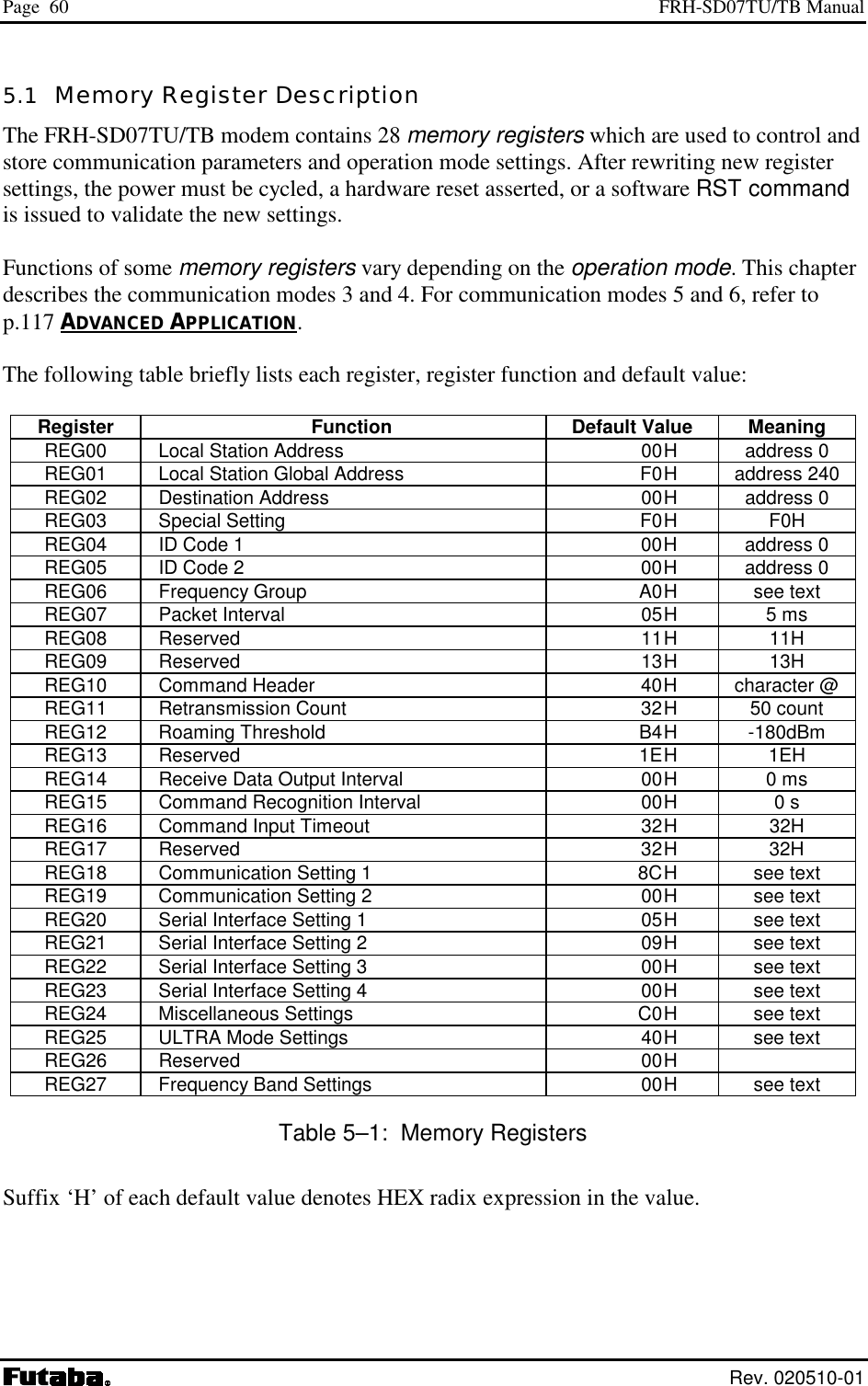
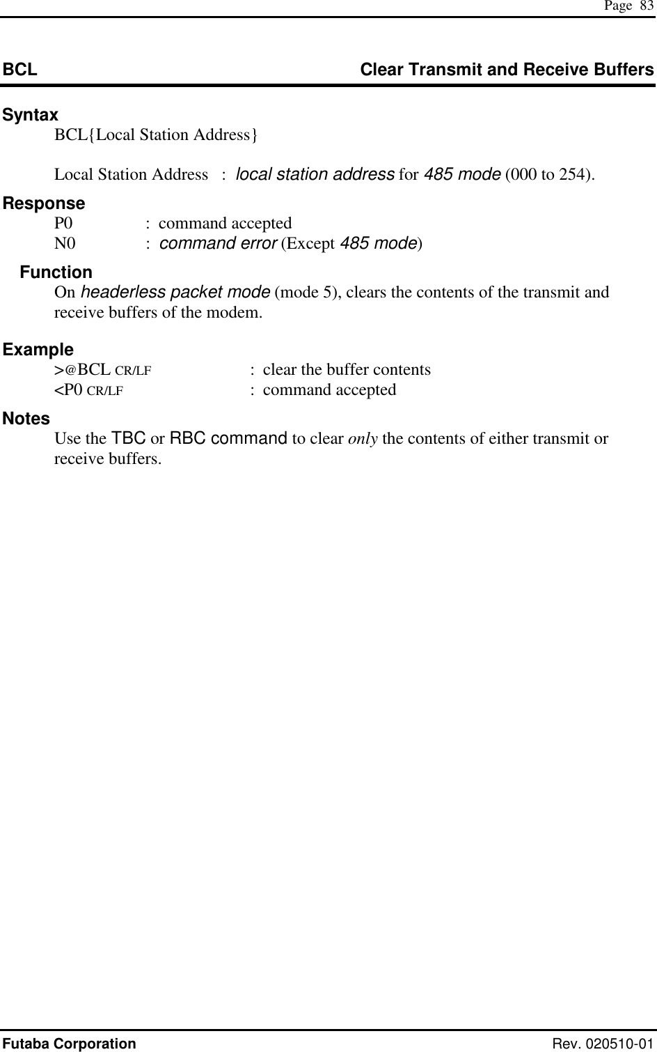
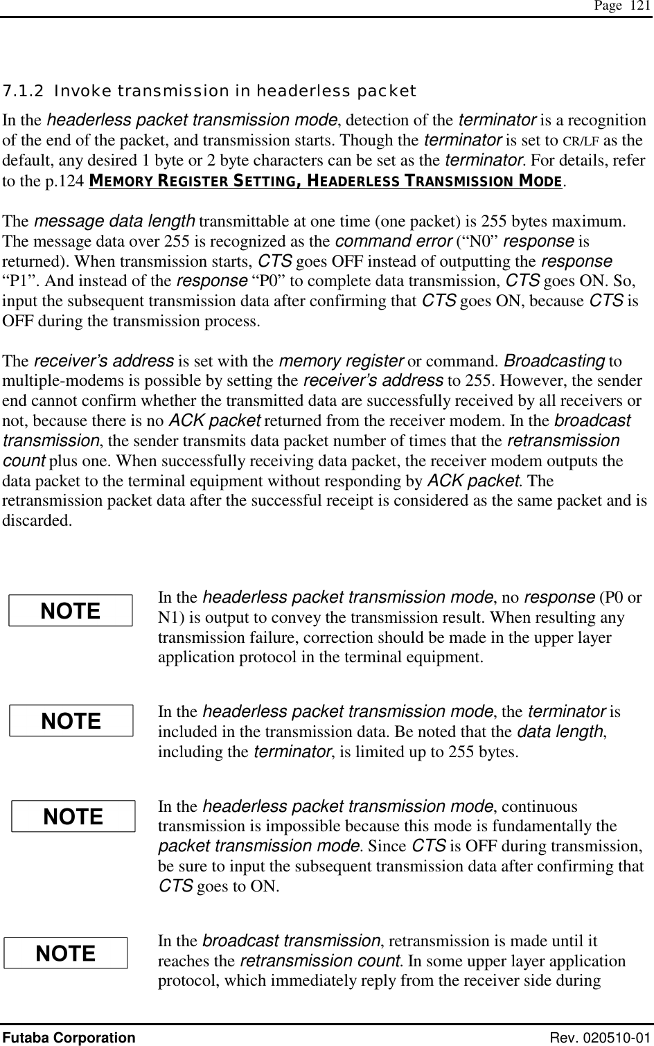
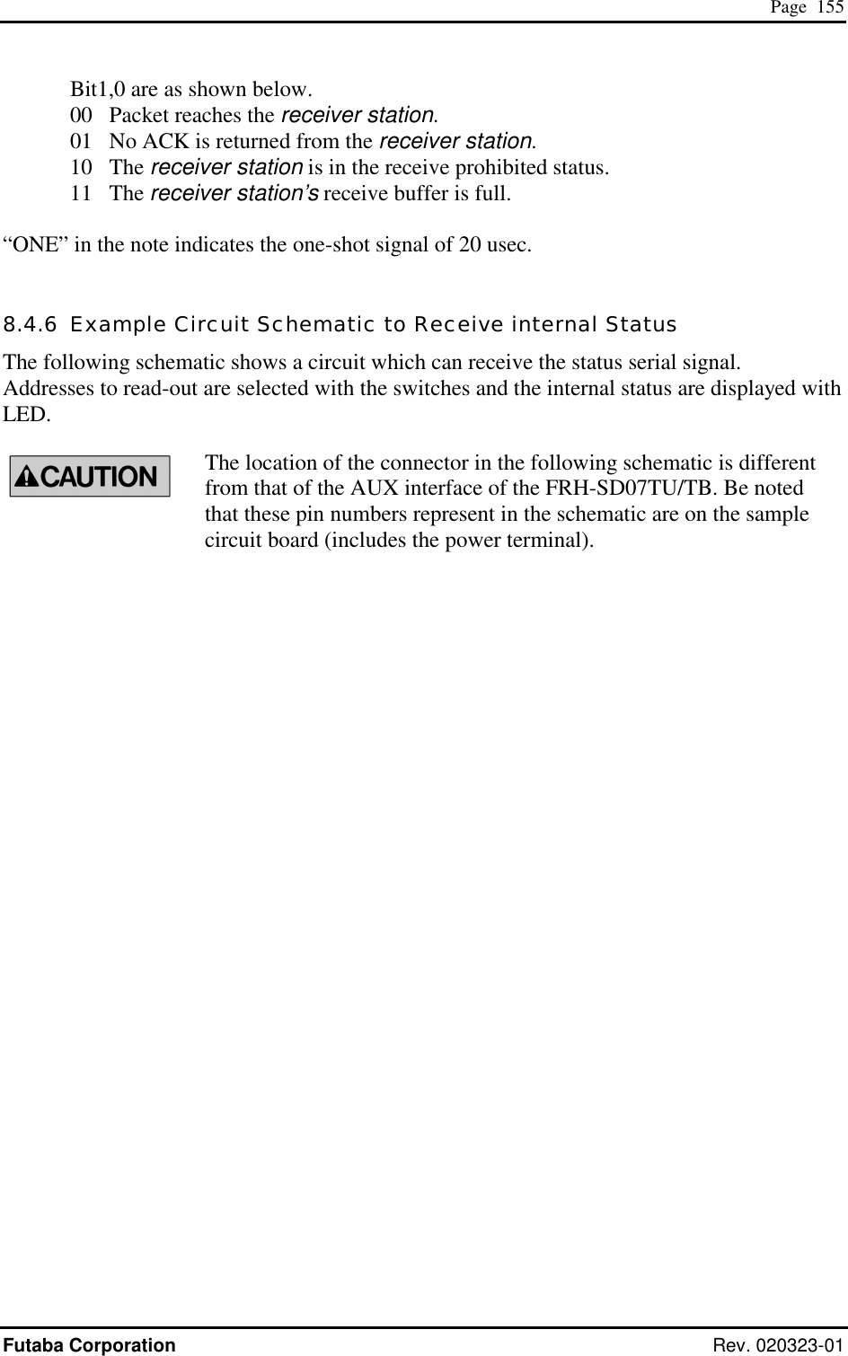
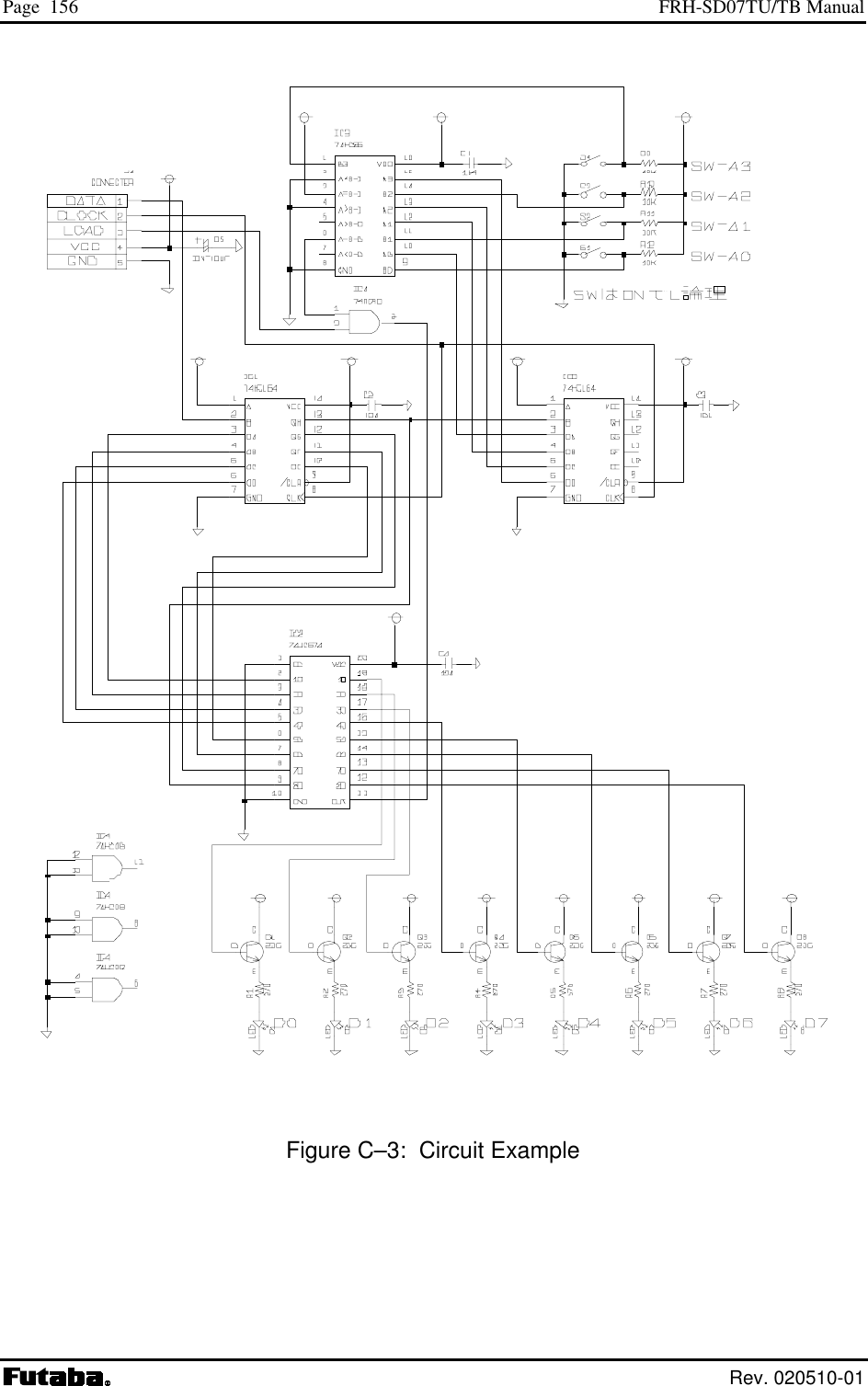
![Page 154 FRH-SD07TU/TB Manual Rev. 020510-01 8.4.5 Output Status Data The status data having the following contents are output. Frame address Status signal bit number Signal name Contents Note D7 CorrelationDetect Hi while correlation is detecting D6 FrameSyncDetect Hi when frame-sync is detected, Lo when correlation is lost D5 TransparentLinkEstablished Not used D4 OperateInUltraMode Hi while operating in ULTRA mode D3 FreqChangeExecuting Hi while frequency is changing D2 OperatingTransmissionCommand Hi while transmission command is executing D1 TrxCtrlSeqIsPacketIdle Hi while no TX/RX operation is executing 0 D0 SystemErrorState Hi when system error occurred D7 ReceiveSuccess Hi when receive success ONE D6 ReceiveMyAckSuccess Hi when ACK receive success ONE D5 Receive1packetError Hi when received but error occurred ONE D4 DetectJabberPacket Hi while wakeup packet is receiving D3 TransmissionSequenceResultCode(2) D2 TransmissionSequenceResultCode(1) D1 TransmissionSequenceResultCode(0) Refer to note[1] 1 D0 0 D7 RxBufferFull Hi while the receive buffer is full D6 RxBufferDataExist Hi while a data is existing in the receive buffer D5 TxBufferFull Hi while the transmission buffer is full (mode 7) D4 TxBufferDataExist Hi while operating in mode 7 D3 TxBufferOverflow Hi while the transmission buffer is overflowing (mode 7) D2 TxDataExistInTransAndFdaHdrless Hi while a data is existing in the transmission buffer 2 D1-0 0 D7 RxDteDataOutputEnable Hi while the serial port is enabled to output D6 RadioDataReceiveEnable Hi while the radio is enabled to receive D5 RsReceivedDataReceptionEnable Hi while the serial port is enabled to receive D4 OperatingFreqChannelRegister(4) D3 OperatingFreqChannelRegister(3) D2 OperatingFreqChannelRegister(2) D1 OperatingFreqChannelRegister(1) 3 D0 OperatingFreqChannelRegister(0) Frequency channel number in operating (0∼23) D7-5 0 D4 TopOperationState(4) D3 TopOperationState(3) D2 TopOperationState(2) D1 TopOperationState(1) 4 D0 TopOperationState(0) Reserved Table C–3: Status Data Note [1] Transmission Sequence Result Code (2-0) Indicates the result of the transmit commands, e.g. TBR and TXT, which last executed. Bit2: ‘H’ when packet reaches to the repeater by the transmit commands passing through the repeater.](https://usermanual.wiki/Futaba/FRH-SD07TU.Users-Manual/User-Guide-251104-Page-170.png)
![Page 157 Futaba Corporation Rev. 020323-01 8.5 Preventing Undesired Radio Connection Futaba recommend user to set unique ID code to prevent unexpected interference (jamming) between individual FRH systems working in the same area. 8.5.1 What is Interfere Problem The “Interference” described here is 8.5.2 What is ID Code ID code is 16 bit word set by REG04 and REG05. The FRH series radio transmits data with code-scramble. Scramble data is made by the seed using this ID code. On the receiver side, de-scramble is performed to restore original data using the same ID code (set on the receiver side memory register) as the seed. Therefore, communication can not be established if both sender and receiver modems do not set an identical ID code. By setting this ID code, the interference problem can be decreased. But because of the FRH modem employs carrier sense function, the function that the modem can not start transmission during carrier is sensing (where other FRH modem station is in transmission) is not affected by this ID code setting. Please do not misunderstand the purpose of this ID code interference measure. 8.5.3 ID Code Setting ID code can be defined by users. FRH-SD07TU/TB modem can set from 0000H to EFFFH 16 bit code, set by upper 8 bit to REG05 and lower 8 bit to REG04. This 16 bit value should be choose as random as possible, to make good performance for this interference problem. However, still there has a possibility that the other system using same ID exists nearby, this countermeasure can not to be perfect such a situation. Please understand this measure is for to decrease the interference problem. It is important to set “random” value for ID code. But if to obtain the value is difficult to image, use below equations to define the ID code for you. Use the product serial number which randomly selected from your FRH-SD07TU/TB modems you own. Product serial number is 9 digits; divide these as [AA][BB][C][DDD][E]. REG05 = [{(AA MOD 10 ) + 11 } x BB] – 1 REG04 = DDD MOD 256 MOD is the modulo operator. [Example] If product serial number is 020809468, AA=2, BB=8, DDD=946. Therefore, REG05 = [{(2 MOD 10) + 11} x 8] –1 = 103 -> 67H REG06 = 946 MODE 256 = 178 -> B2H](https://usermanual.wiki/Futaba/FRH-SD07TU.Users-Manual/User-Guide-251104-Page-173.png)
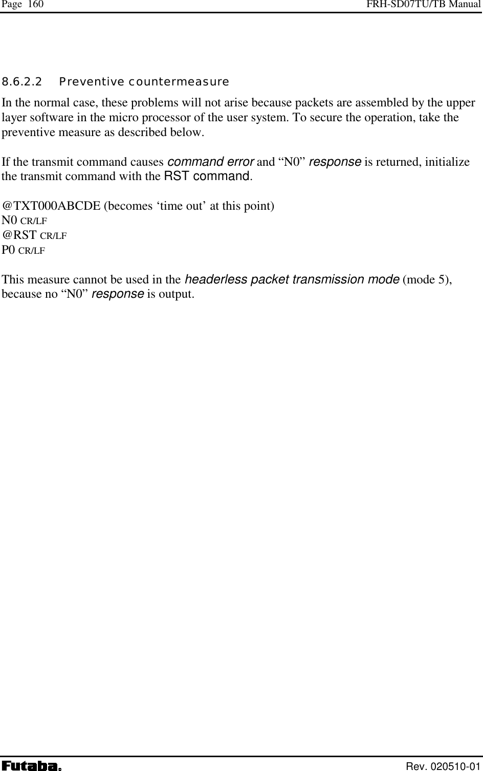
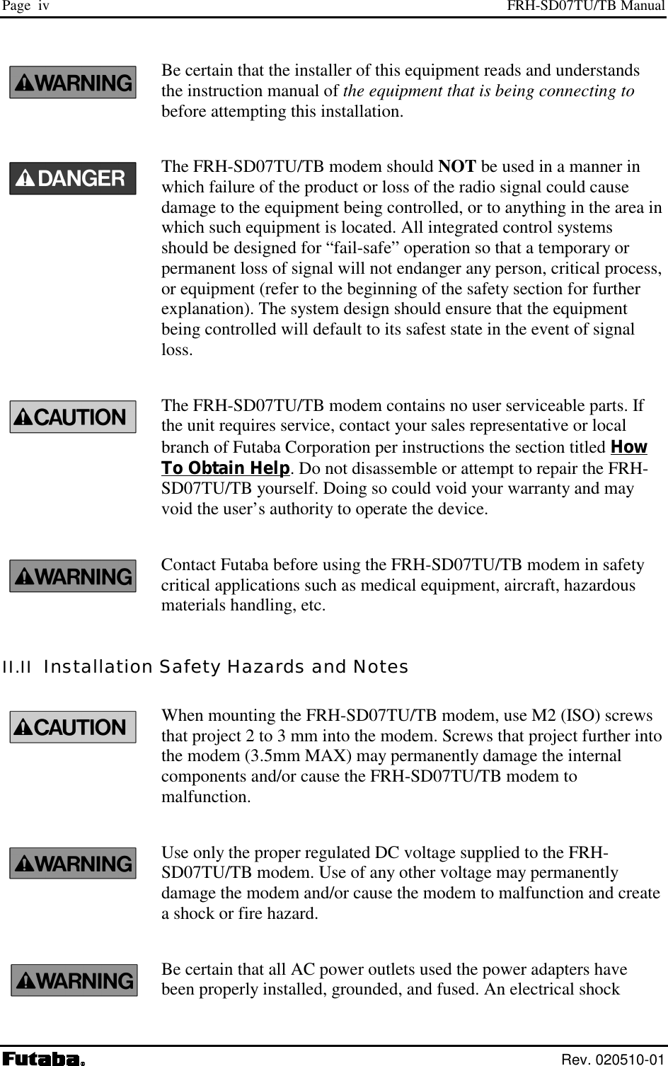
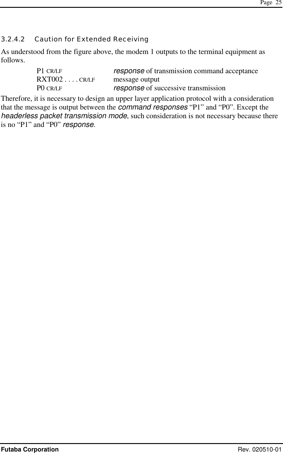
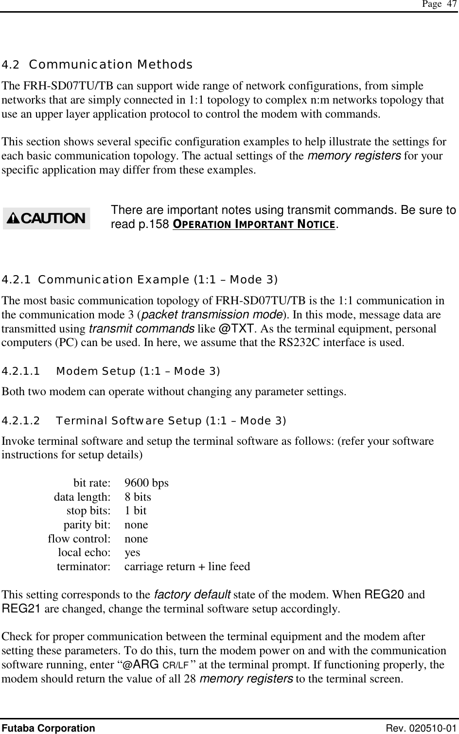
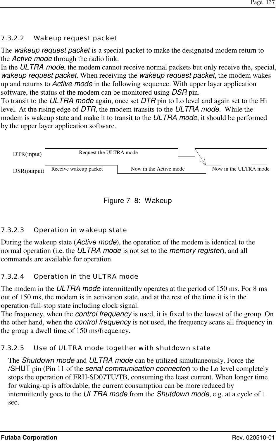
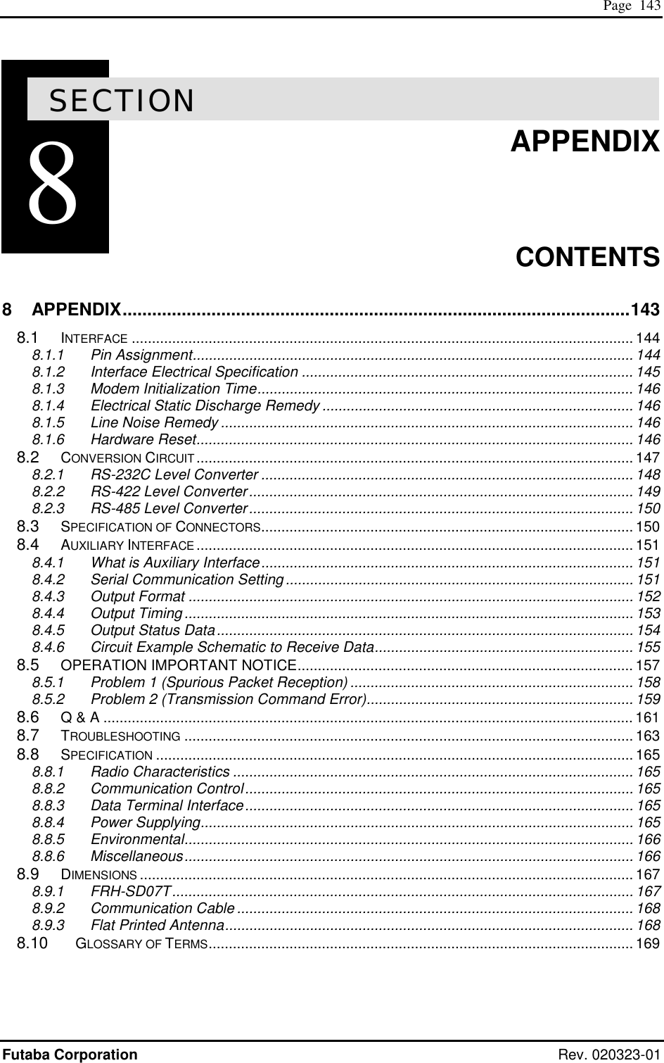
![Page 158 FRH-SD07TU/TB Manual Rev. 020510-01 8.6 OPERATION IMPORTANT NOTICE Problems were found in the current version of FRH-SD07TU/TB (Version 1.00). Before using this product, refer to the preventive measures described below. 8.6.1 Problem 1 (Spurious Packet Transmission) 8.6.1.1 Problem Description At the final retransmission, when the sender modem transmits final packets due to transmit error, ACK packet reception is started but its reception was failed, rarely the sender modem which received ACK packet starts the repetitive “spurious packet” transmission. This spurious packet format is same as that of ACK packet. In the receiver (remote) modem, this spurious packet is recognized as the normal packet and starts receiving. And from remote modem, it returns ACK to the sender modem. Again sender modem recognize this ACK packet as a normal packet and returns ACK to the remote modem. This sequence repeats until radio communication becomes error or next transmission command (such as TXT or TBN) is issued. This problem tends to occurs in a retransmission count is set to 0. Local (address 123) Remote (address 210) Last retransmission Receive successfully ACK receive error RXT123 CRLF RXT210 CRLF RXT123 CRLF RXT210 CRLF RXT123 CRLF RXT210 CRLF Continue till receive error When this problem occurs, both sender and remote modem repetitively output vacant packet data (only header information) to the both terminal equipment. [Example] @TXT000AAA CR/LF N1 CR/LF RXT012 CR/LF (Spurious packet) The probability of this problem occurs, it becomes large, when the retransmission count (which set by RNO command or REG11) is set to small. Data packet Spurious packet ACK ACK ACK ACK ACK ACK](https://usermanual.wiki/Futaba/FRH-SD07TU.Users-Manual/User-Guide-251104-Page-174.png)
![Page 159 Futaba Corporation Rev. 020323-01 8.6.1.2 Preventive countermeasure If terminal equipment (or upper layer software) detects the spurious packet (header information only), then discard this packet, and issue RST command or force /SHUT pin (11pin) of the serial communication connector to low. The operation results modem to reset. Once either side modem is being reset, this repetitive spurious packet stops and the modem returns to normal operation mode. 8.6.2 Problem 2 (Transmission Command Error) 8.6.2.1 Its problem description In the mode 3 and 5 (packet transmission mode and headerless packet transmission mode), when the TBN, TBR, TXR and TXT commands (or headerless transmission command) are issued, wrong data are output to the receiver modem’s terminal equipment under the following condition. As shown in the example, when the transmit command becomes error, the command error response is returned. [Example 1] @TXT000AAAAAAAAA.............AAA (excessive bytes due to the input maximum of 256 byte) N0 CR/LF [Example 2] @TXT000ABCDE (becomes ‘time out’ at this point) N0 CR/LF If the next transmit command is issued at this stage and this command is successfully accepted and performed, the wrong data (the contents of the last transmission-command data) are send as the radio packet and output to the receiver end terminal equipment. The contents of the “accepted, the next” transmission command data will not be transmitted. (Refer the following example.) @TXT000ABCDE (becomes ‘time out’ at this point) N0 CR/LF @TXT000KLMN CR/LF P1 CR/LF P0 CR/LF @RXT000ABCD CR/LF (KLMN will be output.)](https://usermanual.wiki/Futaba/FRH-SD07TU.Users-Manual/User-Guide-251104-Page-175.png)