Futaba FRH-SD07TU RF Modem using digital modulation User Manual
Futaba Corporation RF Modem using digital modulation Users Manual
Futaba >
Contents
- 1. Users Manual
- 2. User Manual
Users Manual

WIRELESS DATA COMMUNICATION MODEM
FRH-SD07TU (US Version)
FRH-SD07TB (EU Version)
Ultra Low Power Consumption
Wireless Modem with Serial Interface
Instruction Manual
Futaba Corporation
Industrial Radio Control

Page i
Futaba Corporation Rev. 020510-01
I Notice
This device complies with part 15 of the FCC rules and with ETS 300 440 of the European
Telecommunication Standard Institute (ETSI). Operation is subject to the following two
conditions: (1) This device may not cause harmful interference, and (2) this device must
accept any interference received, including interference that may cause undesired operation.
This equipment has been tested and found to comply with the limits for a Class A digital
device, pursuant to part 15 of the FCC Rules. These limits are designed to provide reasonable
protection against harmful interference when the equipment is operated in a commercial
environment. This equipment generates, uses, and can radiate radio frequency energy and, if
not installed and used in accordance with the instruction manual, may cause harmful
interference to radio communications. Operation of this equipment in a residential area is
likely to cause harmful interference in which case the user will be required to correct the
interference at his own expense.
Any unauthorized changes or modifications to this device not expressly approved by Futaba
Corporation could void the user’s authority to operate the device and possibly result in
damage to the equipment and/or cause serious or fatal injuries to the operator or nearby
personnel.
This device is intended to be installed and used in accordance with the instructions contained
in this manual. Failure to comply with these instructions could void the user’s authority to
operate the device and possibly result in damage to the equipment and/or cause serious or
fatal injuries to the operator or nearby personnel.
[Especially for users in Europe]
FRH-SD07TB, European version can be used in the following countries: Austria, Belgium,
Denmark, Estonia, Finland, France, Germany, Greece, Iceland, Ireland, Italy, Luxembourg,
Norway, Portugal, Spain, Sweden, Switzerland, The Netherlands and United Kingdom (the
Czech Republic and Hungary with limitation, see below).
In France and Spain, usable frequency is limited by its country’s regulatory authority. See
p.35 FREQUENCY GROUPING for the frequency usage limitation.
Belgium does not authorize FRH-SD07TB itself. FRH-SD07TB must be fitted into the final
product, then tested to Radio, EMC and safety requirements. A notification will be only
accepted for the final product then.
Users in the Czech Republic and Hungary can use FRH-SD07TB modem, but it has some
limitation for operation. Please contact local regulatory authority to obtain details before
attempt to use FRH-SD07TB modem in that countries.

Page ii FRH-SD07TU/TB Manual
Rev. 020510-01
II Important Safety Information
The list of dangers, warnings and cautions in this section contain important information that
will help ensure safe operation of the system. Please read carefully and understand all of
these items. All installers, operators and maintenance personnel should read and understand
this information before installation, use, or maintenance of the FRH-SD07TU/TB system.
The FRH-SD07TU/TB system by itself is not inherently dangerous. HOWEVER, WHEN
THE FRH-SD07TU/TB IS CONNECTED TO OTHER EQUIPMENT FOR THE
PURPOSE OF CONTROL, SAFETY AND ALL POSSIBLE ASSOCIATED
DANGERS MUST ALWAYS BE GIVEN THE UTMOST CONSIDERATION
DURING SYSTEM INTEGRATION, DESIGN, INSTALLATION, AND USE.
The FRH-SD07TU/TB system may be used in virtually unlimited applications. Many of
these associated systems can, by themselves, pose a mechanical, electrical or other hazard to
operators and other persons or equipment. To address all possible applications and associated
safety hazards in this manual would be impossible. The warnings below and throughout this
manual give information that will allow safe installation and use the modem system
applications. If you have questions regarding the safety of your specific application, please
contact the appropriate people for help. Your Futaba sales representative, representatives of
the equipment being controlled, and the technical support staff at local branch of Futaba
Corporation are among those who can provide assistance with your safety concerns.
The following warnings are included in the lists that follow but warrant repetition here:
In installations where the FRH-SD07TU/TB system is used to control motion or operation of
potentially dangerous equipment, it is imperative for safety that all operators and installers be
thoroughly trained in the normal function of that equipment before attempting to control it
remotely with the FRH-SD07TU/TB system.
To help ensure safe operation of the equipment, the FRH-SD07TU/TB system must be
connected so that it will operate in a fail-safe way. In other words, the equipment being
controlled should stop or return to its safest state in the absence of a control signal or total
loss of RF transmission from the FRH-SD07TU/TB system. Our system uses one of the most
reliable methods available to transmit data using radio signals. Many factors can affect a
radio signal that may block it or interfere enough to disrupt regular transmission. Because of
this, equipment motion or dangerous electrical current, for example, that continues during a
loss-of-signal condition could be very dangerous.
Page iii
Futaba Corporation Rev. 020510-01
Four symbols are used in the margin of the following section and throughout the manual to
indicate the level of hazard or information listed.
The symbols are defined as follows:
Indicates a hazard that will cause severe personal injury, death, or
substantial property damage if the warning is ignored.
Indicates a hazard that can cause severe personal injury, death, or
substantial property damage if the warning is ignored.
Indicates a hazard that will or can cause minor personal injury, or
property damage if the warning is ignored.
Indicates installation, operation, or maintenance information that is
important but not hazard-related.
Please read the following safety information carefully. Some of these notices are duplicated
throughout the manual, in areas of associated content, for your benefit.
II.I General Safety Hazards and Notes
Improper installation and/or operation of the FRH-SD07TU/TB
system can cause serious or fatal injuries to the operator or nearby
persons and cause damage to the FRH-SD07TU/TB system, and any
equipment it is used to control. Please read and understand this manual
completely and the manual of all equipment being controlled before
attempting to operate or install this system.
Always keep this manual at a location readily accessible to anyone
operating the system and related equipment. Ensure that all operators
have read and understood this manual, especially all safety and
operation procedures contained in it. Please refer to the section in this
manual titled How to Obtain Help for the contact that can supply
additional manuals or answers to questions not covered in this manual.
If this product is passed on to a different user, be sure that this manual
accompanies the product.
Page iv FRH-SD07TU/TB Manual
Rev. 020510-01
Be certain that the installer of this equipment reads and understands
the instruction manual of the equipment that is being connecting to
before attempting this installation.
The FRH-SD07TU/TB modem should NOT be used in a manner in
which failure of the product or loss of the radio signal could cause
damage to the equipment being controlled, or to anything in the area in
which such equipment is located. All integrated control systems
should be designed for “fail-safe” operation so that a temporary or
permanent loss of signal will not endanger any person, critical process,
or equipment (refer to the beginning of the safety section for further
explanation). The system design should ensure that the equipment
being controlled will default to its safest state in the event of signal
loss.
The FRH-SD07TU/TB modem contains no user serviceable parts. If
the unit requires service, contact your sales representative or local
branch of Futaba Corporation per instructions the section titled How
To Obtain Help. Do not disassemble or attempt to repair the FRH-
SD07TU/TB yourself. Doing so could void your warranty and may
void the user’s authority to operate the device.
Contact Futaba before using the FRH-SD07TU/TB modem in safety
critical applications such as medical equipment, aircraft, hazardous
materials handling, etc.
II.II Installation Safety Hazards and Notes
When mounting the FRH-SD07TU/TB modem, use M2 (ISO) screws
that project 2 to 3 mm into the modem. Screws that project further into
the modem (3.5mm MAX) may permanently damage the internal
components and/or cause the FRH-SD07TU/TB modem to
malfunction.
Use only the proper regulated DC voltage supplied to the FRH-
SD07TU/TB modem. Use of any other voltage may permanently
damage the modem and/or cause the modem to malfunction and create
a shock or fire hazard.
Be certain that all AC power outlets used the power adapters have
been properly installed, grounded, and fused. An electrical shock

Page v
Futaba Corporation Rev. 020510-01
hazard may exist if this unit is powered by a faulty power outlet or
source. If such a situation is discovered, immediately discontinue use
until the power source and outlet have been properly installed,
grounded, and fused by an electrician or other authorized person.
Be sure to wire the power and serial connections correctly. Incorrect
wiring can damage the system, cause it to malfunction and/or create a
shock and fire hazard.
Ensure that the FRH-SD07TU/TB modem power and the power to the
equipment to be controlled is turned off before connecting or
disconnecting the cable between them. This will help prevent
accidental damage to the system and unexpected operation and/or
injury.
Be sure the FRH-SD07TU/TB modem power, the power to the
equipment that is being connecting to it, and the DC power source are
all turned off before wiring and connecting the power cable.
Be sure that the supplied power is within the specified range (2.7 to
3.3 VDC). Voltages outside the specified range may damage the FRH-
SD07TU/TB modem.
Be sure that the power source has sufficient current capacity.
Insufficient current may cause the unit to malfunction.
Securely attach the antenna cable, and serial communication connector
to the FRH-SD07TU/TB modem and equipment/power source to
which it is connected. Failure to do so could cause an unexpected
system failure.
II.III Antenna Installation Hazards and Notes
Be sure to keep all systems and antennas clear of power lines.
Permanent equipment damage and severe shock injury or death can
occur if the system contacts power lines.
Contact Futaba before connecting any antenna not provided by Futaba
specifically for the FRH-SD07TU/TB modem. Attaching any non-
authorized antenna may be in violation of FCC regulations.
Page vi FRH-SD07TU/TB Manual
Rev. 020510-01
When using two antennas with a single FRH-SD07TU/TB modem for
diversity reception, mount the antennas as far apart as possible (6 cm
minimum). If the antennas are too close, the diversity advantage will
not be achieved.
Before each use, verify that the antenna (and antenna cable, if used) is
securely attached and in good condition. A loose antenna or cable may
severely reduce the operating range of the system.
When installing the FRH-SD07TU/TB modem in a mobile unit such
as an Automated Guided Vehicle (AGV), Futaba recommends to use
the diversity reception feature as a remedy for multipath fading
problems. For diversity reception, install the two antennas as far apart
as possible in order to gain maximum benefit (6 cm minimum).
The FRH-SD07TU/TB operates at frequencies in the 2.4 GHz band.
These frequencies are more directional than lower frequencies and are
easily reflected. If there are metal structures nearby, the effective
range may be shortened or the directional properties may be further
narrowed. To help avoid this, mount the antenna as far away as
possible from surrounding metallic structures.
Multipath problems occur easily at frequencies in the 2.4 GHz band.
When multipath problems are present, moving the antenna as little as
10 cm may result in improved communication or, conversely,
worsened or complete loss of communication. Futaba recommends
that the mounting position of the antenna be determined after testing
and verifying optimal communication conditions. Negative multipath
effects can also be overcome with antenna diversity. See p.12
DIVERSITY ANTENNA SETUP and the related register settings for more
details regarding antenna diversity function.
When installing multiple FRH-SD07TU/TB modem systems that will
use different frequency groups in the same area, modem’s antennas of
different frequency groups must be mounted at least 6 feet (2 meters)
apart. Failure to do so may severely reduce the modem operating range.
Please contact Futaba for information about antenna separation when
using the FRH-SD07TU/TB and other wireless products in the same
area.

Page vii
Futaba Corporation Rev. 020510-01
II.IV Environmental Safety Hazards and Notes
If the FRH-SD07TB/TU modem has been stored at a temperature
beyond the specified operating temperature range for the system, it
may not function properly. Allow it to return to normal temperatures
before use. Refer to APPENDIX A – TECHNICAL SPECIFICATIONS for
the actual operating temperature range.
The FRH-SD07TB/TU modem is a precision electronic device with a
rugged design that is intended for industrial applications. However, do
not install it where it will encounter excessive vibrations. In some
cases, isolation mounts may be used to isolate the modem from the
equipment’s vibration. Excessive vibration can permanently damage
the modem and/or cause it to malfunction.
Do not operate the FRH-SD07TB/TU modem in environments where
it will be subjected to excessive moisture (such as rain or water spray),
dust, oil, or other foreign matter (such as metal particles). Doing so
may permanently damage the modem and/or cause it to malfunction. If
it does become wet or contaminated, correct the situation, verify
proper operation and have any problems corrected before using it to
control other equipment. If necessary, the modem can be mounted
inside a protective or waterproof enclosure. If the enclosure is metallic,
the antenna must be mounted externally or the effective operating
range will be severely limited.
The FRH-SD07TU/TB is designed for indoor use. When using it
outdoors, the modem should be mounted in a waterproof enclosure
and the ambient temperature range should be checked to insure that it
is within the modem’s specifications. Always use the modem within
its specified environmental ranges.
II.V Other Notice
Italicized gothic word used in this manual shows functional and
technical term especially important for the FRH-SD07TU/TB modem.

Page viii FRH-SD07TU/TB Manual
Rev. 020510-01
Operational Safety Hazards and Notes
Before each use of the FRH-SD07TU/TB modem, ensure that the area
where the equipment will be operated is clear of people or obstacles
that may affect its safe operation.
Before each use of the FRH-SD07TB/TU modem, verify that both the
equipment being controlled and the modem are in proper operating
condition.
When rewriting the FRH-SD07TB/TU modem’s memory registers, do
not turn the modem’s power off until the modem returns a “P0”
response. If the power is interrupted before a P0 response is returned,
the memory contents may be lost or corrupted and the modem
operation will be unpredictable. If the memory contents are lost or
corrupted, they may be restored to original default settings by
reinitializing them. (See p.44 Memory REGISTER INITIALIZATION for
more details.)
Do not attempt to operate remotely controlled equipment outside the
communication range of the FRH-SD07TU/TB system. Doing so
could cause loss of control of the equipment.
Without implementing proper serial communication flow control
settings, the baud rate between the modem and its terminal equipment
(wire linked) can exceed the wireless link data rate and cause the
modem buffer to overflow. This can result in malfunction of the
systems being controlled and/or data corruption. Ensure that the
appropriate flow control settings are being used for your upper layer
application protocol.

Page ix
Futaba Corporation Rev. 020510-01
III System Identification
For future reference, please take a moment to fill in the information below. This information
will help us respond as quickly as possible should your FRH-SD07TU/TB modem ever need
repair or replacement.
Model Name and Number: FRH-SD07TU or FRH-SD07TB
Serial Number:
Date of Purchase:
Distributor Name:
Distributor Address:
Distributor Phone Number:

Page x FRH-SD07TU/TB Manual
Rev. 020510-01
IV Limited Warranty
FUTABA WARRANTS ONLY THAT THE INDUSTRIAL RADIO CONTROL SYSTEM
GOODS OR PRODUCTS FURNISHED HEREWITH SHALL BE FREE FROM DEFECTS
IN MATERIAL AND WORKMANSHIP UNDER NORMAL CONDITIONS OF USE AND
SERVICE FOR A PERIOD OF ONE (1) YEAR FROM THE DATE OF SALE TO THE
PURCHASER WHO IS THE FIRST BUYER OF THE GOODS FOR USE OR
CONSUMPTION AND NOT FOR RESALE OTHER THAN AS A COMPONENT OF
ANOTHER PRODUCT MANUFACTURED FOR SALE BY SUCH PURCHASER
(“CONSUMER”). FUTABA’S LIABILITY, WHETHER BASED ON BREACH OF
WARRANTY OR NEGLIGENCE, SHALL BE LIMITED, AT FUTABA’S ELECTION,
TO REPLACEMENT OR REPAIR OF ANY SUCH NONCONFORMING GOODS, F.O.B.
FUTABA’S U.S.A. PLANT, OR, AT FUTABA’S ELECTION, CREDIT FOR THE NET
PURCHASE PRICE OF SUCH GOODS. ALL CLAIMS HEREUNDER MUST BE MADE
IN WRITING DURING THE WARRANTY PERIOD, AND FUTABA SHALL HAVE
THE RIGHT PRIOR TO ANY RETURN OF GOODS TO INSPECT ANY GOODS
CLAIMED TO BE NONCONFORMING, AND IN ANY EVENT RESERVES THE
RIGHT TO REJECT CLAIMS NOT COVERED BY WARRANTY. THIS LIMITED
WARRANTY CONSTITUTES FUTABA’S SOLE WARRANTY. FUTABA MAKES NO
OTHER WARRANTY OF ANY KIND, EXPRESS OR IMPLIED, AND EXPRESSLY
DISCLAIMS ANY IMPLIED WARRANTY OF MERCHANTABILITY OR FITNESS
FOR A PARTICULAR PURPOSE. FUTABA’S WARRANTY SHALL NOT APPLY IF,
AMONG OTHER LIMITATIONS CONTAINED HEREIN OR FURNISHED WITH THE
PRODUCT, BUYER, OR CONSUMER, OR ANY USER OF THE PRODUCT (A)
ALTERS SUCH PRODUCT, OR (B) REPLACES ANY PART OF SUCH PRODUCT
WITH ANY PART OR PARTS NOT FURNISHED BY FUTABA FOR THAT PURPOSE,
OR IF, AMONG SUCH OTHER LIMITATIONS, PRODUCT FAILS TO OPERATE
PROPERLY OR IS DAMAGED DUE TO ATTACHMENTS OR COMPONENTS THAT
ARE NOT FURNISHED BY FUTABA FOR USE WITH OR REPAIR OF THE PRODUCT
UNLESS SUCH USE IS AUTHORIZED IN WRITING IN ADVANCE BY FUTABA.
THIS LIMITED WARRANTY EXTENDS ONLY TO THE CONSUMER AND IS NOT
ASSIGNABLE OR TRANSFERABLE. This limited warranty shall not apply to fuses, lamps,
batteries, or other items that are expendable by nature, unless otherwise expressly provided.
This limited warranty does not cover any defect or damage to any of the goods caused by or
attributable to force, accident, misuse, abuse, faulty installation, improper maintenance,
improper electrical current, failure to install or operate in accordance with Futaba’s written
instructions, repair or alteration by unauthorized persons, or leaking batteries. THE GOODS
ARE SENSITIVE ELECTRONIC DEVICES REQUIRING SPECIAL HANDLING,
AND THIS LIMITED WARRANTY DOES NOT APPLY TO PRODUCTS NOT
HANDLED IN ACCORDANCE WITH INSTRUCTIONS SET FORTH IN THE
MANUAL.

Page xi
Futaba Corporation Rev. 020510-01
THIS LIMITED WARRANTY DOES NOT COVER INDUSTRIAL RADIO
CONTROL PRODUCTS PURCHASED OR USED OUTSIDE OF THE UNITED
STATES WITHOUT FUTABA’S PRIOR APPROVAL.
V Returns
Futaba’s authorization must be obtained prior to return of any item for warranty or other
repair or replacement or credit and will reflect Futaba’s warranty service procedure.
Consumer’s warranty rights are governed by the terms of Futaba’s Limited Warranty, as
above described. Products returned for warranty repair or replacement or credit must be
carefully and securely packed for return, preferably in the original carton or equivalent. The
Consumer must also include in the carton a legible copy of the bill of sale or invoice which
shows the date of sale and the original Buyer’s and Consumer’s names, and also a letter
which gives the Consumer’s return address and contact telephone number, the model and
serial numbers of the product(s) returned, and a brief explanation of the problem or claimed
defect. Any returned products that are replaced by Futaba shall become the property of
Futaba. If after inspection Futaba determines the defect is not covered by its limited warranty,
Futaba will notify Consumer of its determination and will not undertake any repairs or
product replacement until Consumer agrees to pay for all necessary parts and materials, labor
(to be charged at Futaba’s standard repair rate then in effect), and other expenses including
all shipping charges and insurance. Futaba reserves the right to retain possession of any
product returned by Consumer because of defects not covered by Futaba’s warranty until
Futaba receives Consumer’s agreement as above noted or, if Consumer wants the product
returned without repair or replacement, Consumer reimburses Futaba for all shipping and
handling charges incurred by Futaba. Issuance of credit for returned items shall be made at
Futaba’s unfettered discretion. Consumer will not be entitled to return defective goods for
cash refunds. Consumer must inspect goods immediately and no rejection or revocation of
acceptance shall be permitted more than ten (10) days after delivery to, or first use by,
Consumer of the goods, whichever occurs first.
VI Patents – Copyrights – Trademarks – Proprietary Rights
If this product was manufactured according to designs or processes specified by Consumer,
Consumer shall indemnify and save Futaba, its affiliates, officers, agents, and employees,
harmless from any expense, loss, attorneys’ fees, costs, damages, or liability which may be
incurred as a result of actual or alleged infringement of patent, copyright, or trademark rights.
Furnishing of these products does not convey a license, implied or otherwise, under any
patent, copyright, or trademark right in which Futaba has an interest, nor does it convey
rights to trade secrets or any other proprietary information of Futaba.
VII Limitation of Damages and Action
IN NO EVENT SHALL FUTABA BE LIABLE TO CONSUMER, OR ANY OTHER
PERSON FOR ANY INCIDENTAL, CONSEQUENTIAL, OR SPECIAL DAMAGES
RESULTING FROM THE USE OF OR INABILITY TO USE THIS PRODUCT,

Page xii FRH-SD07TU/TB Manual
Rev. 020510-01
WHETHER ARISING FROM BREACH OF WARRANTY OR NEGLIGENCE OF
FUTABA, OR OTHERWISE. Any action hereunder must be commenced within one (1)
year of accrual of cause of action or be barred and forever waived. No modification or
alteration of Futaba’s Limited Warranty or any other provision of this paragraph or the above
paragraphs shall result from Futaba’s acknowledgment of any purchase order, shipment of
goods, or other affirmative action by Futaba toward performance following receipt of any
purchase order, shipping order, or other form containing provisions, terms, or conditions in
addition to or in conflict or inconsistent with any such provisions.

Page xiii
Futaba Corporation Rev. 020510-01
TABLE OF CONTENTS
INTRODUCTION........................................................................................................1
1.1 SPECIAL FEATURES.................................................................................................................... 2
1.2 HOW TO OBTAIN HELP ............................................................................................................... 3
1.3 STARTER KIT ............................................................................................................................. 4
1.4 OPTIONAL PARTS....................................................................................................................... 4
1.5 PHYSICAL DESCRIPTION ............................................................................................................. 5
2 SYSTEM INSTALLATION ...................................................................................7
2.1 WIRELESS MODEM INSTALLATION ............................................................................................... 8
2.2 COMMUNICATION CABLE CONNECTION........................................................................................ 9
2.3 POWER SUPPLY PRECAUTIONS................................................................................................. 10
2.4 ANTENNA CONNECTION............................................................................................................ 11
2.5 OTHER INSTALLATION PRECAUTIONS ........................................................................................ 12
3 SYSTEM OPERATION ......................................................................................17
3.1 OPERATION MODES ................................................................................................................. 18
3.2 PACKET TRANSMISSION MODE.................................................................................................. 20
3.3 POWER DOWN MODE ............................................................................................................... 33
3.4 FREQUENCY GROUPING ........................................................................................................... 35
4 FUNCTION CONTROL METHODS...................................................................41
4.1 FUNCTION CONTROL METHODS ................................................................................................ 42
4.2 COMMUNICATION METHODS ..................................................................................................... 47
5 MEMORY REGISTER DESCRIPTION ..............................................................59
5.1 MEMORY REGISTER DESCRIPTION ............................................................................................ 60
6 COMMAND SET DESCRIPTION.......................................................................79
6.1 COMMAND SET DESCRIPTION ................................................................................................... 80
7 ADVANCED APPLICATIONS .........................................................................117
7.1 HEADERLESS PACKET TRANSMISSION MODE........................................................................... 118
7.2 DIRECT TRANSMISSION MODE ................................................................................................ 127
7.3 ULTRA MODE ....................................................................................................................... 135
8 APPENDIX.......................................................................................................143
8.1 INTERFACE......................................................................................................................... 144
8.2 CONVERSION CIRCUIT............................................................................................................ 148
8.3 SPECIFICATION OF THE CONNECTORS..................................................................................... 150
8.4 AUXILIARY INTERFACE ............................................................................................................ 151
8.5 PREVENTING UNDESIRED RADIO CONNECTION........................................................................ 157
8.6 OPERATION IMPORTANT NOTICE................................................................................... 158
8.7 Q & A ................................................................................................................................... 161
8.8 TROUBLESHOOTING ............................................................................................................... 163
8.9 SPECIFICATION ...................................................................................................................... 165
8.10 DIMENSIONS....................................................................................................................... 167
8.11 GLOSSARY OF TERMS..................................................................................................169

Page xiv FRH-SD07TU/TB Manual
Rev. 020510-01

Page 1
Futaba Corporation Rev. 020510-01
1
SECTION
INTRODUCTION
CONTENTS
INTRODUCTION....................................................................................................... 1
1.1 SPECIAL FEATURES............................................................................................................................ 2
1.2 HOW TO OBTAIN HELP ....................................................................................................................... 3
1.3 STARTER KIT...................................................................................................................................... 4
1.4 OPTIONAL PARTS ............................................................................................................................... 4
1.5 PHYSICAL DESCRIPTION ..................................................................................................................... 5

Page 2 FRH-SD07TU/TB Manual
Rev. 020510-01
1.1 Special Features
The following list highlights some of the special features of the FRH-SD07TU/TB. For more
complete system specifications please refer to p.165 SPECIFICATIONS.
• Approved under FCC Part 15.247 rules (TU version) and under the European ETS 300 440
standard (TB version) -- no special user license required
• Operating range greater than 1000 feet, line-of-sight -- configurable as a repeater for
extended range of application service area
• Ultra low power consumption. 35mA (Maximum) is achieved at the full-rate operation mode
retaining almost same function and performance in the conventional FRH series radio.
• Newly developed doze waiting reception, ULTRA (Ultra Low-power Transient Radio
Access) mode is implemented to the modem. It enables 2mA current consumption
(average) in the mode.
• 2.4 GHz Direct Sequence Spread Spectrum (DSSS) communication system provides
unsurpassed immunity to interference and RF noise
• Diversity receiving function is employed, which is practically invulnerable to multipath
fading
• Fast switching Time-Division-Duplex (TDD) provides virtual full-duplex communication
between terminal equipments at rates up to 115.2 kbps
• 54 user selectable frequencies allow up to 54 independent networks to operate
simultaneously in the same area
• Single fixed frequency communication or multi-access communication (automatic selection
of an vacant frequency from a defined group of frequencies) allows the user to select the best
frequency use for the application
• Supports 1:1, 1:n, and n:m wireless network topology
• Serial communication interface allows direct connection to a micro controller chip. By
converting its level by the external interface circuit, conformable to RS232C, RS422 and
RS485
• Small size allows easy integration with many systems (1.97" x 1.18" x 0.31" / 50 x 30 x 8
mm)
• Supply voltage range is DC voltage in 2.7 to 3.3 V DC
• Communication can be made with other FRH series modems such as 03TU, 04TU and 06TU.

Page 3
Futaba Corporation Rev. 020510-01
1.2 How To Obtain Help
Please contact your local sales representative or local branch of Futaba Corporation at the address
shown below for help with the following:
• Application information regarding the FRH-SD07TU/TB or other Futaba products
• Technical assistance or training
• Answers to safety questions and issues
• Additional manuals or other documentation
• Repair or service
• Comments regarding the product or this manual
Japan
Futaba Corporation
Radio Control Equipment Group
1080 Yabutsuka, Chosei,
Chiba, 299-4395 JAPAN
Tel: +81 (475) 32-6173, Fax: +81(475) 32-6179
Internet: www.futaba.co.jp
United States
Futaba Corporation of America
Industrial Radio Control Department
1605 Penny Lane
Schaumburg, IL 60173
Tel: +1(847) 884-1444, Fax: +1(847) 884-1635
Internet: www.futaba.com
Europe
PENDING
When requesting repairs, please provide as much detail as possible regarding the failure and its
cause or symptoms. Doing so will help our service department find the problem quickly, resulting
in a shorter repair time.
The FRH-SD07TU/TB modem contains no user serviceable parts. If the
unit requires service, contact your sales representative or local branch of
Futaba Corporation as per instructed in this section. Do not disassemble or
attempt to repair the modem yourself. Doing so could void your warranty
and may void the user’s authority to operate the device.
CAUTION

Page 4 FRH-SD07TU/TB Manual
Rev. 020510-01
1.3 Starter Kit
The FRH-SD07TU/TB sales policy is a bulk shipment. However, we prepared the starter kit for
an engineering evaluation and test. Below is the content of the starter kit. A content of the kit is
subject to change without notice.
Part Description Part Number Quantity
FRH-SD07TU Wireless Modem FRHSD07T02 1
or
FRH-SD07TB Wireless Modem FRHSD07T03 1
RS232C Interface Board 1
Communication Cable 1M38A14901 1
Simple Flat Antenna 1M38A15001 1
Startup Floppy Disk 1
1.4 Optional Parts
In addition to the basic system, the following accessories are available (Please refer to APPENDIX
A and B for more detailed information).
Description Part Number
Communication Cable 1M38A14901
Simple Flat Antenna 1M38A15001
For information on obtaining spare parts or accessories, contact your local branch of Futaba
Corporation or the distributor from whom the system was purchased.
Page 5
Futaba Corporation Rev. 020510-01
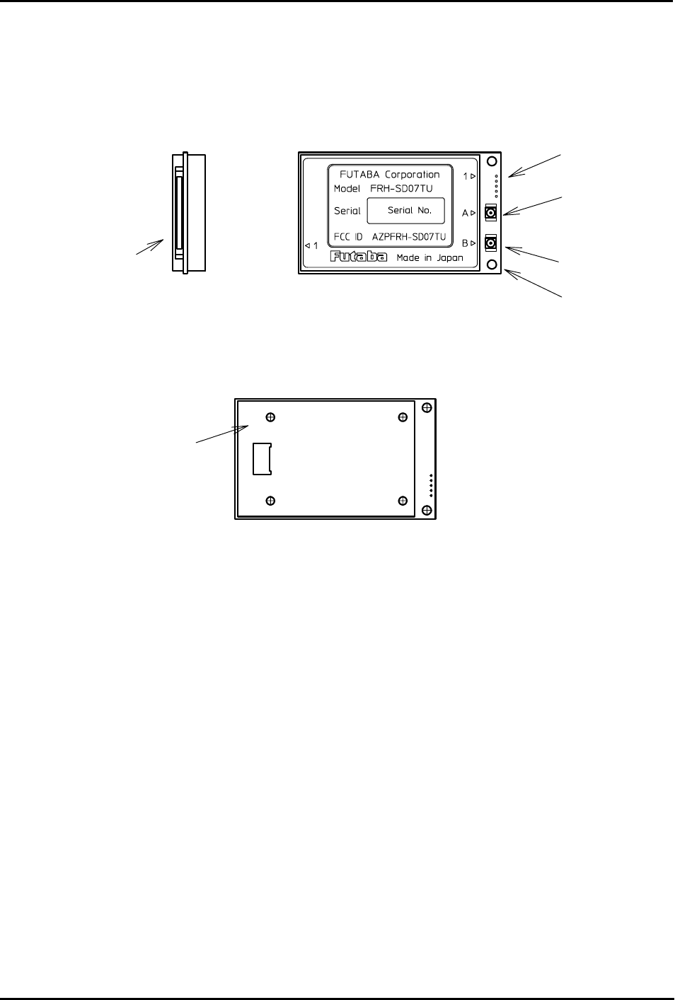
1.5 Physical Description
Please review the following section and take a moment to familiarize yourself with the FRH-
SD07TU/TB wireless modem.
Figure 1–1: Upper View (TU example)
Figure 1–2: Bottom View
(1) Serial Communication Connector
This is a connector to communicate to external terminal equipment (DTE; Data Terminal
Equipment) and connect serial communication cable. Also controlling functions such as
hardware reset and RS232C/RS485 selecting pins are available. Signal is CMOS level. Add
level conversion circuit when level conversion is required.
(2) Antenna Terminal A
Connect Antenna. Install antennas provided by Futaba. If you install single antenna, Antenna
should be installed to this Terminal A.
(3) Antenna Terminal B
This terminal is for diversity reception function. Install second antenna to the terminal B.
(4) AUX Interface Terminal
This terminal is used as auxiliary for the operation. Monitoring statuses such as internal operation,
transmission/receiving operation and antenna diversity switching are available.
Serial
Communication
Connector
Antenna Terminal B
Antenna Terminal A
AUX Terminal
Bottom Mounting Hole
Mounting Hole

Page 6 FRH-SD07TU/TB Manual
Rev. 020510-01
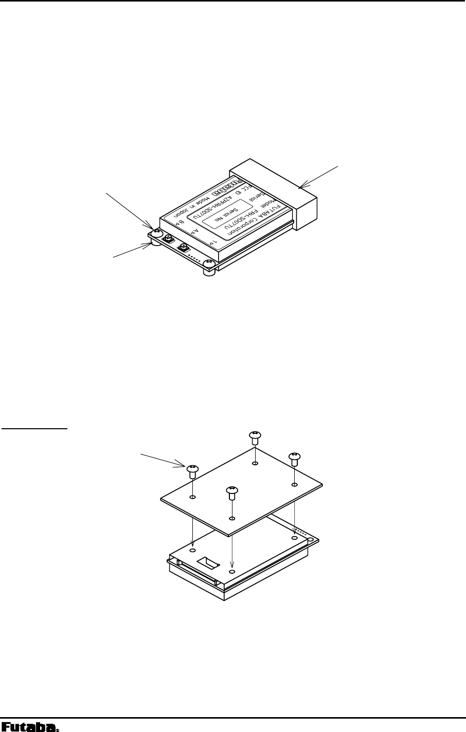
(5) Mounting Hole
The holes are used to install the modem to mounting terminal or bracket. Since screw can be
installed from the front surface, it is easy to install the modem. However, only two holes are
available, it should be fixed by guide structure on the other side of the unit to prevent vibration
problem.
(6) Bottom Mounting Hole
The four holes are used to install the modem. Please use this holes instead of above explained
holes if tightened mounting is required. The hole has M2 taps. Use M2 (ISO) screws that project 2
to 3 mm into the modem. 3.5mm is MAXIMUM LIMIT. Screwing torque is 2.5 kg cm
MAXIMUM.

Page 7
Futaba Corporation Rev. 020510-01
2
SECTION
2 SYSTEM INSTALLATION
CONTENTS
2 SYSTEM INSTALLATION ...................................................................................7
2.1 WIRELESS MODEM INSTALLATION ............................................................................................... 8
2.1.1 Mounting Method 1........................................................................................................... 8
2.1.2 Mounting Method 2........................................................................................................... 8
2.2 COMMUNICATION CABLE CONNECTION........................................................................................ 9
2.3 POWER SUPPLY PRECAUTIONS................................................................................................. 10
2.4 ANTENNA CONNECTION............................................................................................................ 11
2.4.1 Single Antenna Setup..................................................................................................... 11
2.4.2 Diversity Antenna Setup................................................................................................. 12
2.5 OTHER INSTALLATION PRECAUTIONS ........................................................................................ 12
2.5.1 Modem Installation Precautions ..................................................................................... 12
2.5.2 Antenna Installation Precautions.................................................................................... 13
2.5.3 Multiple FRH Modems Installation Precautions ............................................................. 14
Page 8 FRH-SD07TU/TB Manual
Rev. 020510-01
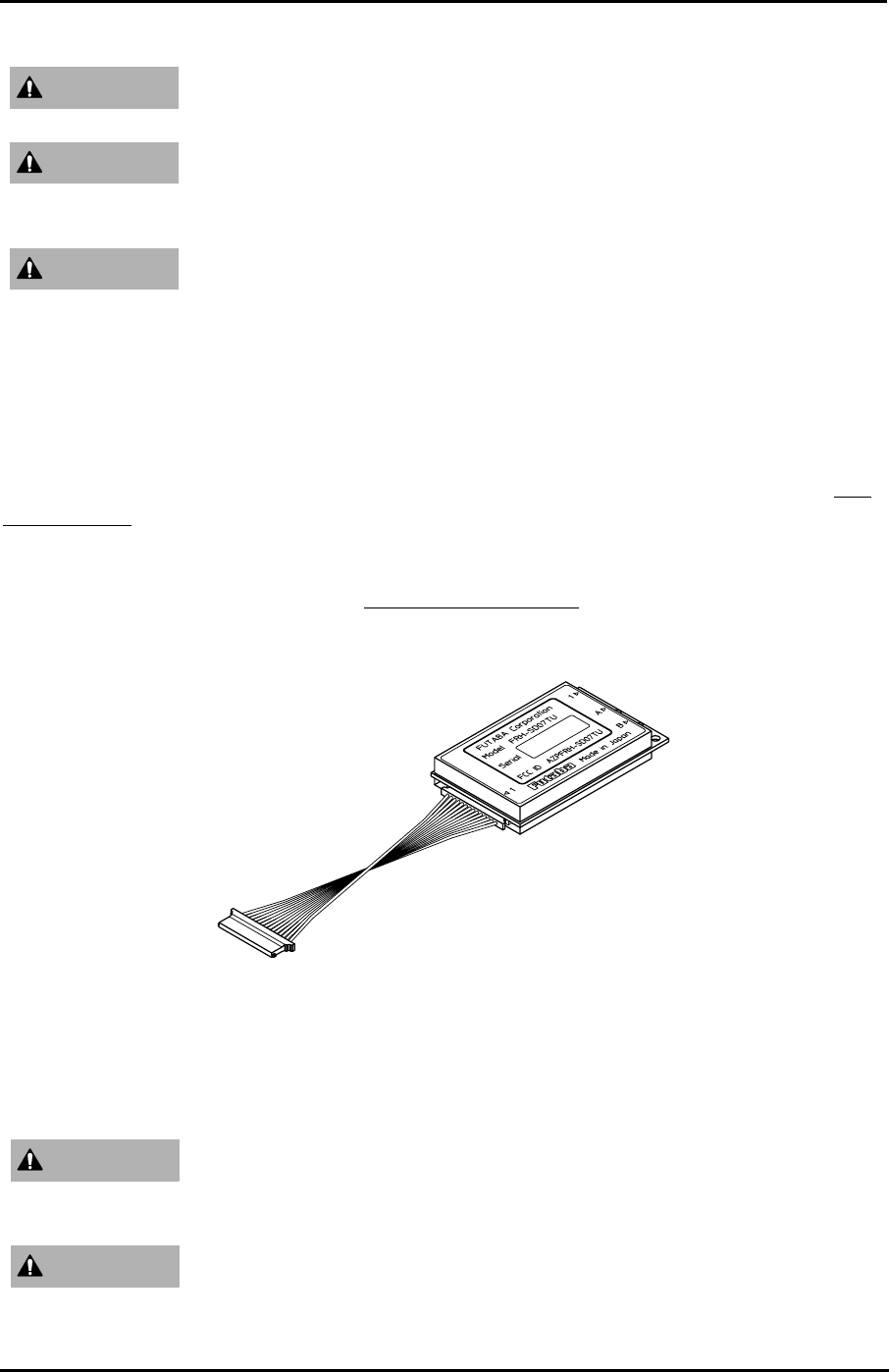
2.1 Wireless Modem Installation
2.1.1 Mounting Method 1
A method to mount the modem directly on a surface using the mounting holes at the side of
the modem’s print circuit board. When using this method, provide a guide on the opposite
side, because two holes are not sufficient to securely mount the modem.
Figure 2–1: Mounting Method 1
2.1.2 Mounting Method 2
To mount the modem using the holes on a flat horizontal surface, which are 3.5mm deep for
M2 screws. When using this method, use M2 screws which project the hole 2 to 3mm deep.
The screw tightening torque is below 2.5kg cm. Mount the modem on a flat plane and be
careful that there is no torsion applied. For the position of the mounting holes, see p.167
DIMENSIONS.
Figure 2–2: Mounting Method 2
Spacer
M2 Screw
Guide
M2 Screw
Page 9
Futaba Corporation Rev. 020510-01
Be careful not to allow water, oil, dust and other foreign particles
(especially metal particles) to enter inside, which may damage the unit.
Since the FRH-SD07TU/TB modem is a precision electronic device,
install it at a place free of excessive shock and vibration to prevent the
unit from damage.
The FRH-SD07TU/TB is designed to be used inside the room. In case
of using it outdoor, be sure to use it within the extent limited by the
environmental specification, and check the ambient temperature and
the state of water-proof.
2.2 Communication Cable Connection
Use the serial communication cable prepared by Futaba to connect the FRH-SD07TU/TB
modem to the external terminal equipment. For the connection of the modem, see p.144 PIN
ASSIGNMENT.
The signal level of the FRH-SD07TU/TB is CMOS. If the interface of the equipment to be
connected is RS232C or RS485, the level conversion circuit is required. For the example of
the level conversion circuit, see p.148 CONVERSION CIRCUIT.
Figure 2–3: Connection of Communication Cable
Be certain that the installer of this equipment reads and understands the
instruction manual of the equipment that is being connected to before
attempting this installation.
Ensure that the FRH-SD07TU/TB modem power and the power to the
equipment to be controlled is turned off before connecting or
disconnecting the cable between them. This will help prevent
WARNING
WARNING
WARNING
WARNING
WARNING

Page 10 FRH-SD07TU/TB Manual
Rev. 020510-01
accidental damage to the system and unexpected operation and/or
injury.
In addition to this manual, read the operation manual of a PC (Personal
Computer) and PLC (Programmable Logic Controller) to be connected.
Be sure to wire the cable connections correctly. Incorrect wiring can
damage the system, causing it to malfunction and/or create a shock and
fire hazard. Also insert the cable firmly to the connector. Since no lock
system is provided with the connector of this equipment, never stretch
the cable or pull it up by hands.
2.3 Power Supply Precautions
Since FRH-SD07TU/TB contains a very-high-frequency sensitive analog circuit, the modem
is susceptible to be affected the variation of the power source and noises from the digital
circuit. Therefore, when embedding the modem into the system, it is necessary to supply
power to the modem from a different (independent) power supply IC chip other than those
used in the digital circuits. Check the noise level from the power source line is enough below
than the practical level in the following way.
• Prepare 2 units of FRH-SD07TU/TB mounted in the system
• Set the frequency of each modem to the same and fixed frequency as below.
Example: @FRQ:H00 CR/LF
• Set the number of retransmission count of the modem on the sender side to 0.
Example: @RNO000 CR/LF
• Issue the @TXT command several hundreds times. If almost all responses are “P0”
(communication success), there is no problem.
• If “N1” response (communication failure) returns many times, there may be a noise
problem in the power source.
• However, there is a possibility of causing communication failure due to a trouble in the
radio communication channel (multipath). For correct judgment, it is recommended to
repeat the above checking several times.
For the operation of commands explained, refer p.79 COMMAND SET
DESCRIPTION.
CAUTION
WARNING
Page 11
Futaba Corporation Rev. 020510-01
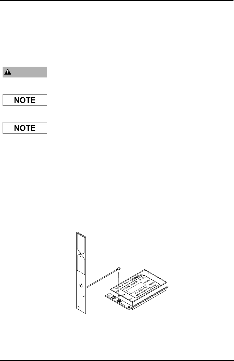
2.4 Antenna Connection
At least one antenna must be connected to Antenna Connector A on each FRH-SD07TU/TB
modem in use. In the environment where multipath fading exists with reliable
communication requirements, a second antenna can be installed to Antenna Connector B for
the diversity reception function to improve reception performance.
Be sure to keep all systems and antennas clear of power lines.
Permanent equipment damage and severe shock injury or death can
occur if the system contacts power lines.
Please contact Futaba before attempting to install any third party
antenna equipment.
Please contact Futaba for information about antenna separation when
using the FRH-SD07TU/TB and other wireless products in the same
area.
2.4.1 Single Antenna Setup
Always use Antenna Connector A when installing a single antenna. Antenna Connector B
cannot be used to transmit and is only used to attach a second receive antenna when the
antenna diversity function is enabled.
Refer to the figures below for details about the actual mounting and connecting methods.
Figure 2–5: Connecting the Antenna
WARNING
Page 12 FRH-SD07TU/TB Manual
Rev. 020510-01
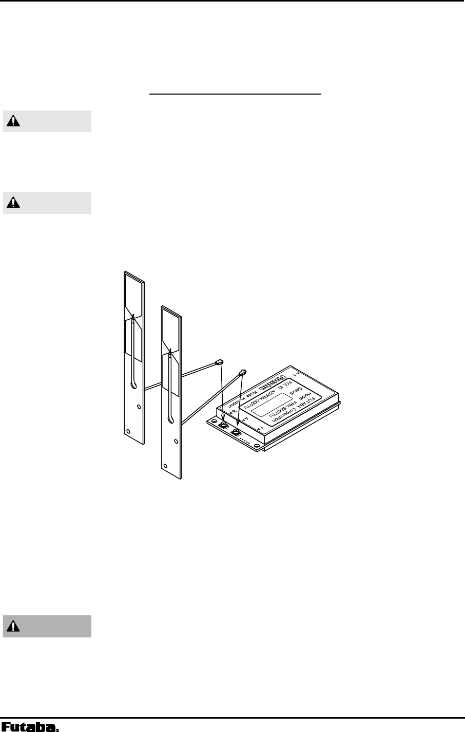
2.4.2 Diversity Antenna Setup
In certain situations, reception can be improved by using the integrated antenna diversity
feature. This is accomplished by using two separate antennas and enabling the diversity
function in REG19 (see p.59 MEMORY REGISTER DESCRIPTION).
When using two antennas with a single modem for diversity
reception, mount the antennas as far apart as possible (at least 6 cm).
If the antennas are too close, the diversity advantage will not be
achieved.
Before connecting the connector, make sure that no dirt and foreign
particles are attached.
Refer to the figures below for details about the actual mounting and connecting methods.
Figure 2–6: Connecting Two Antennas
2.5 Other Installation Precautions
2.5.1 Modem Installation Precautions
Securely attach the antenna cable, and serial communication
connector to the FRH-SD07TU/TB modem and equipment/power
source to which it is connected. Failure to not do so could cause an
unexpected system failure.
CAUTION
CAUTION
WARNING

Page 13
Futaba Corporation Rev. 020510-01
The FRH-SD07TU/TB modem is a precision electronic device. Its
rugged design is intended for industrial applications. However, do not
install it where it will encounter excessive vibrations. In some cases,
isolation mounts may be used to isolate the modem from the
equipment vibration. Excessive vibration could permanently damage
the modem and/or cause it to malfunction.
If the FRH-SD07TU/TB modem has been stored at a temperature
beyond the specified operating temperature range for the system, it
may not function properly. Allow it to return to normal temperatures
before use. Refer to p.165 SPECIFICATION for the actual operating
temperature range.
Do not operate the FRH-SD07TU/TB modem in environments where
it will be subjected to excessive moisture (such as rain or water spray),
dust, oil or other foreign matter (such as metal particles). Doing so
may permanently damage the modem and/or cause it to malfunction. If
it does become wet or contaminated, correct the situation, verify
proper operation and have any problems corrected before using it to
control other equipment. If necessary, the modem can be mounted
inside a protective or waterproof enclosure. If the enclosure is metallic,
the antenna must be mounted externally or the effective operating
range will be severely limited.
The FRH-SD07TU/TB is designed for indoor use. When using it
outdoors, the modem should be mounted in a waterproof enclosure
and the ambient temperature range should be checked to insure that it
is within the modem’s specifications. Always use the modem within
its specified environmental ranges.
2.5.2 Antenna Installation Precautions
Before each use, verify that the antenna (and antenna cable, if used) is
securely attached and in good condition. A loose antenna or cable may
severely reduce the operating range of the system.
Avoid mounting the antenna near large metallic objects or inside metal
enclosures. Such objects can severely reduce the operating range of
the system.
When installing the FRH-SD07TU/TB modem in a mobile unit such
as an Automated Guided Vehicle (AGV), Futaba recommends using
WARNING
WARNING
WARNING
WARNING
WARNING
WARNING
Page 14 FRH-SD07TU/TB Manual
Rev. 020510-01
the diversity reception feature as a remedy for to multipath fading
problems. For diversity reception, install the two antennas as far
apart as possible in order to gain maximum benefit (Actual
recommendation is 30 cm, 6 cm at least).
FUTABA standard antenna is made by Printed Circuit Board. It is not
fabricated for severe use. Please use antenna without any unexpected
force (bent or broken). Mount the antenna in a location where it will
be least likely to be damaged by contact with other objects or
equipment.
The FRH-SD07TU/TB operates at frequencies in the 2.4 GHz band.
These frequencies are much directional than lower frequencies and are
easily reflected. If there are metal structures nearby, the effective
range may be shortened or the directional properties may be further
narrowed. To help avoid this, mount the antenna as far away as
possible from surrounding metallic structures.
Multipath problems occur easily at 2.4 GHz frequencies. When
multipath problems are present, moving the antenna as little as 10 cm
may result in improved communication or, conversely, a further
diminished or total loss of communication. Futaba recommends that
the mounting position of the antenna be determined after testing and
verifying optimal communication conditions. Negative multipath
effects can also be overcome with antenna diversity. See p.12
DIVERSITY ANTENNA SETUP and the related register settings for more
details regarding antenna diversity.
2.5.3 Multiple FRH Modems Installation Precautions
When installing multiple FRH (series) modem systems that will use
different frequency groups in the same area, modem’s antennas of
different frequency groups must be mounted at least 6 feet (2
meters) apart. Failure to do so may severely reduce the modem
operating range.
Please contact Futaba for information about antenna separation when
using the FRH-SD07TU/TB and other wireless products in the same
area.
CAUTION
CAUTION
CAUTION
CAUTION

Page 15
Futaba Corporation Rev. 020510-01
2.5.4 ID Code Setting Recommendation
Futaba recommend user to set unique ID code to prevent unexpected
interference (jamming) between individual FRH systems working in
the same area.
The protocol on RF channel employed in FRH series modem is
Futaba’s original protocol. Therefore, there is no concern undesired
connection to other radio systems, such as wireless LAN. On the other
hand, it has a possibility that unexpected, undesired radio connection
between Futaba’s FRH series modems which work as different radio
systems.
To prevent this undesired radio connection, ID code (REG04 and
REG05) can be used. Since the FRH radio modems which set different
ID code can not communicate each other, it is possible to prevent an
undesired connection.
Set same ID code to the modems work in the same radio system. Set
appropriate and individual ID code for the system, do not use simple
code such as 1111H, not to coincide to other system’s setting.
Refer to p.157 PREVENTING UNDESIRED RADIO CONNECTION in this
manual for details.

Page 17
Futaba Corporation Rev. 020510-01
3
SECTION
3 SYSTEM OPERATION
CONTENTS
3 SYSTEM OPERATION ......................................................................................17
3.1 OPERATION MODES ................................................................................................................. 18
3.1.1 Mode 3 – Packet Transmission Mode............................................................................18
3.1.2 Mode 4 – Repeater Mode............................................................................................... 18
3.1.3 Mode 5 – Headerless Packet Transmission Normal Mode............................................18
3.1.4 Mode 6 – Direct Transmission Mode.............................................................................. 19
3.2 PACKET TRANSMISSION MODE.................................................................................................. 20
3.2.1 Packet Transmission Mode Protocol.............................................................................. 20
3.2.2 Broadcast Transmission Protocol................................................................................... 21
3.2.3 Transmit Command and Receive Header...................................................................... 22
3.2.4 Extended Receiving........................................................................................................ 24
3.2.5 Communication Time in Packet Transmission Mode ..................................................... 26
3.2.6 Precautions in Packet Transmission Mode ....................................................................30
3.3 POWER DOWN MODE ............................................................................................................... 33
3.4 FREQUENCY GROUPING ........................................................................................................... 35
3.4.1 Frequency Band ............................................................................................................. 35
3.4.2 Frequency Allocation......................................................................................................35
3.4.3 Frequency Group Operation........................................................................................... 36
3.4.4 Grouping Methods..........................................................................................................36
3.4.5 Grouping Method Details................................................................................................ 37

Page 18 FRH-SD07TU/TB Manual
Rev. 020510-01
3.1 Operation Modes
FRH-SD07TU/TB modem can operate in one of four primary operation modes. Select the
mode that best suits your specific application. The default setting is Mode 3. Mode 1 and 2
are the modes perform on the other FRH series modem.
Mode Protocol Function
3 Modem
4 Repeater
5
packet
transmission
6 direct transmission Modem
Table 3–1: FRH Operation Modes
3.1.1 Mode 3 – Packet Transmission Mode
• In Mode 3, the FRH-SD07TU/TB modem communicates in packet transmission
mode. Communication parameters are set using the memory registers.
• Mode 3 is generally used for 1:n and n:m wireless network topology and for applications
in which the volume of data is relatively small and changing the destination station
occurs frequently.
3.1.2 Mode 4 – Repeater Mode
• In Mode 4, the FRH-SD07TU/TB modem operates as a repeater in packet
transmission mode. All modem and communication parameters are controlled through
the modem’s internal memory registers.
• Mode 4 is used to extend the effective communication range in a topology using Mode 3.
3.1.3 Mode 5 – Headerless Packet Transmission Normal Mode
• Mode 5, a special mode in packet transmission mode, is used by no transmission
command required in Mode 3 and enable transmission only by the direct data input.
• Mode 5 is generally used for 1:n wireless network topology and for applications in
which the volume of data is relatively small and changing the destination station from
among the receiver modems occurs infrequently. Since no transmission command is
required, the development of upper layer application program becomes easier.
• The operation method of Mode 5 is quite different from that of Mode 3 and Mode 4.
For details, refer to p.118 HEADERLESS PACKET TRANSMISSION MODE.

Page 19
Futaba Corporation Rev. 020510-01
3.1.4 Mode 6 – Direct Transmission Mode
• Mode 6 is a mode to transmit input data not as the data-bit but as the signal level
indicating high or low state.
• Mode 6 features a short transmission delay of about 500 us due to no need to assemble
data to the wireless packet.
• Mode 6 is particularly suitable for, an upper layer application where fast response is
required.
• The operation method of Mode 6 is quite different from that of Mode 3 through Mode 5.
For details, refer to p.127 DIRECT TRANSMISSION MODe.

Page 20 FRH-SD07TU/TB Manual
Rev. 020510-01
3.2 Packet Transmission Mode
Packet transmission mode operates as half-duplex communication and requires explicit
commands to control the modem transmissions. Because this mode allows the addressing of
different destination receiver modems by embedding the address in the data packets, it is
best suited for 1:n and n:m topology applications.
In packet transmission mode, the FRH-SD07TU/TB modem normally waits in a ready-to-
receive state.
When a transmission command is issued to the sender modem from its terminal equipment,
the modem searches for a clear frequency channel and, when found, transmits the message to
the intended destination receiver modem.
Packet transmission mode also allows expansion of the effective wireless communication
range by using an additional FRH (series) modem configured as a repeater.
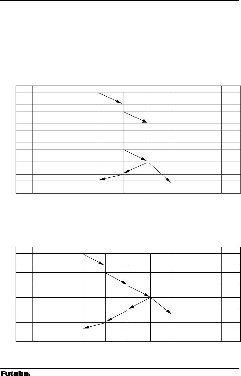
3.2.1 Packet Transmission Mode Protocol
In packet transmission mode, after a data packet is transmitted from the sender modem
(station) to a destination station, the destination station acknowledges successful
communication by returning an acknowledgement (ACK) packet to the sender modem.
The sender modem waits for the ACK packet and when it is received, indicates that the
transmission was successful. If it does not receive an ACK packet, it will continue to
retransmit the data packet until it does receive an ACK packet or until the retransmission
count (REG11 or RNO command setting) reaches the preset limit. If the sender modem
receives an ACK packet anytime during the retransmission attempts, it returns a
“successive completion response” (P0) code to its terminal equipment. If the modem
does not receive an ACK packet, it returns a “transmission failed” (N1) code to its
terminal equipment.
Sender Modem Destination Modem
Figure 3–2: Packet Transmission and ACK response
Data Transmission
ACK response
Page 21
Futaba Corporation Rev. 020510-01
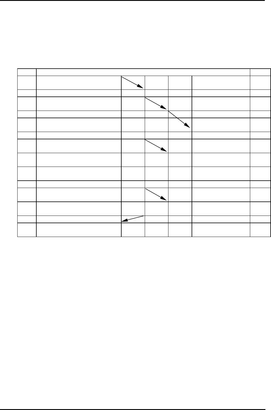
3.2.2 Broadcast Transmission Protocol
Broadcast transmission (sending the same data to multiple modems simultaneously) is
possible in packet transmission mode by setting 255 as the destination address
(REG02). However, because ACK packet are not returned when executing the broadcast
transmission, the sender modem does not receive confirmation of the “successful reception”
of the transmitted data from any of the receiver modems.
In broadcast transmission, the sender modem transmit the data packet the number of times
equal to the preset retransmission count (REG11 or RNO command setting) plus one
and then it outputs a successive completion response (P0) to its terminal equipment.
When the remote receiver modems receive the transmitted data successfully, they output the
data to their terminal equipments normally and do not return ACK packet. Once a valid data
packet has been received correctly by a receiver modem, rest of data received during any
subsequent retransmissions are discarded and not output to its terminal equipment.
Sender Modem Remote Modem
Figure 3–3: Broadcast Transmission
Data Transmission
Retransmission
Retransmission
Retransmission
・
・
・
End

Page 22 FRH-SD07TU/TB Manual
Rev. 020510-01
3.2.3 Transmit Command and Receive Header
Four transmit commands can be used in packet transmission mode (mode 3). Both text
and binary data can be sent directly from modem-to-modem or sent through a third FRH
(series) modem configured as a repeater. The receiver modem automatically determines the
transmitted data format and communication path from the information in the received packet
header. Refer to the table below for a list of the transmit commands and the corresponding
header component.
Transmit Command Receive Header Function
TXT RXT Text data transmission
TBN RBN Binary data transmission
TXR RXR Text data transmission via repeater
TBR RBR Binary data transmission via repeater
Table 3–5: Transmit Commands and Receive Headers
The following list shows each command’s syntax as issued at the sender terminal equipment
and the response displayed at the receiver terminal equipment when the packet is received.
1. Direct Text Data Transmission
transmit:
@TXT [destination address]{source address}[message]
receive: RXT [source address][message] CR/LF
2. Direct Binary Data Transmission
transmit: @TBN[destination address]{source address}[message length][message] CR/LF
receive: RBN [source address][message length][message] CR/LF
3. Text Data Transmission through Repeater
transmit: @TXR [repeater address][destination address]{source address} [message] CR/LF
receive: RXR [repeater address][source address][message] CR/LF
4. Binary Data Transmission through Repeater
transmit:
@TBR [repeater address][destination address]{source address}
[message length][message]
CR/LF
receive: RBR [repeater address][source address][message length][message] CR/LF
where {source address} is optional, used in RS485 mode set by serial communication cable
12 pin.
The following list defines the parameters and symbols used in the commands above:
@ = command header
CR/LF = carriage return + line feed
destination address = address of modem to receive the message (000 to 239)

Page 23
Futaba Corporation Rev. 020510-01
source address = address of modem sent the message (000 to 239)
repeater address = address of the repeater modem (000 to 239)
message length = number of bytes in message
message = information data (255 bytes or less)
Since there are significant notes for issuing the transmit command, be
sure to read p.158 OPERATION IMPORTANT NOTICE.
In the text data transmission, the message is considered to be
terminated when the CR/LF code appears in it. No data after that will
be transmitted. When the CR/LF code contains in a message, use the
binary data transmission command.
When the command header contains in a message data, the data
after that are recognized as the command, resulting in command
error. When the command header contains in a message data, it is
necessary to set the memory register REG15, Command
Recognition Interval.
CAUTION
CAUTION
CAUTION
Page 24 FRH-SD07TU/TB Manual
Rev. 020510-01
3.2.4 Extended Receiving
The extended receiving function (mode 3 and 5) can be used to prevent the degradation of
transmission delay or failure caused by a collision of two transmission packet where two
modems perform transmission at the same time in the contention topology application. The
collision results retransmission of the same packet or packet transmission failure. Set with
the memory register REG19: bit 3 to enable this function.
3.2.4.1 Operation of Extended Receiving
In the transmission originate sequence, the message packet arrived during carrier sensing in
the sequence is not received all but carrier sensing continues. But in the extended
receiving, the message packet arrived during carrier sensing is received and the modem
returns ACK packet. After returning ACK, carrier sensing resume.
The following is the operation of packet transmissions which is invoked both of the two
modems simultaneously while the extended receiving function is valid.
Fig. 3–5: Operation of Extended Receiving
1. Modems 1 and 2 transmit messages packet at the same time.
2. Both modems wait for ACK but the status becomes time-out.
3. Both modems start random wait after the transmission, and the modem first
completes the random wait starts carrier sensing and retransmits the message.
(in this case, modem 2)
4. Modem 1 receives the retransmitted message during carrier sensing state
(performs the extend receiving), return ACK after receiving the message.
5. Modem 1 does carrier sensing again and transmits the message.
6. Modem 2 returns ACK to complete transmission.
message
transmission
message
transmission
simultaneous
transmission
wireless modem 2
il
wireless modem 1
il
ACK
ACK

Page 25
Futaba Corporation Rev. 020510-01
3.2.4.2 Caution for Extended Receiving
As understood from the figure above, the modem 1 outputs to the terminal equipment as
follows.
P1 CR/LF response of transmission command acceptance
RXT002 . . . . CR/LF message output
P0 CR/LF response of successive transmission
Therefore, it is necessary to design an upper layer application protocol with a consideration
that the message is output between the command responses “P1” and “P0”. Except the
headerless packet transmission mode, such consideration is not necessary because there
is no “P1” and “P0” response.

Page 26 FRH-SD07TU/TB Manual
Rev. 020510-01
3.2.5 Communication Time in Packet Transmission Mode
3.2.5.1 Transmission sequence
The transmission sequence in the packet transmission mode (mode 3,4 and 5) and time
required for each transmission are described as follows:
1. Issue the transmission command
The input time of the transmission command is determined by the serial communication
parameter between the terminal equipment and the modem. Relating parameters are as
follows.
a. transmitting rate (300 bps to 115200 bps)
b. data length (7 or 8 bits)
c. parity bit (with or without)
d. stop bit length (1 or 2 bits)
e. start bit length (1 bit constant)
Example: In the case of the transmitting rate of 9600 bps, 1 start bit and 1 stop bit,
data length of 8 bits and without parity, the time required for sending 1 byte is
1.04 ms, as 104 us is required for 1 bit.
To transmit 10 bytes message data by the TXT command, the command syntax is
@TXT001ABCDEFGHIJ CR/LF of 19 bytes, requiring 19.8 ms.
2. Carrier sensing
The sensing time to confirm whether another modem is transmitting or not. If a carrier is
detected during carrier sensing, again another carrier sensing will take place after
random wait time.
3. Wireless transmission
The wireless transmission time depends on the message byte data length (1 to 255).
It can be expressed in the following equation.
7.084 ms + message byte x 0.154 ms
4. Waiting for ACK packet
The time for waiting ACK packet after the end of wireless transmission. It takes 5 ms
for the direct transmission to the destination station and “wireless transmission time +
17.2 ms” for the transmission through repeater. If the preamble of the ACK packet
cannot be received within this period, it results transmission failure. When the
retransmission count (REG11 or RNO command setting) does not reach 0, carrier
sensing starts after the random wait time. When the retransmission counter reaches
0, the transmission ends with the “N1” response of transmission failure.
5. Transmission of ACK (NAK)
The time for transmitting the response packet from the receiver modem. ACK packet is
Page 27
Futaba Corporation Rev. 020510-01
to notify the sender the successful receiving. NAK packet is to notify the receive failure
which the repeater returns to the sender modem when no respond from the destination
station, in case the transmission is through the repeater. In both cases, it takes
7.084 ms.
6. Random wait
When a carrier is detected in carrier sensing or data are retransmitted due to
transmission failure, carrier sensing starts after the randomly set wait period for to
prevent the collision of packets. It takes 0, 3, 6 or 10 ms, random wait time
7. Output of received data
Time to output the received data to the terminal equipment. This time depends on the
serial communication parameter between the terminal equipment and the modem, as in
the case of above ISSUE THE TRANSMISSION COMMAND.
3.2.5.2 Communication time
An example of the communication time for transmitting 10 bytes message with 1 stop bit and
without parity, where the communication parameter is 19200 bps and the data length is 8 bits,
is shown below.
Case 1: Successive finish of the TXT command
This case is the most basic communication example.
Time Terminal 1 Modem 1 Modem 2 Terminal 2 Time
10ms Issue transmission
command
3ms carrier sensing
9ms Transmission
Receiving
7ms receive ACK ACK transmission
received data output 10ms
2ms response
Total
31ms
Page 28 FRH-SD07TU/TB Manual
Rev. 020510-01
Case 2: Finish by one-time retransmission of the TXT command
This example is a case of one-time retransmission. Since no ACK is received,
the modem retransmits the data. In the retransmission routine, random wait
for 10 ms to prevent the collision of packets and carrier sensing starts again.
The subsequent communication is the same as the Case 1.
Time Terminal 1 Modem 1 Modem 2 Terminal 2 Time
10ms Issue transmission
command
3ms carrier sensing
9ms Transmission
5ms wait for ACK (no response)
10ms random wait
3ms carrier sensing
9ms Transmission
Receiving
7ms receive ACK ACK transmission
received data output 10ms
2ms Response
Total
58ms
Case 3: Successive finish of the TXR command
This example is the transmission through the repeater. In the transmission through
the repeater, it takes twice longer for the wireless communication because of the
data is transferred by the repeater.
Time Terminal 1 Modem 1 Repeater Modem 2 Terminal 2 Time
11ms Issue transmission
command
3ms carrier sensing
9ms Transmission to the
repeater
9ms Transmission from
the repeater Receiving
7ms ACK received by
the repeater ACK transmission
received data output 11ms
7ms receive ACK from
the repeater
4ms Response
Total
50ms
Page 29
Futaba Corporation Rev. 020510-01
Case 4: Successive finish of broadcasting the TXT command
This example shows the case of broadcast transmission. In the broadcast
transmission, data are retransmitted by the specified times. If the receiver modem
has once received it, the retransmitted data will not be output to the terminal
equipment.
Time Terminal 1 Modem 1 Modem 2 Terminal 2 Time
10ms Issue transmission command
3ms carrier sensing
9ms Transmission
Receiving
5ms wait time output received data 10ms
10ms random wait
3ms carrier sensing
9ms Transmission
Receiving
5ms wait time No output since the
date is the same data
10ms random wait
3ms carrier sensing
9ms wireless transmission
wireless receiving
5ms wait time No output since the
date is the same
2ms response
Total
83ms

Page 30 FRH-SD07TU/TB Manual
Rev. 020510-01
3.2.6 Precautions in Packet Transmission Mode
3.2.6.1 No ACK Response
In packet transmission mode (mode 3), succession of communication is confirmed when
the sender modem receives an acknowledgment (ACK packet) from the receiver modem. If
the ACK packet is not successfully obtained from the receiver modem, even though the data
was successfully received, the sender modem concludes (incorrectly) that the data
transmission sequence was failed and outputs transmission failure response (N1) to its
terminal equipment. The following text describes what will occur in such situations:
When the ACK packet is lost and the retransmission count (REG11 or RNO command
setting) is set to 0:
Tx modem: sends packet
Rx modem: transmits ACK and outputs the received data to its terminal equipment
Tx modem: outputs the transmission failure response (N1) to its terminal equipment
(since no ACK was received) and takes no more action.
When the ACK packet is lost and the retransmission count set to 1 or greater:
Tx modem: sends packet
Rx modem: transmits ACK and outputs the received data to its terminal equipment.
Tx modem: retransmits same packet until ACK is received or until it finishes
retransmission of the packet the number of times the retransmission count
plus one
Rx modem: for each subsequent data packet successfully received, transmits an ACK but
does not forward the again-received-data to its terminal equipment
Tx modem: if an ACK is received after any retransmission attempt, a successive
completion response (P0) returns to its terminal equipment; otherwise, the
transmission failure response (N1) returns
Problems with ACK packet not being received can usually be resolved by increasing the
number of retransmission count setting. However, if in the situation above, inconsistency
of data stream perception between sender and receiver terminal equipments will occur. This
problem can not be resolved in the modem inside, prepare the solver in the upper layer
application protocol.
3.2.6.2 Throughput Degradations in Frequency Grouping
If the retransmission count is not set sufficiently high when using the frequency group
function in the packet transmission mode (modes 3 and 5), receive throughput will drop
and the probability of transmission failure will increase. To help alleviate these potential
performance problems when using the frequency group function, set the retransmission
count to a value equal to or larger than the square of the number of frequencies being used.

Page 31
Futaba Corporation Rev. 020510-01
Receive throughput will drop since the frequency between the sender modem and receiver
modem is not identical in some case (because multiple frequencies are used). When using the
frequency group function, receiver modems are in the ready-to-receive state and is
sequentially changing frequencies. A sender modem, that has data to be transmitted, also
transmits its packet sequentially with changing frequencies until it receives ACK from the
receiver modem or until it reaches the retransmission count plus one. Because the
receiving modem changes frequencies at a slower rate than the transmitting modem, the both
frequency channels will eventually align. And the data packet will be successfully
transmitted. To make frequency alignment in both mode, the retransmission count should
be set high enough. But sometimes, it takes a time to make this alignment.
The use of the frequency group function is effective when specific frequencies are
interfered, but will result a degradation of data throughput. Accordingly, it is recommended
to use the fixed frequency mode for applications that require high data throughput in the
packet transmission mode. (In this case, the communication may be susceptible to
interference or multipath fading)
3.2.6.3 Collision Avoidance in RS485 Interface
When multiple modems are connected on RS485 wire-line, the received data or the
command responses of the modem may collide on the line. Reasons of such collision are
that multi-dropped multiple modems receive packet at the same time and output to RS485
line, or, multiple modems accept global addressing command and output its response at
the same time.
When there is a possibility of the RS485 line collision, avoid it by taking following remedy.
1) Set each of the multi-dropped modem’s Interval between packets (REG07) value to
different value. Difference between each set value shall be larger than 1 byte transmission
duration (from the start bit to the stop bit) which determined by the RS485 line baud rate.
2) Set the Collision avoidance function (REG23:bit 1) of all modems to 1.
3) Set Regular interval output for RS485 collision avoidance (REG23:bit 2) to 1 of the
modem which Interval between RS485 packets (REG07) is set to the longest
The above remedy is set to the multiple modems that are multi-dropped, the modem which
set REG07 interval to the longest outputs regularly CR code [0DH] when all modem has no
data to output. This enables timing synchronization of all of the modems to start measuring
the interval time between RS485 data packets to packet.
This results that data will not be output from multiple modems at the same time since the
interval between RS485 packets (REG07) of each modem is set to different values. Also
the modem can detects another station’s RS485 data transmission status since the interval
difference is set more than 1 byte time. Eventually, this can avoid collision on the RS485 line
since the modem can wait for their turn to output RS485 data.

Page 32 FRH-SD07TU/TB Manual
Rev. 020510-01
3.2.6.4 Retransmit Count in Broadcast Transmission
In the broadcast transmission, the modem does transmit packet up to the retransmission
count (REG11 or RNO command setting). If the upper layer application protocol is
designed, such that the receiver side terminal equipment immediately return the response to
the sender, the reply is sent back during retransmission is in progress. In this case, the reply
packet cannot be received during the retransmission. It is necessary to set the
retransmission count to a suitable value in the case.

Page 33
Futaba Corporation Rev. 020510-01
3.3 Power Down Mode
The FRH-SD07TU/TB has three power down modes. Select the mode according to the
power supply operating conditions such as battery powered application.
(1) Active Mode
This mode is not the power down mode but always capable of transmitting and receiving
data. The modem is in the active mode when the power is turned on.
The current consumption is 35 mA maximum in this mode.
(2) ULTRA Mode
ULTRA (Ultra Low Power Transient Radio Access) mode is the doze mode. When set
to the ULTRA mode, the modem transits to the intermittent receive state to wait the
wakeup request packet. On receipt of the wakeup request packet to be requested
wakeup from other modem, the modem returns to the Active mode to operate normal
communication operation. This mode is effective, by extending the operation duration time,
in the operation using the power source with limited capacity, such as dry-batteries or solar-
batteries.
The average current consumption is about 2 mA in this mode.
(3) RF Block Power Down Mode
This mode shuts down the power supply of the RF circuit block, where only the control
(logic) circuit is activating. Since the control circuit is in operation, the setting of memory
registers are retained. When the modem returns to the Active mode, it can continue its
operation since the register value is retained. Furthermore, functions such as referencing and
setting memory registers can be used in this mode.
This mode is invoked by the following commands.
ROF command: to become the RF block power down mode
RON command: to return to the Active mode
The current consumption is about 5 mA in this mode.
(4) Shutdown Mode
This mode not only shuts down the power source of the RF circuit block but also stops the
control (logic) circuit operation. The current consumption becomes minimum. Since the
control circuit does not operate in this mode, the modem will be in the reset state when it
returns to the Active mode. That is, all parameters, tentatively change modem operation like
FRQ command, will be initiated. On the other hand, memory register parameters set by
the REG command is effective.
This Shutdown mode is the same state as the system reset and can be used as the ‘forced
reset’ from the terminal equipment. Reset duration (initializing) time when power is turned
on is about 220 ms. However, returning from this mode can accept commands in about 75 ms.
Set with Pin 11 (/SHUT) of the serial communication interface.
To set Pin 11 to ‘L’: to the Shutdown mode
To set Pin 11 to ‘H’: to return to the Active mode

Page 34 FRH-SD07TU/TB Manual
Rev. 020510-01
If the modem transits to the Shutdown mode from the ULTRA mode, it will return to the
ULTRA mode again when the Shutdown mode is released.
The current consumption is about 70uA in this mode.

Page 35
Futaba Corporation Rev. 020510-01
3.4 Frequency Grouping
3.4.1 Frequency Band
The FRH-SD07TU/TB has 54 individual frequencies between 2420 MHz and 2479 MHz
with 1 MHz / 2MHz separation in each frequency. One system can select/operate 24
frequencies in the 54 frequencies. See the table below for the exact frequency assignments.
3.4.2 Frequency Allocation
24 Frequency are assigned each frequency band (01, 02 and three 2 MHz separation) with 1
MHz or 2 MHz separation. If 1 MHz adjacent frequency separation is utilized in a same area,
the possibility of adjacent channel interference exists because the difference of reception
signal level between the desired signal and undesired leakage from the adjacent channel.
Specially, if fixed (single) frequency operation, more than 2 MHz separation operation is
recommended. *Both France and Spain are band limited, please use 02 Band for operation.
Freq. (MHz)
Freq. No. 2433-79MHz 01 Band 02 Band* 2420-66MHz 2423-69MHz
0 2433 2426 2450 2420 2423
1 2435 2427 2451 2422 2425
2 2437 2428 2452 2424 2427
3 2439 2429 2453 2426 2429
4 2441 2430 2454 2428 2431
5 2443 2431 2455 2430 2433
6 2445 2432 2456 2432 2435
7 2447 2433 2457 2434 2437
8 2449 2434 2458 2436 2439
9 2451 2435 2459 2438 2441
10 2453 2436 2460 2440 2443
11 2455 2437 2461 2442 2445
12 2457 2438 2462 2444 2447
13 2459 2439 2463 2446 2449
14 2461 2440 2464 2448 2451
15 2463 2441 2465 2450 2453
16 2465 2442 2466 2452 2455
17 2467 2443 2467 2454 2457
18 2469 2444 2468 2456 2459
19 2471 2445 2469 2458 2461
20 2473 2446 2470 2460 2463
21 2475 2447 2471 2462 2465
22 2477 2448 2472 2464 2467
23 2479 2449 2473 2466 2469
Table 3–6: Frequency Table

Page 36 FRH-SD07TU/TB Manual
Rev. 020510-01
3.4.3 Frequency Group Operation
The FRH-SD07TU/TB can operate on a fixed frequency or on any frequency in a set of
frequency group.
Multiple FRH (series) systems can be use different frequency groups and operate in the
same area without mutual interference between the systems. When the RF environment is
relatively clean, wireless channel links can be made on a fixed, clear frequency (no
interference) by using Grouping Method H. In less than ideal RF environments, it is better
to use multiple frequencies method in the frequency group (Grouping Method A through
G, multi-Access function). Since the modem searches clear frequency in the group, it
overcomes multipath fading and interference problems and establishes wireless
communications.
On the down side, wireless link establishment delays will become longer when using the
frequency group function (multi-access function) because the additional time is required
for searching the channels in the group with transmitting and receiving the packet on the both
end of the modem. The average connection delay will increase and the number of systems
that can operate independently in the same area will decrease as the number of frequencies
per group increases. Select the best grouping method for your application.
3.4.4 Grouping Methods
The frequency grouping method and group number are set using memory register
REG06.
The following eight frequency grouping methods are available:
Method Number of
Groups Group Numbers Frequencies
per Group
A 1 0 24
B 2 0 to 1 12
C 3 0 to 2 8
D 4 0 to 3 6
E 6 0 to 5 4
F 8 0 to 7 3
G 12 0 to 11 2
H 24 0 to 23 1
Table 3–7: Frequency Grouping Methods and Group Numbers
• In Grouping Method A, multi-access function uses all 24 frequencies.
• Frequencies are fixed in Grouping Method H, because only one frequency is available
in each group.

Page 37
Futaba Corporation Rev. 020510-01
3.4.5 Grouping Method Details
Group Frequency Numbers
0 All frequencies from 0 to 23
Table 3–8: Grouping Method A (1 group; 24 frequencies)
Group Frequency Numbers
0 0, 2, 4, 6, 8, 10, 12, 14, 16, 18, 20, 22
1 1, 3, 5, 7, 9, 11, 13, 15, 17, 19, 21, 23
Table 3–9: Grouping Method B (2 groups; 12 frequencies each)
Group Frequency Numbers
0 0, 3, 6, 9, 12, 15, 18, 21
1 1, 4, 7, 10, 13, 16, 19, 22
2 2, 5, 8, 11, 14, 17, 20, 23
Table 3–10: Grouping Method C (3 groups; 8 frequencies each)
Group Frequency Numbers
0 0, 4, 8, 12, 16, 20
1 1, 5, 9, 13, 17, 21
2 2, 6, 10, 14, 18, 22
3 3, 7, 11, 15, 19, 23
Table 3–11: Grouping Method D (4 groups; 6 frequencies each)
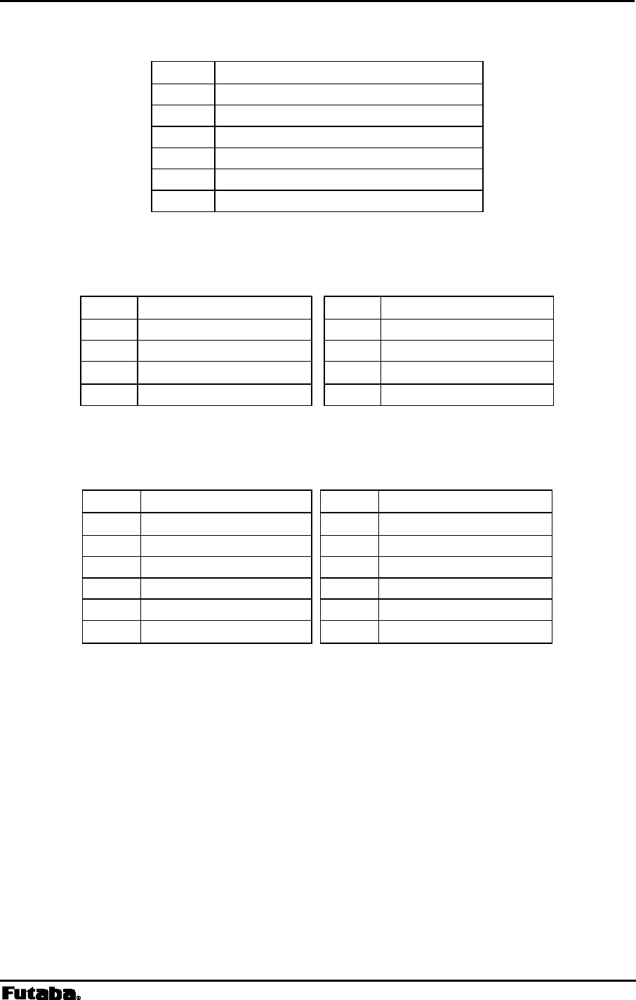
Page 38 FRH-SD07TU/TB Manual
Rev. 020510-01
Group Frequency Numbers
0 0, 6, 12, 18
1 1, 7, 13, 19
2 2, 8, 14, 20
3 3, 9, 15, 21
4 4, 10, 16, 22
5 5, 11, 17, 23
Table 3–12: Grouping Method E (6 groups; 4 frequencies each)
Group Frequency Numbers Group Frequency Numbers
0 0, 8, 16 4 4, 12, 20
1 1, 9, 17 5 5, 13, 21
2 2, 10, 18 6 6, 14, 22
3 3, 11, 19 7 7, 15, 23
Table 3–13: Grouping Method F (8 groups; 3 frequencies each)
Group Frequency Numbers Group Frequency Numbers
0 0, 12 6 6, 18
1 1, 13 7 7, 19
2 2, 14 8 8, 20
3 3, 15 9 9, 21
4 4, 16 10 10, 22
5 5, 17 11 11, 23
Table 3–14: Grouping Method G (12 groups; 2 frequencies each)
Page 39
Futaba Corporation Rev. 020510-01
Group Frequency Numbers Group Frequency Numbers
0 0 12 12
1 1 13 13
2 2 14 14
3 3 15 15
4 4 16 16
5 5 17 17
6 6 18 18
7 7 19 19
8 8 20 20
9 9 21 21
10 10 22 22
11 11 23 23
Table 3–15: Grouping Method H (fixed frequency mode)
The initial value of the memory register is Group 0 of the Grouping
Method F. (3 frequencies of 8 group modes)
To test the communication initially, use the Grouping Method H
(fixed frequency mode) at first. Operation at frequency grouping
mode makes the communication quality robust against multipath
fading and interference, but sometimes leads to degrade throughput or
transmission failure.

Page 41
Futaba Corporation Rev. 020510-01
4
SECTION
4 FUNCTION CONTROL METHODS
CONTENTS
4 FUNCTION CONTROL METHODS...................................................................41
4.1 FUNCTION CONTROL METHODS ................................................................................................ 42
4.1.1 Serial Interface Setting ................................................................................................... 42
4.1.2 Memory Register Setting................................................................................................43
4.1.3 Memory Register Initialization ........................................................................................ 44
4.2 COMMAND CONTROL................................................................................................................ 46
4.2.1 Command Entry.............................................................................................................. 46
4.3 COMMUNICATION METHODS ..................................................................................................... 47
4.3.1 Communication Example (1:1 – Mode 3).......................................................................47
4.3.2 Communication Example (1:n – Mode 3).......................................................................49
4.3.3 Communication Example (n:m – Mode 3)......................................................................51
4.3.4 Repeater Example (Mode 4) .......................................................................................... 54
4.3.5 Other Communication Configurations ............................................................................ 57
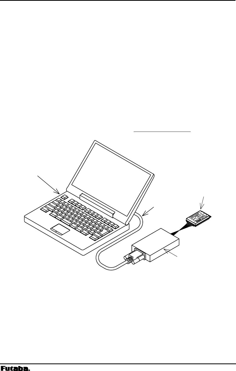
Page 42 FRH-SD07TU/TB Manual
Rev. 020510-01
4.1 Function Control Methods
4.1.1 Serial Interface Setting
For connecting the FRH-SD07TU/TB modem with an external terminal equipment, RS232C
is appropriate for 1 to 1 topology. And set the RS485 mode to make RS485 multi-dropping
topology for multiple equipment connection. Interface configuration can be made with Pin
12 (/RS485ENB) of the serial communication connector.
To configure the RS485 mode, pull down Pin 12 with 10k ohm register. In this case, do
NOT connect this pin DIRECTLY to the GND. This is because in RS485 mode, this pin
will be as an output pin, after the initialization completes, to control the output buffer of the
RS485 driver IC chip. As for the RS232C interface, no connection is required because it is
pulled up inside.
Since the interface level of the FRH-SD07TU/TB modem is CMOS, the level conversion
circuit must be provided outside for connecting it with the RS232C or RS485 interface. For
an example of the level conversion circuit, see p.148 CONVERSION CIRCUIT.
Figure 4–1: Connection Example to PC
Converter
PC
RS-232C
FRH modem

Page 43
Futaba Corporation Rev. 020510-01
4.1.2 Terminal Software Setup for Memory Register Control
Communication or terminal software is necessary to set the memory registers. Nearly any
PC communication software can be used. Launch the communication software and set the
terminal’s communication parameters as shown below. Refer to your specific
communication software instructions how to set these parameters.
bit rate: 9600 bps
data length: 8 bits
stop bits: 1 bit
parity bit: none
flow control: none
local echo: yes
terminator: carriage return + line feed
These settings correspond to the initial, default memory register value of the FRH-
SD07TU/TB modem. When changing memory registers REG20 and REG21 for
communication parameters, remember to also update your communication software settings.
Check for proper communication between the terminal equipment and the modem after
setting these parameters. To do this, turn the modem power on and, with the communication
software running, enter “@ARG CR/LF ” at the terminal prompt. If functioning properly, the
modem should return the value of all 28 memory registers to the terminal screen.
4.1.3 Memory Register Setting
Memory registers set the operation mode and communication parameters of the modem and
retain them in memory. All of the settings of the modem are made by these memory
registers.
Since the memory register is based on rewritable non volatile memories, these memories
can be readily rewritten by external terminal equipment such as PC and their contents will be
kept even after the power is turned off. This non volatile memory can be rewritten about 1
million times.
4.1.3.1 Memory Register Referencing and Setting
Memory registers are referenced and set with the REG command. (For more information,
refer to REG section at p.79 COMMAND SET DESCRIPTION)
Example procedure:
1. To view the current value of register 00, enter: @REG00 CR/LF
2. Modem responds with 00H CR/LF (REG00 is assumed to be 00H in this case and
varies in each setting case)
3. To set register REG00 to 0FH, enter: @REG00:0FH CR/LF
4. Modem responds with “P0” CR/LF
Page 44 FRH-SD07TU/TB Manual
Rev. 020510-01
5. Enter “@RST CR/LF” or cycle the modem power, to activate new values
@ = command header (specify following characters are command)
CR/LF = Terminator (carriage return + line feed)
When rewriting the modem’s memory registers, do not turn the
modem’s power off until the modem returns “P0” response. If the
power is interrupted before “P0” is returned, the memory contents may
be lost or corrupted and the modem operation will be unpredictable.
If the memory contents are lost or corrupted, they can be restored to
original default settings by reinitializing them. (See the section below
titled p.44 MEMORY REGISTER INITIALIZATION)
Input character arrays of commands quickly and sequentially.
Too slow input (taking more than 5 seconds in the initial setting)
results in command error.
4.1.3.2 Memory Register Initialization
The memory registers can be restored to the factory default values at any time by using
one of the following two methods.
1) Memory Register Initialization by hardware:
Use either methods stated below, in which the modem attempts to read Pin 13 (/DefParam)
of the serial communication connector at the startup and starts initializing the memory
registers when it is “L”.
Method 1. Set “L” level to Pin 13 (/DefParam) of the serial communication
connector with the power turned off. When the power is re-supplied, the memory
registers are initialized and the modem starts operation in the factory default state.
Method 2. Set “L” level to Pin 13 (/DefParam) of the serial communication
connector while the power turned on. In this state, force “L” to Pin 11 (/SHUT) of
the serial communication connector more than 1ms, then return the level to “H”.
The modem once becomes the Shutdown mode and returns to Active mode. Since
this sequence is the same as the reset, the memory registers are initialized and the
modem starts operation in the factory default state.
2) Memory Register Initialization by Command:
CAUTION
CAUTION

Page 45
Futaba Corporation Rev. 020510-01
1. With the modem power is on and the communication software running, enter “@INI
CR/LF ” at the terminal prompt.
2. The modem responds with “P0” response and immediately begins to operate using
the initialized factory default state.
While initializing the memory registers, do not turn the modem’s
power off. It take about 1 sec. to initialize the memory registers.
CAUTION

Page 46 FRH-SD07TU/TB Manual
Rev. 020510-01
4.1.4 Command Control
Some FRH-SD07TU/TB parameters can be changed by issuing commands from the terminal
equipment. Various applications can be supported with the flexibility that command control
offers.
Command Entry
• When a command is issued to the modem from the terminal equipment, a command
header (one byte character) should be used the modem to acknowledge the command
from ordinary data. The command header is initially set to “@” (40H) but can be
changed to another character by changing the value stored in the memory register
REG10.
• Commands must use all upper case letters (A to Z). The modem does not recognize
lower case letters (a to z) in commands.
• A two byte terminator (carriage return (0DH) + line feed (0AH)) is used to terminate a
command. “CR/LF” shows the terminator in this manual. PC can send this two byte
character with pressing ENTER key once using a communication software. But some
setting is necessary in the software.
• The modem immediately executes a command once it’s recognized. If the command
requires a response, the modem returns the response to the terminal equipment when
its internal processing is completed.
The following is an example of a command entry and response:
@BCL
CR/LF :command issued from the terminal equipment
P0
CR/LF : successive completion response is returned

Page 47
Futaba Corporation Rev. 020510-01
4.2 Communication Methods
The FRH-SD07TU/TB can support wide range of network configurations, from simple
networks that are simply connected in 1:1 topology to complex n:m networks topology that
use an upper layer application protocol to control the modem with commands.
This section shows several specific configuration examples to help illustrate the settings for
each basic communication topology. The actual settings of the memory registers for your
specific application may differ from these examples.
There are important notes using transmit commands. Be sure to
read p.158 OPERATION IMPORTANT NOTICE.
4.2.1 Communication Example (1:1 – Mode 3)
The most basic communication topology of FRH-SD07TU/TB is the 1:1 communication in
the communication mode 3 (packet transmission mode). In this mode, message data are
transmitted using transmit commands like @TXT. As the terminal equipment, personal
computers (PC) can be used. In here, we assume that the RS232C interface is used.
4.2.1.1 Modem Setup (1:1 – Mode 3)
Both two modem can operate without changing any parameter settings.
4.2.1.2 Terminal Software Setup (1:1 – Mode 3)
Invoke terminal software and setup the terminal software as follows: (refer your software
instructions for setup details)
bit rate: 9600 bps
data length: 8 bits
stop bits: 1 bit
parity bit: none
flow control: none
local echo: yes
terminator: carriage return + line feed
This setting corresponds to the factory default state of the modem. When REG20 and
REG21 are changed, change the terminal software setup accordingly.
Check for proper communication between the terminal equipment and the modem after
setting these parameters. To do this, turn the modem power on and with the communication
software running, enter “@ARG CR/LF ” at the terminal prompt. If functioning properly, the
modem should return the value of all 28 memory registers to the terminal screen.
CAUTION
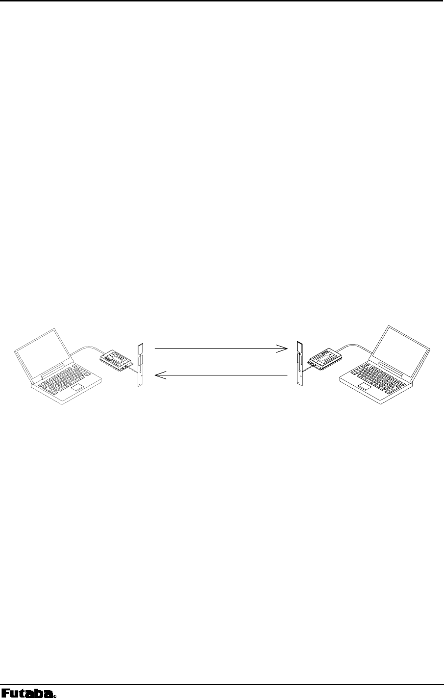
Page 48 FRH-SD07TU/TB Manual
Rev. 020510-01
4.2.1.3 Communication (1:1 – Mode 3)
In packet transmission mode, data is transmitted by using the transmit commands (TXT,
TBN, etc.).
1. Master Station transmits a message to Slave Station.
command:
@TXT001HELLO CR/LF
2. Master Station returns the response to the terminal equipment.
response: P1
CR/LF
3. Slave Station receives the message, verifies that the message is addressed to it,
outputs the data to its terminal equipment, and returns an ACK packet to Master
Station.
output: RXT000HELLO
CR/LF
4. Master station receives the ACK and responds to the terminal equipment
“Successive Completion” response.
response: P0
CR/LF
Master Station Slave Station
Figure 4–2: Communication Configuration (1:1 – Mode 3)
Data Transmission
ACK
p
acket

Page 49
Futaba Corporation Rev. 020510-01
4.2.2 Communication Example (1:n – Mode 3)
This section describes an example of 1:n communication in packet transmission mode
(Mode 3). In multiple station topology, each station’s memory register setting must be
unique local station address (REG00). In this mode, all transmissions are made using the
transmit commands (TXT, TBN, etc.). The following example assumes that there are one
master and three slave stations.
4.2.2.1 Terminal Software Setup (1:n – Mode 3)
Set the terminal software as follows: (refer your software instructions for setup details)
bit rate: 9600 bps
data length: 8 bits
stop bits: 1 bit
parity bit: none
flow control: none
local echo: yes
terminator: carriage return + line feed
This setting corresponds to the factory default state of the modem. When REG20 and
REG21 are changed, change the terminal software setup accordingly.
Check for proper communication between the terminal equipment and the modem after
setting these parameters. To do this, turn the modem power on and with the communication
software running, enter “@ARG CR/LF” at the terminal prompt. If functioning properly, the
modem should return the value of all 28 memory registers to the terminal screen.
4.2.2.2 Modem Setup (1:n – Mode 3)
1. Set the local station addresses (REG00) as follows:
Master Station 000
Slave Station 1 001
Slave Station 2 002
Slave Station 3 003
2. Set Bit 0 of REG18 to “1” (to perform “destination address checking”)
3. Leave all other memory registers at the factory default settings.
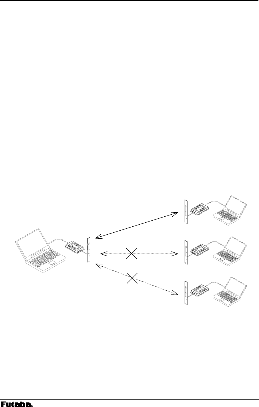
Page 50 FRH-SD07TU/TB Manual
Rev. 020510-01
4.2.2.3 Communication (1:n – Mode 3)
In packet transmission mode, data is transmitted by using the transmit commands (TXT,
TBN, etc.).
1. Master Station transmits a message to Slave Station 1.
command:
@TXT001HELLO CR/LF
2. Slave Station 1 receives the message, verifies that the message is addressed to it,
outputs the data to its terminal equipment, and returns an ACK packet to Master
Station.
output: RXT000HELLO
CR/LF
3. Slave Stations 2 and 3 also receive the message, but since the destination address
does not match theirs, they discard the data and do not output it to their respective
terminal equipments.
4. Master Station receives the ACK from Slave Station 1.
Figure 4–3: Communication Configuration (1:n – Mode 3)
Slave 1
Slave 2
Slave 3
Master

Page 51
Futaba Corporation Rev. 020510-01
4.2.3 Communication Example (n:m – Mode 3)
RS485 mode is suitable for assigning several master modems in a wide area using RS485
multi-drop communication topology. In this example; 3 master modems and 2 slave modem
case is explained. The slave modem can keep on radio communication while moving, by
automatically changing the communication to master modems (roaming function).
4.2.3.1 Terminal Software Setup
Example:
Set the terminal software as follows: (refer your software instructions for setup details)
bit rate: 9600 bps
data length: 8 bits
stop bit: 1 bit
parity bit: none
flow control: none
local echo: yes
terminator: carriage return + line feed
This setting corresponds to the factory default state of the modem. When REG20 and
REG21 are changed, change the terminal software setup accordingly.
Check for proper communication between the terminal equipment and the modem after
setting these parameters. To do this, turn the modem power on and with the communication
software running, enter “@ARG CR/LF” at the terminal prompt. If functioning properly, the
modem should return the value of all 28 memory registers to the terminal screen.
4.2.3.2 Modem Setup
Example:
(1) Master (Base) Station Setup
1. Pull down Pin 12 (/RS485ENB) at about 10 k ohm register. (RS485 mode) At this
time, do NOT connect this pin DIRECTLY to GND.
2. Set the local station address of the modem as follows. (REG00 or REG01)
REG00 REG01
Master modem 1 001 240
Master modem 2 002 240
Master modem 3 002 240
3. Set REG18:bit 0 to 1. (to perform Destination Address Checking)
4. Allocate the frequency No. 0, 8, 16 in the fixed frequency mode (REG06), which
corresponds to Group 0 of Grouping Method F.
Master modem 1 E0H (Frequency No. 0, fixed)

Page 52 FRH-SD07TU/TB Manual
Rev. 020510-01
Master modem 2 E8H (Frequency No. 8, fixed)
Master modem 3 EFH (Frequency No. 16, fixed)
5. Set REG19:bit 1 to 1 (to perform Regularly transmit radio beacon without
transmission request).
6. Use the default value for other memory registers.
(2) Slave (Mobile) Station Setup
1. Since the slave modem is in the RS232C mode, it is not necessary to pull down Pin
12 of the serial communication connector
2. Set the local station address (REG00) of the modem as follows.
Slave modem 1 101
Slave modem 2 102
3. Set REG18:bit 0 to 1 (to perform Destination Address Checking).
4. Set the frequency group (REG06) to A0H (group 0 of Grouping Method F) to
make it correspond to the frequency of the maser modems.
5. Set REG19:bit 2 to 1 (to be Wait-to-receive mode by fixing frequency while the
correlation detection is made).
6. Use the default value for other memory registers.
4.2.3.3 Communication
Example:
1. If there is Slave Station 2 near Master Station 1, Slave Station 2 receives the radio
beacon of Master Station 1 and its frequency is fixed at No. 0.
2. @TXT240HELLO CR/LF : Issue the transmit command to Slave Station 2. Be
noted that the address is 240 (global addressed destination).
3. Since slave stations transmit data to master stations as the global addressed
destination, slave station need not aware which master station responds. Only the
master station who has the same frequency receives and responds. (In this case,
Master Station 1.)
4. RXT102240HELLO CR/LF : Master Station 1 outputs data to PC.
5. When Slave Station 2 enters into the area of Master Station 2, it receives the radio
beacon from Master Station 2 and its frequency is fixed at No.8.
6. @TXT102240MAIL CR/LF : Issue the transmit command to master stations. Be
noted that the sender address is 240, global addressing.
7. Global addressed master stations are transmit data to slave station. Using the global
addressing, that is, three master stations transmit the same data at the same time.
Accordingly, it is not necessary to aware where slave station is. Only the slave station
who has the same address receives the data. (In this case, Slave Station 2.)
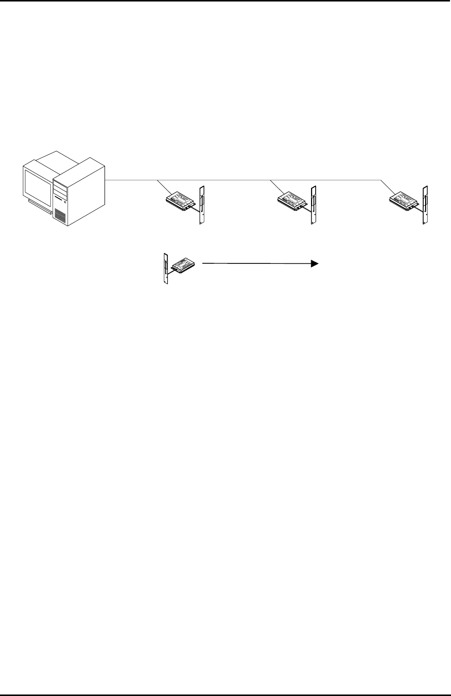
Page 53
Futaba Corporation Rev. 020510-01
8. RXT240MAIL CR/LF : Slave Station 2 outputs the received data to the
terminal equipment.
As described above, the slave station can communicate in wide area without considering
where it is.
Fig. 4–8: n:m Communication (Roaming)
Master 1
Freq.No. 0 Master 2
Fre
q
.No. 8
Master 3
Fre
q
.No.16
Slave 2
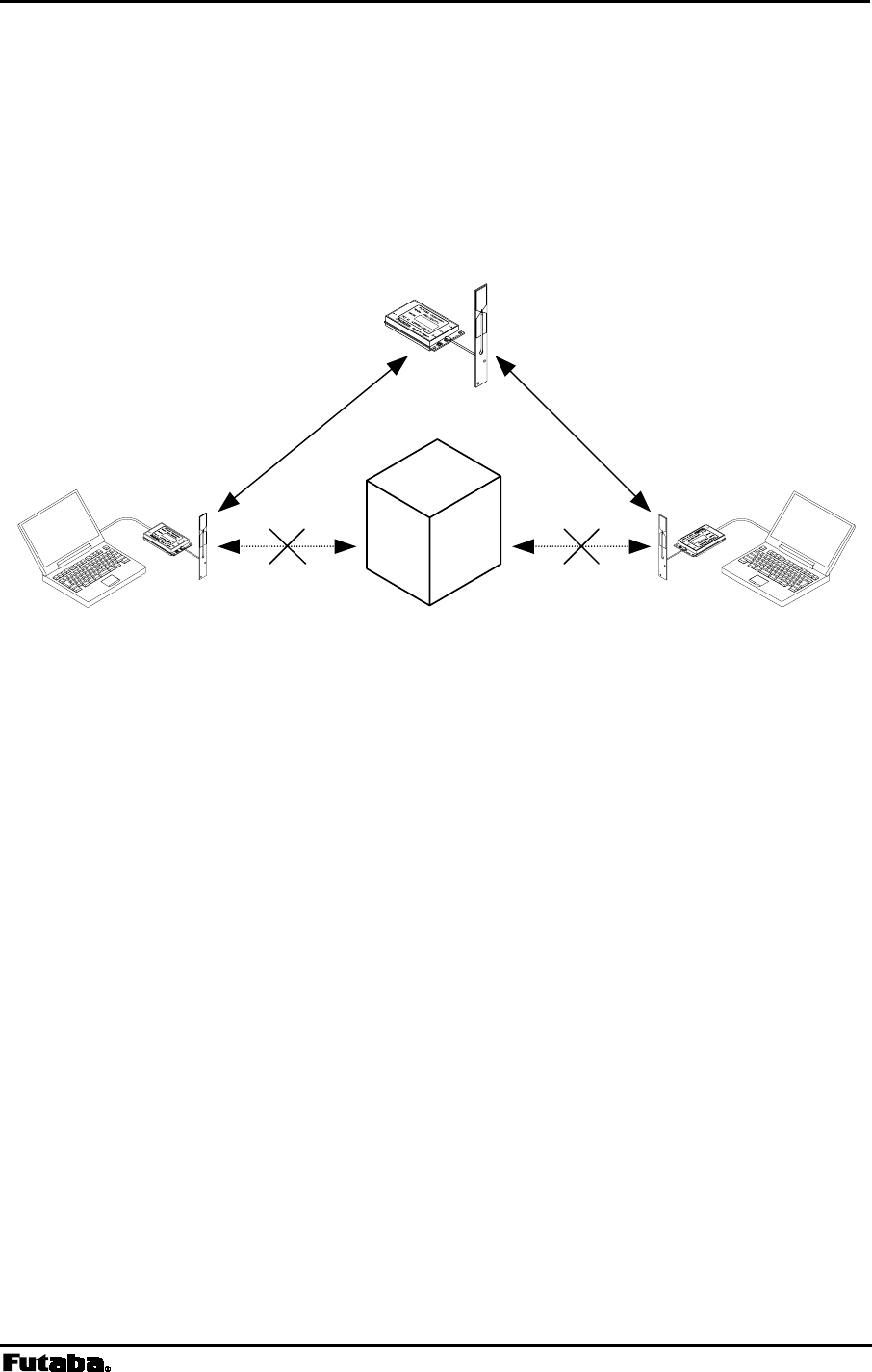
Page 54 FRH-SD07TU/TB Manual
Rev. 020510-01
4.2.4 Repeater Example (Mode 4)
The FRH-SD07TU/TB can be used as a repeater to extend the wireless communication
range or eliminate null zones caused by obstructions. The following example uses one
repeater and two modems.
Figure 3–10: Repeater
4.2.4.1 Communication Through a Repeater (Mode 4)
• When two modems cannot reliably communicate because of excessive distance or
obstructions, a third modem can act as a repeater. The repeater is placed in a position
where it can communicate with both modems.
• Although PC or terminal equipment is used to configure the modem as a repeater, it is
not necessary to connect PC or terminal to the repeater once it is configured and
functioning normally. The repeater can operate in a stand-alone mode.
• Multiple repeaters can be used in a network, but stations can only communicate to
other stations through one repeater. Communication through two or more repeaters is
not possible.
• When communicating through a repeater , the repeater transmit commands (TXR,
TBR, and RTY) must be used.
• When using a repeater , all modems in the radio-network must be set to the same fixed
frequency.
• Communication through the repeater approximately doubles the communication time
delay.
Modem 1 Modem 2
Repeater
Obstacle

Page 55
Futaba Corporation Rev. 020510-01
4.2.4.2 Terminal Software Setup (Mode 4)
Set the terminal software as follows: (refer your software instructions for setup details)
bit rate: 9600 bps
data length: 8 bits
stop bits: 1 bit
parity bit: none
flow control: none
local echo: yes
terminator: carriage return + line feed
This setting corresponds to the factory default state of the modem. When REG20 and
REG21 are changed, change the terminal software setup accordingly.
Check for proper communication between the terminal equipment and the modem after
setting these parameters. To do this, turn the modem power on and with the communication
software running, enter “@ARG CR/LF” at the terminal prompt. If functioning properly, the
modem should return the value of all 28 memory registers to the terminal screen.
4.2.4.3 Modem Setup (Mode 4)
1. Set the local station address of the modem (REG00) as follows.
Wireless Modem 1: 001
Wireless Modem 2: 002
2. Set REG06 (Frequency Grouping) at the fixed Frequency No. 0 of Grouping
Method H.
3. Set REG18:bit 0 to 1 (to perform Destination Address Checking).
4. Set REG19:bit 0 to 0 (to use as a modem).
5. Use the default value for other memory registers.
4.2.4.4 Repeater Setup (Mode 4)
1. Set REG00 (the local address of the repeater) to 000.
2. Set REG06 at the fixed frequency No. 0 of Grouping Method H.
3. Set REG18:bit 0 to 1 (to perform Destination Address Checking).
4. Set REG19:bit 0 to 1 (to use as a repeater).
5. Use the default value for other memory registers.

Page 56 FRH-SD07TU/TB Manual
Rev. 020510-01
4.2.4.5 Communication (Mode 4)
To communicate using the repeater , use the repeater transmit commands. The below
describes the operation of each modem when a simple message is sent.
1. Message is sent from Modem 1 (001) to Modem 2 (002) through Repeater (000).
command:
@TXR000002HELLO CR/LF
2. Modem 1 transmits the message to the repeater. Repeater receives the message,
verifies that the message is for its address, then retransmits the unaltered message to
Modem 2.
3. Modem 2 receives the message and verifies that the message is addressed to itself,
then it outputs the message to its terminal equipment and returns an ACK packet
through the repeater .
output: RXR000001HELLO
CR/LF
4. Repeater receives the ACK, verifies its address then retransmits the ACK without
changing it to Modem 1.
5. Modem 1 receives the ACK and output the response to the terminal equipment.
output: P0
CR/LF
Do not use the modem set as the repeater for other commands than
listed below to avoid operation error.
ARG: to reference memory registers
INI: to initialize all memory registers
REG: to reference and set memory registers
RST: to reset
VER: to read out a version
CAUTION
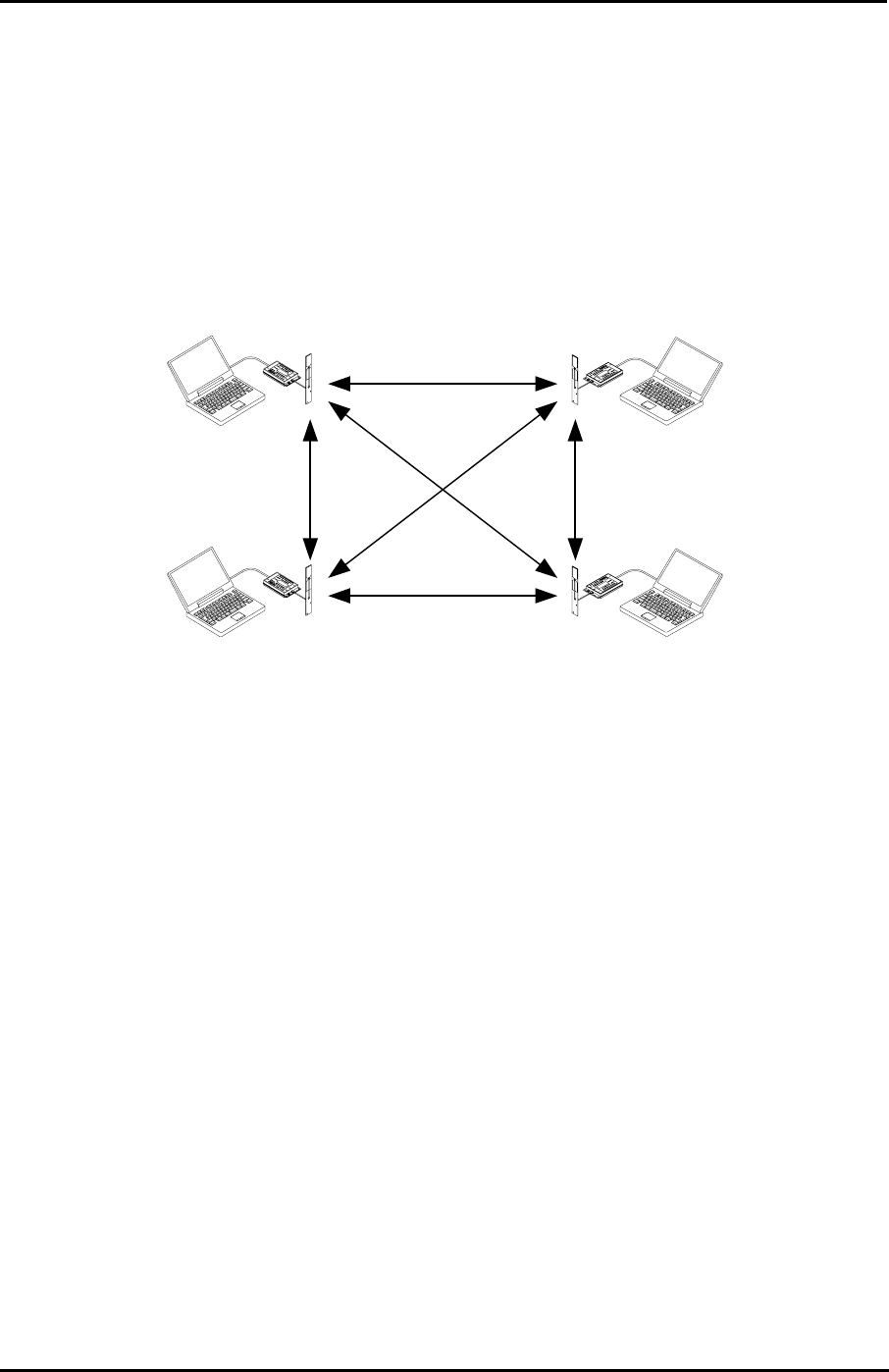
Page 57
Futaba Corporation Rev. 020510-01
4.2.5 Other Communication Configurations
Many other communication topology can be configured with the FRH-SD07TU/TB modem.
The following section briefly describes a few of them.
4.2.5.1 n:n Communication
The modem can execute the N:N communication where all modems are in the equality
relation.
Figure 3–12: n:n Communication
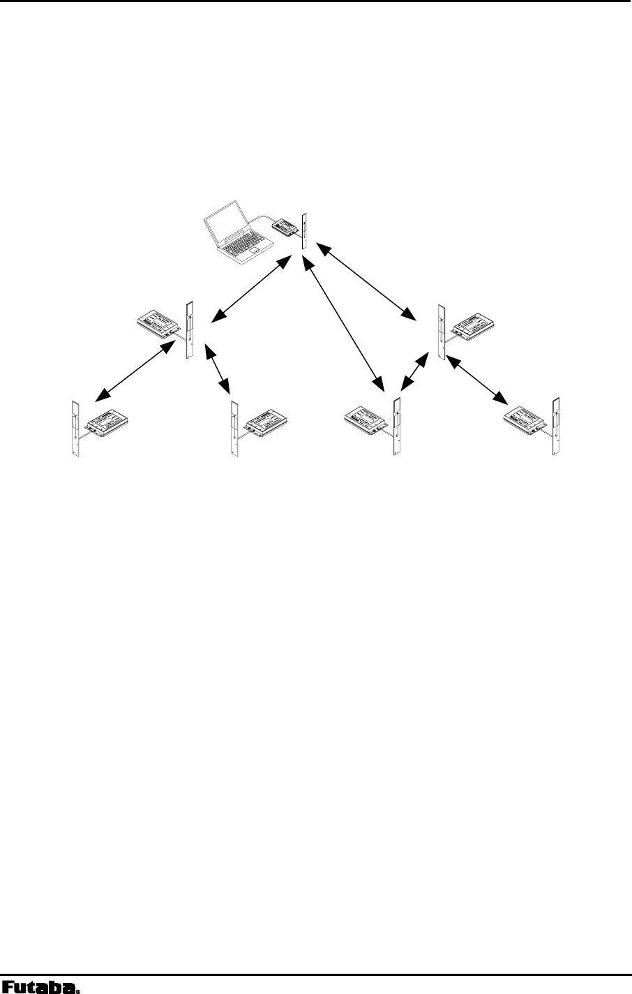
Page 58 FRH-SD07TU/TB Manual
Rev. 020510-01
4.2.5.2 Packet Transmission Mode 1:n:m Connection
One master modem can transmit data to multiple groups of slaves by using multiple
repeaters. The master and slaves can also be communicated directly to each other, without
passing the repeater .
Figure 3–13: Packet Transmission Mode 1:n:m
Repeater 2
Repeater 1
Slave 1 Slave 2 Slave 3 Slave 4
Master

Page 59
Futaba Corporation Rev. 020510-01
5
SECTION
5 MEMORY REGISTER DESCRIPTION
CONTENTS
5 MEMORY REGISTER DESCRIPTION ..............................................................59
5.1 MEMORY REGISTER DESCRIPTION ............................................................................................ 60
REG00: LOCAL STATION ADDRESS [DEFAULT VALUE: 00H].............................................................. 61
REG01: LOCAL STATION GLOBAL ADDRESS [DEFAULT VALUE: F0H]................................................. 61
REG02: DESTINATION ADDRESS [DEFAULT VALUE: 00H] ................................................................. 61
REG03: SPECIAL SETTING [DEFAULT VALUE: F0H].......................................................................... 61
REG04: ID CODE 1 [DEFAULT VALUE: 00H] .................................................................................... 61
REG05: ID CODE 2 [DEFAULT VALUE: 00H] .................................................................................... 62
REG06: FREQUENCY GROUP [DEFAULT VALUE: A0H]...................................................................... 62
REG07: PACKET INTERVAL [DEFAULT VALUE: 05H].......................................................................... 63
REG08: RESERVED [DEFAULT VALUE: 11H] .................................................................................... 63
REG09: RESERVED [DEFAULT VALUE: 13H] .................................................................................... 63
REG10: COMMAND HEADER [DEFAULT VALUE: 40H]........................................................................ 63
REG11: RETRANSMISSION COUNT [DEFAULT VALUE: 32H]............................................................... 64
REG12: ROAMING THRESHOLD [DEFAULT VALUE: B4H]................................................................... 64
REG13: RESERVED [DEFAULT VALUE: 1EH].................................................................................... 64
REG14: RECEIVE DATA OUTPUT INTERVAL [DEFAULT VALUE: 00H].................................................. 64
REG15: COMMAND RECOGNITION INTERVAL [DEFAULT VALUE: 00H]................................................64
REG16: COMMAND INPUT TIMEOUT [DEFAULT VALUE: 32H]............................................................. 65
REG17: RESERVED [DEFAULT VALUE: 32H] .................................................................................... 65
REG18: COMMUNICATION SETTING 1 [DEFAULT VALUE: 8CH].......................................................... 66
REG19: COMMUNICATION SETTING 2 [DEFAULT VALUE: 00H] .......................................................... 67
REG20: RS-232C SETTING 1 [DEFAULT VALUE: 05H]..................................................................... 69
REG21: RS-232C SETTING 2 [DEFAULT VALUE: 09H]..................................................................... 70
REG22: RS-232C SETTING 3 [DEFAULT VALUE: 00H]..................................................................... 72
REG23: MISCELLANEOUS SETTINGS [DEFAULT VALUE: 00H]............................................................ 74
REG24: SPECIAL MODE SETTINGS [DEFAULT VALUE: C0H].............................................................. 76
REG25: ULTRA MODE SETTINGS [DEFAULT VALUE: 40H]............................................................... 77
REG26: RESERVED [DEFAULT VALUE: 00H] .................................................................................... 77
REG27: FREQUENCY BAND SETTINGS [DEFAULT VALUE: 01H] ......................................................... 78

Page 60 FRH-SD07TU/TB Manual
Rev. 020510-01
5.1 Memory Register Description
The FRH-SD07TU/TB modem contains 28 memory registers which are used to control and
store communication parameters and operation mode settings. After rewriting new register
settings, the power must be cycled, a hardware reset asserted, or a software RST command
is issued to validate the new settings.
Functions of some memory registers vary depending on the operation mode. This chapter
describes the communication modes 3 and 4. For communication modes 5 and 6, refer to
p.117 ADVANCED APPLICATION.
The following table briefly lists each register, register function and default value:
Register Function Default Value Meaning
REG00 Local Station Address 00 H address 0
REG01 Local Station Global Address F0 H address 240
REG02 Destination Address 00 H address 0
REG03 Special Setting F0 H F0H
REG04 ID Code 1 00 H address 0
REG05 ID Code 2 00 H address 0
REG06 Frequency Group A0 H see text
REG07 Packet Interval 05 H 5 ms
REG08 Reserved 11 H 11H
REG09 Reserved 13 H 13H
REG10 Command Header 40 H character @
REG11 Retransmission Count 32 H 50 count
REG12 Roaming Threshold B4 H -180dBm
REG13 Reserved 1E H 1EH
REG14 Receive Data Output Interval 00 H 0 ms
REG15 Command Recognition Interval 00 H 0 s
REG16 Command Input Timeout 32 H 32H
REG17 Reserved 32 H 32H
REG18 Communication Setting 1 8C H see text
REG19 Communication Setting 2 00 H see text
REG20 Serial Interface Setting 1 05 H see text
REG21 Serial Interface Setting 2 09 H see text
REG22 Serial Interface Setting 3 00 H see text
REG23 Serial Interface Setting 4 00 H see text
REG24 Miscellaneous Settings C0 H see text
REG25 ULTRA Mode Settings 40 H see text
REG26 Reserved 00 H
REG27 Frequency Band Settings 00 H see text
Table 5–1: Memory Registers
Suffix ‘H’ of each default value denotes HEX radix expression in the value.

Page 61
Futaba Corporation Rev. 020510-01
REG00: Local Station Address [default value: 00H]
• Sets the local station address. Valid values are 000 to 239. (240 addresses)
• This value is inserted in the “source address” field in the transmitted packet header.
• If the address check function is enabled (REG18) in the receiving modem, the
modem can receive the packet which header contains destination address information
identical to REG00.
• In the RS485 mode, this register is used as 485 mode local station address.
REG01: Local Station Global Address (RS485) [default value: F0H]
• Sets the local station global address of the modem. Valid values are 240 to 254. (15
addresses)
• When plural modems are connected by RS485 multi-dropping topology, commands can
be issued to multiple modems simultaneously by setting all connected modems to the
same global address. This is the global addressing.
• This global addressing allows to handle multiple multi-dropped modems as if they
were one modem.
REG02: Destination Address [default value: 00H]
• This address is used in the headerless packet transmission mode (communication
modes 5). For details, refer to p.118 HEADERLESS PACKET TRANSMISSION MODE.
• Use the default value for the transmission mode 3 or 4.
REG03: Special Setting [default value: F0H]
• Sets special operation modes such as headerless packet transmission mode or
direct transmission mode. Refer to p.117 ADVANCED APPLICATION.
• Use the default value for the transmission mode 3 or 4.
REG04: ID Code 1 [default value: 00H]
• Used with ID code 2 (REG05), set the ID code. Valid values are 000 to 255. Together
with ID code 2, up to 61,440 ID codes can be set.
• The ID code identifies the group of the modems works in the same group. The ID code
is used to prevent erroneous connection with other systems and for communication
security.

Page 62 FRH-SD07TU/TB Manual
Rev. 020510-01
• Before transmission, radio data packets are scrambled using a pseudo-random data
sequence generated with this ID code as the seed. During reception, the original data is
restored by de-scrambling it with the pseudo-random data sequence. The modems with
different ID codes cannot communicate with each other.
REG05: ID Code 2 [default value: 00H]
• Used with ID code 1 (REG04), set the ID code. Valid values are 000 to 239. Together
with ID code 1, up to 61,440 ID codes can be set.
• Do not set the value 240 and above. If excess value is set, the modem ignores the
REG04 and REG05 value and assigns REG04 to 255 and REG05 to 239.
• In case plural modems are used as a single system, always set the same ID code for all
modems and repeaters.
REG06: Frequency Group [default value: A0H]
• Refer to p.35 FREQUENCY GROUPING in Section 3, for a detailed description of the
frequency operation modes.
Bits 7 – 5: Grouping of frequency
Grouping Setting Bit 7 Bit 6 Bit 5
A 24 freq. × 1 group 0 0 0
B 12 freq. × 2 group 0 0 1
C 8 freq. × 3 group 0 1 0
D 6 freq. × 4 group 0 1 1
E 4 freq. × 6 group 1 0 0
F 3 freq. × 8 group 1 0 1
G 2 freq. ×12 group 1 1 0
H 1 freq. ×24 group 1 1 1
Table 5–2: Grouping of Frequency
• Set the grouping method for the 24 available frequencies. The number of available
frequencies per group is allocated to perform multi-access in the frequencies of group.
• The multi-access function is performed within a frequency group.
• When more frequencies per group are made available for multi-access function, the
system will gain an advantage in overcoming interference and fading, but average time
required to establish a connection will increase because more frequencies are scanned.

Page 63
Futaba Corporation Rev. 020510-01
Bits 4 – 0: Group Number
Group No. Bit 4 Bit 3 Bit 2 Bit 1 Bit 0
0 0 0 0 0 0
1 0 0 0 0 1
2 0 0 0 1 0
3 0 0 0 1 1
4 0 0 1 0 0
: : : : : :
: : : : : :
19 1 0 0 1 1
20 1 0 1 0 0
21 1 0 1 0 1
22 1 0 1 1 0
23 1 0 1 1 1
Table 5–3: Frequency Group Settings
• The frequency group number is set. Valid group numbers for setting vary
depending on the frequency grouping method.
REG07: RS485 Packet Interval [default value: 05H]
• In the packet transmission mode with the RS485 mode is used, sets the interval
between response and/or received data which output from the modem to RS485 line.
• Be able to set 0 to 254 ms at increment of 1 ms. 255ms is not allowed. The default
value is 5 ms.
• Set this interval to a larger value than the receiving interval set by REG14.
• Suitable setting of this interval avoids the data collision possibility of RS485 line.
For details, refer to p.31 COLLISION AVOIDANCE IN RS485 INTERFACE.
REG08: Reserved [default value: 11H]
• The FRH-SD07TU/TB does not use this register. Keep the default value as it is.
REG09: Reserved [default value: 13H]
• The FRH-SD07TU/TB does not use this register. Keep the default value as it is.
REG10: Command Header [default value: 40H]
• Sets the character that identifies the start of a command.
• The default is character “@” (40H).

Page 64 FRH-SD07TU/TB Manual
Rev. 020510-01
• When this character is input from the terminal equipment after no character is received
for the command recognition interval (REG15) or longer, subsequent input
character is recognized as a command for the modem.
REG11: Retransmission Count [default value: 32H]
• Sets the maximum number of packet retransmission attempts. Valid values are 000
to 254. 255 is not allowed.
• When retransmission exceeds the retransmission count (retransmission count plus
one for broadcast transmission), the modem outputs an error response to the
terminal equipment.
REG12: Roaming Threshold [default value: B4H]
• At the time to set the frequency roaming (REG19:bit 2 is 1), set the receiving
strength threshold of the radio beacon which starts scanning frequency.
• Set the value of the desired radio beacon strength threshold represented in dBm
excluding the minus sign, e.g., set to “80” to search the next master station when the
radio beacon strength becomes below –80 dBm.
REG13: Reserved [default value: 1EH]
• The FRH-SD07TU/TB does not use this register. Keep the default value as it is.
REG14: Receive Data Output Interval [default value: 00H]
• Sets the minimum time interval between characters (time from the stop bit of one
character to the start bit of the next character) when outputting data from the modem to
the terminal equipment.
• Valid values are 000 to 255, representing milliseconds in 1 ms increments.
• Since the modem transmit data to other end modem in packet form, minimal interval
between the character output to the terminal equipment does not guaranteed. Characters
are continuously sent to the terminal equipment until the modem’s buffer becomes
empty. When the data cannot be received by the terminal equipment, set this interval
longer.
REG15: Command Recognition Interval [default value: 00H]
• When a message data contains a command header character (in case of binary data or
data in two-byte Chinese characters), data following the command header character
will be interpreted as a command, the message does not transmit properly.

Page 65
Futaba Corporation Rev. 020510-01
• Sets the necessary vacant duration time interval to discriminate between ordinary data
character and a command header character. Input a command after a longer interval
than time interval setting.
• Valid values are 0.1 to 25.4 sec., representing tenths of seconds in 0.1 second
increments. (Set an integer value equal to ten times the number of seconds desired.)
• When set to 000, the command header is recognized at any time, and when set to 255,
all command header character are ignored.
REG16: Command Input Timeout [default value: 32H]
• Sets the character input timeout interval for command input. It is used as the
timeout between the command header and the character following it and between
each character of the command.
• At the timeout, the modem operation transits from command-input-wait-state to
ordinary-data-wait-state.
• Valid values are 000 to 255, representing tenths of seconds in 0.1 second increments.
(Set an integer value equal to ten times the number of seconds desired.)
• A setting of 000 disables this timeout function.
REG17: Reserved [default value: 32H]
• The FRH-SD07TU/TB does not use this register. Keep the default value as it is.
Page 66 FRH-SD07TU/TB Manual
Rev. 020510-01
REG18: Communication Setting 1 [default value: 8CH]
Bits 7 – 2: Reserved
• The FRH-SD07TU/TB does not use this register. Keep the default value as it is.
Bit 1: Source address check
0 Inhibit source address checking (default value)
1 Activate source address checking
Table 5–4: Source Address Check Settings
• When the source address checking is active and the source address in the received
packet header does not match the destination address setting (REG02), the data is
discarded (data cannot be received).
Bit 0: Destination address check
0 Inhibit destination address checking on receipt (default)
1 Activate destination address checking on receipt
Table 5–5: Destination address check
• When the destination address checking is active and the destination address in the
received packet header does not match the received modem’s local station address
(REG00), the data is discarded (data cannot be received).
Page 67
Futaba Corporation Rev. 020510-01
REG19: Communication Setting 2 [default value: 00H]
Bit 7: Reserved
• The FRH-SD07TU/TB does not use this register. Keep the default value as it is.
Bit 6: Diversity Reception
0 Disable diversity reception (default value)
1 Enable diversity reception
Table 5–6: Diversity Reception Settings
• Enable/disable diversity reception.
• To enable diversity reception, set this bit to 1 and connect an antenna to Antenna
Terminal B.
• Enabling diversity reception with only one antenna connected may degrade the
reception performance.
Bit 5: Broadcast Transmission Reception
0 Enable broadcast transmission reception (default value)
1 Disable broadcast transmission reception
Table 5–7: Broadcast Reception Settings
• Enable/disable reception of broadcast transmission in packet transmission mode
(Mode 3 and 5).
Bit 4: Antenna selection
0 Receiving antenna is fixed to A (default value)
1 Receiving antenna is fixed to B
Table 5–8: Antenna Selection
• At the non-diversity reception, decide the antenna terminal for the receiving
antenna fixing.
• Selection of 1 fixes the receiving antenna to the terminal B. When the high gain
antenna connecting to the terminal B is used for reception, this setting would achieve
better performance than the diversity reception in some case.
Page 68 FRH-SD07TU/TB Manual
Rev. 020510-01
Bit 3: Extended reception
0 Disable extended reception (default value)
1 Enable extended reception
Table 5–9: Extended reception
• Contention type communication in packet transmission mode (including the
headerless packet transmission mode) may cause repetitive retransmission when
two modems are in transmission state in identical timing. This results in the decrease of
response rate or the transmission failure.
• This extend reception function solves such problems as above. The data packet
received during carrier sensing are received first by interrupting the on-going
transmission operation. For further detail, refer to p.24 EXTEND RECEIVING.
Bit 2: Receiving frequency change
0 Regularly change frequency within a group while waiting (default value)
1 Fix the frequency to wait while data can be regularly received.
Table 5–10: Receiving frequency change
• Set the changing method of receiving frequency in packet transmission mode. Sets
roaming function with combining bit 1.
Bit 1: Beacon transmission
0 No transmission until transmission command is requested (default)
1 Enable regular beacon transmission.
Table 5–11: Beacon Transmission
• Enable or disenable beacon transmission in packet transmission mode.
• Set roaming function with combining bit 2.
Bit 0: Operation Mode
0 Operates in normal modem mode
1 Operates as a repeater
Table 5–12: Operation Mode Settings
• Sets the modem to operate either as a normal modem or as a repeater. Effective only
in packet transmission mode (Mode 3, 4 and 5).
Page 69
Futaba Corporation Rev. 020510-01
REG20: RS-232C Setting 1 [default value: 05H]
Bit 7: Data Length
0 8 bit data bytes (default value)
1 7 bit data bytes
Table 5–13: Data Length Settings
Bit 6: Parity Bit
0 No parity bit (default value)
1 Parity bit
Table 5–14: Parity Settings
Bit 5: Even/Odd Parity
0 Even parity (default value)
1 Odd parity
Table 5–15: Odd/Even Parity Settings
• Invalid when bit 6 is set to 0, without parity.
Bit 4: Stop Bit
0 1 stop bit (default value)
1 2 stop bits
Table 5–16: Stop Bit Settings

Page 70 FRH-SD07TU/TB Manual
Rev. 020510-01
Bits 3 – 0: Baud rate setting
Bit 3 Bit 2 Bit 1 Bit 0 Setting
0 0 0 0 300 bps
0 0 0 1 600 bps
0 0 1 0 1200 bps
0 0 1 1 2400 bps
0 1 0 0 4800 bps
0 1 0 1 9600 bps (default)
0 1 1 0 19200 bps
0 1 1 1 38400 bps
1 0 0 0 50000 bps
1 0 0 1 62500 bps
1 0 1 0 83333 bps
1 0 1 1 100000 bps
1 1 0 0 57600 bps
1 1 0 1 115200 bps
1 1 1 0 Reserved
1 1 1 1 Reserved
Table 5–17: Baud Rate
• Because of the limitation of internal processing speed in the processor, character output
throughput is limited up to 60 us interval. When baud rate 83333 bps and faster is
selected, the throughput which expected from its baud rate can not be obtained.

Page 71
Futaba Corporation Rev. 020510-01
REG21: RS-232C Setting 2 [default value: 09H]
Bits 7 – 2: Reserved
• The FRH-SD07TU/TB does not use this register. Keep the default value as it is.
Bit 1: Flow Control
0 No flow control (default value)
1 Hardware flow control
Table 5–18 Software/Hardware Flow Control Settings
• Selects the flow control method. This setting must match the connected terminal
equipment’s setting.
• Hardware flow control uses the two control lines RTS and CTS. When using
hardware flow control, be sure that RTS and CTS lines are properly wired.
• When using with the RS485 interface, be sure to set to 0.
Bit 0: Reserved
• The FRH-SD07TU/TB does not use this register. Keep the default value as it is.
Page 72 FRH-SD07TU/TB Manual
Rev. 020510-01
REG22: RS-232C Setting 3 [default value: 00H]
Bit 7: Enable and Disable Reception
0 Enable reception at the initial state (default value)
1 Disable reception at the initial state
Table 5–19: Enable/Disable Reception
• Select enable or disable reception at the initial state in the packet transmission mode.
• The initial state is in reception enable. Depending on an usage of the modem, the
initial state of the modem may be better in the reception disable state. In such a case,
use this setting.
• Issue the REN command to enable reception.
Bit 6: Reserved
• The FRH-SD07TU/TB does not use this register. Keep the default value as it is.
Bits 5 – 4: DCD (Data Carrier Detect)
Bit 5 Bit 4 Setting
0 0 Ignore DCD input; DCD output always ON (default value)
0 1 Reserved
1 0 Remote modem’s DCD (IN) is transferred to local modem DCD (OUT).
(DCD Output = OFF at reset state)
1 1 Remote modem’s DCD (IN) is transferred to local modem DCD (OUT)
(DCD Output = ON at reset state)
Table 5–20: DCD Settings
• When connecting to the telephone line modem, set the FRH-SD07TU/TB modem to
transfer the DCD input of the remote modem to the DCD output of the local modem.
• Operation on Direct Transmission Mode differs. Please refer to p.127 DIRECT
TRANSMISSION MODE.
Page 73
Futaba Corporation Rev. 020510-01
Bits 3 – 2: DTR/DSR
Bit 3 Bit 2 Setting
0 0 Ignore DTR input; DSR output always ON (default value)
0 1 Reserved
1 0 Remote modem DTR is transferred on local modem CTS (CTS = OFF at
reset state)
1 1 Remote DTR is transferred on local modem CTS (CTS = ON at reset
state)
Table 5–21: DTR/DSR Control Settings
• When connecting to the telephone line modem, set the FRH-SD07TU/TB modem to
allow to transmit the DTR input of the remote modem to the DSR output of the local
modem.
• Operation on Direct Transmission Mode differs. Please refer to p.127 DIRECT
TRANSMISSION MODE.
Bits 0 – 1: RTS/CTS
Bit 1 Bit 0 Settings
0 0 Ignore RTS input; CTS output always ON
0 1 Reserved
1 0 Remote modem RTS is output on local modem CTS (CTS = OFF at reset)
1 1 Remote modem RTS is output on local modem CTS (CTS = ON at reset)
Table 5–22: RTS/CTS Control Settings
• When hardware flow control is enabled (REG21), this setting is ignored.
• Operation on Direct Transmission Mode differs. Please refer to p.127 DIRECT
TRANSMISSION MODE.

Page 74 FRH-SD07TU/TB Manual
Rev. 020510-01
REG23: Miscellaneous Settings [default value: 00H]
Bit 7 – 5: reserved
• The FRH-SD07TU/TB does not use this register. Keep the default value as it is.
Bit 4 : CR/LF addition/deletion
• Especially used for the headerless packet transmission mode only. Refer to p.124
MEMORY REGISTER SETTING, IN HEADERLESS PACKET TRANSMISSION MODE.
Bit 3: reserved
• The FRH-SD07TU/TB does not use this register. Keep the default value as it is.
Bit 2: RS485 collision avoidance regular interval output
0 No C/R code output for collision avoidance (default value)
1 Regularly output C/R code for collision avoidance
Table 5–23: C/R Code Regular Interval Output
• Sets whether the collision avoidance function is used or not, together with bit 1.
• When this bit is set to 1, responses or data will be output to RS485 line if there are
such responses or data exist in the buffer at the timeout of the RS485 Packet
Interval (REG07). If there are no such responses or data exist in the buffer, the C/R
code (0Dh) is compulsorily output.
• The effective use of this function helps to shift the output timing of multi-dropped
modems on RS485 line. Eventually it avoids the data collision on the RS485 line.
• To use this function, set REG23:bit 1 of all RS485 multi-dropped modems to 1. And
set all the RS485 Packet Interval (REG07) to different values more than 1.5 bytes
each. Further set this bit of the modem, the RS485 Packet Interval is set to the
longest, to 1.

Page 75
Futaba Corporation Rev. 020510-01
Bit 1: RS485 collision avoidance
0 Invalid collision avoidance function (default value)
1 Use collision avoidance function
Table 5–24: Collision Avoidance Function
• Sets to decide whether to use the collision avoidance function or not, together with
bit 2.
• When modem tried to output a response or the received data, the modem outputs only
if RS485 line is available at the timeout of RS485 Packets Interval (REG07). When
RS485 line is not available at the timeout, the modem waits for a line becomes
available and starts re-measurement of its packet interval.
• Set to 1 makes it unable to output neither response nor the received data, unless other
modem(s) outputs any data to the RS485 line and interval time measuring becomes
effect.
• Bit 2 is used for the purpose of resolving this problem.
Bit 0: Global addressing command response
0 No P0 response to global addressing command (default value)
1 Respond P0 response to global addressing command
Table 5–25: Global addressing command response
• Set to decide whether to return “P0” response (including “P1” for the transmit
command) to the terminal equipment for the global addressing command
(commands for Addresses 240 to 254).
• When the global addressing command is issued to plural modems, which are multi-
dropped and have the same global address on RS485 line, there is a possibility
causing data collision on the RS485 line. Unless the RS485 Packet Interval is
properly set. This is because all modems return the “P0” (or P1) response to the
terminal equipment simultaneously on default memory setting. Such potential
problem can be avoided by limiting the modem to output the response to the global
addressing command is only one.
Page 76 FRH-SD07TU/TB Manual
Rev. 020510-01
REG24: Special Mode Settings [default value: C0H]
Bit 7 – 6: reserved
• The FRH-SD07TU/TB does not use this register. Keep the default value as it is.
Bit 5: Delay time of transmission and reception (Direct transmission mode)
0 Same delay time as the conventional series modem (default value)
1 Sets short delay time
Table 5–26: Setting of delay time of transmission and reception
• Sets the delay time of the direct transmission mode using REG03 together.
For details, refer to p.127 DIRECT TRANSMISSION MODE
Bit 4: DCD output(
((
(Direct transmission mode)
))
)
0 DCD outputs in the same way as the conventional series modem.
(default value)
1 DCD acts as the synchronous clock output.
Table 5–27: Output of DCD direct transmission mode setting
• Sets the direct transmission mode using REG03 together. For details, refer to p.127
DIRECT TRANSMISSION MODE.
Bit 3 – 0: reserved
• The FRH-SD07TU/TB does not use this register. Keep the default value as it is.

Page 77
Futaba Corporation Rev. 020510-01
REG25: ULTRA Mode Settings [default value: 40H]
Bit 7: ULTRA mode setting
0 Disable ULTRA mode (default value)
1 Enable ULTRA mode
Table 5–28: ULTRA mode setting
Bit 6: ULTRA mode control frequency channel setting
0 No control channel is used
1 Use control channel (default value)
Table 5–29: Control frequency channel setting
• Sets the frequency to be wait-to-receive in the ULTRA mode. When the control
frequency is assigned, the lowest frequency of the frequency group is used as the
control frequency. For details, refer to p.141 CONTROL FREQUENCY.
Bit 5 – 0: reserved
• The FRH-SD07TU/TB does not use this register. Keep the default value as it is.
REG26: Reserved [default value: 00H]
• The FRH-SD07TU/TB does not use this register. Keep the default value as it is.
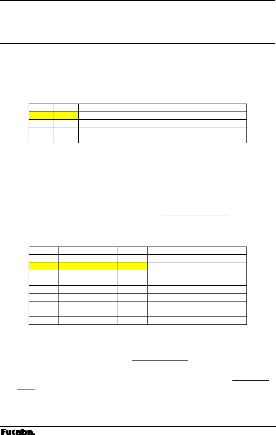
Page 78 FRH-SD07TU/TB Manual
Rev. 020510-01
REG27: Frequency Band Settings [default value: 01H]
Bit 7 – 6: reserved
• The FRH-SD07TU/TB does not use this register. Keep the default value as it is.
Bit 5 – 4: Output clock rate of AUX terminal
Bit 5 Bit 4 Setting
0 0 No clock output (default value)
0 1 100KHz
1 0 1.14MHz
1 1 8MHz
Table 5–30: Setting of output clock rate of AUX terminal
• Sets the operation clock rate of the output signal of the AUX terminal for the status
monitor use. Some of the status data contains high speed one-shot signals, which requires
high speed clock to properly catch. Because of higher current consumption when higher
clock rate, this parameter controls the clock rate to decrease current consumption.
• For the function of the AUX terminal, refer to p.151 AUXILIARY INTERFACE.
Bit 3 – 0: Frequency band setting
Bit 3 Bit 2 Bit 1 Bit 0 Setting
0 0 0 0 Invalid (forced to 0001)
0 0 0 1 2433-2479MHz (default value)
0 0 1 0 Do not set (Invalid)
0 0 1 1 01 Band
0 1 0 0 02 Band
0 1 0 1 2420-2466MHz 2MHz Separation
0 1 1 0 2423-2469MHz 2MHz Separation
0 1 1 1 Reserved
1 - - -
Table 5–31: Frequency band setting
• For the frequency band, refer to p.35 FREQUENCY BAND.
• For the FRH-SD07TB users in France and Spain, frequency usage is restricted to 02
Band because of its country’s regulatory authority. Also please refer p.35 FREQUENCY
BAND. for its details.

Page 79
Futaba Corporation Rev. 020510-01
6
SECTION
6 COMMAND SET DESCRIPTION
CONTENTS
6 COMMAND SET DESCRIPTION.......................................................................79
6.1 COMMAND SET DESCRIPTION ................................................................................................... 80
ARG REFERENCE ALL MEMORY REGISTERS.................................................................................. 82
BCL CLEAR TRANSMIT AND RECEIVE BUFFERS ............................................................................. 83
BIV REFERENCE AND SET BEACON INTERVALS ............................................................................ 84
BST READ BUFFER STATUS ......................................................................................................... 85
DAS REFERENCE AND SET DESTINATION ADDRESS ....................................................................... 86
DBM READ SIGNAL STRENGTH...................................................................................................... 87
FRQ REFERENCE AND SET FREQUENCY GROUP............................................................................ 88
INI INITIALIZE ALL MEMORY REGISTERS ...................................................................................... 89
ODA DISABLE RECEIVED DATA OUTPUT ........................................................................................ 90
OEN ENABLE RECEIVED DATA OUTPUT ......................................................................................... 91
PAS REFERENCE AND SET REPEATER ADDRESS........................................................................... 92
POF TRANSMIT DIRECTLY TO RECEIVER ....................................................................................... 93
PON TRANSMIT THROUGH REPEATER............................................................................................ 94
RBC CLEAR RECEIVE BUFFER ...................................................................................................... 95
RDA DISABLE WIRELESS RECEPTION............................................................................................ 96
REG REFERENCE AND SET MEMORY REGISTER............................................................................. 97
REN RECEPTION ENABLE ............................................................................................................. 98
RID DISPLAY RECEIVED SERIAL ID............................................................................................... 99
RLR RELEASE ULTRA MODE THROUGH REPEATER.................................................................... 100
RLU RELEASE ULTRA MODE (DIRECT)...................................................................................... 101
RNO REFERENCE AND SET RETRANSMISSION COUNT .................................................................. 102
ROF RF CIRCUIT BLOCK POWER DOWN ..................................................................................... 103
RON RF CIRCUIT BLOCK POWER UP........................................................................................... 104
RPT RETRANSMIT MESSAGE ...................................................................................................... 105
RST RESET ...............................................................................................................................106
RTY RETRANSMIT MESSAGE THROUGH REPEATER ..................................................................... 107
STS READ STATUS..................................................................................................................... 108
TBC CLEAR TRANSMIT BUFFER .................................................................................................. 109
TBN TRANSMIT BINARY DATA..................................................................................................... 110
TBR TRANSMIT BINARY DATA THROUGH REPEATER..................................................................... 111
TID DISPLAY LOCAL STATION SERIAL ID .................................................................................... 112
TXR TRANSMIT TEXT DATA THROUGH REPEATER........................................................................ 113
TXT TRANSMIT TEXT DATA ........................................................................................................ 114
VER REFERENCE VERSION INFORMATION ................................................................................... 115

Page 80 FRH-SD07TU/TB Manual
Rev. 020510-01
6.1 Command Set Description
This section provides a description of each command available in the FRH command set.
The table below lists each command and it applicability in each operation mode.
Command Function Command to Mode
Availability
3 4 5 6
1 ARG Reference All Memory Resisters
2 BCL Clear Transmit and Receive Buffers — —
3 BIV Reference and Set Beacon Interval —
—
4 BST Read Buffer Status — —
5 DAS Reference and Set the Destination Address — — —
6 DBM Read Signal Strength — —
7 FRQ Reference and Set Frequency Group —
8 INI Initialize All Memory Resisters
9 ODA Disable Received Data Output — —
10 OEN Enable Received Data Output — —
11 PAS Reference and Set Repeater Address — — —
12 POF Transmit Directly to Receiver — — —
13 PON Transmit through Repeater — — —
14 RBC Clear Receive Buffer — —
15 RDA Disable Wireless Reception — —
16 REG Reference and Set Memory Resisters
17 REN Enable Wireless Reception — —
18 RID Display Received Serial ID — —
19 RLR Release ULTRA Mode Through Repeater — —
20 RLU Release ULTRA Mode (Direct) — —
21 RNO Reference and Set Retransmission Count — —
22 ROF RF Circuit Block Power Down
23 RON RF Circuit Block Power Up
24 RPT Retransmit Message — —
25 RST Reset
26 RTY Retransmit Message Through Repeater — — —
27 STS Read Status — —
28 TBC Clear Transmit Buffer — —
29 TBN Transmit Binary Data — — —
30 TBR Transmit Binary Data Through Repeater — — —
31 TID Display Local Station Serial ID —
32 TXR Transmit Text Data Through Repeater — — —
33 TXT Transmit Text Data — — —
34 VER Reference Version Information
= available
— = unavailable or invalid
Table 6–1: Command to Mode Availability

Page 81
Futaba Corporation Rev. 020510-01
The symbols used in this section have the following meaning:
> : Input character from the terminal equipment to the modem
< : Output from the modem to the terminal equipment
@ : Command header
CR/LF : Terminator (carriage return + line feed)
[ ] : Required input parameter/s Be sure to input.
( ) : Optional input parameter/s May be omitted
{} : 485 mode local station address (REG00). Be sure to
input at 485 mode
In the Syntax and Response segments of the following command descriptions the terminator
symbol (CR/LF) has been omitted for clarity.

Page 82 FRH-SD07TU/TB Manual
Rev. 020510-01
ARG Reference All Memory Registers
Syntax
ARG{Local Station Address}
Local Station Address : local station address for 485 mode (000 to 239).
Response
All settings are indicated (REG00 to REG27)
N0: command error (Except 485 mode)
Function
Recalls the contents of all 28 memory registers.
Example
>
@ARG CR/LF : Recall the contents of all the memory registers
<REG00 : 01H CR/LF : Consecutive output of register contents
<REG01 : F0H CR/LF : Register values output in hexadecimal codes
<REG02 : 02H CR/LF
<REG03 : F1H CR/LF
|
|
<REG22 : 00H CR/LF
<REG23 : 00H CR/LF

Page 83
Futaba Corporation Rev. 020510-01
BCL Clear Transmit and Receive Buffers
Syntax
BCL{Local Station Address}
Local Station Address : local station address for 485 mode (000 to 254).
Response
P0 : command accepted
N0 : command error (Except 485 mode)
Function
On headerless packet mode (mode 5), clears the contents of the transmit and
receive buffers of the modem.
Example
>
@BCL CR/LF : clear the buffer contents
<P0
CR/LF : command accepted
Notes
Use the TBC or RBC command to clear only the contents of either transmit or
receive buffers.

Page 84 FRH-SD07TU/TB Manual
Rev. 020510-01
BIV Reference and Set Beacon Intervals
Syntax
BIV(Interval) {; Local Station Address}
Interval : Specifies 000 to 065, in 10msec increment.
Local Station Address : local station address for 485 mode (000 to 239).
Response
xxx : current set value (reference)
P0 : command accepted (setting)
N0 : command error (Except 485 mode)
Function
Set the interval of the radio beacon transmission/receiving function. Refer to p.51
COMMUNICATION EXAMPLE (N:M-MODE 3).
The current value can be referred by issuing the command only. In case of setting,
input the desired value for setting.
In the radio beacon transmission function status (REG19:bit 1=1), the beacon
transmission interval can be set. In the beacon receiving function status
(REG19:bit 2=1), the beacon receiving interval can be set.
BIV command is used for temporarily changing the interval. The default values are
fixed at 500 ms for the receiving interval and 150 ms for the transmission interval.
The default value is reloaded at the power on or reset operation.
Example
>@BIV025 CR/LF : Set the receiving (transmission) interval at 250 ms
<P0 CR/LF : command accepted
>@BIV CR/LF : Refer the current value
<025 CR/LF : 025 (25 0ms) returns
Notes Values set by the BIV command will be lost by turning the power on or resetting.
Generally, this parameter is no need to modifying. Use with the default value.
Page 85
Futaba Corporation Rev. 020510-01
BST Read Buffer Status
Syntax
BST{Local Station Address}
Local Station Address : local station address for 485 mode (000 to 239).
Response
xxxxxxxx : current status (x : 0 or 1)
N0 : command error (Except 485 mode)
Function
Reads buffers status of the modem. (Represented with an 8-bit binary number.)
bit 7 bit 6 bit 5 bit 4 bit 3 bit 2 bit 1 bit 0
0 buffer empty
1 data in buffer
0 buffer avalable
1 buffer full
0 no overflow
1 buffer overflow
0 reserved
0 buffer empty
1 data in buffer
0 buffer available
1 buffer full
0 enabled
1 disabled
0 reserved
Buffer Status
transmit buffer
transmit buffer
transmit buffer
receive buffer
receive buffer
receive data output
Figure 5–1: Buffer Status Bit Description
Example
>
@BST CR/LF : read the buffer status register
<00000001 CR/LF : transmit buffer contains data

Page 86 FRH-SD07TU/TB Manual
Rev. 020510-01
DAS Reference and Set Destination Address
Syntax
DAS(set destination address)
set destination address : the desired destination address (000 to 239)
Response
xxx : current value (reference)
P0 : command accepted (setting)
N0 : command error
Function
References or sets the destination address of the modem connection established
with in the headerless transmission mode (mode 5)
The current DAS value can be referenced by entering the command with no
parameter.
The DAS command is used for temporary modifying destination address. Change
the value of REG02 to change the default value.
Example
>
@DAS002 CR/LF : set the destination address to 002
<P0
CR/LF : command accepted
>
@DAS CR/LF : reference the destination address
<002
CR/LF : current value output (002)
Notes
This command cannot be used in packet transmission mode.
The local station address (REG00) must be set to communicate with the remote
modem. Communication cannot be established unless the addresses coincide with
each other.
This command is not arrowed to use in 485 mode.

Page 87
Futaba Corporation Rev. 020510-01
DBM Read Signal Strength
Syntax
DBM{Local Station Address}
Local Station Address : local station address for 485 mode (000 to 239).
Response
-xxxdBm : signal strength
N0 : command error (Except 485 mode)
Function
Reads the received signal strength and outputs the value in dBm.
Higher values represent stronger signal strength and better receiving conditions.
Example
>
@DBM CR/LF : read signal strength
<-78dBm
CR/LF : signal strength is -78dBm.
Notes
The range available for measurement is –40 dBm to –100 dBm. Since the signal
strength indication has a slight error in its value, use this result for your ‘rule of a
thumb’ reference.
This command outputs the strength of last received packet.
Page 88 FRH-SD07TU/TB Manual
Rev. 020510-01
FRQ Reference and Set Frequency Group
Syntax
FRQ(:frequency group){Local Station Address}
frequency group : combination of frequency grouping method (A to H)
and group number (00 to 23). See p.35 FREQUENCY
GROUPING more details.
Local Station Address : local station address for 485 mode (000 to 239 for
reference, 000 to 254 for setting).
Response
xxx : current value
P0 : command accepted
N0 : command error (Except 485 mode)
Function
References or sets the frequency grouping method and group number.
The current set value is referenced by omitting the “:frequency group” parameter
This command is for temporary use only. To change the default value, change the
settings of REG06.
Example
>
@FRQ CR/LF : reference the current grouping method and frequency number
<F00
CR/LF : output current value (grouping method F: group number 00)
>@FRQ:E03 CR/LF : set grouping method to E (6 groups) and group number to 3.
<P0
CR/LF : command accepted
Table 5–2: Grouping Methods and Numbers
Method Number of
Groups Available Group
Number Settings Frequencies
per Group
A 1 0 24
B 2 0 to 1 12
C 3 0 to 2 8
D 4 0 to 3 6
E 6 0 to 5 4
F 8 0 to 7 3
G 12 0 to 11 2
H 24 0 to 23 1
Notes
Do not change this setting while the modem is being transmitted.
The maximum number of frequency groups available depends upon the selected
grouping method.

Page 89
Futaba Corporation Rev. 020510-01
INI Initialize All Memory Registers
Syntax
INI{Local Station Address}
Local Station Address : local station address for 485 mode (000 to 254).
Response
P0 : command accepted
N0 : command error (Except 485 mode)
Function
Sets the all contents of the memory registers to the factory default values.
Example
>
@INI CR/LF : initialize all memory registers
<P0
CR/LF : command accepted
Notes
Custom settings of all memory registers are lost when this command is executed.
If the global address (240 to 254) is designated while RS485 multi-drop connection
is being made in the RS485 mode, the local station address of all modems will be
initialized to 000. Exercise care when issuing this command.
For a list of the factory default values, see the section titled p.59 MEMORY
REGISTER
DESCRIPTION.

Page 90 FRH-SD07TU/TB Manual
Rev. 020510-01
ODA Disable Received Data Output
Syntax
ODA{Local Station Address}
Local Station Address : local station address for 485 mode (000 to 254).
Response
P0 : command accepted
N0 : command error (Except 485 mode)
Function
Disables output of any data received via the wireless link to the terminal equipment.
Data received, while output is disabled, is stored in the receive buffer.
When the modem’s power is turned on (or a reset), the modem is in the state to
enable the received data output.
Example
>
@ODA CR/LF : disable the output of received wireless data
<P0
CR/LF : command accepted
(Data is not output during this period even if received.)
>
@OEN CR/LF : enable the output of received wireless data.
<P0
CR/LF : command accepted
<RXT002HELLO
CR/LF : outputs data stored in the receive buffer
<RXT003MAIL
CR/LF :

Page 91
Futaba Corporation Rev. 020510-01
OEN Enable Received Data Output
Syntax
OEN{Local Station Address}
Local Station Address : local station address for 485 mode (000 to 254).
Response
P0 : command accepted
N0 : command error (Except 485 mode)
Function
Enables output of any data received via the wireless link to the terminal equipment.
This command enables serial data output after it has been disabled with the ODA
command.
When the modem’s power is turned on (or a reset), the modem is in the state to
enable the received data output.
Example
>
@ODA CR/LF : disable serial output of received wireless data
<P0
CR/LF : command accepted
(Data is not output during this period even if received.)
>
@OEN CR/LF : enable serial output of received wireless data.
<P0
CR/LF : command accepted
<RXT002HELLO
CR/LF : outputs data stored in receive buffer
<RXT003MAIL
CR/LF : and any new data received

Page 92 FRH-SD07TU/TB Manual
Rev. 020510-01
PAS Reference and Set Repeater Address
Syntax
PAS (Repeater Address)
Repeater Address : repeater address to pass through
Response
xxx : current address (reference)
P0 : command accepted (setting)
N0 : command error
Function
In the headerless packet transmission mode (mode 5), references and sets the
repeater address to pass through
When no repeater address is set, the current setting can be referenced.
This command is used to temporarily change repeater address. To change the
default value, change REG13.
Example
>
@PAS CR/LF : references the current repeater address
<000
CR/LF : current repeater address is 000
<P0
CR/LF : command accepted
<
@PAS002 CR/LF : sets the repeater address to 002
<P0
CR/LF : command accepted
Notes
This command is not allowed to be used in 485 mode.

Page 93
Futaba Corporation Rev. 020510-01
POF Transmit Directly to Receiver
Syntax
POF
Response
P0 : command accepted
N0 : command error
Function
In the headerless packet transmission mode (mode 5), transmits directly to
receiver without passing through the repeater.
This command is used for temporary change of the path. To change the default value,
change bit 5 of REG18.
Example
>
@PON CR/LF : sets the transmission path through repeater
<P0
CR/LF : command accepted
<
@POFCR/LF : sets to direct transmission to receiver modem
<P0
CR/LF : command accepted
Notes
This command is not allowed to be used in 485 mode.

Page 94 FRH-SD07TU/TB Manual
Rev. 020510-01
PON Transmit through Repeater
Syntax
PON
Response
P0 : command accepted
N0 : command error
Function
In the headerless packet transmission mode (mode 5), transmits through
repeater.
This command is used for temporary change of path. To change the default value,
change bit 5 of REG18.
Example
>
@PON CR/LF : sets the transmission path through repeater
<P0
CR/LF : command accepted
<
@POFCR/LF : sets to direct transmission to receiver modem
<P0
CR/LF : command accepted
Notes
This command is not allowed to be used in 485 mode.

Page 95
Futaba Corporation Rev. 020510-01
RBC Clear Receive Buffer
Syntax
RBC{Local Station Address}
Local Station Address : local station address for 485 mode (000 to 254).
Response
P0 : command accepted
N0 : command error (Except 485 mode)
Function
On headerless packet mode (mode 5), clears the contents of the receive buffer.
Example
>
@RBC CR/LF : clear the contents of the receive buffer
<P0
CR/LF : command accepted
Notes
To clear both transmit and receive buffers, use the BCL command.

Page 96 FRH-SD07TU/TB Manual
Rev. 020510-01
RDA Disable Wireless Reception
Syntax
RDA{Local Station Address}
Local Station Address : local station address for 485 mode (000 to 254).
Response
P0 : command accepted
N0 : command error (Except 485 mode)
Function
Disables wireless reception in the packet transmission mode.
The status when the modem is powered ON or reset follows bit 7 of REG22.
Example
>
@RDA CR/LF : disable wireless reception
<P0
CR/LF : command accepted
>
@REN CR/LF : enable wireless reception
<P0
CR/LF : command accepted

Page 97
Futaba Corporation Rev. 020510-01
REG Reference and Set Memory Register
Syntax
REG[register number](: value) {;Local Station Address}
register number : register number to be set (00 to 23)
value : value to be set. Input 2 hexadecimal digits (0 through 9
and A through F) followed by the number radix
designator H.
Local Station Address : local station address for 485 mode (000 to 239 for
reference, 000 to 254 for setting).
Response
xxH : current value (reference)
P0 : command accepted (setting)
N0 : command error (Except 485 mode)
N6 : memory register write error
Function
References or sets memory registers.
The current register value is referenced by omitting the “value” parameter.
Example
>
@REG00 CR/LF : reference the contents of register 00
<01H
CR/LF : displays current value
>
@REG00 : 02H CR/LF : set value of memory register 00 to 02H (hexadecimal)
<P0
CR/LF : command accepted
Notes
The register can be rewritten sequentially. However, to make its parameter valid
after rewriting it, re-supply the power, reset the modem using the Shutdown mode
pin (Pin 11 of the serial communication connector) or use RST command.
While rewriting the memory register, do not turn off the power until response is
output. Otherwise, the memory registers content may be collapsed.
When the response of the memory register write error is output, set the values
after initializing the memory register.

Page 98 FRH-SD07TU/TB Manual
Rev. 020510-01
REN Reception Enable
Syntax
REN{Local Station Address}
Local Station Address : local station address for 485 mode (000 to 254).
Response
P0 : command accepted
N0 : command error (Except 485 mode)
Function
Enables wireless reception in the packet transmission mode.
The status when the modem is powered ON or reset follows bit 7 of REG22.
Use this command to enable wireless reception after reception is disabled with the
RDA command.
Example
>
@RDA CR/LF : disable wireless reception
<P0
CR/LF : command accepted
>
@REN CR/LF : enable wireless reception.
<P0
CR/LF : command accepted

Page 99
Futaba Corporation Rev. 020510-01
RID Display Received Serial ID
Syntax
RID{Local Station Address}
Local Station Address : local station address for 485 mode (000 to 239).
Response
XXXXXXXXXXXX : displays the received serial ID code(12 digits)
N0 : command error (Except 485 mode)
Function
Outputs the serial ID code in the received packet and displays it.
The serial ID code consists of 12 digits; upper three digits are 0 and the lower 9
digits are the product serial number of the transmitted-end modem.
Be noted that the serial ID code of the packet received last is displayed. When
packets are received from multiple stations and their data are stored in the receiving
buffer, those data may not be correspond to the serial ID code readout with RID
command.
To use it more securely, it is recommended to readout the local serial ID code with
TID command and pad it (either all or a part of it) in the transmitting packet.
When no packet is received, “All Zero” is displayed as the result of this command
execution.
The serial ID code is no relation with ID code setting of REG04 and 05.
Example
>
@RID CR/LF : requests the received remote station’s serial ID code
< XXXXXXXXXXXX
CR/LF :outputs the received remote station’s serial ID code

Page 100 FRH-SD07TU/TB Manual
Rev. 020510-01
RLR Release ULTRA Mode Through Repeater
Syntax
RLR [repeater address] [destination address]{Local Station Address}
repeater address : address of repeater to pass through (000 to 239)
destination address : address of destination station (000 to 239, set to 255 for
broadcast ULTRA mode release)
Local Station Address : local station address for 485 mode (000 to 254).
Response
P1 : command accepted. Transmitting, the request to release the ULTRA
mode through the repeater.
P0 : Broadcast ULTRA mode release request transmission complete
N0 : command error (Except 485 mode)
N1 : ULTRA mode release request transmission complete
Function
Makes the destination station(s) in the ULTRA (Ultra Low-power Transient
Radio Access) mode return to the Active mode by transmitting ULTRA wakeup
request packet from the repeater. Local modem just send the request to the
repeater.
At the command completion, “N1” response is output from in any case (P1 to
broadcast case). To confirm that the destination station returns to the Active
mode, attempt communication with the destination station using TXR command.
Example
>
@RLR100001 CR/LF : transmitting to Station 001 the request to release the
ULTRA mode from the repeater 100.
<P1
CR/LF : transmitting the Wakeup transmission request signal
<N1
CR/LF : request signal transmission completes (unknown
whether succeeded or failed)
>
@ RLR100255 CR/LF : transmits the broadcast request signal to release the
ULTRA mode
<P1
CR/LF : transmitting the request signal
< P0 CR/LF : request signal transmission completes (unknown
whether succeeded or failed)

Page 101
Futaba Corporation Rev. 020510-01
RLU Release ULTRA Mode (Direct)
Syntax
RLU [destination address]{Local Station Address}
destination address : address of destination station (000 to 239, set to 255 for
all station) to ULTRA mode release
Local Station Address : local station address for 485 mode (000 to 254).
Response
P0 : ULTRA mode successfully released
P1 : command received.
transmitting the Wakeup request packet of the ULTRA mode
N0 : command error (Except 485 mode)
N1 : failed in releasing the ULTRA mode (no response from the
destination station)
Function
Makes the destination station(s) in the ULTRA (Ultra Low-power Transient
Radio Access) mode return to the Active mode by transmitting Wakeup request
packet, ULTRA mode release signal.
In case of all station’s ULTRA mode release (broadcast), the modem outputs “P0”
response in any case. To confirm that the destination station returns to the Active
mode, attempt communication with the destination station using TXT command.
When the destination station, its REG 25:bit 7 is set to 1 which allows the ULTRA
mode operation, but operating in the Active mode, will return “release success
ACK” when it receives the Wakeup request packet , ULTRA mode release signal.
Therefore, the response to the RLU command is “P0”.
Example
>
@RLU001 CR/LF : transmitting to Station 001 Wakeup request packet,
the request to release the ULTRA mode
<P1
CR/LF : transmitting the Wakeup request packet
<N1
CR/LF : release failed
>
@ RLU002 CR/LF : transmits to Station 001 the Wakeup request packet
<P1
CR/LF : transmitting the Wakeup request packet
<P0
CR/LF : release succeeded
>
@ RLU255 CR/LF : transmits to all stations Wakeup request packet
<P1
CR/LF : transmitting the Wakeup request packet
<P0
CR/LF : transmission of Wakeup request packet completes
(unknown whether it is succeeded or failed)

Page 102 FRH-SD07TU/TB Manual
Rev. 020510-01
RNO Reference and Set Retransmission Count
Syntax
RNO (retransmission count) {; Local Station Address}
retransmission count : maximum number of retransmissions (000 to 255)
Local Station Address : local station address for 485 mode (000 to 239 for
reference, 000 to 254 for setting).
Response
xxx : current set value
P0 : command accepted
N0 : command error (Except 485 mode)
Function
This command references or sets the number of retransmissions (retransmission
count) to attempt before making decision as transmission failure.
The current value can be referenced by issuing the command with no parameter.
RNO command is used to temporarily change the retransmission count. To
change the default value, change the setting of REG11.
Example
>
@RNO CR/LF : reference the retransmission count
<050
CR/LF : output the current set value (50 times)
>
@RNO010 CR/LF : set the retransmission count to 10 times
<P0
CR/LF : command accepted

Page 103
Futaba Corporation Rev. 020510-01
ROF RF Circuit Block Power Down
Syntax
ROF{Local Station Address}
Local Station Address : local station address for 485 mode (000 to 254).
Response
P0 : command accepted
N0 : command error (Except 485 mode)
Function
Turn off the power of RF circuit block and stops RF operation.
This function is used to save the current consumption when no transmit/receive are
required. The current consumption in this mode is about 5 mA.
Example
>
@ROF CR/LF : turn off RF circuit block
<P0
CR/LF : command accepted
>
@RON CR/LF : turn on RF circuit block
<P0
CR/LF : command accepted

Page 104 FRH-SD07TU/TB Manual
Rev. 020510-01
RON RF Circuit Block Power Up
Syntax
ROF{Local Station Address}
Local Station Address : local station address for 485 mode (000 to 254).
Response
P0 : command accepted
N0 : command error (Except 485 mode)
Function
Turn on the power of RF circuit block and activates RF operation.
Use this command to activate RF circuit block after its power down state set by the
ROF command.
The status when the modem is powered ON or reset, the RF circuit block is in the
operation state.
Example
>
@ROF CR/LF : turn off RF circuit block
<P0
CR/LF : command accepted
>
@RON CR/LF : turn on RF circuit block
<P0
CR/LF : command accepted

Page 105
Futaba Corporation Rev. 020510-01
RPT Retransmit Message
Syntax
RPT [destination address]{Local Station Address}
destination address : address of destination station (000 to 239)
set 240 to 254 for global addressed destination
set 255 for broadcast transmission
Local Station Address : local station address for 485 mode (000 to 254).
Response
P0 : data transmission succeeded
P1 : command accepted, data being transmitted.
P2 : data packet reached to repeater
N0 : command error (Except 485 mode)
N1 : data transmission failed -- no response from destination station
N2 : data transmission failed -- destination station is in the reception disabled state
N3 : data transmission failed -- destination station cannot receive because its receive
buffer is full
Function
Retransmits the last message.
Use this command to retransmit the same data or transmit the same data to a different
station.
For broadcasting messages to multiple modems, set the destination address to 255.
In this case, the modem retransmit the message the number of times of the
Retransmission count plus 1, and then it will return “P0”.
Example
>@TXT002HELLO
CR/LF : transmit “HELLO” from station 001 to station 002
<P1
CR/LF : data being transmitted
<N1
CR/LF : transmission failed.
>@RPT002
CR/LF : retransmit “HELLO” from station 001 to station 002
<P1
CR/LF : data being transmitted
<P0
CR/LF : data transmission succeeded
>@RPT003
CR/LF : transmit “HELLO” from station 001 to station 003
<P1
CR/LF : data being transmitted
<P0
CR/LF : data transmission succeeded
Notes
Follow the last transmit command’s form of transmission, text or binary, or whether
passing through repeater or not.
In case of broadcast transmission, the receiving result of the destination station
cannot be confirmed at the sender end.
Before invoking this command, execute any transmit command of TXT, TXR, TBN,
or TBR.
There are important notes using transmit commands. Be sure to read p.158
OPERATION IMPORTANT NOTICE.

Page 106 FRH-SD07TU/TB Manual
Rev. 020510-01
RST Reset
Syntax
RST{Local Station Address}
Local Station Address : local station address for 485 mode (000 to 254).
Response
P0 : command accepted
N0 : command error (Except 485 mode)
Function
Resets the modem to restore the power on state.
When any memory register is rewritten with REG command before issuing this
command, the value rewritten becomes valid and active. Temporary settings like
DAS and FRQ command become invalid and the memory register settings is
loaded.
Example
>
@RST CR/LF : reset the modem
<P0
CR/LF : command accepted
Note When a serial communication parameter in memory register is changed with REG
command, the response of “P0” returns according to the changed setting parameter,
which may cause communication error. In such a case, set the communication
parameter of the terminal equipment in correspondence with the new setting
immediately after the issuance of RST command.

Page 107
Futaba Corporation Rev. 020510-01
RTY Retransmit Message Through Repeater
Syntax
RTY [repeater address] {Local Station Address}
repeater address : address of repeater to pass through for message
transmission (000 to 239)
Local Station Address : local station address for 485 mode (000 to 254).
Response
P0 : data transmission succeeded
P1 : command accepted, data being transmitted.
P2 : data packet reached to repeater
N0 : command error (Except 485 mode)
N1 : data transmission failed -- no response from destination station
N2 : data transmission failed -- destination station is in the reception
disabled state
N3 : data transmission failed -- destination station cannot receive because
its receive buffer is full
Functions
Retransmits the previous message to the same destination station through a
repeater.
In case the global addressing command is issued to plural modems connected by
RS485 multi-dropping interface, the transmission stops when any modem outputs
“P0”, “N2” or “N3” response to the RS485 line.
Example
>
@TXT002HELLO CR/LF : transmit “HELLO” from station 001 to station 002
<P1
CR/LF : command received, data transmitted
<N1
CR/LF : transmission failed
>
@RTY100 CR/LF : retransmit “HELLO” from station 001 to station 002
through repeater 100
<P1
CR/LF : data being transmitted
<P2
CR/LF : data packet reached to repeater
<P0
CR/LF : data transmission succeeded
Notes
Before invoking this command, execute any transmit command of TXT, TXR, TBN,
or TBR.
In case of broadcast transmission, the receiving result of the destination station
cannot be confirmed at the sender end.
There are important notes using transmit commands. Be sure to read p.158
OPERATION IMPORTANT NOTICE.
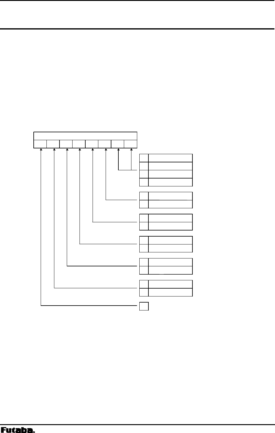
Page 108 FRH-SD07TU/TB Manual
Rev. 020510-01
STS Read Status
Syntax
STS{Local Station Address}
Local Station Address : local station address for 485 mode (000 to 239).
Response
xxxxxxxx : modem’s current status (x = 0 or 1)
N0 : command error (Except 485 mode)
Function
Reads the modem status register. (Represented with an 8-bit binary number.)
bit 7 bit 6 bit 5 bit 4 bit 3 bit 2 bit 1 bit 0
00 Mode 1
01 Mode 2
10 Mode 3
11 Mode 4
0 enabled
1 disabled
0 enabled
1 disabled
0 buffer available
1 buffer full
0 no overflow
1 buffer overflow
0 disconnected
1 connected
0 reserved
Modem Status
wireless reception
receive data output
receive buffer
transmit buffer
wireless link
operation mode
Figure 6–2: Modem Status Bit Description
Example
>
@STS CR/LF : read the current status
<00001010 CR/LF : Operation Mode 3, receive data output disabled
Notes
Bit 6, the wireless link status, this bit does not valid in the modem.

Page 109
Futaba Corporation Rev. 020510-01
TBC Clear Transmit Buffer
Syntax
TBC{Local Station Address}
Local Station Address : local station address for 485 mode (000 to 254).
Response
P0 : command accepted
N0 : command error (Except 485 mode)
Function
In the headerless packet mode (mode 5), clear the contents of the transmit buffer.
Example
>TBC
CR/LF : clear the contents of the transmit buffer
<P0
CR/LF : command accepted
Notes
Use the BCL command to clear both the transmit and receive buffers.

Page 110 FRH-SD07TU/TB Manual
Rev. 020510-01
TBN Transmit Binary Data
Syntax
TBN[destination address][message byte length]{Local Station Address}[message]
Destination address : address of the broadcast transmission (000 to 239)
set 240 to 254 for global addressed destination
set 255 for broadcast transmission
Message byte length : message length (001 to 255)
Local Station Address : local station address for 485 mode (000 to 254).
Message byte : arbitrary binary data (255 or less)
Response
P0 : data transmission succeeded
P1 : command accepted, data being transmitted
N0 : command error (Except 485 mode)
N1 : data transmission failed -- no response from destination station
N2 : data transmission failed -- destination station is in the reception disabled state
N3 : data transmission failed -- destination station cannot receive because its receive
buffer is full
Function
Transmits binary data in the packet transmission mode.
Any message length between 1 to 255 bytes is accepted.
The modem counts the number of message characters and transmits the message.
For broadcasting messages to multiple modems, set the destination address to 255.
In this case, the modem retransmits the message the number of times of the
Retransmission count plus 1, and then it will return “P0”.
In case the global addressing command is issued to plural modems connected by
RS485 multi-dropping interface, the transmission stops when any modem outputs
“P0”, “N2” or “N3” response to the RS485 line.
Example
>TBN002005HELLO
CR/LF : transmit “HELLO” from station 001 to station 002
<P1
CR/LF : data being transmitted
<P0
CR/LF : data transmission succeeded.
>@TBN003004MAIL
CR/LF : retransmit “MAIL” from station 001 to station 003
<P1
CR/LF : data being transmitted
<N1 CR/LF : transmission failed, no response from destination station
Notes
Set the message length to 255 byte or less. The message length exceeding 255
byte will be command error.
Message must be terminated with 2 byte (CR/LF) character, others will be command
error.
In broadcast transmission, the receiving result of the destination station cannot
be confirmed at the sender side.
There are important notes using transmit commands. Be sure to read p.158
OPERATION IMPORTANT NOTICE.

Page 111
Futaba Corporation Rev. 020510-01
TBR Transmit Binary Data through Repeater
Syntax
TBR [repeater address] [destination address] [message byte length]{Local Station
Address}[message]
Repeater address : repeater address to pass through (000 to 239)
Destination address : address of destination station (000 to 239)
set 240 to 254 for global addressed destination
set 255 for broadcast transmission
Message byte length : message byte length (001 to 255)
Local Station Address : local station address for 485 mode (000 to 254).
Message byte : arbitrary binary data (255 or less)
Response
P0 : data transmission succeeded
P1 : command accepted, data being transmitted
P2 : data packet reached to repeater
N0 : command error (Except 485 mode)
N1 : data transmission failed -- no response from destination station
N2 : data transmission failed -- destination station is in the reception disabled state
N3 : data transmission failed -- destination station cannot receive because its receive
buffer is full
Function
In the packet transmission mode, transmits binary data through repeater.
Any message length between 1 to 255 bytes is accepted.
The modem counts the number of message characters and transmits the message.
For broadcasting messages to multiple modems, set the destination address to 255.
In this case, the modem retransmits the message the number of times of the
Retransmission count plus 1, and then it will return “P0”.
In case the global addressing command is issued to plural modems connected by
RS485 multi-dropping interface, the transmission stops when any modem outputs
“P0”, “N2” or “N3” response to the RS485 line.
Example
>TBR100002005HELLO
CR/LF : transmit “HELLO” from station 001 to station 002
<P1
CR/LF : data being transmitted
<P2 CR/LF : data packet reached to repeater
<P0
CR/LF : data transmission succeeded
Notes
Set the message length to 255 byte or less. The message length exceeding 255
byte will be command error.
Message must be terminated with 2 byte (CR/LF) character, others will be command
error.
In broadcast transmission, the receiving result of the destination station cannot
be confirmed at the sender side.
There are important notes using transmit commands. Be sure to read p.158
OPERATION IMPORTANT NOTICE.

Page 112 FRH-SD07TU/TB Manual
Rev. 020510-01
TID Display Local Station Serial ID
Syntax
TID{Local Station Address}
Local Station Address : local station address for 485 mode (000 to 239).
Response
XXXXXXXXXXXX : displays the local serial ID code (12 digits)
N0 : command error (Except 485 mode)
Function
Readout the local serial ID code of the modem and display it. This command
corresponds to RID command.
The local serial ID code consists of 12 digits; upper three digits are 0 and the lower
9 digits are the product serial number of the modem.
Be noted the usage of RID command, the serial ID code of the packet received last
is displayed. When packets are received from multiple stations and their data are
stored in the receiving buffer, those data may not correspond to the serial ID code
readout with the RID command.
To use it more securely, it is recommended to readout the local serial ID code with
the TID command and pad it (either all or a part of it) in the transmitting packet.
The serial ID code is no relation with ID code setting of REG04 and 05.
Example
>
@TID CR/LF : requests the modem’s local serial ID code
< XXXXXXXXXXXX
CR/LF :outputs the modem’s local serial ID code

Page 113
Futaba Corporation Rev. 020510-01
TXR Transmit Text Data through Repeater
Syntax
TXR [repeater address] [destination address]{Local Station Address}[message]
repeater address : address of repeater to pass through (000 to 239)
destination address : address of destination station (000 to 239)
set 240 to 254 for global addressed destination
set 255 for broadcast transmission
Local Station Address : local station address for 485 mode (000 to 254).
message : any text data (255 or less)
Response
P0 : data transmission succeeded
P1 : command accepted, data being transmitted
P2 : data packet reached to repeater
N0 : command error (Except 485 mode)
N1 : data transmission failed -- no response from the destination station
N2 : data transmission failed -- destination station is in the reception disabled state
N3 : data transmission failed -- destination station cannot receive because its receive
buffer is full.
Function
Transmits text data in the packet transmission mode through repeater.
Any message length between 1 to 255 bytes is accepted. The completion of data
input is recognized by the terminator.
For broadcasting messages to multiple modems, set the destination address to 255.
In this case, the modem retransmits the message the number of times of the
Retransmission count plus 1, and then it will return “P0”.
In case the global addressing command is issued to plural modems connected by
RS485 multi-dropping interface, the transmission stops when any modem outputs
“P0”, “N2” or “N3” response to the RS485 line.
Example
>@TXR100002HELLO CR/LF : transmits HELLO from station 001 to station 002 through
repeater 100
<P1
CR/LF : data being transmitted
<P2
CR/LF : data packet reached to repeater
<P0
CR/LF : data transmission succeeded
Notes
Set the message length to 255 byte or less. The message length exceeding 255
byte will be command error.
When the same character as the terminator (CR/LF) is contained in a message, the
modem distinguishes it as the end of a command and ignore the subsequent data. In
such a case, use TBR command.
In broadcast transmission, the receiving result of the destination station cannot
be confirmed at the sender side.
There are important notes using transmit commands. Be sure to read p.158
OPERATION IMPORTANT NOTICE.

Page 114 FRH-SD07TU/TB Manual
Rev. 020510-01
TXT Transmit Text Data
Syntax
TXT [destination address]{Local Station Address}[message]
destination address : address of destination station (000 to 239)
set 240 to 254 for global addressed destination
set 255 for broadcast transmission
Local Station Address : local station address for 485 mode (000 to 254).
message : any text data (255 or less)
Response
P0 : data transmission succeeded
P1 : command accepted, data being transmitted
N0 : command error (Except 485 mode)
N1 : data transmission failed - no response from the destination station
N2 : data transmission failed - destination station is in the reception disabled state
N3 : data transmission failed – destination station cannot receive because its receive
buffer is full.
Function
Transmits text data in the packet transmission mode.
Any message length between 1 to 255 bytes is accepted. The completion of data input
is recognized by the terminator (CR/LF).
For broadcasting messages to multiple modems, set the destination address to 255.
In this case, the modem will retransmit the message the number of times of the
Retransmission count plus 1, and then it will return “P0”.
In case the global addressing command is issued to plural modems connected by
RS485 multi-dropping interface, the transmission stops when any modem outputs
“P0”, “N2” or “N3” response to the RS485 line.
Example
>@TXT002HELLO CR/LF : transmits HELLO from station 001 to station 002
<P1
CR/LF : data being transmitted
<P0
CR/LF : data transmission succeeded
>@TXT003MAIL CR/LF : transmits MAIL from station 001 to station 003
<P1
CR/LF : data being transmitted
<N1
CR/LF : transmission failed. no response from destination station
Notes
Set the message length to 255 byte or less. The message length exceeding 255
byte will be command error.
When the same character as the terminator (CR/LF) is contained in a message, the
modem distinguishes it as the end of a command and ignores the subsequent data.
In such a case, use TBN command.
In broadcast transmission, the receiving result of the destination station cannot
be confirmed at the sender side.
There are important notes using transmit commands. Be sure to read p.158
OPERATION IMPORTANT NOTICE.

Page 115
Futaba Corporation Rev. 020510-01
VER Reference Version Information
Syntax
VER{Local Station Address}
Local Station Address : local station address for 485 mode (000 to 239).
Response
Hardware system version Ver x.nn
or
N0 : command error (Except 485 mode)
Function
Reads the modem’s hardware system version.
Example
>
@VER CR/LF : read the version information
<Ver 1.00 CR/LF : this modem firmware is version 1.00

Page 116 FRH-SD07TU/TB Manual
Rev. 020510-01

Page 117
Futaba Corporation Rev. 020510-01
7
SECTION
7 ADVANCED APPLICATIONS
CONTENTS
7 ADVANCED APPLICATIONS .........................................................................117
7.1 HEADERLESS PACKET TRANSMISSION MODE........................................................................... 118
7.1.1 Operation in the headerless packet transmission mode ..............................................118
7.1.2 Invoke transmission in headerless packet.................................................................... 121
7.1.3 Example of operation.................................................................................................... 122
7.1.4 Memory Register Settings ............................................................................................ 124
7.2 DIRECT TRANSMISSION MODE ................................................................................................ 127
7.2.1 Operation in the direct transmission mode.................................................................. 127
7.2.2 Transmission in direct transmission mode ..................................................................127
7.2.3 Memory Register Settings ............................................................................................ 129
7.2.4 Function of each terminal ............................................................................................. 131
7.2.5 Timing........................................................................................................................... 131
7.3 ULTRA MODE ....................................................................................................................... 135
7.3.1 General description of ULTRA mode ..........................................................................135
7.3.2 Operation in ULTRA mode ........................................................................................... 135
7.3.3 Wakeup command........................................................................................................ 139
7.3.4 Control frequency ......................................................................................................... 141

Page 118 FRH-SD07TU/TB Manual
Rev. 020510-01
7.1 Headerless Packet Transmission Mode
7.1.1 Operation in the headerless packet transmission mode
The headerless packet transmission mode (mode 5) is a specific transmission mode to
set transmission data without the packet header, employing the protocol of the packet
transmission mode. Parameters such as receiver or repeater addresses are set either by
the memory register or by the command. A transmission data packet is automatically
terminated by the specific character (terminator). Command responses (P1, P0) are not
output.
In the headerless packet transmission mode, since the transmission data is no longer to
be issued as the transmission command. At the end to end of the wired link, existing upper
layer application protocol can be used without awareness of the wireless link protocol.
This mode can communicate with the normal packet transmission mode (mode 3 and 4)
interactively.
This mode cannot be used in the RS485 mode.
7.1.1.1 Format of the headerless packet transmission mode
In the headerless packet transmission mode, no response (P1, P0) following the
transmission command is output. Instead of outputting the receive header or the CR/LF
code, the specific characters (terminator) is output which separates data to a transmission
packet at the sender end.
Since the transmission packet contains the sender’s address, data format (text or binary
mode) and the repeater address, the headerless packet transmission mode is
compatible with the normal packet transmission mode and the interactive communication
can be performed between them.
The transmission and receiving formats in the headerless packet transmission mode are
as follows.
1. Packet transmission mode (for the reference below)
Sender: @TXT002HELLO CR/LF -> Receiver: RXT001HELLO CR/LF
2. Headerless packet transmission mode (when terminator is CR/LF)
Sender: @HELLO CR/LF -> Receiver: HELLO CR/LF
3. When the receiver is in the packet transmission mode (text mode)
Sender: @HELLO CR/LF -> Receiver: RXT001HELLO CR/LF
4. When the receiver is in the packet transmission mode (binary mode)
Sender: @HELLO CR/LF -> Receiver: RBN001HELLO CR/LF CR/LF

Page 119
Futaba Corporation Rev. 020510-01
5. When sender is in the packet transmission mode
Sender: @TXT002HELLO CR/LF -> Receiver: HELLO
When the receiver is in the packet transmission mode, be careful
about the terminator. For details, refer to REG23 of p.59 MEMORY
REGISTER DESCRIPTION.
The difference between the text mode and the binary mode does not
matter in the headerless transmission mode.
7.1.1.2 Commands for the headerless packet mode
The same command as used in the packet transmission mode can be used, but the
following commands which attempted transmission cannot be used.
TXT, TXR, TBN, TBR, RPT, RTY.
In the headerless packet transmission mode, no command for transmission is required.
But the internal processing is the same as that in the normal packet transmission mode.
Therefore, the parsing process of the transmission data array is the same as that of the
command. Accordingly, the command input timeout is valid (Note: which is fixed to 5
sec. in the headerless packet transmission mode).
7.1.1.3 Repeater in the headerless packet mode
The repeater also can be used in the headerless packet transmission mode. The
repeater address is set with the memory register or the PAS command. The repeater
itself no needs to be in the headerless packet transmission mode.
Set REG18:bit 5 whether the repeater is used or not. The address of the repeater is set
using REG13 or command.
Command to ON/OFF via the repeater. PON command, POF command
Command for setting the repeater address. PAS command

Page 120 FRH-SD07TU/TB Manual
Rev. 020510-01
7.1.1.4 Broadcast transmission
In the headerless packet transmission mode, the broadcast transmission to multiple
modems can be performed by setting the destination address to 255. However, the sender
side cannot confirm whether the transmitted data are successfully received by all receivers or
not, because there is no ACK packet returned from the receiver modem. In the broadcast
transmission, the sender side transmits a data packet number of times that retransmission
count plus one. When successfully the data packet is received, the receiver modem outputs
the data packet to the terminal equipment without responding by ACK packet. The
retransmission-packet-data after the successful receipt is considered as the same packet and
is not output to the terminal equipment.
There are important notes using transmit commands. Be sure to
read p.158 OPERATION IMPORTANT NOTICE.

Page 121
Futaba Corporation Rev. 020510-01
7.1.2 Invoke transmission in headerless packet
In the headerless packet transmission mode, detection of the terminator is a recognition
of the end of the packet, and transmission starts. Though the terminator is set to CR/LF as the
default, any desired 1 byte or 2 byte characters can be set as the terminator. For details, refer
to the p.124 MEMORY REGISTER SETTING, HEADERLESS TRANSMISSION MODE.
The message data length transmittable at one time (one packet) is 255 bytes maximum.
The message data over 255 is recognized as the command error (“N0” response is
returned). When transmission starts, CTS goes OFF instead of outputting the response
“P1”. And instead of the response “P0” to complete data transmission, CTS goes ON. So,
input the subsequent transmission data after confirming that CTS goes ON, because CTS is
OFF during the transmission process.
The receiver’s address is set with the memory register or command. Broadcasting to
multiple-modems is possible by setting the receiver’s address to 255. However, the sender
end cannot confirm whether the transmitted data are successfully received by all receivers or
not, because there is no ACK packet returned from the receiver modem. In the broadcast
transmission, the sender transmits data packet number of times that the retransmission
count plus one. When successfully receiving data packet, the receiver modem outputs the
data packet to the terminal equipment without responding by ACK packet. The
retransmission packet data after the successful receipt is considered as the same packet and is
discarded.
In the headerless packet transmission mode, no response (P0 or
N1) is output to convey the transmission result. When resulting any
transmission failure, correction should be made in the upper layer
application protocol in the terminal equipment.
In the headerless packet transmission mode, the terminator is
included in the transmission data. Be noted that the data length,
including the terminator, is limited up to 255 bytes.
In the headerless packet transmission mode, continuous
transmission is impossible because this mode is fundamentally the
packet transmission mode. Since CTS is OFF during transmission,
be sure to input the subsequent transmission data after confirming that
CTS goes to ON.
In the broadcast transmission, retransmission is made until it
reaches the retransmission count. In some upper layer application
protocol, which immediately reply from the receiver side during

Page 122 FRH-SD07TU/TB Manual
Rev. 020510-01
sender’s retransmission, would replies during retransmission. This
case packet returned from the receiver side cannot be received. In such
a case, the retransmission count must be set to the appropriate value.
7.1.3 Example of operation
The following is an example of 3 modems communicating each other through the repeater.
7.1.3.1 Terminal software setup
Procedure 1
Set all the terminal software as follows.
bit rate: 9600 bps
data length: 8 bits
stop bits: 1 bit
parity bit: none
flow control: hardware control (RTS/CTS)
local echo: yes
terminator: carriage return +line feed
Procedure 2
Check for proper communication between the terminal equipment and modems after
connecting them. Enter “@ARG CR/LF” at the terminal equipment. If functioning properly,
the set value of all 28 memory registers will be displayed on your terminal screen.
7.1.3.2 Modem setup
Procedure 1. Set REG00 (local station address) and REG02 (destination address) as
follows.
modem 1: REG00=000 REG02=001
modem 2: REG00=001 REG02=000
modem 3: REG00=002 REG02=000
Procedure 2. Set REG03 to FFH (enable headerless packet transmission mode).
Procedure 3. Set the frequency to the fixed frequency No.0 (Frequency group H)
Procedure 4. Set REG13 to 010 (repeater address).
Procedure 5. Set REG18:bit 0 to 1 (enable the destination address checking).
Procedure 6. Set REG18:bit 5 to 1 (transmit through the repeater).
The other registers shall remain at the default value.
7.1.3.3 Repeater setups
Procedure 1. Set REG00 (local station address) to 010.
Procedure 2. Set REG06 (frequency) to the fixed frequency No.0 (Frequency group H)
Procedure 3. Set REG18:bit 0 to 1 (enable the destination address check).

Page 123
Futaba Corporation Rev. 020510-01
Procedure 4. Set REG19:bit 0 to 1 (to use the modem as the repeater).
The other memory registers shall remain at the default value.
7.1.3.4 Communication
1. A message is transmitted from the modem 1 to the modem 2 through the repeater.
>HELLO CR/LF
2. The modem 2 outputs the received message to the terminal equipment.
>HELLO CR/LF
3. The modem 1 changes the destination address to 002 (modem 3) using the DAS
command.
>@DAS002 CR/LF Change the destination address to 002
<P0 CR/LF Subsequent message will be transmitted to 002.
4. The modem 1 transmits the message to the modem 3.
>MAIL CR/LF
5. The modem 3 outputs the message to the terminal equipment.
<MAIL CR/LF

Page 124 FRH-SD07TU/TB Manual
Rev. 020510-01
7.1.4 Memory Register Settings
The basic setup is the same as that of normal packet transmission mode (mode 3 and 4).
In the headerless packet mode, the following settings should be added.
REG02: Destination Address Default value: 00H
Set the address of the modem to transmit data as the destination address. Setting to 000 to
239 is available (240 addresses).
This value is padded to the transmission data packet to transmit to the destination address.
When address checking function (REG18) is valid, set the address of the receiving
modem to this register. DAS command can change this destination address.
REG03: Operation Mode Setting Default value: F0H
Set the operation mode to the headerless packet transmission mode (FFH).
REG13: Repeater Address Default value: 1EH
When a repeater is used, set the repeater address to pass through.
REG16: Terminator Setup 1 Default value: 32H
Set an arbitrary 1 byte terminator. In case of a 2-byte terminator, set the first byte character
of the terminator.
The command input timeout is fixed to 5 sec.
REG17: Terminator Setup 2 Default value: 32H
Set another arbitrary 1 byte terminator. In case of a 2-byte terminator, set the last character
of the terminator.
REG18: Communication Setting 1 [default value: 8CH]
Bits 7 – 6: Reserved
• The FRH-SD07TU/TB does not use this register. Keep the default value as it is.
Page 125
Futaba Corporation Rev. 020510-01
Bit 5: Transmission path select
0 transmit directly to destination (default value)
1 transmit indirectly via repeater
Table 7–3: Transmission path selection
• To transmit a packet data through the repeater, set the repeater address to REG13.
Bit 4 Transmission format
0 transmit in the test form (default value)
1 transmit in the binary form
Table 7–4 Transmission format
• Selects the transmission format. When data are transmitted to the destination station
which is set to the normal packet transmission mode, output text format (RXT,
RBN) from the receiver modem (destination station) differs depend on this setting.
• This setting does not effect in the receiver modem set as headerless packet
transmission mode.
Bits 3 – 2 Terminator Setting
bit 3 bit 2 setting
0 0 two kinds of arbitrary 1 byte code (REG16, REG17)
0 1 arbitrary 1 byte code (REG16) + a wild card (any character)
1 0 arbitrary 2 byte code (REG16 + REG17)
1 1 carriage return (CR) + line feed (LF) (default value)
Table 7–5 Terminator setting
• Sets the terminator to identify the breakpoint of a packet. The modem transmits data
considering this character as the breakpoint of a packet.
• In case of using an arbitrary terminator, set it to REG16 and 17.
Bit 1: Source address check
• The same function as the basic function.
Bit 0: Destination address check
• The same function as the basic function.
REG23: Interface Setting 4 [default value: 00H]
The same function as the basic function, except bit 4.
Page 126 FRH-SD07TU/TB Manual
Rev. 020510-01
Bit 4 : CR/LF addition/deletion
0 does not add CR/LF code to the received data (default value)
1 adds CR/LF code to the received data
Table 7–6: Addition of CR/LF code
(setting at the headerless packet transmission mode)
• In the headerless packet transmission mode, setting is made whether the CR/LF
character is added to the received data or not.
• In the communication between the modems set to the headerless packet mode, this
setting is invalid because the terminator is originally added to the transmit data.
However, when a packet is received from the modem in the normal packet
transmission mode, there is no addition of the CR/LF terminator. In this case, set
this bit to 1. Then the received packet is output with the CR/LF character is added.
•
0 adds the CR/LF to the received data (default value)
1 does not add the CR/LF to the received data
Table 7–7: Deletion of CR/LF character
(setting at the packet transmission mode)
• In the packet transmission mode, setting is made whether the CR/LF character is
added to the received data or not.
• At the receiver modem (set to the normal packet transmission mode), the sender (set
to the headerless packet transmission mode) side terminator (CR/LF character as
default) plus packet transmission mode terminator (CR/LF) are output. To avoid
such redundant outputs, set this bit of the modem in the normal packet transmission
mode to 1.
Page 127
Futaba Corporation Rev. 020510-01
7.2 Direct Transmission Mode
7.2.1 Operation in the direct transmission mode
In the direct transmission mode, data are transmitted by sampling the TxD pin of the
serial communication connector at the rate of 51.9 k sample/sec, featuring the less delay
time of about 500 us.
Difference from the packet transmission mode is, this mode has no functions to identify
addresses or check error. Transmission is simultaneously made to the receiver stations
which operating in the same frequency, like a broadcast transmission. In the
asynchronous communication, the rate up to about 19.2 kbps is available.
By setting REG24:bit 5, the modem is able to reduce the time to start data transmission
down to 3.5 ms, which is 13.5 ms by the conventional FRH type modems’ mode.
In this mode, since no data error is checked, data error may arise
when the radio channel condition is not good. Error correction should
be performed with the upper layer application protocol.
When the adjacent frequency channels are used in the same area, be
noted there is a possibility of interference between the frequencies
each other.
When plural channels (more than 3 frequencies) are operating in the
same area, be noted there is a possibility that the signals interfere each
other because the limited performance of the receiver RF circuit.
7.2.2 Transmission in direct transmission mode
The sender modem transmits data with sampling the level of the TxD pin at 51.9 kHz (a
cycle of 19.25 us) speed. The receiver modem outputs the received data to the RxD pin as
they are.
Sample on the sender side is performed at the constant period independently to the level
change of its TxD pin. Accordingly, the level change faster than sampling rate can not be
captured and transmitted. Further, on the receiver side, the pulse width will change due to the
variation of the sampling rate on the sender side. Therefore, it is recommended to transmit
data in the speed which allows its level change is at least several times of the sampling
period.
Transmission and receive are controlled by the control line. Setting the RTS pin to Lo level
is to transmission. The starting transmission is detected at the falling edge of RTS. Hence, at
the reset state, set the RTS pin to Hi level to be in reception mode. And after confirming the
Lo level of DSR, fall down RTS and start transmission.
It is possible to change frequencies during operation by using commands.
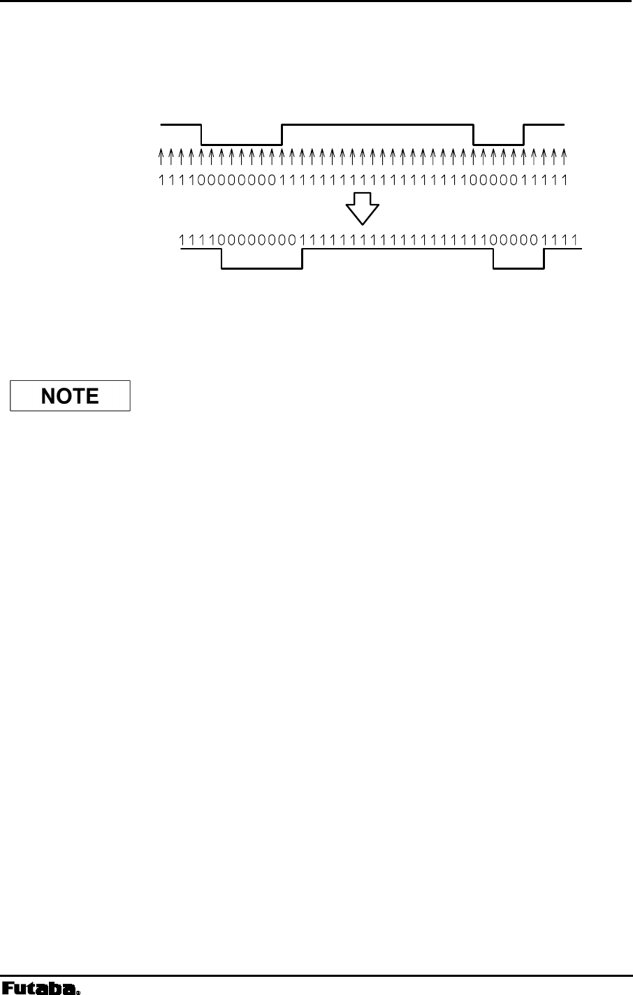
Page 128 FRH-SD07TU/TB Manual
Rev. 020510-01
The direct transmission mode features less delay time between the input of the transmit
data and the output of the receive data, i.e. about 500 us.
Figure 7–1: Transmission on Direct Transmission Mode
If the other end modem is the conventional type, such as FRH-
SD03TU, logic level is reverse that of FRH-SD07TU/TB. When FRH-
SD07TU/TB transmits [1], the conventional type modem receives [0].
Transmittin
g
Side
TxD In
p
ut
Sam
p
lin
g
Transmission Data
Receivin
g
Side
Receive Data
RxD Out
p
ut

Page 129
Futaba Corporation Rev. 020510-01
7.2.3 Memory Register Settings
In the direct transmission mode, set the following parameters. Keep other parameters as
being the factory default values.
REG03: Operation Mode Setting Default value: F0H
Set the operation mode to the direct transmission mode (01H).
REG06: Frequency Setting Default value: A0H
Set the frequency in operation. It is the same function as the basic function. Fixed
frequency mode is preferred to use in the direct transmission mode.
REG19: Communication Setting 2 [default value: 00H]
Only bit 6 is used. Use other bits than bit 6 as they are default values.
Bit 6: Diversity reception
• The same function as the basic function is valid.
REG20: RS-232C Setting 1 [default value: 05H]
・ Set the communication parameter to be used to accept command. The same function as
the basic function is valid.
・ Since TxD is sampled at 51.9 kHz, there is no relation between this setting and the actual
communication speed.
REG24: Special Mode Settings [default value: C0H]
Bit 7 – 6: reserved
• The direct transmission mode does not use this register. Keep the default value as it
is.
Bit 5: Delay time of transmission and reception (direct communication mode)
0 same delay time of the conventional type (13.5 ms, default value)
1 shorter delay time (3.5 ms)
Table 7–8: Setting of delay time of transmission and reception
in the direct communication mode

Page 130 FRH-SD07TU/TB Manual
Rev. 020510-01
• Set this parameter to the same value for both modems being communicated. Different
settings may cause undefined data output.
Bit 4: :
::
: DCD output (direct communication mode)
0 DCD output is the same of the conventional type (default value)
1 DCD output is the synchronous clock
Table 7–9: :Setting of DCD output in the direct communication mode
Bit 3 – 0: reserved
• The direct transmission mode does not use this register. Keep the default value as it
is.
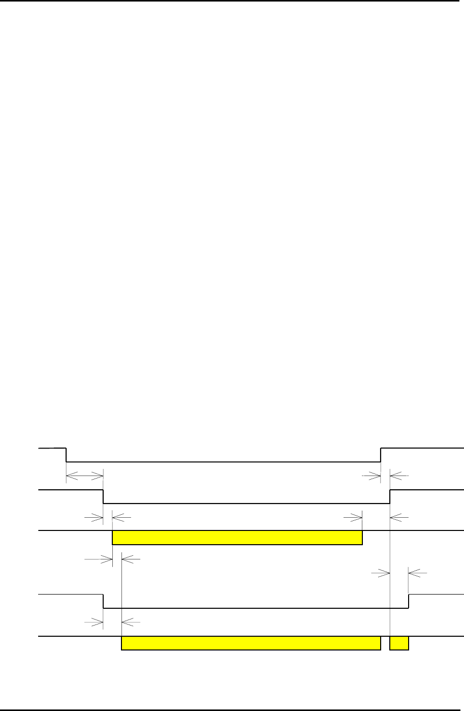
Page 131
Futaba Corporation Rev. 020510-01
7.2.4 Function of each terminal pin
Functions of the pin of the serial communication connector in the direct communication
mode are as listed below.
TxD (input) : Inputs the transmit data.
RxD (output) : Outputs the receive data.
RTS (input) : Controls the transmission and reception.
Sets to ON (Lo level) to make the modem to transmit.
CTS (output) : Indicates the modem is ready-to-transmit.
When RTS is ON (Lo level), the this pin goes ON (Lo level).
DCD (input) : Not used.
DCD (output) : Indicates that the modem is receiving valid data.
While data being received, this pin is ON (Lo level)
REG24 : Sets REG24:bit 4 to output the synchronous clock.
DTR (input) : Switched the transmission mode to/from the command accept
mode.
In the normal state, set to ON (Lo level). When issuing a command,
set to OFF (Hi level).
DSR (output) : Indicates that the modem can operate. When initializing completes,
after the input of RESET, this pin becomes ON (Lo level).
GND (input) : Ground signal
7.2.5 Timing
7.2.5.1 Timing chart of transmission and reception
Figure 7–2: Timing chart of transmission and reception
Typ 13.5ms (3.5ms)
Min 0us
Valid Data
Min 500us
Max 20us
Max 500us
Valid Data
Typ 500us
Min 500us
Note
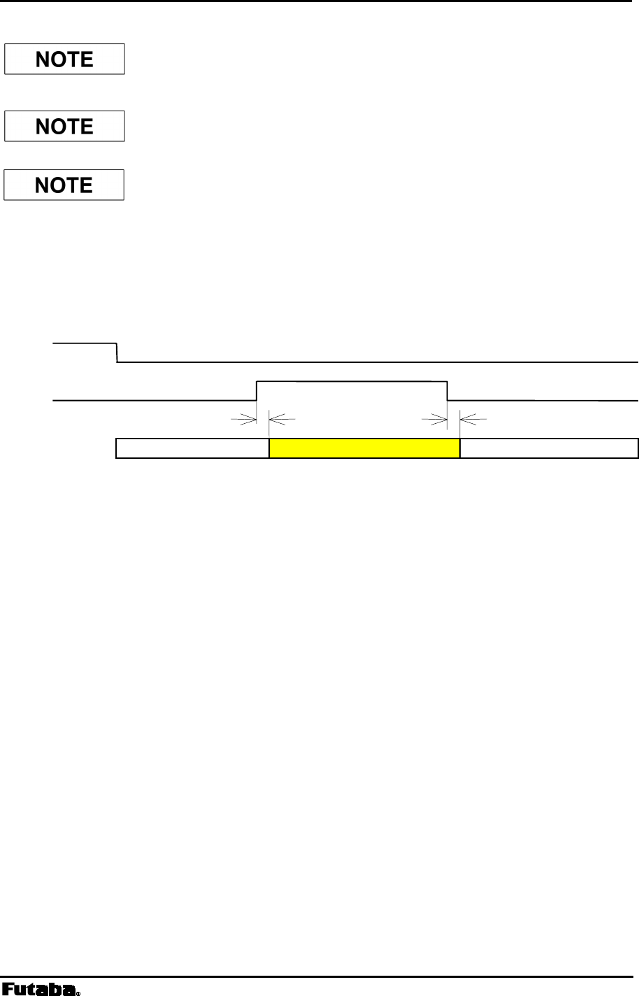
Page 132 FRH-SD07TU/TB Manual
Rev. 020510-01
In the state where DCD (output) is OFF (Hi level, i.e. receiving no
data), RxD is tied to OFF (High level).
DCD (output) may become ON (Lo level) due to incoming noise.
At this timing, undefined data may be output.
7.2.5.2 Timing chart of command accept
Figure 7–3: Timing chart of command accept
1. After transmitting the serial ID code, DSR becomes ON (Lo level) and the modem
becomes the state of ready-to-transmit (to-accept commands).
2. The serial ID code is transmitted after the decision that the channel is vacant by the
carrier sensing. When other modem is in transmission continuously on the same channel, the
serial ID code cannot be transmitted, and DSR pin does not go to ON (Lo level) until
channel goes vacant. In such a case, DCD (output) will stay ON (Lo level) state.
3. Since the transmission time of the serial ID code is short, it does not output as the receive
data.
4. Communication parameters such as the baud rate in the command accept state, that
follow the setting of REG20.
Tx/Rx Command Tx/Rx
Max 5ms Max 5ms
DSR
DTR
Status
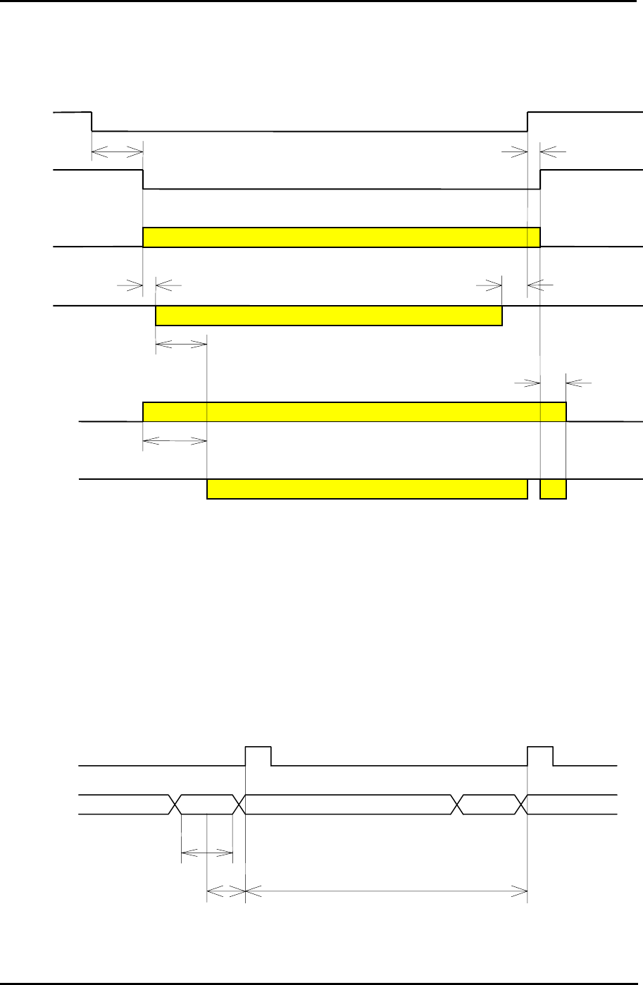
Page 133
Futaba Corporation Rev. 020510-01
7.2.5.3 Timing chart of synchronous clock
Figure 7–4: timing chart of synchronizing clock
1. On the sender side, after RTS goes to ON (Lo level), the transmission synchronous
clock outputs from DCD (output) at the same timing when CTS goes to ON (Lo level).
2. On the receiver side, the reception synchronous clock outputs from DCD (output) after
the modem received a valid data. The clock may output due to incoming noise.
Timing of the transmission synchronous clock and data
Figure 7–5: Timing of the transmission synchronous clock
Typ 13.5ms (3.5ms)
Min 0us
Valid Data
Min 500us
Max 20us
Transmit Clock
Valid Data
Receive Clock
Typ 500us
Min 500us
Max 500us
1.75us 19.25us
Ts=Th=0.1us(min)
RTS
CTS
DCD
(output)
TxD
DCD
(output)
RxD Spurious
Data
DCD
(output)
TxD

Page 134 FRH-SD07TU/TB Manual
Rev. 020510-01
TxD is sampled in 1.75 us before the rising edge of DCD (output). Detect the rising edge (or
falling edge) of DCD (output) to change the TxD level. H level duration of the clock in the
DCD output is 1.75 us.
Timing of the receive synchronous clock and data
Figure 7–6: Timing of the receive synchronous clock
RxD level changes synchronize with the rising edge of the DCD output. H level duration of
the clock in the DCD output is 875 ns.
19.25us
DCD
(output)
RxD

Page 135
Futaba Corporation Rev. 020510-01
7.3 ULTRA Mode
7.3.1 What is ULTRA mode
The ULTRA (Ultra Low Power Transient Radio Access) mode is the doze mode. The
modem operates in the intermittent receive state at the average current consumption of about
1/20 of the Active mode. The ULTRA mode is suitable for an application where the
modem does not originate transmission but only responds when it receives a call from other
station. Even current consumption is as low as 35 mA in the Active mode, the ULTRA
mode consumes only 2 mA (average). Therefore, dramatic extension of the operating
duration time is achieved in the battery powered operation. It is particularly effective for
portable applications where battery powered.
While the modem is in the ULTRA mode, the modem does not receive the normal packet,
it only receives the, special, wakeup request packet.
7.3.2 Operation in ULTRA mode
7.3.2.1 Memory register setup
For to use the ULTRA mode, set memory registers as follows.
REG25 : Set bit 7 to 1 (enable ULTRA mode)
REG25 : Set bit 6, when necessary
(1: with control frequency, 0:without control frequency)
REG06 : Set it, when necessary. (to set the frequency group)
The FRQ command setting gives no effect on the ULTRA mode operation. In the ULTRA
mode, REG06 is referenced for frequency operation.
For the control frequency, refer to the detailed description on p.141 CONTROL FREQUENCY.

Page 136 FRH-SD07TU/TB Manual
Rev. 020510-01
Transition to/from ULTRA mode
The DTR pin of the communication connector is used to transit to the ULTRA mode and
return to the Active mode. The logic level of the input pin of the FRH-SD07TU/TB is
described below. If the RS232 transceiver IC chip is connected, be noted that its logic level
inverts from the following description.
Figure 7–7: Transition to ULTRA mode
To transit to the ULTRA mode, set the DTR pin to Hi level. The modem detects the rising
edge of DTR pin and transits to the ULTRA mode. For returning to the Active mode, set
the DTR pin to the Lo level.
Since the DSR pin is used to monitor the ULTRA mode state, it can confirm the completion
of both transition to the ULTRA mode and returning to the Active mode.
It is possible to make the modem in the ULTRA mode return to the Active mode through
the radio link. Details are described in the following sections.
Request the ULTRA mode
Now in the ULTRA mode
DTR(input)
DSR(output)
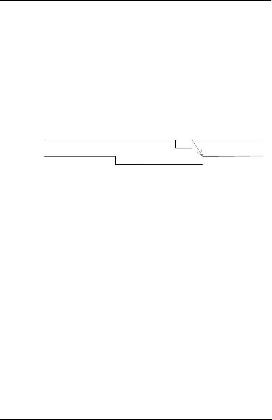
Page 137
Futaba Corporation Rev. 020510-01
7.3.2.2 Wakeup request packet
The wakeup request packet is a special packet to make the designated modem return to
the Active mode through the radio link.
In the ULTRA mode, the modem cannot receive normal packets but only receive the, special,
wakeup request packet. When receiving the wakeup request packet, the modem wakes
up and returns to Active mode in the following sequence. With upper layer application
software, the status of the modem can be monitored using DSR pin.
To transit to the ULTRA mode again, once set DTR pin to Lo level and again set to the Hi
level. At the rising edge of DTR, the modem transits to the ULTRA mode. While the
modem is wakeup state and make it to transit to the ULTRA mode, it should be performed
by the upper layer application software.
Figure 7–8: Wakeup
7.3.2.3 Operation in wakeup state
During the wakeup state (Active mode), the operation of the modem is identical to the
normal operation (i.e. the ULTRA mode is not set to the memory register), and all
commands are available for operation.
7.3.2.4 Operation in the ULTRA mode
The modem in the ULTRA mode intermittently operates at the period of 150 ms. For 8 ms
out of 150 ms, the modem is in activation state, and at the rest of the time it is in the
operation-full-stop state including clock signal.
The frequency, when the control frequency is used, it is fixed to the lowest of the group. On
the other hand, when the control frequency is not used, the frequency scans all frequency in
the group a dwell time of 150 ms/frequency.
7.3.2.5 Use of ULTRA mode together with shutdown state
The Shutdown mode and ULTRA mode can be utilized simultaneously. Force the
/SHUT pin (Pin 11 of the serial communication connector) to the Lo level completely
stops the operation of FRH-SD07TU/TB, consuming the least current. When longer time
for waking-up is affordable, the current consumption can be more reduced by
intermittently goes to the ULTRA mode from the Shutdown mode, e.g. at a cycle of 1
sec.
Receive wakeup packet Now in the Active mode
Request the ULTRA mode
Now in the ULTRA mode
DTR(input)
DSR
(
out
p
ut
)

Page 138 FRH-SD07TU/TB Manual
Rev. 020510-01
Since the wakeup request packet cannot be received when the modem is in the
Shutdown mode, it is necessary to issue the RLU command several times.
Even the modem is during the Shutdown mode, the DSR pin shows the state of the
ULTRA mode.

Page 139
Futaba Corporation Rev. 020510-01
7.3.3 Wakeup command
For these commands, refer to Chapter 6.
7.3.3.1 Direct wakeup : RLU command
Transmit Command
Use the RLU command to wakeup the modem in the ULTRA mode.
Command format: @RLU [Destination address]CR/LF
[Destination address]designates the destination (which is in the ULTRA mode) address
(the set value of REG00 of the receiving station in the ULTRA mode). Broadcasting
wakeup request packet (address 255) is also available. When the command is accepted,
“P1” response is output and the wakeup request packet is transmitted.
Wakeup ACK and response
The modem in the ULTRA mode, which received the wakeup request packet, always
checks destination address regardless of the status of REG19:bit 0. Accordingly, the modem
does not wakeup unless addresses correspond to each other.
When the modem receives wakeup request packet and being Active mode, its modem
returns ACK packet which inform the modem has been returning to Active mode, unless
the Broadcasting wakeup (destination address: 255) is designated.
The sender modem receives ACK from the destination station, it outputs “P0” response
following the “P1” response. In case of being unable to wakeup, ACK not received, or
wrong destination address, “N1” response will output which follows “P1” response.
When REG25:bit 7 is set to be the ULTRA mode enable, the modem returns ACK to the
wakeup request packet even the modem is in the wakeup state (Active mode). Therefore,
“P1” response will output after the “P0” response when the RLU command is issued for
the destination station in the Active mode.
Broadcast wakeup
When 255 is designated to [destination address] field, all receiver station does not return
ACK packet even these are being waken-up. So, as the command response, “P0” is output
always following “P1” output, after the defined number of retransmission count. In this
case, it is not assured whether the stations returns to the Active mode or not. It is
recommended to issue TXT command (to attempt communication) and such to the
destination station, for to confirm whether ACK packet is obtained or not from the
destination station.
Page 140 FRH-SD07TU/TB Manual
Rev. 020510-01
Figure 7–9: Wakeup using RLU command
7.3.3.2 Wakeup through repeater : RLR command
Transmit command
Use the RLR command to wakeup the modem in the ULTRA mode, through the repeater.
Command format : @RLR[repeater address] [destination address]CR/LF
[repeater address] designates the repeater to transmit the wakeup request.
[destination address] designate the station address (the set value of REG00) to be waken-up.
Broadcasting wakeup (address 255) is also available. On accepting this command, the
modem returns “P1” response and starts transmitting wakeup transmission request
packet to the repeater. And this packet makes the repeater to transmit the wakeup
request packet to the destination(s).
The transmission of wakeup request packet
The sender station transmits the wakeup transmission request to the repeater, its request
making the repeater to transmit the wakeup request packet to the destination(s). The
wakeup transmission request is repeated to transmit at the cycle of 200 ms by the
retransmission count designated by REG11 or RNO command.
At the repeater, the destination address checking function set by REG18:bit 0 is valid.
Accordingly, when the function is set to be valid, the repeater does not receive the wakeup
transmission request unless the repeater address matches.
When the repeater receives the wakeup transmission request, it transmits the wakeup
request packet to the destination station designated by [destination address] for 160 ms
duration. Though ACK packet is returned from the destination station, the repeater
ignores it and does not return ACK packet to the sender station. Therefore, even when the
single station is designated by the [destination address], the sender station cannot confirm
whether the destination station wakes-up or not. It is necessary to issue TXR command (to
attempt communication) and such to the destination station, for to confirm whether
response is obtained or not from the destination station.
Wake-u
p
Re
q
.
p
acket
ACK
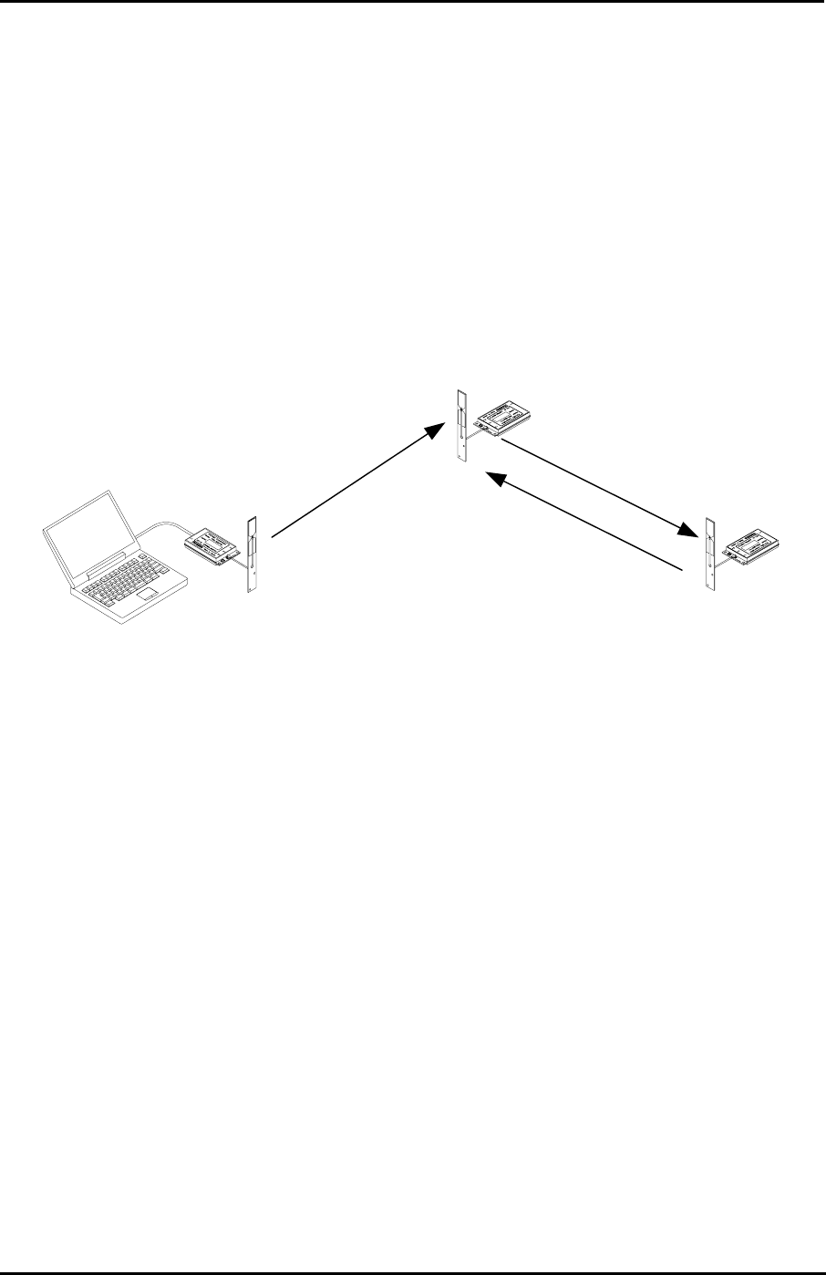
Page 141
Futaba Corporation Rev. 020510-01
Wakeup ACK and response
As described above, no wakeup ACK is returned from the repeater when the RLR
command is issued. To the RLR command, “N1” response is always output which
follows “P1” response except Broadcasting wakeup.
Note when the repeater is used
The utilization is the same as that of the normal repeater function. But, the frequency
setting of REG06, should be set the fixed frequency (Grouping Method H) mode when
the repeater is used. In this case, of course, the control frequency setting of REG25:bit 6
is invalid.
Figure 7–10: Wakeup using RLR command
7.3.4 Control frequency
7.3.4.1 What is the control frequency
When operating at frequencies in the group mode, the modem requires longer time to
establish the radio link connection because the modem in ULTRA mode is in receiving state
while changing frequencies. Therefore, to obtain high speed wakeup in the ULTRA mode,
the system can specify the control frequency. When the control frequency is designated,
the modem is always in the wait-to-receive state on the control frequency, which reduces
the time to receive the wakeup request packet.
The control frequency is set with REG25:bit 6 as follows.
REG25:6 1: control frequency designated 0: no control frequency designated
7.3.4.2 Control frequency allocation
The control frequency is allocated the lowest frequency of the frequency group. As being
the exclusive channel for wakeup, the control frequency cannot be used in the normal data
communication. This means that usable frequencies of the frequency group become less by
Demand packet for
Wake-u
p
p
acket Wake-u
p
p
acket
ACK

Page 142 FRH-SD07TU/TB Manual
Rev. 020510-01
one. The following explanation is based on the default setting of the frequency grouping
(REG06 = A0H).
Control frequency : Frequency No. 0
Communication frequency : Frequency Nos. 8, 16 (usable frequency for
communication becomes 2 from 3)
In the operation using the fixed frequency (Grouping Method H), only one frequency can
be used and the setting of the control frequency becomes invalid.
7.3.4.3 Extent of control frequency used
When a frequency group using more than 4 frequencies is set, the wakeup sequence speed
becomes faster if the control frequency is set. This is due to the timing to scan the
frequency between transmitter and receiver.
7.3.4.4 Transmission count of wakeup request packet
If multiple frequencies are used in the frequency group mode, the wakeup request
packet transmission count on a single frequency is as follows.
2 consecutive transmission using the control frequency (320 ms)
4 consecutive transmission count without using the control frequency (640 ms)
Using the control frequency ends transmission with 2 transmission counts. But without
using the control frequency, transmission continues for more counts by the number of
frequencies of the frequency group x 2 with scanning frequencies in the group. For example,
when 3 frequencies are used (Grouping Method F), transmission is performed up to 24
times (4 x 3 x 2 = 24) with scanning frequencies. Compared to the mode the control
frequency is used, the mode without the control frequency takes much more time to
transmit the wakeup request packet.
Be noted that the retransmission count set by REG11 is not applied in the case using
frequencies in the group mode.

Page 143
Futaba Corporation Rev. 020323-01
8
SECTION
8 APPENDIX
CONTENTS
8 APPENDIX.......................................................................................................143
8.1 INTERFACE ............................................................................................................................ 144
8.1.1 Pin Assignment............................................................................................................. 144
8.1.2 Interface Electrical Specification ..................................................................................145
8.1.3 Modem Initialization Time............................................................................................. 146
8.1.4 Electrical Static Discharge Remedy ............................................................................. 146
8.1.5 Line Noise Remedy ...................................................................................................... 146
8.1.6 Hardware Reset............................................................................................................ 146
8.2 CONVERSION CIRCUIT............................................................................................................ 147
8.2.1 RS-232C Level Converter ............................................................................................ 148
8.2.2 RS-422 Level Converter............................................................................................... 149
8.2.3 RS-485 Level Converter............................................................................................... 150
8.3 SPECIFICATION OF CONNECTORS............................................................................................ 150
8.4 AUXILIARY INTERFACE ............................................................................................................ 151
8.4.1 What is Auxiliary Interface............................................................................................ 151
8.4.2 Serial Communication Setting...................................................................................... 151
8.4.3 Output Format .............................................................................................................. 152
8.4.4 Output Timing............................................................................................................... 153
8.4.5 Output Status Data....................................................................................................... 154
8.4.6 Circuit Example Schematic to Receive Data................................................................ 155
8.5 OPERATION IMPORTANT NOTICE................................................................................... 157
8.5.1 Problem 1 (Spurious Packet Reception) ...................................................................... 158
8.5.2 Problem 2 (Transmission Command Error).................................................................. 159
8.6 Q & A ................................................................................................................................... 161
8.7 TROUBLESHOOTING ............................................................................................................... 163
8.8 SPECIFICATION ...................................................................................................................... 165
8.8.1 Radio Characteristics ...................................................................................................165
8.8.2 Communication Control................................................................................................ 165
8.8.3 Data Terminal Interface................................................................................................ 165
8.8.4 Power Supplying........................................................................................................... 165
8.8.5 Environmental............................................................................................................... 166
8.8.6 Miscellaneous............................................................................................................... 166
8.9 DIMENSIONS .......................................................................................................................... 167
8.9.1 FRH-SD07T.................................................................................................................. 167
8.9.2 Communication Cable .................................................................................................. 168
8.9.3 Flat Printed Antenna..................................................................................................... 168
8.10 GLOSSARY OF TERMS......................................................................................................... 169
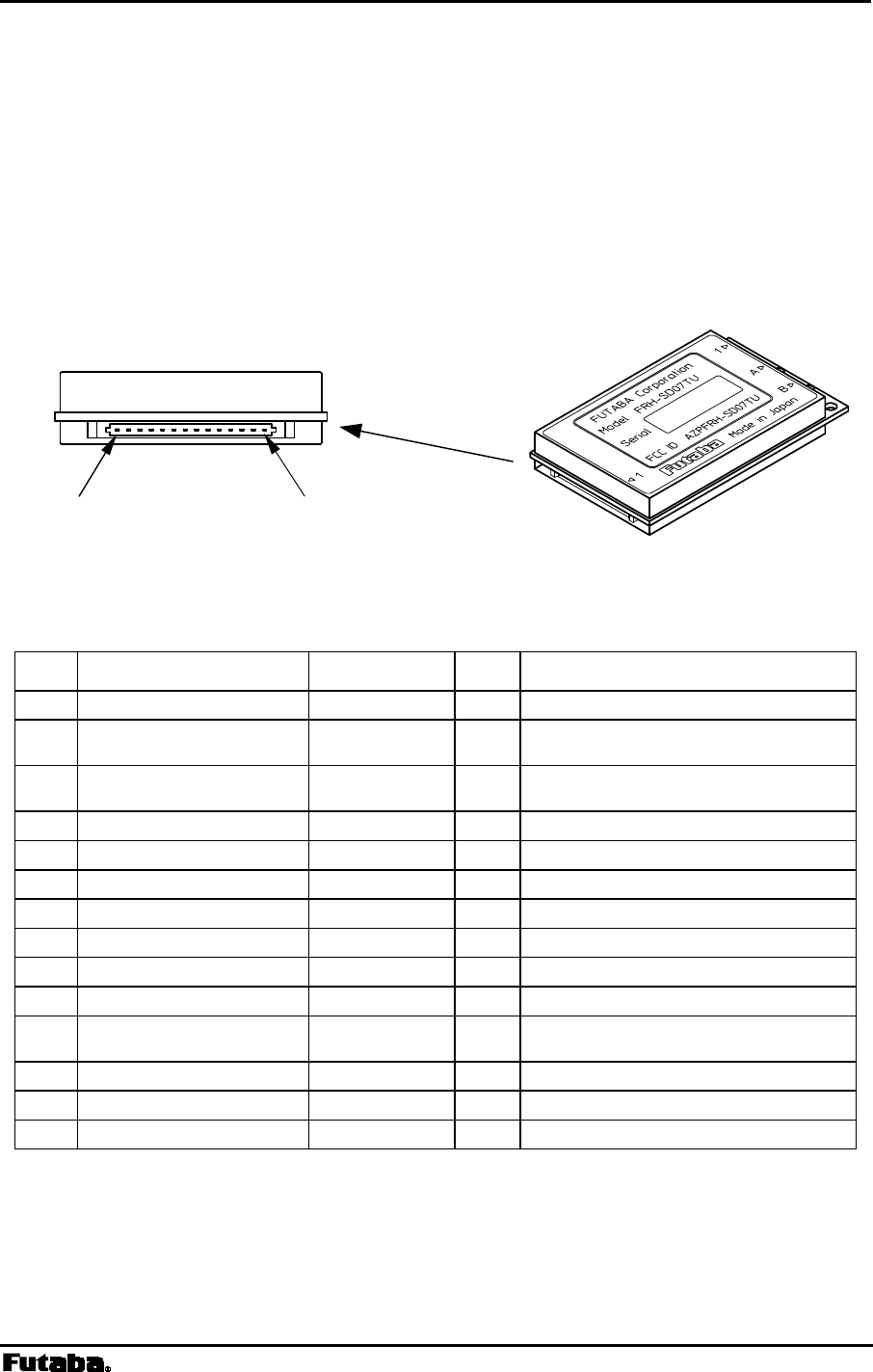
Page 144 FRH-SD07TU/TB Manual
Rev. 020510-01
8.1 Interface
8.1.1 Pin Assignment
The figure below shows the pin location of the serial communication connector, following
the DCE (Data Communication Equipment) specification.
Figure A–1: Serial Communication Connector Location
Pin Name Abbreviation I/O Function
1 Carrier Detect Out DCDO output carrier detect output
2 Receive Data RxD output
received data output (since modem
is DCE interface)
3 Transmit Data TxD input
transmit data input (since modem is
DCE interface)
4 Data Terminal Ready DTR input terminal ready
5 Signal Ground GND – signal ground
6 Data Set Ready DSR output modem ready
7 Request To Send RTS input receive stop/resume request
8 Clear To Send CTS output transmit stop/resume request
9 Carrier Detect In DCDI input ring indicator input
10 Power Supply VCC – 2.7V to 3.3V DC
11 Modem Shutdown /SHUT input
Shutdown mode. Do not leave this
pin OPEN
12 RS485 Enable 485ENB in/out RS485bus Tx Enable at 485mode
13 Load Default Parameter /DefParam input Load default parameter when low
14 Reserved Reserved – Reserved
Table A–1: Pin Descriptions
# 1 # 14

Page 145
Futaba Corporation Rev. 020323-01
1. The serial communication connector’s pin of the modem is defined as the DCE
specification, where transmission indicates input and reception indicates output.
2. Pin 12 is for tri-state control for RS485 driver (CMOS - RS485 level converter) which
will be externally mounted. When the power is turned on or reset, this pin is configured as
an input pin to read the operation mode in the interface. When it is pulled down, the
operation becomes the RS485 mode, and when it is pulled up (or leave open) the
operation becomes the RS232C mode. Since this pin becomes to configure the output
pin after reading the operation mode at the initialize state, never connect it directly to
VCC or GND. This pin is internally pulled up with 470 k ohm.
3. Pin 13 is internally pulled up with 100 k ohm.
4. The input pin tolerates 5 V input (5 V tolerant specification). When the user’s system is of
5 V, it is possible to interface with a such system.
5. Pin 11 can be used as the hardware reset. Since the input pin is at high impedance,
never fail to tie the input level.
6. It is no problem if Pins 12, 13 and 14 are leaved open.
7. Since the interface is CMOS structure circuit, it is recommended to take a remedy against
ESD problem (e.g. surge absorber; VRD series, made by Ishizuka Denki).
8.1.2 Interface Electrical Specification
(1) Supply voltage
Absolute maximum rating: -0.3 V to 4 V
Operation supply voltage: 2.7 V to 3.3 V
(2) Input circuit
Input circuit structure: CMOS input
Absolute maximum input voltage: +7V (input circuit is 5V tolerant)
Absolute maximum input voltage (-) -0.3V
Input voltage of signal ‘H’: 1 V minimum, 2.3 V maximum
Input voltage of signal ‘L’: 0.5 V minimum, 1.7 V maximum
* Hysteresis input (Schmidt) for the input circuit.
Input leakage current: +/-1uA maximum
(3) Output circuit
Output circuit structure: CMOS output
Output voltage of signal ‘H’: supply voltage -0.4 V min. (@1.8 mA)
Input voltage of signal ‘L’: 0.4 V max. (@1.8mA)
Absolute maximum current: 2 mA

Page 146 FRH-SD07TU/TB Manual
Rev. 020510-01
(4) signal specification
Mark: ‘H’ level
Space: ‘L’ level
8.1.3 Modem Initialization Time
The time required for the FRH-SD07TU/TB to be able to receive signals from the serial
interface (internal initialization time) is described below. After the initialization time
completes, feed the signals.
(1) The internal initialization time after the power supply is about 220 ms.
(2) The internal initialization time after the hardware reset (Shutdown mode) by
setting Pin 11 (/SHUT) to Lo level (force this pin with Lo level longer than 1ms), is
about 75 ms after returning its level to Hi.
8.1.4 Electrical Static Discharge Remedy
Since the interface of the FRH-SD07TU/TB is connected directly to the CMOS circuit, the
connection wiring is expected to be short wires. Therefore, the equipments for connection is
expected to be an embedded equipment where is mainly inside of the system.
When very long distance wire communication cable is used, RS422 or RS485 level
conversion is recommended.
Additionally, To secure more stable operation, it is recommended to take a remedy against
ESD problem (e.g. surge absorber; VRD series, made by Ishizuka Denki).
8.1.5 Connection to PC
Since the interface of the FRH-SD07TU/TB is connected directly to the CMOS circuit, the
signal level conversion circuit is required to connect it to the DTE (Data Terminal
Equipment) such as PC. For the level conversion circuit, refer to the following section. (The
power supply of 2.7 V to 3.3 V for the modem is also needed).
8.1.6 Line Noise Remedy
As being constructed with a highly sensitive RF analog circuit, the FRH-SD07TU/TB is
quite susceptible to noises. To secure more stable operation, serially provide the dumping
resistor at several 100 ohm to each signal line.
8.1.7 Shutdown Mode/Hardware Reset
Pin 11 of the serial communication connector can be used to the Shutdown mode or
hardware reset. Even when the Shutdown mode is not used, this pin should be controlled
by the terminal equipment to make the modem to reset.

Page 147
Futaba Corporation Rev. 020323-01
The modem does not get to system hung-up, however for an emergency, hardware reset
should be controlled to make it possible like a watch dog timer. When no response is
returned (modem hung-up) within the specified time due to an accidental error, a higher
reliable system can be configured.
8.1.8 Power Supply to the Modem
Since FRH-SD07TU/TB contains a very-high-frequency sensitive analog circuit, the modem
is susceptible to be affected the variation of the power source and noises from the terminal
equipment’s digital circuit. Therefore, when embedding the modem in the system, it is
necessary to supply power to the modem from the different (independent) power supply IC
chip other than those used in the digital circuits.
Also adding the line filter is important. Example is, use series 100 uH (must be enough low
ESR; Equivalent Series Register) inductor with shunted 100 uF capacitor. However, this
value is depend on user’s system environment. Please choice appropriate value for an
application.
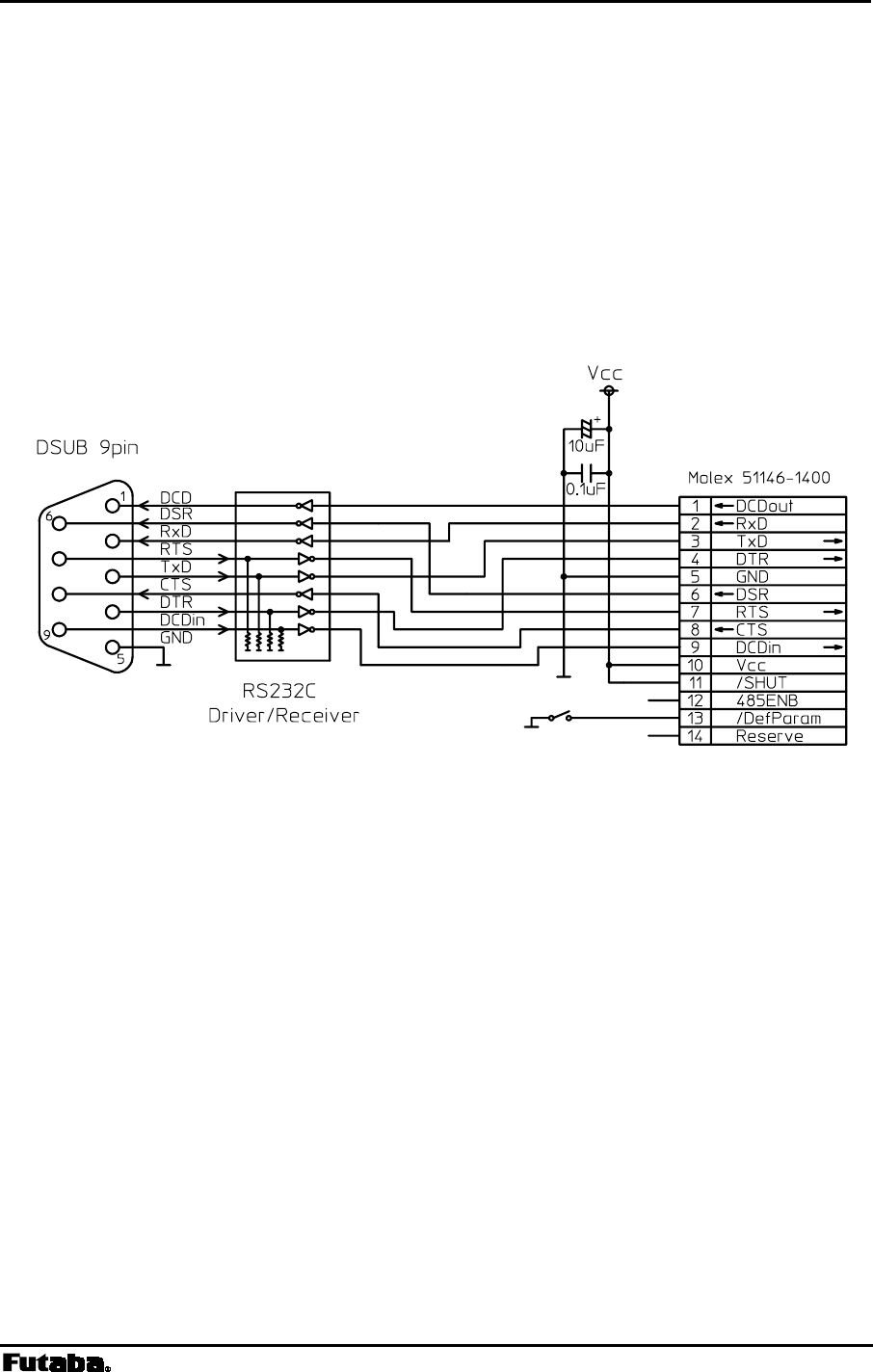
Page 148 FRH-SD07TU/TB Manual
Rev. 020510-01
8.2 Conversion Circuit
Examples of the level conversion circuit are shown as a reference, which is just for the
confirmation of system operation. This example does not guarantee the operation under
users’ actual operation environment.
8.2.1 RS-232C Level Converter
Wire the control line when necessary. Tie down unused input pin(s) to GND and leave the
485ENB pin open.
Figure B–1: RS-232C Level Conversion Circuit
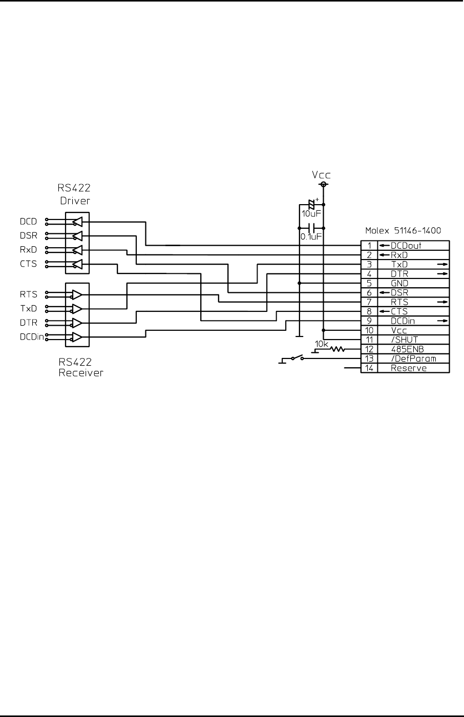
Page 149
Futaba Corporation Rev. 020323-01
8.2.2 RS422 Level Converter
Wire the output terminator (100 ohm) of the RS422 line driver, the input terminator (100
ohm) of the receiver, the input pull-up (1k ohm) and the input pull-down (1k ohm), when
necessary.
Provide a surge absorber (e.g. Z2012 made by Ishizuka Denshi) when long RS422 line is
used or there is much noisy environment, etc.
Figure B–2: RS422 Level Conversion Circuit
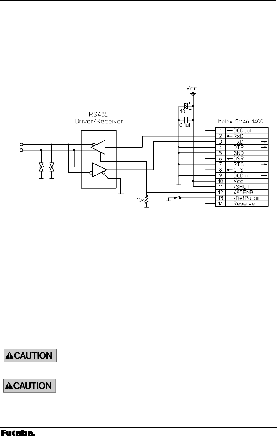
Page 150 FRH-SD07TU/TB Manual
Rev. 020510-01
8.2.3 RS485 Level Converter
Wire the terminator of the RS485 bus (100 ohm), the input pull-up (1k ohm) and the input
pull-down (1k ohm), when necessary.
When long RS485 line is used or there is much noise, provide the surge absorber (e.g. Z2012
made by Ishizuka Denshi) according to the situation.
Figure B–3: RS485 Level Conversion Circuit
8.3 Specification of the Connectors
(1) Serial Communication connector
Connector: MOLEX 53780-1490 (14 pins)
Mating Plug: MOLEX 51146-1400
(2) Antenna connector
RF connector: HIROSE U.FL-R-SMT
The antenna connector is guaranteed for 30 times of plugging in/out.
When plugging out the antenna connector, use the specially prepared
tool of E.FL-LP-N, provided by HIROSE (HIROSE Product No.
CL331-0441-9).

Page 151
Futaba Corporation Rev. 020323-01
8.4 Auxiliary Interface
8.4.1 What is Auxiliary Interface
A via-hole for a 5-pin connector for auxiliary functions is available, which you can use
according to the user’s requirement. Pin 3 to 5 can be used to monitor the internal status
using the 3-wire serial communication. Board-in connector which can be inserted into the
via-hole is listed below.
For electric specification, see p.145 INTERFACE ELECTRIC SPECIFICATION.
Connector : MOLEX 51022-0500 (5 pins) terminal used: 50061 (Board-in type)
Pin Name Function
1 /TxOn ‘L’ at transmission
2 Div/-Main
Selects the receiving antenna, ‘H’ on
the diversity side.
3 Status-Data
Outputs the serial data to monitor the
internal status.
4 Status-Clock
Outputs the serial clock to monitor
the internal status.
5 Status-Load
Output the serial load-enable to
monitor the internal status.
Table C–1: Auxiliary Interface Pin Descriptions
8.4.2 Serial Communication Setting
The clock rate of the serial signal output from the AUX interface can be changed with the
memory register, REG27:bit 5 and 4. The serial signal is not output by the default setting.
the status monitor circuit operates at the clock rate set by memory register and the serial-
clock of the AUX interface pin 4 is output at a half of the set rate.
Among monitoring status, there are high-speed one-shot signals. Which require high speed
serial-clock to sufficiently sample and output the status. Since higher clock rate results higher
current consumption, its rate can be controlled by the following parameters. To realize the
operation at lowest current consumption, use the default parameter which does not output
any serial clock.
REG 27
Bit 5 Bit 4 Setting
0 0 No clock output (default)
0 1 100 KHz
1 0 1.14 MHz
1 1 8 MHz
Table C–2: Clock rate of status monitor circuit

Page 152 FRH-SD07TU/TB Manual
Rev. 020510-01
8.4.3 Output Format
Signals are output in the following format.
One frame consists of 12 bits. The first 4 bits indicates which data frame is output from the
status monitor circuit (frame address), and the following 8 bits are the actual status signal.
Frames are repeatedly output from Address 0 to 4. Both the frame address and status signal
are the MSB first output.
As shown in the next paragraph of OUTPUT TIMING, these data are the clock synchronous
serial output, which is latched by rising edge of the LOAD signal at the end of each frame.
First bit Last bit
A3 A2 A1 A0 D7 D6 D5 D4 D3 D2 D1 D0
Frame Address (4bits) Status signal bits (8bits)
Figure C–1: Output Format
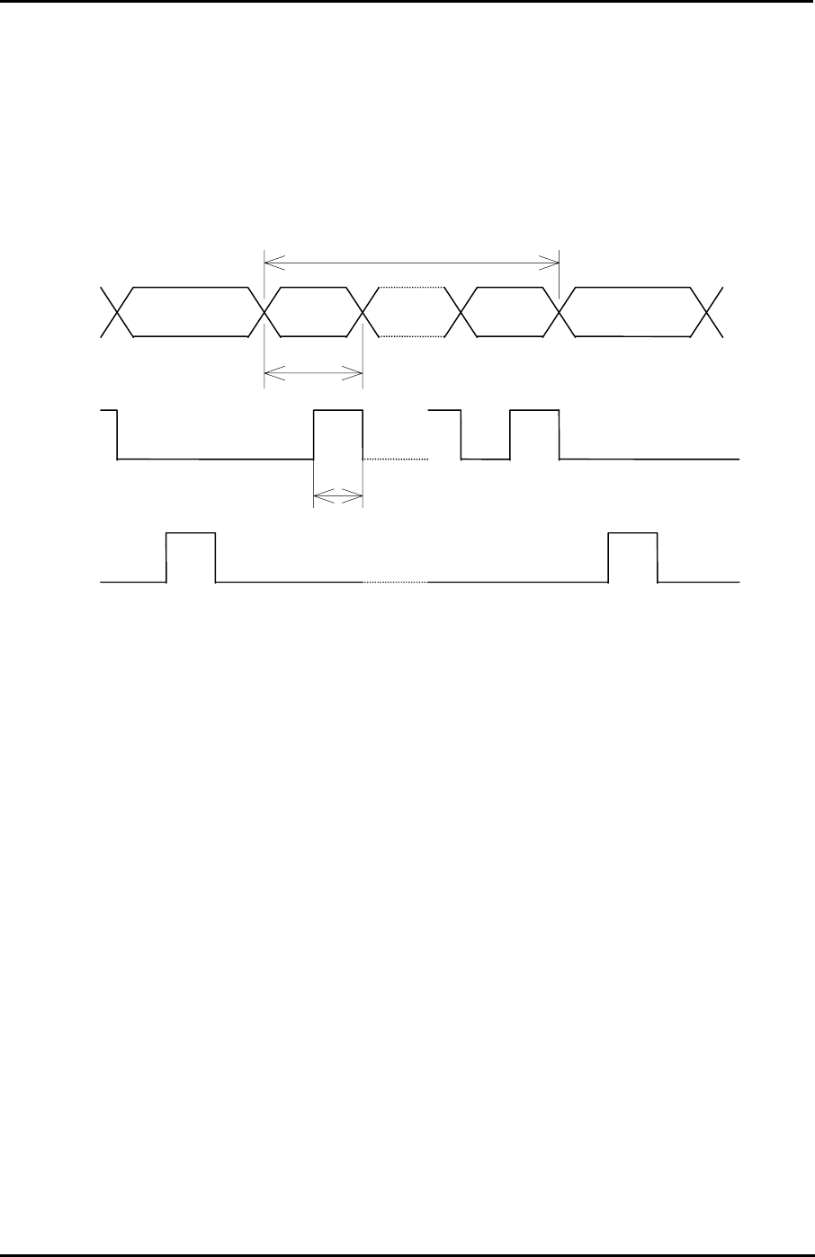
Page 153
Futaba Corporation Rev. 020323-01
8.4.4 Output Timing
Signals are output in the following timing, where Tc represents the clock rate set by REG27.
DATA line will be latched at the rising edge of CLOCK line, and 1 frame will be captured by
the rising edge of LOAD line.
Figure C–2: Output Timing
Not Valid Not Valid A3 D0
DATA
CLOCK
LOAD
2Tc
Tc
1 frame

Page 154 FRH-SD07TU/TB Manual
Rev. 020510-01
8.4.5 Output Status Data
The status data having the following contents are output.
Frame address
Status signal bit number
Signal name Contents Note
D7 CorrelationDetect Hi while correlation is detecting
D6 FrameSyncDetect Hi when frame-sync is detected,
Lo when correlation is lost
D5 TransparentLinkEstablished Not used
D4 OperateInUltraMode Hi while operating in ULTRA mode
D3 FreqChangeExecuting Hi while frequency is changing
D2 OperatingTransmissionCommand Hi while transmission command is executing
D1 TrxCtrlSeqIsPacketIdle Hi while no TX/RX operation is executing
0
D0 SystemErrorState Hi when system error occurred
D7 ReceiveSuccess Hi when receive success ONE
D6 ReceiveMyAckSuccess Hi when ACK receive success ONE
D5 Receive1packetError Hi when received but error occurred ONE
D4 DetectJabberPacket Hi while wakeup packet is receiving
D3 TransmissionSequenceResultCode(2)
D2 TransmissionSequenceResultCode(1)
D1 TransmissionSequenceResultCode(0)
Refer to note[1]
1
D0 0
D7 RxBufferFull Hi while the receive buffer is full
D6 RxBufferDataExist Hi while a data is existing in the receive buffer
D5 TxBufferFull Hi while the transmission buffer is full (mode 7)
D4 TxBufferDataExist Hi while operating in mode 7
D3 TxBufferOverflow Hi while the transmission buffer is overflowing
(mode 7)
D2 TxDataExistInTransAndFdaHdrless Hi while a data is existing in the transmission buffer
2
D1-0 0
D7 RxDteDataOutputEnable Hi while the serial port is enabled to output
D6 RadioDataReceiveEnable Hi while the radio is enabled to receive
D5 RsReceivedDataReceptionEnable Hi while the serial port is enabled to receive
D4 OperatingFreqChannelRegister(4)
D3 OperatingFreqChannelRegister(3)
D2 OperatingFreqChannelRegister(2)
D1 OperatingFreqChannelRegister(1)
3
D0 OperatingFreqChannelRegister(0)
Frequency channel number in operating (0∼23)
D7-5 0
D4 TopOperationState(4)
D3 TopOperationState(3)
D2 TopOperationState(2)
D1 TopOperationState(1)
4
D0 TopOperationState(0)
Reserved
Table C–3: Status Data
Note [1] Transmission Sequence Result Code (2-0)
Indicates the result of the transmit commands, e.g. TBR and TXT, which last
executed.
Bit2: ‘H’ when packet reaches to the repeater by the transmit commands passing
through the repeater.

Page 155
Futaba Corporation Rev. 020323-01
Bit1,0 are as shown below.
00 Packet reaches the receiver station.
01 No ACK is returned from the receiver station.
10 The receiver station is in the receive prohibited status.
11 The receiver station’s receive buffer is full.
“ONE” in the note indicates the one-shot signal of 20 usec.
8.4.6 Example Circuit Schematic to Receive internal Status
The following schematic shows a circuit which can receive the status serial signal.
Addresses to read-out are selected with the switches and the internal status are displayed with
LED.
The location of the connector in the following schematic is different
from that of the AUX interface of the FRH-SD07TU/TB. Be noted
that these pin numbers represent in the schematic are on the sample
circuit board (includes the power terminal).
Page 156 FRH-SD07TU/TB Manual
Rev. 020510-01
Figure C–3: Circuit Example

Page 157
Futaba Corporation Rev. 020323-01
8.5 Preventing Undesired Radio Connection
Futaba recommend user to set unique ID code to prevent unexpected interference (jamming)
between individual FRH systems working in the same area.
8.5.1 What is Interfere Problem
The “Interference” described here is
8.5.2 What is ID Code
ID code is 16 bit word set by REG04 and REG05. The FRH series radio transmits data with
code-scramble. Scramble data is made by the seed using this ID code. On the receiver side,
de-scramble is performed to restore original data using the same ID code (set on the receiver
side memory register) as the seed. Therefore, communication can not be established if both
sender and receiver modems do not set an identical ID code.
By setting this ID code, the interference problem can be decreased. But because of the FRH
modem employs carrier sense function, the function that the modem can not start
transmission during carrier is sensing (where other FRH modem station is in transmission) is
not affected by this ID code setting. Please do not misunderstand the purpose of this ID code
interference measure.
8.5.3 ID Code Setting
ID code can be defined by users. FRH-SD07TU/TB modem can set from 0000H to EFFFH
16 bit code, set by upper 8 bit to REG05 and lower 8 bit to REG04. This 16 bit value
should be choose as random as possible, to make good performance for this interference
problem.
However, still there has a possibility that the other system using same ID exists nearby, this
countermeasure can not to be perfect such a situation. Please understand this measure is for
to decrease the interference problem.
It is important to set “random” value for ID code. But if to obtain the value is difficult to
image, use below equations to define the ID code for you. Use the product serial number
which randomly selected from your FRH-SD07TU/TB modems you own.
Product serial number is 9 digits; divide these as [AA][BB][C][DDD][E].
REG05 = [{(AA MOD 10 ) + 11 } x BB] – 1
REG04 = DDD MOD 256
MOD is the modulo operator.
[Example]
If product serial number is 020809468, AA=2, BB=8, DDD=946. Therefore,
REG05 = [{(2 MOD 10) + 11} x 8] –1 = 103 -> 67H
REG06 = 946 MODE 256 = 178 -> B2H
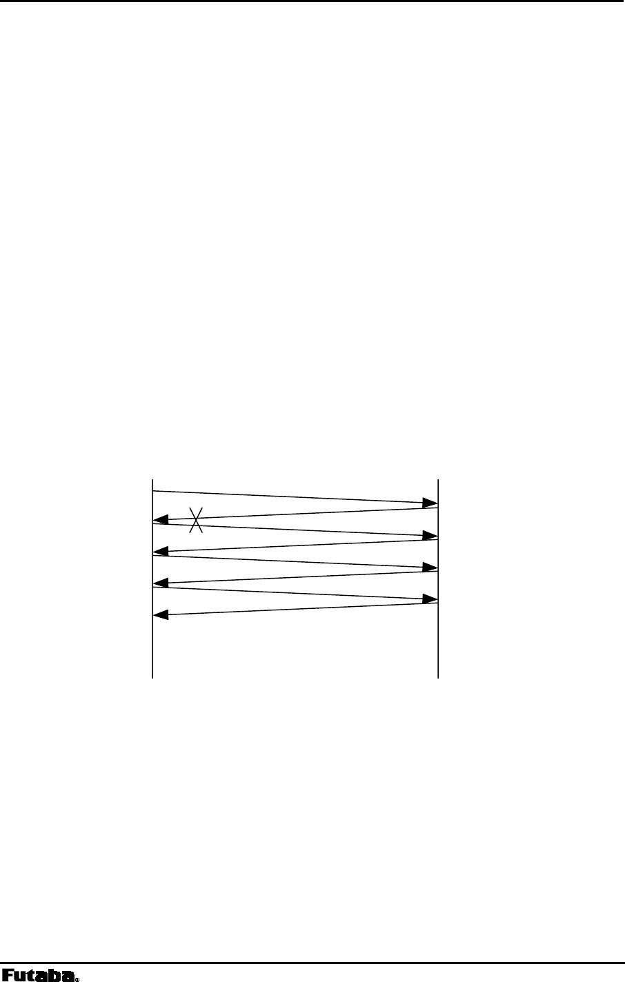
Page 158 FRH-SD07TU/TB Manual
Rev. 020510-01
8.6 OPERATION IMPORTANT NOTICE
Problems were found in the current version of FRH-SD07TU/TB (Version 1.00). Before
using this product, refer to the preventive measures described below.
8.6.1 Problem 1 (Spurious Packet Transmission)
8.6.1.1 Problem Description
At the final retransmission, when the sender modem transmits final packets due to transmit
error, ACK packet reception is started but its reception was failed, rarely the sender modem
which received ACK packet starts the repetitive “spurious packet” transmission. This
spurious packet format is same as that of ACK packet. In the receiver (remote) modem,
this spurious packet is recognized as the normal packet and starts receiving. And from
remote modem, it returns ACK to the sender modem. Again sender modem recognize this
ACK packet as a normal packet and returns ACK to the remote modem.
This sequence repeats until radio communication becomes error or next transmission
command (such as TXT or TBN) is issued. This problem tends to occurs in a
retransmission count is set to 0.
Local (address 123) Remote (address 210)
Last retransmission
Receive successfully
ACK receive error
RXT123
CRLF
RXT210
CRLF
RXT123
CRLF
RXT210
CRLF
RXT123
CRLF
RXT210 CRLF
Continue till receive error
When this problem occurs, both sender and remote modem repetitively output vacant packet
data (only header information) to the both terminal equipment.
[Example]
@TXT000AAA CR/LF
N1 CR/LF
RXT012 CR/LF (Spurious packet)
The probability of this problem occurs, it becomes large, when the retransmission count
(which set by RNO command or REG11) is set to small.
Data packet
Spurious packet
ACK
ACK
ACK
ACK
ACK
ACK

Page 159
Futaba Corporation Rev. 020323-01
8.6.1.2 Preventive countermeasure
If terminal equipment (or upper layer software) detects the spurious packet (header
information only), then discard this packet, and issue RST command or force /SHUT pin
(11pin) of the serial communication connector to low. The operation results modem to
reset. Once either side modem is being reset, this repetitive spurious packet stops and the
modem returns to normal operation mode.
8.6.2 Problem 2 (Transmission Command Error)
8.6.2.1 Its problem description
In the mode 3 and 5 (packet transmission mode and headerless packet transmission
mode), when the TBN, TBR, TXR and TXT commands (or headerless transmission
command) are issued, wrong data are output to the receiver modem’s terminal equipment
under the following condition.
As shown in the example, when the transmit command becomes error, the command error
response is returned.
[Example 1]
@TXT000AAAAAAAAA.............AAA
(excessive bytes due to the input maximum of 256 byte)
N0 CR/LF
[Example 2]
@TXT000ABCDE (becomes ‘time out’ at this point)
N0 CR/LF
If the next transmit command is issued at this stage and this command is successfully
accepted and performed, the wrong data (the contents of the last transmission-command
data) are send as the radio packet and output to the receiver end terminal equipment. The
contents of the “accepted, the next” transmission command data will not be transmitted.
(Refer the following example.)
@TXT000ABCDE (becomes ‘time out’ at this point)
N0 CR/LF
@TXT000KLMN CR/LF
P1 CR/LF
P0 CR/LF
@RXT000ABCD CR/LF (KLMN will be output.)

Page 160 FRH-SD07TU/TB Manual
Rev. 020510-01
8.6.2.2 Preventive countermeasure
In the normal case, these problems will not arise because packets are assembled by the upper
layer software in the micro processor of the user system. To secure the operation, take the
preventive measure as described below.
If the transmit command causes command error and “N0” response is returned, initialize
the transmit command with the RST command.
@TXT000ABCDE (becomes ‘time out’ at this point)
N0 CR/LF
@RST CR/LF
P0 CR/LF
This measure cannot be used in the headerless packet transmission mode (mode 5),
because no “N0” response is output.

Page 161
Futaba Corporation Rev. 020323-01
8.7 Q & A
Q: Can the modem be used in factories and other “radio unfriendly” environments?
A: Because electric discharge tools, inverters, and similar machines do not generate much
noise in the 2.4 GHz band, the modem can generally be used without problems in these
environments. Problematic noise sources are microwave ovens and other wireless
equipment that operate on the same frequencies as the modem. Install the modems as far
away as possible from RF noise sources. If possible, avoid using the interfering
equipment at the same time the modems will be in use.
Q: I want to use the modem for machine control. Are there any precautions that
require consideration?
A: In normal wireless communication, the modems check each received data packet for
errors and request packet retransmission if an error is detected. And also there occurs no
data error in the normal use. However, there is still a possibility of causing some troubles
which interfere communication when RF channel is used. It is necessary to design your
system to keep your machine out of such a communication trouble.
Q: Frequencies in the 2.4 GHz band are especially susceptible to multipath fading.
What are possible remedies for this?
A: Spatial and frequency diversity are two effective multipath remedies. By connecting the
receiving antenna to the diversity antenna terminal B for FRH-SD07TU/TB, diversity
reception is possible.
Because the modem can use 24 frequency channels, frequency diversity is also possible
by setting up an appropriate frequency grouping method and allowing the modem to
automatically search and select clear frequencies.
Q: My terminal software is set correctly, but I cannot successfully communicate over
the wire link. What’s wrong?
A: Several conditions can cause this. Check each of the following symptoms and correct as
described.
1. “N0” response is immediately returned when entering a command.
This indicates a command error and could be related to typing error or entering
commands in lower case. Make sure commands are entered using capital characters
and with syntax exactly as shown in the manual.
2. “N0” response is returned after about 5 seconds.
This can be caused by not sending a carriage return and line feed together as the
command terminator (CR/LF ).
This may also occur if the terminal software’s data length and modem’s data length
settings are different. Verify the settings and try again.

Page 162 FRH-SD07TU/TB Manual
Rev. 020510-01
3. Partial loss of characters on the terminal screen.
Check the terminal equipment communication speed and make sure that it is set to the
same setting as the modem.
Q: Multiple slave modems are being used in packet transmission mode, but ACK
packets are not being returned. Why?
A: If the destination address checking function is disabled (REG18:bit 0), the ACK
packet being returned from multiple slave modems are interfering with each other.
Enable the destination address check function using this memory register.
Q: The modem is being used in packet transmission mode and transmission failures are
being returned (response N1). How can I correct this?
A: Verify that the master and slave modems are using the same frequency grouping
method. The higher the number of frequencies per group, the more time it will take for
the modems to connect because transmit and receive modes must scan the frequencies in
the group until they align on one frequency. Try the following:
1. Increase the retransmission count (REG11).
2. Operate the modems in the fixed frequency mode (Grouping Method H).
If it is possible in the application (little or no RF interference), it is recommended that
the modems be operated in fixed frequency mode to shorten communication times.
Q: The transmitting modem outputs a transmission failed response (N1), but data was
received normally at the receiving modem. Why?
A: The ACK packet sent by the receiving modem was not be received by the transmitting
modem for some reason. Refer to the section in p.30 PRECAUTIONS IN PACKET
TRANSMISSION MODE.
Possible solutions are:
1. Increase the retransmission count (REG11).
2. Enable antenna diversity reception function.

Page 163
Futaba Corporation Rev. 020323-01
8.8 Troubleshooting
Refer to the following table for troubleshooting other problems.
Phenomenon Check Disposition
Is the Antenna connector connected
firmly? Connect the antenna connector
Is there any microwave oven or
other SS radio around the modem? Keep modem distant from
obstacle
Is the distance between two
modems too far? Reduce the distance till wireless
connection is made
Can’t establish wireless
connection
Is the frequency of all modems
matched together? Let REG06 the same setting
Is the communication cable
connected firmly? Connect the communication
cable
Can’t communicate with
terminal Are the communication settings (i.e.
baud rate, parity bit) matched
together?
Let the communication settings
match together
Table 8–1: Troubleshooting

Page 165
Futaba Corporation Rev. 020323-01
8.9 Specification
8.9.1 Radio Characteristics
Engineering standard FCC Part 15.247, ETS 300 440 approved (no user license required)
RF power output 5mW/MHz max.
Modulation Direct sequence spread spectrum
Communication scheme Single communication
Frequency band 2420.0 to 2479.0 MHz
Frequency channel 54 channels
(27 channels available for simultaneous communication in one area)
Channel management Fixed mode or group mode
Fixed mode: communication by fixing 1 arbitrary frequency from 54 freq.
Group mode: multi-access within a group of plural frequencies
Data barer rate 51.9 kbps
Oscillation PLL synthesizer
Antenna diversity 2 branch reception diversity
Service area In an indoor environment: 60m radius, depending on the environment
In an outdoor environment: more than 300m (line-of-sight)
RF connector Hirose U.FL-R-SMT
In/out of connector 30 times max. using E.FL-LP-N extractor (for exclusive use)
8.9.2 Communication Control
Radio link control Command control
Error checking CRC-CCITT (16 bit)
Error handling ARQ (Automatic Retransmission Request)
Multi-access function Connect on clearest channel from selected frequency group
8.9.3 Data Terminal Interface
Physical interface Molex 53780-1400 (14 pins)
Mating connector: 51146-1400
Interface specification Serial communication
Input CMOS level (5V tolerant with hysteresis)
Output CMOS level
Communication Full-duplex or half-duplex system
Synchronization Asynchronous
Transmit/receive buffer Approx. 3 k bytes in total
Baud rate 300 / 600 / 1200 / 2400 / 4800 / 9600 / 19200 / 38400 /50000 / 62500 / 83333
/ 100000 / 57600 / 115200 bps
Flow control Hardware flow
Data length 7 or 8 bit
Stop bit 1 or 2 bit
Parity Even, odd, or none
8.9.4 Power Supplying
Supply voltage 2.7 to 3.3Vdc
Current consumption 35 mA or less in the active mode
5 mA or less in the RF stop mode
2 mA in average in the ULTRA mode
70uA or less in the shutdown mode

Page 166 FRH-SD07TU/TB Manual
Rev. 020510-01
8.9.5 Environmental
Operating temperature -20 to +50 ℃
Storage temperature -20 to +60 ℃
Operating humidity 90%RH max. (no condensation)
Storage humidity 90%RH max. (no condensation)
Vibration resistance JIS-C-0040 (50m/s2, 10 to 150 Hz, 15 cycles
Shock resistance JIS-C-0041 (500m/s2)
(JIS specification is Japanese Industry Standard)
8.9.6 Miscellaneous
AUX terminal Outputs the transmission status, diversity status and internal status
applicable connector: MOLEX 51022-055 (5 pins), terminal used: 50061
Memory register Rewritable times: approx. 1 million times
Case Ni plated copper plate
Outer dimensions 30 (W)×50(D)×8(H)mm
Weight Aprox. 14g
† Operating distances depend on the conditions such as obstructions and electrical interference. Under ideal, line-of-sight
conditions, reliable operating distances greater than specified may be achieved. Optional, directional antennas can
significantly increase the operating range.
* Specifications and appearance are subject to change without prior notice.
Page 167
Futaba Corporation Rev. 020323-01
8.10 Dimensions
8.10.1 FRH-SD07TU/TB
Page 168 FRH-SD07TU/TB Manual
Rev. 020510-01
8.10.2 Communication Cable
8.10.3 Flat Printed Antenna

Page 169
Futaba Corporation Rev. 020323-01
8.11 Glossary of Terms
1:1, 1:n, n:m
Ratios indicating communication topology node architecture. The ratio 1:1 indicates a
system with only two nodes communicating with each other. The ratio 1:n indicates a
system with one “master” node communicating with a variable number of “slave”
nodes (also referred to as point-to-multipoint). The ratio n:m indicates a variable
number of nodes communicating with a variable number of other nodes.
ACK/NAK
In the packet transmission mode, a specific response is sent to the transmitting
modem to confirm the successful receipt of data, which is called ACK. In the
transmission through the repeater, the repeater sent a specific response to the
transmitting modem to convey that no ACK is returned from the destination modem
by the repeater, which is called NAK.
Antenna Diversity
A method commonly employed to improve the signal strength of received signals.
This method uses two independent antennas that receive signals differing in phase
and amplitude resulting a difference in the two antenna positions. Either the two
signals are summed or the strongest is accepted.
ARQ, or Automatic Retransmission Request
The method of checking transmitted data, used on virtually all high-speed data
communications systems. The sender encodes an error-detection field based on the
contents of the message and the receiver recalculates the field and compares it with
the one it received. If they match, an “ACK” (acknowledgement) is transmitted to the
sender. If they do not match, in some case, a “NAK” (negative acknowledgment) is
returned and the sender retransmits the message.
Asynchronous Communication
In this operation, the transmitting and receiving modems confirm the start and end of
1-byte data with the signal level (start bit and stop bit). As being simpler than the
synchronous system which requires to send the clock signal in addition to data, this
system is widely prevailing as the communication system of PCs. RS-232C interface
is originally the standard of the electric signal level, but actually it is called as the
asynchronous operation.
Bit
A contraction of the term “binary data”. A bit is the smallest unit of digital
information and is typically represented by a zero or one.
bps, or bits per second
The number of bits transferred per second.
Break Signal
One of a signal control signal. The data line (TxD/RxD) remains in the “Lo” state for
more than 1 byte (may be for several 100 ms). When data are sent in the

Page 170 FRH-SD07TU/TB Manual
Rev. 020510-01
asynchronous communication, a start bit and a stop bit are attached to separate a byte
data. For example, even if the data is “11111111”, there are the “Hi” state and the
“Lo” state for each byte. However, the break signal keeps the “Lo” state for more
than 1 byte (generally, for more than 3 bytes).
In the Modes 1 and 2 (in other FRH series employs), the break signal can be used as
the command header.
Byte
Originally from the expression “by eights” it represented a group of 8 bits. Today a
byte still represents a set of bits but of lengths specific to the computer or device
being used and can vary from 4 to 16 bits or more. Common byte lengths are from 7
to 12 bits.
Carrier sensing
In the packet transmission mode, frequencies are checked before transmission to
prevent the coincident transmission caused by multiple modems communicating in
the contention mode. This type of checking is called carrier sensing. As the
generally used term, carrier sensing means to check frequencies whether radio wave
exists or not. But with FRH-SD07TU/TB, carrier sensing function is enabled by the
correlation sensing, which is the specific feature of spread spectrum communication.
Command connection mode
This is one of the connection methods in the data transparent mode, the transmitting
modem designates the receiving address with the command to request connection.
After receiving the response from the receiving modem, the communication link is
established. Disconnection is also enabled by command. Communication switching
among multiple modems is possible.
Constant Connection Mode
In Constant Connection Mode, two FRH modems maintain a constant wireless link
whether or not regular data packets are being transmitted. Also see Automatic
Connection Mode.
CTS, or Clear To Send
In a standard RS-232C interface, this is an output for DTE devices and an input for
DCE devices. This signal is typically used to control flow from the DTE to the DCE
device.
Data Transparent Mode
Operation in which digital transmission between terminal equipments occurs without
the user or equipment being aware of any special intermediate processing or
equipment. This mode allows easy installation and compatibility of the FRH with
many systems and with no special hardware or software requirements. Data packets
are automatically assembled, transmitted and received without the need for specific
commands as are used in packet transmission mode. Also see p.18 PACKET
TRANSMISSION MODE.

Page 171
Futaba Corporation Rev. 020323-01
dB, or Decibel
A unit of measure for the power or strength of a signal. Given as the ratio of two
signal levels.
dBi
A decibel unit for measuring antenna gain. A unit of measurement of the gain relative
to an isotropic antenna, or one that radiates equal power in all directions.
dBm
Abbreviation for decibels above 1 mW, a unit for specifying input signal power – 1.0
mW across 600 ohms, or 0.775 V RMS (root mean square).
DCD, or Data Carrier Detect
In a standard RS-232C interface, this is an input for DTE devices and an output for
DCE devices. It indicates that the local DCE is receiving a carrier signal from the
remote DCE.
DCE, or Data Communications Equipment
A device that typically provides the interface between the DTE (Data Terminal
Equipment) and a network or another communication node. Examples of DCE
devices include modems, network interface cards, and routers.
Direct Sequence
A form of modulation (commonly used in spread spectrum communications) wherein
a code sequence is used to directly modulate a carrier, usually by phase-shift keying.
The FRH-SD07TU/TB is a Direct Sequence Spread Spectrum system. Also see
Frequency Hopping and Spread Spectrum.
DSR, or Data Set Ready
In a standard RS-232C interface, this is an output for DTE devices and an input for
DCE devices.
DTE, or Data Terminal Equipment
A PC, PLC, printer or other device that provides and accepts digital signals. Connects
to DCE devices (modem, network card, etc.).
DTR, or Data Terminal Ready
In a standard RS-232C interface, this is an output for DTE devices and an input for
DCE devices. It indicates that the DTE is powered on and ready to communicate. It
can also be used for hardware flow control.
Extended receiving function
In case of the contention-type communication in the packet transmission mode,
retransmission repeats when data are coincidentally transmitted between two or
several modems at the same time, resulting in the remarkable degradation of
response. The extended receiving function solves this problem. With the normal
receiving function, when the modem receives data during carrier sensing, it starts
repeating carrier sensing before the data is fully received. The data received during
carrier sensing is discarded. On the other hand, when the extended receiving function

Page 172 FRH-SD07TU/TB Manual
Rev. 020510-01
is enabled, the modem properly receives the data received during carrier sensing and
accepts to send the data to the terminal equipment. Then, the modem returns ACK
and resumes carrier sensing to continue transmission.
Fading
A gradual change in signal strength. Fade in refers to an increase in strength and fade
out refers to a decrease in signal strength.
Fade Margin
A margin of signal strength above the level required for communication under
“normal” conditions that will provide sufficient power for communication under
expected adverse conditions.
Flow Control
Hardware Flow Control:
The data flow is controlled by using RTS and CTS control lines of the RS-232C
interface. The FRH-SD07TU/TB outputs the received radio packet data when the
RTS input is ON and stops outputting the received radio packet data when the RTS
input is OFF. When the transmission buffer is near to overflow, the FRH-
SD07TU/TB switches the CTS output OFF and requests the terminal equipment to
stop data output. When the buffer becomes the receivable state, the FRH-
SD07TU/TB switches the CTS output ON to permit data output.
Software Flow Control:
One type of flow control of serial link, which controls data flow by transmitting and
receiving the specific control characters as data. Connection is very simple as no flow
control line is required. But be careful when you send or receive the binary data
because the control character cannot be distinguished from ordinary data.
The FRH-SD07TU/TB stops the output of the received radio packet data when it
receives the XOFF character (13H) and resumes the output of the received radio
packet data when it receives the XON character (11H). When the transmission buffer
is near to overflow, the FRH-SD07TU/TB outputs the XOFF character to request to
stop data input. When the buffer becomes the receivable state, the FRH-SD07T
outputs the XON character to receive the input of data.
Frequency group
The FRH-SD07TU/TB modem can use 24 different frequency channels. These 24
channels can be used independently or by grouping several frequencies and allowing
the FRH modem to automatically selecting a frequency from within the group. Mode
1 uses eight groups of three frequencies each. The frequency group configuration of
Modes 2, 3, and 4 can be changed using the associated memory registers. Separate
FRH systems can be set to different frequency groups and used in the same area
without interfering with each other.
Frequency Hopping
A spread spectrum technique in which the transmitter and receiver or transceivers in a
system change frequencies rapidly and in synchronization. In this way, the data signal

Page 173
Futaba Corporation Rev. 020323-01
is spread over a broad RF band through the continual frequency “hopping”. Also see
Direct Sequence and Spread Spectrum.
Full-Duplex
A type of two-way communication in which both stations can send and receive
signals or data at the same time. A telephone is an example of a full-duplex
communication device. Also see Half-Duplex.
Half-Duplex
A type of two-way communication in which both stations can send and receive
signals or data but not at the same time. When one unit is sending the other unit can
only receive. A CB radio is an example of a half-duplex communication device. The
FRH-SD07TU/TB essentially uses half-duplex transmission techniques but simulates
full-duplex communication by causing both units to switch very rapidly between
transmit and receive modes. This is also referred to as Time-Division-Duplex (TDD).
Also see Full-Duplex.
Headerless Packet Transmission Mode
The headerless packet transmission mode is a special mode of the packet transmission
mode, where data are directly input with no transmission command, as a header,
required in the packet transmission mode. Basically, this mode is the packet
transmission mode, therefore communication is possible with the modems in the
packet transmission mode. Due to its high data transparency, the application software
is quite simple or unnecessary. Suitable for the multi-terminal communication.
Multi-access
Automatic selection of an idle or clear FRH frequency from a defined group of
frequencies.
Broadcast/Multicast
This is a mode in which one FRH modem transmits the same message to multiple
receiving FRH modems simultaneously.
Multipath (Fading)
Multipath refers to the reception of the same RF signal from multiple paths such as
reception of the direct antenna-to-antenna signal and reception of a secondary signal
reflected from surrounding structures. This phenomena can cause signal fading due to
interference between the RF signals arriving from multiple paths.
Packet
A finite bundle of binary data assembled in a specific way for transmission. It
consists of the data to be transmitted and certain control information such as
destination and origination address, packet length, synchronizing bits, error detection
and correction bits, etc.
Packet Transmission Mode
The FRH-SD07TU/TB can use one of two primary modes: data transparent mode
and packet transmission mode. In packet transmission mode, fixed length segments of
data, consisting of information data and other control data, are assembled and

Page 174 FRH-SD07TU/TB Manual
Rev. 020510-01
transmitted as a single unit or packet of data. Each transmission is controlled with
explicit transmit commands.
Polling- and Contention-type Communication
The polling is a type of communication, where the slave station can communicate
only when it receives the polling request of message data from the master station.
The contention is another type of communication, where any station may transmit if
the channel is free; if the channel is in use, the queue of contention request may be
maintained in the predetermined sequence.
Repeater
Equipment that receives weak signals and retransmits the same data in stronger
signals. Used to extend range or overcome obstacles and horizon constraints in RF
communication systems. An FRH-SD07TU/TB can be configured as a repeater to
effectively double the normal range between two FRH modems or to allow
communication around obstacles that would otherwise block line-of-sight
transmission.
Response
One of the values to express the communication speed, indicating the time delay
required by the transmitted data to reach the receiving modem. The smaller the value
becomes, the quicker the response requiring the machine control application.
However, it must be noted that the response is not always quick when the throughput
is large.
RS-232C
Also referred to as RS-232C and currently EIA-232E, RS-232C is a set of standards
specifying electrical, functional and mechanical interfaces for communicating
between computers, terminal equipments and modems (DTE and DCE).
RTS, or Request To Send
In the standard RS-232C interface, this is an output for DTE devices and an input for
DCE devices. This signal is typically used to control flow from the DCE to the DTE
device.
Spread Spectrum
A modulation technique that spreads data over an RF bandwidth wider than would
normally be required by the content of the original data stream. This technique
provides high levels of communication reliability and security. In the modulation
system generally used for radio, the bandwidth is about the same as the frequency of
the data signal. But in the spread spectrum system, the bandwidth is much wider than
the frequency of the data signal (tens to several thousands times), in other word, the
spectrum of the data signal can be spread in a broad range, thus this system is called
the spread spectrum (SS).
i.e. Frequency Hopping and Direct Sequence. See also Direct Sequence and
Frequency Hopping.

Page 175
Futaba Corporation Rev. 020323-01
There are two main types of spread spectrum techniques: one is called the direct
sequence (DS) system where the modulated data signal is modulated to further spread,
another is the frequency hopping (FH) where the frequency of the modulated data
signal is changed rapidly. The FRH-SD07T modem uses the direct sequence system.
Direct Sequence (DS): A form of modulation (commonly used in spread spectrum
communications) wherein a code sequence is used to directly modulate a carrier,
usually by phase-shift keying (PSK). The FRH-SD07TU/TB is a Direct Sequence
Spread Spectrum system. Also see Frequency Hopping and Spread Spectrum.
Frequency Hopping (FH): A spread spectrum technique in which the transmitter and
receiver or transceivers in a system change frequencies rapidly and in
synchronization. In this way, the data signal is spread over a broad RF band through
the continual frequency “hopping”.
TDD, or Time-Division-Duplex
See Half-Duplex.
Throughput
One of the values indicating the capacity of the communication link; amount of data
available for transmission or receiving per unit time. In the transmission of large
amount of data, with the increase of data, the transmission time becomes shorter.
Since the FRH modem transmits data in packet, the throughput varies according to
the ratio of data contained in a packet.

Rev. 020510-01
Futaba Corporation
Radio Control Equipment Group
1080 Yabutsuka Chosei
Chiba, 299-4395 JAPAN
Tel: +81 (475) 32-6173, Fax: +81(475) 32-6179
Internet: www.futaba.co.jp
In the United States
Futaba Corporation of America
Industrial Radio Control Department
1605 Penny Lane
Schaumburg, IL 60173
Tel: (847) 884-1444, Fax: (847) 884-1635
Internet: www.futaba.com
In the Europe
Pending.