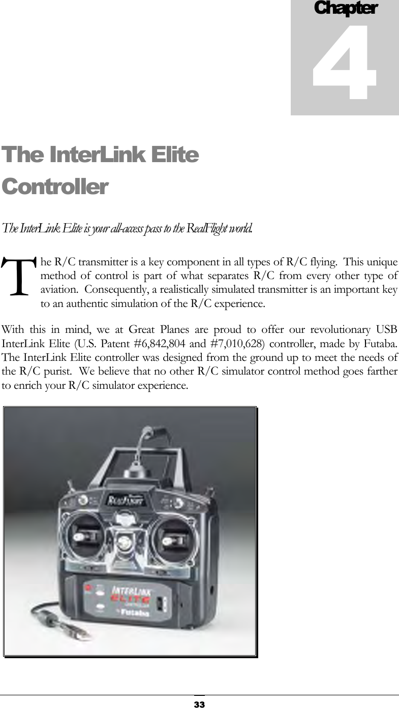
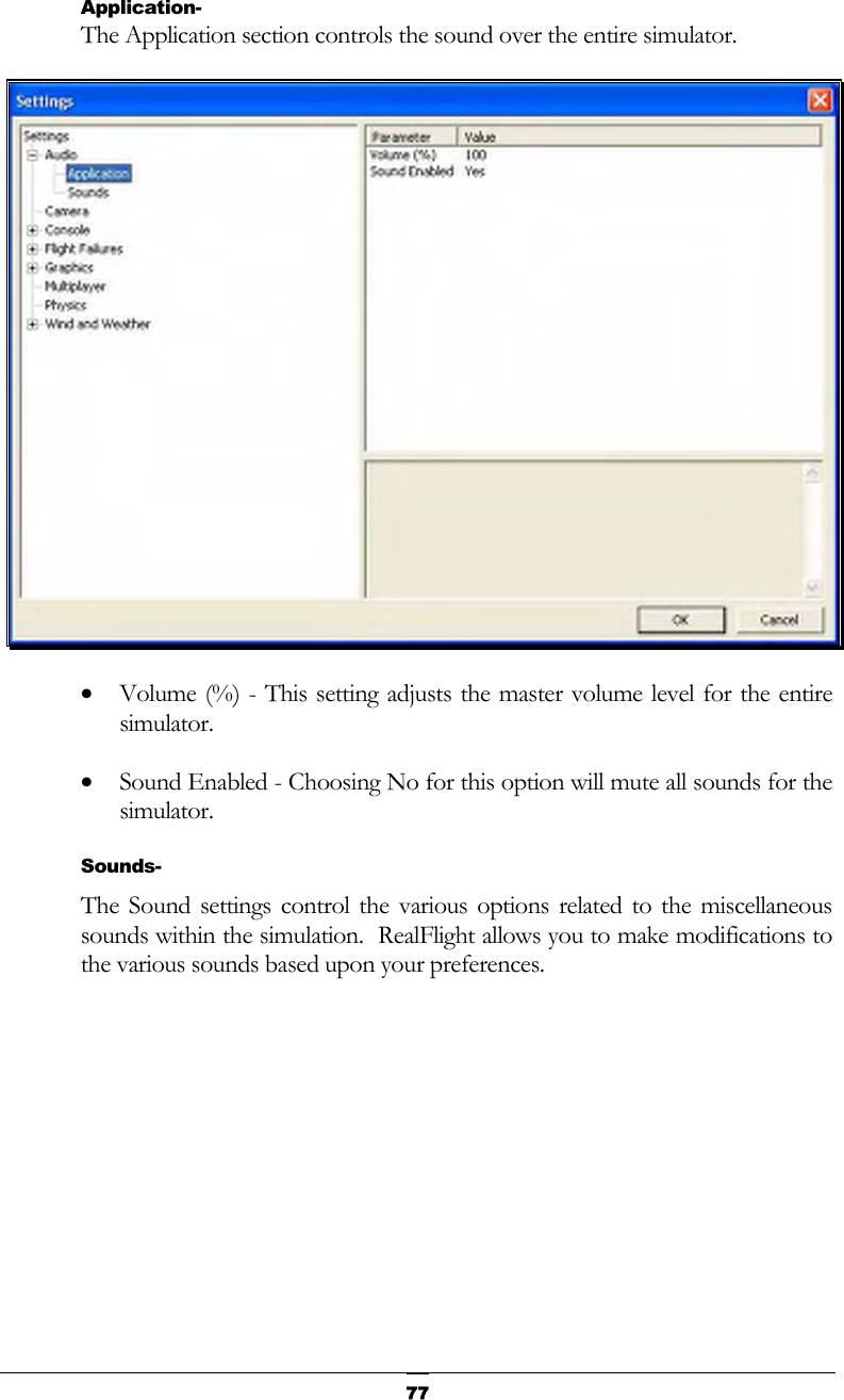
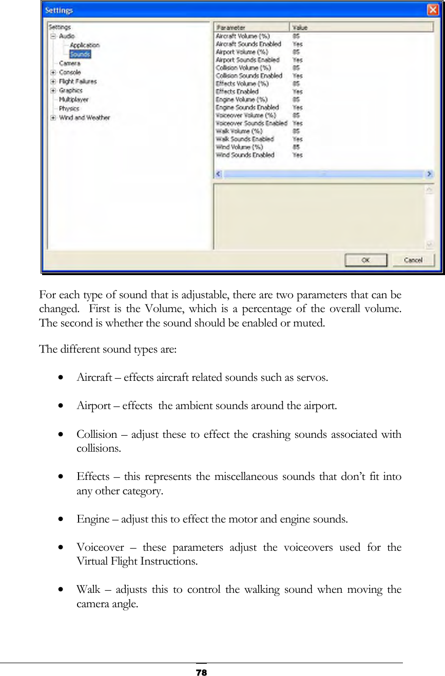
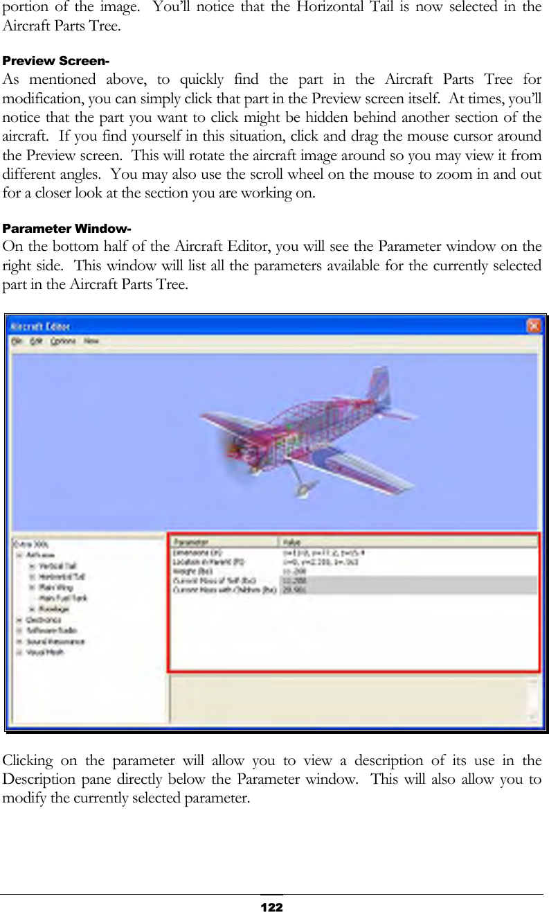
Futaba FS006H USB Flight Controller User Manual
Futaba Corporation USB Flight Controller
UserManual.wiki
>
Futaba
>
FS006H User Manual
>
User Manual I
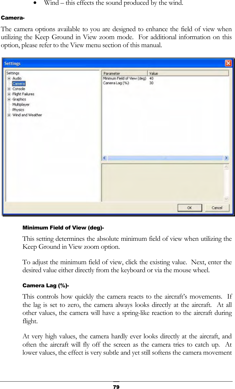
Contents
1.
User Manual I
2.
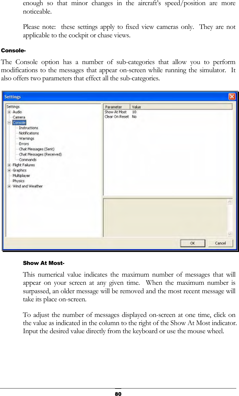
User Manual II
User Manual I
Navigation menu
Upload a User Manual
Namespaces
Wiki Guide
HTML
PDF
Info
Views
User Manual
Discussion / Help
Navigation


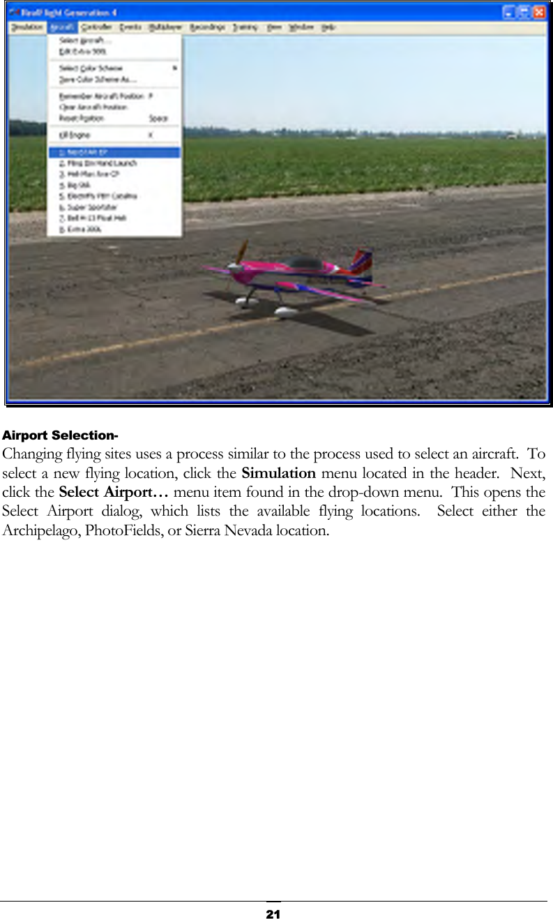
![20Each aircraft available in G4 is listed along the left-hand side. The icon next to each name differs depending on whether the model is an airplane or a helicopter. To select an aircraft from the list, click on the desired aircraft. The selected model will now appear in the ReadySelect™ preview box. Additionally, an aircraft description and information data will appear in the aircraft information pane, which appears just below the ReadySelect preview window. When you are satisfied with your selection, click OK to return to the simulator using the new aircraft selection. Complete information pertaining to the Select Aircraft… menu item is available in a later chapter of this manual. Alternatively, you may use the InterLink Elite controller to change aircraft selections. Simply press the Menu/Select button located on the front of the InterLink Elite controller. This will bring forth the QuickSelect tabs on the left side of the computer screen and the aircraft selection tab, represented as an airplane icon, should be the highlighted tab. Press the Menu/Select button once again to bring up the Aircraft Selection dialog box. Move the Data Lever, found on the lower right side of the InterLink Elite controller, up or down to view the available aircraft. The [+] (plus) indicates that there is another expansion level (selection) available to you, press the Menu/Select button to access the items located within this folder. To select an aircraft, simply highlight the name and press the Menu/Select button. You will return to the simulation using the newly selected aircraft. If you wish to exit the Aircraft Selection screen without making any changes, simply press the Reset button on the InterLink Elite. Aircraft Most Recently Used List (MRU)- If you have selected alternative aircraft previously, you will note that these aircraft appear on a list in the Aircraft menu, as shown below. This list is at the very bottom of the menu. This list is commonly referred to as a Most Recently Used, or MRU list. It is limited to the eight most recently used aircraft. If you wish to fly one of the aircraft from this list, simply click on the name of the aircraft in the MRU list.](https://usermanual.wiki/Futaba/FS006H.User-Manual-I/User-Guide-859426-Page-25.png)
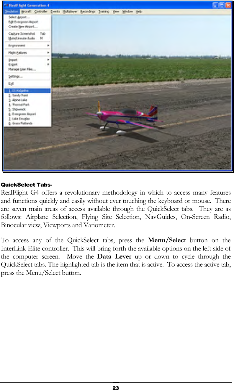
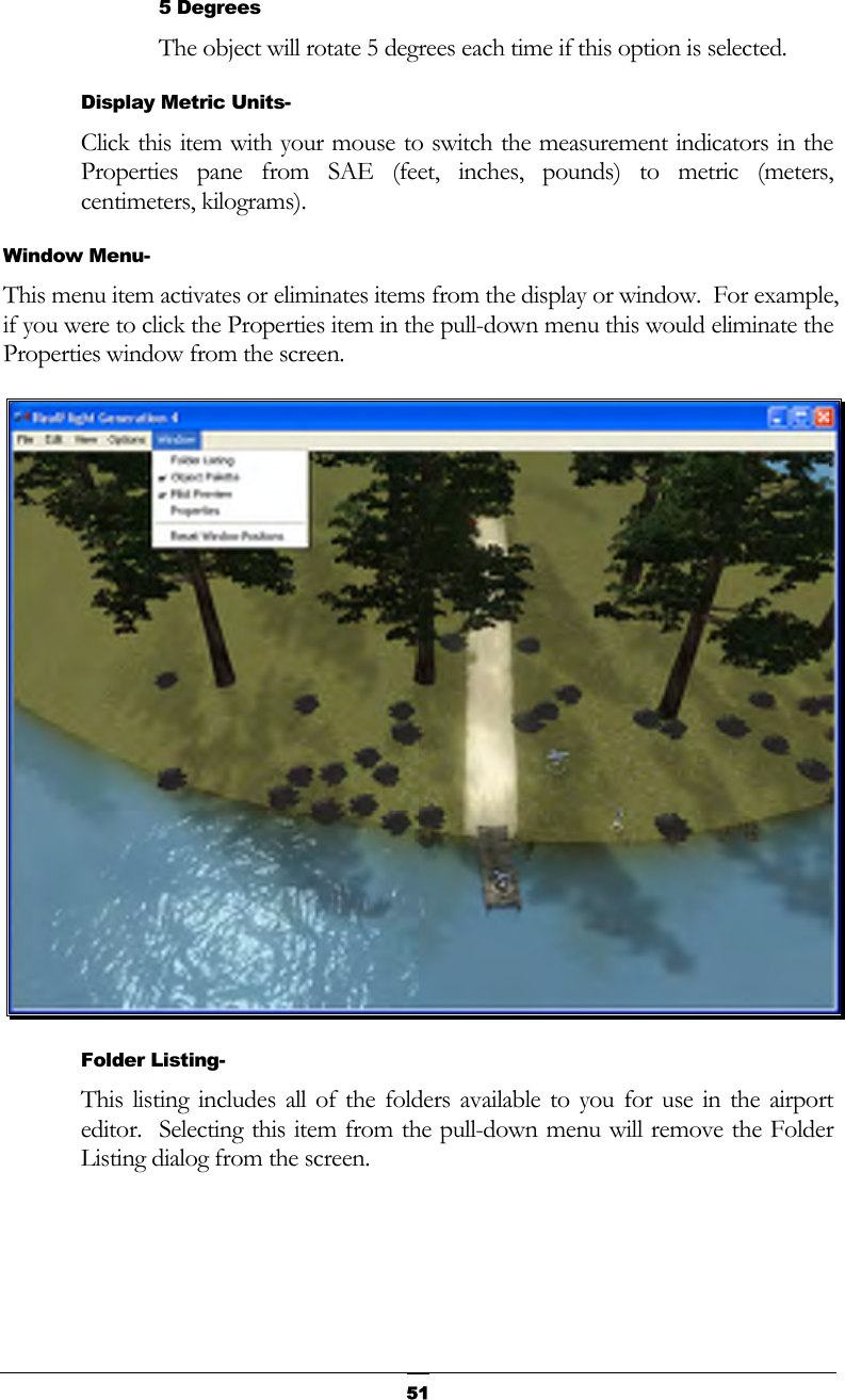
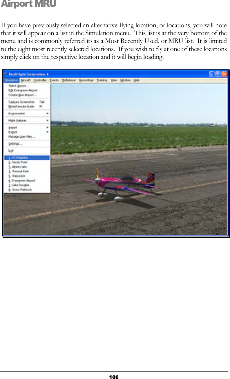
![22 Each airport is preceded with a [+] (plus) and an icon. The [+] (plus) indicates that another expansion level (selection) is available to you. To access the complete list of airports for a respective location, either click the [+] (plus) or double-click on the desired airport. For example, clicking the [+] (plus) on the PhotoField folder reveals all of the PhotoField flying sites available to you. To select an airport from the list, click on the desired airport. The selected airport will now appear in the preview box. Additionally, an airport description and informational data will appear in the information pane, which appears just below the preview window. When you are satisfied with your selection, click OK to return to the simulator using the new airport selection. Navigating the Airport Selection menu using the QuickSelect feature is almost identical to the process mentioned above for selecting an alternative aircraft. Only this time, you will select the airport selection menu, which is represented by a runway icon. With the QuickSelect tabs visible on the computer screen, move the Data Lever down one time. This should highlight the runway icon. Press the Menu/Select button to bring forth the available flying sites. Using the same method, as described previously for aircraft, select the new airport and press the Menu/Select button to return to the simulation using this new flying site. Airport Most Recently Used List (MRU)- If you have previously selected an alternative flying location, it will appear on a list in the Simulation menu. This list is at the very bottom of the menu and is commonly referred to as a Most Recently Used, or MRU list. It is limited to the eight most recently selected locations. If you wish to fly at one of these locations simply click on the respective location in the MRU list to load it into the simulation.](https://usermanual.wiki/Futaba/FS006H.User-Manual-I/User-Guide-859426-Page-27.png)
![24 For additional information on how to use the QuickSelect tabs, please refer to the information contained in the section entitled QuickSelect- on page 35. Some Common Tasks- • The easiest method of resetting your aircraft to its original takeoff position is to press the reset button located on the front of the InterLink Elite controller. Alternatively, you can reset the aircraft by pressing the space bar on the keyboard, or by selecting the Reset Position menu item, which is located in the Aircraft menu. • If your aircraft is equipped with smoke, the two-position switch located on the right side of your InterLink Elite controller will generally be utilized to activate this feature. • To magnify the view or zoom in on an aircraft, press the [+] (plus) key on the number pad of the keyboard. Alternatively, you may use menu commands to zoom in. To do so, click on the View menu and then click on the Zoom In menu item. Each time the [+] (plus) key or the Zoom In menu item are pressed or selected, the view will increase incrementally. • To reduce the magnification, or zoom out of the current view press the [–] (minus) key on the number pad of the keyboard. Alternatively, you may use menu commands to zoom out. To do so, click on the View menu and then click](https://usermanual.wiki/Futaba/FS006H.User-Manual-I/User-Guide-859426-Page-29.png)
![25on the Zoom Out menu item. Every time you press [-] (minus) key or select and press the Zoom Out menu item, the view will decrease incrementally. • To reset the view to the default magnification, press the Backspace on the keyboard. Creating a Viewport- RealFlight allows you to create an additional picture-in-picture viewport. Once you create a new viewport, you may resize or reposition it by dragging with the mouse. You can also fully adjust all of the viewport’s properties independently of the main window. The viewports may be utilized for a variety of applications, such as changing the viewing perspective of your simulation. To create a new viewport, click the Window menu title followed by the Create New View menu item. Alternatively, you may also press the ‘4’ key on the keyboard to create an additional viewport. To change the vantage point within the viewport, press the ‘C’ key on the keyboard. The ‘C’ toggles through the various camera modes; the first of which is the cockpit or pilot’s perspective. The second is chase view, and the last mode is the fixed viewpoint, or what you would see if you were standing at the side of the runway. Please note: depending upon the flying site selected, some of these viewing options may not be applicable.](https://usermanual.wiki/Futaba/FS006H.User-Manual-I/User-Guide-859426-Page-30.png)
![26The Window chapter of this manual contains a thorough explanation of the viewports and the viewport options. Using Gadgets- The RealFlight G4 software includes several gadgets that may be displayed in the main window when running the software. A gadget is an on-screen display that provides helpful information or allows you to access to a variety of RealFlight features and functions. For example, the NavGuides gadget displays continuously updated information relating to your aircraft’s altitude, airspeed, directional heading, and other flight parameters. To display the NavGuides gadget, click the Window menu title followed by the Gadgets menu item. Next, select the NavGuides gadget located in the drop-down menu. You may also access the NavGuides gadget by pressing the numerical ‘1’ key on your keyboard. Alternatively, you may activate the NavGuides gadget through the QuickSelect tabs. To do so, press the Menu/Select button on the InterLink Elite controller. Next, move the Data Lever downward twice. Finally, press the Mode/Select button to activate the NavGuides. When you select NavGuides, you should see the NavGuides gadget appear on your screen: As discussed previously, you can customize the gadgets for personal preference. For complete information on how to do so, please refer to the chapter pertaining to the Window menu options. Virtual Flight Instruction- RealFlight G4 includes a variety of basic, intermediate and advanced pre-recorded maneuver lessons for helicopter and airplane pilots. A professional, award-winning R/C pilot talks you through every facet of the maneuver. You can use the Virtual Flight Instruction to learn new maneuvers as well as to perfect those maneuvers that you already know. To activate the pre-recorded maneuvers, click on the Training menu followed by the Virtual Flight Instruction… menu item. Alternatively, press the ‘V’ key on your computer’s keyboard. Either method brings forth two options: airplane and helicopter, each proceeded by a [+] (plus) symbol. If you wish to practice an airplane-](https://usermanual.wiki/Futaba/FS006H.User-Manual-I/User-Guide-859426-Page-31.png)
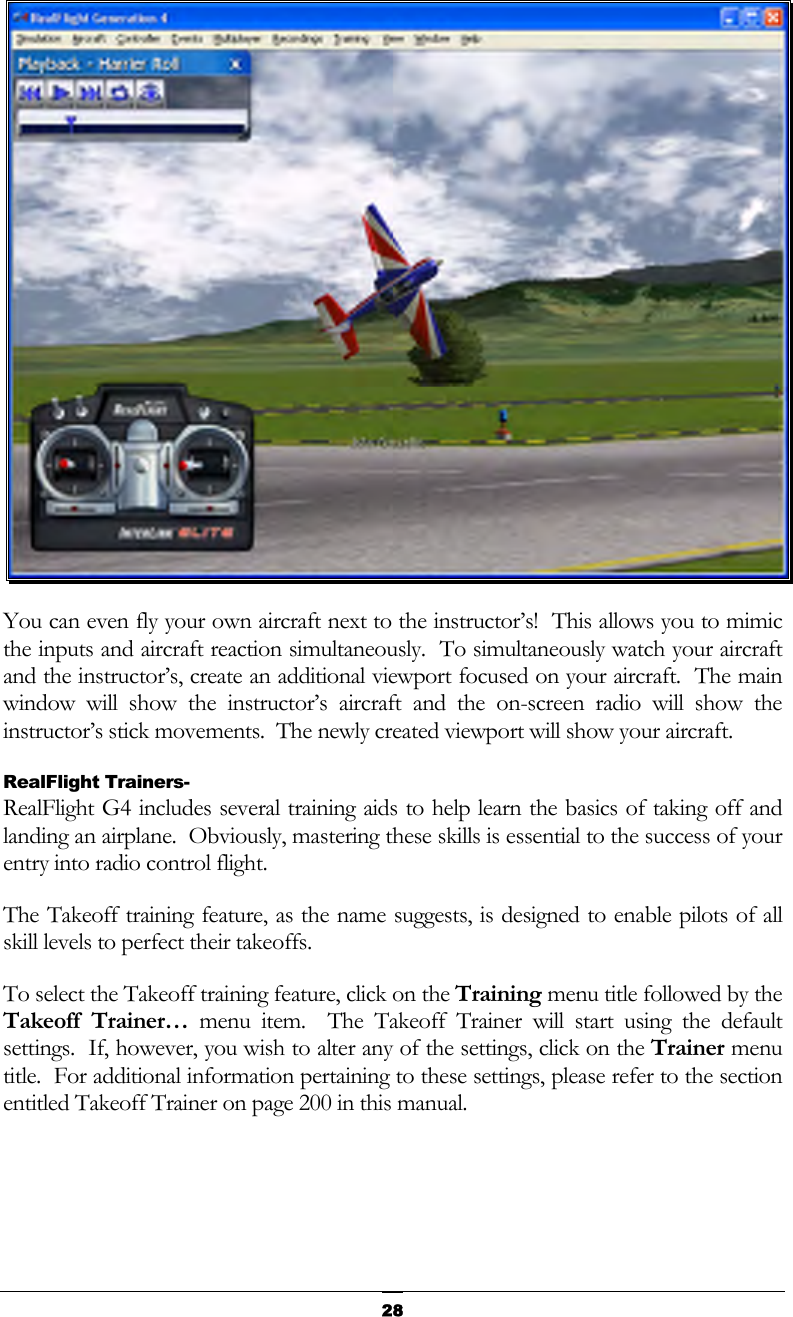
![27related maneuver, click the [+] (plus) near the airplane. Alternatively, you may also double-click the word itself (e.g., airplane). This brings up the pilot selections. To select amongst the pilots, click the [+] (plus) which precedes their name. Alternatively, you may double-click the pilot’s name. To select a maneuver, double-click the name of the maneuver itself. Alternatively, highlight the name of the maneuver by clicking on it, then select OK. After you have selected a maneuver, click OK to proceed. RealFlight G4 will automatically load the default airport and then start the VFI recording. Once the VFI starts, you will see the instructor’s aircraft fly the maneuver and hear the instructor’s voice explaining how it’s done. As depicted below, you can also watch the instructor’s actual stick movements using the on-screen, digitized R/C radio.](https://usermanual.wiki/Futaba/FS006H.User-Manual-I/User-Guide-859426-Page-32.png)
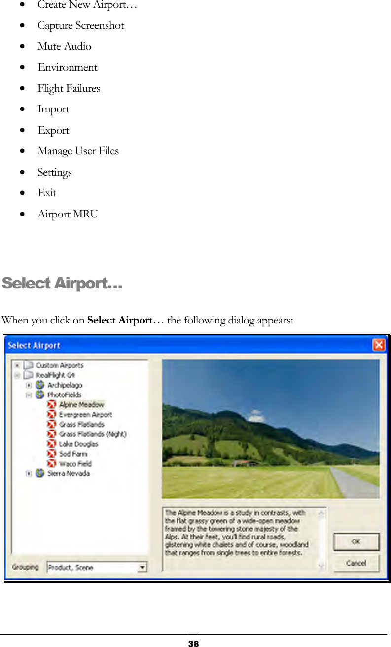
![39This dialog lets you choose the flying site that you wish to use for your flight. Each location offers its own unique characteristics and challenges. The list on the left of the dialog box displays all of the flying sites available to you. If you have created any flying sites, those sites will also be visible here. The flying sites are listed in files and folders in accordance with the software from which they were loaded. If, for example, you have installed Expansion Pack 2, the sites from this disk will be listed, alphabetically, beneath the Expansion Pack 2 folder. You can change how the airports are organized by clicking on the Grouping drop-down and select another grouping option. The options are: Product, Scene: As explained above, airports are first grouped into folders by the product in which they are contained. Within each group they are then grouped further by scene. Product: Airports are grouped by product alone. Scene: Airports are grouped by scene alone. None: Airports are not grouped into folders at all. Rather, they are listed alphabetically. Click the [+] (plus) or the [-] (minus) symbol to reveal or hide the respective airports within these folders. To select an airport, click on the name of the airport at which you wish to fly. The rotating image on the right side of the screen provides you with a preview of what to expect at the desired location. The dialog box below the terrain map contains a description and pertinent information regarding the highlighted airport. Have some fun while you’re in the Select Airport dialog. Using the mouse, click and drag the preview screen to point the camera angle to your choosing. To resume rotating automatically, right-click the preview screen. When you are satisfied with your selection, click OK to return to your flight using the new airport selection. The Cancel button will return you to the simulation at the previously selected flying site. Change airports simply by using the InterLink Elite. Press the Menu/Select button, then, using the Data Lever, move down one tab and press the Menu/Select button again. This will bring up the Select Airport dialog window. You can continue using the QuickSelect buttons in this dialog to select a new airport, or press Reset to resume flying without making any changes.](https://usermanual.wiki/Futaba/FS006H.User-Manual-I/User-Guide-859426-Page-44.png)
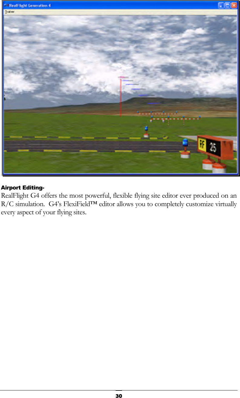
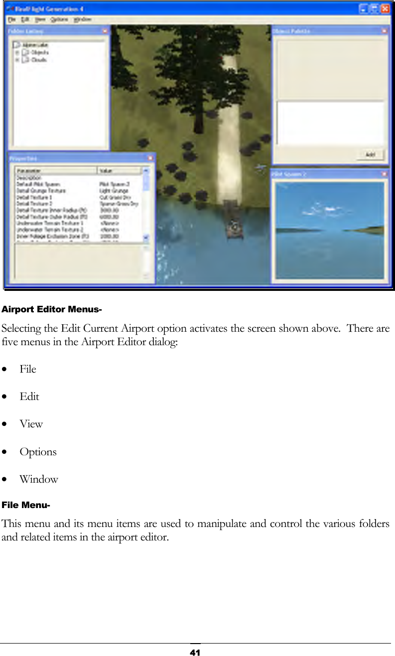
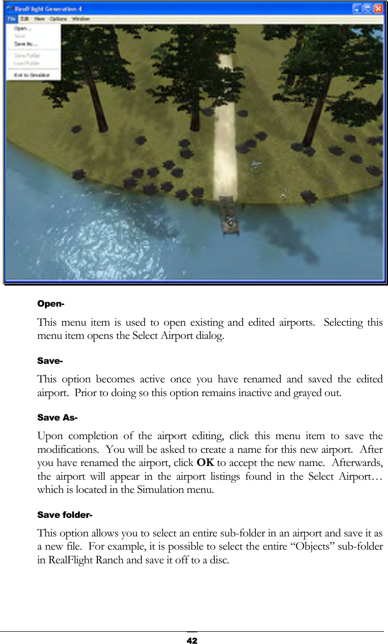
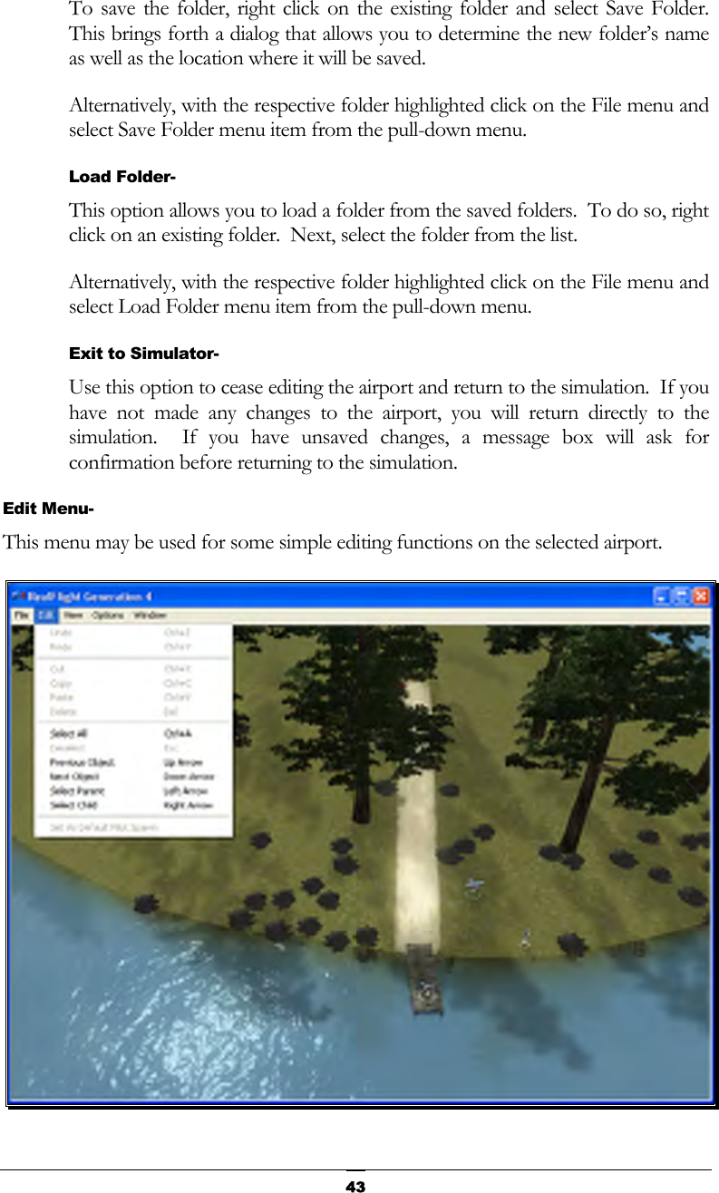
![40 Movement Modes If applicable to the respective airports, Generation 4’s Movement Modes allow you to explore the scenery without an aircraft. Movement is not possible at PhotoField airports. To select a Movement Mode, press the ‘Q’ key on your keyboard. You can press the ‘Q’ key repeatedly to cycle through the available modes: Walk, Fly or Hover. Walk mode simulates the effect of you, the pilot, physically walking across the field, complete with sound effects. The Fly mode allows you to move through the air and position the camera anywhere that you desire. Once you have entered the desired Movement Mode, use the ‘W’, ‘S’, ‘A’ and ‘D’ keys on your keyboard to control the movements. If you wish to increase the speed of your movement, press and hold the Shift key at the same time you are using the ‘W’, ‘S’, ‘A’ or ‘D’ key. The mouse wheel controls the angle or height at which you traverse the scenery. To increase the altitude, roll the wheel away from you. This is known as the Hover Mode. You may also control the zoom levels during your travels. Press the [+] (plus) key to Zoom In and the [-] (minus) key to Zoom Out. The Backspace key resets the zoom level to its default value. Edit Current Airport… RealFlight G4 offers unparalleled freedom to edit flying sites. You can add and remove objects, alter their location, rotate, and even resize items. It is also possible to alter the atmospheric or lighting conditions at the various flying locations. The first several times you access the airport editing function, the possibilities might seem daunting. It will require some getting used to before you are comfortable with this feature and its related functions. The best way to do so is to simply dive in and experiment. To modify the currently selected flying location, click the Simulation menu followed by the Edit <Current Airport>… menu item, where <Current Airport> is the name of the airport you have loaded at the moment. This activates RealFlight G4’s FlexiField flying site editor, with the currently active airport loaded and ready to edit.](https://usermanual.wiki/Futaba/FS006H.User-Manual-I/User-Guide-859426-Page-45.png)
![46and Normal Camera. These modes, as well as the methods to access them will be discussed in depth in the sections that follow. Pan Camera- The Pan Camera option allows the camera to shift the vantage point on the selected scenery. There are several ways to access the Pan Camera mode. The first, and probably the easiest, is to press the ‘C’ key on your keyboard. Alternatively, you may right click on the scene and select Pan Camera from the available options. The final method that may be used is to select Pan Camera through the View menu and Mode menu item. To increase the pan view, rotate the mouse wheel towards the computer screen. Alternatively, you may also press the [-] (minus) key on the number pad of the keyboard. This causes the camera to pan out incrementally. Conversely, to decrease the pan view, either rotate the mouse wheel away from the computer screen or press the [+] (plus) key on the keyboard’s number pad. This causes the camera to pan in incrementally. To move an object within the scene, left click on the object with the mouse, continue to hold the button down, and move the mouse within the scene. The selected object will move along with the mouse cursor. You can exit this mode by using the menus or by hitting the ‘Z’ key, which returns you to the normal viewing mode. Pivot Camera- The Pivot Camera mode, as the name suggests, pivots or rotates the camera in relationship to a particular object or location. There are several ways to access the Pivot Camera mode. The first, and probably the easiest, is to press the ‘X’ key on your keyboard. Alternatively, you may right click on the scene and select Pivot Camera from the available options. The final method that may be used is to select Pivot Camera View menu and Mode menu item. To increase the pivot view, rotate the mouse wheel towards the computer screen. Alternatively, you may also press the [-] (minus) key on the number pad of the keyboard. Doing so will cause the camera to shift incrementally.](https://usermanual.wiki/Futaba/FS006H.User-Manual-I/User-Guide-859426-Page-51.png)
![47Conversely, to decrease the pivot view, either rotate the mouse wheel away from the computer screen or press the [+] (plus) key on the keyboard’s number pad. Again, this will shift the camera incrementally. To exit the Pivot Camera feature, right click in the editing view once again and then mouse click the desired option in the popup menu. You can also exit this mode by hitting the ‘Z’ key, which returns you to the normal viewing mode. Normal Camera- This mode returns the camera to its normal, or default perspective. There are several ways to access the Normal Camera mode. The easiest is to simply press the ‘Z’ key on the keyboard. Alternatively, you may right click in the scene and select Normal Camera from the options listed. Finally, you may select Normal Camera through the View menu and Mode menu item. Center View on Selection- This option centers the vantage point on a particular object. This is useful for repositioning, resizing, rotating, etc. If you have not selected an object from the Folder Listing or highlighted an object in the scene, this option will remain inactive or grayed out. If, however, you have made a selection or highlighted an object, there are several ways to select the Center View on Selection option. Simply right click on the selected object or folder in the Folder Listing. Alternatively, in the scene, right click on the highlighted object and select the Center View on Selection from the options listed. The final option is to use the View menu and select the Center View on Selection option. To magnify the view or zoom in on the selected item, press the [+] (plus) key on the keyboard. Each time you press the [+] (plus) key or select the Zoom In menu item, the zoom level increases incrementally. Alternatively, you may select the Zoom In option from the View menu. To decrease the magnification, or zoom away from the selected item, press the [-] (minus) key on the keyboard. Each time you press the [-] (minus) key or select the Zoom Out menu item, the zoom level decreases incrementally. Alternatively, you may select the Zoom Out option from the View menu.](https://usermanual.wiki/Futaba/FS006H.User-Manual-I/User-Guide-859426-Page-52.png)
![48Fit Selection in View- This option is utilized to ensure that your selection fits in the view. If, for example, your zoom magnification is at an extremely high level, the object may not completely fit on the screen. This feature ensures that it will. To access the Fit Selection In View, right click on the highlighted object in the scene and select the Fit Selection In View from the options listed. The final option is to use the View menu and select the Fit Selection In View option. To magnify the view or zoom in on the selected item, press the [+] (plus) key on the keyboard. Each time you press the [+] (plus) key or select the Zoom In menu item, the zoom level increases incrementally. Alternatively, you may select the Zoom In option from the View menu. To decrease the magnification, or zoom away from the selected item, press the [-] (minus) key on the keyboard. Each time you press the [-] (minus) key or select the Zoom Out menu item, the zoom level decreases incrementally. Alternatively, you may select the Zoom Out option from the View menu. Zoom In- Click this menu item to magnify or zoom in on the selected item. Alternatively, you may magnify the view or zoom in on the selected item by pressing the [+] (plus) key on the keyboard. Each time you press the [+] (plus) key or select the Zoom In menu item, the zoom level increases incrementally. Zoom Out- Click this item to reduce the magnification, or zoom out of the current view. Alternatively, press the [–] (minus) key on the keyboard. Alternatively, you may zoom out via G4’s menus. Each time the [-] (minus) key or the Zoom Out menu item are pressed or selected, the view will decrease incrementally. Zoom Reset- This menu item resets the view to the default magnification. Alternatively, you may also press the Backspace on the keyboard to reset the zoom to its default value. Options Menu- The Options Menu allows you to adjust how many of the functions in the airport editor will work.](https://usermanual.wiki/Futaba/FS006H.User-Manual-I/User-Guide-859426-Page-53.png)
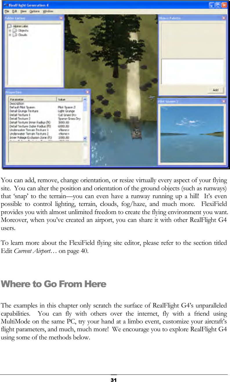
![53 To determine what items are contained within the Objects and Clouds folders, click on the [+] (plus) or double-click on the name itself (e.g., Objects). Doing so brings up the various sub-folders that are contained within the main item. As denoted by the [+] (plus) symbols, these folders, in turn, also have another level. Again, to open these respective levels, click on the [+] (plus) icon or double-click the folder name. Alternatively, clicking on an object in the scene will highlight the respective object. It will also open the folder that contains the object. The converse is also true, clicking the folder or object in the Folder Listing menu will highlight the respective item as well. If you wish to move an object from one folder to another, mouse click and hold the object to be moved. Next, drag the object to the desired location (folder) using the mouse and release. The object will be listed at the bottom of the folder in which it has been situated. Please note: this removes the object from the original folder. You may use either of two methods to delete an object from the folder, and therefore the scene as well.](https://usermanual.wiki/Futaba/FS006H.User-Manual-I/User-Guide-859426-Page-58.png)
![55Object Palette Window- The Object Palette window is used to add a new object or objects to the airport. The object window consists of two separate sections: the preview box in the top section of the window, and the objects list in the bottom section. All objects are grouped according to their root directory. Within the root directory the grouping is further refined. For example, you will find all available benches in the Benches, Chairs and Tables group. This, of course, assumes that you are utilizing the Product, Type, Name or Type, Name as determined by the Add Object Grouping Selection in the Options menu. Each object group is preceded with a [+] (plus) and an icon. The [+] (plus) indicates that there is another expansion level, or selection, available to you. Clicking on the [+] (plus) or double-clicking the respective root directory name (e.g., RealFlight G4) will bring forward the pull-down menu of the items contained within the specified folder. If, for example, you wanted to add a bench to the current airport, take the following steps:](https://usermanual.wiki/Futaba/FS006H.User-Manual-I/User-Guide-859426-Page-60.png)
![561. Click on the [+] (plus) icon in front of the Benches, Chairs and Tables group (or, double-click the group name itself). This reveals the next expansion level to you. 2. From this expansion list, select the ‘Bench’ object. The selected object appears in the preview box. 3. Click the Add button, which adds the object to the scene. You will find additional information pertaining to object placement, positioning, etc., in the Properties section of this chapter. You may use any one of several available methods to change the location of an object in the airport. To use the drag and drop method, click on the object to highlight it, as shown below. Once you have highlighted the object, press and hold the mouse button. Move the mouse to the desired location and then release the button to drop the object in the new location. Alternatively, with the object highlighted, right click the mouse elsewhere in the scenery. This brings up a pop-up menu with several options available to you. To move the selected object, point the mouse to the location that you desire and click the Move Here option. G4 also allows you to easily replicate the selected objects. To do so, hold the ‘Ctrl’ key down, click and hold the mouse button and use the mouse to drag the object to a new location. You will see that the original object stays in place. Release the mouse button and the ‘Ctrl’ key to drop the new item in place. Once you have added an object to the airport, you can modify it freely. Refer to the Properties Window – Object Selection section for information on how to do so. Pilot Preview- This window provides you with the ability to view the scene from the pilot’s perspective. It is very useful when editing PhotoField airports.](https://usermanual.wiki/Futaba/FS006H.User-Manual-I/User-Guide-859426-Page-61.png)
![57 The number of pilot perspectives available to you varies; dependent upon the selected scene. For example, RealFlight Ranch offers: Runway Center, Runway End and Helipad as the viewing options. To select amongst these options, open the Spawn Folder in the Folder Listing. Use the up/down arrow keys on the keyboard or the mouse to select the desired perspective. It is also possible to modify the selected vantage points. For example, you may Zoom In and Out, or simply scan the horizon. Note that in order to modify the vantage point, the Pilot Preview window must be the active window. To ensure that the Pilot Preview window is the active window, simply click on, or in, this window. To magnify the view or zoom in on the selected item, press the [+] (plus) key on the keyboard. Each time you press the [+] (plus) key or select the Zoom In menu item, the zoom level increases incrementally. To decrease the magnification, or zoom away from the selected item, press the [-] (minus) key on the keyboard. Each time you press the [-] (minus) key or select the Zoom Out menu item, the zoom level decreases incrementally. In most cases, you can also use the scroll wheel on the mouse to zoom in and out on the scenery RealFlight also allows you to scan the scene. To do so, press and hold the mouse button. Moving the mouse will shift the scenery.](https://usermanual.wiki/Futaba/FS006H.User-Manual-I/User-Guide-859426-Page-62.png)
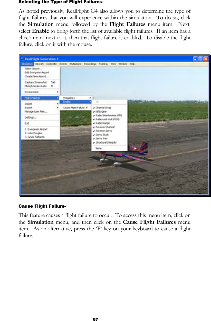
![66menu is visible, simply mouse click on one of the options in the pull-down menu. Alternatively, you can adjust the rate of occurrence in the Settings… menu item. To access this menu item, click on the Simulation menu followed by the Settings… menu item. Next, click on the Flight Failures listing. You can bring forth the Flight Failures options by clicking on the [+] (plus) or by double-clicking on the Flight Failures listing itself. To adjust the frequency of occurrence, click on the value as indicated in the column to the right of the probability indicator. The Settings section on page 75 discusses the Flight Failures options in detail. If you do not wish to experience any flight failures, click the Never option in the drop-down menu. Conversely, if you wish to gain a great deal of experience at handling emergencies, click the Always option. The Always options means that each time you reset the aircraft, something is guaranteed to go wrong. Maybe not right away – an engine failure will usually wait until some entirely inconvenient time to reveal itself, but it will happen. The Rarely option corresponds to roughly a 5% chance per reset that something will fail.](https://usermanual.wiki/Futaba/FS006H.User-Manual-I/User-Guide-859426-Page-71.png)
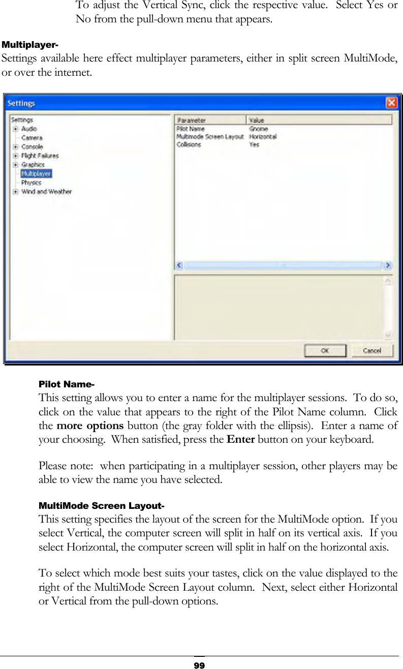
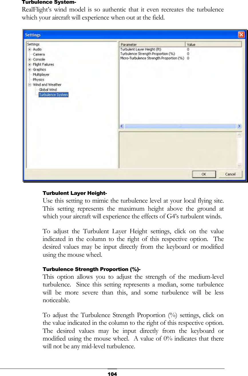
![76 The Settings that are available to you are as follows: • Audio • Camera • Console • Flight Failures • Graphics • Multiplayer • Physics • Wind and Weather Audio- Audio settings are split into two different categories which are as follows. Double-click on the Audio name, or click on the [+] (plus) to expand the list and show the Audio options.](https://usermanual.wiki/Futaba/FS006H.User-Manual-I/User-Guide-859426-Page-81.png)
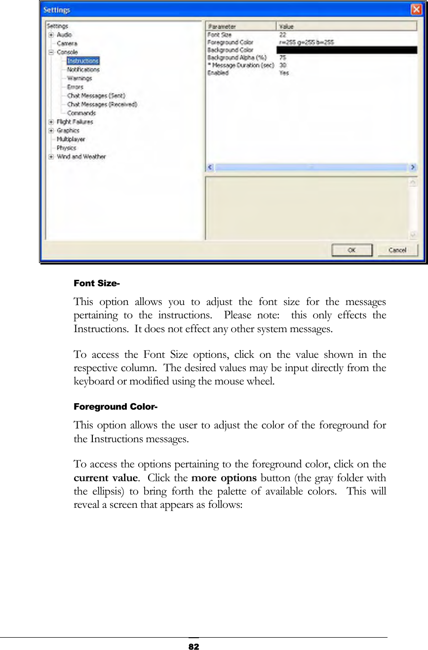
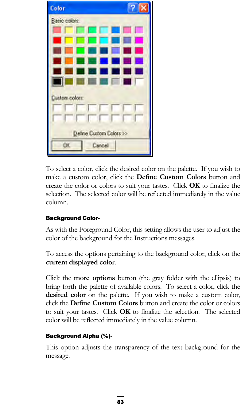
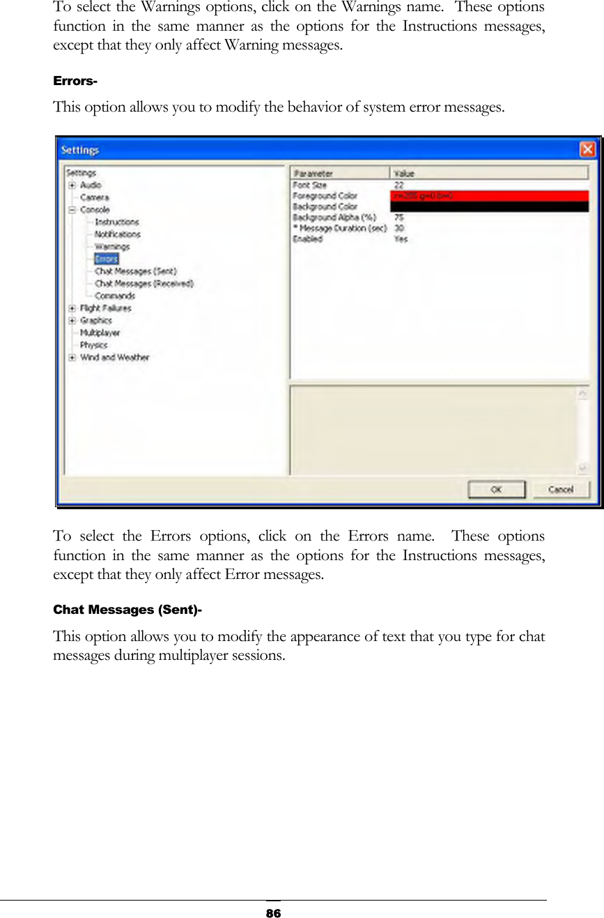
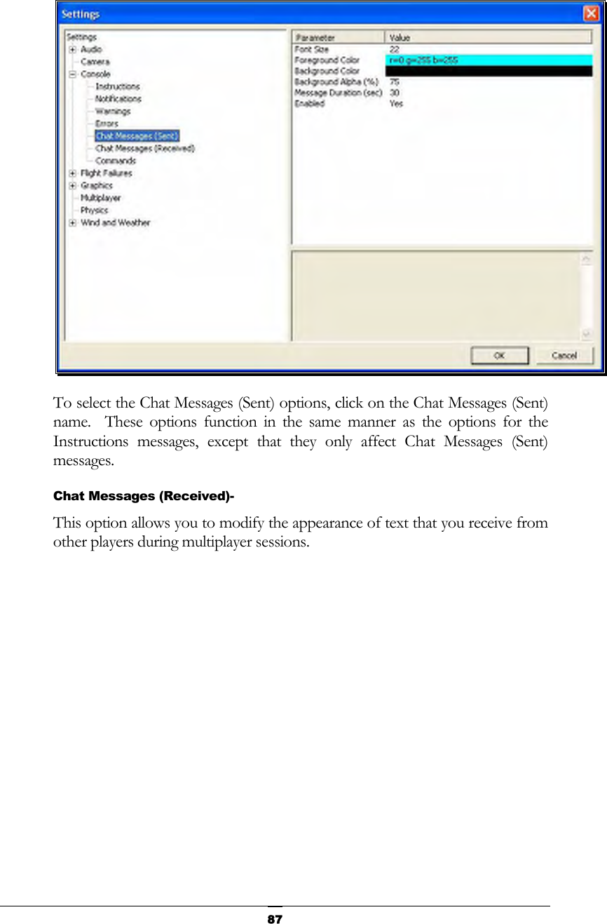
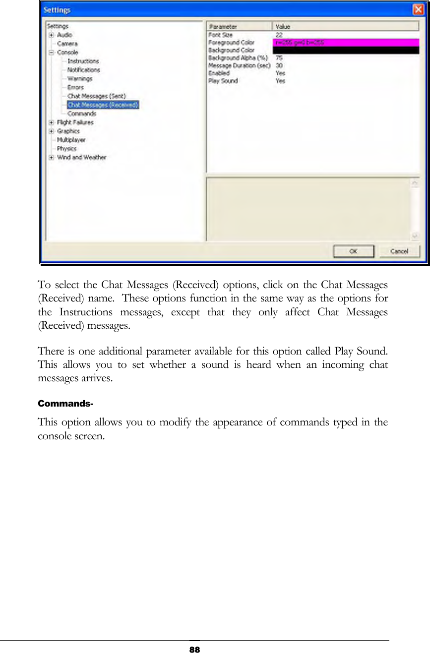
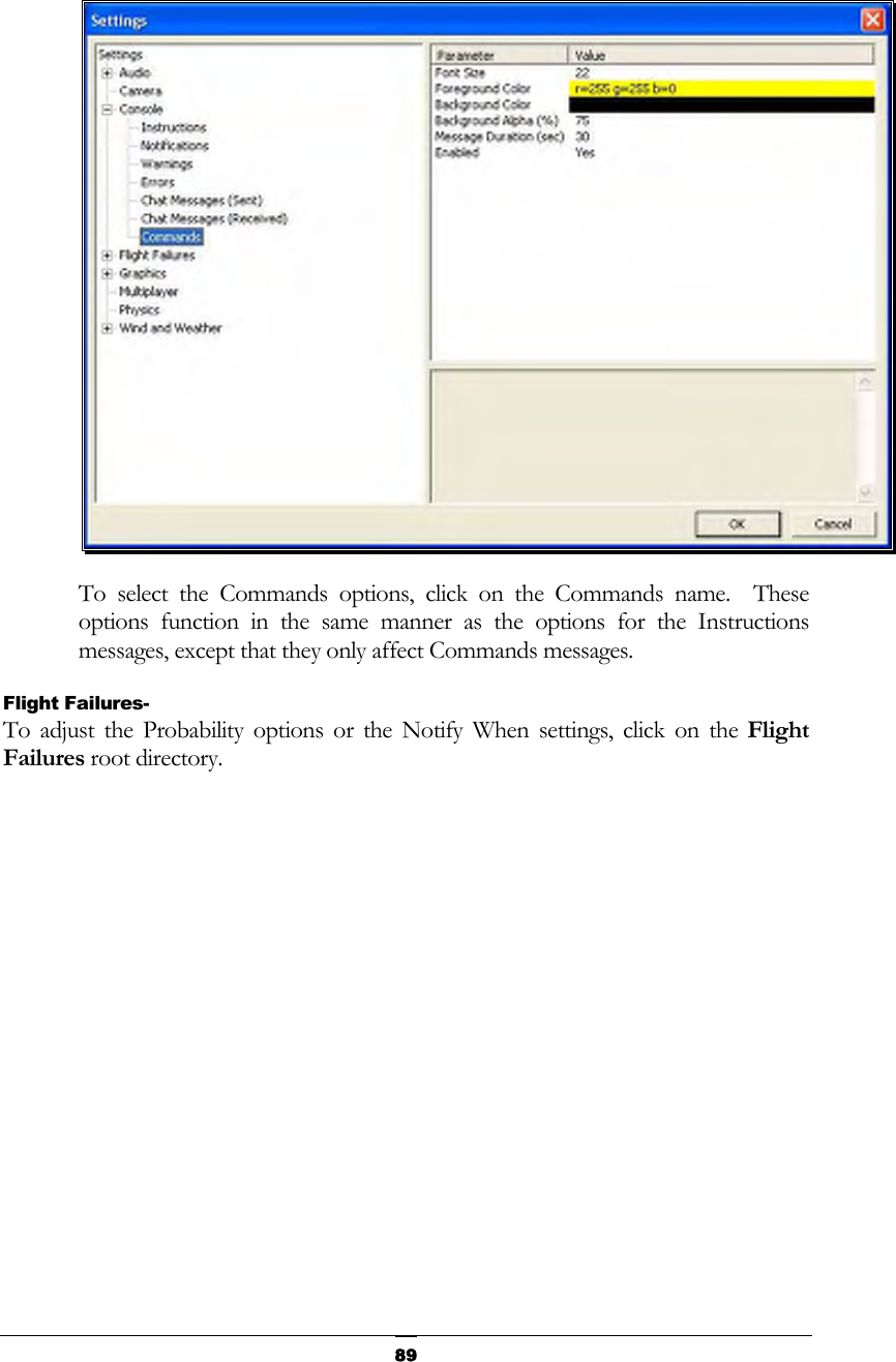
![81Clear on Reset- This setting controls whether all the on-screen messages are cleared when the aircraft resets. This prevents the screen from becoming overly cluttered with messages and information. Using either the up/down arrow keys on the keyboard, or the mouse, select either Yes (messages automatically clear) or No (messages remain on-screen after a reset) from the pull-down listings. If using the up/down arrow keys, press Enter to finalize your selection. Double-clicking on the Console name or clicking on the [+] (plus) will bring forth the following options: • Instructions • Notifications • Warnings • Errors • Chat Messages (Sent) • Chat messages (Received) • Commands Each of the System Messages screens is independently adjustable and may be tailored to suit your personal preferences. For information on how to do so, please read the following section. Instructions- As the name suggests, modifications will affect only the System Instructions.](https://usermanual.wiki/Futaba/FS006H.User-Manual-I/User-Guide-859426-Page-86.png)
![90 Double-click on the Flight Failures name or click on the [+] (plus) to expand the list and show the Flight Failures options. RealFlight defaults all Flight Failures to enabled (active). Each item may be enabled or disabled individually. To disable a specific flight failure, click on the respective failure located within the pull-down list. Next, click on the Yes value as indicated in the value column. This brings forth the Yes/No pull-down list. To disable the respective failure, simply choose the No option. For example, to disable the Reverse Servo flight failure: 1. Select the Reverse Servo option in the Flight Failures sub-menu 2. Click the Yes in the right hand pane 3. Select No from the pull-down list Probability- To adjust the frequency of occurrence, click on the value as indicated in the column to the right of the probability indicator. If you do not wish to experience any flight failures, select the Never option in the drop-down menu. Conversely, if you wish to gain a great deal of experience at handling emergencies, click the Always option. Notify When- This setting allows you to determine if, or when, RealFlight notifies you as to the flight failure experienced.](https://usermanual.wiki/Futaba/FS006H.User-Manual-I/User-Guide-859426-Page-95.png)
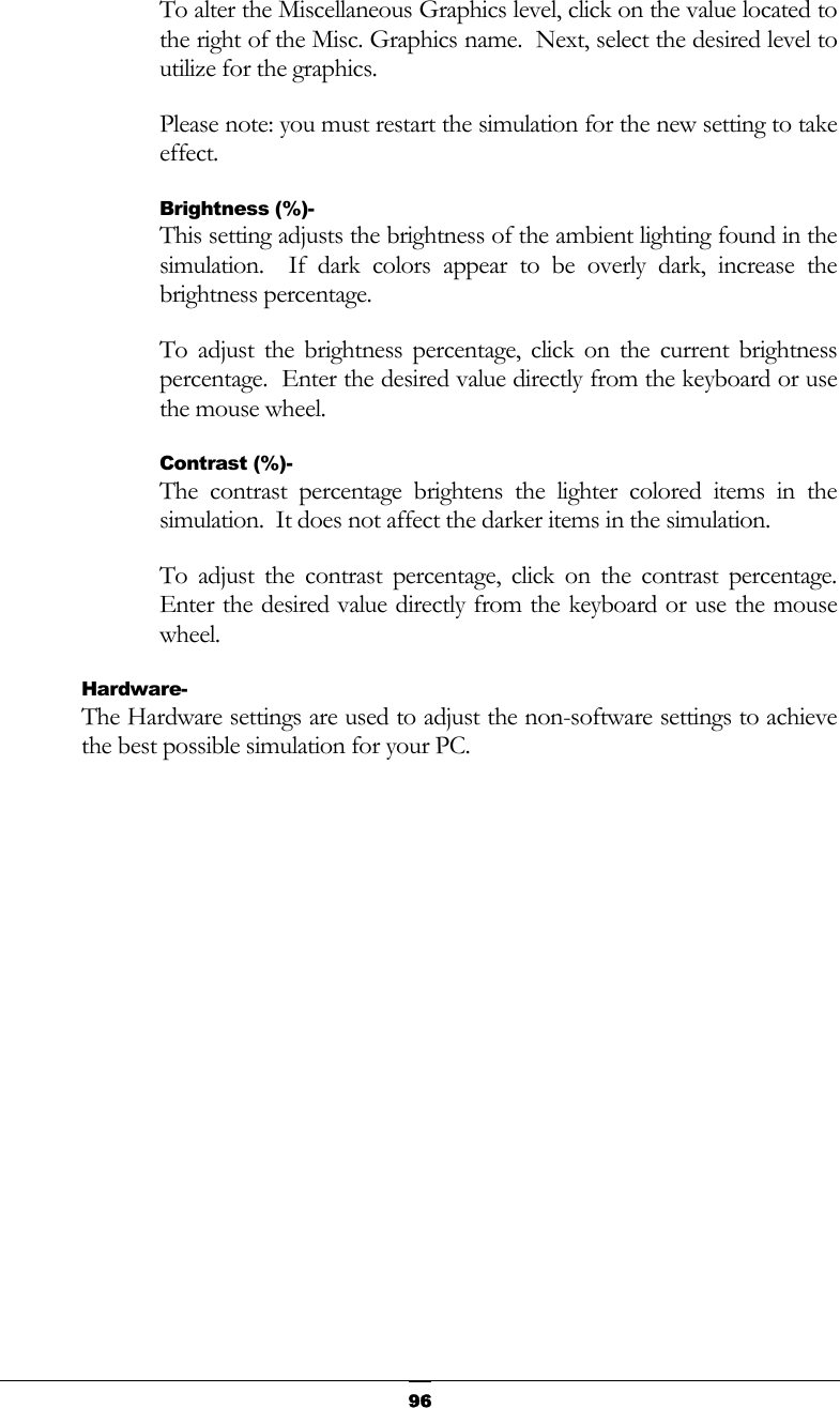
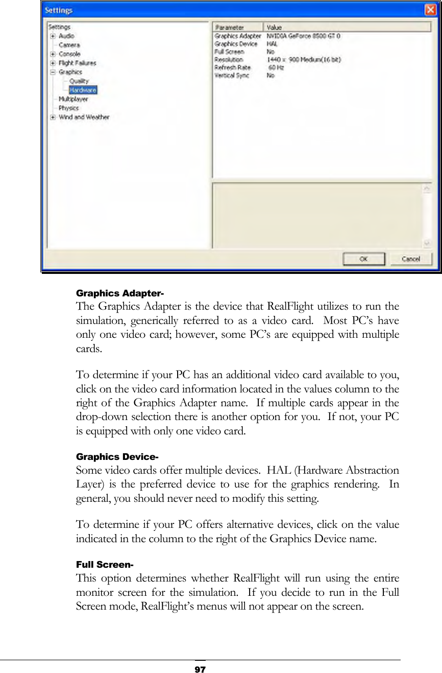
![92Multiple Failures which allows this flight failure to be triggered more than once during a flight. Graphics- Double-click on the Graphics name or click on the [+] (plus) to expand the menu and display the various Graphics options available to you. Quality Options- The Quality options are quite useful in fine-tuning your simulator to ensure that it runs as efficiently and realistically as possible on your PC. Use the settings in the Graphics options to obtain the perfect blend of optimal visuals and performance from your PC. If you are experiencing slow frame rates or other performance issues, it may be prudent to turn down some graphics quality options. Note that many of the adjustments will not take place immediately. In many cases, you will need to restart the simulator in order for the option to take effect. Clouds- This option determines whether your flying sites will include clouds in the skyline.](https://usermanual.wiki/Futaba/FS006H.User-Manual-I/User-Guide-859426-Page-97.png)
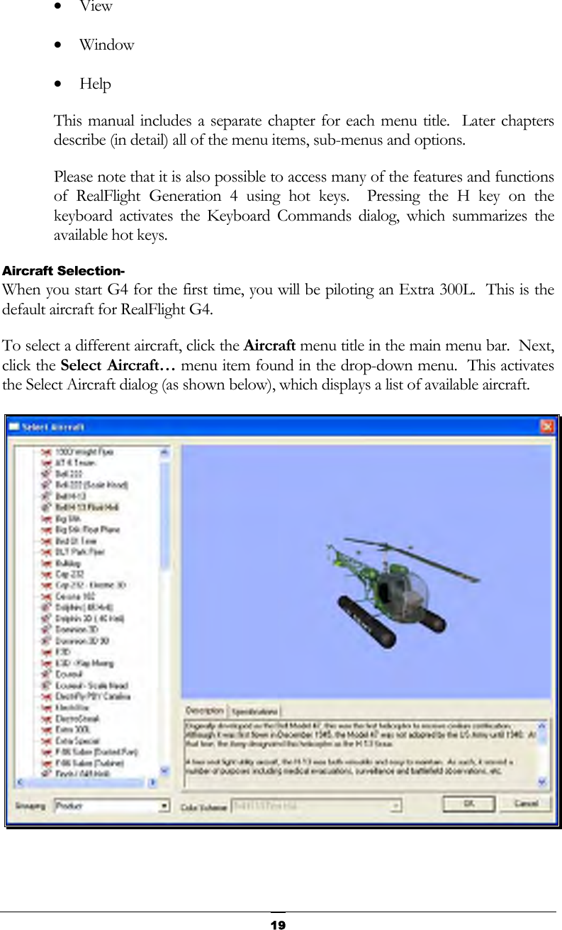
![109 This dialog allows you to select the aircraft that you wish to fly. Change aircraft simply by using the InterLink Elite. Press the Menu/Select button, then, with the airplane tab highlighted press the Menu/Select button again. This will bring up the Select Aircraft dialog window. You can continue using the QuickSelect buttons in this dialog to select a new aircraft, or press Reset to resume flying without making any changes. The list on the left of the dialog box displays all of the aircraft available to you. If you have created any customized aircraft, they will also appear in this list. By default, the aircraft are listed in files and directories in accordance with the software from which they were loaded. If, for example, you have installed Expansion Pack 2, the aircraft from this disc will be listed, alphabetically, beneath the Expansion Pack 2 directory. Click the [+] (plus) or [-] (minus) symbol to reveal or hide the aircraft within these directories and folders. Aircraft Selection Every aircraft has its own unique flying characteristics, special features and functions. To view an aircraft from the listings, simply use the mouse to click on the aircraft name.](https://usermanual.wiki/Futaba/FS006H.User-Manual-I/User-Guide-859426-Page-114.png)
![110Alternatively, use the up/down keys on the keyboard to scroll through the list, one aircraft at a time. The first time an aircraft is selected, G4 creates a collision mesh for the aircraft. This process may take a few seconds to complete. A progress bar will appear while the collision mesh is being calculated. Click the [+] (plus) symbol to reveal the aircraft contained within the folder. Using either the up/down arrow keys on the keyboard or the mouse, select the desired aircraft from the listings. If utilizing the up/down arrow keys, click OK to finalize your selection. Alternatively, if using the mouse, double-click on the aircraft to load it. Have some fun while you’re in the Select Aircraft dialog. Using the mouse, click and drag the preview screen to point the camera angle to your choosing. Use the scroll wheel to zoom in or out. Or, move the gimbals to see the control surfaces move. To resume rotating automatically, right-click the preview screen. Description/Specifications- The pane below the Aircraft Preview box shows either the aircraft description or aircraft specifications. This box provides you with a brief history of the aircraft (if applicable) and serves to provide you with specific information pertaining to the model selected. Using the mouse, select either the Description or Specifications tab. Grouping- This list controls how the dialog organizes the list of available aircraft. By default, the aircraft are sorted by Product. Here is an explanation of the different sorting methods: Product, Airframe: Aircraft are grouped first by which product they are found in (all custom aircraft will be in the “Custom Aircraft” folder). Within each product, the aircraft are further grouped by airframe. For example, “NextSTAR” and “NextSTAR with AFS” are both found in the NexSTAR airframe folder. Product: Aircraft are grouped by product alone. Airframe: Aircraft are grouped by airframe, not by product. Individual aircraft are grouped inside each airframe folder. None: There is no grouping at all. All aircraft are sorted alphabetically. Color Scheme- If applicable, this list contains the alternative trim schemes for the selected model. If the Color Scheme dialog is grayed out, there are no alternative trim schemes available for this particular aircraft.](https://usermanual.wiki/Futaba/FS006H.User-Manual-I/User-Guide-859426-Page-115.png)

![145Setting the Pass Through Interface- After completing the Controller Calibration… and the Channel Mapping… procedures, select the desired aircraft. Next, select the Edit Current Aircraft menu item. Highlight the aircraft root (name of the aircraft) and select the value for the Radio Type. Using either the mouse or the up/down arrow keys on the keyboard, select the Pass Through option from the pull-down menu. Mapping channels to Servos- If any channels are mapped to the wrong functions on the aircraft, edit the aircraft using the following procedure. Click the Edit Current Aircraft menu item. Access the Electronics options. Double-click the Electronics name or click on the [+] (plus). Select the incorrectly mapped channel from the pull-down list that activates. To change the respective channel of operation, click on the corresponding value and select the appropriate option from the pull-down list. IMPORTANT! Do not change the servo mapping using the Channel Mapping… menu item. If you do so, the change will also affect ALL stock aircraft. Instead, simply change the servo mapping using the Electronics options above for a single aircraft. Sharing Aircraft that use the Pass Through Interface- In most cases, when you make a custom aircraft that uses the Pass Through Interface option, you will not be able to provide that aircraft to your friends or submit it to the RealFlight Model Swap Page. This is because the RealFlight software does not receive the necessary input for the radio programming. Consequently, you would have to provide other RealFlight users with all of your R/C radio’s settings for that particular aircraft. Moreover, they would have to have the exact same R/C transmitter in order for them to use the aircraft. These complications effectively prohibit swapping aircraft under these conditions. InterLink Elite Controller Tips What if my transmitter has fewer channels than the model I select? This issue can arise when you use your own transmitter to control RealFlight G4. In this situation, we highly recommend that you use the InterLink Elite controller. When to use the Channel Mapping, and when to use the Software Radio or Servo page- This issue arises only if you use your own transmitter to control RealFlight. When you use the InterLink Elite controller as a mockup transmitter, you should not alter the Channel Mapping.](https://usermanual.wiki/Futaba/FS006H.User-Manual-I/User-Guide-859426-Page-150.png)