Contents
- 1. User Manual I
- 2. User Manual II
User Manual I


GREAT PLANES
RealFlight Generation 4 and the
InterLink Elite Controller
© Great Planes Model Manufacturing Company
P.O. BOX 788, Urbana, IL 61801

Table of Contents
Introduction 1
RealFlight G4 Feature Highlights 2
How to read this manual 5
Before You Begin 7
System Requirements 7
Video and Sound Cards 8
Getting the Most out of RealFlight 9
Getting Started 11
Installing RealFlight G4 11
Using Your Own R/C Radio 15
Exploring RealFlight G4 17
Where to Go From Here 31
The InterLink Elite Controller 33
Start Flying! 34
The Simulation Menu 37
Select Airport… 38
Edit Current Airport… 40
Utilizing the Editor 52
Create New Airport 58
Capture Screenshot 58
Mute/Unmute Audio 59
Environment 60
Flight Failures 65
Import 68
Export 70
Manage User Files 73
Settings 75
Exit 105
Airport MRU 106
The Aircraft Menu 107
Aircraft Selection… 108
Edit Current Aircraft 111
Select Color Scheme 123
Save Color Scheme As… 124
Remember Aircraft Position 127
Clear Aircraft Position 128
Reset Position 129
Kill Engine 129
Aircraft MRU 130
Controller Menu 133
Select Controller 134
Controller Calibration 135
Channel Mapping… 137
Joystick Mode vs. Transmitter Mode 140
InterLink Elite Controller (Joystick Mode)
140
InterLink Elite Controller (Transmitter
Mode) 141
Transmitter Mode: Joystick Emulation
Interface 143
Transmitter Mode: Pass Through Interface
144
InterLink Elite Controller Tips 145
Events Menu 147
Autorotation/Deadstick 149
Autorotation/Deadstick Instructions 152
Freestyle 154
Freestyle Instructions 157
Limbo 158
Limbo Instructions 162
Pylon Racing 163
Pylon Racing Instructions 166
Spot Landing 168
Spot Landing Instructions 171
Options 173
End Current Event 174
Forfeit Turn 175
Multiplayer Menu 177
Chatting 179
Host 179
Join 182
Disconnect… 184
Boot Player… 185
Publish Hosting Information 186
Enter MultiMode 187
Recordings Menu 191
Start Recording 192
Stop Recording 193
Open Recording… 193
Record Microphone Input 196
Recordings MRU 197
Training Menu 199
Takeoff Trainer 200
Landing Trainer 205
Heli Hover Trainer 209
Airplane Hover Trainer 216

Heli Orientation Trainer 222
Virtual Flight Instruction 224
View Menu 229
Show 230
Camera Type 231
Camera Position 232
Look At 233
Quick Look 234
Zoom Type 235
Zoom In 237
Zoom Out 237
Zoom Reset 238
Head Tracking 239
Window Menu 241
Show Title Bar 242
Gadgets 243
Arrange 255
Close All 255
Viewport List 256
Help Menu 259
Contents 260
Keyboard Commands 261
About 262
License 263
Websites 264
Basics of Flying 267
Airplane Basics 267
Helicopter Basics 270
Helicopter Flight 276
RealFlight G4 Launcher 277
Run RealFlight 278
Additional Options 278
If You Experience Difficulties287
How to Get Help and Information 287
Before You Do Anything Else 288
If You Need Additional Assistance 290
Examples of Common Problems and
Solutions 291
Glossary 293
Index 311
License 317
Credits 321

1
Introduction
Welcome to the RealFlight Generation 4 R/C Flight Simulator
(also known as RealFlight G4, or simply G4).
ealFlight G4 is, without question, the most advanced R/C aircraft simulation
available. RealFlight G4 is so technologically advanced and so realistic, you’ll
find it hard to believe that it’s only a simulation. The culmination of many
years of development and design, G4 offers advancements that will serve to
fine-tune flying the skills of even the most seasoned R/C veteran. If you’re an entry-
level R/C-er, RealFlight G4 is the ideal way to learn to fly, practice maneuvers, feel the
effects of design modifications, or just have an incredible amount of fun.
RealFlight G4 includes over 50 models that look and fly like the real thing, plus a
multitude of flying sites - each with their own unique ‘feel’ and distinctive
characteristics. In addition, G4 offers its users the most powerful, most flexible aircraft
and flying site editors ever unveiled to the modeling community, allowing modelers to
experiment with a virtually unlimited number of parameters. G4 enables you to
change the look and feel of a flying site with nothing more than a few keystrokes, the
click of the mouse and a little imagination. The integrated AccuModel™ aircraft editor
makes modifying aircraft just as easy.
RealFlight G4 also offers a wide array of tools to help you understand how to use the
program and how to improve your R/C piloting skills. This extensive manual file
explains every feature and option as well as how to use them. Our Virtual Flight
Instruction feature, Heli Hover Trainer, Airplane Hover Trainer, Takeoff and Landing
Trainer and Heli Orientation Trainer provide on-the-fly learning opportunities, and our
trained and dedicated Product Support staff is ready to provide help when you need it.
No other R/C simulator goes further to enrich your R/C experience.
The following section briefly outlines some of the exciting features in RealFlight G4.
We strongly suggest that you peruse this manual in its entirety before running the
software. Subsequent chapters will describe all RealFlight features in complete detail.
Chapte
r
1
R

2
Finally, we’d like to express our gratitude to you for purchasing RealFlight G4. We
think you will be enormously pleased with G4. Have fun flying!
RealFlight G4 Feature Highlights
This section briefly outlines some of the new features included in RealFlight G4 with
the USB InterLink Elite Controller. RealFlight G4 and the multi-patented InterLink
Elite Controller incorporate a significant number of enhancements and improvements
over previous RealFlight systems.
USB InterLink Elite Controller
The InterLink Elite Controller by Futaba is a revolutionary device that offers you:
• A high quality USB compatible plug and play controller for RealFlight G4.
• A built-in interface for (optionally) using your own R/C transmitter to control
RealFlight G4.
• QuickSelect™ Buttons – take control of RealFlight’s menus and options from
the InterLink Elite without touching the keyboard or mouse.
• The InterLink Elite Controller is fully hot swappable — you can connect and
disconnect the InterLink, or your own transmitter, without rebooting your
computer (or even shutting down RealFlight).
• High-speed response to control inputs.
• Digitally precise inputs with digital trims for unmatched control precision.
• MultiMode™ split screen capability- allowing you to use the InterLink Elite as
a controller and an interface simultaneously.
• A keyboard-free push button reset of the simulation.
• Hand-launch gliders and other aircraft that do not incorporate landing gear.
Menu-Driven Interface
RealFlight G4 utilizes a drop-down menu-driven interface system. Created for ease of
use and maximum flexibility, the menu system provides an interface familiar to even a
casual computer user.
Additional Features
• RealPhysics 3D™ - One of the most ambitious models of flight in the world,
RealPhysics 3D is untouched in its ability to re-create the lifelike characteristics
of model flying. RealFlight G4’s physics engine has been tried and approved
by world-class competition pilots like Todd Bennett, John Glezellis, Pete
Niotis, Frank Noll, and Jason Shulman. Furthermore, aircraft in G4 behave

3
with real-world predictability because they are carefully modeled using
advanced methods and extensive real-world data. If it happens at the field or
in the air, it’s re-created with exacting detail in G4!
• Float Fly- RealFlight G4 offers a number of flying sites with water along with
a variety of float fly aircraft. Practice your takeoffs and landings on water and
admire the view at the same time.
• InterLink Elite QuickSelect-With RealFlight G4’s InterLink Elite, you’re
able to make quick changes such as selecting a different aircraft or airport,
without touching the keyboard or mouse.
• Variable Pitch Prop-Take 3D flight to 4D with the variable pitch prop.
Select the popular FlatOuts™ Extra 300S with V-Pitch and try amazing
maneuvers you didn’t think were possible with an airplane – like flying
backwards.
• Hovering Training Aids- Learn to torque roll or hover a heli with
RealFlight’s Heli and Airplane Hover Trainer. For more excitement, try the
Heli Orientation Trainer. Each as great training aid for anyone new to radio
control.
• Takeoff and Landing Training Aids-The RealFlight G4 simulator is a great
way for new pilots to learn the art of R/C flying. And the best places to start
are training aids designed to teach you the basics of Takeoffs and Landings.
• Night Flying- Just because the sun is down, doesn’t mean you can’t fly. The
same is true with RealFlight night flying. Pick a nighttime airport, and watch as
your aircraft lights up the sky.
• PhotoFields™- G4 also includes ultra-realistic PhotoField airports. Using
incredible high resolution digital images, RealFlight PhotoField airports are as
real as it gets. And the Import feature allows you to use your own panoramic
photos to create new flying sites.
• “Full Coverage” collision detection- Instead of using sensors at only a few
points, “Full Coverage” blankets the entire aircraft with points ensuring that
every part of an aircraft will not only register a strike but will react authentically.
Contact can result in damage ranging from minor handling problems to
spectacular crashes -- complete with realistic sound effects.
• TruFlo Wind Dynamics™- RealFlight G4 introduces modelers to R/C’s
most realistic wind model. The five components of TruFlo Wind Dynamics
work together to create the single most accurate wind field in any simulation.
Wind impacts every facet of your flight, just as it would at the local field.
• AccuModel™ Aircraft Editor- G4’s new aircraft editor is the most powerful
and most flexible editor ever introduced in an R/C simulator. AccuModel
allows you to change virtually every aspect of your model with ease -- it places

4
over 1,500 airfoils at your disposal, a multitude of propellers, and much, much
more! AccuModel brings up a wire-frame model for easy reference and
highlights the editing area. Make a change and it’s immediately reflected on-
screen, ready for review and revision.
• Sierra Nevada’s Flying Sites and over 5,000 square miles to explore-
RealFlight’s TrueLife Terrain™ goes beyond the limitations of traditional
simulator flight. Created and mapped from satellite imagery, G4’s landscape
looks as “right” and richly varied as the view from your front door. Digital
elevation data brings it all into accurate perspective.
• A living, breathing environment- Everything in G4’s 3D world is as realistic
as possible, complete with depth and details that transcend the traditional
“billboard” look of other simulators. You’ll see leaves and branches that dance
in a passing breeze and clouds that roll by with the prevailing winds.
• FlexiField™ flying site editor- Takes you beyond 2D scenes into a 3D
environment rich in new objects and editing options. Customize an existing
field with new foliage, different objects or both -- or create a new field with
nothing more than a mouse, imagination and a few simple keystrokes.
• InterLink™ Elite Controller- G4’s InterLink Elite controller functions as a
controller, as an interface, or both. Its push-button is capable of resetting the
aircraft or hand-launching a sailplane.
• Fly Split Screen- G4’s MultiMode™ option allows two modelers to fly
simultaneously on one PC. It’s perfect for practicing formation flight, a game
of tag or personalized flight instruction.
• Uses VirtualRevolution™
sound technology-- Doppler-correct stereo sounds
heighten the realistic effect with true sound recordings of 2-stroke, 4-stroke,
turbine, electric, ducted fan and gasoline engines. As the aircraft crosses the
field, the engine sound follows, just like its R/C counterpart.
• RotoSonics™ technology-- recreating distinctive engine/blade sounds with
startling accuracy. Sounds so lifelike, you’ll swear you are at the field!
• VFI (Virtual Flight Instruction) -- VFI gives you personal flight lessons
from R/C’s leading experts. Using VFI, you can select a maneuver (loop, roll,
etc.) from an extensive list of options. VFI then demonstrates the maneuver
on-screen, performed by an expert. While you watch, the voice of the
pilot/instructor will explain how to perform the maneuver.
• AFR (Advanced Flight Recorder) -- This feature allows the pilot to not only
view prerecorded maneuvers, but also to record maneuvers of his/her own as
well. G4 even allows you to record your own audio for personalized flight
instruction. Much like a VCR, this feature also allows you to: pause, speed up,
slow down, and loop the performance. You can also play multiple recordings

5
at the same time. The pilot has the option to activate the digitized transmitter
display so that he/she can view the radio input while flying.
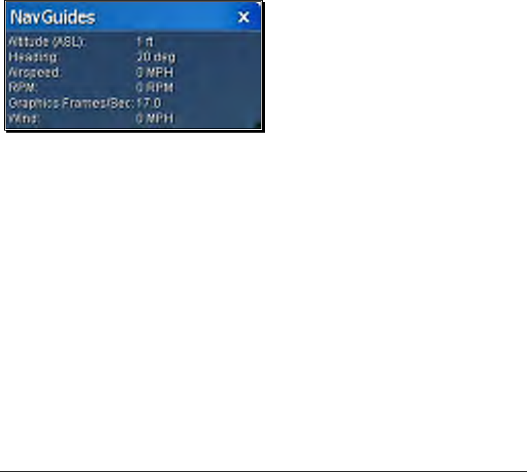
• NavGuides™- Using the NavGuides, you can display a variety of heads-up
on-screen informational displays. Options range from altitude and airspeed to
aircraft heading and engine rpm’s. This feature improves your ability to “see”
what is going on in your virtual world.
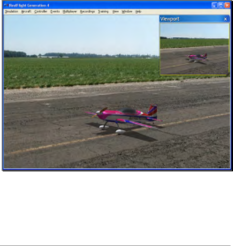
• Viewport- You can open up a picture-in-picture display and treat it as an
independent “window on the world”. You can individually adjust each the
viewport’s vantage point, zoom level, and direction of view.
• Multiplayer-You can fly with up to seven additional RealFlight G4 owners in
competitions, or just for the thrill of flying with one another. This feature can
also be used to learn new maneuvers from pilots across the street or around
the world.
• Events- Compete solo, or fly with up to seven additional RealFlight G4
owners in a variety of Events such as: Limbo, Spot Landing, Free Style, Auto
rotation and Pylon Racing.
• Launcher- RealFlight G4’s Launcher allows for easy one-click access to
program upgrades, online registration, and technical support.
• Animated control surfaces and retracts—Control surfaces, retracts,
propellers, and rotor blades move for added realism.
• Aircraft exhaust/smoke-You can control the color, density, ‘hang time’, and
other parameters related to airplane and helicopter smoke and exhaust.
• Streamers- Add streamers to any aircraft, to any location, in any color. Watch
as they corkscrew behind the airplane during a roll, or react to the wind and
the propwash.
• Flight Failures- RealFlight can simulate many common flight failures (radio
interference, stuck servos, engine failures, etc.). Use this feature to prepare for
emergencies at the field.
• Fully editable aircraft paint/decal schemes- Create customize trim
schemes for your aircraft. (To design your own paint scheme, you must use a
third-party program that edits “.tga” files.)
• Extensive Help materials- RealFlight G4 features extensive online tool tips
and diagrams, a detailed manual and technical support to enhance your
enjoyment of the program.
How to read this manual

6
RealFlight G4 is a menu driven simulator which allows you to make quick changes
without having to reload the simulator each time. This manual will break out each
main menu to its own chapter. This allows you to quickly find information on features
and functions by the related menus.
Along with this manual, a large RealFlight community is available online to help and
discuss with each RealFlight fan. This online support, in the form of a forum, can be
found at:
http://www.knifeedge.com/forums/

7
Before You Begin
To get the most out of RealFlight G4, it helps to understand how to get the most
out of your computer first.
ealFlight Generation 4 is designed to work on a large variety of computer
hardware. Similar to a car, if you want to go faster, you need a bigger engine.
The same holds true with RealFlight. You’ll be able to enjoy the simulator on
most modern computers, but having the most update to date software for
your computer will greatly increase your enjoyment.
System Requirements
You will find the suggested system requirements for the RealFlight G4 R/C Flight
Simulator listed below. The minimum system requirements below are the bare
minimum PC configuration for installing RealFlight G4. Meeting the minimum
requirements will allow you to enjoy G4. However, in order to take complete
advantage of the many features and functions offered by G4, you should have a
computer at, or near, the specifications as specified in the optimum system
requirements.
Minimum Recommended System-
- Some graphical features may be disabled
- Aerodynamic Calculations will still be high-quality
Windows* 98SE, ME, 2000, XP or Vista™
Intel Pentium 1.0GHz or equivalent
512 MB RAM
Chapte
r
2
R

8
3 GB Hard Drive Space
3D Accelerated Video with:
- 32 MB Dedicated Video Memory
- Full DirectX 9 compliant (Pixel Shader 1.4 support)
Optimal System
- For best graphical performance
Dual Core 2.4GHz CPU
2 GB RAM
3D Accelerated Video with:
- 256 MB dedicated video memory
- Pixel Shader 2.0 support
Multiplayer Requirements
• 56.6 Kbps (or faster) modem or LAN connection
Video and Sound Cards
In order to achieve optimum performance and the best flying experience in RealFlight,
there are two important components of your computer that deserve special attention:
the video and sound cards.
RealFlight G4 has undergone countless hours of compatibility testing and evaluation.
As such, this software will adequately function with a variety of video cards- ranging
from yesterday’s favorites to tomorrow’s hits.
While RealFlight works well on a wide variety of hardware configurations, it offers
many features and functions that are designed to take particular advantage of the latest
video technology. If you have an older computer, or a newer computer with a lower-
end video card, you may want to consider purchasing a new video card to take
advantage of these features and functions. This moderately priced upgrade can vastly

9
enhance your enjoyment of RealFlight. Aside from increasing your satisfaction with
G4, a new video card will also work with many other games or simulators, improving
their performance as well.
For a list of the video cards that have been tested by our staff, please visit:
http://www.gpsoftware.com/
While not as important as the video card, upgrading your sound card may also improve
your satisfaction with RealFlight. This is especially true if your computer uses an on-
board sound card (a sound card affixed to the motherboard).
Getting the Most out of RealFlight
We think you’ll agree that RealFlight offers the finest set of instructions and practice
tools of any R/C simulator suited for both beginners and experienced pilots. Great
Planes and Knife Edge Software are committed to the continual improvement of our
products. When using the software, you should keep two things in mind.
First, similar to other pursuits, what you get out of RealFlight depends upon what you
put in. Mastering radio control requires a great deal of patience and practice. If you
crash an aircraft in the simulation, take it very seriously. Crashing an actual R/C
aircraft can cost you a lot of time and money. Try to examine what you did incorrectly,
using the experience to avoid making the same mistake again.
Secondly, while the simulator is quite realistic and will assist you in learning many of the
skills necessary to become a proficient pilot, there is no substitute for actual flying time
at the field. A simulation can be a wonderful practice tool. However, no simulator, no
matter how realistic, can completely replace a qualified, experienced, human flight
instructor. If you are new to R/C, you should never attempt to fly a real aircraft
without the supervision of a qualified instructor, no matter how accomplished you are
on the simulator.

11
Getting Started
A brief overview and assistance to help start you on your R/C adventure.
his chapter covers the installation procedure for RealFlight
G4, describes the basics of running the program, and introduces you to some
of RealFlight’s frequently used features.
The first section, Installing RealFlight G4, offers a step-by-step approach to the
installation procedure for both the program software and the controller.
The second section, Exploring RealFlight G4, offers a brief tour of the RealFlight G4
program. You'll learn how to perform some basic functions, such as selecting the
aircraft you wish to fly, performing simple edits to the flying field, manipulating
viewports, and using RealFlight’s Virtual Flight Instruction feature.
This chapter only touches briefly on some of RealFlight G4’s features. We strongly
suggest that you also read the subsequent chapters, which describe the various features
in comprehensive detail.
Installing RealFlight G4
The RealFlight G4 InterLink Elite controller has several different modes of operation.
By itself, it serves as a realistic ‘stand alone’ controller or joystick. Alternatively, it has a
built-in interface that lets you use your own R/C transmitter to control RealFlight G4.
The final mode of operation combines the InterLink Elite’s ability to serve as a
controller and an interface simultaneously.
Chapte
r
3
T

12
The USB InterLink Elite Controller-
To install RealFlight G4 using the InterLink Elite controller, follow the instructions in
this chapter.
Regardless of whether you plan to use the InterLink Elite controller by itself, or with
your own R/C radio to control RealFlight, follow the instructions on Program
Installation in the next section.
Program Installation-
RealFlight Generation 4 features a simple, one-step installation process. There are,
however, further steps that must be followed prior to running the program for the first
time. This section will explain how to install the RealFlight G4 software and hardware.
Upon completion of this section, you should be able to fly the aircraft on your PC.
The InterLink Elite’s built-in transmitter interface also allows you to use your own R/C
transmitter to control RealFlight G4 should you opt to do so. To activate the interface
adapter, you will first need to follow the instructions in the section below. This section,
will explain the methodology of using the transmitter interface option in the InterLink
Elite controller.
Update Drivers-
Before you begin installation, we strongly suggest that you update the drivers
for both the sound and video cards on your PC. A driver is a software
program that your computer uses to control hardware devices. Each card has
its own respective driver. Most problems with installing and using RealFlight,
as well as many other programs that use DirectX, arise from using outdated
video and/or sound card drivers.
If you are not sure how to update your drivers, you can find instructions in
article Q01-1038, Locating and installing drivers, at

13
http://www.gpsoftware.com/kb/q01-1038.htm. This support article will take
you through the process step-by-step, and has links to driver download sites
for most manufacturers.
Installing the Software-
After you have completed installation of the new video and sound card drivers,
you are now ready to install RealFlight G4.
1. Before installing the software, make sure to close any applications that
you are running. This includes virus scanning software and other
similar applications.
2. Insert Disc 1 (One) into the appropriate CD-ROM drive.
3. If Auto-Play is active, setup will begin automatically when the CD-
ROM drive is closed. Simply click the Install button when prompted.
If Auto-Play is not active, click Start on the task bar. Next, click Run.
In the dialog box that appears, type ‘d:\setup’ (assuming that ‘d’ is
your CD-ROM drive) and click OK.
Follow the on-screen instructions to complete the setup procedure. When
prompted, remove Disc 1 (One) and insert Disc 2 (Two). Following the on-
screen prompt, remove Disc 2 (Two) and insert Disc 3 (Three). Following
the on-screen prompt once again, remove Disc 3 (Three) and insert Disc 4
(Four). Upon completion of the installation, click OK.
Installing or Updating DirectX-
1. RealFlight will ask if you wish to install DirectX 9 on your PC. It is
important that your PC utilizes DirectX 9.0c or later. Click OK to
proceed to the DirectX License Agreement.
2. Click "I accept the license agreement" to install DirectX 9.0c.
Alternatively, if you do not wish to update DirectX at this time, click
Cancel.
3. If you have opted to accept the license agreement, click Next to
proceed with the installation. DirectX will install the necessary files to
update your PC.
4. When prompted, click Finish. Your PC will power down and then
restart once again.
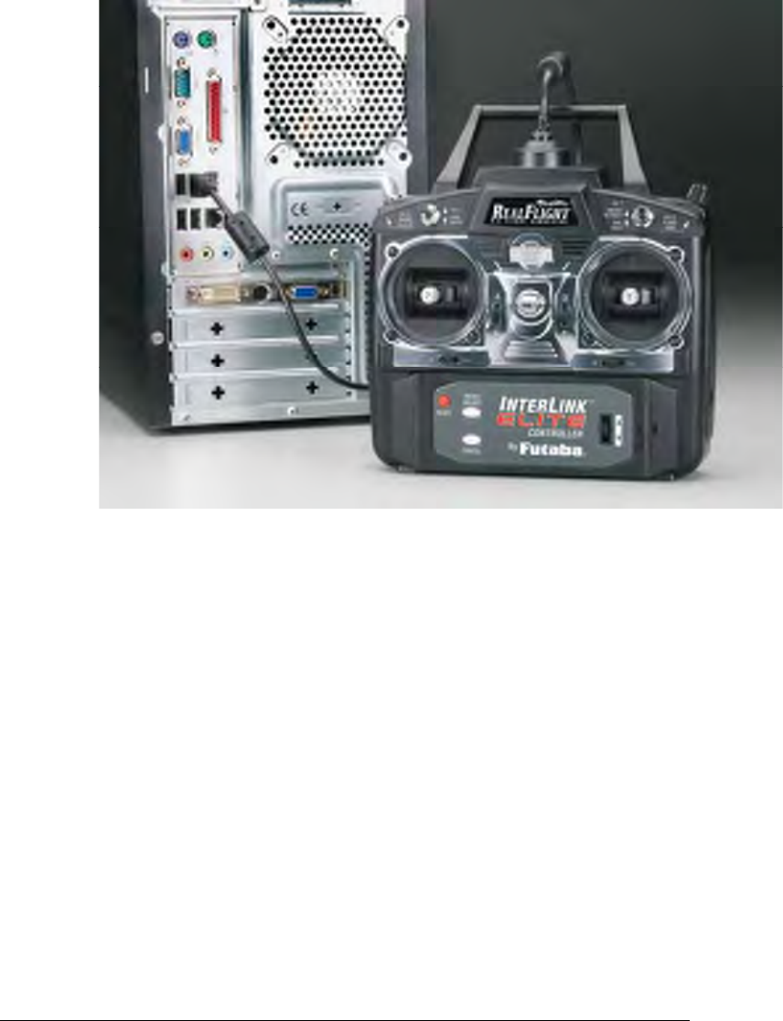
Connect the InterLink Elite Controller-
The InterLink Elite controller uses the USB (Universal Serial Bus) port, so
there is little to do in the way of setup.
14
1. With the software installation procedure complete, firmly plug the
InterLink Elite controller into one of the unused USB ports on the PC.
Because the controller is hot swappable, you do not have to shut the
PC down to plug the controller in.
2. Shortly after plugging in the InterLink Elite controller, a dialog box
should appear on the screen indicating that Windows has located a
new device and will then automatically install the necessary drivers.
Note: It is possible that Windows will need to install the appropriate files for
the InterLink Elite controller to function properly. Please have your Windows
CD-ROM available in case it is required.
Starting RealFlight Generation 4-
1. Double-click the RealFlight G4 Launcher located on your desktop.
2. Type in your name, software serial number and the InterLink Elite
controller serial number in the appropriate location. Please be sure
to enter the numbers exactly as they appear. Failure to enter the serial
numbers correctly will not allow you to proceed to the next step. If
the serial numbers are entered properly, the OK button will become
active.

15
Insert Photos and Captions here…. CD-ROM and InterLink Elite
controller.
3. Click OK. The RealFlight G4 Launcher will appear. Click Run
RealFlight. RealFlight G4 will start with a default aircraft and default
flying site.
Note: The procedure above will allow you to pilot the RealFlight aircraft using
the InterLink Elite controller. The InterLink Elite controller may also be used
as an interface unit, allowing you to pilot the aircraft with your actual R/C
transmitter. For information on how to do so, please refer to the section
entitled Using Your Own R/C Radio which follows.
Using Your Own R/C Radio
Follow these instructions if you intend to use your own R/C transmitter to control
RealFlight G4. If you do not want to use your own transmitter, skip this section.
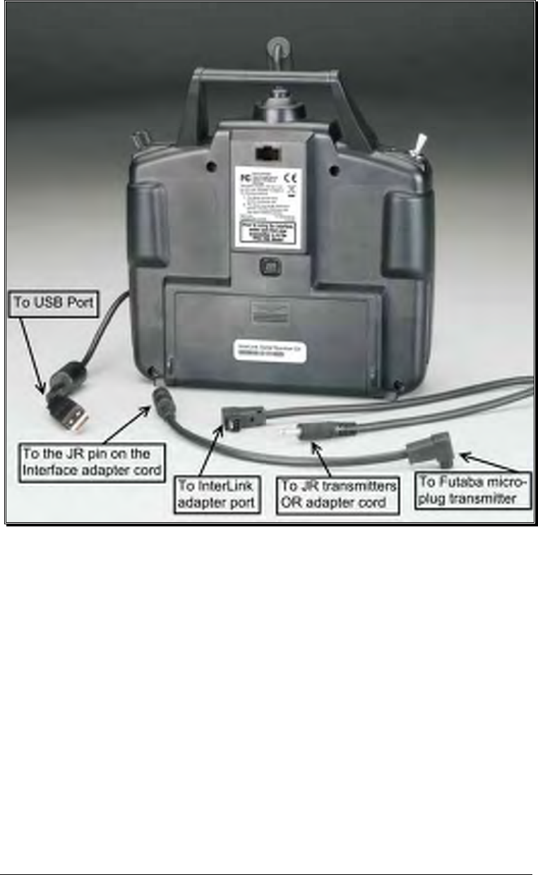
Connecting Your Transmitter-
You can use your R/C transmitter to control RealFlight G4 by connecting it to the
InterLink Elite controller, ‘buddy box’ style (see diagrams). RealFlight G4 includes
several adapter cables used to make the connection to many popular R/C transmitters.
Any changes or modifications not expressly approved by the party responsible for
compliance could void the user's authority to operate the equipment.
NOTE: This equipment has been tested and found to comply with the limits for a Class B
digital device, pursuant to Part 15 of the FCC Rules. These limits are designed to
provide reasonable protection against harmful interference in a residential installation.
This equipment generates, uses and can radiate radio frequency energy and, if not
installed and used in accordance with the instructions, may cause harmful interference to
radio communications. However, there is no guarantee that interference will not occur in
a particular installation. If this equipment does cause harmful interference to radio or
television reception, which can be determined by turning the equipment off and on, the
user is encouraged to try to correct the interference by one or more of the following
measures:
-- Reorient or relocate the receiving antenna.
-- Increase the separation between the equipment and receiver.
-- Connect the equipment into an outlet on a circuit different from that to which the
receiver is connected.
-- Consult the dealer or an experienced radio/TV technician for help.
16
Locate the cable input port on the rear of the InterLink Elite Controller. Plug one end
of the included connector cable into this port. Next, plug the other end of the adapter
cable into the buddy box port (a.k.a. trainer jack) of your transmitter. The procedure
for doing so depends on your transmitter:
• If your transmitter’s buddy box port directly accepts the 1/8” stereo plug, insert
this end directly into the radio. This works for most JR® radios.
• If your transmitter’s buddy box port requires the micro (square) connector, use the
squared adapter cord included with the simulator.
• Some radios (e.g., Airtronics®, Hitec® and older Futaba® transmitters) require the
purchase of an optional adapter cable. This adapter cable is available wherever you
purchased your copy of RealFlight G4.

17
Setup-
After you have connected your transmitter to the InterLink Elite controller, you will
need to perform a brief setup procedure before utilizing it with the simulation.
1. First, make sure that the transmitter is in FM or PPM mode rather than PCM
mode. Refer to the manual for your transmitter if you are unsure how to do
this.
2. If the transmitter did not power up when the interface cord was plugged into it,
turn the power switch on at this time.
3. Next, click the Controller menu and then highlight the Select Controller…
menu item. After a brief delay an option for the InterLink Elite Transmitter x
channel should appear. Choose the InterLink Elite Transmitter X Channel
option.
Exploring RealFlight G4
Now that you have completed the installation of RealFlight G4, it’s time to begin
exploring the program. The following sections will take you on a quick tour of
RealFlight G4’s most popular features, such as selecting an aircraft, choosing alternate
flying locations, customizing the flying sites, and using the training aids instruction.
Along the way, we will show you where to go for help and how to obtain additional
information.
Even if you are familiar with previous versions of the RealFlight software, you should
read this section thoroughly. The features described here are either new or have been
completely revised for G4.
Start the Program-
1. Close all open applications. This includes virus scanning software and other
similar programs.
2. Double-click the RealFlight G4 Launcher located on your desktop.
3. To start the simulation, click the Run RealFlight button.
The program will start using the pre-set defaults -- including pilot perspective, flying
location, and aircraft.
The Main RealFlight Display-
RealFlight G4 is a menu-driven program. As seen in the picture below, a menu bar
appears across the top of the RealFlight screen. The menus contain additional menu
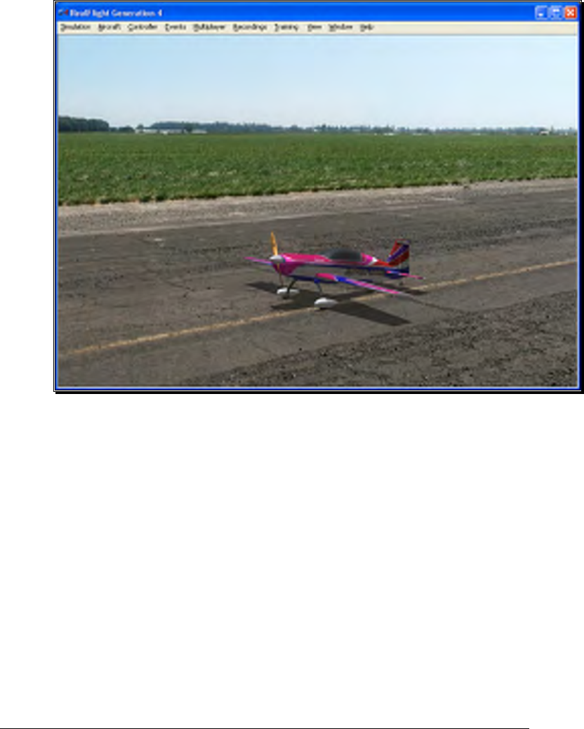
18
items and pull-down lists for the related options of the respective menu. These menus
allow access to the command and control functions for the RealFlight G4 simulation.
Navigating the Menus-
To access the various menu items, simply highlight and click the mouse on the
menu that you would like to view. For example, clicking on the Aircraft menu
activates the sub-menu items for that menu.
The top-level menus found in G4 are as follows:
• Simulation
• Aircraft
• Controller
• Events
• Multiplayer
• Recordings
• Training
19
• View
• Window
• Help
This manual includes a separate chapter for each menu title. Later chapters
describe (in detail) all of the menu items, sub-menus and options.
Please note that it is also possible to access many of the features and functions
of RealFlight Generation 4 using hot keys. Pressing the H key on the
keyboard activates the Keyboard Commands dialog, which summarizes the
available hot keys.
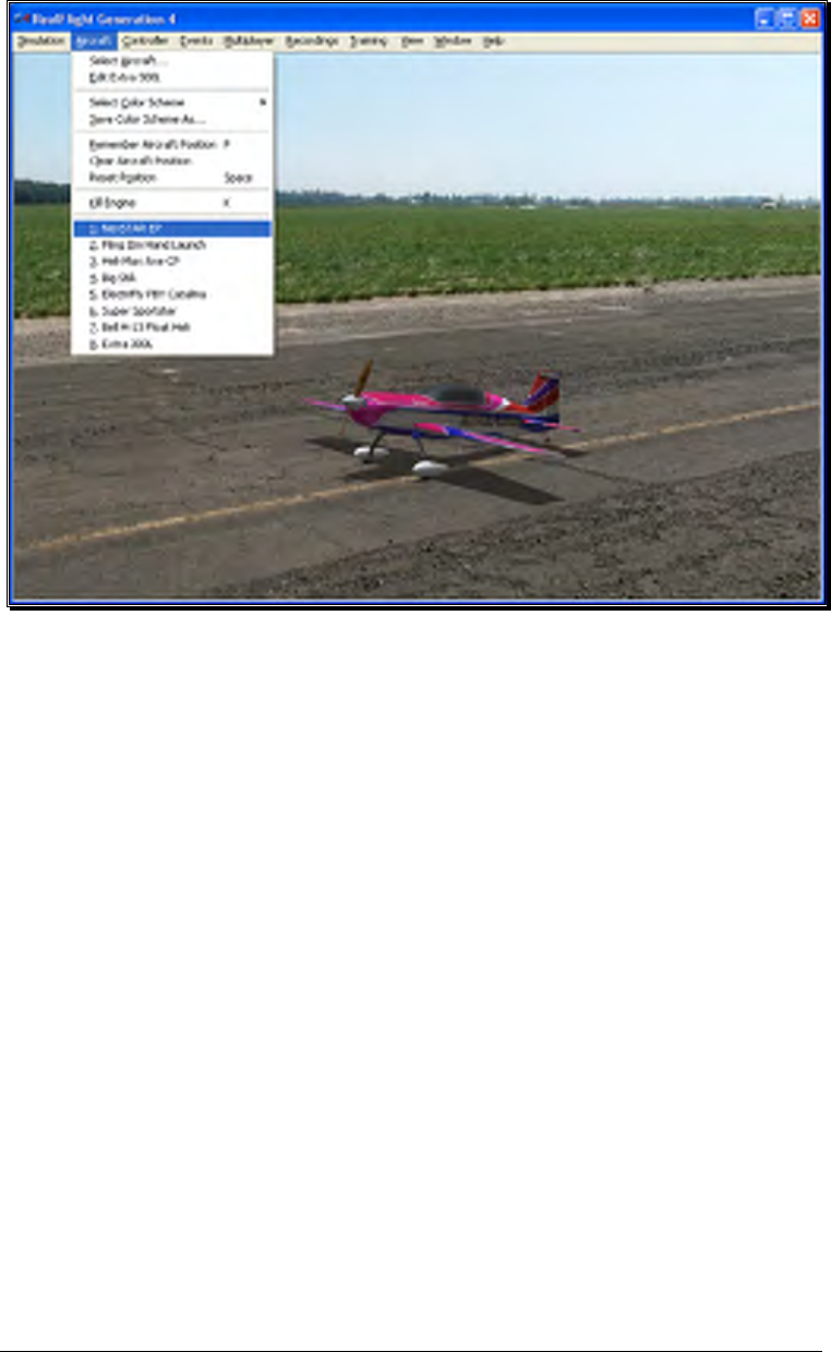
Aircraft Selection-
When you start G4 for the first time, you will be piloting an Extra 300L. This is the
default aircraft for RealFlight G4.
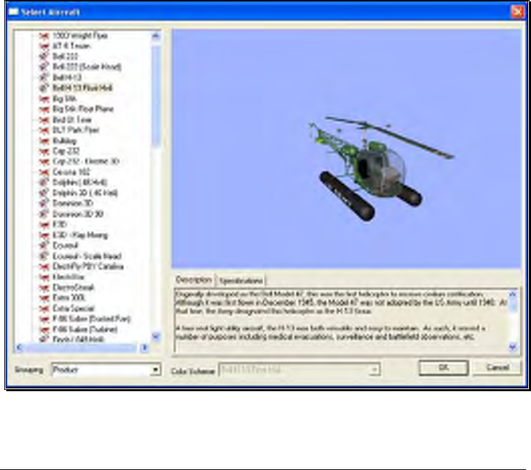
To select a different aircraft, click the Aircraft menu title in the main menu bar. Next,
click the Select Aircraft… menu item found in the drop-down menu. This activates
the Select Aircraft dialog (as shown below), which displays a list of available aircraft.

20
Each aircraft available in G4 is listed along the left-hand side. The icon next to each
name differs depending on whether the model is an airplane or a helicopter. To select
an aircraft from the list, click on the desired aircraft. The selected model will now
appear in the ReadySelect™ preview box. Additionally, an aircraft description and
information data will appear in the aircraft information pane, which appears just below
the ReadySelect preview window.
When you are satisfied with your selection, click OK to return to the simulator using
the new aircraft selection.
Complete information pertaining to the Select Aircraft… menu item is available in a
later chapter of this manual.
Alternatively, you may use the InterLink Elite controller to change aircraft selections.
Simply press the Menu/Select button located on the front of the InterLink Elite
controller. This will bring forth the QuickSelect tabs on the left side of the computer
screen and the aircraft selection tab, represented as an airplane icon, should be the
highlighted tab. Press the Menu/Select button once again to bring up the Aircraft
Selection dialog box. Move the Data Lever, found on the lower right side of the
InterLink Elite controller, up or down to view the available aircraft. The [+] (plus)
indicates that there is another expansion level (selection) available to you, press the
Menu/Select button to access the items located within this folder.
To select an aircraft, simply highlight the name and press the Menu/Select button.
You will return to the simulation using the newly selected aircraft.
If you wish to exit the Aircraft Selection screen without making any changes, simply
press the Reset button on the InterLink Elite.
Aircraft Most Recently Used List (MRU)-
If you have selected alternative aircraft previously, you will note that these aircraft
appear on a list in the Aircraft menu, as shown below. This list is at the very bottom of
the menu. This list is commonly referred to as a Most Recently Used, or MRU list. It
is limited to the eight most recently used aircraft. If you wish to fly one of the aircraft
from this list, simply click on the name of the aircraft in the MRU list.
21
Airport Selection-
Changing flying sites uses a process similar to the process used to select an aircraft. To
select a new flying location, click the Simulation menu located in the header. Next,
click the Select Airport… menu item found in the drop-down menu. This opens the
Select Airport dialog, which lists the available flying locations. Select either the
Archipelago, PhotoFields, or Sierra Nevada location.
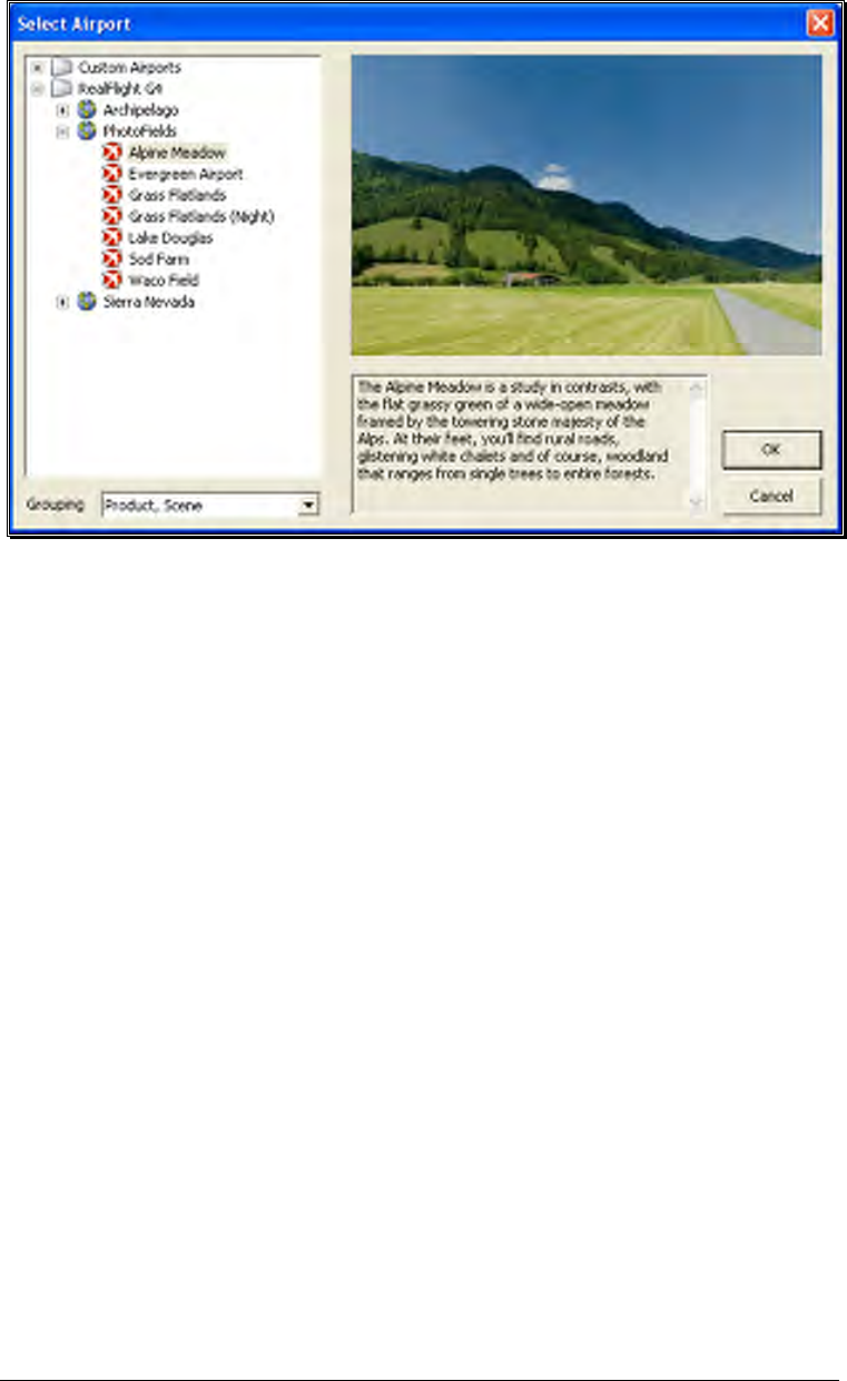
22
Each airport is preceded with a [+] (plus) and an icon. The [+] (plus) indicates that
another expansion level (selection) is available to you. To access the complete list of
airports for a respective location, either click the [+] (plus) or double-click on the
desired airport. For example, clicking the [+] (plus) on the PhotoField folder reveals all
of the PhotoField flying sites available to you.
To select an airport from the list, click on the desired airport. The selected airport will
now appear in the preview box. Additionally, an airport description and informational
data will appear in the information pane, which appears just below the preview window.
When you are satisfied with your selection, click OK to return to the simulator using
the new airport selection. Navigating the Airport Selection menu using the
QuickSelect feature is almost identical to the process mentioned above for selecting an
alternative aircraft. Only this time, you will select the airport selection menu, which is
represented by a runway icon. With the QuickSelect tabs visible on the computer
screen, move the Data Lever down one time. This should highlight the runway icon.
Press the Menu/Select button to bring forth the available flying sites. Using the same
method, as described previously for aircraft, select the new airport and press the
Menu/Select button to return to the simulation using this new flying site.
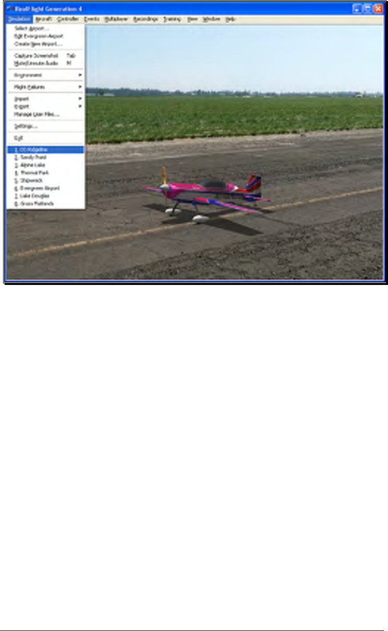
Airport Most Recently Used List (MRU)-
If you have previously selected an alternative flying location, it will appear on a list in
the Simulation menu. This list is at the very bottom of the menu and is commonly
referred to as a Most Recently Used, or MRU list. It is limited to the eight most
recently selected locations. If you wish to fly at one of these locations simply click on
the respective location in the MRU list to load it into the simulation.
23
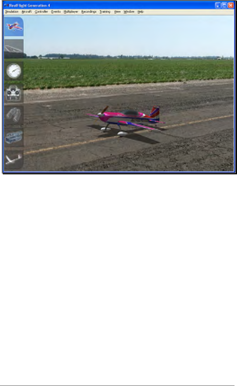
QuickSelect Tabs-
RealFlight G4 offers a revolutionary methodology in which to access many features
and functions quickly and easily without ever touching the keyboard or mouse. There
are seven main areas of access available through the QuickSelect tabs. They are as
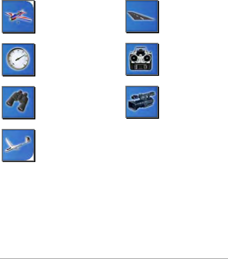
follows: Airplane Selection, Flying Site Selection, NavGuides, On-Screen Radio,
Binocular view, Viewports and Variometer.
To access any of the QuickSelect tabs, press the Menu/Select button on the
InterLink Elite controller. This will bring forth the available options on the left side of
the computer screen. Move the Data Lever up or down to cycle through the
QuickSelect tabs. The highlighted tab is the item that is active. To access the active tab,
press the Menu/Select button.
24
For additional information on how to use the QuickSelect tabs, please refer to the
information contained in the section entitled QuickSelect- on page 35.
Some Common Tasks-
• The easiest method of resetting your aircraft to its original takeoff position is to
press the reset button located on the front of the InterLink Elite controller.
Alternatively, you can reset the aircraft by pressing the space bar on the keyboard,
or by selecting the Reset Position menu item, which is located in the Aircraft menu.
• If your aircraft is equipped with smoke, the two-position switch located on the
right side of your InterLink Elite controller will generally be utilized to activate this
feature.
• To magnify the view or zoom in on an aircraft, press the [+] (plus) key on the
number pad of the keyboard. Alternatively, you may use menu commands to
zoom in. To do so, click on the View menu and then click on the Zoom In menu
item. Each time the [+] (plus) key or the Zoom In menu item are pressed or
selected, the view will increase incrementally.
• To reduce the magnification, or zoom out of the current view press the [–]
(minus) key on the number pad of the keyboard. Alternatively, you may use
menu commands to zoom out. To do so, click on the View menu and then click
25
on the Zoom Out menu item. Every time you press [-] (minus) key or select and
press the Zoom Out menu item, the view will decrease incrementally.
• To reset the view to the default magnification, press the Backspace on the
keyboard.
Creating a Viewport-
RealFlight allows you to create an additional picture-in-picture viewport. Once you
create a new viewport, you may resize or reposition it by dragging with the mouse.
You can also fully adjust all of the viewport’s properties independently of the main
window. The viewports may be utilized for a variety of applications, such as changing
the viewing perspective of your simulation.
To create a new viewport, click the Window menu title followed by the Create New
View menu item. Alternatively, you may also press the ‘4’ key on the keyboard to
create an additional viewport.
To change the vantage point within the viewport, press the ‘C’ key on the keyboard.
The ‘C’ toggles through the various camera modes; the first of which is the cockpit or
pilot’s perspective. The second is chase view, and the last mode is the fixed viewpoint,
or what you would see if you were standing at the side of the runway. Please note:
depending upon the flying site selected, some of these viewing options may not be
applicable.
26
The Window chapter of this manual contains a thorough explanation of the viewports
and the viewport options.
Using Gadgets-
The RealFlight G4 software includes several gadgets that may be displayed in the main
window when running the software. A gadget is an on-screen display that provides
helpful information or allows you to access to a variety of RealFlight features and
functions.
For example, the NavGuides gadget displays continuously updated information
relating to your aircraft’s altitude, airspeed, directional heading, and other flight
parameters. To display the NavGuides gadget, click the Window menu title followed
by the Gadgets menu item. Next, select the NavGuides gadget located in the drop-
down menu. You may also access the NavGuides gadget by pressing the numerical ‘1’
key on your keyboard. Alternatively, you may activate the NavGuides gadget through
the QuickSelect tabs. To do so, press the Menu/Select button on the InterLink Elite
controller. Next, move the Data Lever downward twice. Finally, press the
Mode/Select button to activate the NavGuides.
When you select NavGuides, you should see the NavGuides gadget appear on your
screen:
As discussed previously, you can customize the gadgets for personal preference. For
complete information on how to do so, please refer to the chapter pertaining to the
Window menu options.
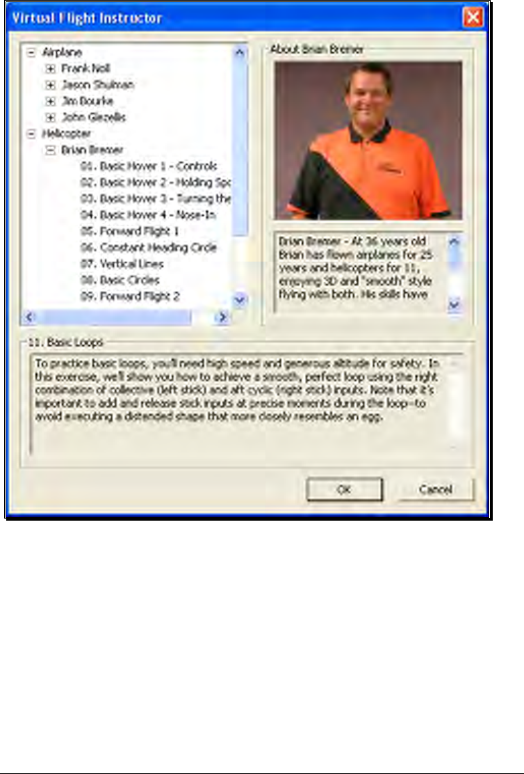
Virtual Flight Instruction-
RealFlight G4 includes a variety of basic, intermediate and advanced pre-recorded
maneuver lessons for helicopter and airplane pilots. A professional, award-winning
R/C pilot talks you through every facet of the maneuver. You can use the Virtual
Flight Instruction to learn new maneuvers as well as to perfect those maneuvers that
you already know.
To activate the pre-recorded maneuvers, click on the Training menu followed by the
Virtual Flight Instruction… menu item. Alternatively, press the ‘V’ key on your
computer’s keyboard. Either method brings forth two options: airplane and
helicopter, each proceeded by a [+] (plus) symbol. If you wish to practice an airplane-
27
related maneuver, click the [+] (plus) near the airplane. Alternatively, you may also
double-click the word itself (e.g., airplane). This brings up the pilot selections. To
select amongst the pilots, click the [+] (plus) which precedes their name. Alternatively,
you may double-click the pilot’s name.
To select a maneuver, double-click the name of the maneuver itself. Alternatively,
highlight the name of the maneuver by clicking on it, then select OK. After you have
selected a maneuver, click OK to proceed. RealFlight G4 will automatically load the
default airport and then start the VFI recording.
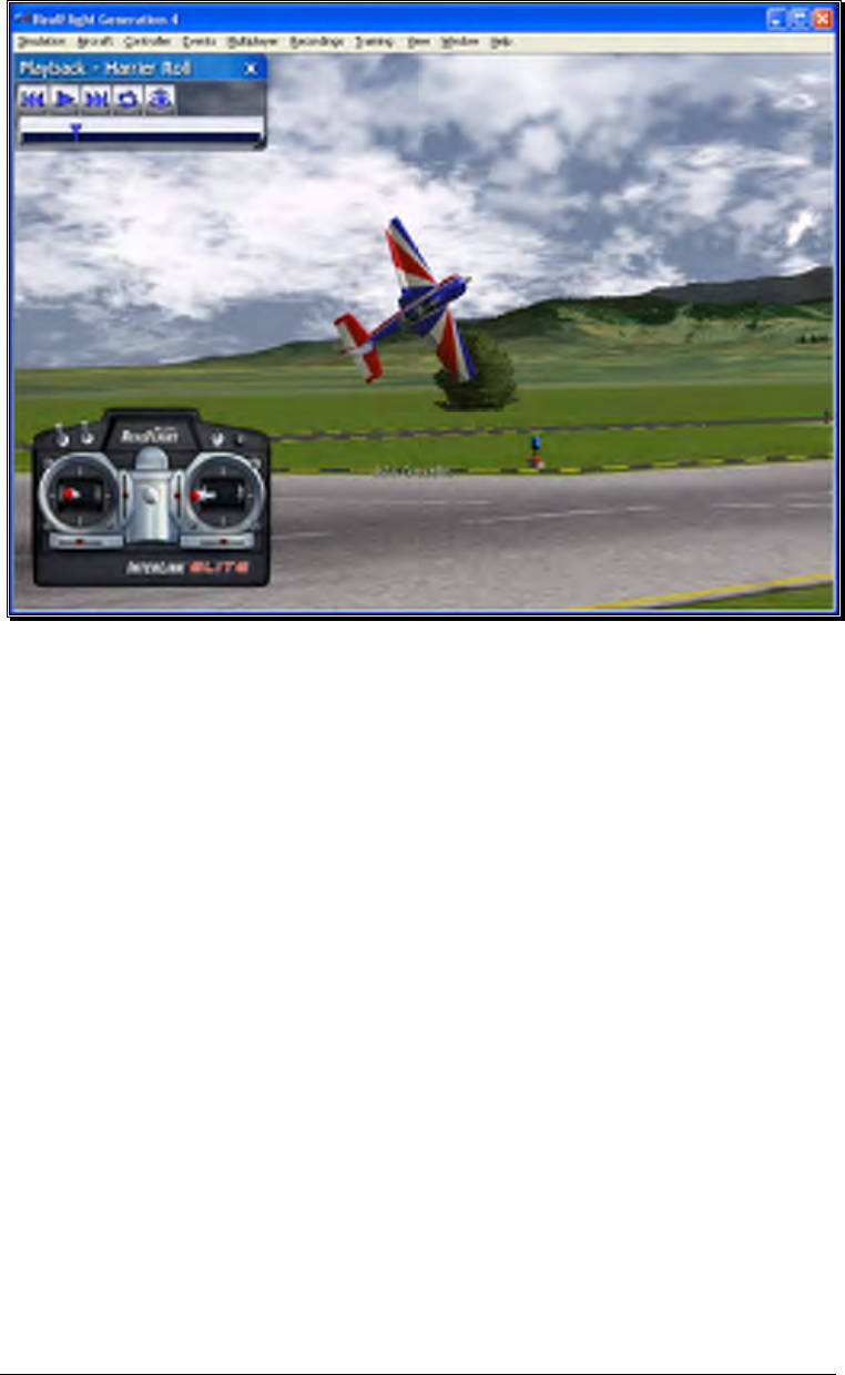
Once the VFI starts, you will see the instructor’s aircraft fly the maneuver and hear the
instructor’s voice explaining how it’s done. As depicted below, you can also watch the
instructor’s actual stick movements using the on-screen, digitized R/C radio.
28
You can even fly your own aircraft next to the instructor’s! This allows you to mimic
the inputs and aircraft reaction simultaneously. To simultaneously watch your aircraft
and the instructor’s, create an additional viewport focused on your aircraft. The main
window will show the instructor’s aircraft and the on-screen radio will show the
instructor’s stick movements. The newly created viewport will show your aircraft.
RealFlight Trainers-
RealFlight G4 includes several training aids to help learn the basics of taking off and
landing an airplane. Obviously, mastering these skills is essential to the success of your
entry into radio control flight.
The Takeoff training feature, as the name suggests, is designed to enable pilots of all
skill levels to perfect their takeoffs.
To select the Takeoff training feature, click on the Training menu title followed by the
Takeoff Trainer… menu item. The Takeoff Trainer will start using the default
settings. If, however, you wish to alter any of the settings, click on the Trainer menu
title. For additional information pertaining to these settings, please refer to the section
entitled Takeoff Trainer on page 200 in this manual.
29
The Landing Trainer feature, is designed to enhance a pilot’s landing skills. As with
full-scale aircraft, it is imperative that an R/C pilot be well-versed in the proper
technique of landing their aircraft in various conditions. Failure to land an aircraft
properly may result in a damaged aircraft…or perhaps even destroy it entirely.
To select the Landing Trainer feature, click on the Training menu title followed by the
Landing Trainer… menu item. The Landing Trainer will begin with the aircraft in a
pre-determined position using its default settings. If, however, you wish to alter any of
the settings, click on the Trainer menu title. For additional information pertaining to
these settings, please refer to the section entitled Landing Trainer located on page 205
in this manual.
30
Airport Editing-
RealFlight G4 offers the most powerful, flexible flying site editor ever produced on an
R/C simulation. G4’s FlexiField™ editor allows you to completely customize virtually
every aspect of your flying sites.

31
You can add, remove, change orientation, or resize virtually every aspect of your flying
site. You can alter the position and orientation of the ground objects (such as runways)
that ‘snap’ to the terrain—you can even have a runway running up a hill! It’s even
possible to control lighting, terrain, clouds, fog/haze, and much more. FlexiField
provides you with almost unlimited freedom to create the flying environment you want.
Moreover, when you’ve created an airport, you can share it with other RealFlight G4
users.
To learn more about the FlexiField flying site editor, please refer to the section titled
Edit Current Airport… on page 40.
Where to Go From Here
The examples in this chapter only scratch the surface of RealFlight G4’s unparalleled
capabilities. You can fly with others over the internet, fly with a friend using
MultiMode on the same PC, try your hand at a limbo event, customize your aircraft’s
flight parameters, and much, much more! We encourage you to explore RealFlight G4
using some of the methods below.

32
• Browse through the menus. Many of the menus are self-explanatory, providing
you with a more thorough look at the software. If you’re adventuresome, dive
right in and start making modifications to an aircraft or a flying site! It’s a great
way to learn more about what makes G4 tick!
• If you’d like to learn more about a particular menu or item, look it up in the table
of contents.
• If you would like RealFlight G4 to perform a certain function but cannot locate the
appropriate command, check the index.
• Use the Help facilities in RealFlight’s Help menu.
• Talk to other RealFlight users, at www.knifeedge.com.

33
The InterLink Elite
Controller
The InterLink Elite is your all-access pass to the RealFlight world.
he R/C transmitter is a key component in all types of R/C flying. This unique
method of control is part of what separates R/C from every other type of
aviation. Consequently, a realistically simulated transmitter is an important key
to an authentic simulation of the R/C experience.
With this in mind, we at Great Planes are proud to offer our revolutionary USB
InterLink Elite (U.S. Patent #6,842,804 and #7,010,628) controller, made by Futaba.
The InterLink Elite controller was designed from the ground up to meet the needs of
the R/C purist. We believe that no other R/C simulator control method goes farther
to enrich your R/C simulator experience.
Chapte
r
4
T

34
Features of the InterLink Elite Controller-
• USB compatibility and convenience. The InterLink Elite offers the “plug and
play” convenience, “hot pluggable” installation and removal, as well as the high-
speed digital performance made possible by Universal Serial Bus (USB) technology.
• High quality “mockup” transmitter. Use the InterLink Elite controller by itself as a
pseudo R/C transmitter, with the controls you expect in a standard 8-channel radio.
The mockup transmitter features two 2-position switches, one 3-position switch, a
rotary knob, knurled control sticks with adjustable length and a push-button reset.
• Built-in Transmitter interface. If you so choose, you can use your own FM or FM-
compatible R/C transmitter to control RealFlight, using the InterLink Elite
controller’s built-in interface. You can even switch back and forth between the
pseudo controller and your own transmitter! Interface adapter cords are included
for most JR, Futaba and Hitec transmitters.
• Simultaneous interface and controller. The InterLink Elite makes it possible for
two modelers to fly on the same PC, each using his/her own controller to pilot the
aircraft.
• QuickSelect menu controls. With the InterLink Elite, you’re able to make a variety
of common adjustments to the simulator (such as, selecting a different aircraft or
airport.) without having to touch the keyboard and mouse.
• Easy setup and use. Unlike other computer joysticks, in most cases, you do not
even have to calibrate the InterLink Elite controller. Simply plug it in and go!
• Simulate sophisticated computer radios. The InterLink Elite, used in conjunction
with the RealFlight software, allows you to simulate the programmability (mixing,
exponential, etc.) of sophisticated computer radios.
Start Flying!
When you start RealFlight for the first time, the software will automatically detect the
InterLink Elite controller. Simply add throttle and start flying right away.
RealFlight, by default, uses the InterLink Joystick setting. This setting affords G4 the
plug-and-play capability in the simulation. In this mode, the InterLink Joystick allows
the InterLink Elite to control all functions associated with the flight of your aircraft.
The InterLink Elite also allows you to use your own R/C transmitter to control the
RealFlight aircraft. This is referred to as the Transmitter Interface Mode.
35
QuickSelect-
The InterLink Elite also offers QuickSelect buttons located at the bottom of the
controller. These buttons allow you to make simple changes to the simulator without
having to put the controller down and reach for the keyboard and/or mouse. This
makes it convenient to change the current aircraft and airport, or display popular on-
screen gadgets.
To access the QuickSelect tabs, press the Menu/Select button to display a number of
tabs on the left side of the simulator. Use the Up and Down direction on the Data
Lever, located on the lower right side of the controller, to scroll through these options.
Pressing the Menu/Select button again will select the highlighted tab. Pressing the
Cancel button on the InterLink Elite will exit out of the tabs and hide them.
The options available are:
Select Aircraft
NavGuide Gadget
Binocular View
Variometer
Select Airport
Radio Gadget
Viewport
When using the QuickSelect buttons in the Select Aircraft or Select Airport dialog
screen, press Menu/Select to select the current highlighted item. Pressing Cancel on
the InterLink Elite will move you up a level so you can quickly change folders. To exit
out of these dialog screens without making any changes, simply press the Reset button.

36
Look for the icon to the left throughout this manual for suggestions
on when to use the QuickSelect buttons.
37
The Simulation Menu
Allowing access to a variety of simulation-related features, functions and options.
he Simulation menu brings forth a pull-down menu, giving you access to many
simulator related features, such as changing flying sites, or importing and
exporting RealFlight files.
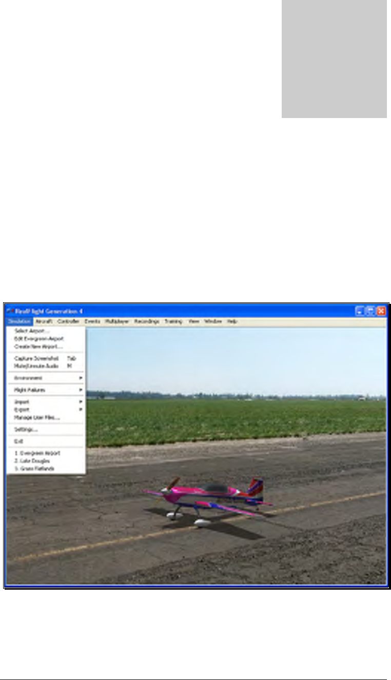
Clicking the Simulation menu will bring forth a screen that looks similar to the
following screen shot.
Menu items that are available are:
• Select Airport...
• Edit Airport Name
Chapte
r
5
T
38
• Create New Airport…
• Capture Screenshot
• Mute Audio
• Environment
• Flight Failures
• Import
• Export
• Manage User Files
• Settings
• Exit
• Airport MRU
Select Airport…
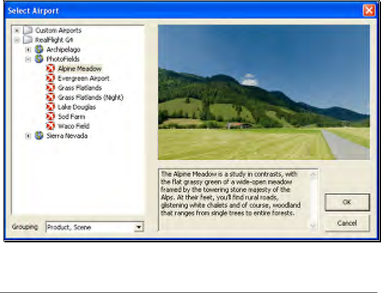
When you click on Select Airport… the following dialog appears:

39
This dialog lets you choose the flying site that you wish to use for your flight. Each
location offers its own unique characteristics and challenges.
The list on the left of the dialog box displays all of the flying sites available to you. If
you have created any flying sites, those sites will also be visible here.
The flying sites are listed in files and folders in accordance with the software from
which they were loaded. If, for example, you have installed Expansion Pack 2, the sites
from this disk will be listed, alphabetically, beneath the Expansion Pack 2 folder. You
can change how the airports are organized by clicking on the Grouping drop-down
and select another grouping option. The options are:
Product, Scene: As explained above, airports are first grouped into folders by the
product in which they are contained. Within each group they are then grouped further
by scene.
Product: Airports are grouped by product alone.
Scene: Airports are grouped by scene alone.
None: Airports are not grouped into folders at all. Rather, they are listed alphabetically.
Click the [+] (plus) or the [-] (minus) symbol to reveal or hide the respective airports
within these folders. To select an airport, click on the name of the airport at which you
wish to fly.
The rotating image on the right side of the screen provides you with a preview of what
to expect at the desired location. The dialog box below the terrain map contains a
description and pertinent information regarding the highlighted airport.
Have some fun while you’re in the Select Airport dialog. Using the mouse, click and
drag the preview screen to point the camera angle to your choosing. To resume
rotating automatically, right-click the preview screen.
When you are satisfied with your selection, click OK to return to your flight using the
new airport selection.
The Cancel button will return you to the simulation at the previously selected flying site.
Change airports simply by using the InterLink Elite. Press the
Menu/Select button, then, using the Data Lever, move down one
tab and press the Menu/Select button again. This will bring up the
Select Airport dialog window. You can continue using the
QuickSelect buttons in this dialog to select a new airport, or press
Reset to resume flying without making any changes.

40
Movement Modes
If applicable to the respective airports, Generation 4’s Movement Modes allow you to
explore the scenery without an aircraft. Movement is not possible at PhotoField
airports.
To select a Movement Mode, press the ‘Q’ key on your keyboard. You can press the
‘Q’ key repeatedly to cycle through the available modes: Walk, Fly or Hover.
Walk mode simulates the effect of you, the pilot, physically walking across the field,
complete with sound effects. The Fly mode allows you to move through the air and
position the camera anywhere that you desire.
Once you have entered the desired Movement Mode, use the ‘W’, ‘S’, ‘A’ and ‘D’ keys
on your keyboard to control the movements. If you wish to increase the speed of your
movement, press and hold the Shift key at the same time you are using the ‘W’, ‘S’, ‘A’
or ‘D’ key.
The mouse wheel controls the angle or height at which you traverse the scenery. To
increase the altitude, roll the wheel away from you. This is known as the Hover Mode.
You may also control the zoom levels during your travels. Press the [+] (plus) key to
Zoom In and the [-] (minus) key to Zoom Out. The Backspace key resets the
zoom level to its default value.
Edit Current Airport…
RealFlight G4 offers unparalleled freedom to edit flying sites. You can add and
remove objects, alter their location, rotate, and even resize items. It is also possible to
alter the atmospheric or lighting conditions at the various flying locations. The first
several times you access the airport editing function, the possibilities might seem
daunting. It will require some getting used to before you are comfortable with this
feature and its related functions. The best way to do so is to simply dive in and
experiment.
To modify the currently selected flying location, click the Simulation menu followed
by the Edit <Current Airport>… menu item, where <Current Airport> is the name
of the airport you have loaded at the moment. This activates RealFlight G4’s
FlexiField flying site editor, with the currently active airport loaded and ready to edit.
41
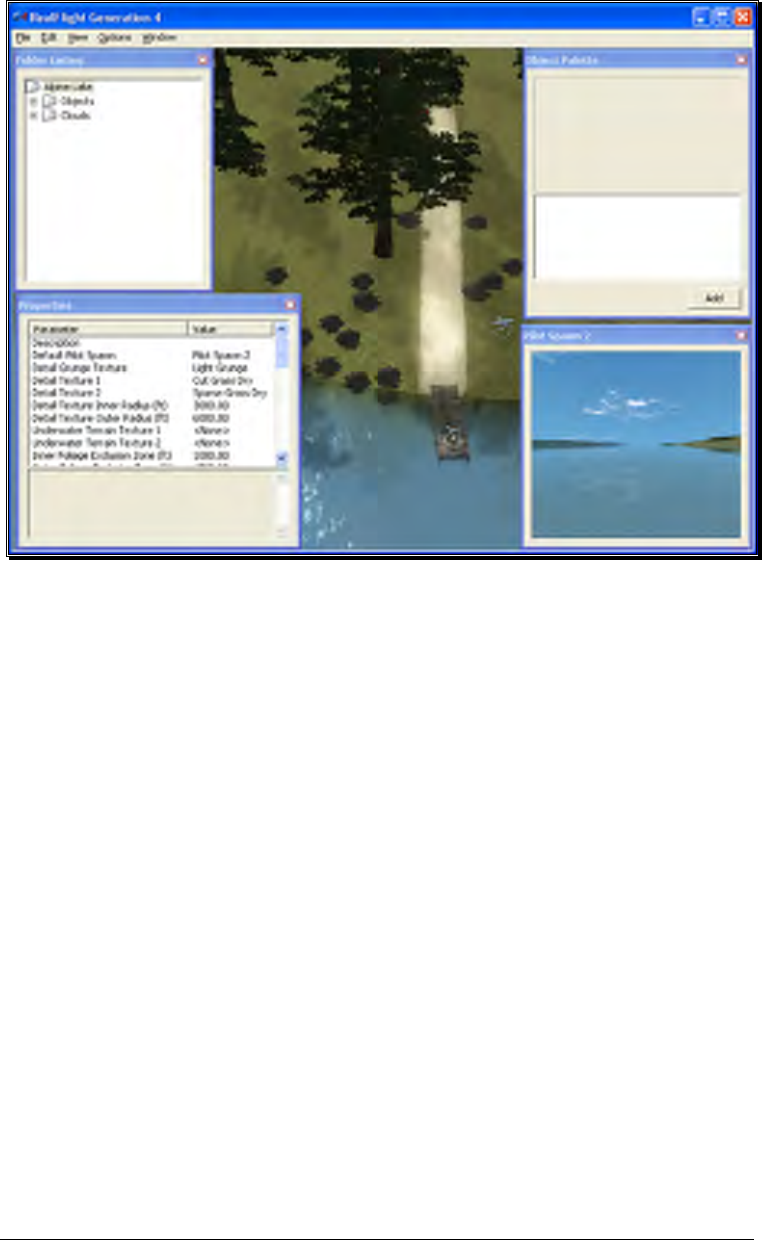
Airport Editor Menus-
Selecting the Edit Current Airport option activates the screen shown above. There are
five menus in the Airport Editor dialog:
• File
• Edit
• View
• Options
• Window
File Menu-
This menu and its menu items are used to manipulate and control the various folders
and related items in the airport editor.
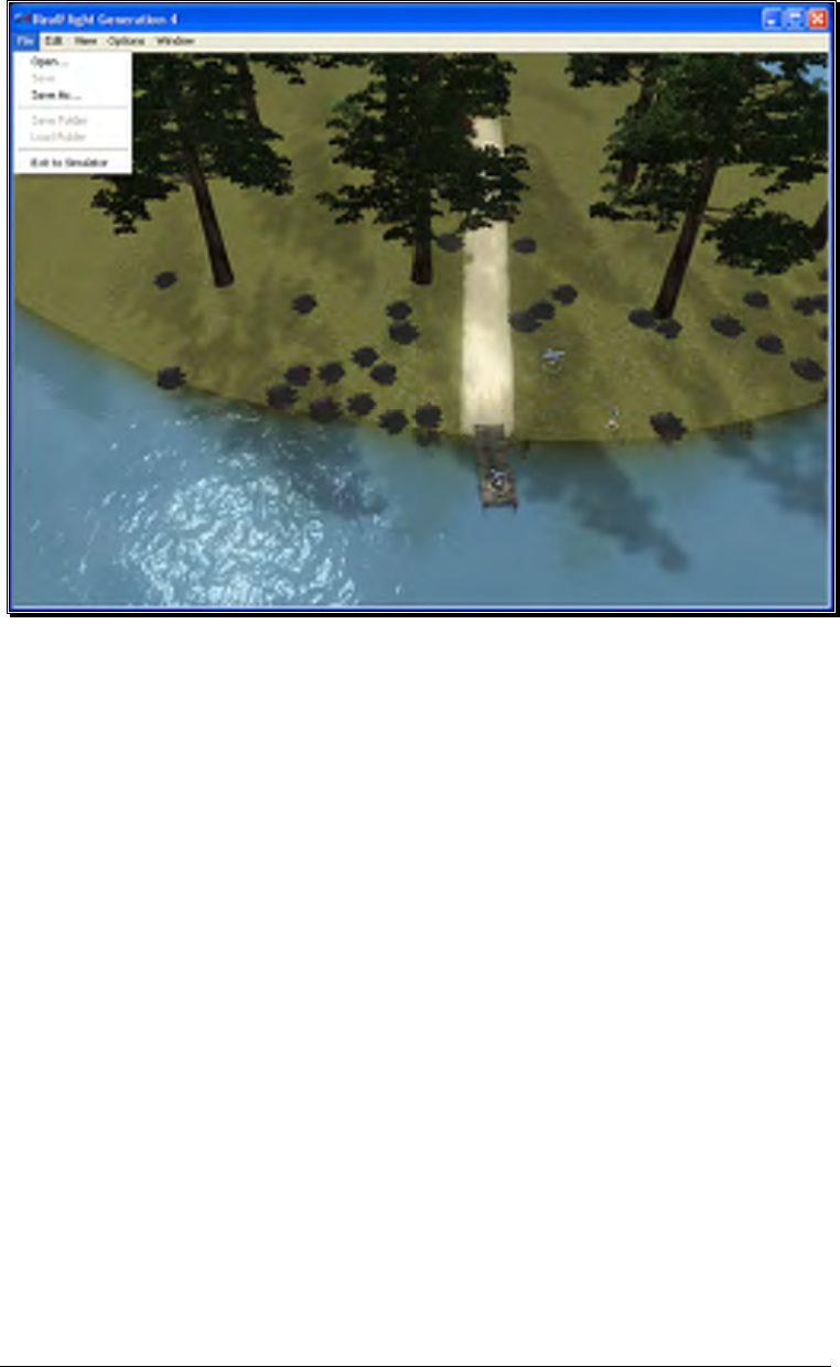
42
Open-
This menu item is used to open existing and edited airports. Selecting this
menu item opens the Select Airport dialog.
Save-
This option becomes active once you have renamed and saved the edited
airport. Prior to doing so this option remains inactive and grayed out.
Save As-
Upon completion of the airport editing, click this menu item to save the
modifications. You will be asked to create a name for this new airport. After
you have renamed the airport, click OK to accept the new name. Afterwards,
the airport will appear in the airport listings found in the Select Airport…
which is located in the Simulation menu.
Save folder-
This option allows you to select an entire sub-folder in an airport and save it as
a new file. For example, it is possible to select the entire “Objects” sub-folder
in RealFlight Ranch and save it off to a disc.
43
To save the folder, right click on the existing folder and select Save Folder.
This brings forth a dialog that allows you to determine the new folder’s name
as well as the location where it will be saved.
Alternatively, with the respective folder highlighted click on the File menu and
select Save Folder menu item from the pull-down menu.
Load Folder-
This option allows you to load a folder from the saved folders. To do so, right
click on an existing folder. Next, select the folder from the list.
Alternatively, with the respective folder highlighted click on the File menu and
select Load Folder menu item from the pull-down menu.
Exit to Simulator-
Use this option to cease editing the airport and return to the simulation. If you
have not made any changes to the airport, you will return directly to the
simulation. If you have unsaved changes, a message box will ask for
confirmation before returning to the simulation.
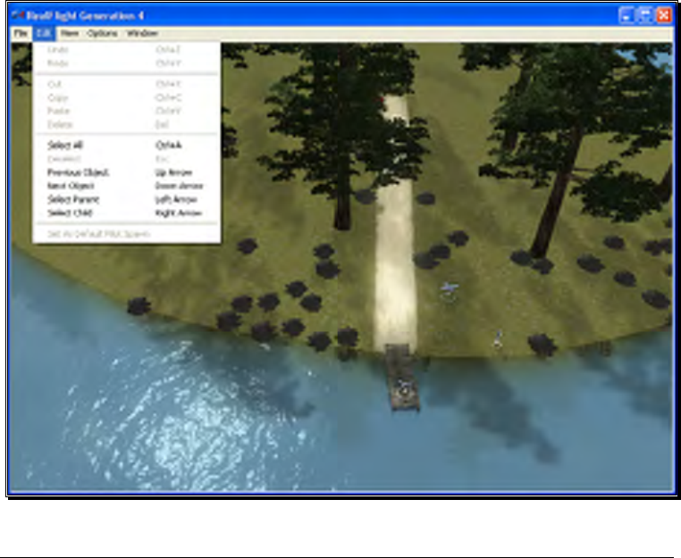
Edit Menu-
This menu may be used for some simple editing functions on the selected airport.

44
Undo-
Select this to undo the last change you made in the airport editor.
Redo-
Choose Redo to repeat the last action you did in the airport editor.
Cut-
Select one or more objects at the airport and choose Cut to remove the
selected objects. The objects are stored temporarily in RealFlight’s memory
and can be pasted back into an airport.
Copy-
Like the Cut options, Copy will store the selected objects in RealFlight’s
memory allowing you to later paste it into an airport. Unlike Cut, the selected
object will remain at the current airport.
Paste-
If any objects have been cut or copied, choose Paste to add them to the
current airport.
Delete-
Delete will remove the selected objects from the airport they cannot be
retrieved later. Therefore, you cannot paste the object(s) back in the scenery.
Select All-
This menu option will select all objects at the airport you are currently editing.
Deselect-
Choosing this menu option will deselect any airport objects that might be
selected at the moment. If no objects are selected, Deselect will remain grayed
out.
Previous Object-
If any airport object is currently selected, choosing Previous Object will select
the item on the folder list that is the preceding object.
Next Object-
If any airport object is current selected, choosing Next Object will select the
next object in the folder list.
45
Select Parent-
All objects belong to a group or parent. To pick the parent that the current
selected object belongs to, choose Select Parent.
Select Child-
If a group is currently selected, choose Select Child to select the first object
listed in that group.
Set As Default Pilot Spawn-
Choose a pilot spawn and click this menu option to set it to the default
spawning point. This point will be the default camera position each time you
load the current airport.
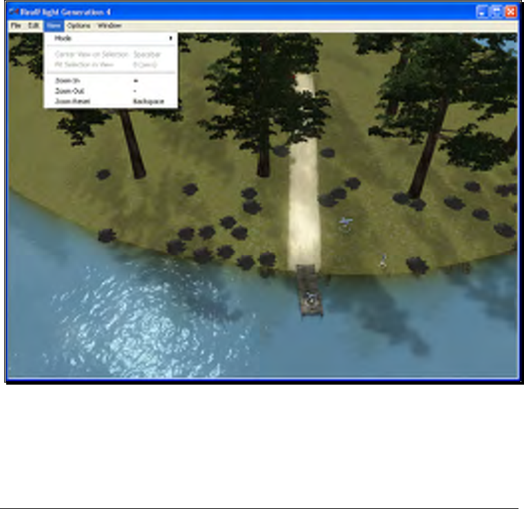
View menu-
This menu allows you to make alterations and modifications related to the perspective
of the simulation during the editing process. Modifications to the vantage point do not
have any effect on the simulation during its operation.
Mode-
The Mode menu is utilized to alter the camera perspective when viewing the
scene. There are three distinct view modes in G4: Pan Camera, Pivot Camera

46
and Normal Camera. These modes, as well as the methods to access them will
be discussed in depth in the sections that follow.
Pan Camera-
The Pan Camera option allows the camera to shift the vantage point
on the selected scenery.
There are several ways to access the Pan Camera mode. The first, and
probably the easiest, is to press the ‘C’ key on your keyboard.
Alternatively, you may right click on the scene and select Pan Camera
from the available options. The final method that may be used is to
select Pan Camera through the View menu and Mode menu item.
To increase the pan view, rotate the mouse wheel towards the
computer screen. Alternatively, you may also press the [-] (minus)
key on the number pad of the keyboard. This causes the camera to
pan out incrementally.
Conversely, to decrease the pan view, either rotate the mouse wheel
away from the computer screen or press the [+] (plus) key on the
keyboard’s number pad. This causes the camera to pan in
incrementally.
To move an object within the scene, left click on the object with the
mouse, continue to hold the button down, and move the mouse
within the scene. The selected object will move along with the mouse
cursor.
You can exit this mode by using the menus or by hitting the ‘Z’ key,
which returns you to the normal viewing mode.
Pivot Camera-
The Pivot Camera mode, as the name suggests, pivots or rotates the
camera in relationship to a particular object or location.
There are several ways to access the Pivot Camera mode. The first,
and probably the easiest, is to press the ‘X’ key on your keyboard.
Alternatively, you may right click on the scene and select Pivot Camera
from the available options. The final method that may be used is to
select Pivot Camera View menu and Mode menu item.
To increase the pivot view, rotate the mouse wheel towards the
computer screen. Alternatively, you may also press the [-] (minus)
key on the number pad of the keyboard. Doing so will cause the
camera to shift incrementally.

47
Conversely, to decrease the pivot view, either rotate the mouse wheel
away from the computer screen or press the [+] (plus) key on the
keyboard’s number pad. Again, this will shift the camera incrementally.
To exit the Pivot Camera feature, right click in the editing view once
again and then mouse click the desired option in the popup menu.
You can also exit this mode by hitting the ‘Z’ key, which returns you
to the normal viewing mode.
Normal Camera-
This mode returns the camera to its normal, or default perspective.
There are several ways to access the Normal Camera mode. The
easiest is to simply press the ‘Z’ key on the keyboard. Alternatively,
you may right click in the scene and select Normal Camera from the
options listed. Finally, you may select Normal Camera through the
View menu and Mode menu item.
Center View on Selection-
This option centers the vantage point on a particular object. This is useful for
repositioning, resizing, rotating, etc.
If you have not selected an object from the Folder Listing or highlighted an
object in the scene, this option will remain inactive or grayed out. If, however,
you have made a selection or highlighted an object, there are several ways to
select the Center View on Selection option.
Simply right click on the selected object or folder in the Folder Listing.
Alternatively, in the scene, right click on the highlighted object and select the
Center View on Selection from the options listed. The final option is to use
the View menu and select the Center View on Selection option.
To magnify the view or zoom in on the selected item, press the [+] (plus) key
on the keyboard. Each time you press the [+] (plus) key or select the Zoom
In menu item, the zoom level increases incrementally. Alternatively, you may
select the Zoom In option from the View menu.
To decrease the magnification, or zoom away from the selected item, press the
[-] (minus) key on the keyboard. Each time you press the [-] (minus) key or
select the Zoom Out menu item, the zoom level decreases incrementally.
Alternatively, you may select the Zoom Out option from the View menu.

48
Fit Selection in View-
This option is utilized to ensure that your selection fits in the view. If, for
example, your zoom magnification is at an extremely high level, the object may
not completely fit on the screen. This feature ensures that it will.
To access the Fit Selection In View, right click on the highlighted object in the
scene and select the Fit Selection In View from the options listed. The final
option is to use the View menu and select the Fit Selection In View option.
To magnify the view or zoom in on the selected item, press the [+] (plus) key
on the keyboard. Each time you press the [+] (plus) key or select the Zoom
In menu item, the zoom level increases incrementally. Alternatively, you may
select the Zoom In option from the View menu.
To decrease the magnification, or zoom away from the selected item, press the
[-] (minus) key on the keyboard. Each time you press the [-] (minus) key or
select the Zoom Out menu item, the zoom level decreases incrementally.
Alternatively, you may select the Zoom Out option from the View menu.
Zoom In-
Click this menu item to magnify or zoom in on the selected item. Alternatively,
you may magnify the view or zoom in on the selected item by pressing the [+]
(plus) key on the keyboard. Each time you press the [+] (plus) key or select
the Zoom In menu item, the zoom level increases incrementally.
Zoom Out-
Click this item to reduce the magnification, or zoom out of the current view.
Alternatively, press the [–] (minus) key on the keyboard. Alternatively, you
may zoom out via G4’s menus. Each time the [-] (minus) key or the Zoom
Out menu item are pressed or selected, the view will decrease incrementally.
Zoom Reset-
This menu item resets the view to the default magnification. Alternatively, you
may also press the Backspace on the keyboard to reset the zoom to its default
value.
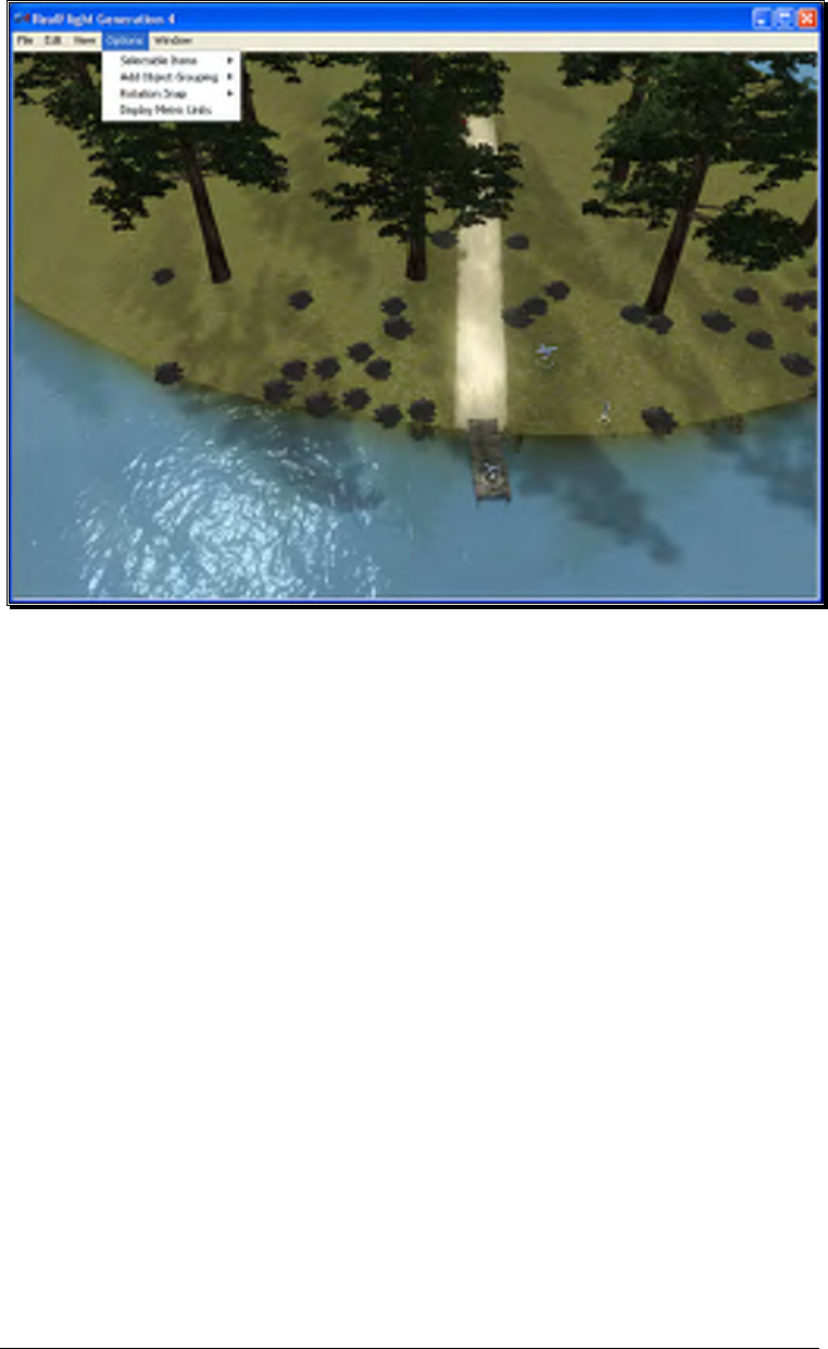
Options Menu-
The Options Menu allows you to adjust how many of the functions in the airport
editor will work.
49
Selectable Items-
The Selectable Items menu determines whether a particular type of object may
be clicked and selected on-screen.
To eliminate the possibility of selecting an item, simply mouse click on the
desired listing in the pull-down menu. This capability is useful if there are
many objects clustered in a small area and you want to select just one of them.
For example, suppose that an airport has a tight cluster of trees with a dirt pile
in the middle. If you want to select the dirt pile, it may be easier to turn off the
tree selection first. This will allow you to easily select the dirt pile without the
trees getting in the way.
Add Object Grouping-
The items available for addition in RealFlight G4 are all grouped or organized
accordingly. This menu item determines the methodology by which they are
grouped in the Object Palette window.
Product, Type, Name-
Selecting this option causes the objects in the Object Palette to be
displayed by the Product then by the Type and finally by the Name.
That is, objects are first listed within the product in which they appear
(e.g., G4, Expansion Packs, etc.). Within the product, the objects are

50
then classified by Type (e.g., Buildings, Trees, etc.). Once you’ve
selected the Product and Type of object that is desired, the objects are
then listed alphabetically by Name.
For information on adding objects and how to use the Object Palette,
please refer to the Object Palette section of this manual.
Type, Name-
This option causes the objects in the Object Palette to display by the
Type and the Name designations only. They are not sorted by the
Product in which they appear. Objects that appear in G4, Expansion
Packs, etc. will be included on one extensive listing.
This option is useful if you are unsure as to which product included a
particular object.
Name-
Selecting this option causes the objects to be listed in alphabetical
order by their name designations (e.g., Barn). This listing is extensive
as it includes all of the objects available to you.
This option is useful if you are unsure as to which product contained
the object or if you are unsure as to the type of object that you wish to
utilize. It also offers a rapid overview as to the number and breadth of
objects available to you.
Rotation Snap-
When rotating an object on the flying site, you have the ability to control the
amount of rotation with the Rotation Snap. There are four snap settings that
may be utilized in the editor to provide quick orientation settings for placing
objects.
None
The object rotates without any restrictions. This is useful for making
minor refinements to object placement.
45 Degrees
The object will rotate 45 degrees each time if this option is selected.
This is useful for making large changes to object position.
15 Degrees
The object will rotate 15 degrees each time if this option is selected.
51
5 Degrees
The object will rotate 5 degrees each time if this option is selected.
Display Metric Units-
Click this item with your mouse to switch the measurement indicators in the
Properties pane from SAE (feet, inches, pounds) to metric (meters,
centimeters, kilograms).
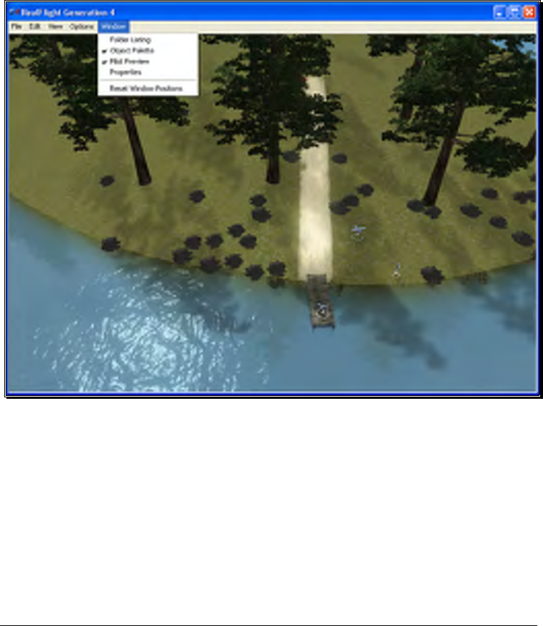
Window Menu-
This menu item activates or eliminates items from the display or window. For example,
if you were to click the Properties item in the pull-down menu this would eliminate the
Properties window from the screen.
Folder Listing-
This listing includes all of the folders available to you for use in the airport
editor. Selecting this item from the pull-down menu will remove the Folder
Listing dialog from the screen.

52
Object Palette-
The Object Palette includes the complete selection of objects available to you
for use in editing an airport. Selecting this item from the pull-down menu will
remove the Object Palette dialog from the screen.
Pilot Preview-
Selecting this item from the pull-down menu will eliminate the pilot’s
perspective from the screen.
Properties-
Selecting this item from the pull-down menu will remove the Properties dialog
from the screen.
Reset Window Position-
This menu item resets the positions of the airport editing windows back to
their default locations. Additionally, if you have removed any of the default
windows, they will return to the screen at this time.
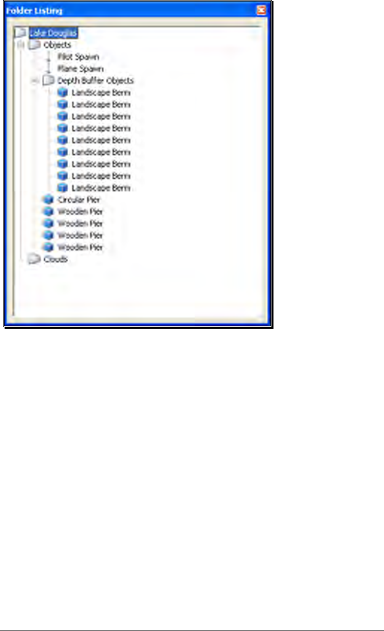
Utilizing the Editor
Opening the airport editor reveals four distinct windows. For the purpose of clarity,
we will examine each window individually. It is, however, important to note that these
windows interact with one another.
Folder Listing Window-
The Folder Listing window consists of the folders and items (objects) that comprise
the currently selected airport.
53
To determine what items are contained within the Objects and Clouds folders, click on
the [+] (plus) or double-click on the name itself (e.g., Objects). Doing so brings up
the various sub-folders that are contained within the main item.
As denoted by the [+] (plus) symbols, these folders, in turn, also have another level.
Again, to open these respective levels, click on the [+] (plus) icon or double-click the
folder name.
Alternatively, clicking on an object in the scene will highlight the respective object. It
will also open the folder that contains the object. The converse is also true, clicking the
folder or object in the Folder Listing menu will highlight the respective item as well.
If you wish to move an object from one folder to another, mouse click and hold the
object to be moved. Next, drag the object to the desired location (folder) using the
mouse and release. The object will be listed at the bottom of the folder in which it has
been situated. Please note: this removes the object from the original folder.
You may use either of two methods to delete an object from the folder, and therefore
the scene as well.
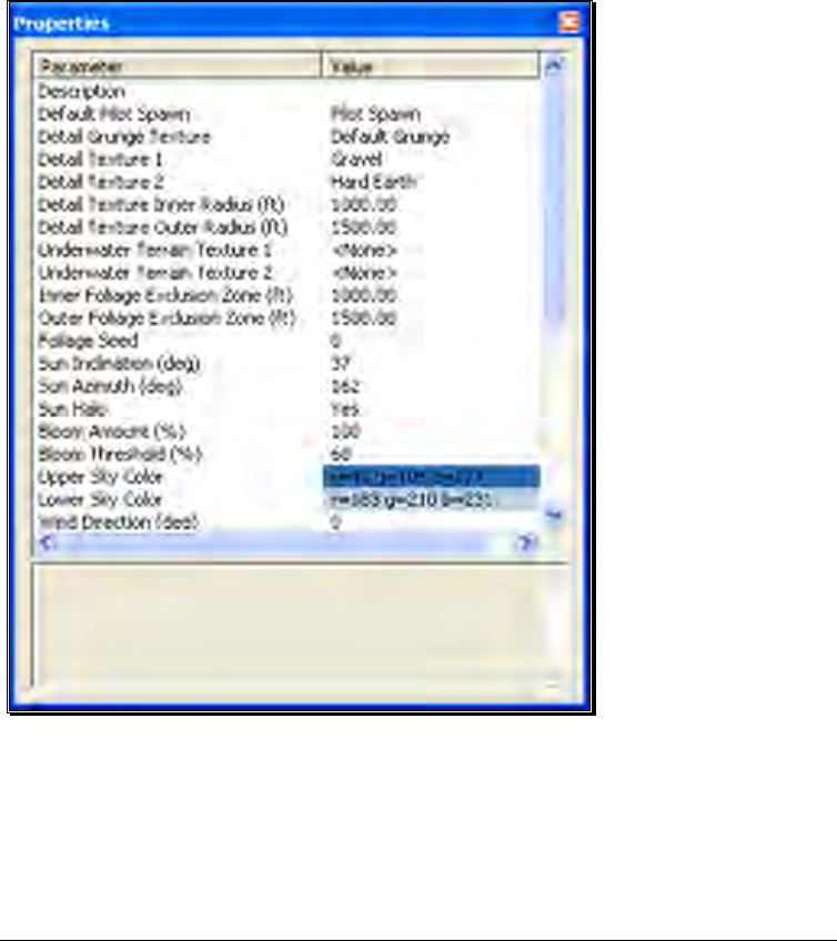
54
First, you can highlight the object or sub-folder (e.g., Fences) in the Folder Listing and
press the Delete key on the keyboard.
Alternatively, with the object or sub-folder highlighted, right click and select the Delete
Object pull-down option.
Properties Window-
The Properties window indicates the detailed information for the item highlighted in
the Airport Editor window. Consequently, the contents of the Properties window vary
depending upon the selection in the Folder Listing window.
The example below indicates what is displayed if the flying site’s root or top-level
folder is highlighted. Regardless of what is selected, the Properties are all very similar
in nature and in their method of modification.
An asterisk to the left of an item indicates that it has been modified. Right clicking the
item will bring up the Restore Original Value or Set to Default Value options.
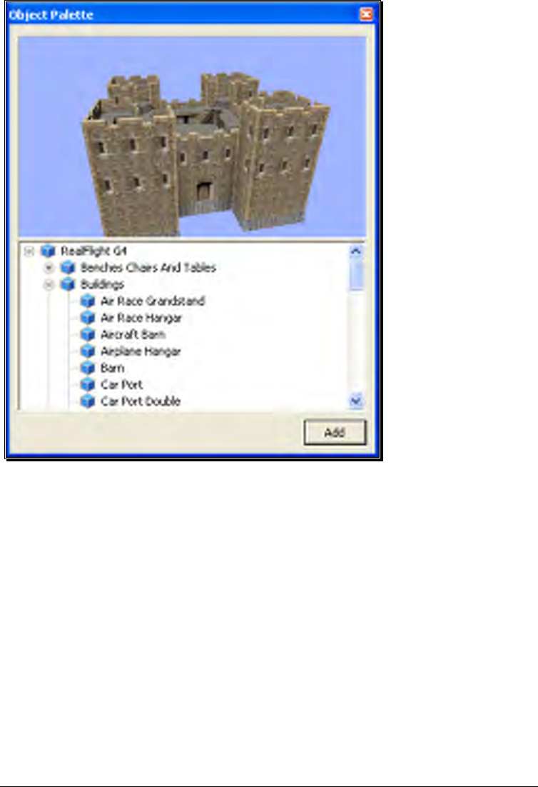
55
Object Palette Window-
The Object Palette window is used to add a new object or objects to the airport. The
object window consists of two separate sections: the preview box in the top section of
the window, and the objects list in the bottom section.
All objects are grouped according to their root directory. Within the root directory the
grouping is further refined. For example, you will find all available benches in the
Benches, Chairs and Tables group. This, of course, assumes that you are utilizing the
Product, Type, Name or Type, Name as determined by the Add Object Grouping
Selection in the Options menu.
Each object group is preceded with a [+] (plus) and an icon. The [+] (plus) indicates
that there is another expansion level, or selection, available to you. Clicking on the [+]
(plus) or double-clicking the respective root directory name (e.g., RealFlight G4) will
bring forward the pull-down menu of the items contained within the specified folder.
If, for example, you wanted to add a bench to the current airport, take the following
steps:

56
1. Click on the [+] (plus) icon in front of the Benches, Chairs and Tables group (or,
double-click the group name itself). This reveals the next expansion level to you.
2. From this expansion list, select the ‘Bench’ object. The selected object appears in
the preview box.
3. Click the Add button, which adds the object to the scene.
You will find additional information pertaining to object placement, positioning, etc., in
the Properties section of this chapter.
You may use any one of several available methods to change the location of an object
in the airport. To use the drag and drop method, click on the object to highlight it, as
shown below. Once you have highlighted the object, press and hold the mouse button.
Move the mouse to the desired location and then release the button to drop the object
in the new location.
Alternatively, with the object highlighted, right click the mouse elsewhere in the scenery.
This brings up a pop-up menu with several options available to you. To move the
selected object, point the mouse to the location that you desire and click the Move
Here option.
G4 also allows you to easily replicate the selected objects. To do so, hold the ‘Ctrl’ key
down, click and hold the mouse button and use the mouse to drag the object to a new
location. You will see that the original object stays in place. Release the mouse button
and the ‘Ctrl’ key to drop the new item in place.
Once you have added an object to the airport, you can modify it freely. Refer to the
Properties Window – Object Selection section for information on how to do so.
Pilot Preview-
This window provides you with the ability to view the scene from the pilot’s
perspective. It is very useful when editing PhotoField airports.

57
The number of pilot perspectives available to you varies; dependent upon the selected
scene. For example, RealFlight Ranch offers: Runway Center, Runway End and
Helipad as the viewing options. To select amongst these options, open the Spawn
Folder in the Folder Listing. Use the up/down arrow keys on the keyboard or the
mouse to select the desired perspective.
It is also possible to modify the selected vantage points. For example, you may Zoom
In and Out, or simply scan the horizon. Note that in order to modify the vantage
point, the Pilot Preview window must be the active window. To ensure that the Pilot
Preview window is the active window, simply click on, or in, this window.
To magnify the view or zoom in on the selected item, press the [+] (plus) key on the
keyboard. Each time you press the [+] (plus) key or select the Zoom In menu item,
the zoom level increases incrementally.
To decrease the magnification, or zoom away from the selected item, press the [-]
(minus) key on the keyboard. Each time you press the [-] (minus) key or select the
Zoom Out menu item, the zoom level decreases incrementally.
In most cases, you can also use the scroll wheel on the mouse to zoom in and out on
the scenery
RealFlight also allows you to scan the scene. To do so, press and hold the mouse
button. Moving the mouse will shift the scenery.
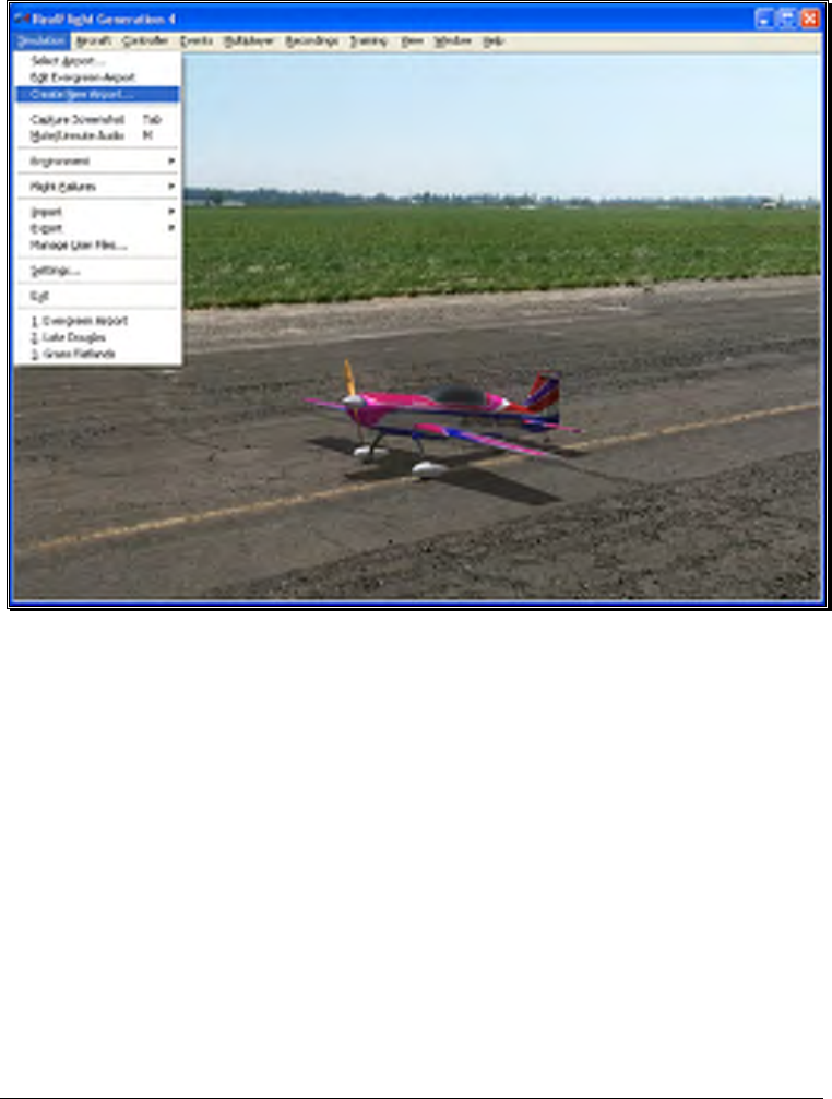
58
Create New Airport
This menu enables you to create an entirely new airport, starting with a fresh canvas.
The FlexiField flying site editor provides you with virtually unlimited editing options,
limited only by your imagination.
The options available to you when creating an airport are identical to those found in
the section pertaining to the airport editor above. As such, we will avoid duplicating
these instructions. Instead, we encourage you to experiment with the options, settings
and choices as you see fit.
After you have finished creating your airport, click the file menu and save the airport.
The airport name will appear in your RealFlight G4 directory for future use.
Capture Screenshot
Just like the perfect photo opportunity at the local flying field, RealFlight G4 offers the
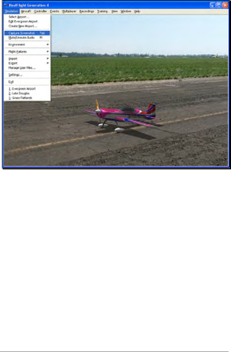
59
chance to snap off screenshots. Captured screenshots are great to share with friends,
add as your desktop wallpaper, or put on the internet for the world to see.
To snap a screenshot, click the Capture Screenshot menu item. Alternatively, press
the Tab key on the keyboard.
Screenshots are stored in the My Documents folder.
Mute/Unmute Audio
At times, you may want to fly without any sound. Choose this menu item to mute the
audio. Select it again to activate the sounds.
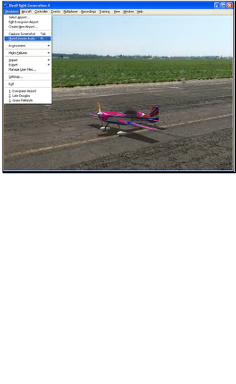
60
Environment
The Environment menu item has a number of sub menus that allows you to adjust the
sun location and wind settings.
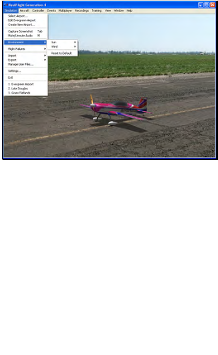
61
Sun-
RealFlight G4 gives you the ability to adjust the position of the sun in the sky.
By change the Azimuth, you can rotate the sun around you. Change the
Inclination to adjust how high in the sky the sun should be, or turn day into
night by moving the sun below the horizon.
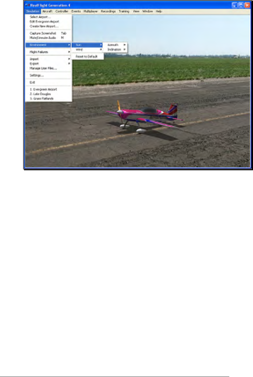
62
The sun settings are not applicable at PhotoField flying sites.
Adjusting the Sun Azimuth-
If you customize an airport, and find that the sun is always in your
flight path, adjusting the sun’s Azimuth is a good way to move it
around the sky, out of your way.
To adjust the Azimuth, select the Sun menu. This will bring forth the
Azimuth and Inclination options. Highlight the Azimuth menu item
in the pull-down selections. To rotate the sun to the right, click
Increase. Clicking Decrease will rotate the sun to the left.
Alternatively, you may increase or decrease the Azimuth by pressing
Shift + Home or Shift + End.
When altering the Azimuth, the simulation temporarily displays the
new location in the lower left corner of the window.
Adjusting the Sun Inclination-
To position the sun higher in the sky, or set it below the horizon,
modify the Inclination.
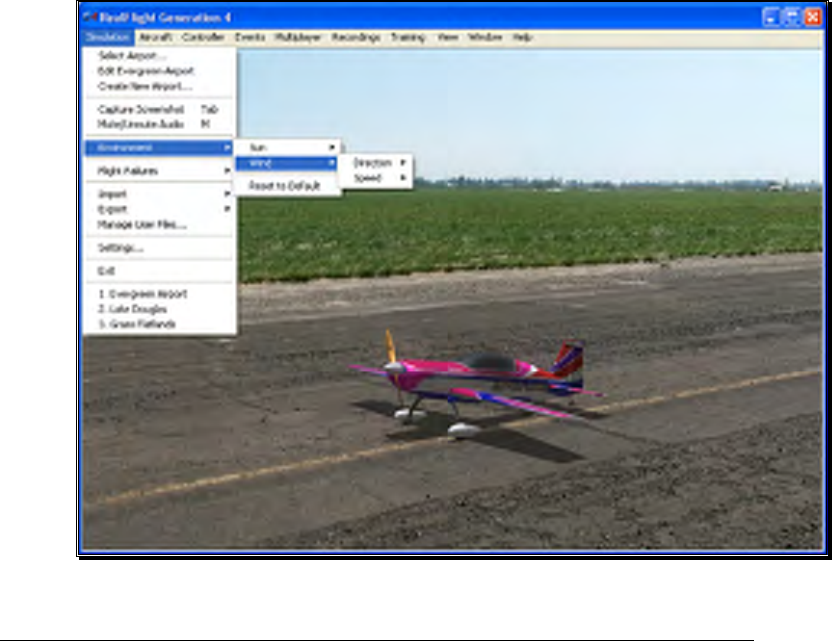
63
To adjust the Inclination, select the Sun menu. This will bring forth
the Azimuth and Inclination options. Highlight the Inclination menu
item in the pull-down selections. To raise the sun higher into the sky,
click Increase. Click Decrease lower the sun, or to set it below the
horizon to make it night time.
Alternatively, you may increase or decrease the Inclination by pressing
Shift + Page Up or Shift + Page Down.
When altering the Inclination, the simulation temporarily displays the
new location in the lower left corner of the window.
At night time, RealFlight G4 will automatic turn on the lighting effects
on objects and aircraft that offer the lighting abilities.
Wind-
RealFlight G4’s TruFlo Wind Dynamics offers the most realistic wind model
of any R/C simulator. Its five components work together to capture this
complex, ever-changing force with unmatched realism. Just as it would at the
field, your model will encounter a variety of wind forces as it soars across the
skies in RealFlight. Sailplane enthusiasts will appreciate the lifelike effect of the
winds as they follow the drafts on the slopes and hills of G4.

64
RealFlight offers you the ability to adjust both the speed and direction of the
wind. To access the Wind settings, click on the Simulation menu followed by
the Wind menu item. Several methods may be utilized to adjust the wind
speed and direction.
Adjusting the Wind Direction-
RealFlight G4 also allows you to alter the direction (expressed in
degrees) of the wind as well. This function is perfect for practicing
crosswind landings.
Selecting the Wind menu item brings up the Speed and Direction
options. To adjust the wind direction, highlight the Direction menu
item in the drop-down selections. To increase the degree of wind
direction, click on the Increase option in the drop-down selections.
Likewise, clicking the Decrease option lowers the degree of wind
direction. The wind direction degree increases and decreases in 15-
degree increments.
You may also adjust the Direction through the Settings… menu item.
This method allows you to adjust the direction in one-degree
increments.
Alternatively, you may increase the angle of the wind direction by
pressing the Home key on the keyboard. To decrease the angle of the
wind direction, press the End key on the keyboard.
When altering the wind direction, the simulation temporarily displays
the new wind direction in the lower left corner of the window.
Adjusting the Wind Speed-
Increasing the wind speed is an ideal way to learn to fly in the less-
than-perfect wind conditions that frequently occur at an R/C field. To
adjust the speed of the wind, select the Wind menu. This will bring
forth the Speed and Directions options. To adjust the speed of the
wind, highlight the Speed menu item in the pull-down selections. To
increase the speed of the wind, click on the Increase option in the
pull-down selections. Clicking the Decrease option reduces the wind
speed.
Alternatively, you may increase the wind speed by pressing the Page
Up key on your keyboard. To decrease the speed of the wind, press
the Page Down key on your keyboard. Each time the Page Up or
Page Down is pressed the wind is increased or decreased incrementally.
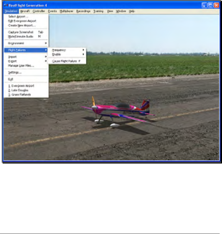
65
When altering the wind speed, the simulation temporarily displays the
new wind speed in the lower left corner of the window.
Alternatively, you may adjust the Wind through the Settings… menu item.
For information on how to do so, please refer to the Settings section on page
75.
Flight Failures
RealFlight G4 offers the ability to simulate common failures for your aircraft. This
feature aids in teaching you how to remain calm and react appropriately when an actual
failure occurs at your R/C field. RealFlight G4 allows you to determine both the types
of flight failures that you will face as well as how often those failures will occur.
Adjust the Rate of Occurrence-
There are several methods available to adjust the frequency at which flight
failures will occur. To use the first method, click on the Simulation menu
followed by the Flight Failures menu item, and then the Frequency menu
item. This brings up a sub-menu as shown in the screen below. Once the sub-
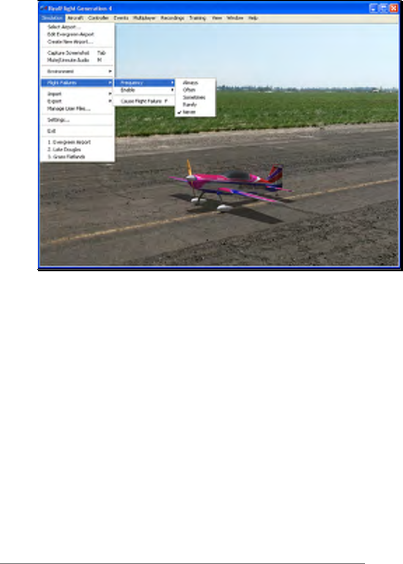
66
menu is visible, simply mouse click on one of the options in the pull-down
menu.
Alternatively, you can adjust the rate of occurrence in the Settings… menu
item. To access this menu item, click on the Simulation menu followed by
the Settings… menu item. Next, click on the Flight Failures listing. You
can bring forth the Flight Failures options by clicking on the [+] (plus) or by
double-clicking on the Flight Failures listing itself. To adjust the frequency of
occurrence, click on the value as indicated in the column to the right of the
probability indicator.
The Settings section on page 75 discusses the Flight Failures options in detail.
If you do not wish to experience any flight failures, click the Never option in
the drop-down menu. Conversely, if you wish to gain a great deal of
experience at handling emergencies, click the Always option. The Always
options means that each time you reset the aircraft, something is guaranteed to
go wrong. Maybe not right away – an engine failure will usually wait until
some entirely inconvenient time to reveal itself, but it will happen. The Rarely
option corresponds to roughly a 5% chance per reset that something will fail.
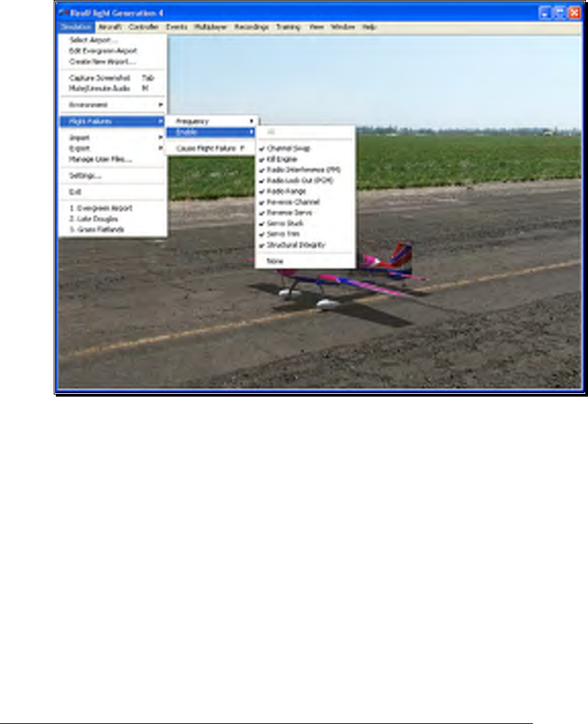
67
Selecting the Type of Flight Failures-
As noted previously, RealFlight G4 also allows you to determine the type of
flight failures that you will experience within the simulation. To do so, click
the Simulation menu followed by the Flight Failures menu item. Next,
select Enable to bring forth the list of available flight failures. If an item has a
check mark next to it, then that flight failure is enabled. To disable the flight
failure, click on it with the mouse.
Cause Flight Failure-
This feature causes a flight failure to occur. To access this menu item, click on
the Simulation menu, and then click on the Cause Flight Failures menu
item. As an alternative, press the ‘F’ key on your keyboard to cause a flight
failure.
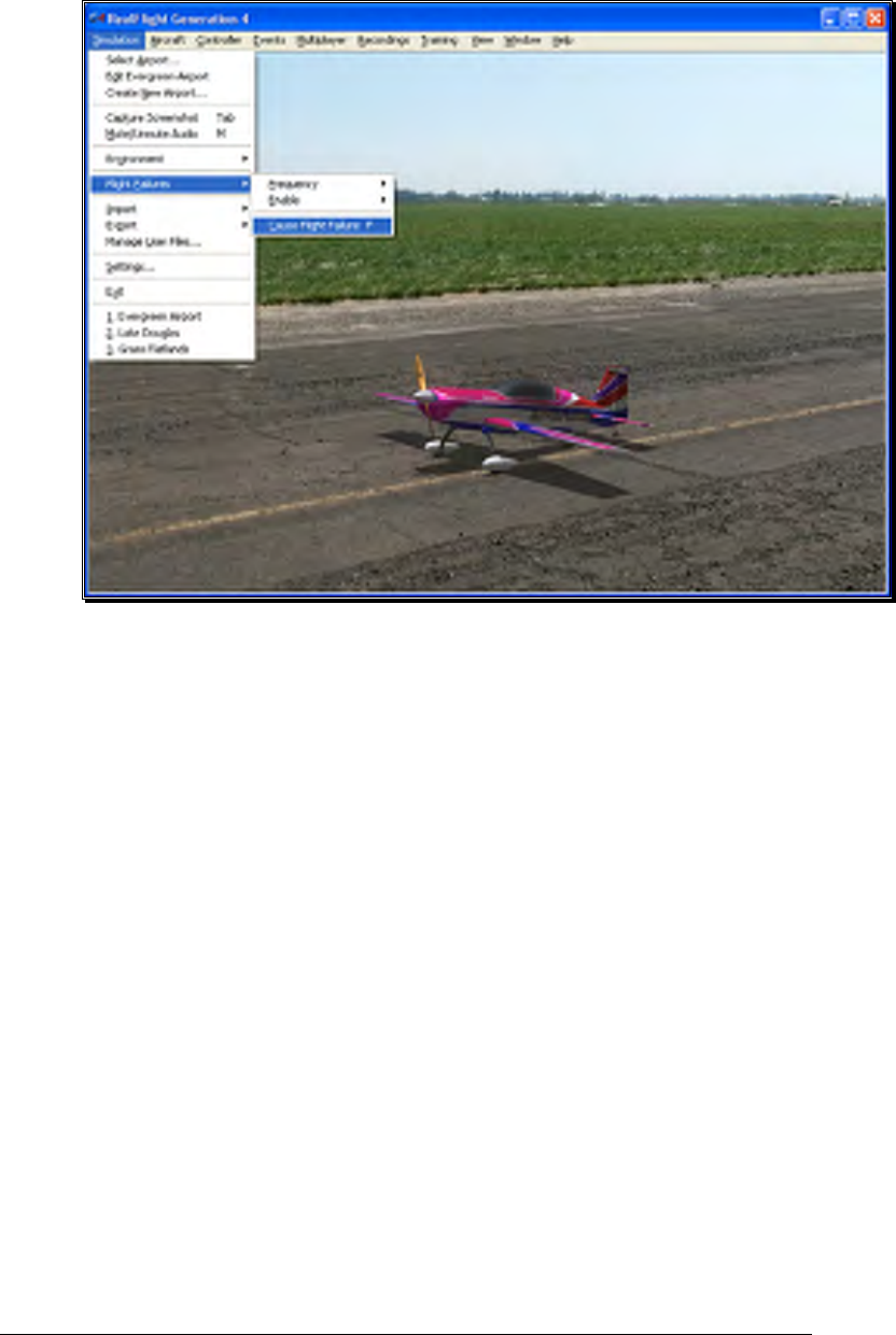
68
Import
The Import menu item allows you to utilize, or import, content created by other users.
There are three types of files that are associated with RealFlight G4; each will be
covered in the section that follows.
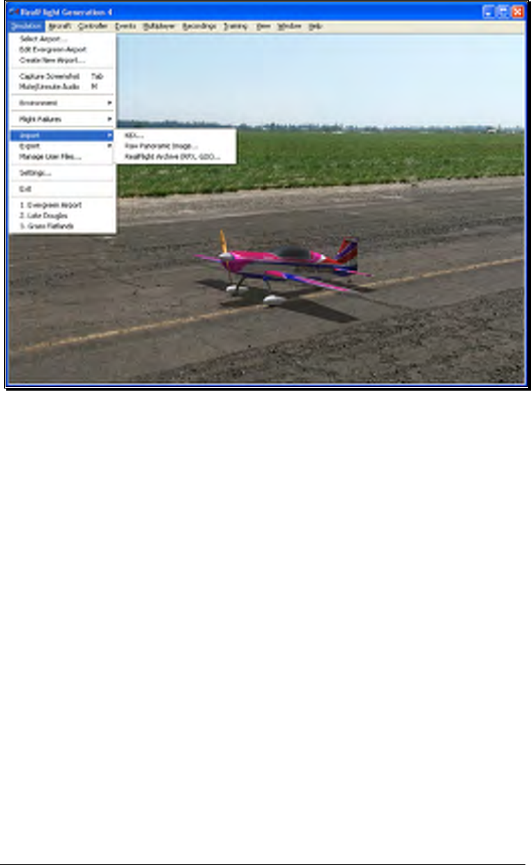
69
KEX-
Knife Edge Software has created a plug-in, or software module that functions
with popular 3D modeling tools to create subject matter for the RealFlight
software.
The KEX importer is used to bring the model from the plug-in into the
simulation itself.
For more information, see: http://www.knifeedge.com/KEmax/
Raw Panoramic Image-
This file type refers to the panoramic image that helps generate the PhotoField
flying sites. This option allows you to create a PhotoField using a panoramic
image that you may have downloaded or created yourself. It works best with
large images (8000x4000) that are equirectangular, spanning 360 degrees
horizontal by 180 degrees vertical. Click on the Raw Panoramic Image…
selection to import an image into the simulation. Browse to the location of the
image you would like to import. The image may be either a bitmap (.bmp),
targa (.tga) or a JPEG (.jpg) file extension.
Once you have located the appropriate folder and desired image, double-click
the image. Alternatively, select this image and click Open. The conversion

70
process can take several minutes for large images. When the process is
complete, G4 will automatically create a new PhotoField airport that uses your
newly imported image.
To edit the new PhotoField airport (for image alignment, object placement,
etc.), access the Airport Editor. To do so, click the Simulation menu,
followed by the Create New Airport… menu item. To see the image from
the pilot’s perspective, refer to the Pilot Preview window. This will make it
easier to place objects and adjust the image correctly. If necessary, adjust the
image using the Panoramic Image Y Alignment, Panoramic Image X
Alignment and/or the Panoramic Image Facing options located in the
Properties window.
RealFlight Archive (RFX, G3X)-
RFX is the file extension that is used for all files exported from RealFlight G4.
This menu option allows you to import an RFX file. You will use this for all
files that you have downloaded. There is nothing special you need to know
about the file beforehand; the RFX importer handles all types of content,
including planes, color schemes, airports, PhotoFields, and recordings.
After choosing the Import menu item followed by the RealFlight Archive
(RFX, G3X), you will be presented with an Open file dialog. Use this dialog to
find the file that you want to import. Double-click the file or click the file and
click Open. The import process will start immediately and once it’s finished
you will see a message confirming its success.
This menu item also allows you to import G3X files used in RealFlight G3 and
G3.5.
Export
The Export menu item allows you to share user-created content. It is provided in the
menu as a shortcut to using the Manage User Files dialog.
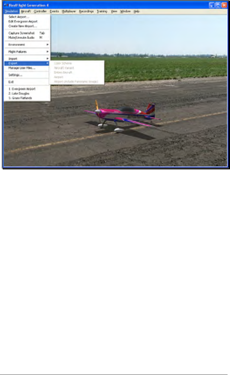
71
G4 users may share the following items: Color Schemes, Aircraft Variant, Entire
Aircraft, Airport and Panoramic Images. If one or more of these options on the list is
grayed out, it is because the currently loaded color scheme, aircraft, or airport is part of
the simulation by default and not available for export.
Once any of these items are exported, you can then share them with friends or the rest
of the RealFlight community. The best choice is to upload the files to the RealFlight
swap site found at:
http://www.knifeedge.com/forums/downloads.php?
Color Scheme-
This option allows you to share the current aircraft color scheme (a.k.a. trim
scheme) with other RealFlight users.
To export a Color Scheme, select the Export menu item followed by the
Color Scheme option. A save dialog will appear so that you can choose
where you would like to save the exported color scheme and determine the
filename. After saving, a message will appear on-screen advising you whether
or not the export was successful. This message will also list the location and
name of the file that was exported.

72
Aircraft Variant-
This option enables you to export an aircraft that has undergone structural
modifications such as lengthened wing span, more prop thrust, different
airfoils, etc. It is important to note in addition to any wire frame modifications,
the Aircraft Variant file option also includes any modifications to the aircraft
powerplant, batteries, etc.
To export an aircraft variant, select the Export menu item followed by the
Aircraft Variant option. A save dialog will appear so that you can choose
where you would like to save the exported color scheme and determine the
filename. A verification message will appear on-screen advising you whether
or not the export was successful. This verification message will also list the
location and name of the file that was exported.
Entire Aircraft-
This option enables you to export the entire contents of an aircraft such as
trim scheme, structural changes, etc.
To do so, select the Export menu item followed by the Entire Aircraft option.
A save dialog will appear so that you can choose where you would like to save
the exported color scheme and determine the filename. A verification message
will appear on-screen advising you whether or not the export was successful.
This verification dialog will also list the location and name of the file that was
exported.
Airport-
This option enables you to export a modified airport. Note that any custom
panoramic image you may be using with this airport will not be exported. To
export an airport with a custom panoramic image, use the “Airport (include
Panoramic Image)” option.
To export an airport, select the Export menu item followed by the Airport
option. A save dialog will appear so that you can choose where you would like
to save the exported color scheme and determine the filename. After saving, a
verification message will appear on-screen advising you whether or not the
export was successful. This verification message will also list the location and
name of the file that was exported.
Airport (include Panoramic Image)-
This option enables you to export an airport along with its custom panoramic
image. To do so, select the Export menu item followed by the Airport
(include Panoramic Image) option. A save dialog will appear so that you
can choose where you want to export the airport and what you want to name
the file. A verification message will appear on-screen advising you whether or
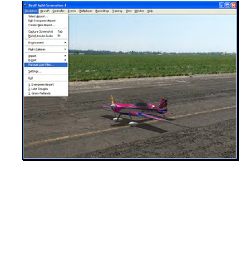
73
not the export was successful. This verification message will also list the
location and name of the file that was exported. You may then upload the
exported file to a web site for others to enjoy.
Manage User Files
The Manage User Files menu item allows you to modify the new user content that you
have added to the simulation. You will find that the Manage User Files menu item is a
handy tool as it maintains all such files in one, easy to find location.
The Manage User Files dialog allows you to copy, rename, delete, or export
any custom resource that exists in the simulation. It is important to note that
the various Manage User Files buttons will be inactive until a modification to
one of the files exists. That is, this menu item is only utilized to modify user-
created items. It will not allow you to modify the airports or vehicles included
in the RealFlight Generation 4 software.

74
Copy-
This option duplicates the information and data pertaining to the currently
selected item. If, for example, you wish to duplicate a flying site located in the
User Files, click the Copy button.
Once you have copied the respective file, enter a name for the new item.
Using our previous example, simply rename the flying site as desired. This
new name will then be used in the Select Airport dialog.
Rename-
This option is utilized to rename a user-created item.
To do so, highlight the desired item (flying site, etc.) and click Rename. Enter
the desired name for the respective item in the dialog provided. The item will
now appear in its respective list of offerings with the new name.
Delete-
This option is utilized to delete an item entirely. All files associated with the
item will be removed from your computer.
Again, it is important to note that users are only allowed to delete items which
they, or other users, have created. That is, you are not allowed to delete default
items that are included with the software.
To delete a user-created item, select the respective item in the User File menus
and click Delete. If you wish to delete this item, click Yes in the verification
dialog. Please note: once deleted this resource will no longer be available in the
simulation.
Export-
This button is used to Export, or place the airport/aircraft/recording in a
location so that the user may share it with others. If you have created
interesting or unusual content, we encourage you to share your designs with
other RealFlight users. The more content that is shared the more enjoyment
everyone will experience.
To export a user-created item, select the respective item in the User File menus
and click Export. A verification dialog will appear on-screen advising you
whether or not the export was successful and the location and name of the file
that was exported. You may upload the exported file to a web site, move it to
another computer, or email it for others to enjoy.
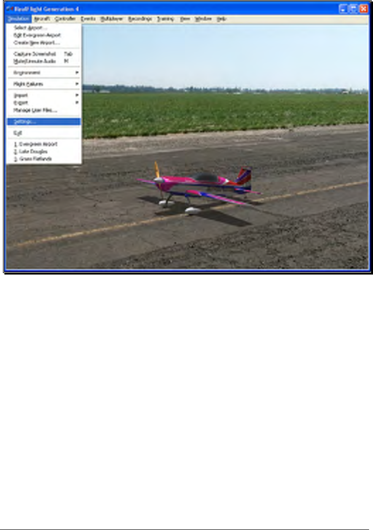
75
Settings
The Settings options are an integral part of the G4 software. This menu item allows
you to adjust a multitude of features and functions within the simulation.
To access this menu item, click on the Simulation menu followed by the Settings…
menu item. The Settings dialog will appear, showing the available options.
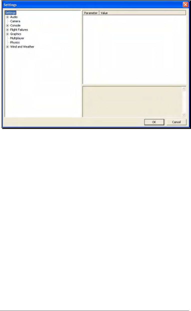
76
The Settings that are available to you are as follows:
• Audio
• Camera
• Console
• Flight Failures
• Graphics
• Multiplayer
• Physics
• Wind and Weather
Audio-
Audio settings are split into two different categories which are as follows. Double-click
on the Audio name, or click on the [+] (plus) to expand the list and show the Audio
options.
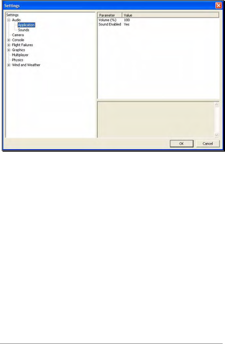
77
Application-
The Application section controls the sound over the entire simulator.
• Volume (%) - This setting adjusts the master volume level for the entire
simulator.
• Sound Enabled - Choosing No for this option will mute all sounds for the
simulator.
Sounds-
The Sound settings control the various options related to the miscellaneous
sounds within the simulation. RealFlight allows you to make modifications to
the various sounds based upon your preferences.
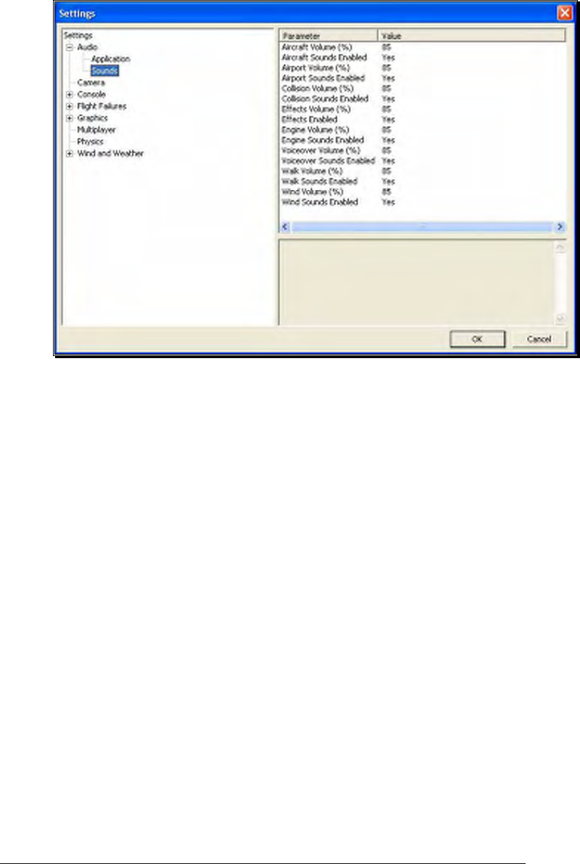
78
For each type of sound that is adjustable, there are two parameters that can be
changed. First is the Volume, which is a percentage of the overall volume.
The second is whether the sound should be enabled or muted.
The different sound types are:
• Aircraft – effects aircraft related sounds such as servos.
• Airport – effects the ambient sounds around the airport.
• Collision – adjust these to effect the crashing sounds associated with
collisions.
• Effects – this represents the miscellaneous sounds that don’t fit into
any other category.
• Engine – adjust this to effect the motor and engine sounds.
• Voiceover – these parameters adjust the voiceovers used for the
Virtual Flight Instructions.
• Walk – adjusts this to control the walking sound when moving the
camera angle.
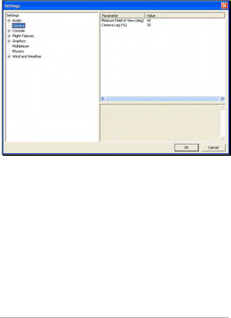
79
• Wind – this effects the sound produced by the wind.
Camera-
The camera options available to you are designed to enhance the field of view when
utilizing the Keep Ground in View zoom mode. For additional information on this
option, please refer to the View menu section of this manual.
Minimum Field of View (deg)-
This setting determines the absolute minimum field of view when utilizing the
Keep Ground in View zoom option.
To adjust the minimum field of view, click the existing value. Next, enter the
desired value either directly from the keyboard or via the mouse wheel.
Camera Lag (%)-
This controls how quickly the camera reacts to the aircraft’s movements. If
the lag is set to zero, the camera always looks directly at the aircraft. At all
other values, the camera will have a spring-like reaction to the aircraft during
flight.
At very high values, the camera hardly ever looks directly at the aircraft, and
often the aircraft will fly off the screen as the camera tries to catch up. At
lower values, the effect is very subtle and yet still softens the camera movement
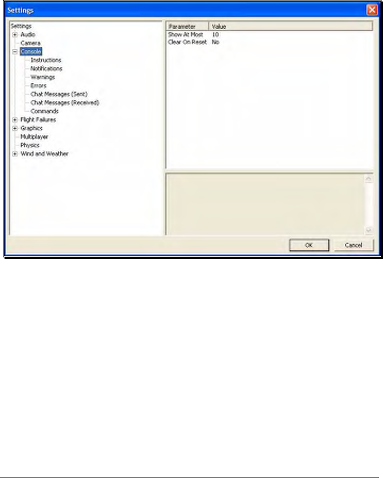
80
enough so that minor changes in the aircraft’s speed/position are more
noticeable.
Please note: these settings apply to fixed view cameras only. They are not
applicable to the cockpit or chase views.
Console-
The Console option has a number of sub-categories that allow you to perform
modifications to the messages that appear on-screen while running the simulator. It
also offers two parameters that effect all the sub-categories.
Show At Most-
This numerical value indicates the maximum number of messages that will
appear on your screen at any given time. When the maximum number is
surpassed, an older message will be removed and the most recent message will
take its place on-screen.
To adjust the number of messages displayed on-screen at one time, click on
the value as indicated in the column to the right of the Show At Most indicator.
Input the desired value directly from the keyboard or use the mouse wheel.

81
Clear on Reset-
This setting controls whether all the on-screen messages are cleared when the
aircraft resets. This prevents the screen from becoming overly cluttered with
messages and information.
Using either the up/down arrow keys on the keyboard, or the mouse, select
either Yes (messages automatically clear) or No (messages remain on-screen
after a reset) from the pull-down listings. If using the up/down arrow keys,
press Enter to finalize your selection.
Double-clicking on the Console name or clicking on the [+] (plus) will bring forth
the following options:
• Instructions
• Notifications
• Warnings
• Errors
• Chat Messages (Sent)
• Chat messages (Received)
• Commands
Each of the System Messages screens is independently adjustable and may be tailored
to suit your personal preferences. For information on how to do so, please read the
following section.
Instructions-
As the name suggests, modifications will affect only the System Instructions.
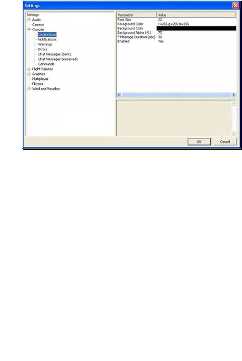
82
Font Size-
This option allows you to adjust the font size for the messages
pertaining to the instructions. Please note: this only effects the
Instructions. It does not effect any other system messages.
To access the Font Size options, click on the value shown in the
respective column. The desired values may be input directly from the
keyboard or modified using the mouse wheel.
Foreground Color-
This option allows the user to adjust the color of the foreground for
the Instructions messages.
To access the options pertaining to the foreground color, click on the
current value. Click the more options button (the gray folder with
the ellipsis) to bring forth the palette of available colors. This will
reveal a screen that appears as follows:

83
To select a color, click the desired color on the palette. If you wish to
make a custom color, click the Define Custom Colors button and
create the color or colors to suit your tastes. Click OK to finalize the
selection. The selected color will be reflected immediately in the value
column.
Background Color-
As with the Foreground Color, this setting allows the user to adjust the
color of the background for the Instructions messages.
To access the options pertaining to the background color, click on the
current displayed color.
Click the more options button (the gray folder with the ellipsis) to
bring forth the palette of available colors. To select a color, click the
desired color on the palette. If you wish to make a custom color,
click the Define Custom Colors button and create the color or colors
to suit your tastes. Click OK to finalize the selection. The selected
color will be reflected immediately in the value column.
Background Alpha (%)-
This option adjusts the transparency of the text background for the
message.

84
The desired values may be input directly from the keyboard or
modified using the mouse wheel. The higher the value, the more
transparent the text background will become.
Message Duration (sec)-
This option adjusts the length of time that a message remains on-
screen before it disappears.
You may input desired values directly from the keyboard or modify
them using the mouse wheel. Of course, the higher the value, the
longer the message remains on-screen.
Enabled-
This option determines whether Instructions messages are displayed or
not.
To determine whether this is enabled, click on the respective value
indicator. Using either the up/down arrow keys on the keyboard, or
the mouse, select either Yes (Instructions messages are enabled) or
No (Instructions messages are disabled) from the pull-down listings. If
using the up/down arrow keys, press Enter to finalize your selection.
Notifications-
To select the Notifications options, click on the Notifications name. These
options function in the same manner as the options for the Instructions
messages, except that they only affect Notification messages.
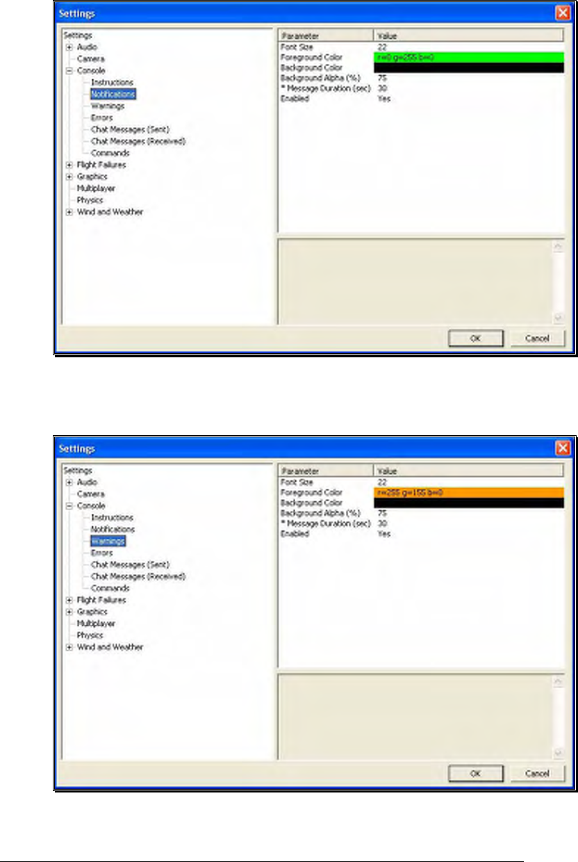
85
Warnings-
This option determines the settings for the system warning messages.
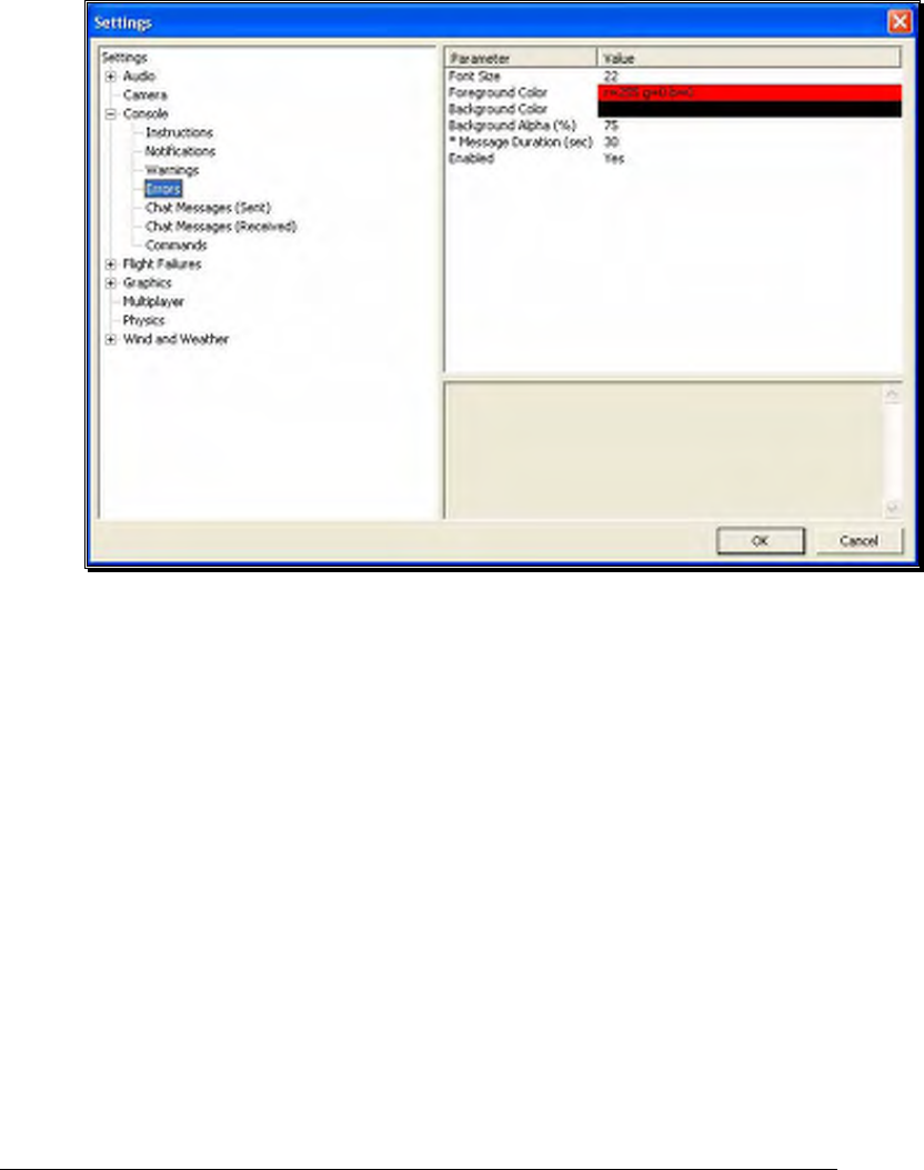
86
To select the Warnings options, click on the Warnings name. These options
function in the same manner as the options for the Instructions messages,
except that they only affect Warning messages.
Errors-
This option allows you to modify the behavior of system error messages.
To select the Errors options, click on the Errors name. These options
function in the same manner as the options for the Instructions messages,
except that they only affect Error messages.
Chat Messages (Sent)-
This option allows you to modify the appearance of text that you type for chat
messages during multiplayer sessions.
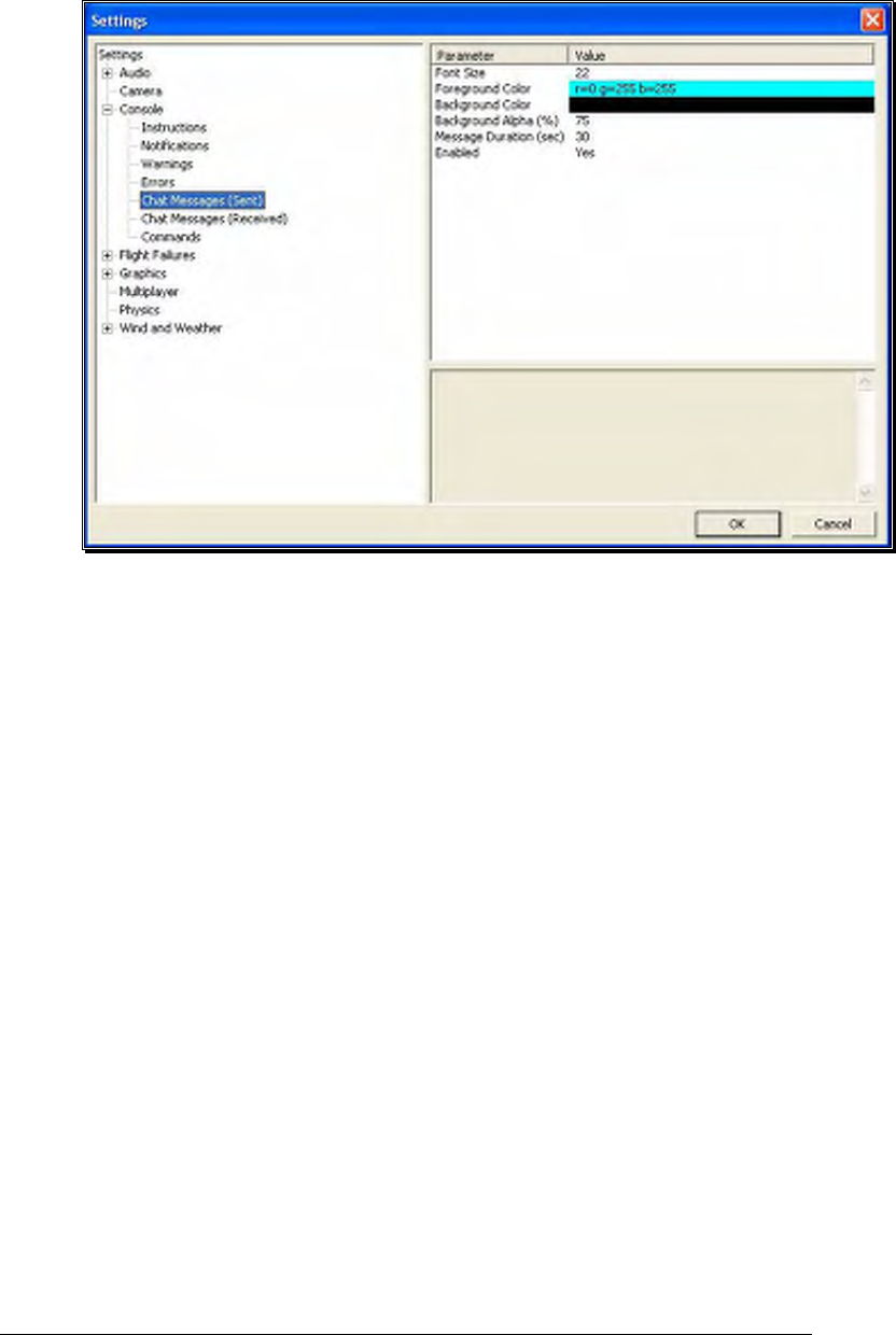
87
To select the Chat Messages (Sent) options, click on the Chat Messages (Sent)
name. These options function in the same manner as the options for the
Instructions messages, except that they only affect Chat Messages (Sent)
messages.
Chat Messages (Received)-
This option allows you to modify the appearance of text that you receive from
other players during multiplayer sessions.
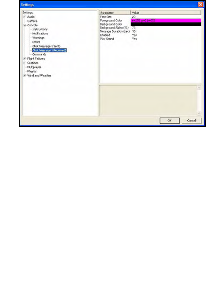
88
To select the Chat Messages (Received) options, click on the Chat Messages
(Received) name. These options function in the same way as the options for
the Instructions messages, except that they only affect Chat Messages
(Received) messages.
There is one additional parameter available for this option called Play Sound.
This allows you to set whether a sound is heard when an incoming chat
messages arrives.
Commands-
This option allows you to modify the appearance of commands typed in the
console screen.
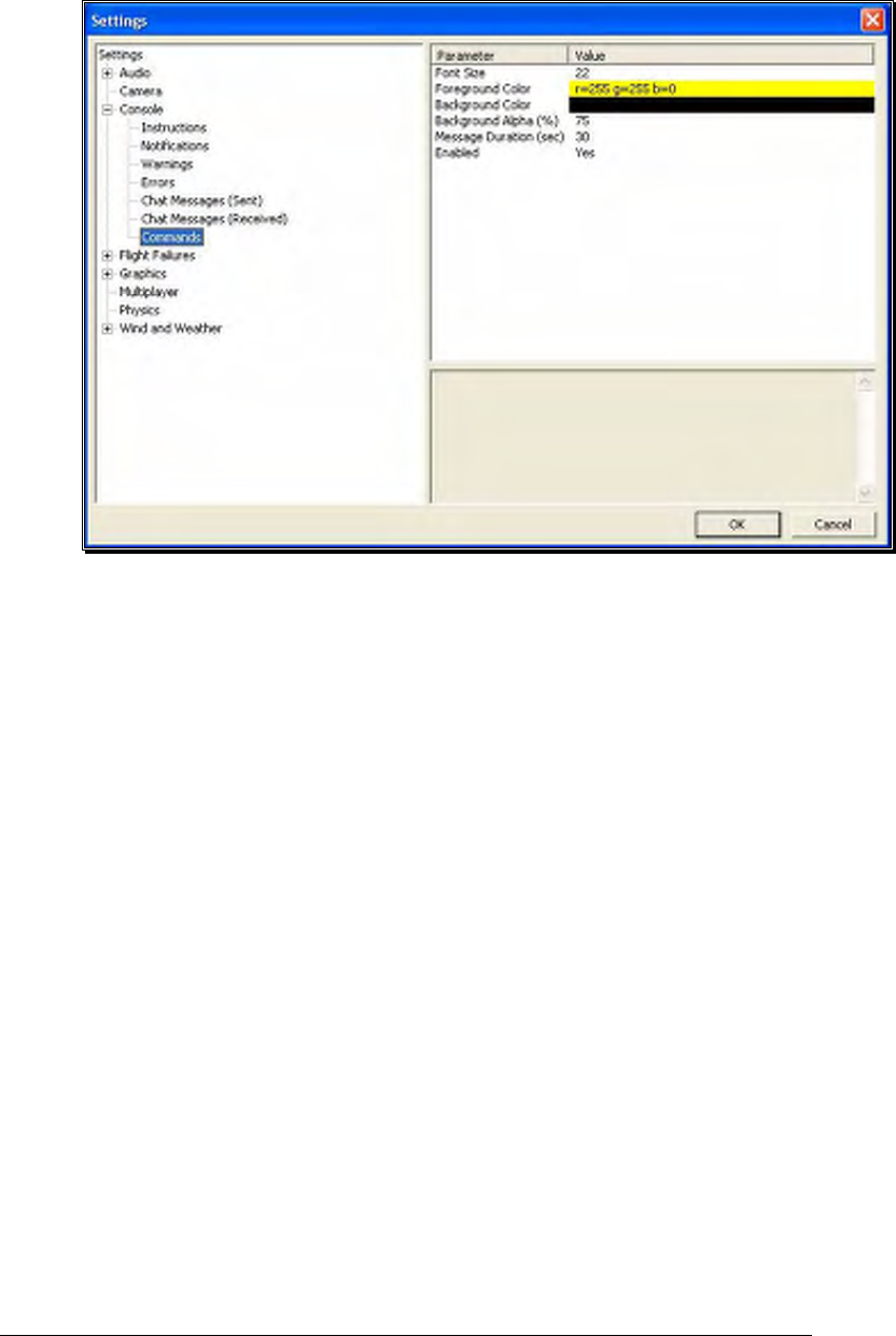
89
To select the Commands options, click on the Commands name. These
options function in the same manner as the options for the Instructions
messages, except that they only affect Commands messages.
Flight Failures-
To adjust the Probability options or the Notify When settings, click on the Flight
Failures root directory.

90
Double-click on the Flight Failures name or click on the [+] (plus) to expand the list
and show the Flight Failures options. RealFlight defaults all Flight Failures to enabled
(active). Each item may be enabled or disabled individually. To disable a specific flight
failure, click on the respective failure located within the pull-down list. Next, click on
the Yes value as indicated in the value column. This brings forth the Yes/No pull-
down list. To disable the respective failure, simply choose the No option. For
example, to disable the Reverse Servo flight failure:
1. Select the Reverse Servo option in the Flight Failures sub-menu
2. Click the Yes in the right hand pane
3. Select No from the pull-down list
Probability-
To adjust the frequency of occurrence, click on the value as indicated in the
column to the right of the probability indicator.
If you do not wish to experience any flight failures, select the Never option in
the drop-down menu. Conversely, if you wish to gain a great deal of
experience at handling emergencies, click the Always option.
Notify When-
This setting allows you to determine if, or when, RealFlight notifies you as to
the flight failure experienced.

91
To adjust the settings of this feature, click on the value as indicated in the
column to the right of the Notify When indicator. Your options are:
After Flight - RealFlight will advise you as to the flight failure experienced
upon the completion of the flight.
Before Flight - RealFlight will tell you which flight failure you are about to
experience before the flight begins.
Never - RealFlight G4 will never advise you as to the flight failure that you
have experienced, or are about to experience. A little mystery is a good thing.
On Failure - RealFlight will tell you about the flight failure just as it occurs.
The different Flight Failures available in RealFlight G4 are as follows:
• Reverse Servo - The travel direction of one of your servos is reversed.
• Kill Engine - The engine will fail or quit in flight, which means that you will have
to perform a deadstick landing or autorotation.
• Servo Stuck - A servo will become fixed, or stuck, in a certain position.
• Servo Trim - A servo alters the trim settings, modifying the flight control position.
• Channel Swap - This failure simulates the effect of inadvertently swapping two
channels. As an example, you may find that your rudder controls the throttle, and
vice versa.
• Radio Lockout (PCM) - The receiver will experience intermittent radio dropouts
during which time the aircraft will fail to respond to control inputs.
• Radio Interference (FM) - The receiver will experience intermittent radio
interference during which time the servos will behave erratically.
• Radio Range - The receiver will experience interference proportional to the
distance between the pilot and the aircraft. If the aircraft is close to the pilot’s
position, the range problems will be minimal, increasing as the aircraft gets farther
away.
• Reverse Channel - One of the channels, selected at random, will operate in reverse
direction.
• Structural Integrity – This failure determines how strong the aircraft is and if parts
could break off during flight. This failure also has a parameter called Allow
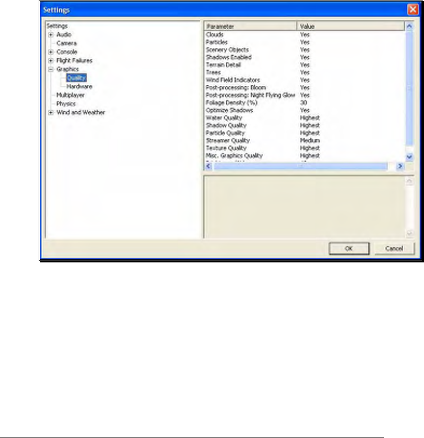
92
Multiple Failures which allows this flight failure to be triggered more than once
during a flight.
Graphics-
Double-click on the Graphics name or click on the [+] (plus) to expand the menu
and display the various Graphics options available to you.
Quality Options-
The Quality options are quite useful in fine-tuning your simulator to ensure
that it runs as efficiently and realistically as possible on your PC. Use the
settings in the Graphics options to obtain the perfect blend of optimal visuals
and performance from your PC. If you are experiencing slow frame rates or
other performance issues, it may be prudent to turn down some graphics
quality options.
Note that many of the adjustments will not take place immediately. In many
cases, you will need to restart the simulator in order for the option to take
effect.
Clouds-
This option determines whether your flying sites will include clouds in
the skyline.

93
Click on the respective value indicator. From the pull-down options
select either Yes (clouds will be present) or No (clouds will not be
present).
Particles-
This option determines whether RealFlight will utilize particles such as
engine smoke.
Click on the respective value indicator. From the pull-down options
select either Yes (G4 will display smoke) or No (G4 will not display
smoke).
Scenery Objects-
This option determines whether the simulation displays background
objects such as buildings, rocks, benches, etc. If Yes is selected, the
background objects will be present. If No, the background objects will
not appear in the simulation.
To change this setting, first click on the respective value indicator.
From the pull-down options select either Yes or No.
Shadows Enabled-
The Shadows option determines whether the simulation displays
shadows.
To change the Shadows setting, click the value located to the right of
the Shadows name. Next, click Yes to display the shadows or No to
eliminate shadows from the simulation.
Terrain Detail-
This option determines whether or not RealFlight G4 displays the
details found in the textures. Modify the Terrain Detail setting by
clicking on the value located to the right of the Terrain Detail name.
Click Yes to display the terrain detail texture or No to eliminate the
terrain details.
Trees-
The Trees setting determines whether RealFlight G4 display trees. To
change the Trees setting, click the value located to the right of the
Trees. Select No if you do not wish to display the trees in your
simulation. If you wish to view the trees during flight, select Yes.
Please note: the display of trees does have an effect on the framerate
of your simulation.

94
Wind Field Indicators-
This parameter determines whether or not RealFlight displays the
wind field indicators that are present at select airports.
Post-processing: Bloom-
The Bloom effect will cause lighter colors or lights to bleed into
neighboring parts, enhancing their perceived brightness.
Please note: the Bloom effect does have an effect on the framerate of
your simulation.
Post-processing: Night Flying Glow-
This option effects whether lights for night flying glow, causing the
objects to appear brighter.
Please note: the Night Flying Glow effect does have an effect on the
framerate of your simulation.
Foliage Density (%)-
This setting determines the density and drawing time of the trees and
the grass. Lowering the percentage will ensure that the scenery is
drawn faster. Again, if you are experiencing low frame rates, lowering
this value will speed up the simulation.
To adjust the percentage, click on the value located to the right of the
Foliage Density (%) name. Enter the desired input directly from your
keyboard, or use the mouse wheel.
Optimize Shadows-
This parameter will allow shadows to be rendered faster, increasing the
frame rate, if your video card allows it. If you see problems, like
flickering, with shadows, try disabling this option.
Water Quality-
This setting specifies the quality of the water in the simulation.
RealFlight G4 attempts to automatically optimize the settings for your
PC. However, it may be necessary for you to perform some manual
fine-tuning in order to obtain the best possible performance.
To modify the quality of the water, click on the value indicated in the
column to the right of the Water name. Select the desired level for
your simulation from the pull-down list. The Highest setting will
render the best water, but it requires additional processing power. If
your framerate is low, we suggest you reduce the water quality.

95
Please note: you must restart the simulation for the new setting to take
effect.
Shadow Quality-
This setting specifies the quality of the shadows in the simulation.
RealFlight G4 attempts to automatically optimize the settings for your
PC. However, it may be necessary for you to perform some manual
fine-tuning in order to obtain the best possible performance.
To modify the quality of the shadows, click on the value indicated in
the column to the right of the Shadows name. Select the desired level
for your simulation from the pull-down list. The Highest setting will
render the best shadows, but it requires additional processing power.
If your framerate is low, we suggest you reduce the shadow quality.
Particle Quality-
This setting adjusts the quality of the smoke, debris and other small
objects during the simulation. If the framerate drops when the smoke
is thick, try lowering the quality of the smoke until you achieve an
acceptable frame rate.
To do so, click on the existing particle quality. Next, from the pull-
down menu, select the desired quality level.
Streamer Quality-
This setting adjusts the quality of the streamers during the simulation.
If the framerate drops when flying an aircraft with streamers, try
lowering the quality of the streamers until you achieve an acceptable
frame rate.
To do so, click on the existing streamer quality level. Next, from the
pull-down menu, select the desired quality level.
Texture Quality-
Use this setting to add the realistic textures to the items and various
other objects found in the simulation.
To do so, click on the existing texture quality level. Next, from the
pull-down menu, select the desired quality option.
Please note: you must restart the simulation for the new setting to take
effect.
Misc. Graphics Quality-
This setting adjusts the quality level of miscellaneous items in your
simulation.

96
To alter the Miscellaneous Graphics level, click on the value located to
the right of the Misc. Graphics name. Next, select the desired level to
utilize for the graphics.
Please note: you must restart the simulation for the new setting to take
effect.
Brightness (%)-
This setting adjusts the brightness of the ambient lighting found in the
simulation. If dark colors appear to be overly dark, increase the
brightness percentage.
To adjust the brightness percentage, click on the current brightness
percentage. Enter the desired value directly from the keyboard or use
the mouse wheel.
Contrast (%)-
The contrast percentage brightens the lighter colored items in the
simulation. It does not affect the darker items in the simulation.
To adjust the contrast percentage, click on the contrast percentage.
Enter the desired value directly from the keyboard or use the mouse
wheel.
Hardware-
The Hardware settings are used to adjust the non-software settings to achieve
the best possible simulation for your PC.
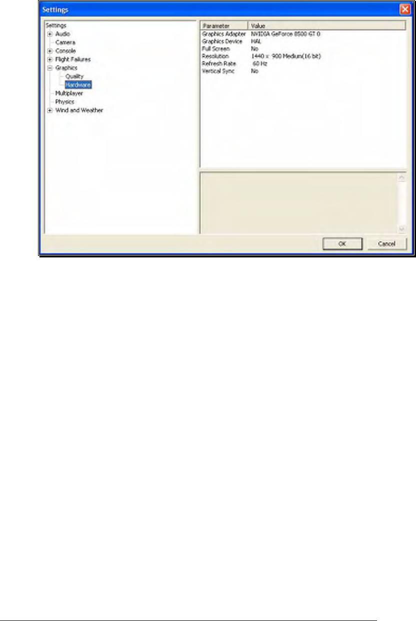
97
Graphics Adapter-
The Graphics Adapter is the device that RealFlight utilizes to run the
simulation, generically referred to as a video card. Most PC’s have
only one video card; however, some PC’s are equipped with multiple
cards.
To determine if your PC has an additional video card available to you,
click on the video card information located in the values column to the
right of the Graphics Adapter name. If multiple cards appear in the
drop-down selection there is another option for you. If not, your PC
is equipped with only one video card.
Graphics Device-
Some video cards offer multiple devices. HAL (Hardware Abstraction
Layer) is the preferred device to use for the graphics rendering. In
general, you should never need to modify this setting.
To determine if your PC offers alternative devices, click on the value
indicated in the column to the right of the Graphics Device name.
Full Screen-
This option determines whether RealFlight will run using the entire
monitor screen for the simulation. If you decide to run in the Full
Screen mode, RealFlight’s menus will not appear on the screen.

98
To access the menu while in Full Screen mode, press either the ESC
key or the ALT key on the keyboard.
To adjust the Full Screen option, click on the value as indicate in the
column to the right of the Full Screen name. From the pull-down
menu, select Yes to run in Full Screen or No to run in the Windowed
mode.
Alternatively, you may access the Full Screen mode by pressing the Alt
and Enter keys simultaneously on the keyboard. To exit Full Screen
mode, press the ALT and Enter keys simultaneously.
Resolution-
This control adjusts the screen resolution and color depth. If your
frame rate is unacceptably low, you can improve it by reducing the
resolution or color depth. This will reduce some of the rendering
processes required of your video card.
To adjust the resolution for your simulation, click the value indicated
in the column to the right of the Resolution name. Select the desired
level for your simulation from the drop-down list.
Please note: this option is only effective when using RealFlight in the
Full Screen mode.
We suggest that you test a variety of resolutions and color options to
achieve the optimum performance and setup for your system.
Refresh Rate-
The refresh rate is the number of times per second that your monitor
retraces its video display. Your video hardware (monitor and graphics
card) dictates what refresh rates you are able to utilize in the simulation.
As with Resolution, this option is only effective when running
RealFlight in the Full Screen mode.
To adjust the refresh rate, click the value that is indicated in the
column to the right of the Refresh Rate name. If there are multiple
options in this list, you might opt for a lower value to determine if this
improves the frame rate of your simulation.
Vertical Sync-
This option dictates where the monitor will draw the next vertical line.
Activating Vertical Synchronization slows the simulation slightly, but it
prevents the ‘tearing’ of on-screen images.
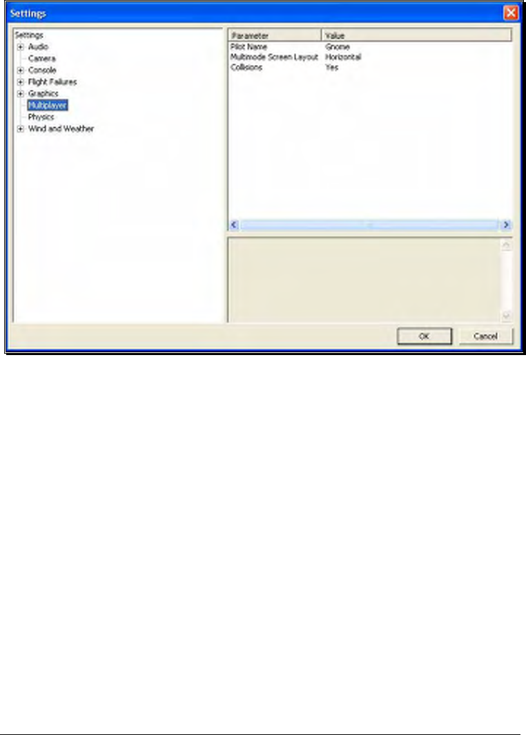
99
To adjust the Vertical Sync, click the respective value. Select Yes or
No from the pull-down menu that appears.
Multiplayer-
Settings available here effect multiplayer parameters, either in split screen MultiMode,
or over the internet.
Pilot Name-
This setting allows you to enter a name for the multiplayer sessions. To do so,
click on the value that appears to the right of the Pilot Name column. Click
the more options button (the gray folder with the ellipsis). Enter a name of
your choosing. When satisfied, press the Enter button on your keyboard.
Please note: when participating in a multiplayer session, other players may be
able to view the name you have selected.
MultiMode Screen Layout-
This setting specifies the layout of the screen for the MultiMode option. If you
select Vertical, the computer screen will split in half on its vertical axis. If you
select Horizontal, the computer screen will split in half on the horizontal axis.
To select which mode best suits your tastes, click on the value displayed to the
right of the MultiMode Screen Layout column. Next, select either Horizontal
or Vertical from the pull-down options.
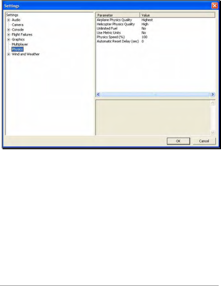
100
Collisions-
The Collisions options allows you to enable or disable the collisions between
aircraft in Multiplayer sessions. If you are connected via dialup, or have a slow
network connection, Select No as this may speed up the performance of the
simulator.
Physics-
The physics options are quite useful in fine-tuning the items applicable to the physics
of your simulated aircraft.
Airplane Physics Quality-
This setting determines the detail level of physics utilized for the airplanes in
the simulation. When the physics level is adjusted to the highest setting, the
simulation performs the aircraft calculations more accurately and more
frequently. Unless you are running the simulation on an older, slower PC, we
suggest using either the ‘high’ or ‘highest’ settings. Lowering the physics level
will reduce the quality and detail level used in the simulation, thereby allowing
the simulation to run at a faster rate for slower PC’s.
To alter the physics options, click on the value indicated in the column to the
right of the Airplane Physics Quality name. Using either the up/down arrow
keys on the keyboard, or the mouse, select the level for your simulation from
the pull-down list. If using the up/down arrow keys, press Enter to finalize
your selection.

101
Helicopter Physics Quality-
This setting determines the detail level of physics utilized for the helicopters in
the simulation. When the physics level is adjusted to the highest setting, the
simulation performs the aircraft calculations more accurately and more
frequently. Unless you are running the simulation on an older, slower PC, we
suggest using either the ‘high’ or ‘highest’ settings. Lowering the physics level
will reduce the quality and detail level used in the simulation, thereby allowing
the simulation to run at a faster rate for slower PC’s.
To lower the physics option, click on the value indicated in the column to the
right of the Helicopter Physics Quality name. Using either the up/down arrow
keys on the keyboard, or the mouse, select the level for your simulation from
the drop-down list. If using the up/down arrow keys, press Enter to finalize
your selection.
Unlimited Fuel-
This option determines whether or not your aircraft will run out of fuel. If you
select Yes, the engine will run indefinitely – assuming, of course, that you do
not crash. If you select No, the aircraft will indeed run out of fuel. The length
of time required to do so is based upon a number of factors including the
engine utilized and throttle management, just as it would at the flying field.
To determine whether your aircraft will run out of fuel, click on the value
column to the right of the Unlimited Fuel option. Using either the up/down
arrow keys on the keyboard, or the mouse, select either Yes or No from the
pull-down listings. If using the up/down arrow keys, press Enter to finalize
your selection.
Use Metric Units-
This option determines the unit of measurement for the various displays found
in the simulation. RealFlight defaults to display measurement in SAE units.
You can easily change this to use metric units.
To do so, click on the value column to the right of the Use Metric Units name.
Using either the up/down arrow keys on the keyboard, or the mouse, select
either Yes or No from the pull-down listings. If using the up/down arrow keys,
press Enter to finalize your selection.
Physics Speed-
Expressed as a percentage, this value controls the time scale of the simulation.
Reducing the value allows you to create a slow-motion effect. This is useful
when learning new skills or maneuvers, as you may slow the aircraft’s reaction
time.
It is important to note that these adjustments do not affect RealFlight during
multiplayer sessions or events.
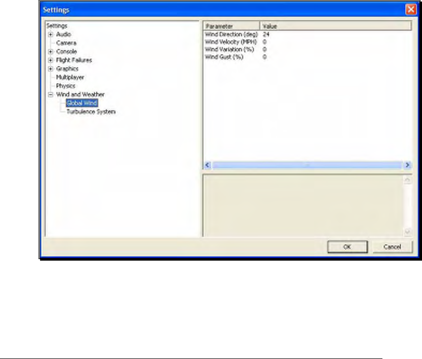
102
To adjust the Physics Speed, click the respective value. Enter the desired value
directly from the keyboard or use the mouse wheel.
Automatic Reset Delay (sec)-
This setting will force RealFlight to automatically reset the aircraft after a crash
where a piece of the aircraft has broken off.
To adjust the Reset Delay, click the respective value. Enter the desired value
directly from the keyboard or use the mouse wheel.
Wind and Weather-
The wind and weather options control the atmospheric conditions encountered in the
simulation. You can adjust these to match the conditions typically found at your local
flying site.
Global Wind-
These options determine the global wind conditions for the current airport.
Please note: the adjustments made here will temporarily override the airport’s
default values. Upon selecting an alternative airport or closing RealFlight, the
default values will be restored.
Wind Direction (deg)-
To adjust the wind direction, click on the value indicated to the right
of the Wind Direction name. Next, input a numerical value between 0

103
and 359 degrees to modify the wind direction. Alternatively, the
mouse wheel may be used to alter the input value.
You may also adjust the wind direction from the keyboard. Press the
Home key to increase the wind direction. The End key will reduce the
direction of the wind.
The direction that the wind comes from is expressed in degrees; where
0 is north, 90 is east, 180 is south and 270 is west. It is also possible to
adjust the wind direction to any angle in-between.
Wind Velocity (MPH)-
This setting adjusts the average winds that prevail over the entire
simulation. The velocity here is the speed of the wind approximately
6.5 feet (2 meters) above the terrain. RealFlight G4’s wind gradient
ensures that the wind below this level is slightly slower and that the
wind at higher altitudes is faster.
To adjust the wind velocity, click on the value indicated to the right of
the Wind Velocity (MPH) name. Next, input a numerical value
between 0 and 50, using either your keyboard or the mouse wheel.
This will be the wind speed in MPH.
You may also increase/decrease the wind velocity in smaller
increments by pressing the Page Up/Page Down keys on the keyboard.
Wind Variation (%)-
This adjustment represents the variation in the wind speed and
direction in correlation to the average speed. Just as the winds that
you experience at the local field are not constant, neither are the winds
in RealFlight.
To adjust this variable, click on the value indicated to the right of the
Wind Variation (%). Using either your keyboard or the mouse wheel,
input a numerical value between 0 (unchanging) and 200. A higher
value produces more dramatic changes in the wind.
Wind Gust (%)-
This value represents the change of the wind speed and direction
corresponding to a proportion of the wind speed it calculates in one
second.
To adjust this variable, click on the value indicated to the right of the
Wind Gust (%). Using either your keyboard or the mouse wheel,
input a numerical value between 0 (no changes) and 100 (large
changes).
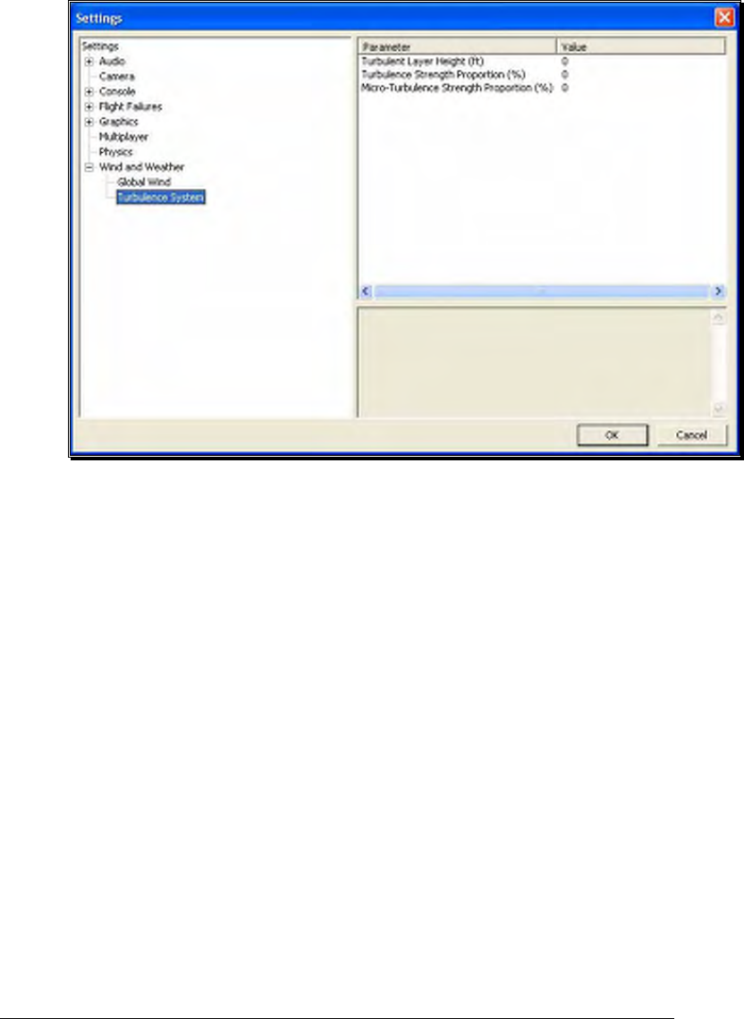
104
Turbulence System-
RealFlight’s wind model is so authentic that it even recreates the turbulence
which your aircraft will experience when out at the field.
Turbulent Layer Height-
Use this setting to mimic the turbulence level at your local flying site.
This setting represents the maximum height above the ground at
which your aircraft will experience the effects of G4’s turbulent winds.
To adjust the Turbulent Layer Height settings, click on the value
indicated in the column to the right of this respective option. The
desired values may be input directly from the keyboard or modified
using the mouse wheel.
Turbulence Strength Proportion (%)-
This option allows you to adjust the strength of the medium-level
turbulence. Since this setting represents a median, some turbulence
will be more severe than this, and some turbulence will be less
noticeable.
To adjust the Turbulence Strength Proportion (%) settings, click on
the value indicated in the column to the right of this respective option.
The desired values may be input directly from the keyboard or
modified using the mouse wheel. A value of 0% indicates that there
will not be any mid-level turbulence.
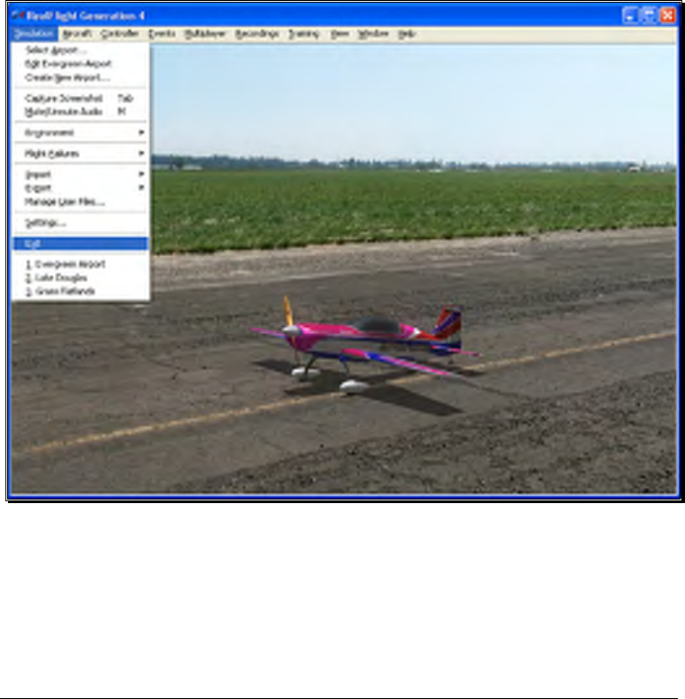
105
Micro-Turbulence Strength Proportion (%)-
This option allows you to adjust the strength of the lower level
turbulence. Some turbulence will be more severe. This is the lowest
level of turbulence that you will experience, however.
To adjust the Micro-Turbulence Strength Proportion (%) settings,
click on the value indicated in the column to the right of this respective
option. The desired values may be input directly from the keyboard or
modified using the mouse wheel. A value of 0% indicates that no
micro-turbulence will occur.
Exit
Use this menu item to exit the program entirely.
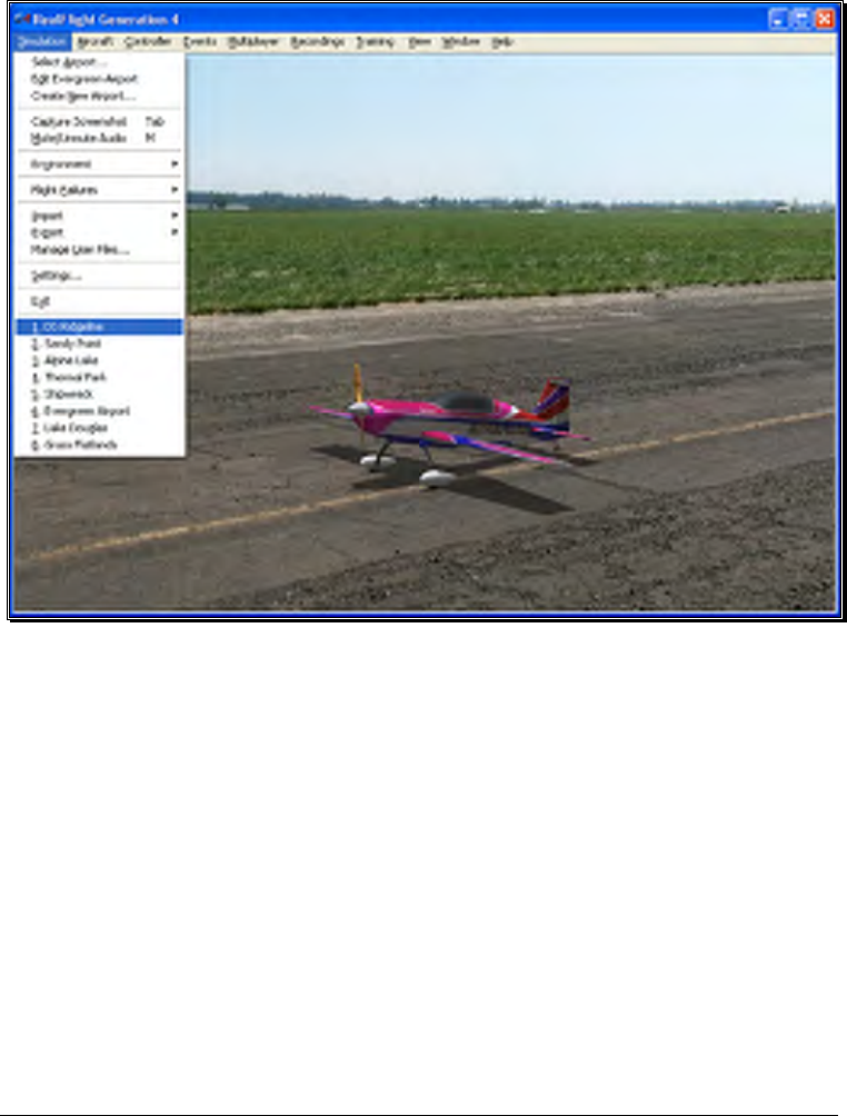
106
Airport MRU
If you have previously selected an alternative flying location, or locations, you will note
that it will appear on a list in the Simulation menu. This list is at the very bottom of the
menu and is commonly referred to as a Most Recently Used, or MRU list. It is limited
to the eight most recently selected locations. If you wish to fly at one of these locations
simply click on the respective location and it will begin loading.
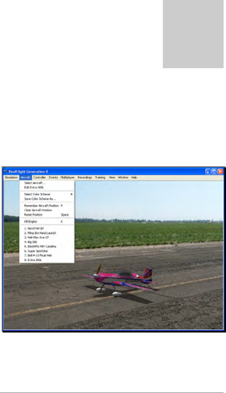
107
The Aircraft Menu
Offering access to a variety of aircraft related features, functions and options.
licking the Aircraft menu brings forth a pull-down menu similar to the
following screen shot.
The menu items that are available from the Aircraft menu include:
•
Select Aircraft…
Chapte
r
6
C

108
•
Edit Current Aircraft…
•
Select Color Scheme
•
Save Color Scheme As…
•
Remember Aircraft Position
•
Clear Aircraft Position
•
Reset Position
•
Kill Engine
•
Aircraft MRU
The following sections describe the function and purpose of each of these menu items.
Aircraft Selection…
When you click on Select Aircraft… the following dialog appears:
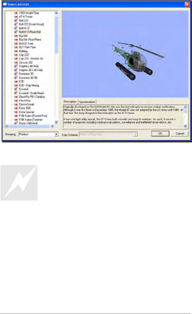
109
This dialog allows you to select the aircraft that you wish to fly.
Change aircraft simply by using the InterLink Elite. Press the
Menu/Select button, then, with the airplane tab highlighted press
the Menu/Select button again. This will bring up the Select
Aircraft dialog window. You can continue using the QuickSelect
buttons in this dialog to select a new aircraft, or press Reset to
resume flying without making any changes.
The list on the left of the dialog box displays all of the aircraft available to you. If you
have created any customized aircraft, they will also appear in this list.
By default, the aircraft are listed in files and directories in accordance with the software
from which they were loaded. If, for example, you have installed Expansion Pack 2,
the aircraft from this disc will be listed, alphabetically, beneath the Expansion Pack 2
directory.
Click the [+] (plus) or [-] (minus) symbol to reveal or hide the aircraft within these
directories and folders.
Aircraft Selection
Every aircraft has its own unique flying characteristics, special features and functions.
To view an aircraft from the listings, simply use the mouse to click on the aircraft name.

110
Alternatively, use the up/down keys on the keyboard to scroll through the list, one
aircraft at a time.
The first time an aircraft is selected, G4 creates a collision mesh for the aircraft. This
process may take a few seconds to complete. A progress bar will appear while the
collision mesh is being calculated.
Click the [+] (plus) symbol to reveal the aircraft contained within the folder. Using
either the up/down arrow keys on the keyboard or the mouse, select the desired
aircraft from the listings. If utilizing the up/down arrow keys, click OK to finalize your
selection. Alternatively, if using the mouse, double-click on the aircraft to load it.
Have some fun while you’re in the Select Aircraft dialog. Using the mouse, click and
drag the preview screen to point the camera angle to your choosing. Use the scroll
wheel to zoom in or out. Or, move the gimbals to see the control surfaces move. To
resume rotating automatically, right-click the preview screen.
Description/Specifications-
The pane below the Aircraft Preview box shows either the aircraft description or
aircraft specifications. This box provides you with a brief history of the aircraft (if
applicable) and serves to provide you with specific information pertaining to the model
selected.
Using the mouse, select either the Description or Specifications tab.
Grouping-
This list controls how the dialog organizes the list of available aircraft. By default, the
aircraft are sorted by Product. Here is an explanation of the different sorting methods:
Product, Airframe: Aircraft are grouped first by which product they are found in (all
custom aircraft will be in the “Custom Aircraft” folder). Within each product, the
aircraft are further grouped by airframe. For example, “NextSTAR” and “NextSTAR
with AFS” are both found in the NexSTAR airframe folder.
Product: Aircraft are grouped by product alone.
Airframe: Aircraft are grouped by airframe, not by product. Individual aircraft are
grouped inside each airframe folder.
None: There is no grouping at all. All aircraft are sorted alphabetically.
Color Scheme-
If applicable, this list contains the alternative trim schemes for the selected model. If
the Color Scheme dialog is grayed out, there are no alternative trim schemes available
for this particular aircraft.

111
If the list control is active, click on the down arrow to reveal the alternate trim
scheme(s). To select an alternate trim scheme, use either the up/down arrow keys on
the keyboard or select one with the mouse. When an alternative trim scheme is
selected, this scheme will appear immediately in the ReadySelect preview box, replacing
the previous trim scheme.
Additionally, modelers may create their own trim schemes in RealFlight using a third-
party bitmap editor capable of manipulating Targa (*.tga) files. Please see the section
titled “Save Color Scheme As….”.
Edit Current Aircraft
RealFlight G4 offers the user unparalleled freedom to edit or modify their aircraft. It’s
possible to add and remove components, alter their location, change airfoils and much,
much more! The first several times that you access the aircraft editor, the task might
seem daunting. It may require some getting used to before you are comfortable with
this feature and its related functions. The best way to do so is to simply dive in and
experiment.
To modify the currently selected aircraft, click the Aircraft menu followed by the Edit
Current Aircraft
menu item. This brings up the Aircraft Editor dialog, which will
allow you to modify any of the hundreds of parameters for the currently selected
aircraft.
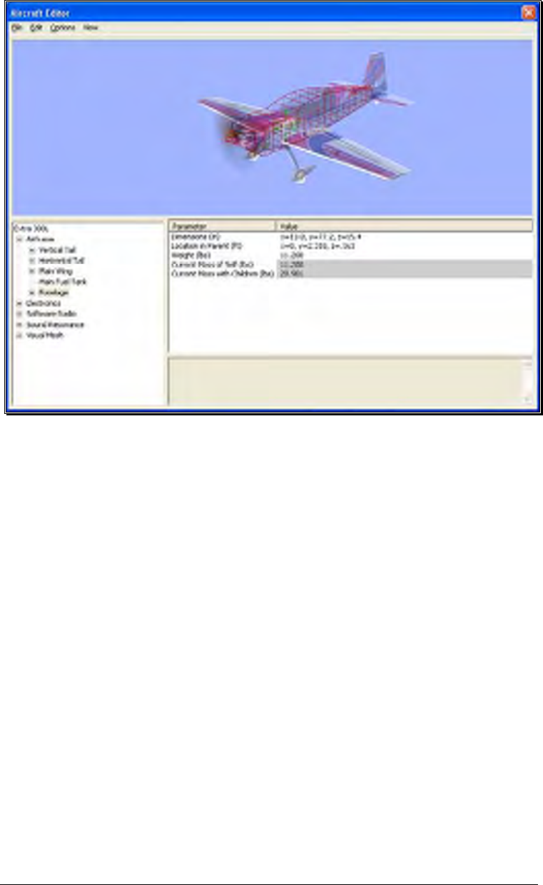
112
The Aircraft Editor dialog will have an appearance similar to the screen shot shown
below. It may deviate slightly depending upon the type of aircraft that you are editing
(i.e., biplane, electric model, etc.). However, all aircraft are edited in a similar manner.
As such, this section presents you with the general information necessary to edit any
aircraft found in G4.
Aircraft Editor Menus-
Selecting the Edit Current Aircraft option activates the screen shown above. The
Aircraft Editor dialog has three menu options:
• File
• Edit
• Options
• View
File Menu-
This menu and its menu items are used to manipulate and control the various
folders and related items in the aircraft editor.
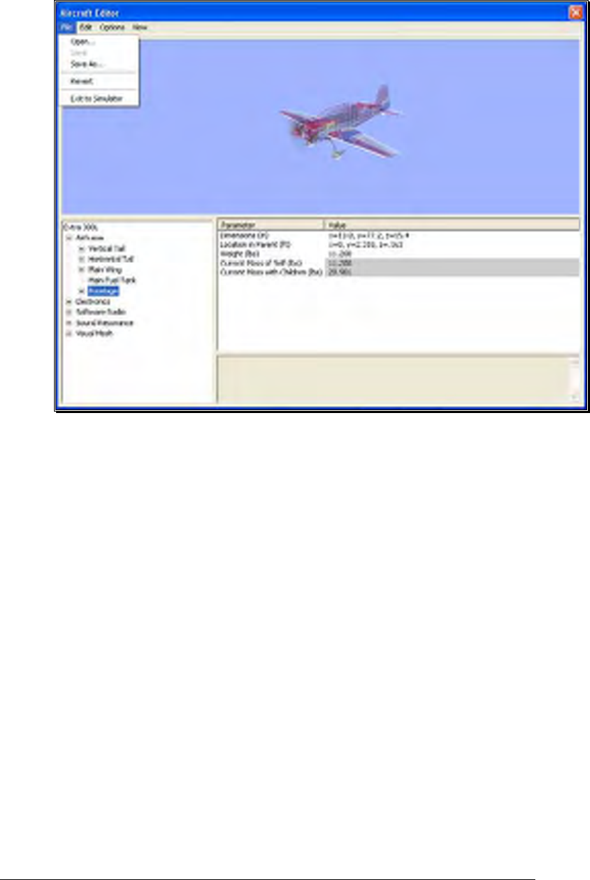
113
Open…-
This menu item is used to open existing and edited aircraft. Selecting
this menu item opens the Select Aircraft dialog. To select an aircraft
from this list, follow the procedure described in the Aircraft Selection
section of this manual.
Save-
This option becomes active once you have renamed and saved the
edited aircraft. Prior to doing so this option will remain inactive or
grayed out. This allows you to make further modifications to the
aircraft without renaming it each time.
Save As…-
Upon completion of the aircraft editing, click this menu item to
rename and save the modifications. You will be asked to create a
name for this new aircraft. After you have renamed the aircraft, click
OK to accept the new name. Afterwards, the aircraft will appear in
the aircraft listings found in the Select Aircraft… in the Aircraft menu.

114
Revert-
This menu item allows you to revert, or go back to the settings the last
time that the aircraft was saved. If you have not previously saved the
aircraft, the aircraft will return to the default settings.
To use this menu item, open the File menu and click Revert. This
will bring forth the verification dialog.
Click Yes if you wish to return to the last saved version of this model.
Please note: any modifications performed after the last time that this
model was saved will be lost. Clicking No will allow you to save the
modifications or continue refining the aircraft.
Exit to Simulator-
This menu item returns you to the simulation. If you have performed
any modifications to the aircraft and have not saved these
modifications, a verification dialog will appear. Choose Yes to save
the modifications. If you select No, the modifications will be lost.
Selecting Cancel will return you to the editing dialog.
Edit Menu-
As is suggested by the name, this menu is utilized to edit the aircraft. The
available options depend upon which item or folder is highlighted in the
directory. If you have not highlighted an item or folder, the Edit menu will
remain grayed out or inactive.
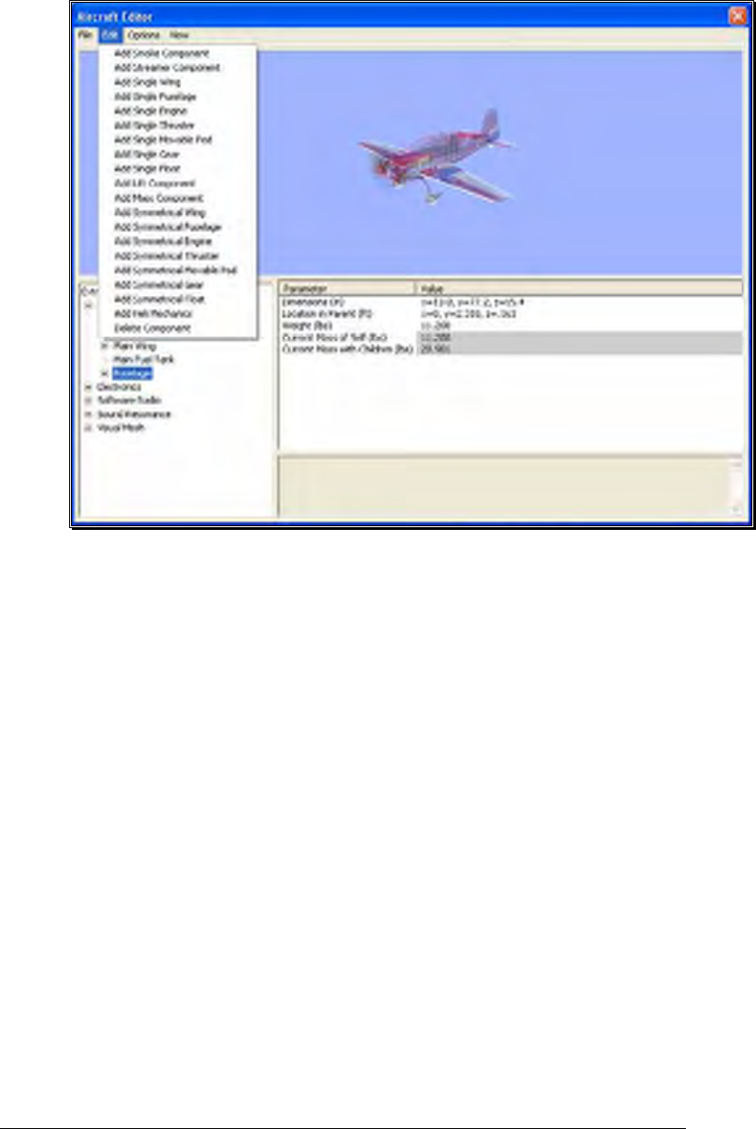
115
For example, if the aircraft name is highlighted and the Edit menu is selected,
there will not be any actions available to you. If the airframe is highlighted, the
aircraft editor will allow you to add various components to the airframe.
Alternatively, if you wish to either add or remove an item from one of the
aircraft components, right-click on the respective component. This will bring
forth the available options.
When editing aircraft, you can click and drag the mouse in the preview area to
rotate the aircraft to different angles. This helps to better see components you
might be modifying.
Options Menu-
This menu provides you with a number of choices, or options, available to you
for use in the aircraft editor.
Selecting the Options menu brings forth the drop-down menu items discussed
below.
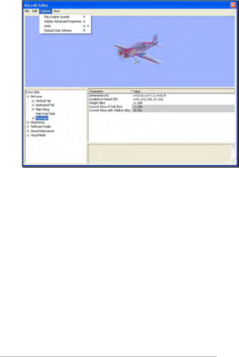
116
Play Engine Sounds-
Selecting this menu item plays the respective engine sounds during the
editing of this aircraft. Please note: this setting is only temporary.
That is, this setting is not retained after you exit the aircraft editor.
To select this option, click the Play Engine Sounds menu item. This
will place a check mark before the setting and return to the aircraft
editor. Additionally, the engine sounds will become audible.
Additionally, you may also press the ‘P’ key on the keyboard to enable
or disable the engine sounds.
Display Advanced Properties-
This option displays advanced properties for the components in the
airframe. Using the advanced properties you may fine-tune the physics
calculations performed by RealFlight, in order to adjust the flight
performance to your liking. When this option is checked, additional
component properties will be displayed in the property listing area of
the aircraft editor dialog. These properties are marked as “Advanced”
in the following sections.

117
Additionally, you may also press the ‘D’ key on the keyboard to display
or eliminate the advanced properties from the dialog.
Units-
This option toggles the units of measure between metric and SAE
units. It is important to note that modifying this option affects all
measurements in the simulation. For example, changing from SAE to
metric in the editor also affects the airport editor dialogs.
To modify this option, click the Display Metric Units setting. Then
select the unit of measurements you would prefer from the drop down
menu. The options are English or Metric. A check mark will appear
next to the unit that is currently displayed.
Alternatively, you can press the ‘U’ key on the keyboard to switch
between the different units of measurement.
Reload Color Scheme-
This option allows you to view the results of an edited trim scheme.
There are two ways that you can do so. The first is to use the Select
Color Scheme menu, which is found within the Aircraft menu.
Simply click on the color scheme that you have just edited, and
RealFlight will reload the color scheme onto your aircraft and reset the
aircraft back on the runway.
Alternatively, within the aircraft editor, click on the Options menu
item. Select Reload Color Scheme. Clicking this reloads the color
scheme, showing any changes you have made to the aircraft. To
improve visibility of the trim scheme, you may wish to remove the
wireframe from the preview. To do so, please follow the procedure
noted in the description for “Show Wireframe.”
You can also press the ‘R’ key on the keyboard to reload the color
scheme.
View Menu-
The View menu in the aircraft editor offers choices on the perspectives of the
aircraft in the preview window.
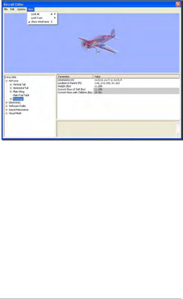
118
Look At-
This option allows you to determine the view of the aircraft being
edited. There are three options available from this menu.
• Aircraft Center- Check this option is you wish to keep the entire
aircraft centered in the view.
• Component Center- Check this option to center the view around
the component you are editing. For example, if you are modifying
the rudder, the aircraft will shift so that the rudder appears in the
center of the preview area.
• Component Origin- Checking this option will focus the view on
the root, or origin, of the component you are currently modifying.
For example, if you have the Main Gear selected, the preview area
will be centered at the location where the Main Gear is attached to
the fuselage.
To adjust the Look At perspective, click the Look At menu item and
select the desired view. Alternatively, you may use the ‘A’ key on the
keyboard to toggle through the selections.

119
Look From-
Alternatively, you can select from pre-determine angles from the Look
From menu item. They include:
• Above – Look from above the aircraft. Or press the Q key to
quickly change to this view.
• Below – Look from below the aircraft. Or press the Shift-Q keys
to quickly change to this view.
• Right – Look from right side the aircraft. Or press the W key to
quickly change to this view.
• Left – Look from left side the aircraft. Or press the Shift-W keys
to quickly change to this view.
• Front – Look from the front of the aircraft. Or press the E key to
quickly change to this view.
• Back – Look at the back of the aircraft. Or press the Shift-E keys
to quickly change to this view.
Show Wireframe-
This option determines whether the aircraft displayed in the preview
box is shown as a wireframe or is rendered complete with textures, etc.
The wireframe option is automatically selected by default.
If you would prefer to view the fully rendered image, click the Show
Wireframe option from the pull-down list. This will eliminate the
check mark from the setting and return to the aircraft editor.
Additionally, the preview aircraft window will show the rendered
image of the aircraft.
Alternatively, you may press the ‘S’ key on the keyboard to display or
eliminate the wireframe view.
Aircraft Parts Tree-
The bottom half of the Aircraft Editor contains three important areas; the Aircraft
Parts Tree, Parameter window, and the description pane.
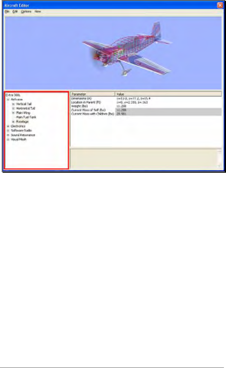
120
The Aircraft Parts Tree breaks down the entire list of aircraft components and radio
data into an easy-to-use hierarchy.
The first item listed is the name of the aircraft you are currently editing, and is
considered the root item for all other items listed here. Selecting it will offer a variety
of common parameters that you can edit in the Parameter window. These include the
description of the aircraft, Launch Method, Power Plant Type and Radio Type.
Below the aircraft name, there are additional options that allow you to customize the
individual parts of the aircraft. You also have the ability to modify the electronics and
radio program for the aircraft.
Each part belongs to a higher component, or parent, with the root being the highest
component. In return, it’s possible that the part itself also has children parts that
belong to it. For example, if you wish to edit the wheel size on the P-51, you will find
it under the following path in the Aircraft Parts Tree:
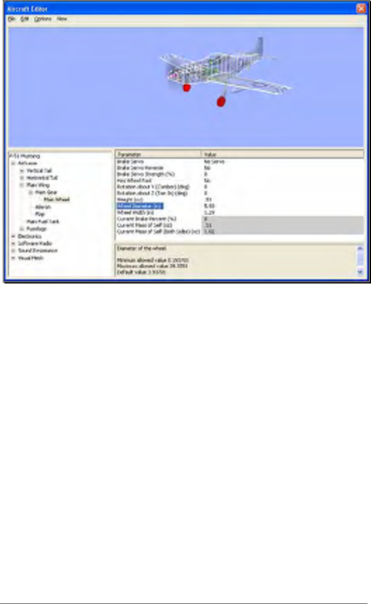
121
• P-51 Mustang - root of the aircraft, found at the top of the Aircraft Parts Tree list
o Airframe – Contains all the physical parts of the aircraft, like wings,
fuselage, etc.
Main Wing – One of many physical parts found in the Airframe
• Main Gear – The Main Gear on the P-51 attaches to the
wing, therefore, we found it under the Main Wing part.
o Main Wheel – Finally, you’ll see the wheel
component which, understandably, is found
under the Main Gear part.
Once the Main Wheel is selected, the Parameter window will change to show all
parameters available to the Main Wheel. You’ll notice that one of these parameters is
wheel diameter.
All other parts are found and modified in much the same way. If, however, you are
unsure as to the location of a part, an easier way to access the part is to click on the
desired item in the Preview screen on the top half of the window. For example, if you
want to modify the parameters for the horizontal tail of the P-51, simple click on that
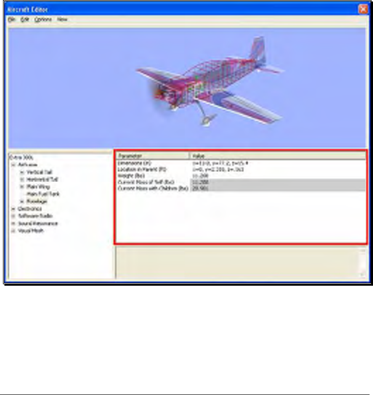
122
portion of the image. You’ll notice that the Horizontal Tail is now selected in the
Aircraft Parts Tree.
Preview Screen-
As mentioned above, to quickly find the part in the Aircraft Parts Tree for
modification, you can simply click that part in the Preview screen itself. At times, you’ll
notice that the part you want to click might be hidden behind another section of the
aircraft. If you find yourself in this situation, click and drag the mouse cursor around
the Preview screen. This will rotate the aircraft image around so you may view it from
different angles. You may also use the scroll wheel on the mouse to zoom in and out
for a closer look at the section you are working on.
Parameter Window-
On the bottom half of the Aircraft Editor, you will see the Parameter window on the
right side. This window will list all the parameters available for the currently selected
part in the Aircraft Parts Tree.
Clicking on the parameter will allow you to view a description of its use in the
Description pane directly below the Parameter window. This will also allow you to
modify the currently selected parameter.

123
Add and Removing Components-
There are times when you may want to add a new component to the aircraft. The first
step is to determine the location for the new part. For example, if you were to add
flaps, it makes more sense to add it to the main wing, than to the fuselage.
After having determined the location for the new part, you can add it in one of two
ways. Select the new part from the Edit menu. Alternatively, you can right-click on
the component in which you are adding the new part. Again, if you were adding flaps,
right-click on the Main Wing component, then select Add Control Surface.
Removing a component works in much the same way. In the Aircraft Parts Tree,
select the component you wish to remove. Then select Delete Component from the
Edit menu. Alternatively, you can accomplish the same thing by right-clicking on the
part to remove and selecting Delete Component.
More Information-
The Aircraft Editor may seem a little overwhelming at first. The best way to become
familiar with the editor and its related functions is to simply use it and start
experimenting. RealFlight does not allow you to customize the stock aircraft. As such,
if you make a change to one of the stock aircraft, you will be forced to save it under a
new name. Therefore, you always have the stock aircraft to default to, should the need
arise.
Our online forums and swap pages provide a great source of information, and
assistance from other RealFlight users. These pages may be found at:
http://www.knifeedge.com/forums/
Select Color Scheme
This menu item allows you to choose an alternative trim scheme (if available) for the
current aircraft.
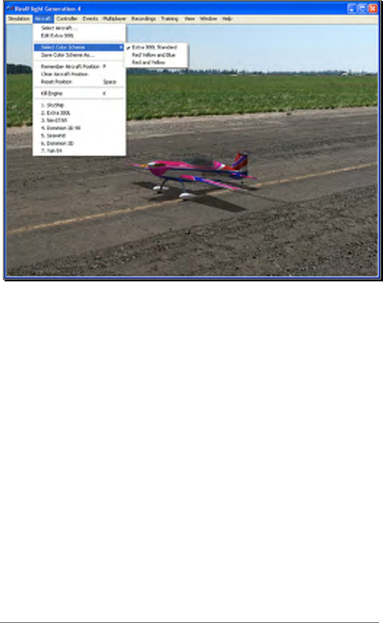
124
To view the alternative color schemes, click the Select Color Scheme menu item. To
select an alternate trim scheme, click the existing selection in the value box. This will
bring forth the pull-down menu selections. Use either the Up/down arrow keys on
the keyboard, or the mouse to select the desired option. If utilizing the arrow keys,
press Enter to finalize the selection. The new trim scheme will appear immediately on
the aircraft. Please note: if only one scheme appears in the pull-down menu,
alternative schemes are not available for this aircraft.
Save Color Scheme As…
This menu item is used to create an editable version of the currently selected trim
scheme.
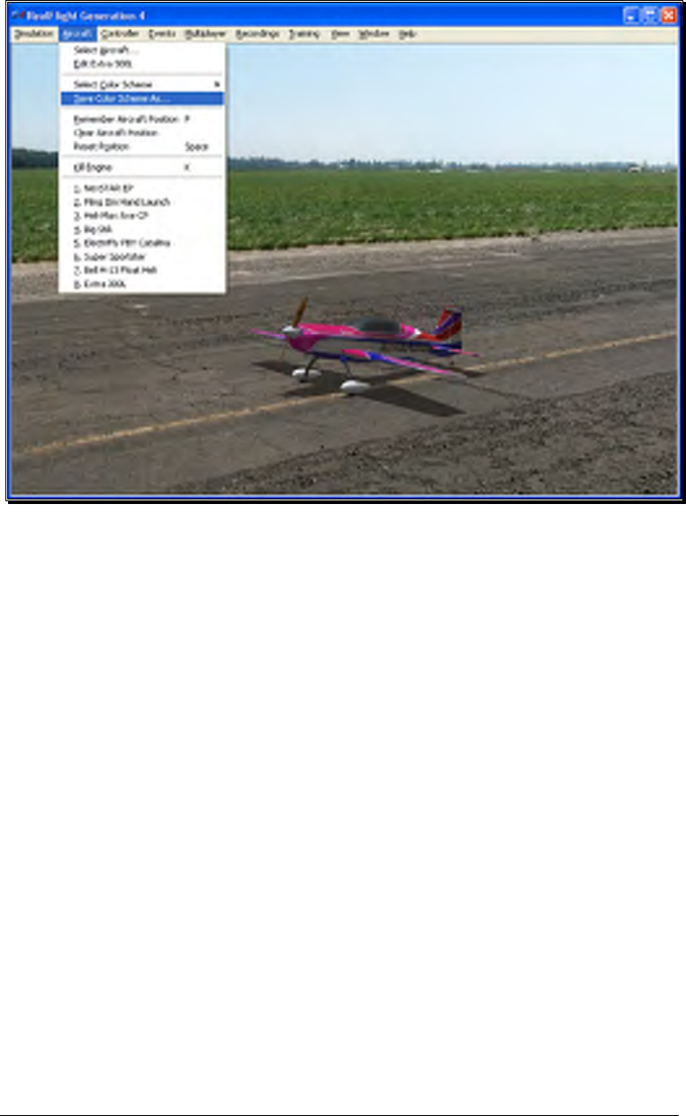
125
RealFlight G4 allows you to create a custom paint/decal scheme for your aircraft. The
color schemes you create are limited only by your imagination.
However, only individuals that own, and know how to use, a third-party bitmap editing
program such as Adobe® Photoshop®, should attempt to create a custom color
scheme. Your editor must be able to read and edit Targa (“.tga”) files.
To create a custom color scheme click the Save Color Scheme As… menu item.
Enter the desired name in the dialog box that appears. The location of the file will
appear in the lower left corner of the RealFlight screen.
To access the file that contains the custom color scheme, open the My Documents
folder. Next, open the RealFlight G4 folder followed by the Vehicles folder. A
number of folders are available here, open the folder called ColorSchemes. This will
bring up all of the custom color schemes that have been stored in RealFlight. The
name of the aircraft will precede the name that you have selected for your custom
color scheme. Click on the file for which you wish to modify the trim scheme.
DO NOT ALTER THE NAME OF THIS FILE, AS REALFLIGHT MAY
NOT BE ABLE TO CORRELATE THE COLOR SCHEME WITH THE
AIRCRAFT.

126
Once you have finished editing and saving your color scheme, you will probably want
to see the results of your work. There are two ways that you can do so. One is to use
the Select Color Scheme menu, which is found within the Aircraft menu. Simply click
on the color scheme that you have just edited, and RealFlight will reload the color
scheme onto your aircraft and reset the aircraft. Within seconds, you are ready for
flight with your new color scheme.
Alternatively, access the Aircraft Editor (see section Edit Current Aircraft on page 111).
Within the aircraft editor, look for Reload Color Scheme which is located in the
Options menu. Clicking this will reload the color scheme, showing any changes you
have made to the aircraft. You can disable the wireframe using the Options menu to
improve your view.
While looking in the ColorSchemes directory for your new color scheme, you may also
notice a “.colorscheme” file with the same name as the “.tga” file. This file can be
opened in a text editor such as Notepad. Within the file, you will find six values to edit:
Specular, Reflectivity, PowerSpecularOff, PowerSpecularOn, PowerReflectiveOff, and
PowerReflectiveOn.
Specular - A multiplier for the overall specularity of the aircraft. Specular=1 is neutral,
Specular=0 disables specular highlights.
Reflectivity - A multiplier for the overall reflectivity of the aircraft. Reflectivity=1 is
neutral, Reflectivity=0 disables reflections.
Specular highlights vary from fully off to fully on as the specular power of each piece
of the aircraft goes from the value PowerSpecularOff to PowerSpecularOn.
Reflections vary from fully off to fully on as the specular power of each piece of the
aircraft goes from the value PowerReflectiveOff to PowerReflectiveOn.
Tips for Color Schemes
• A quick and easy way to change a color scheme is to replace one color
with another. Photoshop has a command that can easily do this called
“Replace Color”.
• Make sure you save the file as 32 bit TGA files so that the Alpha Channels
are preserved (See below).
• You are only allowed a single Alpha Channel.
• Do NOT alter the resolution of the image.
• Other formats (JPG, BMP, etc) are not allowed.
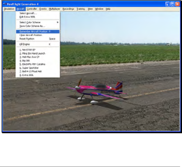
127
Alpha Channels
Almost all of the color schemes for the aircrafts incorporate an Alpha Channel, which
defines what areas of the color scheme are opaque and what areas are transparent.
White portions of the alpha channel will be 100% opaque and Black portions of the
alpha channel will be 100% transparent. Shades in-between will be partially transparent.
Consult the image editor’s manual to determine how to use Alpha Channels.
Note: RealFlight uses TGA files instead of the BMP format. This is because BMP formats do not
support alpha channels.
Remember Aircraft Position
The Remember Aircraft Position menu item saves the current position of the aircraft.
When you reset the aircraft, it will return to the same position (speed, attitude, heading,
etc.) as when this menu item was selected. This feature is ideal for practicing
maneuvers, such as an autorotation in a helicopter.
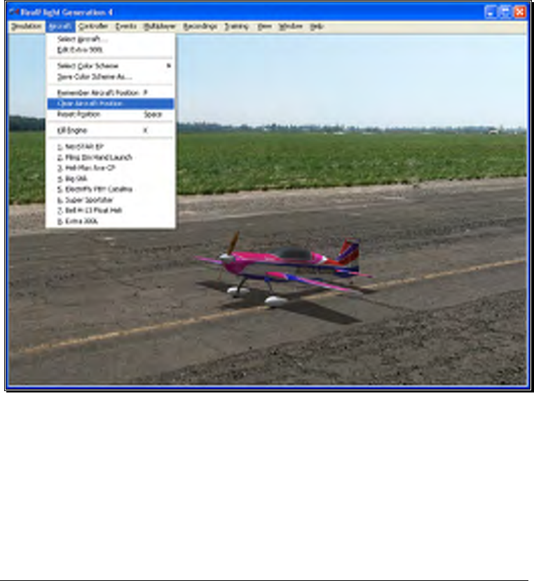
128
To activate this menu item, click the Remember Aircraft Position menu item when
the aircraft is in the desired location and altitude. Alternatively, pressing the ‘P’ key on
the keyboard will also remember the aircraft’s position.
Each time the aircraft is reset it will begin flight from the saved location. Please note:
the saved position is only temporary. If you select another airport, aircraft, or if you
exit the simulation and restart, you will need to save the desired position once again.
Clear Aircraft Position
This menu item clears the position saved in the Remember Aircraft Position without
exiting the simulation, changing flying sites and/or aircraft.
To do so, simply click the Clear Aircraft Position menu item. When the aircraft is
reset, it will return to one of the default starting positions.
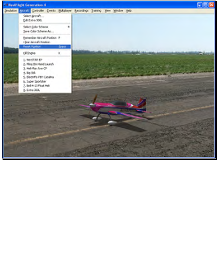
129
Reset Position
There are three ways to reset the aircraft to its takeoff position:
1. Press the Reset button on the InterLink Elite controller. This is probably the
fastest and simplest method.
2. Press the keyboard’s space bar.
3. Click the Reset Position menu item.
Kill Engine
Click on this item to instantly stop the motor from running. This is useful when you
are practicing dead-stick landings in airplanes and when practicing autorotations for
helicopters. Alternatively, you may also press the keyboard’s ‘K’ key.
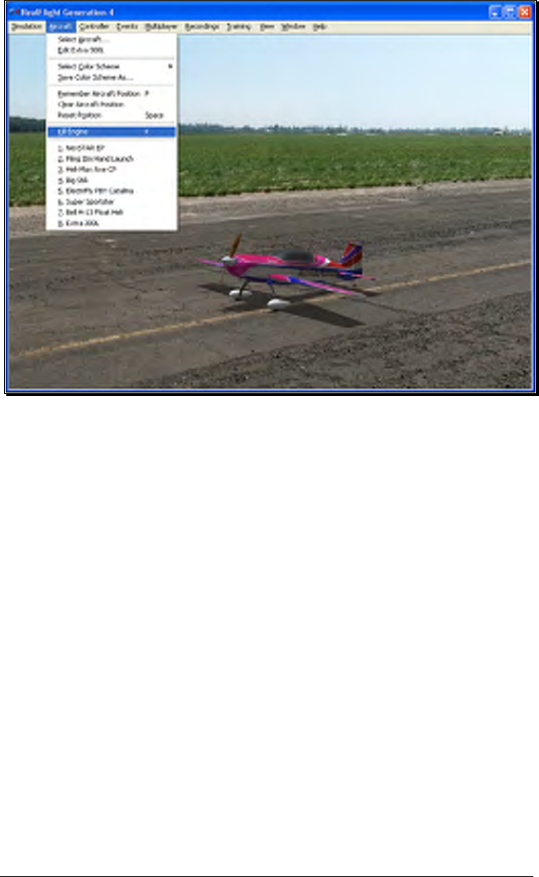
130
Aircraft MRU
The final items in the Aircraft menu indicate the most recently used aircraft. The first
item is the aircraft that you are currently flying; successive items are aircraft you have
previously flown. The MRU shows only the eight most recently selected aircraft.

131
You can load an aircraft by selecting it from this list. This shortcut allows you to
switch between your favorite aircraft without using the Select Aircraft dialog.
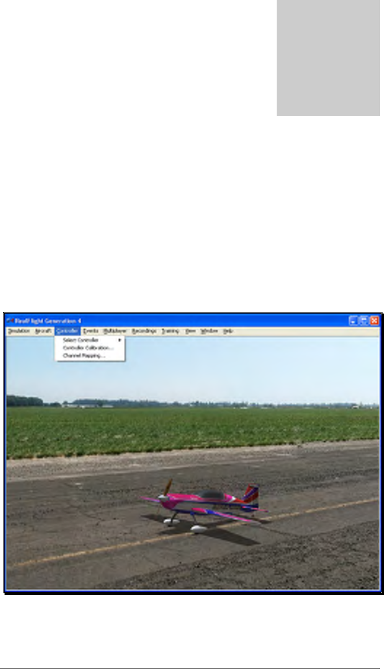
133
Controller Menu
Determine the method of control, map the channels to your liking, and calibrate
the controller.
he Controller menu allows you to select the method of control, calibrate the
controller and to map the channels for your desired method of control for
RealFlight G4.
When you click the Controller menu, a screen similar to that below will appear:
The menu items available are:
Chapte
r
7
T
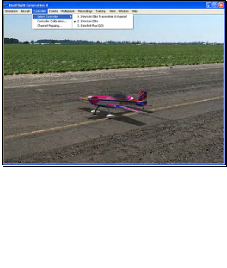
134
• Select Controller
• Controller Calibration…
• Channel Mapping…
Select Controller
When you click on the Select Controller menu item, the following sub-menu appears:
To choose the method of control, click on the Select Controller menu item from the
Controller menu. The selection(s) will vary depending on whether or not you have
attached an actual R/C transmitter to the interface adapter for the InterLink Elite.
Please note: if you have attached a controller to the InterLink Elite’s interface port,
RealFlight will pause briefly while it detects the transmitter.
The selections are (usually) InterLink Elite and InterLink Elite Transmitter X Channel.
If you will be using your own controller in the simulation, choose the InterLink Elite
Transmitter
X
Channel. The sections that follow will explain the differences
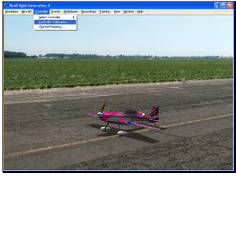
135
between the various modes and methods of control and the means and ways to access
and utilize them.
If you have attached a Generation 2 InterLink controller or a G3 InterLink Plus
controller in addition to the G4 InterLink Elite, there will be an option allowing you to
select these controllers as well.
Controller Calibration
The Controller Calibration… menu item allows you to adjust your controller for use
in the simulation. Calibration is the method of fine-tuning the controller input for the
simulation, so that you will achieve the desired responses.
Once selected, the following screen appears:
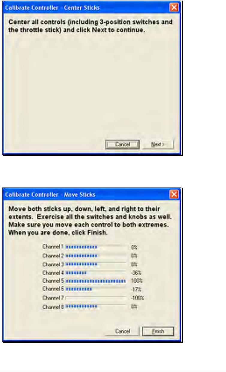
136
As directed, place all sticks, knobs and switches to their center positions. Click Next
when finished.
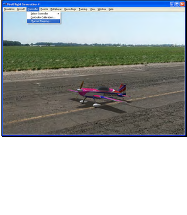
137
It is imperative to move all of the sticks, knobs and switches through their complete
range of motion several times. This is the key to a properly calibrated controller.
When completed, click Finish. You will now be returned to the simulation with a
calibrated controller.
Channel Mapping…
G4’s Channel Mapping feature allows for incredible flexibility and adjustability
regardless of radio manufacturer or flight mode utilized. This menu item enables you
to define the functionality of the transmitter when utilized in the simulation.
To access the Channel Mapping… menu item, click the Controller menu. Next, select
the Channel Mapping… option. This will bring forth the following screen.
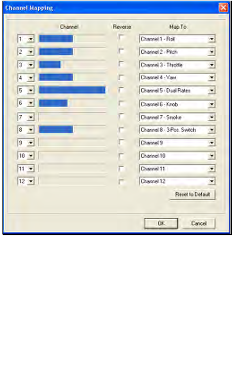
138
It is important to have a basic understanding of the Channel Mapping… screen prior
to actually modifying the actual mapping itself.
Channel-
This column corresponds to the actual channel of the transmitter used to control the
functionality, as defined in the Map To column.
For example, radio channel 3 on a Futaba radio corresponds to the throttle. As such,
the Map To value is defined as throttle. On the other hand, radio channel 3 on a JR
radio controls the pitch (elevator).
The first column displayed shows the number for the input channel. You can change
this by clicking the down arrow next to the number and selecting a different channel.
This is useful if you want the same channel to control multiple functions. For example,
with this option you could assign channel 3 to control both throttle and elevator. It’s

139
important to note that this will affect all aircraft. See Edit Current Aircraft on page 111
for information on how to edit the individual aircraft.
The radio channel values serve as placeholders, or reminders, for the functionality of
your transmitter with regards to the Map To functions.
Map To-
The values here define the function or duties that will be performed by the transmitter.
Using the example from the Radio Channel above, the Map To for Futaba’s Channel 3
dictates that this will control the throttle of the desired aircraft. For JR radios, Channel
3 on the transmitter controls the pitch (elevator).
If your transmitter varies from the default definitions, it is necessary to modify the Map
To functions. To do so, click on the Map To channel that corresponds to the channel
you wish to adjust. Using either the up/down arrow keys on the keyboard or the
mouse, select the desired Map To channel. If using the up/down keys, press Enter to
finalize your selection.
If the channels are mapped, or defined properly but control input produces results that
are backwards (e.g., increasing the throttle stick actually decreases the throttle on the
aircraft), please refer to the Reverse Channel section that follows.
Reverse Channel-
The value here determines whether to reverse the input received from the radio
channel. If checked, the input will be reversed.
To adjust the input direction, click on the corresponding Reverse Channel checkbox
as necessary.
Using RealFlight’s Channel Mapping-
Now that you have a basic understanding of the Channel Mapping, it is time to utilize
this knowledge to program the software for your controller.
While watching the channel values, move the gimbal stick that controls the throttle
input for your aircraft. Taking note of the value, map this channel to the throttle.
Repeat this procedure for ALL corresponding channels on the transmitter. When you
have finished, click OK. Next, return to the simulation and test the Channel Mapping
to ensure that all channels are mapped correctly and that all function as desired. If not,
please return to the Channel Mapping…menu item and refine accordingly.
After you have correctly mapped the channels, it is best to re-calibrate your transmitter.
To do so, please see the Controller Calibration section on page 135.

140
Joystick Mode vs. Transmitter Mode
In single-player mode, RealFlight allows you to quickly and easily change the method
used to control the action in the simulation. RealFlight G4 offers two control modes:
• Joystick Mode. Using the InterLink Elite in Joystick Mode, RealFlight G4 accepts
control input from the sticks, switches, knob and push-button on the InterLink
Elite controller. This is the default mode when you install RealFlight. Again, we
suggest that you fine-tune the calibration of the controller. For information on
how to do so, please refer to the Controller Calibration section on page 135.
• Transmitter Mode. Using the InterLink Elite in the Transmitter Mode, RealFlight
G4 accepts commands from your actual R/C transmitter. To use this mode, your
transmitter must be connected to the InterLink Elite controller via the InterLink’s
built-in interface. This is an optional use of the InterLink, and we have provided
the necessary cables for using most popular R/C transmitters. Using the
Transmitter Mode takes slightly more setup and understanding of your radio than
does using the Joystick Mode.
• To switch between these modes, highlight the Select Controller menu item. The
InterLink Elite controller will automatically test to determine whether an R/C
transmitter is present. After the detection testing completes, select the mode that
you wish to utilize for your flight -- either Transmitter Mode or Joystick Mode.
Regardless of which mode you select, you will return to the simulation and be
ready to start flying immediately.
InterLink Elite Controller (Joystick Mode)
In Joystick Mode, RealFlight accepts control input from the sticks, switches, rotary
knob and push-button found on the InterLink Elite controller. This is the default
mode when you install RealFlight G4.
The RealFlight G4 software, working in conjunction with the InterLink Elite controller,
actually does all the radio processing to measure the raw stick, switch, knob and push-
button input from the controller. It then processes this input to produce the servo
outputs that are used to control the aircraft.
Helicopters, for example, ordinarily require a great deal of mixing to achieve flight.
This mixing is normally the function of a computer radio. When RealFlight G4 uses
the Joystick Mode, the mixing is done by the RealFlight G4 software itself and not by
the InterLink Elite controller.

141
Channel Modification-
It is possible to modify the mixing of the radio in the Software Radio menu. To access
the Software Radio menu, click the Aircraft menu followed by the Edit
Current
Aircraft
menu item. Next, click on the Software Radio menu.
Every aircraft in RealFlight has its own unique software radio program that maps
(converts) the raw stick inputs from the InterLink Elite controller into the correct
servo input for that particular aircraft.
Controller Calibration-
Occasionally it may become necessary to fine-tune your InterLink Elite controller’s
calibration. To do so, click on the Controller menu followed by the Controller
Calibration… menu item. Follow the directions that appear on-screen to complete
the calibration procedure.
Stick Mapping
As noted above, RealFlight’s Channel Mapping… feature allows you the flexibility to
modify the operational mode of the transmitter. Typical operation modes are as
follows:
• Transmitter Mode 1 (Europe, Asia) - Mode 1 transmitters have aileron and throttle
on the right stick, and rudder and elevator on the left stick.
• Transmitter Mode 2 (USA) - Mode 2 transmitters have aileron and elevator on the
right stick; rudder and throttle on the left stick.
• Transmitter Mode 3 - Mode 3 transmitters have rudder and elevator on the right
stick; aileron and throttle on the left stick.
• Transmitter Mode 4 - Mode 4 transmitters have rudder and throttle on the right
stick, and aileron and elevator on the left stick.
InterLink Elite Controller (Transmitter Mode)
This exciting feature allows you to plug your own R/C transmitter into the back of the
InterLink Elite controller. You can then use your own transmitter to control the
RealFlight aircraft. With Universal Serial Bus (USB) connectivity, the InterLink Elite
controller offers high resolution, rapid data transfer from your transmitter to the PC,
and immediate response from the simulated aircraft.
When compared to the Joystick Mode, using your own radio adds a slight amount of
complexity and initial configuration setup. The advantage to this method is that it will
allow you to become familiar with the programming on your actual R/C transmitter.
Additionally, you will develop the ‘feel’ of using your transmitter rather than the
InterLink Elite controller.

142
Two ways to use the InterLink Elite Transmitter Mode-
There are two ways to use Transmitter Mode. They are commonly referred to as the
“Pass Through Interface” and “Joystick Emulation Interface” (not to be confused with
the “Joystick Mode” in the previous section). Here is a quick chart that will help you
decide which mode to use.
InterLink
Elite
Joystick
Mode
InterLink Elite
Transmitter
Mode: Joystick
Emulation
Interface
InterLink Elite
Transmitter
Mode: Pass
Through Interface
Radio used to Fly InterLink
Elite
Controller
Your own R/C
radio
Your own R/C
radio
Ease of
Configuration
Very Easy Medium. Must
calibrate and
setup radio one
time.
Harder. Must
separately calibrate
and set up radio for
each aircraft.
Fly Stock aircraft
without
Modification
Yes Yes No
Gives you the
feel of your own
radio
No Yes Yes
Puts “wear and
tear” on your
own transmitter
No Yes Yes
Allows you to
perform mixing
in your own
radio
No No Yes

143
R/C transmitter
required
No Required: 4-8
channels.
Computer radio
not required
Required: computer
radio with multiple
model memory.
Recommended:
radio with 7-12
channels.
Transmitter Mode: Joystick Emulation Interface
The purpose of the Joystick Emulation Interface is to create a program on your own
R/C transmitter to provide RealFlight with raw stick inputs. This enables RealFlight to
use its own software radio to control all of the stock aircraft.
It also allows you to use a single model memory, or program, on your R/C transmitter
to control, without modification, all of the stock aircraft in RealFlight. We suggest that
you perform the Channel Mapping and Controller Calibration procedures in this order,
respectively. This will prevent you from having to re-calibrate your controller if one (or
more) of the channels is not mapped correctly.
Channel Mapping
Before accessing the Channel Mapping… menu item, you will need to create a new
program or model memory on your R/C transmitter. We suggest that you call it
RFJOY or something similar.
Please make sure that this new program meets the following criteria:
• Is an airplane program--you do not want a heli program with all of its mixing (since
all the mixing will be performed by the RealFlight software)
• Does not have any mixing programmed
• Has trims centered
• Has ATVs set to 100%
• Has dual rates and expo turned off – as these may be emulated in the RealFlight
software radio
Prior to starting this wizard, make sure that your transmitter is attached to the
InterLink Elite controller and that the controller is on. Click the Controller menu
followed by the Select Controller menu item. There will be a momentary pause while
RealFlight detects the R/C transmitter. Next, click InterLink Elite Transmitter X

144
Channel. After this is accomplished, click Channel Mapping… Follow the on-
screen instructions, making sure that you read all of the instructions in each step.
Once you have finished, it is best if you never modify the RealFlight radio program in
your transmitter again. A change in this “RFJOY” program will affect every RealFlight
aircraft flown with this transmitter. Instead, edit the Software Radio in RealFlight.
Changes to the Software Radio only affect the aircraft whose radio you have edited.
Controller Calibration
By calibrating the R/C transmitter for use with RealFlight’s software you are, in
essence, advising RealFlight as to the minimum, maximum and center values for each
channel on your particular radio.
To calibrate your transmitter, click the Controller menu followed by the Controller
Calibration… menu item. Follow the on-screen instructions to complete the
calibration procedure.
You are now ready to fly any of the stock aircraft available in RealFlight.
Transmitter Mode: Pass Through Interface
This is the most advanced method for controlling the RealFlight aircraft. It provides
total control of an aircraft from your own radio and utilizes all of your radio’s mixing
functionality. All values received by RealFlight are passed directly to the aircraft
without modification from the RealFlight software. The disadvantage is that you will
have to create a new radio program (model memory) on your R/C transmitter for each
aircraft you want to fly with this mode. You must also set up your radio, mixes, trims,
dual rates, etc. on the transmitter for each aircraft you want to fly with this mode.
The advantage of this mode is that if you are mainly flying one or two aircraft on
RealFlight, you use your own radio program for these aircraft and have complete
control over them. It also is a very good tool for learning how to use your own R/C
radio as it forces you to set up the transmitter the same way you would have to set it up
if you were going to control an actual R/C aircraft.
Before you use the Pass Through Interface-
IMPORTANT! Make sure that you follow the procedures for both the Controller
Calibration… AND the Channel Mapping… menu item in the previous sections
BEFORE attempting to use the Pass Through Interface. Failure to do so may result in
an aircraft that either does not perform adequately or fails to perform at all.

145
Setting the Pass Through Interface-
After completing the Controller Calibration… and the Channel Mapping…
procedures, select the desired aircraft. Next, select the Edit
Current
Aircraft
menu
item. Highlight the aircraft root (name of the aircraft) and select the value for the
Radio Type. Using either the mouse or the up/down arrow keys on the keyboard,
select the Pass Through option from the pull-down menu.
Mapping channels to Servos-
If any channels are mapped to the wrong functions on the aircraft, edit the aircraft
using the following procedure. Click the Edit
Current Aircraft
menu item. Access
the Electronics options. Double-click the Electronics name or click on the [+]
(plus). Select the incorrectly mapped channel from the pull-down list that activates.
To change the respective channel of operation, click on the corresponding value and
select the appropriate option from the pull-down list.
IMPORTANT! Do not change the servo mapping using the Channel Mapping…
menu item. If you do so, the change will also affect ALL stock aircraft. Instead,
simply change the servo mapping using the Electronics options above for a single
aircraft.
Sharing Aircraft that use the Pass Through Interface-
In most cases, when you make a custom aircraft that uses the Pass Through Interface
option, you will not be able to provide that aircraft to your friends or submit it to the
RealFlight Model Swap Page. This is because the RealFlight software does not receive
the necessary input for the radio programming. Consequently, you would have to
provide other RealFlight users with all of your R/C radio’s settings for that particular
aircraft. Moreover, they would have to have the exact same R/C transmitter in order
for them to use the aircraft. These complications effectively prohibit swapping aircraft
under these conditions.
InterLink Elite Controller Tips
What if my transmitter has fewer channels than the model I select?
This issue can arise when you use your own transmitter to control RealFlight G4. In
this situation, we highly recommend that you use the InterLink Elite controller.
When to use the Channel Mapping, and when to use the Software Radio or Servo
page-
This issue arises only if you use your own transmitter to control RealFlight. When you
use the InterLink Elite controller as a mockup transmitter, you should not alter the
Channel Mapping.