Futaba PK-AM-75 Radio Control Transmitter User Manual Part 1
Futaba Corporation Radio Control Transmitter Part 1
UserManual.wiki
>
Futaba
>
PK-AM-75 User Manual
>
User Manual Part 1
Contents
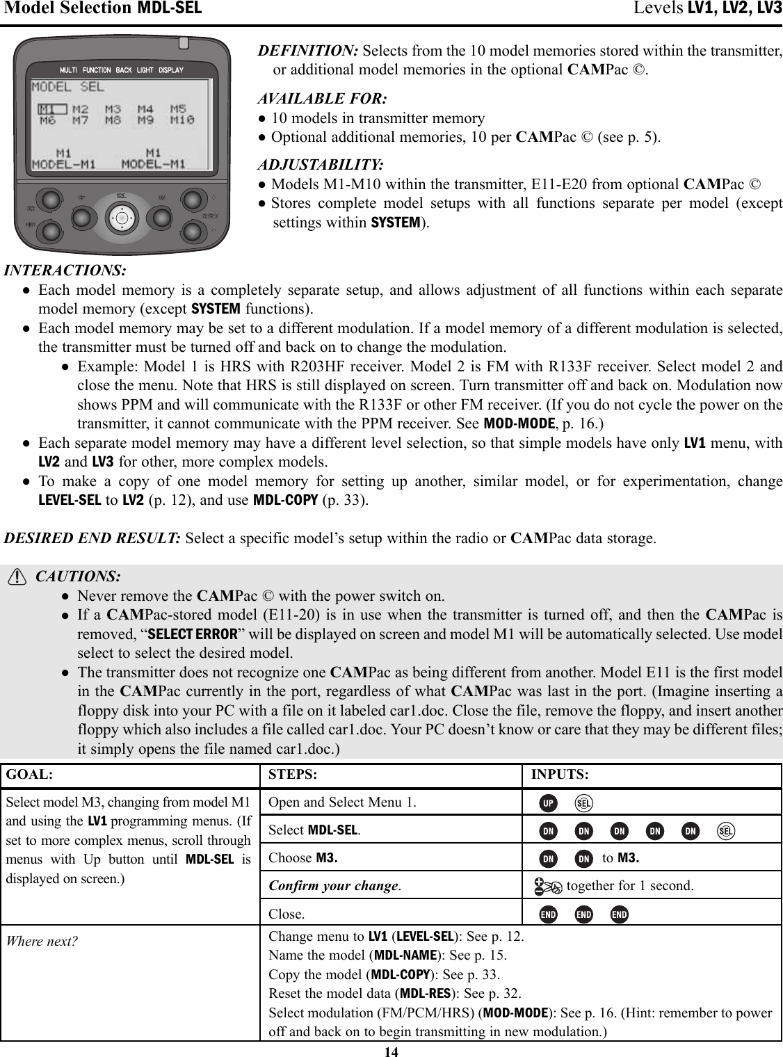
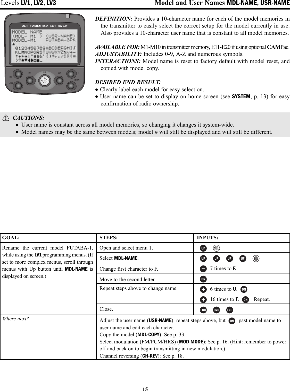
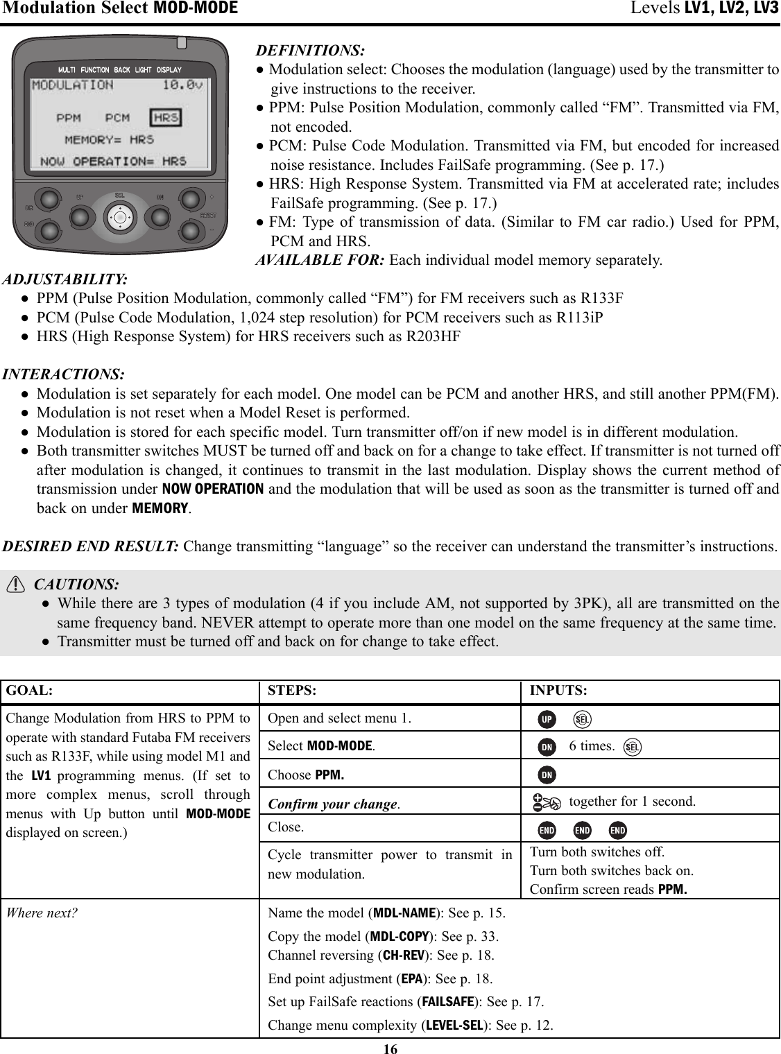
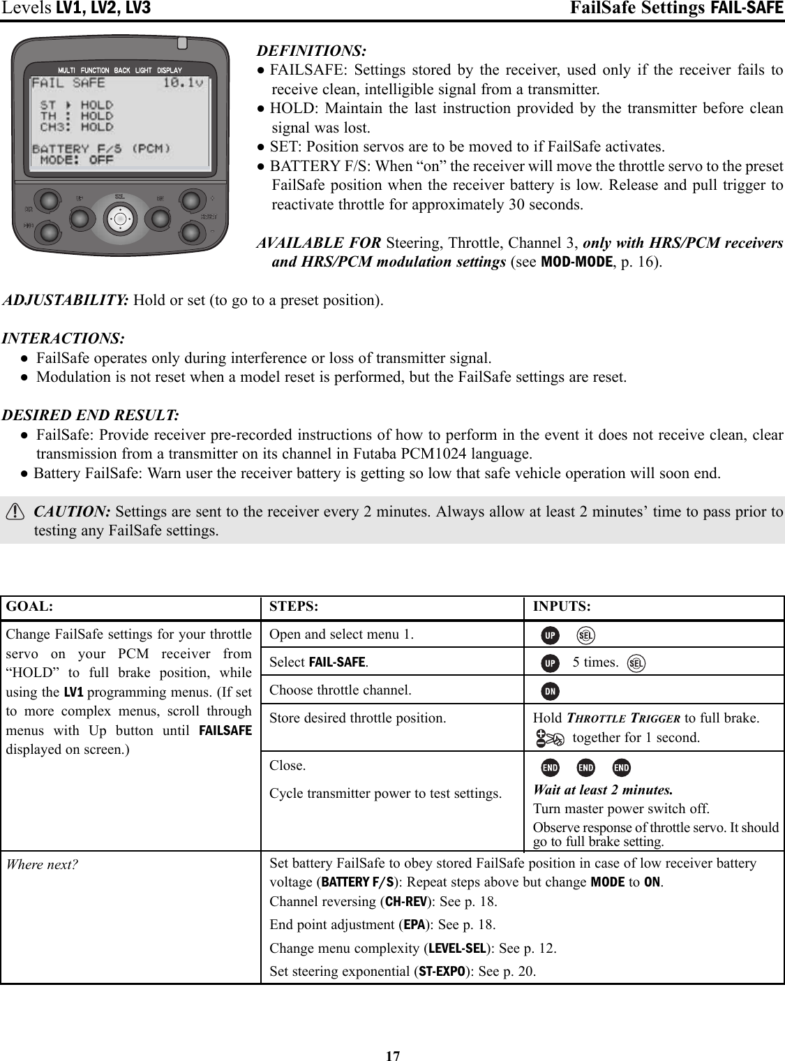
1.
User Manual Part 1
2.
User Manual Part 2
3.
User Manual Part 3
User Manual Part 1
Navigation menu
Upload a User Manual
Namespaces
Wiki Guide
HTML
PDF
Info
Views
User Manual
Discussion / Help
Navigation
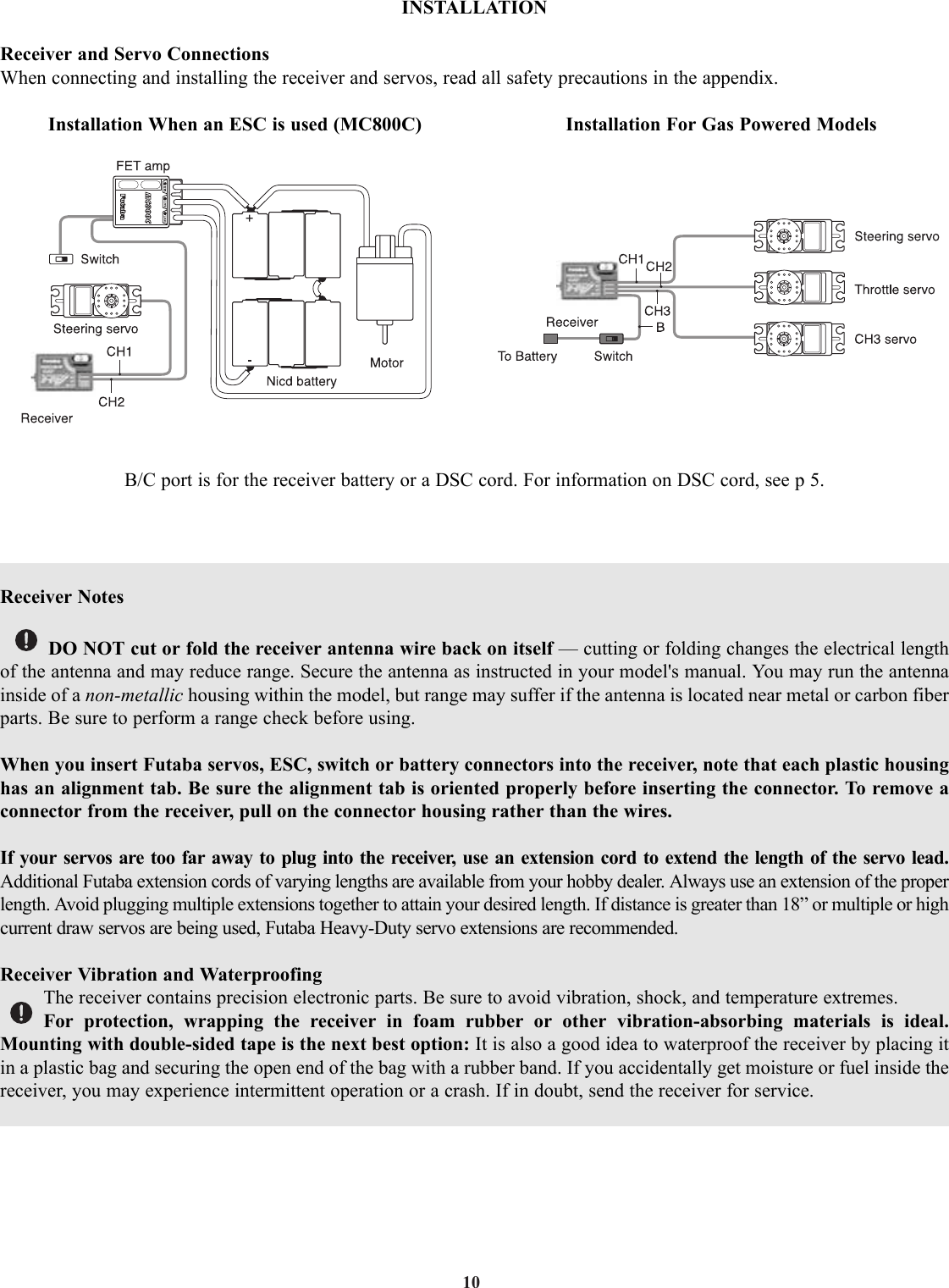
![5•Transmitter, including RF module* (PK) and NiCdbattery pack NT8F700B or battery holder• Receiver (R113iP or R203HF)• Wall charger (NiCd system only)• Frequency Flag• Wheel position offset adapter (APA)Transmitter T3PK (Pistol, 3 channels)Operating system: FM/PCM1024/HRSTransmitting frequency: 27, 29, 40, 41, 75 MHz bands* Modulation: FM/PPM, HRS-FM or PCM1024, switchablePower supply: 9.6V NiCd battery or 12V alkaline batteryCurrent drain: 250 mA or lessReceiver R113iP ( PCM Single conversion, 3 channels)Receiving frequency: 27, 29, 40, 41, 75 MHz bands *‡Intermediate freq.: 455 kHzPower requirement: 4.8V or 6.0V NiCd battery or 6.0V (4 cells) alkaline batteryCurrent drain: 18 mASize: 1.69" x 1.13" x 0.63" [42.7 x 28.7 x 16.0mm]Weight: 0.74oz [21g]Receiver R203HF (3 channels, HRS single conversion)Receiving frequency: 27, 29, 40, 41, 75 MHz bands *‡Intermediate frequency: 455kHzPower requirement: 6.0V only (shared with servos)Current drain: 14mASize: 1" x 1-1/2" x 9/16" [25.6 x 37.7 x 14.3mm] Weight: .6oz [17g]Always use only: “HRS” mode on transmitter6V Digital Servo, including throttle6V NiCd battery* Transmitter band may only be changed by changing themodule. Receiver band cannot be changed. Band cannot bechanged by simply changing crystals.‡ Only 27, 75MHz bands are legal for R/C ground usein the North America.Other bands are sold and used in other countries only.CONTENTS AND TECHNICAL SPECIFICATIONS(Specifications and ratings are subject to change without notice.)Your system includes the following components:The following additional accessories are available from your dealer. Refer to a Futaba catalog for more information:•CAMPac Memory module — the optional DP-16K CAMPac increases your model storage capability (to 20 modelsfrom 10) and allows you to transfer programs to another 3PK transmitter. Note that data may not be transferred to/fromany other model of transmitter (3PJ, etc). CAUTION - Insertion of a CAMPac containing data of a different transmitter type (ex: 3PJ) will result ina complete CAMPac data reset and loss of all data.•Transmitter battery pack — the NT8F700B (700mAh) transmitter NiCd battery pack may be easily exchanged with afresh one to provide enough capacity for extended sessions.•Y-harnesses, servo extensions, etc – Genuine Futaba extensions and y-harnesses, including a Heavy-Duty version withheavier gauge wire, are available to aid in your larger model and other installations.•5-cell (6.0V) receiver battery packs. All Futaba equipment (except that which is specifically labeled otherwise) isdesigned to work with 4.8V (NiCd 4 cells) or 6.0V (NiCd 5 cells or alkaline 4 cells). Using a 6.0V pack increases thecurrent flow to the servos, which accelerates their rate of response and their torque. However, because of this fastercurrent draw, a 5-cell battery pack of the same mAh rating will last approximately ¾ the time of a 4-cell pack. CAUTION - NOTE that HRS receivers require 6.0 volts and will not operate with 4.8V 4-cell packs.•Gyros – a variety of genuine Futaba gyros are available for your specialized model needs. •FailSafe: the FS1 FailSafe may be used with standard PPM/FM receivers to return throttle to idle in case of a loss of signal,similar to the FailSafe function of PCM/HRS receivers. NOTE that HRS receivers can not operate with the FS1.•Battery Holder (Transmitter): This battery holder is necessary when using the transmitter with dry cell batteries. For adescription of how to install the battery holder to the transmitter, see “NiCd Replacement” on page 54.•DSC cord – allows setup and testing without transmitting. Requires DSC compatible receiver and DSC cord. With transmitterand receiver off, plug cord into transmitter and then into receiver battery slot. Turn on receiver power. All programming andsetup may be done in this matter without transmitting. See glossary for a list of DSC-compatible receivers.Servo S9350 (High torque, Output torque: 10.0 kg-cmOperating speed: 0.12 sec/60digital servo)Size, Weight: 40 x 20 x 36.6 mm, 61 gServo S9350 (w/servo system only)](https://usermanual.wiki/Futaba/PK-AM-75.User-Manual-Part-1/User-Guide-382383-Page-5.png)