Futaba PK-AM-75 Radio Control Transmitter User Manual Part 2
Futaba Corporation Radio Control Transmitter Part 2
UserManual.wiki
>
Futaba
>
PK-AM-75 User Manual
>
User Manual Part 2
Contents
1.
User Manual Part 1
2.
User Manual Part 2
3.
User Manual Part 3
User Manual Part 2
Navigation menu
Upload a User Manual
Namespaces
Wiki Guide
HTML
PDF
Info
Views
User Manual
Discussion / Help
Navigation
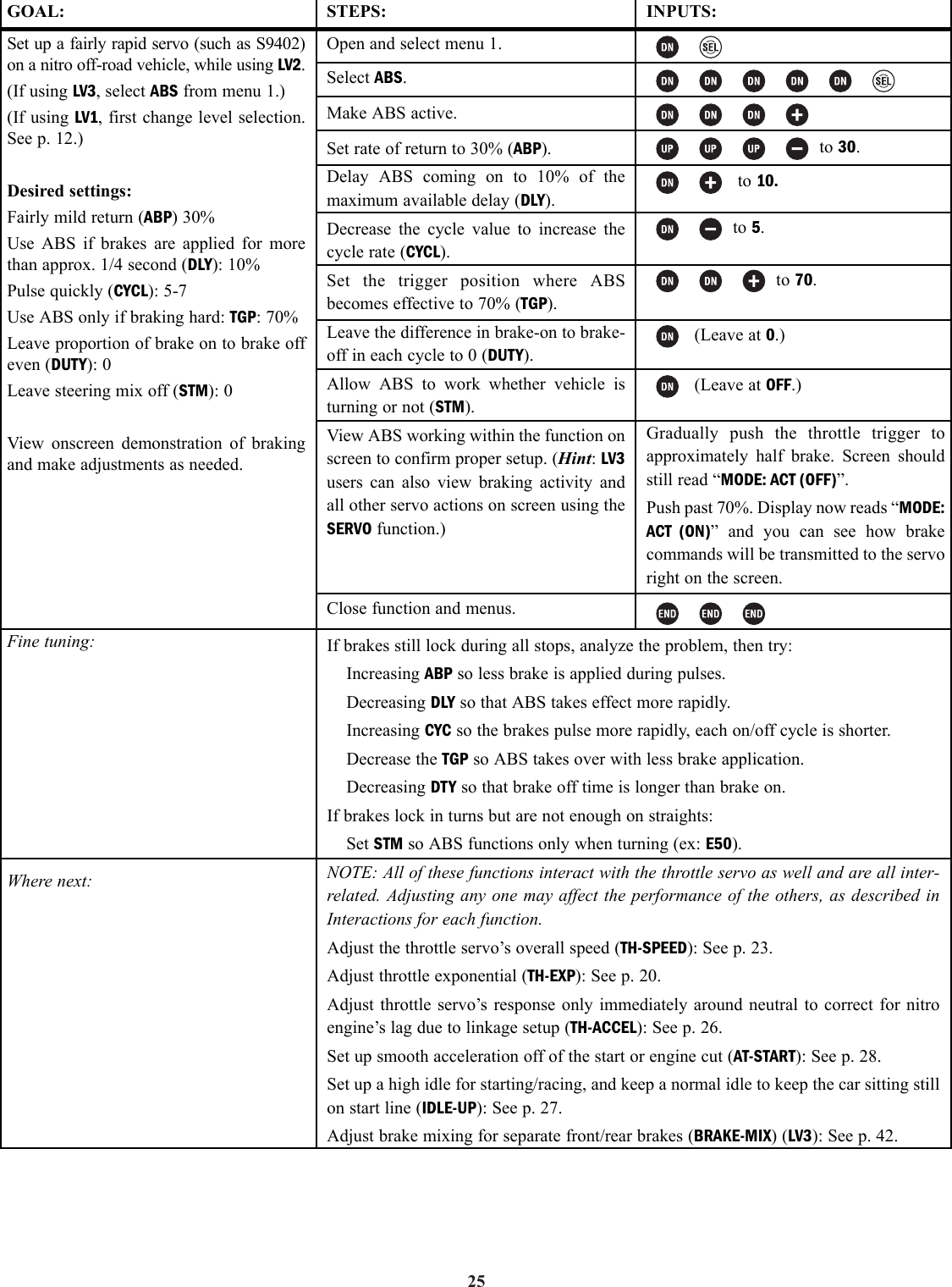
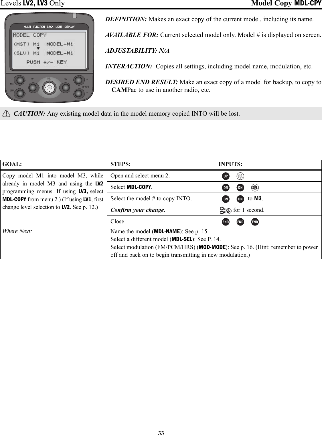
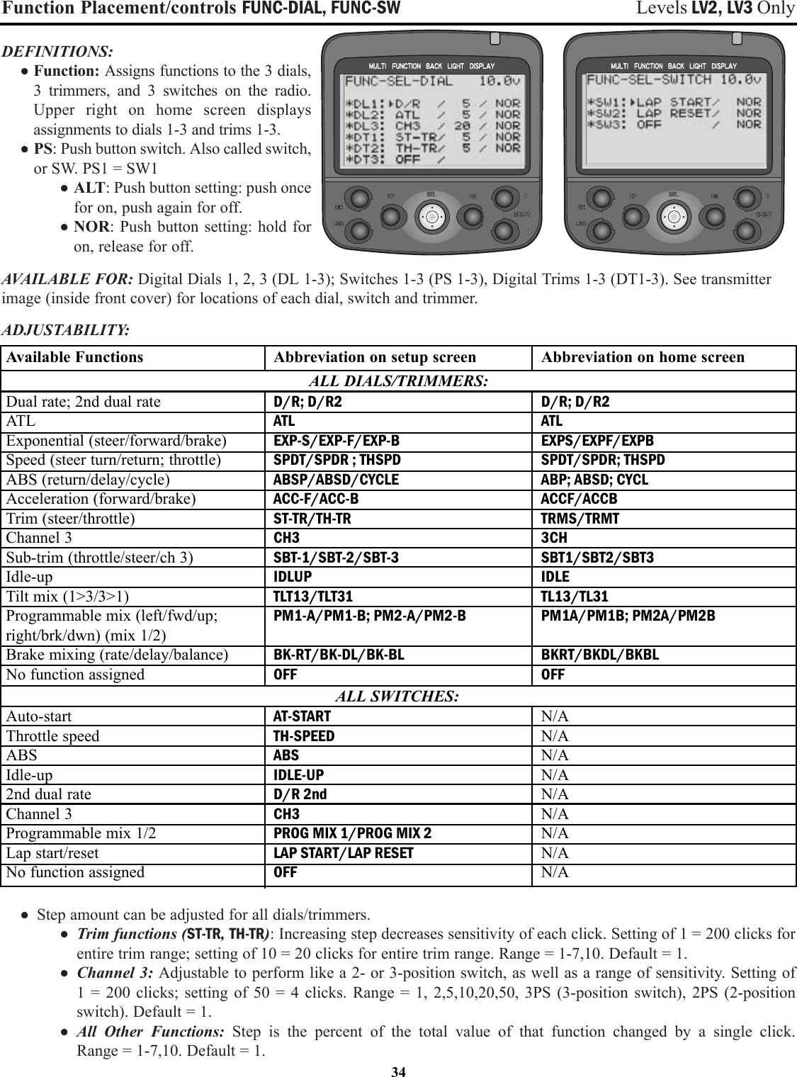
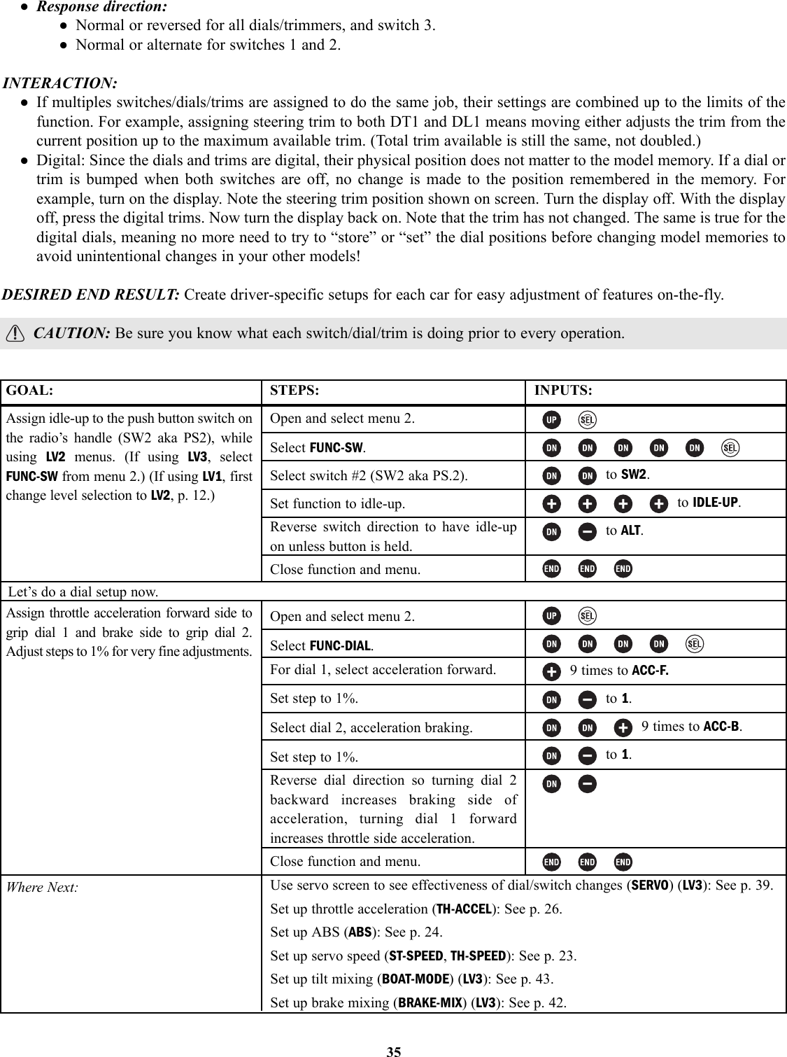
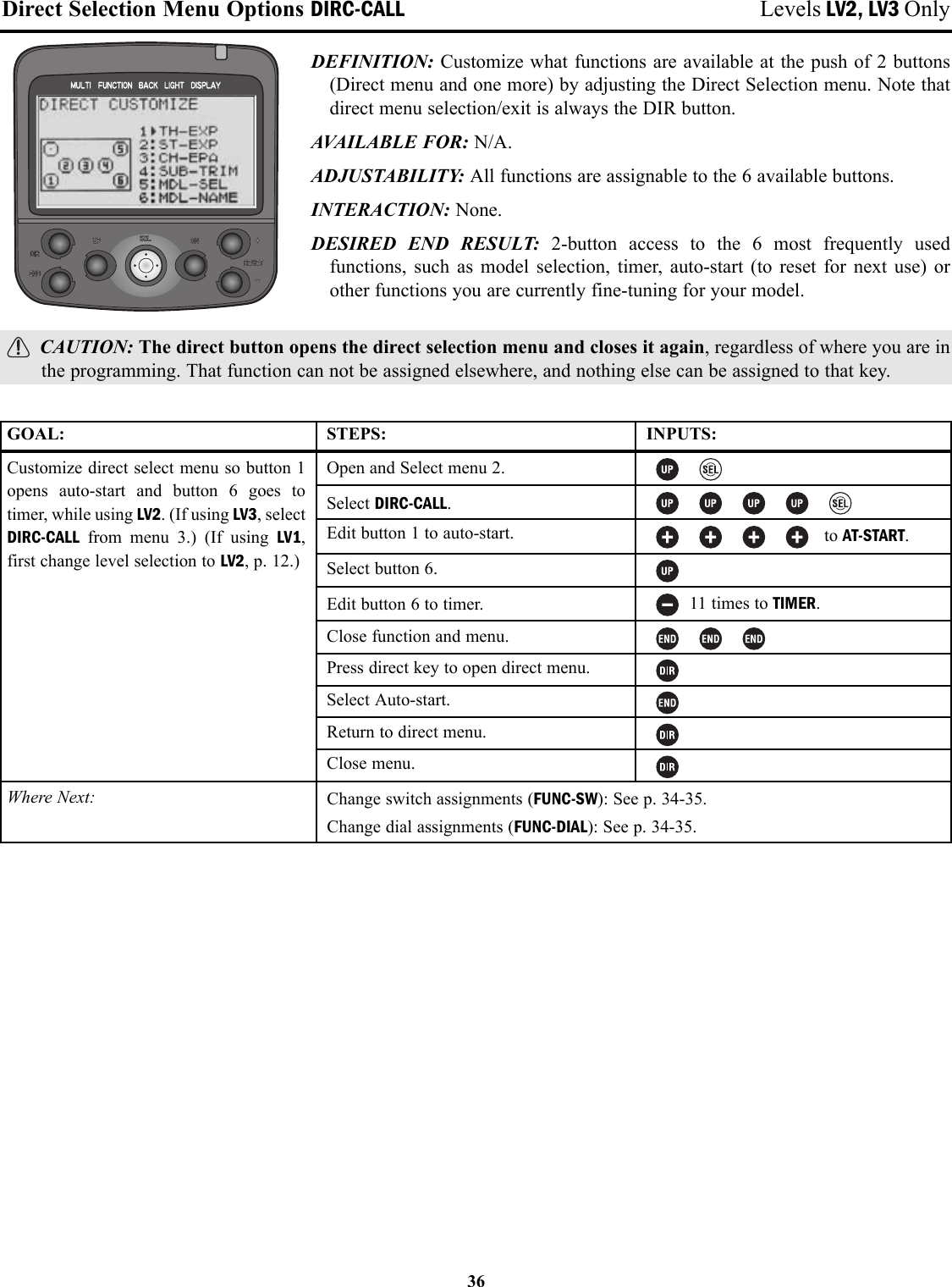
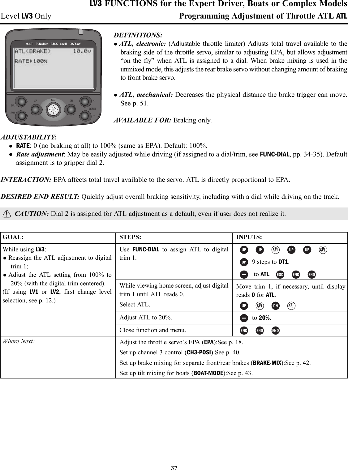
![Anti-Lock Braking ABS Levels LV2, LV3 OnlyDEFINITIONS: • ABS: Simulates a full size car’s antilock braking by pulsing the brake on and off rapidly.• ABP: Amount of brake return, how far the braking response is decreasedduring the pulses.• DLY: Delay; determines how long the braking is applied before ABS begins to operate.• CYC: Cycle speed adjustment, sets how rapidly the brakes cycle from fullbrake to ABP and back.• TGP: Trigger point, sets at what point ABS will be activated. ABS does notrespond if less brake is provided than the trigger point setting.• DTY: Cycle duty ratio, sets the proportion of the total cycle spent with brakesapplied full vs. ABP.• STM: Steering mix setup, controls when the ABS is triggered based upon amount of steering input. Designed todecrease skidding when vehicle is in a turn, and minimize spin outs.AVAILABLE FOR: Braking only.ADJUSTABILITY: • ABP: 0 (no ABS) to 100% [Servo goes to neutral (no brake) during pulse].• DLY: 0 (ABS responds immediately) to 100% (1.7 seconds of full brake before ABS takes over).• CYC: 1 (fastest) to 30 (slowest). Default=10.• TGP: 10-100.• DTY: -3 (longest full brake application — most likely to skid) to + 3 (shortest full brake – least likely to skid).• STM: OFF, N10-N100, E10-E100.• MODE:Inhibited, Active but switch is off, Active and switch is on.• Switch assignment can be changed in FUNC-SW (see pp. 34-35).• Each ABS variable can be assigned to dials in FUNC-DIAL (pp. 34-35) for on-the-course adjustability.INTERACTIONS:• EPA, servo reversing, dual rates, Speed Limiter, acceleration, auto-start, and exponential all interact to create theoverall braking effect.• Brake mixing works with ABS as if only one brake servo were used. No second setup for ABS is required.• Trigger point, steering mix and assigned switch each control ABS. All three must “say OK” for ABS to respond.DESIRED END RESULT: Model stops as rapidly as possible without skidding.CAUTIONS:• Careful analysis of the problem causing skids is required to adjust the proper portion of ABS for best results.• Adjustments to EPA, auto-start, expo, speed, brake mixing, vehicle’s suspension, tire compounds, enginetuning and ATL will all affect the performance of the ABS settings.24](https://usermanual.wiki/Futaba/PK-AM-75.User-Manual-Part-2/User-Guide-382384-Page-4.png)