Futaba PK-AM-75 Radio Control Transmitter User Manual Part 2
Futaba Corporation Radio Control Transmitter Part 2
Futaba >
Contents
- 1. User Manual Part 1
- 2. User Manual Part 2
- 3. User Manual Part 3
User Manual Part 2
AVAILABLE FOR: Steering (ST-EXP), Throttle (TH-EXP)
ADJUSTABILITY:
• Range: -100% to +100%
• Throttle: Forward and Braking
• Steering: Left and right
• Types: (TH-EXP forward only) Variable trace, curve, or exponential curves.
• May be assigned to a dial for on-the-track adjustability. (See FUNC-DIAL, pp. 34-35.)
INTERACTIONS:
• Exponential affects the servo’s response around center, and affects all built-in and programmable mixing functions
such as throttle acceleration, brake mixing, ABS, etc. All mixing functions respond based upon the position the
transmitter is telling the servo to go to, not the amount of trigger being pulled or wheel turned.
• EPA affects the total travel of the servo, and exponential is proportional to and affected by that total travel.
• AT-START, TH-SPEED, TH-ACCEL and other features interact with this function. For example, a very high VTR rate will
result in rapid acceleration early in the trigger movement. Therefore, the engine reaches wide open at, for example,
half throttle trigger. This may make it seem as though Speed Limiter programming is needed when you really should
adjust the VTR rate to create a more normal throttle response.
DESIRED END RESULT:
• Positive exponential makes the servo move farther for the same amount of input when around neutral (for sharper
steering when small inputs are given, for example).
• Negative exponential makes the servo move less for the same input when around neutral (to make a nitro engine’s response
to the throttle trigger smoother and more consistent between the first 1/4 of the trigger and the last 1/4 of the trigger.)
CAUTIONS:
• Too much positive exponential can make the model so overly sensitive it may be impossible to control.
• Too much negative exponential can make the model so non-responsive, your inputs may be too little too late,
resulting in a crash.
• Too high of a rate on a throttle VTR will result in the engine reaching full throttle well before the trigger is at full
throttle, which may result in wheel spin, especially upon acceleration.
21
GOAL:
Making the steering servo less responsive
around center to get rid of oversteering
when trying to make corrections at high
speeds, while using the LV1 programming
menus. (If set to more complex menus,
scroll through menus with Up button until
ST-EXP displayed on screen.)
Where next?
STEPS:
Open and select menu 1.
Select ST-EXP (TH-EXP for throttle.)
Add negative exponential until servo is in
desired position.
Close.
INPUTS:
to –25%.
Create a throttle VTR with a rate of 0 and a trigger point of 50%. See how it is just a
straight throttle response? Now hold the throttle at 1/2 trigger while adjusting the rate.
See how increasing or decreasing the VTR will then cause the throttle servo to open
sooner, or slower, on a smoothly linear response?
Adjust braking expo for softer response around neutral. Repeat steps above in TH-EXP.
Set FailSafe (FAIL-SAFE): See p. 17.
Change menu complexity to access additional features (LEVEL-SEL): See p. 12.
Set speed of response for steering/throttle (ST-SPEED, TH-SPEED): See p. 23.
Set acceleration rate to avoid wheel spin (AT-START): See p. 28.
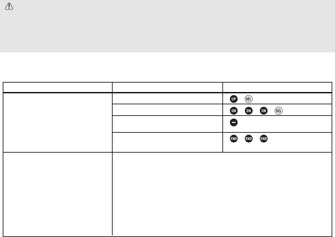
Sub-Trim SUBTRIM Levels LV1, LV2, LV3
DEFINITION: Fine tuning adjustment for the center point of each servo. Similar to
using electronic trims on the radio, but subtrim moves the entire servo’s travel
rather than just sliding the servo left/right within the total travel. The setting is
stored within the programming and the onscreen displays continue to show neutral.
AVAILABLE FOR: Steering, throttle, channel 3
ADJUSTABILITY:
•Steering: left 100 to right 100
•Throttle: brake 100 to throttle 100
•Channel 3: -100 to +100
•May be assigned to a dial/trim. (See FUNC-DIAL, pp. 34-35.)
INTERACTIONS:
• ALWAYS adjust your digital trims back to neutral prior to adjusting your subtrim. Then adjust the subtrim until the
servo is at the desired location without needing any digital trim.
• Subtrim adjusts the entire range of the servo to one side or the other; it does NOT adjust the servo’s center point
toward one end of the total travel like digital trims.
• Subtrim affects the neutral point for the servo for all other functions.
DESIRED END RESULT: Fine-tune the servo’s center point to correct for minor linkage problems.
CAUTION: The range of subtrim is limited. Always adjust linkages to get the servo’s center as close to the desired
location mechanically and only use trim functions as absolutely necessary.
22
GOAL:
Moving the steering servo arm one tooth
on the servo results in a slight right turn;
moving it back one causes a slight left
turn. Adjust the servo’s center (example:
5) so that the vehicle travels perfectly
straight with no steering input, while using
the LV1 programming menus. (If set to
more complex menus, scroll through
menus with Up button until SUB-TRIM
displayed on screen.)
Where next?
STEPS:
Open and select menu 1.
Select SUB-TRIM.
Cursor down to throttle and up to steering
to see the cursor positioning.
Add trim until servo is in desired position.
Close.
INPUTS:
to L5.
Set end point (EPA): See p. 18.
Set exponential (ST-EXP, TH-EXP): See p. 20.
Change menu complexity to access additional features (LEVEL-SEL): See p. 12.
Set idle-up (IDLE-UP): See p. 27.
Set throttle acceleration (TH-ACCEL): See p. 26.
LV2 FUNCTIONS for the Race-Ready Driver
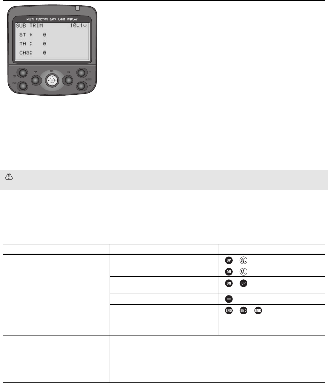
Levels LV2, LV3 Only Servo Maximum Speed Limiter (ST-SPEED,TH-SPEED)
DEFINITION: Speed Limiter decreases the maximum speed of the servo. This
may be adjusted individually for turning and returning the servo to neutral
(steering), and for high and low throttle settings.
A servo which responds too rapidly to a full-wheel input may cause the vehicle to
oversteer; to compensate many drivers steer too slowly, resulting in understeer
and not completing a clean corner. Others slow down to make the model more
controllable, losing valuable seconds. Speed Limiter helps in both these cases.
Similarly, applying throttle too suddenly results in wheel spin and wasted energy.
It may also cause a nitro engine to stall.
AVAILABLE FOR: Steering (ST-SPEED), Throttle (TH-SPEED)
ADJUSTABILITY:
• 1% (slowest possible response) to +100% (normal response)
• On input and return (ST-SPEED only); High speed and low speed (TH-SPEED only)
• On/off switch may be assigned for TH-SPEED only. Switch selection made in FUNC-SW (see pp. 34-35).
• Throttle speed and steering turn/return may each be assigned to a dial. See FUNC-DIAL (pp. 34-35).
INTERACTIONS/COMPARISONS:
• Increasing EPA decreases the rate at which a servo reaches a given point mechanically; therefore, adjusting EPA will
also adjust the actual rate of response of that servo.
• Negative exponential softens how far the servo responds to a given input vs. how fast. Either is used to settle a
“twitchy vehicle”, but the driver must first determine if the servo is moving too far, or simply too quickly.
• ABS pulsates the amount of brake given for a certain input to avoid overbraking and skidding the entire time brake
is applied. Speed Limiter slows the brake command and decreases skidding only when brakes are first applied.
• Throttle acceleration gives a significant sudden movement of the throttle servo only when the trigger is first moved;
Speed Limiter would slow that quick step off idle and diminish the effectiveness of acceleration. Thus, modifying
Speed Limiter may require adjustments to acceleration, and vice versa.
• Auto-start moves/holds the servo to a preset position when the throttle is applied the first time, then allows the servo
to operate through its normal travel for the rest of the run; Speed Limiter slows the performance of the throttle servo
at all times. If the problem is spinning on starts only, then auto-start should be adjusted, NOT Speed Limiter.
• Idle-up increases the throttle idle as if throttle trim were applied, and is used to make starting nitro engines easier.
Speed Limiter will only effect how rapidly the engine responds when additional throttle is applied.
• ATL adjusts the end point of the braking side only; Speed Limiter affects how quickly that total distance is traveled.
Adjustments to either may require fine adjustments to the other.
DESIRED END RESULTS:
• Servo reaches actual travel commanded by trigger/wheel position, just at a more gradual rate.
• Minimize wheel spin, harsh acceleration out of corners, understeering and spins.
23
GOAL:
Decrease throttle rate of response when
applying more than 40% throttle, to
minimize torque/spinning when accelerating
out of turns, while using the LV2
programming menus. (If set to LV3, select
TH-SPEED from menu 1). (If set to LV1, first
change level selection. See p. 12.)
Where next?
STEPS:
Open and select menu 1.
Select TH-SPEED. (use ST-SPEED to adjust
steering servo speed.)
Make active only above 40% trigger.
Decrease response speed to 50%.
Activate the function.
Close.
INPUTS:
to H40.
to 50%.
Assign on/off for throttle speed (FUNC-SW): See pp. 34-35.
Set ABS braking (ABS): See p. 24.
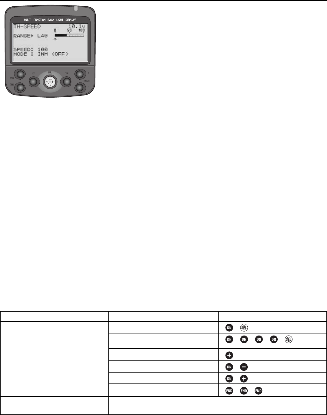
Anti-Lock Braking ABS Levels LV2, LV3 Only
DEFINITIONS:
• ABS: Simulates a full size car’s antilock braking by pulsing the brake on and
off rapidly.
• ABP: Amount of brake return, how far the braking response is decreased
during the pulses.
• DLY: Delay; determines how long the braking is applied before ABS begins
to operate.
• CYC: Cycle speed adjustment, sets how rapidly the brakes cycle from full
brake to ABP and back.
• TGP: Trigger point, sets at what point ABS will be activated. ABS does not
respond if less brake is provided than the trigger point setting.
• DTY: Cycle duty ratio, sets the proportion of the total cycle spent with brakes
applied full vs. ABP.
• STM: Steering mix setup, controls when the ABS is triggered based upon amount of steering input. Designed to
decrease skidding when vehicle is in a turn, and minimize spin outs.
AVAILABLE FOR: Braking only.
ADJUSTABILITY:
• ABP: 0 (no ABS) to 100% [Servo goes to neutral (no brake) during pulse].
• DLY: 0 (ABS responds immediately) to 100% (1.7 seconds of full brake before ABS takes over).
• CYC: 1 (fastest) to 30 (slowest). Default=10.
• TGP: 10-100.
• DTY: -3 (longest full brake application — most likely to skid) to + 3 (shortest full brake – least likely to skid).
• STM: OFF, N10-N100, E10-E100.
• MODE:Inhibited, Active but switch is off, Active and switch is on.
• Switch assignment can be changed in FUNC-SW (see pp. 34-35).
• Each ABS variable can be assigned to dials in FUNC-DIAL (pp. 34-35) for on-the-course adjustability.
INTERACTIONS:
• EPA, servo reversing, dual rates, Speed Limiter, acceleration, auto-start, and exponential all interact to create the
overall braking effect.
• Brake mixing works with ABS as if only one brake servo were used. No second setup for ABS is required.
• Trigger point, steering mix and assigned switch each control ABS. All three must “say OK” for ABS to respond.
DESIRED END RESULT: Model stops as rapidly as possible without skidding.
CAUTIONS:
• Careful analysis of the problem causing skids is required to adjust the proper portion of ABS for best results.
• Adjustments to EPA, auto-start, expo, speed, brake mixing, vehicle’s suspension, tire compounds, engine
tuning and ATL will all affect the performance of the ABS settings.
24
25
GOAL:
Set up a fairly rapid servo (such as S9402)
on a nitro off-road vehicle, while using LV2.
(If using LV3, select ABS from menu 1.)
(If using LV1, first change level selection.
See p. 12.)
Desired settings:
Fairly mild return (ABP) 30%
Use ABS if brakes are applied for more
than approx. 1/4 second (DLY): 10%
Pulse quickly (CYCL): 5-7
Use ABS only if braking hard: TGP: 70%
Leave proportion of brake on to brake off
even (DUTY): 0
Leave steering mix off (STM): 0
View onscreen demonstration of braking
and make adjustments as needed.
Fine tuning:
Where next:
STEPS:
Open and select menu 1.
Select ABS.
Make ABS active.
Set rate of return to 30% (ABP).
Delay ABS coming on to 10% of the
maximum available delay (DLY).
Decrease the cycle value to increase the
cycle rate (CYCL).
Set the trigger position where ABS
becomes effective to 70% (TGP).
Leave the difference in brake-on to brake-
off in each cycle to 0 (DUTY).
Allow ABS to work whether vehicle is
turning or not (STM).
View ABS working within the function on
screen to confirm proper setup. (Hint: LV3
users can also view braking activity and
all other servo actions on screen using the
SERVO function.)
Close function and menus.
INPUTS:
to 30.
to 10.
to 5.
to 70.
(Leave at 0.)
(Leave at OFF.)
Gradually push the throttle trigger to
approximately half brake. Screen should
still read “MODE: ACT (OFF)”.
Push past 70%. Display now reads “MODE:
ACT (ON)” and you can see how brake
commands will be transmitted to the servo
right on the screen.
If brakes still lock during all stops, analyze the problem, then try:
Increasing ABP so less brake is applied during pulses.
Decreasing DLY so that ABS takes effect more rapidly.
Increasing CYC so the brakes pulse more rapidly, each on/off cycle is shorter.
Decrease the TGP so ABS takes over with less brake application.
Decreasing DTY so that brake off time is longer than brake on.
If brakes lock in turns but are not enough on straights:
Set STM so ABS functions only when turning (ex: E50).
NOTE: All of these functions interact with the throttle servo as well and are all inter-
related. Adjusting any one may affect the performance of the others, as described in
Interactions for each function.
Adjust the throttle servo’s overall speed (TH-SPEED): See p. 23.
Adjust throttle exponential (TH-EXP): See p. 20.
Adjust throttle servo’s response only immediately around neutral to correct for nitro
engine’s lag due to linkage setup (TH-ACCEL): See p. 26.
Set up smooth acceleration off of the start or engine cut (AT-START): See p. 28.
Set up a high idle for starting/racing, and keep a normal idle to keep the car sitting still
on start line (IDLE-UP): See p. 27.
Adjust brake mixing for separate front/rear brakes (BRAKE-MIX) (LV3): See p. 42.
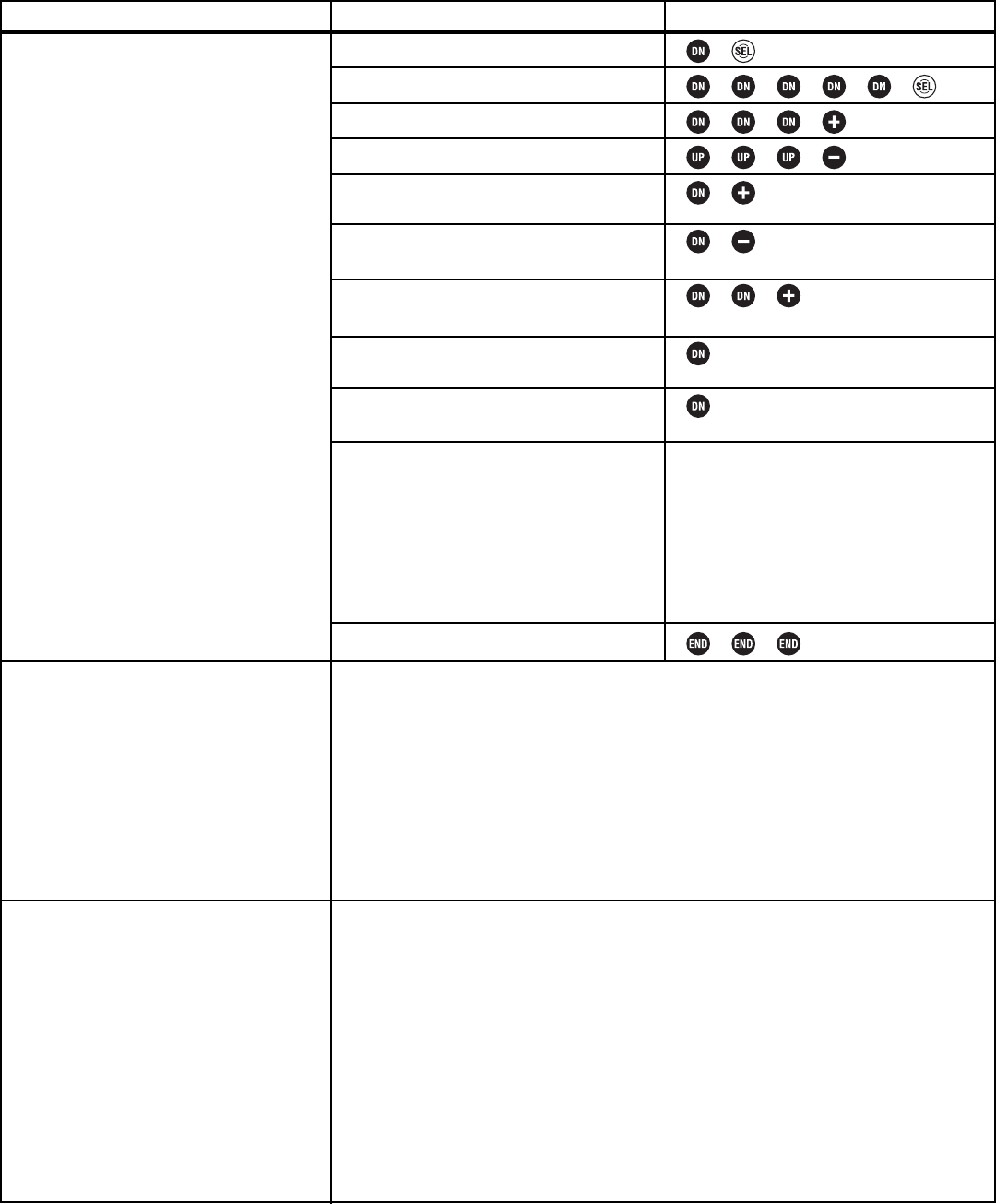
Rapid Throttle Acceleration THR-ACCEL Levels LV2, LV3 Only
DEFINITION: Due to the shape of some nitro engine linkages, throttle servo
movement near neutral results in very little movement of the pushrod. Throttle
acceleration simply jumps the servo from neutral to a portion of the total
available throw whenever the trigger is moved away from center. It does NOT
change the speed of the servo; the servo will jump to the input position at its
maximum possible speed. Unlike exponential, which adjusts the whole throttle
movement into a curve, throttle acceleration simply “jumps” away from neutral
and then leaves the remaining response linear. Accelerate is a pre-programmed
VTR throttle exponential (see p. 20).
AVAILABLE FOR: Throttle and braking separately.
ADJUSTABILITY: 0-100%.
• At 100% the throttle servo moves immediately to
approximately 40% of the total EPA.
• At 100% the brake servo moves immediately to full brake.
• Each setting may be assigned to a dial or trim for on-the-
track adjustability. (See FUNC-DIAL, pp. 34-35.)
INTERACTIONS:
• EPA will affect how far the servo moves in the jump. Changes in EPA may require adjusting throttle acceleration.
• Brake mixing works with acceleration as if only one brake servo were used. No second setup is required.
DESIRED END RESULT: Model responds to throttle/brake immediately, similar to an electric car.
CAUTION: High brake settings will result in locked brakes. Adjust throttle acceleration only enough to pick up the
slack in the linkage; then, utilize ABS to fine tune braking performance.
26
GOAL:
Remove throttle and braking “lag” due to
linkage in a 4WD nitro powered car, while
using LV2. (If using LV3, select TH-ACCEL
from Menu 1.) (If using LV1, first change
the level selection. See p. 12.)
Where next:
STEPS:
Open and select menu 1.
Select TH-ACCEL.
With receiver on, adjust forward until the
linkage opens the carb with the slightest
throttle input.
With receiver on, adjust brake until the
linkage applies brake with the slightest
brake input.
Close function and menu.
INPUTS:
6 times
as needed.
as needed.
NOTE: All of these functions interact with the throttle servo as well and are all inter-
related. Adjusting any one will affect the performance of the others.
Adjust the throttle servo’s overall speed (TH-SPEED): See p. 23.
Adjust throttle exponential (TH-EXP): See p. 20.
Setup ABS braking (ABS): See p. 24.
Set up smooth acceleration off of the start or engine cut (AT-START): See p. 28.
Set up a high idle for starting/racing, and keep a normal idle to keep the car sitting still
on start line (IDLE-UP): See p. 27.
Adjust brake mixing for separate front/rear brakes (BRAKE-MIX) (LV3): See p. 42.
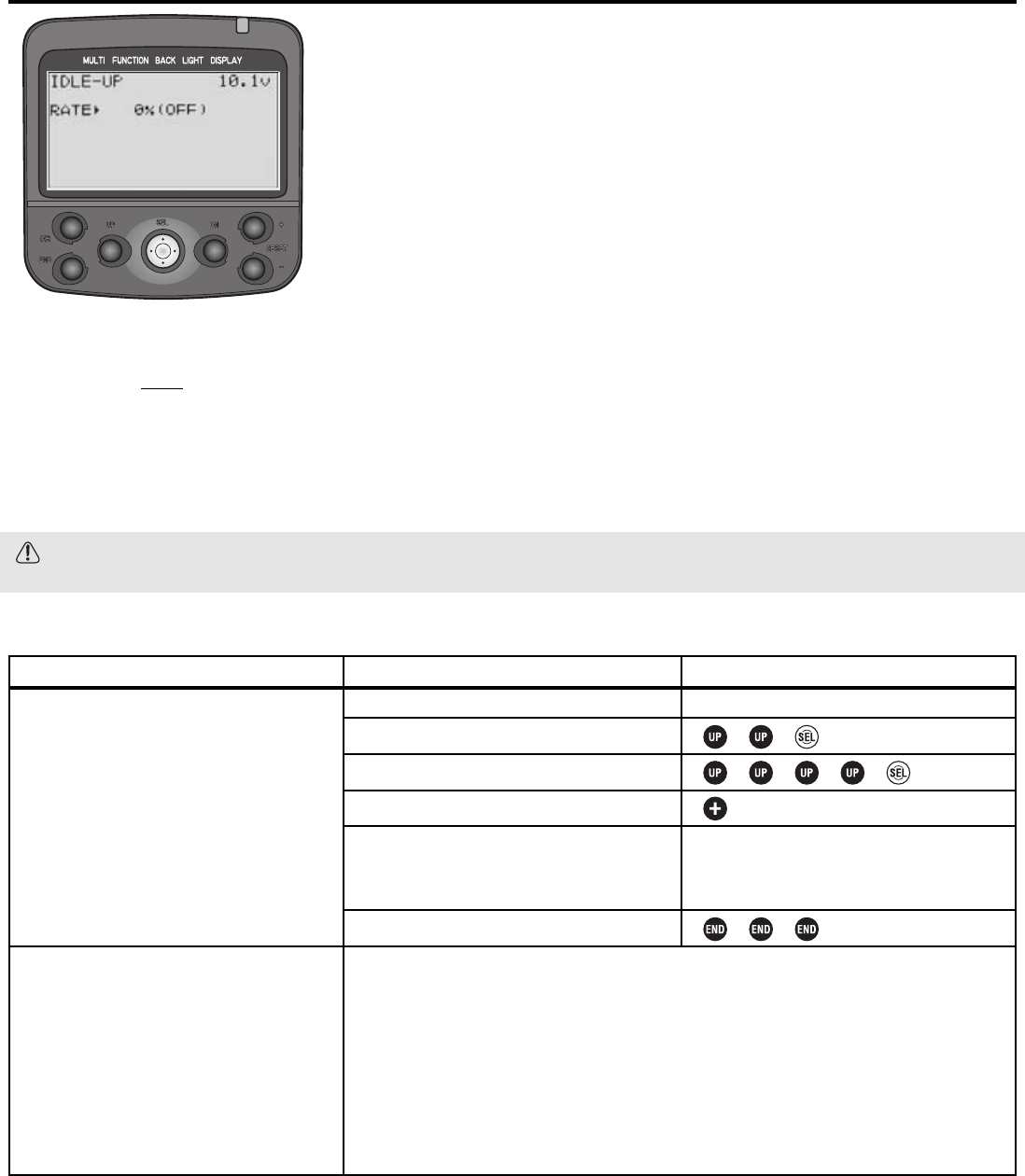
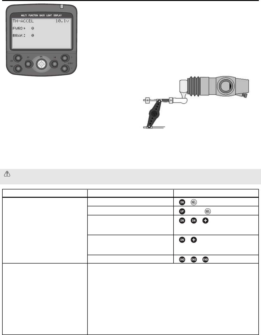
Levels LV2, LV3 Only Idle-Up IDLE-UP
DEFINITION: Adjusts the throttle’s idle/neutral point, usually used to create a
raised idle, making it easier to start the engine. May adjust either toward higher
idle (U) or toward braking (D).
AVAILABLE FOR: Throttle only.
ADJUSTABILITY:
•D50-1, 0, U1-50%. D = brake side. U = throttle side.
•Rate may be assigned to a dial or trim for on-the-track adjustability (see FUNC-
DIAL, pp. 34-35).
INTERACTION:
• Requires switch assignment in the FUNC-SW screen (see pp. 34-35).
• EPA does NOT affect the preset position of idle-up.
• Idle-up could actually exceed your total EPA. Idle-up obeys only the actual total servo travel and servo reversing, and
no other programmed changes.
DESIRED END RESULT: Throttle servo moves to a preset position when button is pushed and throttle trigger is at
idle. Has no effect at other throttle positions.
CAUTION: If you have to adjust your EPAs after setting up this function, be sure to double check that the pre-set
travel is still what is desired.
27
GOAL:
Set a high idle of 25% of servo travel to get
engine to start easily even when warm
from racing, while using LV2 programming
(If LV3, select IDLE-UP from menu 1). (If
using LV1, first change the level selection
to LV2. See p. 12.)
Where Next:
STEPS:
Set desired switch (FUNC-SW).
Open and select menu 1.
Select IDLE-UP.
Set desired rate to up (increase) 50%.
Test function on screen.
Close function and menu.
INPUTS:
See FUNC-SW (pp. 34-35).
to U 50%.
Press selected switch (ex: PS-1).
Note screen now reads “ON” and LED
blinks. Release switch.
NOTE: All of these functions interact with the throttle servo as well and are all inter-
related. Adjusting any one will affect the performance of the others.
Adjust throttle EPA (EPA): See p. 18.
Adjust the throttle servo’s overall speed (TH-SPEED): See p. 23.
Adjust throttle exponential (TH-EXP): See p. 20.
Setup ABS braking (ABS): See p. 24.
Set up smooth acceleration off of the start or engine cut (AT-START): See p. 28.
Adjust brake mixing for separate front/rear brakes (BRAKE-MIX) (LV3): See p. 42.
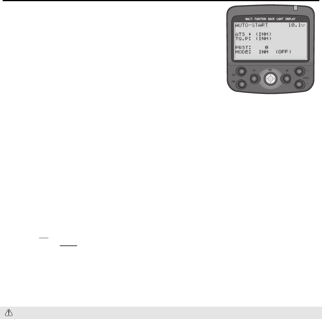
Auto-start Throttle Settings and Engine Cut AT-START Levels LV2, LV3 Only
DEFINITIONS:
• Auto-start: A pre-set throttle position, less than full throttle, to be used for the
initial acceleration off the line without having wheel spin. When the trigger is
released, auto-start is turned off and throttle operates normally again.
• ATS: Auto-start status.
• Engine Cut: Shuts the engine off without having to adjust the throttle trim. Takes
the throttle servo to a preset position when the switch is pressed. (Not available
to models using braking/reverse from the throttle servo. Primarily for boats.)
• TG.P: Trigger point at which auto-start is activated.
• PRST: Preset throttle servo position when function is activated. Preset is a
“true” preset – it is not a mix or a portion of the EPA. It is truly a
command to move the servo to a set position regardless of other inputs,
including trigger.
• MODE: Which function is being utilized at this time. (Engine cut and auto-start can not be used together).
• AT&SW: Auto-start is activated by throttle trigger or switch. Switch can be assigned in FUNC-SW (pp. 34-35) and
used to turn on/off the auto-start feature without having to pull or release the throttle trigger to do so.
• INH: Inhibited. Function is electronically inhibited and will not operate until changed to another setting.
• SW: Switch operated. Auto-start is inhibited and engine cut is available. (Assigned in FUNC-SW, pp. 34-35.)
AVAILABLE FOR: Throttle servo only.
ADJUSTABILITY:
• MMOODDEE:Inhibited, switch only (engine cut), auto-start with switch override (autostart).
• AATTSS: Inhibited, off (not available until set), ready (will activate on next trigger pull), active (operating now).
• TTGGPP: Inhibited, 5-95. Default: 5.
• PPRRSSTT: Brake 100-1, 0, Forward 0-100. Default: 0.
• Auto-start may be assigned to a switch. Engine cut must be assigned to a switch to operate. (See FUNC-SW, pp. 34-35.)
INTERACTIONS:
• EPA has NO effect on the preset position. The preset position may exceed EPA. Be sure to set auto-start after setting EPA.
• Servo reversing DOES change the direction of the preset in this function.
• No other function affects the preset except servo reversing.
• Trigger position has no effect on engine cut. Engine cut will shut engine to the preset position regardless.
• Auto-start must be restarted for each use by going to the auto-start function and pressing the + and – keys together
for one second while ATS is selected, or assigning and holding on a switch. (See FUNC-SW, p. 34-35.)
• If throttle triggered, auto-start remains active once started until the throttle trigger is returned to neutral.
DESIRED END RESULT: Avoiding wheel spin on starts and shutting engine off safely.
CAUTION: Remember that preset is not relative to EPA, so always check for binding if other changes have been made.
28
29
GOAL:
Set auto-start to avoid wheel spin, while
using LV2. (If using LV3, select AT-START
from menu 1.) (If using LV1, first change
the level selection, see p. 12.)
Example: Trigger point of 95% so that any
acceleration other than wide open off the line
will not trigger the auto-start feature.
Preset of 54% (determined on the track
that this is the maximum acceleration you
can have off the line without spinning.)
Where Next:
STEPS:
Open and Select Menu 1.
Select AT-START.
Select Auto-start mode.
Set pre-set position for throttle to go to
when auto-start is in use.
Set trigger point to activate auto-start.
Activate auto-start to be used on next full
acceleration.
Test function on screen.
Set desired end point (example 98%).
Close function and menu.
INPUTS:
to AT&SW.
to F54.
to 95.
to READY.
Pull trigger slowly until past 95%.
* displays at TGP.
ATS indicates ACT, MODE indicates ON.
Release trigger. ATS returns to OFF.
Press to re-activate.
Set up engine cut: Set mode to SW, set preset. You must also set cut switch in FUNC-SW
(pp. 34-35.)
Assign a switch to AT-START using FUNC-SW (p. 28), then test auto-start using switch
instead of trigger.
Adjust the throttle’s total travel (EPA): See p. 18.
Adjust the brake’s available travel/trim (TH-ATL)(LV3): See p. 37.
Adjust the throttle servo’s overall speed (TH-SPEED): See p. 23.
Adjust throttle exponential (TH-EXP): See p. 20.
Set up ABS braking (ABS): See p. 24.
Set up a high idle for easier engines starts (IDLE-UP): See p. 27.
Adjust brake mixing for separate front/rear brakes (BRAKE-MIX) (LV3): See p. 42.
Expert Tip: If you set up a switch in FUNC-SW (see pp. 34-35) assigned to auto-start,
you can use that switch to turn on/off the Auto-start feature without having to go to the
95% throttle position.
Timers TIMER Levels LV2, LV3 Only
DEFINITIONS:
• Total Timer: System timer, does not
reset/change with model selection, or
when transmitter is turned off, storing
total use time until it is reset.
• Racing Timer: Model-specific timer; types:
• Up Timer: Regular stop watch timer.
Counts up from 0 until stopped.
Runs consecutively until reset with
model selection or lap reset.
• Down Timer: Count-down timer.
Counts negatively once desired time
is passed (below 0). Runs consecutively until reset with model selection or lap reset.
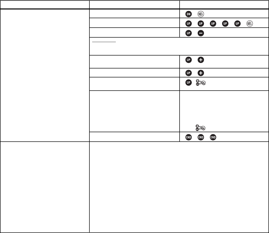
• Lap Memory Timer: Acts as a count-up timer, storing each lap and starting a new lap each time button is pressed,
while also maintaining a total run time count-up alarm, with a pre-alarm warning time. Stores up to 100 laps,
visible on LAP-LIST (see p. 31). Has a 3-second safety window where button press does not reset the lap.
• Lap Navigate Timer: Count-up timer which alarms at a set total run time, but also has a navigation alarm which
alarms every set interval (desired lap time), and then restarts the navigation alarm countdown on each button press
or upon passing each navigation alarm time. (Example: 4 minute track race, desired lap time is 30 seconds. Nav
alarm goes off if lap counter is not pressed before 30 seconds, then again after another 30 seconds, and so on until
4 minutes.) Great for practice-runs and working toward a target track time. Does NOT store individual lap times.
• LAP START: Switch assignment required to indicate start/stop, or the end of each lap in lap navigate and lap memory timers.
• LAP RESET:Switch assignment required to end timers and reset them to be used again.
• RUN: Timer is currently running, and displays total run timer, tracking total race time regardless of individual laps.
• STP: Timer is stopped.
• RST: Timer reset. Stops running timer, resets run timer, stores last lap to memory.
• RDY: Trigger-ready state. If set to ready, timer begins with trigger pull, doesn’t require lap start button to be pressed
to begin timer; however, lap button still needs to be pressed to store each lap. Trigger activity has no effect after
starting the timer.
• LAP: Current lap number.
• No.: Number of laps stored and ready to display.
• TIME: Current running lap time.
• NVALM: Number of times the navigation alarm went off, indicating you exceeded your target lap time.
• ALRM: Total run time prior to desired alarm.
• PRAL: Pre-alarm, warning that desired time is approaching, beeps once every second until alarm time is reached.
AVAILABLE FOR: N/A
ADJUSTABILITY:
• Timer types: See 5 timer types listed above (including total timer).
• System Time: 0 to 99 minutes 59 seconds. Resets to 0 at 100 minutes.
• Status: Reset (timer is reset, button will start), ready (throttle trigger or button starts), run, stop.
• Alarm: Off, 1-99 minutes. Default = 4 minutes.
• Pre-Alarm: Off, 1-30 seconds, warning that alarm is about to sound. Beeps every second. Default = 5 sec.
• Lap: Navigate timer only: 3 seconds to 30 minutes, interval counter to nav. alarm. Default = 3 seconds.
• Switches: Assign lap start/stop and reset buttons in FUNC-SW (see pp. 34-35).
INTERACTION:
• Requires switch assignment in the FUNC-SW screen. (See pp. 34-35.)
• Laps stored with a lap memory timer are visible using LAP-LIST. (See p. 31.)
DESIRED END RESULT: Provide user accurate time data for tracking laps, practicing, keeping track of fuel and battery
usage, etc.
CAUTION: Lap Memory has a 3-second safety. If button is re-pressed within 3 seconds, the timer is not reset a second time.
30
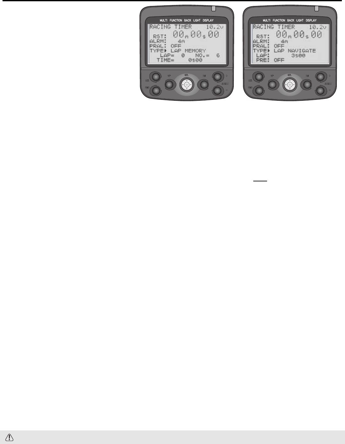
Levels LV2, LV3 Only Lap Listing LAP-LIST
DEFINITION: Displays all stored lap times, up to 100, and also stores total race
time, including run time after last but before reset/stop.
ADJUSTABILITY:
•Reset single lap: Select lap, cursor blinks next to it. Press together.
•Reset all laps in memory: Press and together for 1 second.
INTERACTION:
•Requires switch assignment for lap counter in the FUNC-SW screen (see pp. 34-35).
•Requires set up of timer as Lap Memory Timer (see p. 30).
•Lap Navigation Timer does NOT store lap times (see p. 30).
DESIRED END RESULT: Store multiple lap times to analyze performance after the race.
31
GOAL:
Set up a lap memory timer to track lap times
throughout a race, while using LV2 menus.
(If using LV3, select timer from Menu 1). (If
using LV1, first change level selection to
LV2. See p. 12.)
Where Next:
STEPS:
Assign desired lapstart and restart switches.
Open and select menu 1.
Select TIMER.
Set type to lap memory timer.
Set total race time to 5 minutes.
Set pre-alarm time to warn you race end is
nearing at 15 seconds.
Set total timer/first lap timer to trigger
when throttle is pulled.
Test function on screen.
Close function and menu.
INPUTS:
See FUNC-SW pp. 34-35.
to LAP MEMORY.
to ALRM. to 5m.
to 15s.
Screen reads RDY.
Pull trigger. Timer starts counting.
Press selected switch (ex: PS-1) to store
first lap.
Note screen now displays the first lap’s
time for 3 seconds, then displays current
running lap.
Press selected reset switch to stop timer.
System timer: Reset radio’s total timer after recharging to use as a method of tracking
on time between charges: from home screen, press and hold for one second.
View stored laps (LAP-LIST): See p. 31.
Adjust switch assignments (FUNC-SW): See pp. 34-35.
Place timer setup screen on quick menu for 2-keystroke access (DIRC-CALL): See p. 36.
GOAL:
View laps previously run, then reset all laps,
while using LV2. (If using LV3, select LAP-LIST
from menu 1.) (If using LV1, first change
level selection to LV2, p. 12.)
Where Next:
STEPS:
Open and Select Menu 1.
Select LAP-LIST.
Scroll through laps shown on screen.
Reset all laps to prepare for next practice.
Close function and menu.
INPUTS:
or as needed.
and together for 1 second.
Change timer type to lap navigate timer (laps will not be stored) (TIMER): See p. 30.
Adjust timer settings (TIMER): See p. 30.
Change switch assignment to start/stop lap timer (FUNC-SW): See pp. 34-35.
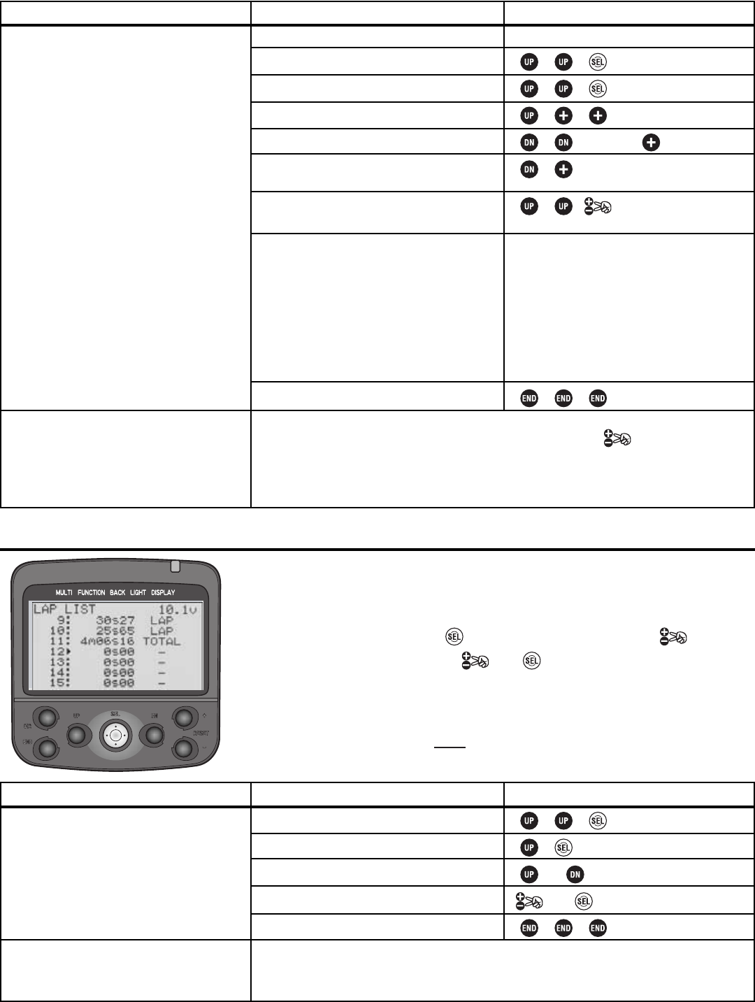
Model Reset MDL-RES Levels LV2, LV3 Only
DEFINITION: Erases all data stored in a specific model memory.
AVAILABLE FOR: Current selected model only. Model # is displayed on screen.
INTERACTIONS:
• Resets settings for the specific model memory currently in use without resetting any
settings for any other model in memory.
• Model reset does not reset:
• Modulation;
• System settings;
•Adjuster;
• Lap listings;
• User name;
• Direct selection menu setup.
• Model copy may be used prior to model reset to store a copy of this data, including to an optional CAMPac.
DESIRED END RESULT: Delete all existing programming from this model memory only.
CAUTIONS:
• Deleted data can not be restored.
• See list of functions NOT reset with a model reset under interactions.
32
GOAL:
Reset all data in Model #M3, while
already in model M3, and using the LV2
programming menus. (If using LV3, select
MDL-RES from menu 2.) (If using LV1, first
change level selection. See p. 12.)
Where Next?
STEPS:
Open and select menu 2.
Select MDL-RES.
Confirm your change.
If desired, return to LV1.
Close.
INPUTS:
for 1 second.
Name the model (MDL-NAME): See p. 15.
Copy the model (MDL-COPY): See p. 33.
Select a different model (MDL-SEL): See p. 14.
Select modulation (FM/PCM/HRS) (MOD-MODE): See p. 16. (Hint: remember to power
off and back on to begin transmitting in new modulation.)
Channel reversing (CH-REV): See p. 18.
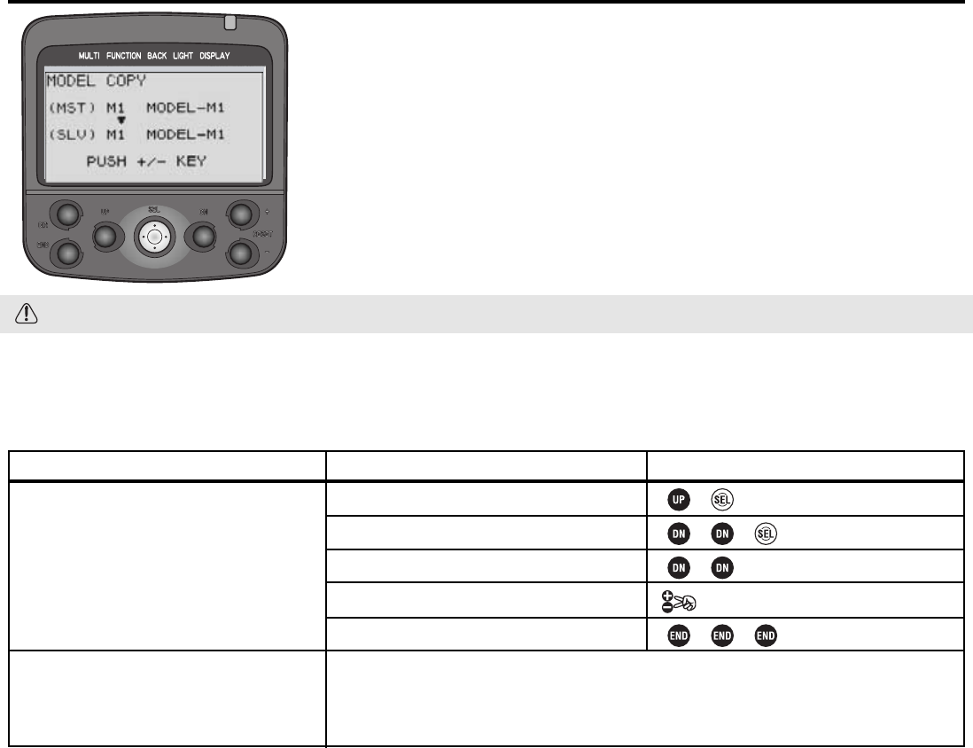
Levels LV2, LV3 Only Model Copy MDL-CPY
DEFINITION: Makes an exact copy of the current model, including its name.
AVAILABLE FOR: Current selected model only. Model # is displayed on screen.
ADJUSTABILITY: N/A
INTERACTION: Copies all settings, including model name, modulation, etc.
DESIRED END RESULT: Make an exact copy of a model for backup, to copy to
CAMPac to use in another radio, etc.
CAUTION: Any existing model data in the model memory copied INTO will be lost.
33
GOAL:
Copy model M1 into model M3, while
already in model M3 and using the LV2
programming menus. If using LV3, select
MDL-COPY from menu 2.) (If using LV1, first
change level selection to LV2. See p. 12.)
Where Next:
STEPS:
Open and select menu 2.
Select MDL-COPY.
Select the model # to copy INTO.
Confirm your change.
Close
INPUTS:
to M3.
for 1 second.
Name the model (MDL-NAME): See p. 15.
Select a different model (MDL-SEL): See P. 14.
Select modulation (FM/PCM/HRS) (MOD-MODE): See p. 16. (Hint: remember to power
off and back on to begin transmitting in new modulation.)
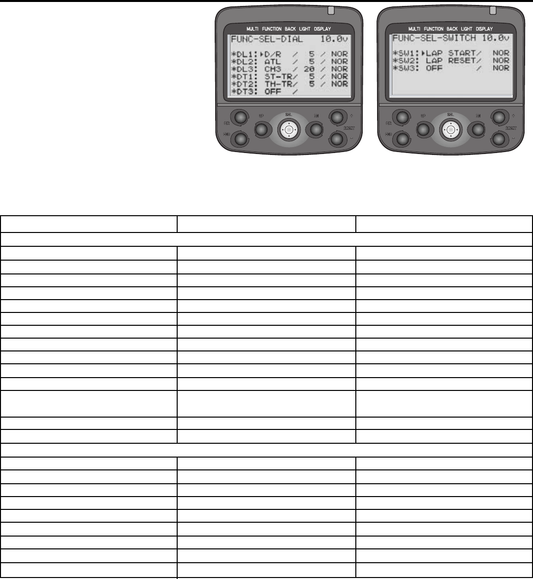
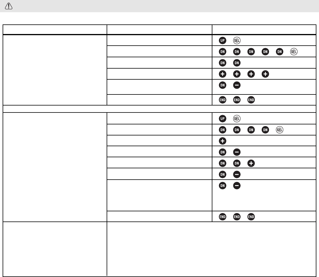
Function Placement/controls FUNC-DIAL, FUNC-SW Levels LV2, LV3 Only
DEFINITIONS:
•Function: Assigns functions to the 3 dials,
3 trimmers, and 3 switches on the radio.
Upper right on home screen displays
assignments to dials 1-3 and trims 1-3.
•PS: Push button switch. Also called switch,
or SW. PS1 = SW1
•ALT: Push button setting: push once
for on, push again for off.
•NOR: Push button setting: hold for
on, release for off.
AVAILABLE FOR: Digital Dials 1, 2, 3 (DL 1-3); Switches 1-3 (PS 1-3), Digital Trims 1-3 (DT1-3). See transmitter
image (inside front cover) for locations of each dial, switch and trimmer.
ADJUSTABILITY:
• Step amount can be adjusted for all dials/trimmers.
• Trim functions (ST-TR, TH-TR): Increasing step decreases sensitivity of each click. Setting of 1 = 200 clicks for
entire trim range; setting of 10 = 20 clicks for entire trim range. Range = 1-7,10. Default = 1.
• Channel 3: Adjustable to perform like a 2- or 3-position switch, as well as a range of sensitivity. Setting of
1 = 200 clicks; setting of 50 = 4 clicks. Range = 1, 2,5,10,20,50, 3PS (3-position switch), 2PS (2-position
switch). Default = 1.
• All Other Functions: Step is the percent of the total value of that function changed by a single click.
Range = 1-7,10. Default = 1.
34
Available Functions
Dual rate; 2nd dual rate
ATL
Exponential (steer/forward/brake)
Speed (steer turn/return; throttle)
ABS (return/delay/cycle)
Acceleration (forward/brake)
Trim (steer/throttle)
Channel 3
Sub-trim (throttle/steer/ch 3)
Idle-up
Tilt mix (1>3/3>1)
Programmable mix (left/fwd/up;
right/brk/dwn) (mix 1/2)
Brake mixing (rate/delay/balance)
No function assigned
Auto-start
Throttle speed
ABS
Idle-up
2nd dual rate
Channel 3
Programmable mix 1/2
Lap start/reset
No function assigned
Abbreviation on setup screen
D/R; D/R2
ATL
EXP-S/EXP-F/EXP-B
SPDT/SPDR ; THSPD
ABSP/ABSD/CYCLE
ACC-F/ACC-B
ST-TR/TH-TR
CH3
SBT-1/SBT-2/SBT-3
IDLUP
TLT13/TLT31
PM1-A/PM1-B; PM2-A/PM2-B
BK-RT/BK-DL/BK-BL
OFF
AT-START
TH-SPEED
ABS
IDLE-UP
D/R 2nd
CH3
PROG MIX 1/PROG MIX 2
LAP START/LAP RESET
OFF
Abbreviation on home screen
D/R; D/R2
ATL
EXPS/EXPF/EXPB
SPDT/SPDR; THSPD
ABP; ABSD; CYCL
ACCF/ACCB
TRMS/TRMT
3CH
SBT1/SBT2/SBT3
IDLE
TL13/TL31
PM1A/PM1B; PM2A/PM2B
BKRT/BKDL/BKBL
OFF
N/A
N/A
N/A
N/A
N/A
N/A
N/A
N/A
N/A
ALL DIALS/TRIMMERS:
ALL SWITCHES:
• Response direction:
• Normal or reversed for all dials/trimmers, and switch 3.
• Normal or alternate for switches 1 and 2.
INTERACTION:
• If multiples switches/dials/trims are assigned to do the same job, their settings are combined up to the limits of the
function. For example, assigning steering trim to both DT1 and DL1 means moving either adjusts the trim from the
current position up to the maximum available trim. (Total trim available is still the same, not doubled.)
• Digital: Since the dials and trims are digital, their physical position does not matter to the model memory. If a dial or
trim is bumped when both switches are off, no change is made to the position remembered in the memory. For
example, turn on the display. Note the steering trim position shown on screen. Turn the display off. With the display
off, press the digital trims. Now turn the display back on. Note that the trim has not changed. The same is true for the
digital dials, meaning no more need to try to “store” or “set” the dial positions before changing model memories to
avoid unintentional changes in your other models!
DESIRED END RESULT: Create driver-specific setups for each car for easy adjustment of features on-the-fly.
CAUTION: Be sure you know what each switch/dial/trim is doing prior to every operation.
35
GOAL:
Assign idle-up to the push button switch on
the radio’s handle (SW2 aka PS2), while
using LV2 menus. (If using LV3, select
FUNC-SW from menu 2.) (If using LV1, first
change level selection to LV2, p. 12.)
Assign throttle acceleration forward side to
grip dial 1 and brake side to grip dial 2.
Adjust steps to 1% for very fine adjustments.
Where Next:
STEPS:
Open and select menu 2.
Select FUNC-SW.
Select switch #2 (SW2 aka PS.2).
Set function to idle-up.
Reverse switch direction to have idle-up
on unless button is held.
Close function and menu.
Open and select menu 2.
Select FUNC-DIAL.
For dial 1, select acceleration forward.
Set step to 1%.
Select dial 2, acceleration braking.
Set step to 1%.
Reverse dial direction so turning dial 2
backward increases braking side of
acceleration, turning dial 1 forward
increases throttle side acceleration.
Close function and menu.
INPUTS:
to SW2.
to IDLE-UP.
to ALT.
9 times to ACC-F.
to 1.
9 times to ACC-B.
to 1.
Use servo screen to see effectiveness of dial/switch changes (SERVO) (LV3): See p. 39.
Set up throttle acceleration (TH-ACCEL): See p. 26.
Set up ABS (ABS): See p. 24.
Set up servo speed (ST-SPEED, TH-SPEED): See p. 23.
Set up tilt mixing (BOAT-MODE) (LV3): See p. 43.
Set up brake mixing (BRAKE-MIX) (LV3): See p. 42.
Let’s do a dial setup now.
36
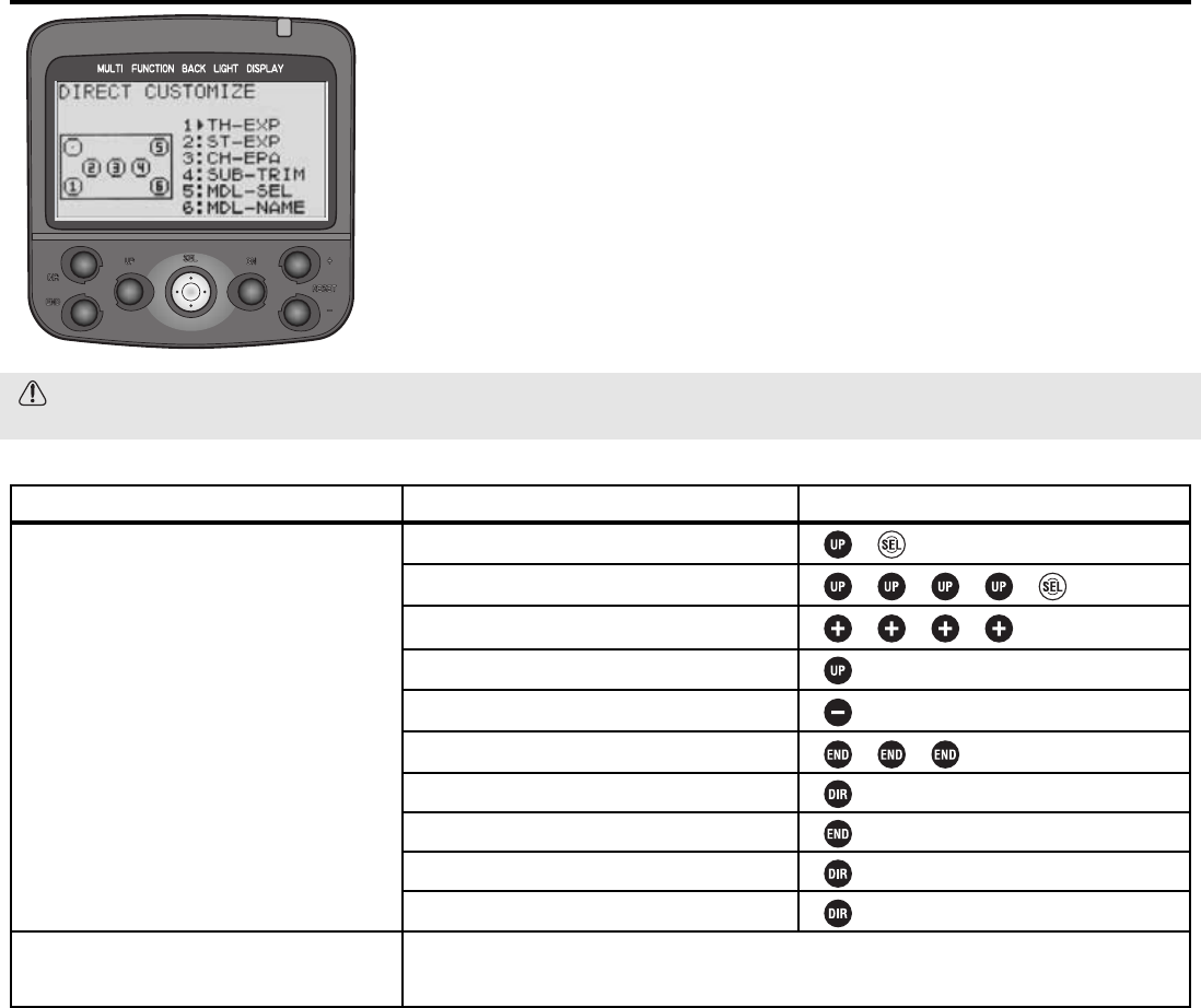
Direct Selection Menu Options DIRC-CALL Levels LV2, LV3 Only
DEFINITION: Customize what functions are available at the push of 2 buttons
(Direct menu and one more) by adjusting the Direct Selection menu. Note that
direct menu selection/exit is always the DIR button.
AVAILABLE FOR: N/A.
ADJUSTABILITY: All functions are assignable to the 6 available buttons.
INTERACTION: None.
DESIRED END RESULT: 2-button access to the 6 most frequently used
functions, such as model selection, timer, auto-start (to reset for next use) or
other functions you are currently fine-tuning for your model.
CAUTION: The direct button opens the direct selection menu and closes it again, regardless of where you are in
the programming. That function can not be assigned elsewhere, and nothing else can be assigned to that key.
GOAL:
Customize direct select menu so button 1
opens auto-start and button 6 goes to
timer, while using LV2. (If using LV3, select
DIRC-CALL from menu 3.) (If using LV1,
first change level selection to LV2, p. 12.)
Where Next:
STEPS:
Open and Select menu 2.
Select DIRC-CALL.
Edit button 1 to auto-start.
Select button 6.
Edit button 6 to timer.
Close function and menu.
Press direct key to open direct menu.
Select Auto-start.
Return to direct menu.
Close menu.
INPUTS:
to AT-START.
11 times to TIMER.
Change switch assignments (FUNC-SW): See p. 34-35.
Change dial assignments (FUNC-DIAL): See p. 34-35.
LV3 FUNCTIONS for the Expert Driver, Boats or Complex Models
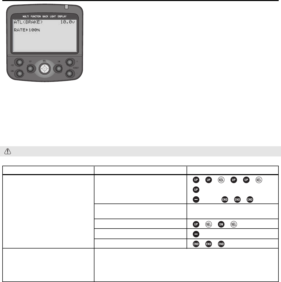
Level LV3 Only Programming Adjustment of Throttle ATL ATL
DEFINITIONS:
•ATL, electronic: (Adjustable throttle limiter) Adjusts total travel available to the
braking side of the throttle servo, similar to adjusting EPA, but allows adjustment
“on the fly” when ATL is assigned to a dial. When brake mixing is used in the
unmixed mode, this adjusts the rear brake servo without changing amount of braking
to front brake servo.
•ATL, mechanical: Decreases the physical distance the brake trigger can move.
See p. 51.
AVAILABLE FOR: Braking only.
ADJUSTABILITY:
• RATE: 0 (no braking at all) to 100% (same as EPA). Default: 100%.
• Rate adjustment: May be easily adjusted while driving (if assigned to a dial/trim, see FUNC-DIAL, pp. 34-35). Default
assignment is to gripper dial 2.
INTERACTION: EPA affects total travel available to the servo. ATL is directly proportional to EPA.
DESIRED END RESULT: Quickly adjust overall braking sensitivity, including with a dial while driving on the track.
CAUTION: Dial 2 is assigned for ATL adjustment as a default, even if user does not realize it.
37
GOAL:
While using LV3:
•Reassign the ATL adjustment to digital
trim 1;
•Adjust the ATL setting from 100% to
20% (with the digital trim centered).
(If using LV1 or LV2, first change level
selection, see p. 12.)
Where Next:
STEPS:
Use FUNC-DIAL to assign ATL to digital
trim 1.
While viewing home screen, adjust digital
trim 1 until ATL reads 0.
Select ATL.
Adjust ATL to 20%.
Close function and menu.
INPUTS:
9 steps to DT1.
to ATL.
Move trim 1, if necessary, until display
reads 0for ATL.
to 20%.
Adjust the throttle servo’s EPA (EPA):See p. 18.
Set up channel 3 control (CH3-POSI):See p. 40.
Set up brake mixing for separate front/rear brakes (BRAKE-MIX):See p. 42.
Set up tilt mixing for boats (BOAT-MODE):See p. 43.
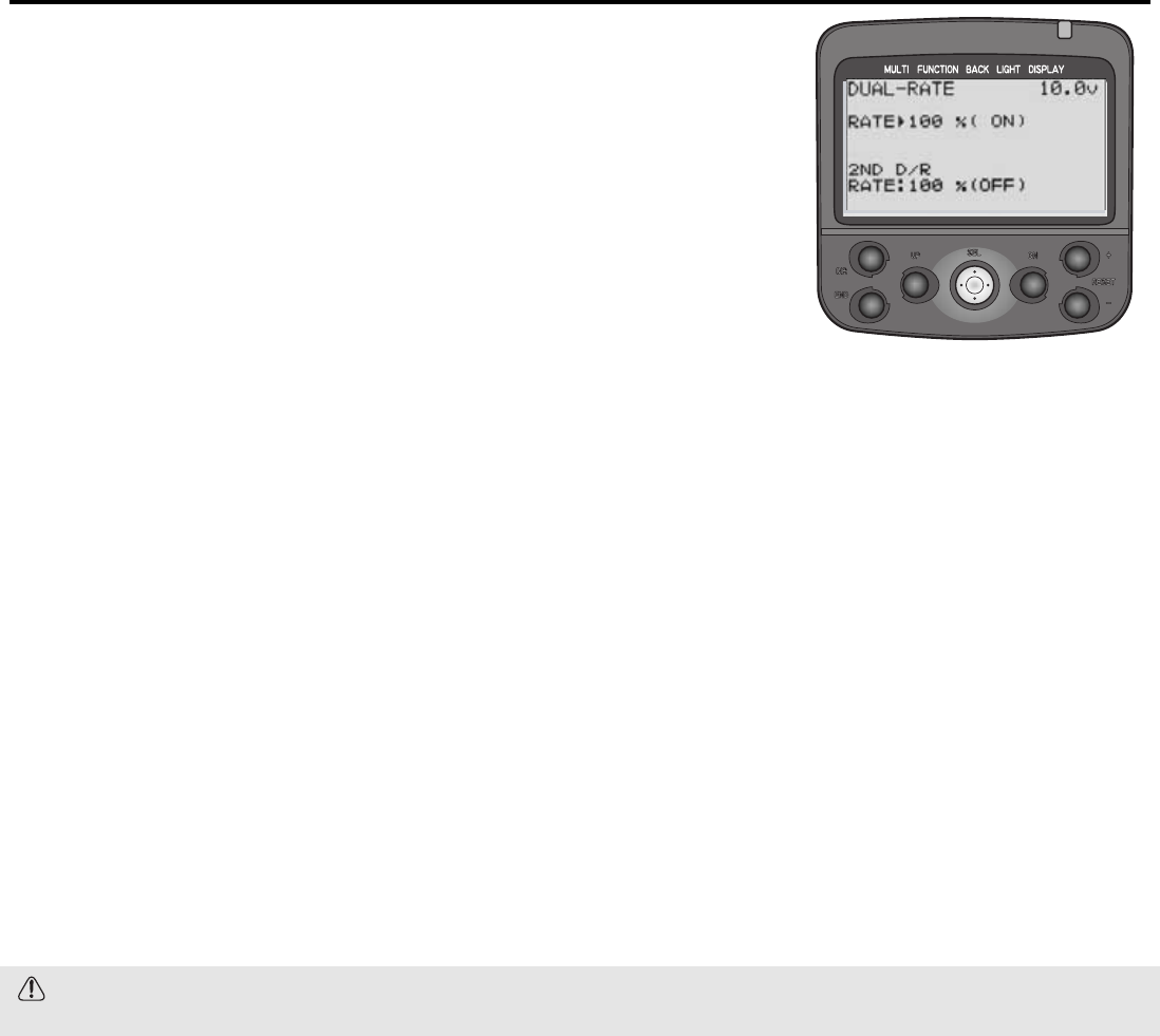
Steering Dual Rate ST-D/R Level LV3 Only
DEFINITIONS:
•Dual Rate, or primary dual rate: Decreases the vehicle’s steering sensitivity
across the entire range. Equivalent of decreasing steering EPA by that percentage.
Assigned to grip dial 1 as a default to allow on-the-course adjustments. If grip dial
is unassigned, dual rate may still be adjusted on-screen. Dual rate is always active,
except when the 2nd dual rate switch is pushed. (3PK’s dual rate is the same as the
9Z’s AFR, and the first rate of dual rate in other aircraft style radio models.)
•Second Dual Rate: A second while-driving rate of servo response, available
with the push of a switch. The 2nd dual rate is meant to be used to temporarily
have more/less servo travel available without having to readjust the dual rate
dial. Second dual rate is proportional to the EPA not the primary dual rate.
Examples: Used for getting away from walls, crashes, a single hairpin turn on an
otherwise non-technical track.
AVAILABLE FOR: Steering only.
ADJUSTABILITY:
• RATE: 0 (no steering at all) to 100% (same as EPA). Default: 100%.
• Switch assignment (to change from primary dual rate to second dual rate): Must be set using FUNC-SW, see pp. 34-
35. Default: no dual rate switch assigned; 2nd dual rate is not usable until a switch is assigned.
• Rate adjustment: Both primary rate and 2nd rate adjustments may be assigned to any dial/digital trim (see FUNC-DIAL,
pp. 34-35) to allow adjustment while driving. If no dial/trim is assigned, then adjustments are made only within the
D/R function. Defaults: D/R on dial 1, 2nd D/R not assigned.
INTERACTIONS:
• EPA affects total travel available to steering servo. Both dual rates are directly proportional to the total EPA.
• Exponential adjusts how much the servo is moved around center without having any effect on the servo travel at full
stick; dual rate uniformly decreases the servo’s movement all along the travel.
• Speed Limiter slows how quickly the servo moves to a certain point without decreasing its overall travel rather than
decreasing the servo’s movement to decrease its sensitivity.
DESIRED END RESULT: Quickly adjust steering overall sensitivity with a dial while driving on the track; have a second
travel rate available for unusual situations, such as a crash.
CAUTION: Dual rate is active as a default and is adjusted from normal setting (100%) with dial 1 unless it is
reassigned by the user.
38
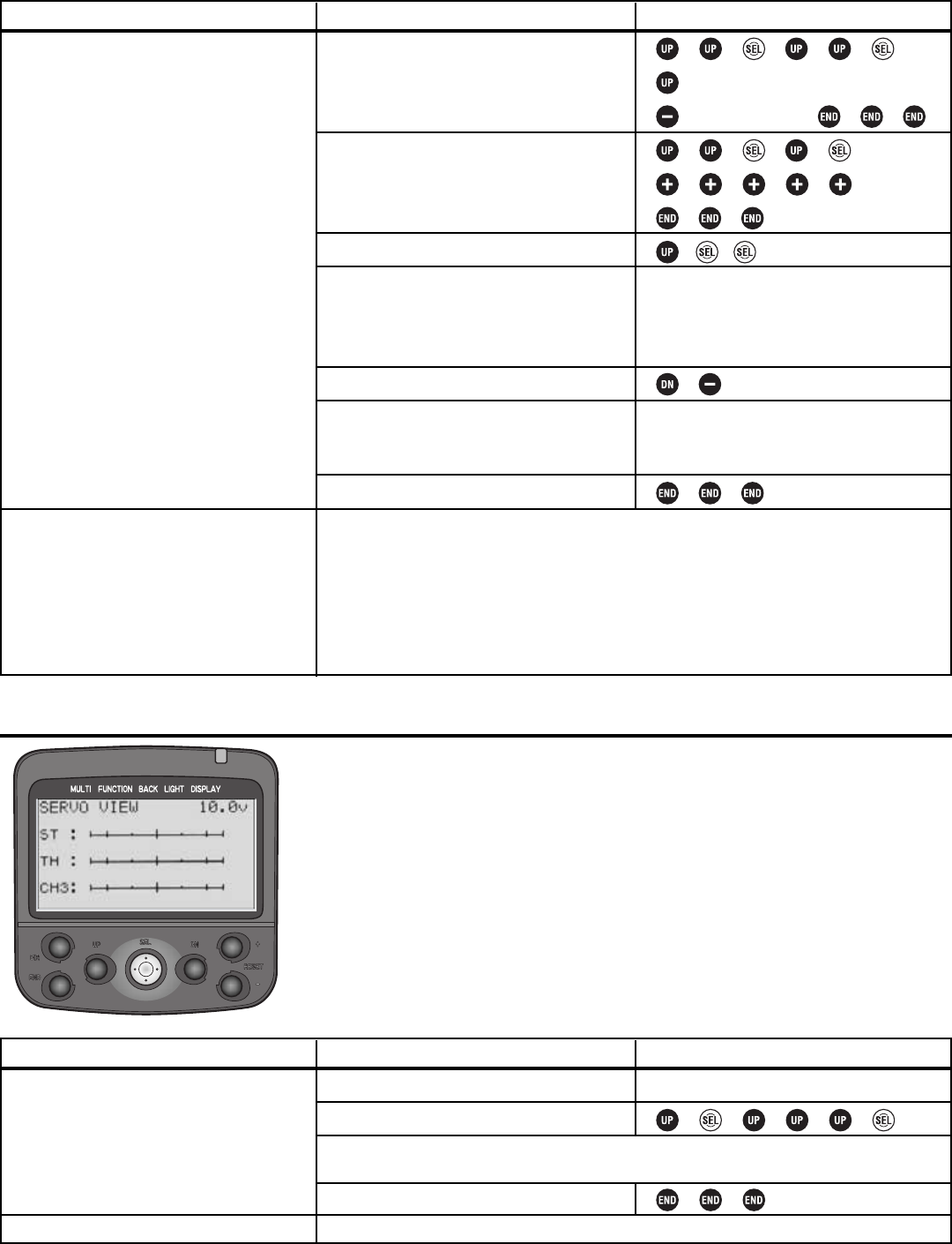
Level LV3 Only Servo View SERVO
DEFINITION: Shows the exact outputs the transmitter is sending to the servos. Allows
for easy testing/experimenting even when receiver and servos are not yet installed.
AVAILABLE FOR: throttle, steering, channel 3.
ADJUSTABILITY: N/A.
INTERACTION: Shows all servo interactions from programming.
DESIRED END RESULT: Confirm programming is having desired result before
radio gear is set up in model.
39
GOAL:
While using LV3:
•Reassign digital trim 1 to the dual rate
adjustment;
•Assign dual rate switching to switch 1;
•Adjust 2nd dual rate to slightly less than
maximum (95%) for quick steering to get
out of tight spots.
(If using LV1 or LV2, first change level
selection, see p. 12.)
Where Next:
STEPS:
Use FUNC-DIAL to assign dual rate to
digital trim 1.
Use FUNC-SW to assign dual rate switching
to switch 1.
Select dual rate.
Test the dual rate adjustment by moving
digital trim 1.
Adjust 2nd dual rate down to 95%.
Test the 2nd dual rate switch by pressing
switch 1.
Close function and menu.
INPUTS:
9 steps to DT1.
12 steps to D/R.
to D/R 2nd.
Move digital trim 1 counterclockwise; see
the rate decrease on-screen. (Note that the
rate per click can be adjusted in the
function dial screen.)
to 95.
Press switch 1 (below the wheel) and notice
2nd D/R Rate changes from OFF to ON, as
primary rate changes from ON to OFF.
Adjust the steering servo’s EPA (EPA): See p. 18.
Adjust steering channel exponential (ST-EXP): See p. 20.
Adjust steering servo response speed (ST-SPEED): See p. 23.
Set up channel 3 control (CH3): See p. 40.
Set up brake mixing for separate front/rear brakes (BRAKE-MIX): See p. 42.
Use servo screen to see exactly how dual rates are performing (SERVO): See below.
GOAL:
View screen after setting up steering dual
rate to confirm switch and dials are
working as planned, while using LV3.
(If using LV1 or LV2, first change level
selection, see p. 12.)
Where Next:
STEPS:
Set up dual rates.
Select servo display.
Close function and menu.
INPUTS:
See page 38.
Return to function and make adjustments as needed, or complete installation in model.
Holding full right turn, adjust dial to see change in total servo throw, then hold dual
rate switch, and notice change in total throw.
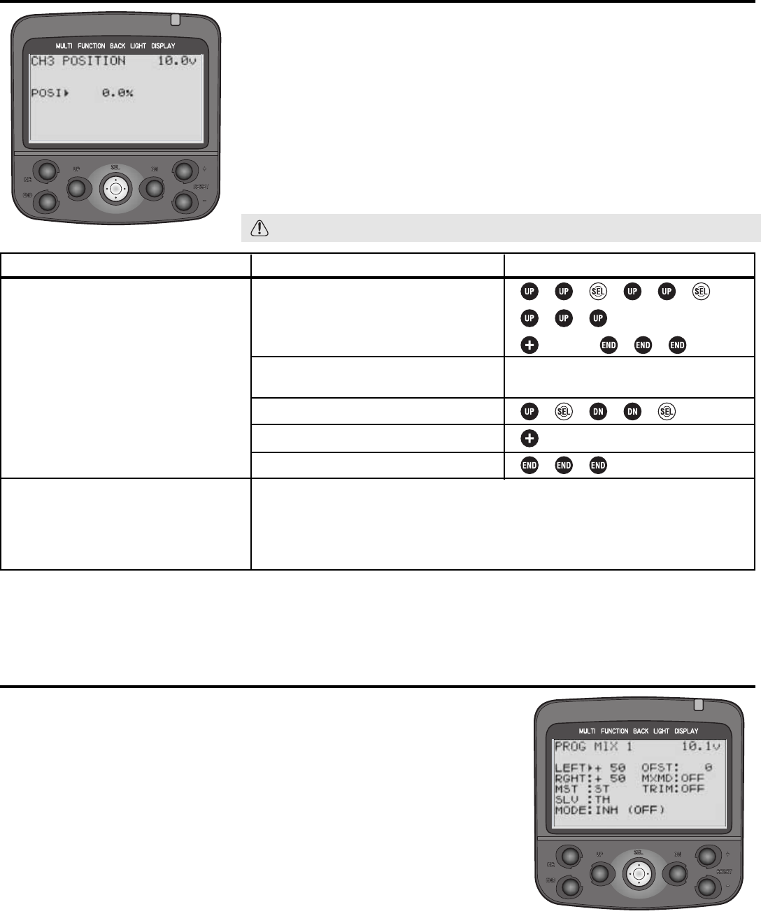
Channel 3 Control CH3-POSI Level LV3 Only
DEFINITION: Sets the default or neutral position for the channel 3 servo.
Defaults to being adjustable with dial 3.
AVAILABLE FOR: channel 3 only.
ADJUSTABILITY: -100% to 0 to +100%. Default adjusts with dial 3, may be
reassigned with FUNC-DIAL (see pp. 34-35).
INTERACTION: Channel 3 position is relative to channel 3’s EPA.
DESIRED END RESULT: Fine tune the channel 3 neutral position. May also be
used to adjust channel 3 to a specific position and leave it there if adjustability
is not assigned to a dial (see FUNC-DIAL, pp. 34-35).
CAUTION: Dial 2 defaults to ATL adjustment, even if user does not realize it.
Programmable Mixes PRG-MIX1, PRG-MIX2 Level LV3 Only
DEFINITIONS:
• Programmable mixing function: Allows user to create mixing between the
steering, throttle and channel 3 servos. Brake mixing is an example of built-in mixes.
• Master: The channel the slave will follow. In brake mixing, the throttle
channel’s braking side.
• Slave: The channel that follows the master. In brake mixing, channel 3 (front brakes).
• Offset: Amount off center to adjust the mix.
• Mix Mode: Selects whether slave moves exactly based upon the master control’s
movement (unmixed) or the master channel’s servo movements after any mixing
(mixed). Brake mixing unmixed means front brakes respond exactly based upon
trigger position while rear braking is changed by ABS, Speed Limiter, etc.
• Trim: Sets whether the slave channel is (ON) or is not (OFF) adjusted with the
master when using the master channel’s trim.
AVAILABLE FOR: Throttle, steering, channel 3.
40
GOAL:
While using LV3:
•Reassign the channel 3 adjustment to
digital trim 3;
•Adjust the channel 3 “center” position from
0 to 18% (with the digital trim centered).
(If using LV1 or LV2, first select level LV3,
see p. 12.)
Where Next:
STEPS:
Use FUNC-DIAL to assign CH3 to digital
trim 3.
While viewing home screen, adjust digital
trim 3 until 3CH reads 0.
Select channel 3 positioning.
Adjust channel 3 position to 18%.
Close function and menu.
INPUTS:
to DT3.
to CH3.
Move trim 3, if necessary, until display
reads 0for 3CH.
to 18.0%.
Adjust channel 3 servo’s EPA (EPA): See p. 18.
Set up brake mixing to use channel 3 for separate front/rear brakes (BRAKE-MIX): See p. 42.
Set up tilt mixing to use channel 3 for boats (BOAT-MODE): See p. 43.
Set up programmable mixes to use channel 3 (PRG-MIX1,2): See below.