Futaba R3001SB-24G Receiver User Manual Rev 01 170118
Futaba Corporation Receiver Rev 01 170118
Futaba >
User Manual-Rev.01(170118)
Applicable systems: Futaba T-FHSS Air 2.4GHz system
R3001SB Specications
T-FHSS Air 2.4GHz system/S.BUS2 port and 1 channel for conventional
system (or S.BUS) receiver
• Dual antenna diversity
• Size: 0.83 x 1.65 x 0.21 in. (21.1 x 41.8 x 5.3 mm)
• Weight: 0.15 oz. (4.2g)
• Power requirement: 4.8V to 7.4V
• Battery F/S Voltage: It sets up with a transmitter
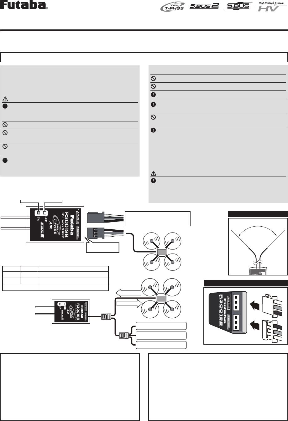
LED Indication
Green Red Status
Off Solid No signal reception
Solid Off Receiving signals
Alternate blink Unrecoverable error (Memory, etc.)
Antenna installation precaution
Do not cut or bundle the receiver antenna wire.
Do not bend the coaxial cable. It causes damage.
The antenna should not be pulled.
Keep the antenna as far away from the motor, ESC
and other noise sources as you possibly can.
Do not touch the antenna to metal, carbon, or other
conductive material.
Be sure that the two antennas are placed at 90 de-
grees to each other.
• The R3001SB has two antennas. In order to maximize signal recep-
tion and promote safe modeling Futaba has adopted a diversity an-
tenna system. This allows the receiver to obtain RF signals on both
antennas and fly problem-free.
Antenna installation for carbon fuse
WARNING
The antenna portion of 30mm tip must be fully ex-
posed.
• Please make sure that the exposed portion won't slide back in the
fuse due to wind pressure or other force during the flight session.
Usage precaution
• Futaba T-FHSS Air system does not work with current Futaba
FASST/FASSTest/S-FHSS/T-FHSS Car system. Futaba FASST/
FASSTest/S-FHSS/T-FHSS Car system and T-FHSS Air system
are not compatible to each other.
WARNING
Wrap the receiver with something soft, such as foam
rubber, to avoid vibration. Moreover, the receiver must
not get wet.
Do not short-circuit the connectors.
Do not expose the receiver to high temperatures.
• The shrink cover could become distorted.
Do not break the tube.
• Could cause a short circuit.
When inserting and removing a connector, hold the
receiver tightly.
• Be careful so that a tube doesn't come off.
Please refer the table below for
LED status vs receiver's condition.
1M23N32502
R3001SB
e.g. Telemetry system
Mode switch
Antenna
S.BUS2 Port
S.BUS Port or CH3 output
conventional system Port
LED
S.BUS2 equipment
* Be sure that when using ESC's regulated output the current capacity of the
ESC meets your usage condition.
* S.BUS/S.BUS2 port: R3001SB can be used with up to 18 channels. However,
it differs according to the transmitter. An unused channel is a neutral signal.
The F/S setting channel at F/S is F/S position. Another, it is Hold signal.
Direction of the connectors
90˚
Antenna installation
The power supply
from S.BUS2 port
is also possible.
R3001SB
T-FHSS Air 2.4GHz System
S.BUS2 Port and
S.BUS Port (or PWM CH3 Port)
Small size, Light weight Receiver
Thank you for purchasing a Futaba R3001SB T-FHSS Air-2.4GHz compatible receiver. The R3001SB receiver features bi-
directional communication with a T-FHSS Air-2.4GHz Futaba transmitter using the S.BUS2 port. Using the S.BUS2 port an
impressive array of telemetry sensors may be utilized. It also includes both standard S.BUS output port or PWM (ch3) output port.
Futaba Telemetry Sensor
Futaba Telemetry Sensor
Futaba Telemetry Sensor
HUB
HUB
Power supply
S.BUS Signal
Compliance Information Statement (for U.S.A.)
This device, trade name Futaba Corporation, model number R3001SB, complies with part15 of the
FCC Rules. Operation is subject to the following two conditions:
(1) This device may not cause harmful interference, and
(2) This device must accept any interference received, including interference that may cause
undesired operation.
CAUTION:
To assure continued FCC compliance:
1. Any changes or modications not expressly approved by the grantee of this device could void the
user's authority to operate the equipment.
2. This equipment complies with FCC radiation exposure limits set forth for an uncontrolled
environment. This equipment should be installed and operated with minimum distance 20cm
between the radiator & your body.
The responsible party of this device compliance is:
Futaba Service Center
3002 N Apollo Drive Suite 1, Champaign, IL 61822 U.S.A.
TEL (217)398-8970 or E-mail: support@futaba-rc.com (Support)
The receiver power
supply can be
connected to any port.
FUTABA CORPORATION
1080 Yabutsuka, Chosei-mura, Chosei-gun, Chiba-ken, 299-4395, Japan
Phone: +81 475 32 6982, Facsimile: +81 475 32 6983
©FUTABA CORPORATION 2017, 1 (1)
WARNING
Do not insert or remove the S.BUS connector while
the receiver power is ON.
Since the S.BUS servo switches the operation mode automatically
according to the type of signal (S.BUS signal/PWM signal) from the re-
ceiver, if the connector is inserted or removed while the power is ON, an
S.BUS connected servo will be erroneously recognized and may stop.
WARNING
Turn on the power on transmitter →receiver in order.
In addition, always check the operation of all the func-
tions before flight.
What is S.BUS?
Different from conventional radio control systems, the S.BUS
system uses data communication to transmit control signals
from a receiver to a servo, gyro, or other S.BUS compatible
devices. This data includes commands such as “move the
channel 3 servo to 15 degrees, move the channel 5 servo to
30 degrees” to multiple devices. The S.BUS devices execute
only those commands for their own set channel. For this
reason, it can be used by connecting multiple servos to the
same signal line.
Link to the transmitter
Easy Link ID allows T-FHSS Air receivers to link to
compatible transmitter without pressing the link button on the
receiver.
1 Bring the transmitter and the receiver close to each
other, within 20 inches (half meter).
2 Turn on the transmitter. Place the transmitter into the
receiver linking mode.
3 Turn on the receiver.
4 The receiver will wait for the linking process to begin
for 3 seconds. Following that it will return to the
normal operation mode.
5 When the LED of the receiver changes from blinking
red to solid green, linking is completed.
(A link waiting state is ended in 3 second.)
* Refer to the transmitters operation manual for complete details on how
to place the transmitter into the linking mode.
WARNING
Do not perform the linking procedure while the mo-
tor's main wire connected or the engine is operating as it
may result in serious injury.
When the linking is complete, please cycle the receiv-
er power and ensure the receiver is properly linked to the
transmitter.
Please power up your system in this order. Transmit-
ter first, followed by the receiver.
If the R3001SB receiver was previously linked to an-
other transmitter, make sure that transmitter is not oper-
ating while linking the receiver to the new transmitter.
* If there are many T-FHSS Air systems turned on in close proximity,
your receiver might have difficulty establishing a link to your transmit-
ter. This is a rare occurrence. However, should another T-FHSS Air
transmitter/receiver be linking at the same time, your receiver could
link to the wrong transmitter. This is very dangerous if you do not no-
tice this situation. In order to avoid the problem,we strongly recom-
mend you to double check whether your receiver is really under con-
trol by your transmitter.
* If the System Type of the transmitter is changed, the receiver will need
to be re-linked to the transmitter.
* Link is required when a new model is made from a model selection.
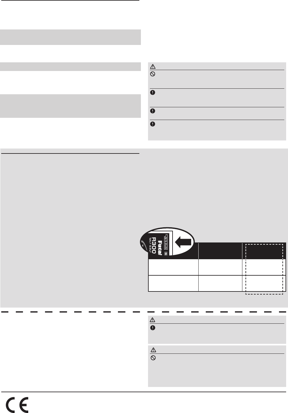
Channel Modes (S.BUS ⇔CH3)
The R3001SB is capable of changing its channel allocations
as described in the table below.
1 Turn on the receiver. (At this moment, the transmitter
should be off.) Then, LED blinks RED in about 3
seconds. Next, wait until it becomes solid RED.
2 Press and hold the Mode switch more than 5
seconds.
3 Release the button when the LED blinks RED and
GREEN simultaneously.
4 The receiver is now in the "Operation CH Set" mode.
At this moment, the LED indicates current set sta-
tus through flashing a pattern that corresponds to the
CH mode.
*Cannot exit this CH setting mode before the operation mode is
xed.
**See the next table that shows correspondence between "CH mode"
and way of ashing LED.
***Default CH mode is "Mode B".
5 By pressing the Mode switch, the operation CH is
switched sequentially as " Mode B" "Mode A" "Mode
B"....
Mode A Mode B
3/S.BUS 3CH S.BUS
Red LED blink 1 time 2 time
R3001SB CH Mode table
Default CH mode
6 The operation mode will be set by pressing the Mode
switch more than 2 seconds at the desired CH
mode.
7 Release the button when the LED blinks RED and
GREEN simultaneously. Then, the operation CH is
fixed.
8 After confirming the operation CH mode is changed,
turn off and back on the receiver power.
*The “Operation CH Set” mode cannot be changed during the
receiver communicates to the transmitter.