User Manual

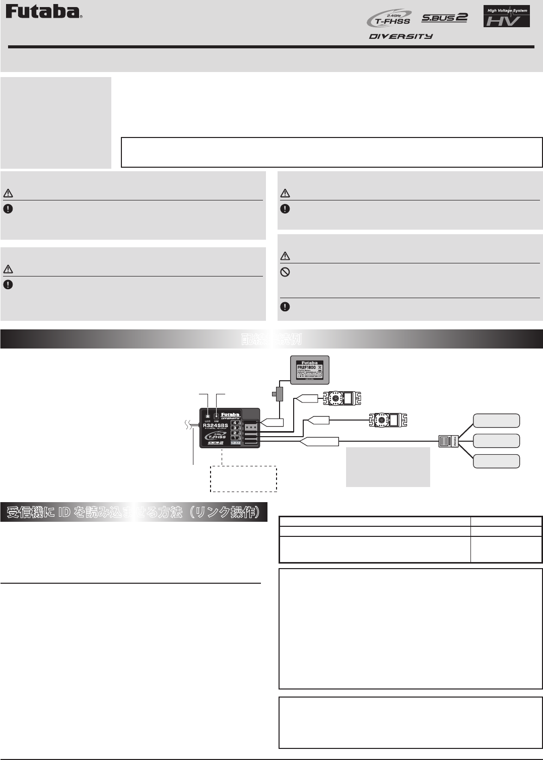
コネクター
"4":CH4 サーボ /(電源)
"3":CH3 サーボ /(電源)
"2":スロットルサーボ /(電源)
"1":ステアリングサーボ /(電源)
"S.BUS2":テレメトリーセンサー /(電源)
下記の操作により、送信機の ID 番号が受信機に読み込まれます。この
ID 番号の識別により、2.4GHz システムは他の送信機からの信号を受け
付けません。この読み込み操作は最初の 1回だけです。次回からは送信機、
受信機の順番に電源を ON にし、受信機の LED が緑点灯すればそのま
ま使用可能です。
リンク操作
1 送信機と受信機を 50cm 以内に近付けます。
※ アンテナ同士をできるだけ近接します。
2 送信機 /受信機の電源を ON。
3 送信機を送信機の取扱説明書にしたがってリンクモードにします。
4 受信機のリンクスイッチを約2秒押します。LED が赤点滅→緑赤→緑 (赤)点
灯となり送信機画面に受信機の ID が表示されます。送信機にエラー画面が出た
場合リンクが失敗しています。再度リンクさせてください。
5 T4PLS、T4GRS の場合送信機の電源を OFF →ON してください。受信機の
LED が緑に点灯すれば OK です。
※ リンク操作時、周囲で他の T-FHSS-2.4GHz システムがリンク操作されている場合、そ
れらの送信機のうちの 1台とリンクしてしまう場合があります。このため、リンク操
作が完了したら、必ず動作を確認してください。
受信機に ID を読み込ませる方法(リンク操作)
カー用 T-FHSS-2.4GHz 方式 双方向通信 S.BUS 2
ダイバーシティーアンテナ 4 チャンネル受信機
動作モード切替時の注意
※R324SBS は電源を入れた時点で送
信機の設定が、ハイスピード (HIGH)
またはノーマル (NORM) モードの判
別をし、電源を切るまではそのモー
ドで動作します。送信機のモードを
変更した場合、受信機電源を入れ直
した時点で動作可能となります。
この度は、T-FHSS-2.4GHz 方式、4チャンネル受信機 R324SBS をお買上げいただきまして誠にありがとうございます。ご使用の前に、
本書ならびにご使用の送信機の取扱説明書をお読みの上、正しく安全にお使いください。また、お読みになられた後も大切に保管し
てください。この受信機は弊社 T-FHSS 方式対応の送信機と組み合わせてのみ使用できます。送信機側の設定により、ハイスピードモー
ド(高速応答動作)/ノーマルモードを選択できます。ただし、ハイスピードモード時は、デジタルサーボ(ブラシレスサーボを含む)
専用となります。ノーマルモード時は、アナログサーボおよびデジタルサーボが使用可能です。R324SBS は、双方向通信に対応して
います。走行中の受信機の電源電圧を送信機で確認できる他、別売のテレメトリーセンサーを接続することにより車体の温度、回転
数などのデータを送信機に送ることができます。さらにダイバーシティーアンテナを装備し受信性能が向上されています。
R324SBS
取扱説明書
●
この R324SBS はFutaba 製 2.4GHz T-FHSS システム送信機のみに対応します。
※Futaba T-FHSSシステムは、Futaba S-FHSS, FHSS, FASSTest, FASST,T-FHSS Airシステムの送信機との組み合わせでは動作できません。
電源コネクター
電源は空いているコネクター1つに接
続します。どのコネクターでもかまい
ません。すべて使用している場合、フ
タマタコードで接続してください。
本製品は、特定無線設備の技術基準適合証明を取得しています。
・証明ラベルを剥がさないでください。
・分解して修理・変更・改造しないでください。
・証明ラベルを剥がしたり、お客様が修理・変更・改造したものは不法無線局と
して法律により罰せられることがあります。
リンクの注意
警告
リンク操作時は動力用モーターが接続された状態やエンジンがかかった状態で
は行わないでください。
■不意にモーターが回転したり、エンジンが吹け上がったりすると大変危険です。
リンク操作が完了したら、一旦受信機の電源を OFF とし、リンクした送信機
で操作ができることを確認してください。
双葉電子工業株式会社 電子機器営業部 TEL.(0475)32-6981
〒299-4395 千葉県長生郡長生村薮塚 1080
©FUTABA CORPORATION 2017 年2月 初版
内部アンテナ
※受信機上面に機器を
貼付けないでください。
※カットしないで
ください。
外部アンテナ
三又ハブ
温度センサー
回転センサー
電圧センサー
Link スイッチ
バッテリー
テレメトリーセンサー
ステアリングサーボ
スロットルサーボ
CH4 CH1
各テレメトリーセンサー
はハブやフタマタコード
でまとめて S.BUS2 ポー
トへ接続します。
S.BUS2
CH2
( 空いているコネクターに接続します。)
※すべてのコネクターを使用している場合はフタマタコードを使用して
いずれかの CH か S.BUS2 コネクターに接続してください。
LED
配線接続例
サーボについて
注意
ハイスピードモード時、弊社デジタルサーボ専用となります。
■アナログサーボを使用するとサーボや受信機の故障の原因となります。
※弊社製以外の EP アンプをご使用の場合、ハイスピードモードで動作しない場合があります。
この場合は、ノーマルモードに切り替えてご使用ください。
アンテナの注意
注意
受信機上面にステッカーや電子機器を貼り付けないでください。
■外付けアンテナとケース内部アンテナのダイバーシティー方式の受信機です。受信機上面
に障害物があると操作不能になる危険性があります。
使用条件について
注意
R324SBS は必ず下記条件で使用して下さい。
■受信機使用電源:3.7 V~ 7.4 Vの範囲で接続するサーボの規格にあわせる。(乾電池は使用不可)
■送信機の RX タイプ設定:T-FHSS (HIGH / NORM)
■防振対策および防水対策を十分におこなう。
R324SBS 仕様
(T-FHSS-2.4GHz 方式、4チャンネル受信機)
受信周波数 : 2.4GHz 帯
システム : T-FHSS システム ダイバーシティーアンテナ
ノーマル/ハイスピードモード(自動認識)S.BUS 2 対応
使用電源規格電圧 : 3.7V ~7.4V
F/S 機能・バッテリー F/S 機能 : 各チャンネルに送信機にて設定可能
バッテリー F/S : 電圧送信機にて設定可能
サイズ : 35.1x23.2x12.5mm(突起部を除く)
重量 : 8.3g
※ BEC 電源を使用する場合、容量がご使用のサーボ等の条件に合っていること
が必要です。また、乾電池は使用しないでください。誤動作の原因となります。
受信機 LED の状態表示
信号が受信されていない状態 赤点灯
受信状態 OK(ID 設定完了) 緑点灯
自動復旧できない異常(EEPROM 異常、その他)電源再投
入で回復できない場合は弊社カスタマーサービスへ点検・
修理依頼してください。
赤 / 緑交互点灯
1M23N17492

Link Procedure
Each transmitter has an individually assigned, unique ID code. In order to start
operation, the receiver must be linked with the ID code of the transmitter with
which it is being paired. Once the link is made, the ID code is stored in the
receiver and no further linking is necessary unless the receiver is to be used with
another transmitter.
1 Place the transmitter and the receiver close to each other within
half (0.5) meter.
2 Place the transmitter into the linking mode, and turn on the
receiver.
3 During countdown, push the receiver tact switch for
approximately 2 seconds. The LED will begin to blink red. After
the receiver LED switches from blinking red to green →green
(red) steady light, If the transmitter and receiver are linked
normally, set the power switch to the OFF position and then
return it to the PWR ON position. If the receiver LED lights
green, linking was successful. (T4PLS,T4GRS : set the power
switch to the OFF position and then return it to the PWR ON
position.) Actually check servo operation.
* Please refer to the table below for LED status and receiver condition.
* Refer to the transmitters operation manual for complete details on how to place the transmitter
into the linking mode.
* If there are many T-FHSS systems turned on in close proximity, your receiver might have
difficulty establishing a link to your transmitter. This is a rare occurrence. However, should
another T-FHSS transmitter/receiver be linking at the same time, your receiver could link to the
wrong transmitter. This is very dangerous if you do not notice this situation. In order to avoid
the problem,we strongly recommend you to double check whether your receiver is really under
control by your transmitter.
WARNING
After the linking is done, please cycle receiver power and check if the
receiver to be linked is really under the control by the transmitter to be linked.
Do not perform the linking procedure with motor's main wire connected
or with the engine operating as it may result in serious injury.
Operating Precautions:
Once the R324SBS detects the T-FHSS normal
mode or T-FHSS high speed mode, the detected
mode is locked as long as the power is ON.
When need to change the mode, please
cycle power.
Note: The R324SBS is compatible with the T-FHSS system transmitters.
The receiver type setting of the transmitter is set in T-FHSS.
*Futaba T-FHSS system does not work with current Futaba S-FHSS/FHSS/FASSTest/FASST /T-FHSS Air system.
Usage condition on "High Speed mode"
CAUTION
When using the high-speed mode, use a Futaba digital servo
(including brushless servo). Analog servos cannot be used.
• The use of analog servos may cause servo trouble.
1M23N17492
T-FHSS-2.4GHz System Diversity antenna
S.BUS2, 4-Channel Receiver for Model Car
Thank you for purchasing the R324SBS
receiver. The R324SBS is designed for use
with the Futaba T-FHSS system transmitter.
The R324SBS receiver has adopted the newly
developed bidirectional communication
system "T-FHSS".
• Telemetry system
With the telemetry system, the running status can be displayed at the transmitter. The telemetry data can be checked at the
transmitter by connecting the telemetry sensor sold separately to the S.BUS2 connector of the R324SBS receiver.
• Normal mode/High Speed mode
The "Normal mode" accepts any type of servos or the peripheral. The "High Speed mode" only accepts the digital servos,
including BLS series, and most peripheral equipments such as the brushless ESCs. Please pay special attention to the information
contained within this manual and transmitter's manual in order to have a pleasant running experience.
• Diversity antenna equipment
R324SBS
WARNING
NEVER use dry batteries for the power supply of the R324SBS as
this may cause difficulties with the receiver's operation.
Wrap the receiver with something soft, such as foam rubber, to avoid
vibration. Do not splash water over the receiver.
Since the receiver generates a certain amount of heat, install the
place with good ventilation.
Do not put any conductive equipment/sticker on the antenna part.
(Receiver top)
• Otherwise, the operating range may become shorter.
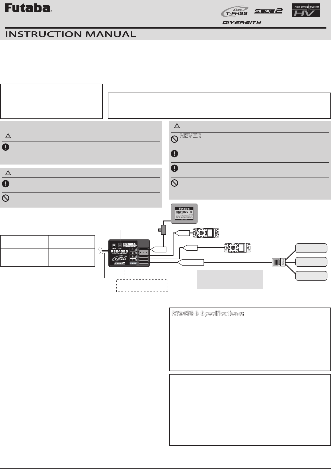
No signal reception LED: Red
Receiving signals LED: Green
Unrecoverable fail-
ure (EEPROM,etc.)
LED: Red and
Green turn on
alternately
FUTABA CORPORATION
1080 Yabutsuka, Chosei-mura, Chosei-gun, Chiba-ken, 299-4395, Japan
Phone: +81 475 32 6982, Facsimile: +81 475 32 6983
©FUTABA CORPORATION 2017, 2 (1)
R324SBS Specifications:
(T-FHSS system, S.BUS2, 4-channel receiver)
• Receiving on 2.4GHz band
• System:
T-FHSS system
At Normal/High speed mode (auto detection)
•
Power requirement Operating voltage: 3.7V-7.4V
• F/S and Battery F/S function:It is set according to the transmitter used.
• Battery F/S voltage: Set it with the transmitter arbitrarily.
• Size: 1.38x0.91x0.49” (35.1x23.2x12.5mm)
• Weight: 0.29oz. (8.3g)
HUB
Battery
Steering servo
Throttle servo
Collect many telemetry
sensors by HUB and connect
them to S.BUS2 port.
(It connects with port which is not used.)
*When all the ports are used, connect
a battery using HUB or Y-harness.
Built-in antenna
*Receiver top is clean.
Out side Antenna
Link Switch
CH4 CH1
S.BUS2
CH2
LED
Temperature
sensor
RPM sensor
Voltage sensor
Telemetry sensors
(Option)
*Don't cut or bundle
the receiver
antenna wire. The Example of Connection
LED Indication
Compliance Information Statement (for U.S.A.)
This device, trade name Futaba Corporation, model number R324SBS, complies with part15 of the FCC Rules.
Operation is subject to the following two conditions:
(1) This device may not cause harmful interference, and
(2) This device must accept any interference received, including interference that may cause undesired operation.
CAUTION:
To assure continued FCC compliance:
1. Any changes or modications not expressly approved by the grantee of this device could void the user's authority
to operate the equipment.
2. This equipment complies with FCC radiation exposure limits set forth for an uncontrolled environment. This
equipment should be installed and operated with minimum distance 20cm between the radiator & your body.
The responsible party of this device compliance is:
Futaba Service Center
3002 N Apollo Drive Suite 1, Champaign, IL 61822 U.S.A.
TEL (217)398-8970 or E-mail: support@futaba-rc.com (Support)