Futaba T18MZWC-24G Radio Control User Manual 1
Futaba Corporation Radio Control 1
UserManual.wiki
>
Futaba
>
T18MZWC-24G User Manual
>
User Manual 1
Contents
1.
User Manual 1
2.
User Manual 2
User Manual 1
Navigation menu
Upload a User Manual
Namespaces
Wiki Guide
HTML
PDF
Info
Views
User Manual
Discussion / Help
Navigation
![4<Introduction >,1752'8&7,21Thank you for purchasing a Futaba® FASSTest-2.4GHz*18MZ-WC series digital proportional R/C system. This system is extremely versatile and may be used by beginners and pros alike. In order for \RXWRPDNHWKHEHVWXVHRI\RXUV\VWHPDQGWRÀ\VDIHO\SOHDVHUHDGWKLVPDQXDOFDUHIXOO\ ,I \RXKDYHDQ\GLI¿FXOWLHVZKLOHXVLQJ\RXUV\VWHPSOHDVHFRQVXOWWKHPDQXDORXURQOLQH)UHTXHQWO\$VNHG4XHVWLRQVRQWKHZHESDJHVUHIHUHQFHGEHORZ\RXUKREE\GHDOHURUWKH)XWDED6HUYLFH&HQWHU'XH WR XQIRUHVHHQ FKDQJHV LQ SURGXFWLRQ SURFHGXUHV WKH LQIRUPDWLRQ FRQWDLQHG LQ WKLV PDQXDO LVVXEMHFWWRFKDQJHZLWKRXWQRWLFH6XSSRUWDQG6HUYLFH,WLVUHFRPPHQGHGWRKDYH\RXU)XWDEDHTXLSPHQWVHUYLFHGDQQXDOO\GXULQJ\RXUhobby’s “off season” to ensure safe operation.,11257+$0(5,&$3OHDVHIHHOIUHHWRFRQWDFWWKH)XWDED6HUYLFH&HQWHUIRUDVVLVWDQFHLQRSHUDWLRQXVHDQGSURJUDPPLQJ3OHDVHEHVXUHWRUHJXODUO\YLVLWWKH0=:&)UHTXHQWO\$VNHG4XHVWLRQVZHEVLWHDWZZZIXWDEDUFFRPIDT 7KLV SDJH LQFOXGHV H[WHQVLYH SURJUDPPLQJ XVH VHW XS DQG VDIHW\ LQIRUPDWLRQ RQ WKH18MZ-WC radio system and is updated regularly. Any technical updates and US manual corrections ZLOO EH DYDLODEOH RQ WKLV ZHE SDJH ,I \RX GR QRW ¿QG WKH DQVZHUV WR \RXU TXHVWLRQV WKHUH SOHDVHsee the end of our F.A.Q. area for information on contacting us via email for the most rapid and convenient response. 'RQ¶WKDYH,QWHUQHWDFFHVV",QWHUQHWDFFHVVLVDYDLODEOHDWQRFKDUJHDWPRVWSXEOLFOLEUDULHVVFKRROVDQGRWKHUSXEOLFUHVRXUFHV:H¿QGLQWHUQHWVXSSRUWWREHDIDEXORXVUHIHUHQFHIRUPDQ\PRGHOHUVDVLWHPVFDQEHSULQWHGDQGVDYHGIRUIXWXUHUHIHUHQFHDQGFDQEHDFFHVVHGDWDQ\KRXURIWKHGD\QLJKWZHHNHQGRUKROLGD\,I\RXGRQRWZLVKWRDFFHVVWKHLQWHUQHWIRULQIRUPDWLRQKRZHYHUGRQ¶WZRUU\Our support teams are available Monday through Friday 8-5 Central time to assist you. )256(59,&(21/<Futaba Service Center 1$SROOR'ULYH6XLWH&KDPSDLJQ,/Phone: 217-398-0007ZZZIXWDEDUFFRPVHUYLFHKWPOEmail: futabaservice@hobbico.com )256833257352*5$00,1*$1'86(548(67,2163OHDVHVWDUWKHUHIRUDQVZHUVWRPRVWTXHVWLRQVZZZIXWDEDUFFRPIDTFax: 217-398-7721Phone: 217-398-8970 option 22876,'(1257+$0(5,&$3OHDVH FRQWDFW \RXU )XWDED LPSRUWHU LQ \RXU UHJLRQ RI WKH ZRUOG WR DVVLVW \RX ZLWK DQ\ TXHVWLRQVproblems or service needs. 3OHDVH UHFRJQL]H WKDW DOO LQIRUPDWLRQ LQ WKLV PDQXDO DQG DOO VXSSRUW DYDLODELOLW\ LV EDVHG XSRQ WKHV\VWHPVVROG LQ1RUWK$PHULFD RQO\ 3URGXFWV SXUFKDVHG HOVHZKHUH PD\YDU\$OZD\V FRQWDFW\RXUregion’s support center for assistance.](https://usermanual.wiki/Futaba/T18MZWC-24G.User-Manual-1/User-Guide-2898093-Page-4.png)
![5<Introduction >$SSOLFDWLRQ([SRUWDQG0RGL¿FDWLRQ7KLVSURGXFWPD\EHXVHGIRUPRGHODLUSODQHRUVXUIDFHERDWFDUURERWXVH,WLVQRWLQWHQGHGIRUuse in any application other than the control of models for hobby and recreational purposes. The product is subject to regulations of the Ministry of Radio/Telecommunications and is restricted XQGHU-DSDQHVHODZWRVXFKSXUSRVHV2. Exportation precautions: D:KHQWKLVSURGXFWLVH[SRUWHGIURPWKHFRXQWU\RIPDQXIDFWXUHLWVXVHLVWREHDSSURYHGE\WKHODZV JRYHUQLQJ WKH FRXQWU\ RI GHVWLQDWLRQ ZKLFK JRYHUQ GHYLFHV WKDW HPLW UDGLR IUHTXHQFLHV ,IWKLVSURGXFWLVWKHQUHH[SRUWHGWRRWKHUFRXQWULHVLWPD\EHVXEMHFWWRUHVWULFWLRQVRQVXFKH[SRUW3ULRUDSSURYDORIWKHDSSURSULDWHJRYHUQPHQWDXWKRULWLHVPD\EHUHTXLUHG,I\RXKDYHSXUFKDVHGWKLVSURGXFWIURPDQ H[SRUWHU RXWVLGH\RXUFRXQWU\DQGQRW WKH DXWKRUL]HG)XWDEDGLVWULEXWRULQ\RXUFRXQWU\SOHDVHFRQWDFWWKHVHOOHULPPHGLDWHO\WRGHWHUPLQHLI VXFK H[SRUWUHJXODWLRQVKDYHbeen met. E8VHRIWKLVSURGXFWZLWKRWKHUWKDQPRGHOVPD\EHUHVWULFWHGE\([SRUWDQG7UDGH&RQWURO5HJXODWLRQVDQGDQDSSOLFDWLRQIRUH[SRUWDSSURYDOPXVWEHVXEPLWWHG7KLVHTXLSPHQWPXVWQRWEHXWLOL]HGWRRSHUDWHHTXLSPHQWRWKHUWKDQUDGLRFRQWUROOHGPRGHOV 0RGLILFDWLRQ DGMXVWPHQW DQG UHSODFHPHQW RI SDUWV )XWDED LV QRW UHVSRQVLEOH IRU XQDXWKRUL]HGPRGL¿FDWLRQDGMXVWPHQWDQGUHSODFHPHQWRISDUWVRQWKLVSURGXFW$Q\VXFKFKDQJHVPD\YRLGWKHZDUUDQW\Compliance Information Statement (for U.S.A.)7KLVGHYLFHWUDGH QDPH )XWDED&RUSRUDWLRQFRPSOLHVZLWK SDUW RIWKH)&&5XOHV 2SHUDWLRQ LVVXEMHFWWRWKHIROORZLQJWKUHHFRQGLWLRQV7KLVGHYLFHPD\QRWFDXVHKDUPIXOLQWHUIHUHQFHDQG7KLVGHYLFHPXVWDFFHSWDQ\LQWHUIHUHQFHUHFHLYHGLQFOXGLQJLQWHUIHUHQFHWKDWPD\FDXVHXQGHVLUHGoperation.7KLVPRGXOHPHHWVWKHUHTXLUHPHQWVIRUDPRELOHGHYLFHWKDWPD\EHXVHGDWVHSDUDWLRQGLVWDQFHVof more than 20cm from human body.7RPHHWWKH5)H[SRVXUHUHTXLUHPHQWVRIWKH)&&WKLVGHYLFHVKDOOQRWEHFRORFDWHGZLWKDQRWKHUtransmitting device.The responsible party of this device compliance is:Futaba Service Center1$SROOR'ULYH6XLWH&KDPSDLJQ,/86$7(/RU(PDLOVXSSRUW#KREELFRFRP6XSSRUW7(/RU(PDLOIXWDEDVHUYLFH#KREELFRFRP6HUYLFH7KH 5%5& 6($/ RQ WKH QLFNHOFDGPLXP EDWWHU\ FRQWDLQHG LQ )XWDED SURGXFWVindicates that Futaba Corporation of America is voluntarily participating in an LQGXVWU\ZLGH SURJUDP WR FROOHFW DQG UHF\FOH WKHVH EDWWHULHV DWWKHHQGRIWKHLUXVHIXOOLYHVZKHQWDNHQRXWRIVHUYLFHZLWKLQWKH8QLWHG6WDWHV7KH5%5&program provides a convenient alternative to placing used nickel-cadmium EDWWHULHVLQWRWKHWUDVKRUPXQLFLSDOZDVWHV\VWHPZKLFKLVLOOHJDOLQVRPHDUHDVIRU86$<RXPD\FRQWDFW\RXUORFDOUHF\FOLQJFHQWHUIRULQIRUPDWLRQRQZKHUHWRUHWXUQWKHVSHQWEDWWHU\Please call 1-800-8BATTERY for information on Ni-Cd battery recycling in your area. Futaba Corporation involvement in this program is part of its commitment to protecting our environment and conserving natural resources. *RBRC is a trademark of the Rechargeable Battery Recycling Corporation.](https://usermanual.wiki/Futaba/T18MZWC-24G.User-Manual-1/User-Guide-2898093-Page-5.png)
![7<Introduction >%DWWHU\Charge the batteries!6HH&KDUJLQJWKHEDWWHULHVIRUGHWDLOV$OZD\VUHFKDUJHWKHWUDQVPLWWHUDQGUHFHLYHUEDWWHULHVEHIRUHHDFKÀ\LQJVHVVLRQ$ORZEDWWHU\ZLOOVRRQGLHSRWHQWLDOO\FDXVLQJORVVRIFRQWURODQGDFUDVK:KHQ\RXEHJLQ\RXUÀ\LQJVHVVLRQUHVHW\RXU70=:&¶VEXLOWLQWLPHUDQGGXULQJWKHVHVVLRQSD\DWWHQWLRQWRWKHGXUDWLRQRIXVDJH6WRSÀ\LQJORQJEHIRUH\RXUEDWWHULHVEHFRPHORZRQFKDUJH'RQRWUHO\RQ\RXUUDGLR¶VORZEDWWHU\ZDUQLQJV\VWHPVLQWHQGHGRQO\DVDSUHFDXWLRQWRWHOO\RXZKHQWRUHFKDUJH$OZD\VFKHFN\RXUWUDQVPLWWHUDQGUHFHLYHUEDWWHULHVSULRUWRHDFKÀLJKWWhere to Fly :HUHFRPPHQGWKDW\RXÀ\DWDUHFRJQL]HGPRGHODLUSODQHÀ\LQJ¿HOG<RXFDQ¿QGPRGHOFOXEVDQG¿HOGVE\DVNLQJ\RXUQHDUHVWKREE\GHDOHURULQWKH86E\FRQWDFWLQJWKH$FDGHP\RI0RGHOAeronautics.<RXFDQDOVRFRQWDFWWKHQDWLRQDO$FDGHP\RI0RGHO$HURQDXWLFV$0$ZKLFKKDVPRUHWKDQFKDUWHUHG FOXEV DFURVV WKH FRXQWU\ 7KURXJK DQ\ RQH RI WKHP LQVWUXFWRU WUDLQLQJ SURJUDPV DQGLQVXUHGQHZFRPHUWUDLQLQJDUHDYDLODEOH&RQWDFWWKH$0$DWWKHDGGUHVVRUWROOIUHHSKRQHQXPEHUEHORZ$FDGHP\RI0RGHO$HURQDXWLFV(DVW0HPRULDO'ULYH0XQFLH,17HOH)D[RUYLDWKH,QWHUQHWDWKWWS??ZZZPRGHODLUFUDIWorg$OZD\VSD\SDUWLFXODUDWWHQWLRQWRWKHÀ\LQJ¿HOG¶VUXOHVDVZHOODVWKHSUHVHQFHDQGORFDWLRQRIVSHFWDWRUVWKHZLQGGLUHFWLRQDQGDQ\REVWDFOHVRQWKH¿HOG%HYHU\FDUHIXOÀ\LQJLQDUHDVQHDUSRZHUOLQHVWDOOEXLOGLQJVRUFRPPXQLFDWLRQIDFLOLWLHVDVWKHUHPD\EHUDGLRLQWHUIHUHQFHin their vicinity.](https://usermanual.wiki/Futaba/T18MZWC-24G.User-Manual-1/User-Guide-2898093-Page-7.png)
![8<Introduction >/LWKLXPSRO\PHU/LSR%DWWHU\6DIHW\DQG+DQGOLQJLQVWUXFWLRQVIMPORTANT!Use only the Futaba special chargerLQFOXGHGZLWKWKLVVHWRURWKHUFKDUJHUVDSSURYHGE\Futaba to charge the LiSREDWWHULHVLQWKH70=:&WUDQVPLWWHULQFOXGHGZLWKWKLVVHW,WLVLPSRUWDQWWRXQGHUVWDQGWKHRSHUDWLQJFKDUDFWHULVWLFVRI/LSREDWWHULHV$OZD\VUHDGWKHVSHFL¿FDWLRQV SULQWHG RQ WKH ODEHO RI \RXU /LSR EDWWHU\ DQG FKDUJHU SULRU WR XVH )DLOXUH WR IROORZWKH SURFHHGLQJ SUHFDXWLRQV FDQ TXLFNO\ UHVXOW LQ VHYHUH SHUPDQHQW GDPDJH WR WKH EDWWHULHV DQG LWVsurroundings and possibly result in a FIRE!,03257$1735(&$87,216Do not attempt to disassemble /LSR packs or cells. 'RQRWDOORZ/LSRFHOOVWRFRPHLQFRQWDFWZLWKPRLVWXUHRUZDWHUDWDQ\WLPH$OZD\V SURYLGH DGHTXDWH YHQWLODWLRQ DURXQG /LSR EDWWHULHV GXULQJ FKDUJH GLVFKDUJH ZKLOH LQXVHDQGGXULQJVWRUDJHDo not leave a /LSREDWWHU\XQDWWHQGHGDWDQ\WLPHZKLOHEHLQJFKDUJHGRUGLVFKDUJHGDo not attempt to charge /LSREDWWHULHVZLWKDFKDUJHUWKDWLV127GHVLJQHGIRU/LSREDWWHULHVas permanent damage to the battery and charger could result.$OZD\VFKDUJH/LSREDWWHULHVLQD¿UHSURRIORFDWLRQ'RQRWFKDUJHRUGLVFKDUJH/LSR batteries RQFDUSHWDFOXWWHUHGZRUNEHQFKQHDUSDSHUSODVWLFYLQ\OOHDWKHURUZRRGRULQVLGHDQ5&PRGHORUIXOOVL]HGDXWRPRELOH0RQLWRUWKHFKDUJHDUHDZLWKDVPRNHRU¿UHDODUPDo not charge /LSREDWWHULHVDWFXUUHQWVJUHDWHUWKDQWKH³&´UDWLQJRIWKHEDWWHU\³&´HTXDOVWKHUDWHGFDSDFLW\RIWKHEDWWHU\'R QRW DOORZ /LSR FHOOV WR RYHUKHDW DW DQ\ WLPH &HOOV ZKLFK UHDFK JUHDWHU WKDQ GHJUHHV)DKUHQKHLW&VKRXOGEHSODFHGLQD¿UHSURRIORFDWLRQ/LSRFHOOVZLOOQRWFKDUJHIXOO\ZKHQWRRFROGRUVKRZIXOOFKDUJH,WLVQRUPDOIRU WKH EDWWHULHVWREHFRPHZDUPGXULQJ FKDUJLQJEXWLIWKH FKDUJHURUEDWWHU\EHFRPHVH[FHVVLYHO\KRWGLVFRQQHFWWKHEDWWHU\IURPWKHFKDUJHULPPHGLDWHO\$OZD\VLQVSHFWDEDWWHU\ZKLFKKDVSUHYLRXVO\RYHUKHDWHGIRUSRWHQWLDOGDPDJHDQGGRQRWUHXVHLI\RXVXVSHFWLWKDVEHHQGDPDJHGLQDQ\ZD\'RQRWXVHD /LSR EDWWHU\LI\RXVXVSHFWSK\VLFDOGDPDJH KDV RFFXUUHG WR WKHSDFN&DUHIXOO\LQVSHFW WKH EDWWHU\ IRU HYHQ WKH VPDOOHVW RI GHQWV FUDFNV VSOLWV SXQFWXUHV RU GDPDJH WR WKHZLULQJDQGFRQQHFWRUV'2127DOORZWKHEDWWHU\¶VLQWHUQDOHOHFWURO\WHWRJHWLQWR H\HV RU RQVNLQ²ZDVKDIIHFWHGDUHDVLPPHGLDWHO\LIWKH\FRPHLQFRQWDFWZLWKWKHHOHFWURO\WH,ILQGRXEWSODFHWKHEDWWHU\LQD¿UHSURRIORFDWLRQIRUDWOHDVWPLQXWHV'RQRWVWRUHEDWWHULHVQHDUDQRSHQÀDPHRUKHDWHU'R QRW GLVFKDUJH /LSR EDWWHULHV DW FXUUHQWV ZKLFK H[FHHG WKH GLVFKDUJH FXUUHQW UDWLQJ RI WKHbattery.$OZD\VVWRUH/LSRFHOOVSDFNVLQDVHFXUHORFDWLRQDZD\IURPFKLOGUHQ1HYHUUHPRYHWKH6'FDUGRUWXUQRIISRZHUZKLOHHQWHULQJGDWD1HYHUVWRUHWKH6'FDUGZKHUHLWPD\be subject to strong static electricity or PDJQHWLF¿HOGVDo not expose the SD card to direct VXQOLJKWH[FHVVLYHKXPLGLW\RUFRUURVLYHenvironments.'RQRWH[SRVHWKH6'FDUGWRGLUWPRLVWXUHZDWHURUÀXLGVRIDQ\NLQGBe certain to insert the SD card in the correct direction.6HFXUH'LJLWDO6'0HPRU\&DUG+DQGOLQJ,QVWUXFWLRQV6'FDUGLVQRWLQFOXGHGZLWKWKLVVHW](https://usermanual.wiki/Futaba/T18MZWC-24G.User-Manual-1/User-Guide-2898093-Page-8.png)
![10 <Before Use >%()25(86(FEATURES FASSTest systemThe T18MZ-WC transmitter adopted the bidirectional communication system "FASSTest". Data from the receiver can be checked in your transmitter. FASSTest is a maximum 18 channels (linear 16 channels + switch 2 channels) 2.4GHz dedicated system.S.BUS2 systemBy using the S.BUS2 system multiple servos, gyros and telemetry sensors are easily installed with a minimum amount of cables.Windows CET18MZ-WC utilizes the world famous Microsoft Windows CE, which offers outstanding dependability and valuable resources.Color LCDT18MZ-WC has a HVGA (640x240 pixels) full color backlight LCD touchscreen. The screen is manufactured RIDWUDQVÀHFWLYHFRQVWUXFWLRQZKLFKHQDEOHVERWKLQGRRUDQGRXWGRRUYLVLELOLW\Music PlayT18MZ-WC can playback WMA (Windows Media Audio) files on a SD-Card. You can enjoy music by the internal speaker or stereo headphones from the earphone jack. A switch can be assigned to start/stop your music.Voice RecordingYou can record your own voice using the internal microphone and then play back commands assigned to certain VZLWFKHV5HFRUGLQJWLPHLVVHFRQGVPD[LPXPDQGYRLFH¿OHVFDQEHVWRUHGCamera function + picture paste function7KHWUDQVPLWWHUKDVD0PHJDSL[HOVGLJLWDOFDPHUDIXQFWLRQ3LFWXUH¿OHVFDQEHLQVHUWHGDVSLFWXUHVRIHDFKPRGHODQGVKRZQRQWKHKRPHVFUHHQ,GHQWL¿FDWLRQGXULQJPRGHOVHOHFWLRQLVHDV\DQGFRQYHQLHQW)LOHW\SHEPS-3(*SLFWXUHVL]H[SL[HOVSecure Data (SD)0RGHOGDWDPXVLF¿OHVYRLFH¿OHVDQGSLFWXUH¿OHVFDQEHVWRUHGRQRSWLRQDO6'FDUG7KH6'FDUGLVDOVRXVHGwhen updating the software/features of the T18MZ-WC. High capacity lithium polymer battery (3500mAH)7KHKLJKFDSDFLW\/LWKLXP3RO\PHUEDWWHU\JLYHV\RXH[WHQGHGÀLJKWWLPHUSB connectionA USB connector is built in. A commercial PC mouse and keyboard can be used. The model data can also be VWRUHGLQD86%PHPRU\ÀDVKGULYH](https://usermanual.wiki/Futaba/T18MZWC-24G.User-Manual-1/User-Guide-2898093-Page-10.png)
![12 <Before Use >&RQWHQWVDQG7HFKQLFDO6SHFLrFDWLRQV6SHFL¿FDWLRQVDQGUDWLQJVDUHVXEMHFWWRFKDQJHZLWKRXWQRWLFHYour 18MZ-WC (packaged with a S.BUS receiver) includes the following components:• T18MZ-WC Transmitter• R7008SB Receiver/7);+/LWKLXPSRO\PHUEDWWHU\$&DGDSWHU• Switch harness• Tool Box (includes special jig for adjustment)• Neck strap• Transmitter caseThe set contents depend on the type of set.Transmitter T18MZ-WC2SHUDWLQJV\VWHPVWLFNFKDQQHOV*+]FASSTest /FASST/S-FHSS/T-FHSS system7UDQVPLWWLQJIUHTXHQF\*+]3RZHUVXSSO\9/7)/LSRO\PHUEDWWHU\&XUUHQWGUDLQDPSHUHPD[LPXP5)SRZHURQDQGback light on) 700mA averageReceiver R7008SB(FASSTest, S.BUS2, Diversity)5HFHLYLQJIUHTXHQF\*+])$667HVWV\VWHP3RZHUUHTXLUHPHQW9/L)HEDWWHU\&XUUHQWGUDLQP$6L]H[[PP:HLJKWJ](https://usermanual.wiki/Futaba/T18MZWC-24G.User-Manual-1/User-Guide-2898093-Page-12.png)
![17<Before Use >777777Note: The trim positions you have set will be stored in the non-volatile memory and will remain there. Touch Panel/ Rotary Key/ Direct Keyٴ5RWDU\.H\ٴ/&''LVSOD\7RXFK3DQHOٴ'LUHFW.H\66Touch panel, rotary keys and direct keys are used for entering data.Touch PanelTouch the panel with your finger or the attached stylus pen, which is also used as a toolbox, to enter data.CAUTIONTouch softly the Touch Panel with the stylus pen RU\RXU¿QJHUWLSVor3ODVWLF¿OPLVDWWDFKHGWRWKHWRXFKSDQHO3OHDVHEHFDUHIXOVRthat you don't scratch the touch panel with anything hard such as a metal object. Don't push the touch panel with excessive force or drop anything on the panel. *Although you may find some air bubbles under the plastic panel due to environmental changes such as temperature, it is not a defect and will cause no problems.*Color LED is made from many pixels. Some pixels hold lighting. Moreover, some pixels go out. And a screen may ÀLFNHU6XFKFRQGLWLRQLVWKHFKDUDFWHULVWLFVRIFRORU/(',WLVnot failure. Rotary keyIn addition to touch panel, you can select items by rotating the rotary keys to the left or to the right.*There is a function which cannot be accessed by the Rotary Key. Direct keyYou can directly call your favorite functions or menu screens.(The default setting at the factory)S1: System menuS2: Linkage menuS3: Model menuS4: Return>+RZWRFKDQJHDVVLJQPHQWRIWKHGLUHFWNH\@1. Open the screen you want to call. Then push S1 and S4 keys simultaneously. (You will see the direct key setting screen.)2. Select the direct key.3. Press the [Enter] key.4. Press the [Yes] key.Touch Panel (and Rotary Key) lockPlease perform a touch-panel lock for safety. Touch VFUHHQLQ>6\VWHP0HQX@ →>'LVSOD\@RWKHUWKDQWKHfollowing has an automatic setup. 6WDUWXSORFN,WEHFRPHVDSDQHOORFNDWWKHWLPHRIthe power supply ON. $XWRPDWLFORFN,WV\QFKURQL]HVZLWK%DFNOLJKWdecrease time and becomes a panel lock. DANGERThe T18MZ-WC's touch screen is very sensitive. To avoid accidentally activating it during a flight, it is suggested that it be locked. Due to the touch screen's sensitivity, allowing it to be WRXFKHGGXULQJÀLJKWE\DQHFNVWUDSKRRNVHUYRextension, or even your hand could be dangerous. Please use the touch panel lock for added safety GXULQJÀLJKWƔ'LUHFW.H\(S2-S3)7KHtouch panel lockedE\S2DQGS3SXVKHGƔ'LUHFW.H\(S2-S3)7KHtouch panel unlockedE\S2 DQGS3SXVKHGDJDLQLocking the LCD touch screen.](https://usermanual.wiki/Futaba/T18MZWC-24G.User-Manual-1/User-Guide-2898093-Page-17.png)
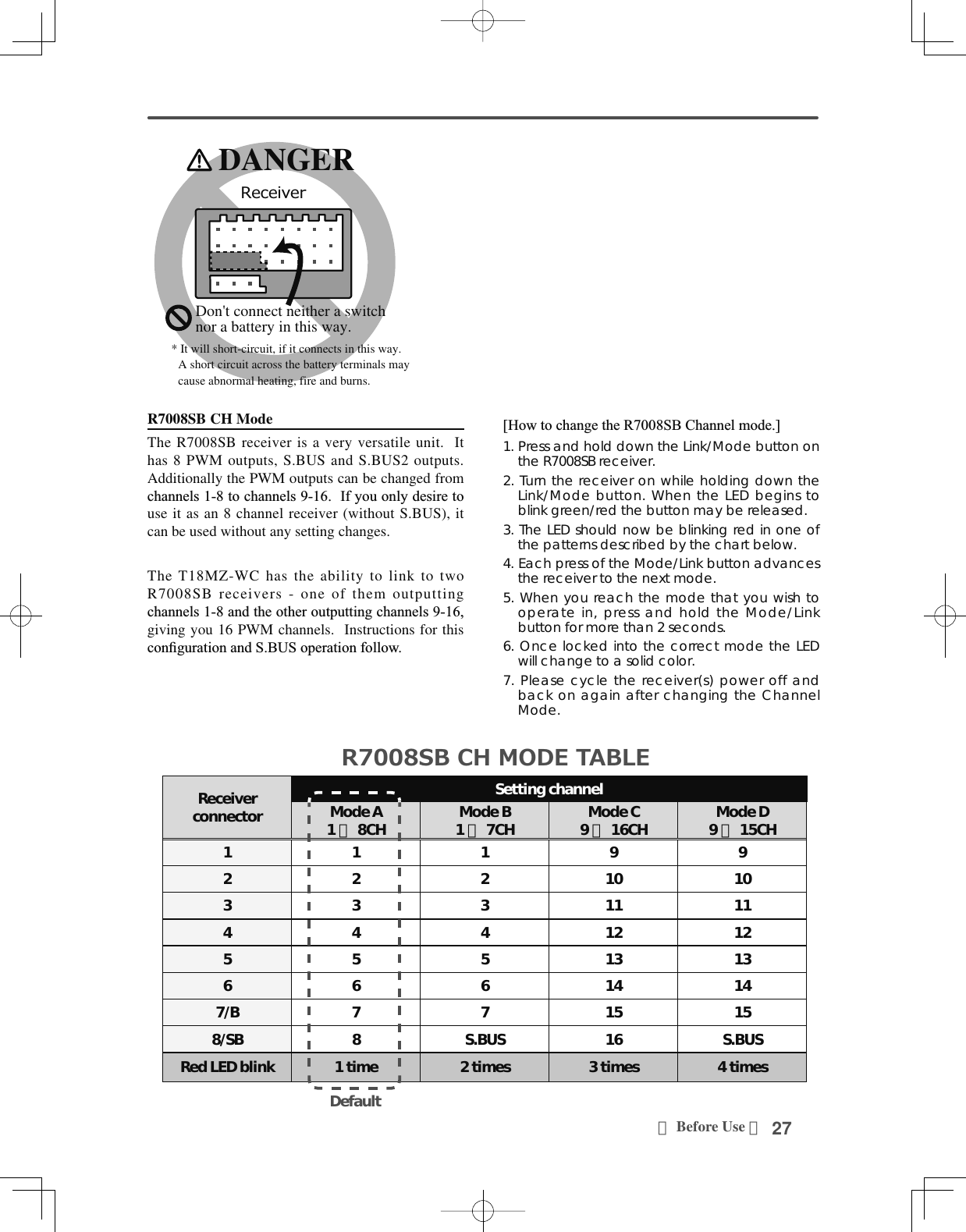
![25<Before Use >Link/Mode SwitchUse the small plastic screw driver that was included with your receiver. The Link/Mode Switch is also used for the CH mode selection. (The button is not used to link the transmitter and receiver together. )Extra Voltage ConnectorUse this connector when using a voltage telemetry device to send the battery voltage (DC0 ~ 70V) from the receiver to the transmitter. Please use an option is External voltage input cable. Wire in an extra connector to you drive batteries that mates with the extra voltage connector.DANGERDon't touch wiring. * There is a danger of receiving an electric shock.Do not short-circuit the battery terminals.* A short circuit across the battery terminals may cause DEQRUPDOKHDWLQJ¿UHDQGEXUQVPlease double check your polarity ( + and -) when hooking up your connectors. * If + and - of wiring are mistaken, it will damage, ignite and explode.'RQ¶WFRQQHFWLRQWR([WUD9ROWDJHEHIRUHturning on a receiver power supply.5HFHLYHUQRPHQFODWXUHBefore using the receiver, be sure to read the precautions listed in the following pages.Receiver R7008SBConnectorWKURXJKRXWSXWVIRUWKHFKDQQHOVWKURXJK%RXWSXWVRIFKDQQHOVDQGSRZHU6%RXWSXWVRIFKDQQHOVRU6%86SRUW[S.BUS Sevo S.BUS Gyro ]6%86RXWSXWVRI6%86SRUW[Telemetry Sensor ]:KHQXVLQJRUPRUHFKDQQHOVXVHDQ6%XVfunction or use a second R7008SB and link both to your transmitter.Connector insertion Firmly insert the connector in the direction shown LQWKH¿JXUH,QVHUWWKH6%86E\WXUQLQJLWdegrees.WARNINGS.BUS2 connectorsDon't connect an S.BUS servo / gyro to BUS2 connector.LED Monitor This monitor is used to check the CH mode of the receiver.Channels 1 ∼ 6 Channel 7 / BatteryChannel 8 or S.BUS S.BUS2 : Telemetry sensor or S.BUS2 equipment+−](https://usermanual.wiki/Futaba/T18MZWC-24G.User-Manual-1/User-Guide-2898093-Page-25.png)
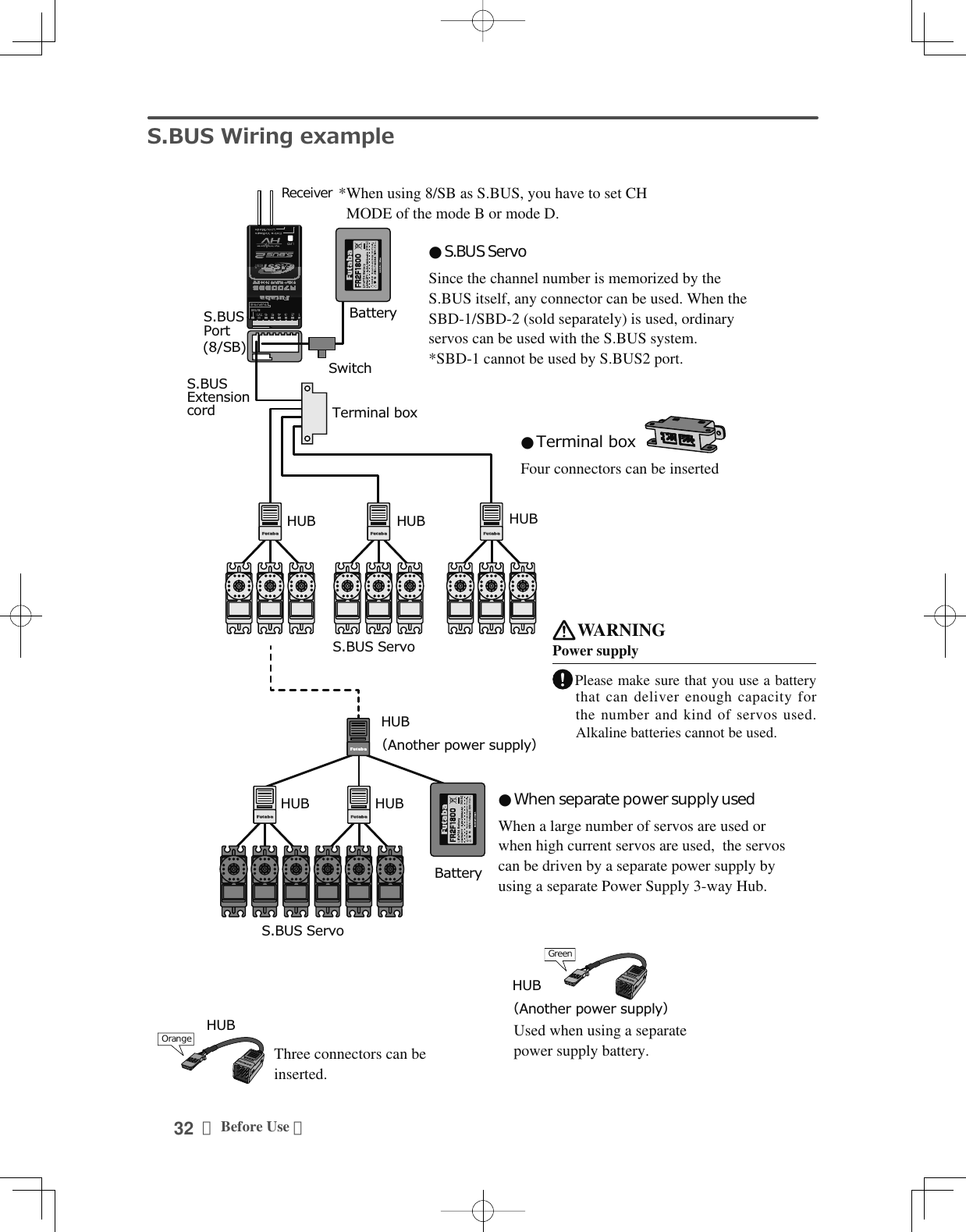
![31<Before Use >6%86,QVWDOODWLRQ7KLVVHWXVHVWKH6%86V\VWHP7KHZLULQJLVDVVLPSOL¿HGDQGFOHDQPRXQWLQJDVSRVVLEOHHYHQZLWKPRGHOVthat use a large number of servos. In addition, the wings can be quickly installed to the fuselage without any erroneous wiring by the use of only one simple wire, even when there are a large number of servos used.Ɣ:KHQXVLQJ6%86VSHFLDOVHWWLQJVDQGPL[HVLQ\RXUWUDQVPLWWHUPD\EHXQQHFHVVDU\Ɣ7KH6%86VHUYRVDQG6%86J\URVPHPRUL]HWKHQXPEHURIFKDQQHOVWKHPVHOYHV6HWWDEOHZLWKWKH70=WC)Ɣ7KH6%86V\VWHPDQGFRQYHQWLRQDOV\VWHPUHFHLYHUFRQYHQWLRQDO&+XVHGFDQEHPL[HGReceiver: R7008SBBattery: FR2F1800 ( Optional )Switch: ESW-1JThrottle servo: BLS173SV ( Optional )Aileron servo: BLS174SV×2 ( Optional )Elevator servo: BLS173SV×2 ( Optional )Rudder Servo: BLS175SV×1 ( Optional )HUB×3 ( Optional )HUB ( Optional ) S.BUS Glider usage exampleS.BUS Aerobatic plane usage example Receiver: R7008SBServo: S3173SVi×9(Optional )i-Connector ( Optional )](https://usermanual.wiki/Futaba/T18MZWC-24G.User-Manual-1/User-Guide-2898093-Page-31.png)
![35<Basic Operation >%$6,&23(5$7,21%DWWHU\&KDUJLQJBefore charging batteries, read the "Cautions for handling battery and battery charger" in the section "For your safety".Charging the transmitter LT2F3500XH lithium-polymer battery DANGER The LT2F3500XH lithium-polymer battery is for the T18MZ-WC transmitter only. Do not use it with other devices. Always use the included AC adapter to charge the battery.The charging circuit is built into the T18MZ-WC.[Method of charging battery]70=$&&KDUJHODPS1. Turn off the transmitter power.2. Connect the power plug of the AC adapter to an 110V outlet.*Don't connect AC plug to the T18MZ-WC without connecting with a 110V outlet.3. Open the back lid of the transmitter and insert the plug of the AC adapter into the CHG port.4. The charging monitor of the transmitter lights red.*In the case LCD screen will come on for several seconds and then go off. It may take several seconds for charging to start after the AC adapter is connected.5. When the battery is fully charged the transmitter monitor will light green. Remove the charge plug and AC adaptor.*After using the AC adapter always disconnect the power cord from the AC outlet.*The time to charge a completely discharged battery pack is approximately 2 hours 30 minutes. However, the actual charging time may vary depending on temperature and state of the battery.*If the battery is improperly installed or is faulty, the transmitter monitor will not light and the battery will not charge.How to charge the LiFe battery FR2F1800 (Option) for the receiverUse the battery charger that is included in the set.[Method of charging battery]$&3S2SMODEL :LBC-4E5Intelligent LiFePO4 for 2S/3S CellsBalance CHARGERRed on, green off : ChargingRed flash : Output short-circuit or wrong polarityGreen on, red off : Charging Fullٴ7KHFRQQHFWRURIWKHEDWWHU\LVFRQQHFWHGZLWK6VLGHRIWKHFKDUJHUق6VLGHVك&KDUJHU/%&(1. Connect the power cable of the charger to the wall socket (AC outlet).2. Connect the connector to the LiFe battery.*Confirm that the red LED charging indicator lights are on.3. Remove the battery after the LED light turns green.*After completing the charge remove the battery from the charger and remove the charger from the wall outlet.WARNINGThe transmitter battery cannot be charged with the receiver charger. Conversely the receiver battery cannot be charged with the transmitter charger.](https://usermanual.wiki/Futaba/T18MZWC-24G.User-Manual-1/User-Guide-2898093-Page-35.png)
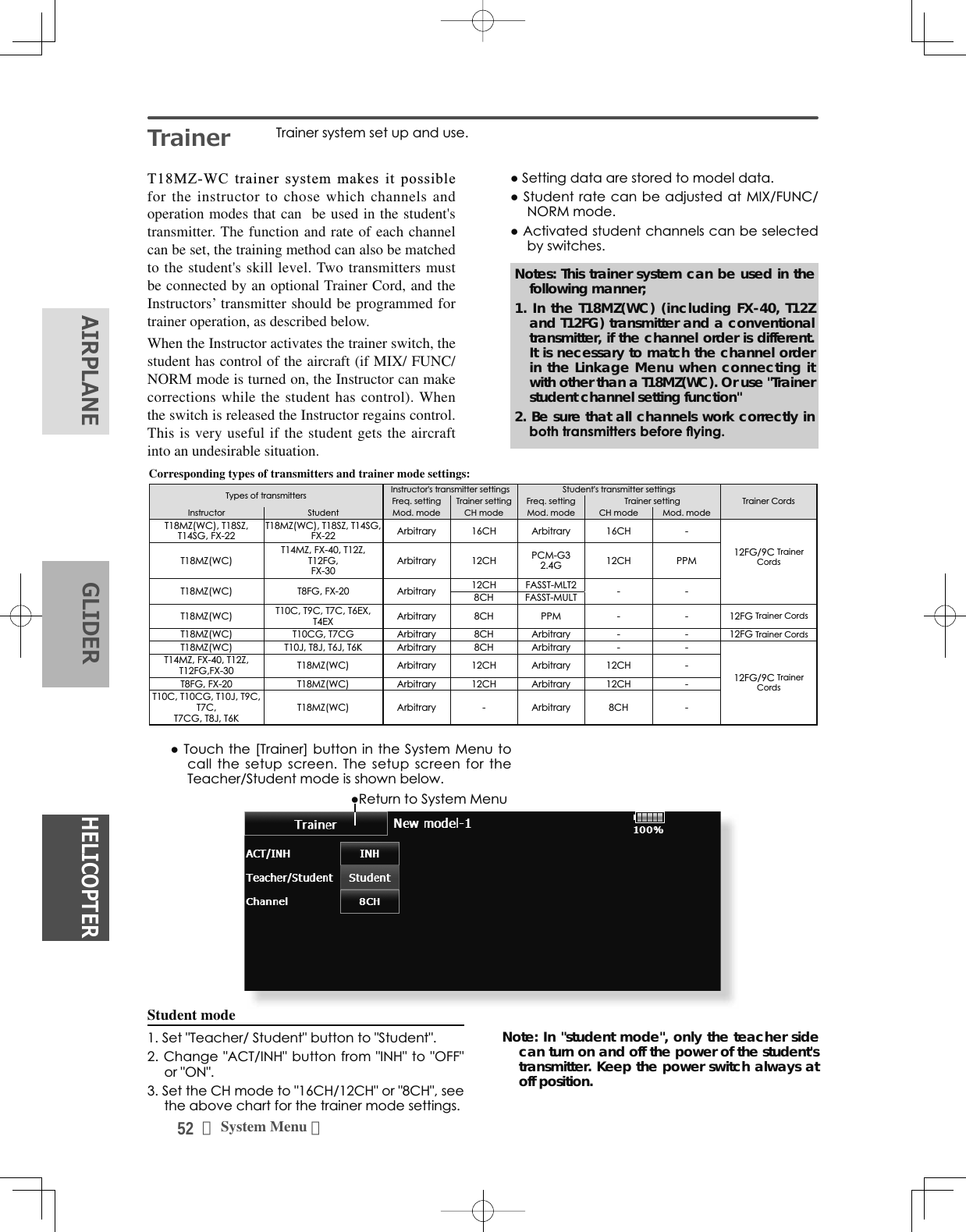
![39<Basic Operation >8VHU0HQXT18MZ-WC has a menu for each of the following: System, Linkage, and Model. Also, you can create a personalized User Menu that can include all of the menus that you use most often. The User menu can be created by pressing the Rotary Key. How to make a User Menu1. From the home screen, press the Rotary key for 2 seconds.7RXFKKHUHWRVHOHFW\RXUÀUVWFKRLFH3. Once pressed, 4 pages of choices will be displayed.4. Make your selection, press your choice and the first of your "User Menu" will be entered.ŏ5HWXUQWRKRPHVFUHHQŏ5HWXUQWRKRPHVFUHHQŏ5HWXUQWRKRPHVFUHHQŏ5HWXUQWR8VHU0HQXŏ7RHUDVHDVHOHFWLRQIURP\RXU8VHU0HQXKLJKOLJKWWKHGHVLUHGmenu and press Release. This will remove it from your personal User Menu, but not from the basic menu. You can always go back at a later date and re-enter this into your User Menu.ŏ7KUHHWHOHPHWU\GDWDVFUHHQVFDQEHGLVSOD\HGIf three either is pushed, it will move to a telemetry screen. Three displays can be changed on a telemetry screen.*Any change made to data entered from the User Menu or from the normal method of use are the same. Changes made in either way are saved into the transmitter memory. +RPHVFUHHQIf [Home2] is pushed, it will become the display to which the timer and the Telemetry data were expanded.TimerIf one of two timer displays is pushed, you will enter the Timer screen of a Linkage menu.](https://usermanual.wiki/Futaba/T18MZWC-24G.User-Manual-1/User-Guide-2898093-Page-39.png)
![44 <Model Basic Setting Procedure >&RQÀUPWKDWWKHUDWHRIWKHVORZHVWSRVLWLRQRIWKHVWLFNLVLQLWLDOVHWWLQJ%HVXUHWKDWZKHQVHWWRKLJKVLGHWKHFXUYHRIDQ\FRQGLWLRQGRHVQRWH[FHHGExample of pitch curve setting:1. Call the pitch curve of each condition with the condition select switch.*Pitch curve graph display can be switched to pitch angle direct reading display.$3LWFKFXUYH1RUPDOMake the pitch at hovering approximately +5º~6º.Set the pitch at hovering with the stick position at WKHSRLQWDVWKHVWDQGDUG*Stability at hovering may be connected to the throttle curve. Adjustment is easy by using the hovering throttle function and hovering pitch function together.%3LWFKFXUYH,GOHXSThe idle up 1 pitch curve function creates a curve PDWFKHGWRDLUERUQHÁLJKWSet to -7ºaº as standard.&3LWFKFXUYH,GOHXSThe high side pitch setting is less than idle up 1. The standard is +8º.D. Pitch curve (Hold)$WDXWRURWDWLRQXVHWKHPD[LPXPSLWFKDWERWKthe high and low sides.[Pitch angle setting example]7KURWWOHKROGºaº6. Throttle hold settingCall the Throttle Hold function from the Model Menu and switch to the throttle hold condition with the condition select switch.Note: $WLQLWLDOVHWWLQJWKHVHWWLQJPRGHLVWKHgroup mode. Since this function is not used at other conditions, switch to the single mode before setting.ŏ6HWWLQJWRWKHVWDWHZKLFKDFWLYDWHVWKHIXQFWLRQThe throttle hold function allows setting for throttle cut DQGVZLWFKLQJRIWKHIXQFWLRQÀ[HGDWWKHLGOHSRVLWLRQby switch for training. Either one or both functions can be performed.ŏ+ROGSRVLWLRQVHWWLQJThis function sets the servo operation position at throttle hold. (Throttle cut and idle positions)ŏ2WKHUVHWWLQJVWhen you want to link operation with stick PDQLSXODWLRQWKH$XWRPRGHFDQEHVHWWhen you want to adjust the servo speed, adjust [Speed].3LWFKWR58'PL[LQJVHWWLQJUse this function when you want to suppress the torque generated by the changes in the pitch and speed of the main rotor during pitch operation. Adjust it so that the nose does not swing in the rudder direction. However, when using a heading hold gyro like those shown below, do not use Pitch to RUD mixing.Note:KHQXVLQJD)XWDED*<VHULHVJ\URRURWKHUKHDGLQJKROGJ\URWKLV3LWFKWR58'PL[LQJVKRXOGnot be used. The reaction torque is corrected at WKHJ\URVLGH:KHQRSHUDWLQJWKHJ\URLQWKH$9&6mode, the mixed signal will cause neutral deviation symptoms and the gyro will not operate normally.Call the Pitch to RUD mixing function from the Model Menu, and set the curve for each condition. (At initial setting, this function is in the "INH" state. To use it, set it to the "ON" state.)(17 points curve)Curve setting of up to 17 points is possible. However, in the following setting example, a simple curve can be adjusted by using the [Linear] curve type.Note:$WLQLWLDOVHWWLQJWKHVHWWLQJPRGHLVWKHJURXSPRGH,QWKLVPRGHWKHVDPHFRQWHQWVDUHVHWDWLQall conditions. When you want to set the selected condition only, switch to the single mode.6HWWLQJH[DPSOH!Call the mixing curve of each condition with the condition select switch.The throttle hold curve is used when performing auto rotation dives.](https://usermanual.wiki/Futaba/T18MZWC-24G.User-Manual-1/User-Guide-2898093-Page-44.png)
![45<Model Basic Setting Procedure >$FXUYHVHWWLQJH[DPSOHLVVKRZQEHORZ$3LWFKWR58'PL[LQJFXUYH1RUPDO8VHWKHKRYHULQJV\VWHPDQGVHWWKLVFXUYHWRmatch take off and landing and vertical climb at a constant speed.*For this curve, use the initial setting [Linear] curve type and adjust the left and right rates in the [Separate] mode.%3LWFKWR58'PL[LQJ,GOHXS8VHWKLVFXUYHLQVWDOOWXUQORRSDQGDGMXVWLWVRWKHfuselage is facing straight ahead when heading into the wind.*For this curve, [Linear] curve type can be used and the entire curve can be lowered with the [Offset] button.&3LWFKWR58'PL[LQJ+ROGThis function is set so that the fuselage is facingstraight ahead during straight line auto rotation. The SLWFKRIWKHWDLOURWRUEHFRPHVQHDUO\*For this curve, [Linear] curve type can be used and the entire curve can be lowered with the [Offset] button.ŏ2WKHUVHWWLQJVThe mixing rise characteristic of pitch operation can EHDGMXVWHG$QDFFHOHUDWLRQ$&/5IXQFWLRQZKLFKtemporarily increases and decreases themixing amount, can be set.6ZDVK0L[FRUUHFWVDLOHURQHOHYDWRUDQGSLWFKinteractionThe swash mix function is used to correct the swash plate in the aileron (roll) direction and elevator (cyclic pitch) corresponding to each operation of each condition.7KURWWOHPL[LQJVHWWLQJRPM loss caused by swash operation of aileron or elevator can be corrected with the Throttle Mix function in the Model Menu. The effects of clockwise and counterclockwise torque applied when pirouetting can also be corrected.10. Gyro sensitivity and mode switchingThe gyro sensitivity and mode switching function is dedicated to gyro mixing for each model used, and can be set for each condition.ŏ1RUPDOFRQGLWLRQKRYHULQJ*\URVHQVLWLYLW\maximumŏ,GOHXS,GOHXS7KURWWOHKROG*\URVHQVLWLYLW\minimumŏ+RZHYHUDWDXWRURWDWLRQRIDWDLOGULYHQhelicopter, this function may not have any affect at high gyro sensitivity.11. Throttle cut settingThrottle cut provides an easy way to stop the HQJLQHE\ÀLSSLQJDVZLWFKZLWKWKHWKURWWOHVWLFNDWidle. The action is not functional at high throttle to avoid accidental dead sticks. The switch’s location and direction must be chosen, as it defaults to NULL.*With throttle stick at idle, adjust the cut position until the engine consistently shuts off, but throttle linkage is not binding. When finished, touch the “Throttle Cut” button to exit.2WKHUVSHFLDOPL[LQJVŏ3LWFKWR1HHGOHPL[LQJThis mixing is used with engines with a construction ZKLFKDOORZVQHHGOHFRQWUROGXULQJÁLJKWIXHODLUPL[WXUHDGMXVWPHQW$QHHGOHFXUYHFDQEHset. The needle servo rise characteristics at throttle stick acceleration/deceleration operation can be DGMXVWHG$FFHOHUDWLRQIXQFWLRQŏ)XHOPL[WXUHIXQFWLRQThis mixing is used in needle adjustment of engines which use a fuel mixture control carburetor.ŏ*RYHUQRUPL[LQJThis mixing is dedicated governor mixing when a JRYHUQRULVXVHG8SWRUDWHVVSHHGVFDQEHswitched for each condition.](https://usermanual.wiki/Futaba/T18MZWC-24G.User-Manual-1/User-Guide-2898093-Page-45.png)
![55<System Menu >+(/,&237(5$,53/$1(*/,'(5Auto power off time setting7KHIXQFWLRQWRSUHYHQWDEDWWHU\IURPGLVFKDUJLQJE\IDLOXUHRIWKHSRZHUVXSSO\RIDWUDQVPLWWHUWRHUDVH$GMXVWWKHDXWRSRZHURIIWLPHZLWKWKHOHIWDQGULJKWVLGHEXWWRQV:KHQWKHWLPHWKHWUDQVPLWWHULVLQDFWLYHUHDFKHVWKHVHWWLPHWKHSRZHULVWXUQHGRIIDXWRPDWLFDOO\7KLVWLPHFDQEHVHWXSWRKRXULQPLQXWHVLQFUHPHQWV7KHDXWRSRZHU RIIIXQFWLRQFDQDOVREHGHDFWLYDWHG$QDXGLEOHDODUPLVVRXQGHGDQGDQDODUPVFUHHQLVGLVSOD\HGIURP PLQXWHVEHIRUHDXWRSRZHURIIDQGWKHWLPH UHPDLQLQJXQWLODXWRSRZHURIILVGLVSOD\HG:KHQDVWLFNRUVZLWFKLVRSHUDWHGZKLOHWKHDODUPVFUHHQLVEHLQJGLVSOD\HGWKHDODUPLVFOHDUHGDQGWKHGLVSOD\LVUHWXUQHGWRWKHKRPHVFUHHQBacklighting brightness adjustment$GMXVWWKHEDFNOLJKWLQJEULJKWQHVVZLWKWKHOHIWDQGULJKWVLGHEXWWRQV:KHQWKHULJKWVLGHEXWWRQLVWRXFKHGWKHEDFNOLJKWLQJEHFRPHVEULJKWHU:KHQ WKHOHIWVLGHEXWWRQLVWRXFKHG WKHEDFNOLJKWLQJEHFRPHVGDUNHUBacklight decrease brightness adjustment$GMXVWWKHEDFNOLJKWGHFUHDVHEULJKWQHVVZLWKWKHOHIWDQGULJKWVLGHEXWWRQV:KHQWKHULJKWVLGHEXWWRQLVWRXFKHGWKHEDFNOLJKWLQJEHFRPHVEULJKWHU:KHQ WKHOHIWVLGHEXWWRQLVWRXFKHG WKHEDFNOLJKWLQJEHFRPHVGDUNHU,WFDQQRWEHPDGHEULJKWHUWKDQ%DFNOLJKWLQJEULJKWQHVVDGMXVWPHQW'LVSOD\ /&'VFUHHQDGMXVWPHQWDQGDXWRSRZHURIIVHWWLQJThe following LCD screen adjustments and auto power off setting are possible:ŏ$XWRSRZHURIIWLPHVHWWLQJŏ%DFNOLJKWLQJEULJKWQHVVDGMXVWPHQWŏ%DFNJURXQGFRORUFKDQJHŏ7RXFKSDQHOVFUHHQFDOLEUDWLRQDQGWRXFKSDQHOORFNFRUUHFWLRQŏ7RXFKWKH>'LVSOD\@EXWWRQLQWKH6\VWHP0HQXWRFDOOWKHVHWXSVFUHHQVKRZQEHORZŏ5HWXUQWR6\VWHP0HQXBacklight decrease time<RXFDQVHWD WLPHSHULRGWRGHFUHDVHWKH/&'EDFNOLJKW7KLVIXQFWLRQFRXQWV WKHSHULRGWKDWWKHWRXFKSDQHOKDVQRW EHHQRSHUDWHG7KLVWLPHFDQEHVHWE\WHQVHFRQGVWHSV<RXFDQDOVRWXUQRIIWKHEDFNOLJKWGHFUHDVHLI\RXOLNH7KHEDFNOLJKWFRQVXPHVD ODUJHDPRXQWRISRZHU:HUHFRPPHQG\RXWR WXUQRIIWKHEDFNOLJKWE\VHWWLQJWKHEDFNOLJKWSRZHURII WLPHWRDERXWRQHPLQXWHBackground color7RXFKWKHEXWWRQRIWKHFRORU\RXZDQWWRFKDQJH7KHUHDUHÀYHEDFNJURXQGFRORUVTouch screen[Start-up lock],1+ ⇒21LWLVWRXFKSDQHOORFNHGZKHQHYHULWWXUQVRQWKHSRZHUVXSSO\RI70=:&,WZLOOEHFDQFHOHGLI6DQG6NH\DUHSXVKHGVLPXOWDQHRXVO\[Automatic lock],1+ ⇒21,WV\QFKURQL]HVZLWK%DFNOLJKWGHFUHDVHWLPHDQG EHFRPHVDSDQHOORFN,WZLOOEHFDQFHOHGLI6DQG6NH\DUHSXVKHGVLPXOWDQHRXVO\[Cal.]calibration7KLVIXQFWLRQDGMXVWVWKHORFDWLRQRIWRXFKSDQHO7RXFK &DOLEUDWLRQEXWWRQDQGWKHQSUHVV<HVWKHFDOLEUDWLRQVFUHHQZLOOSRSXS7RXFKWKHFHQWHURIWKHFURVVKDLUFXUVRURQWKHVFUHHQZLWKWKHVW\OXVSHQ$V VRRQDVWKHV\VWHPUHFRJQL]HV WKHSRVLWLRQWKHFXUVRUZLOOPRYHRQWRWKHQH[WSRVLWLRQ5HSHDWWKLVSURFHGXUHDV ORQJDVWKHFXUVRUPRYHVWRQH[WSRVLWLRQ<RXZLOOGRWKLVÀYHWLPHV&DOLEUDWLRQZLOOEHFDUULHGRXW EDVHGRQWKHILYHSRVLWLRQV'LVDSSHDUDQFHRIWKHFURVV KDLUFXUVRUPHDQVWKHFDOLEUDWLRQKDVEHHQFRPSOHWHG7RXFKDQ\SRLQWRQWKHVFUHHQWRUHWXUQWRWKHSUHYLRXVVFUHHQ,QRUGLQDU\RSHUDWLRQWKLV FDOLEUDWLRQLVQRWQHFHVVDU\,I\RXQRWLFH WKHWRXFKSDQHOLVQRWIXQFWLRQLQJFRUUHFWO\DIWHUORQJXVHZHUHFRPPHQG\RXFDUU\RXWWKLVFDOLEUDWLRQ](https://usermanual.wiki/Futaba/T18MZWC-24G.User-Manual-1/User-Guide-2898093-Page-55.png)
![58 <System Menu >+(/,&237(5$,53/$1( */,'(5Switch selection6HOHFWWKHVZLWFKW\SHE\WRXFKLQJWKH>7\SH@EXWWRQFRUUHVSRQGLQJWRWKHVZLWFKWREHUHSODFHG >/HYHU@7RJJOHVZLWFK >%XWWRQ@3XVKEXWWRQ >'LDO@.QREŏ6HWWLQJIRUWRJJOHVZLWFKLVVKRZQDERYH2/3 position selection7RXFKWKH3RVLEXWWRQFRUUHVSRQGLQJWRWKHVZLWFKDQGVHOHFWWKHSRVLWLRQW\SH >3RVL@SRVLWLRQ >3RVL@SRVLWLRQ7RJJOHVZLWFKW\SHVHWWLQJ6HWWLQJZKHQWKHVZLWFKZDVUHSODFHGIf you modify the location of the switches on the right and left (top) of the transmitter, you should be VXUHWRUHDVVLJQIXQFWLRQVWRWKHVZLWFKHVIRUSURSHUoperation.A “Lock” is included to prevent settings from being modified by mistake. When you need to change settings, unlock this by pressing “Lock”. It will then read “Unlock” and you can make changes as required.ŏ7RXFKWKH>6ZLWFK@ EXWWRQLQWKH6\VWHP0HQXWRFDOOXSWKHVHWXSVFUHHQVKRZQEHORZŏ5HWXUQWR6\VWHP0HQX[Alt/Mom] mode selection6HOHFWWKHRSHUDWLRQPRGHE\WRXFKLQJWKH>$OW0RP@EXWWRQFRUUHVSRQGLQJWRWKHVZLWFK >$OW@$OWHUQDWHW\SH >0RP@6HOIUHWXUQW\SHŏ6HOHFWLRQRIWKH>0RP@PRGHZLWKDSRVLWLRQW\SHVZLWFKLVVKRZQDERYH"3P Mom" mode selection6HOHFWWKHRSHUDWLRQPRGHE\WRXFKLQJWKH30RPEXWWRQFRUUHVSRQGLQJWRWKHVZLWFK >6LQJOH@2QHVLGHVHOIUHWXUQW\SH >'XDO@%RWKGLUHFWLRQVVHOIUHWXUQW\SH6ZLWFK](https://usermanual.wiki/Futaba/T18MZWC-24G.User-Manual-1/User-Guide-2898093-Page-58.png)
![62 <System Menu >+(/,&237(5$,53/$1( */,'(5Copy / Delete / Rename'DWDLVFKRVHQIURP3OD\EDFN)LOH6HOHFWGDWDÀOH&RS\'HOHWHRU5HQDPHWKHÀOH6HOHFW><HV@RU>1R@WRHLWKHUFRQÀUPRUGHQ\WKHFKDQJHV\RXZLVKWRGR0XVLFSOD\EDFN7KH70=:&WUDQVPLWWHUFDQSOD\EDFNZPDPXVLF¿OHVVWRUHGLQ\RXU6'FDUGDQG86%PHPRU\<RXFDQOLVWHQWRWKHPWKURXJKWKHEXLOWLQVSHDNHUor through the headphone jack with your own headphones.[Important notice]%HIRUHGRZQORDGLQJ¿OHVIURP\RXU3&LQWRWKHSD card, insert the SD card into the transmitter and turn on the power of the transmitter. Then the following folders will be automatically FUHDWHGLQWKH6'FDUG:KHQ\RXGRZQORDG¿OHVIURP\RX3&FRS\DQGSDVWHWKH¿OHVLQWRWKHLUFRUUHVSRQGLQJ¿OHV%03SLFWXUHÀOHV:0$PXVLFÀOHV:$9VRXQGÀOHV02'(/PRGHOGDWDÀOHV3XVKWKH0XVLF3OD\EDFNEXWWRQRQWKHKRPHVFUHHQWRFDOOWKHIROORZLQJVHWXSVFUHHQ5HWXUQWRWKHKRPHVFUHHQ %XWWRQWRVHOHFWHLWKHU2QHWLPH3OD\EDFNRU5HSHDW3OD\EDFN%XWWRQWRVHOHFWHLWKHU2QH0XVLF3OD\EDFNRU0XOWLSOH0XVLF3OD\EDFN6:VHOHFWLRQEXWWRQ3XVKWKLVEXWWRQWRFDOOWKH6:VHOHFWVFUHHQDQGFKRRVHWKH0XVLFSOD\EDFNVZLWFK5HIHUWRWKHGHVFULSWLRQLQWKHHQGRIWKLVPDQXDOButtons for music playback<RXFDQSOD\EDFNDQ\PXVLFÀOHVOLVWHGRQWKHULJKWVLGHRIWKHVFUHHQ,I\RXDGMXVWWKHYROXPHKHUHLWDGMXVWVQRWRQO\PXVLFSOD\EDFNEXWDOVRRWKHUDSSOLFDWLRQV To playback$OOWKHPXVLFÀOHVVDYHGLQWKH70=:&6'FDUG86%PHPRU\ZLOOEHVKRZQKHUH3XVKWKHILOHQDPHWRVHOHFWWKHPXVLFILOH\RXZDQWWRKHDU8VHWKHEXWWRQVRQ WKHOHIWWRSOD\EDFNRUVWRSWKHPXVLF3OD\EDFNÀOHOLVW3OD\HU](https://usermanual.wiki/Futaba/T18MZWC-24G.User-Manual-1/User-Guide-2898093-Page-62.png)
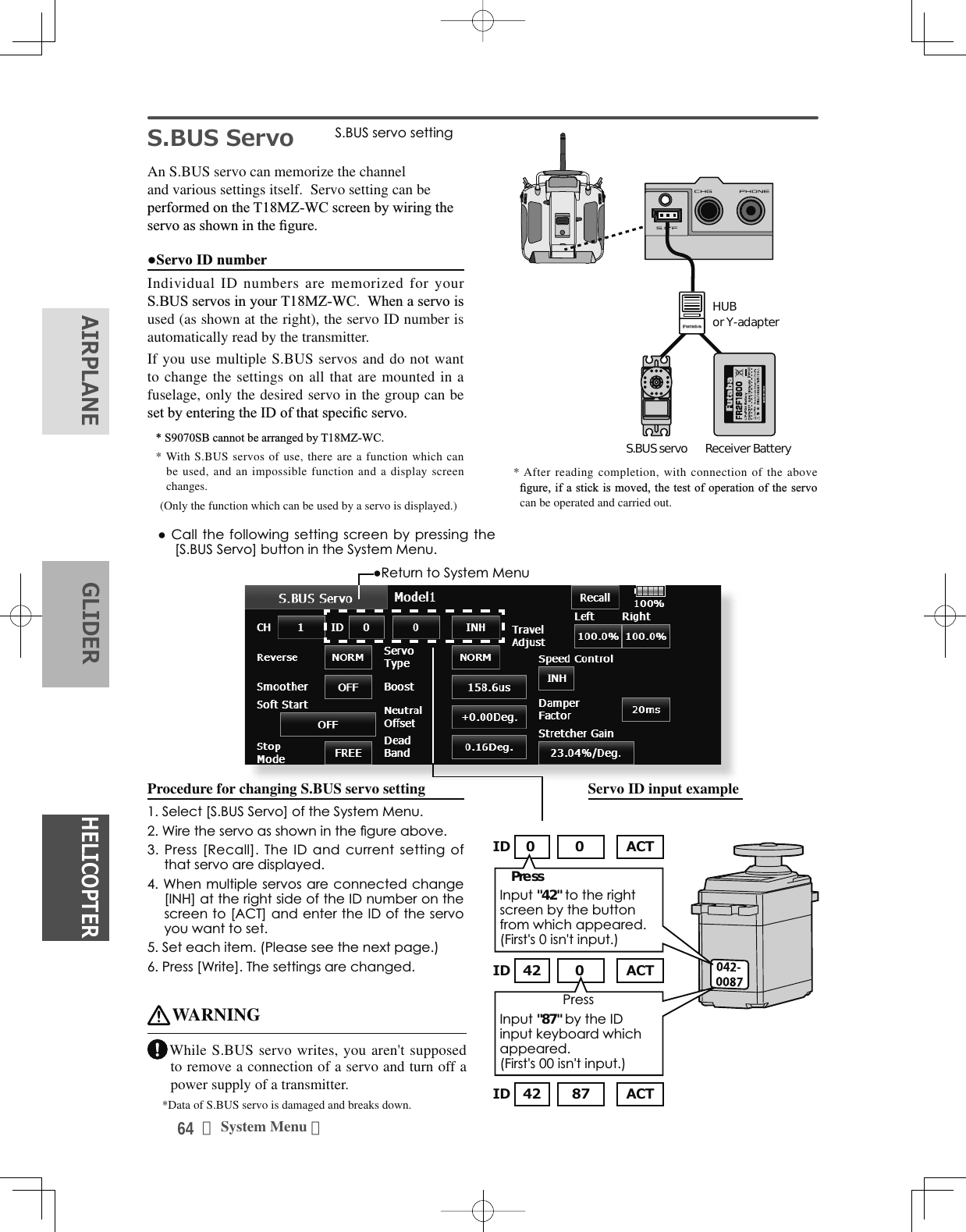
![65<System Menu >+(/,&237(5$,53/$1(*/,'(5S.BUS Servo Description of function of each parameter*There are functions which can be used according to the kind of servo, and an impossible function. • IDDisplays the ID of the servo whose parameters are to be read. It cannot be changed.• ChannelChannel of the S.BUS system assigned to the servo. Always assign a channel before use.• ReverseThe direction in which the servo rotates can be changed.• Servo type■Normal: Normal operation mode■Retract: Landing gear retract mode. When a load is applied to the servo for 30 seconds without any channel operation performed from the transmitter, the current consumption is suppressed by widening the dead band to 40°. When channel operation is performed from the transmitter, or the servo is moved outside the expanded dead band by an outside force, dead band expansion is reset and returns to the original operation.■O.L.P. : This is the Over Load Protection mode. When a servo horn has been locked for more than 5 seconds by a load, the servo output turns off to protect the servo.* The normal mode and retract mode are applicable only to the S3171SB, S9071SB, S9072SB, S9074SB, and S9075SB• Soft StartRestricts operation in the specified direction the instant the power is turned on. By using this setting, the first initial movement when the power is turned on slowly moves the servo to the specified position.• Stop Mode The state of the servo when the servo input signal is lost can be specified. The "Hold" mode setting holds the servo in its last commanded position even if using AM or FM system.• SmootherThis function changes smoothness of the servo operation relative to stick movement changes. Smooth setting is used for normal flight. Select the "OFF" mode when quick operation is necessary such as 3D.• Neutral OffsetThe neutral position can be changed. When the neutral offset is large value, the servo's range of travel is restricted on one side.• Speed ControlSpeeds can be matched by specifying the operating speed. The speed of multiple servos can be matched without being affected by motor fluctuations. This is effective for load torques below the maximum torque.However, note that the maximum speed will not exceed what the servo is capable of even if the servos operating voltage is increased. • Dead bandThe dead band angle at stopping can be specified.[Relationship between dead band set value and servo operation]Small ĺ Dead band angle is small and the servo is immediately operated by a small signal change.Large ĺ Dead band angle is large and the servo does not operate at small signal changes.(Note) If the dead band angle is too small, the servo will operate continuously and the current consumption will increase and the life of the servo will be shortened.• Travel AdjustThe left and right travels centered about the neutral position can be set independently.](https://usermanual.wiki/Futaba/T18MZWC-24G.User-Manual-1/User-Guide-2898093-Page-65.png)
![66 <System Menu >+(/,&237(5$,53/$1( */,'(5• BoostThe minimum current applied to the internal motor when starting the servo can be set. Since a small travel does not start the motor, it essentially feels like the dead band was expanded. The motor can be immediately started by adjusting the minimum current which can start the motor.[Relationship between boost set value and servo operation]Small ĺ Motor reacts to a minute current and operation becomes smooth.Large ĺ Initial response improves and output torque increases. However, if the torque is too large, operation will become rough.• Boost ON/OFFOFF : It is the boost ON at the time of low-speed operation.(In the case of usual)ON : It is always the boost ON.(When quick operation is hope)• DamperThe characteristic when the servo is stopped can be set.When smaller than the standard value, the characteristic becomes an overshoot characteristic. If the value is larger than the standard value, the brake is applied before the stop position.Especially, when a large load is applied, overshoot, etc. are suppressed by inertia and hunting may occur, depending on the conditions. If hunting (phenomena which cause the servo to oscillate) occurs even though the Dead Band, Stretcher, Boost and other parameters are suitable, adjust this parameter to a value larger than the initial value.[Relationship between damper set value and servo operation]Small ĺ When you want to overshoot. Set so that hunting does not occur.Large ĺ When you want to operate so that braking is not applied. However, it will feel like the servo response has worsened.(Note) If used in the hunting state, not only will the current consumption increase, but the life of the servo will also be shortened.• StretcherThe servo hold characteristic can be set. The torque which attempts to return the servo to the target position when the current servo position has deviated from the target position can be adjusted.This is used when stopping hunting, etc., but the holding characteristic changes as shown below.[Relationship between stretcher and servo operation]Small ĺ Servo holding force becomes weaker.Large ĺ Servo holding force becomes stronger.(Note) When this parameter is large, the current consumption increases.• BuzzerWhen the power supply of a servo is previously turned on at the time of a power supply injection without taking transmit of a transmitter, the buzzer sound of about 2.5 Hz continues sounding from a servo. (Even when the transmit of a transmitter is taken out previously, a buzzer sounds until the signal of a servo is outputted normally, but it is not unusual.) The transmitter has been turned OFF ahead of a servo power supply → The buzzer sound of about 1.25 Hz continues sounding as servo power supply end failure alarm.(Do not insert or remove the servo connector while the receiver power is ON. A buzzer may sound by incorrect recognition.) *Buzzer sound is generated by vibrating the motor of a servo. Since current is consumed and a servo generates heat, please do not operate the number more than needed or do not continue sounding a buzzer for a long time.](https://usermanual.wiki/Futaba/T18MZWC-24G.User-Manual-1/User-Guide-2898093-Page-66.png)
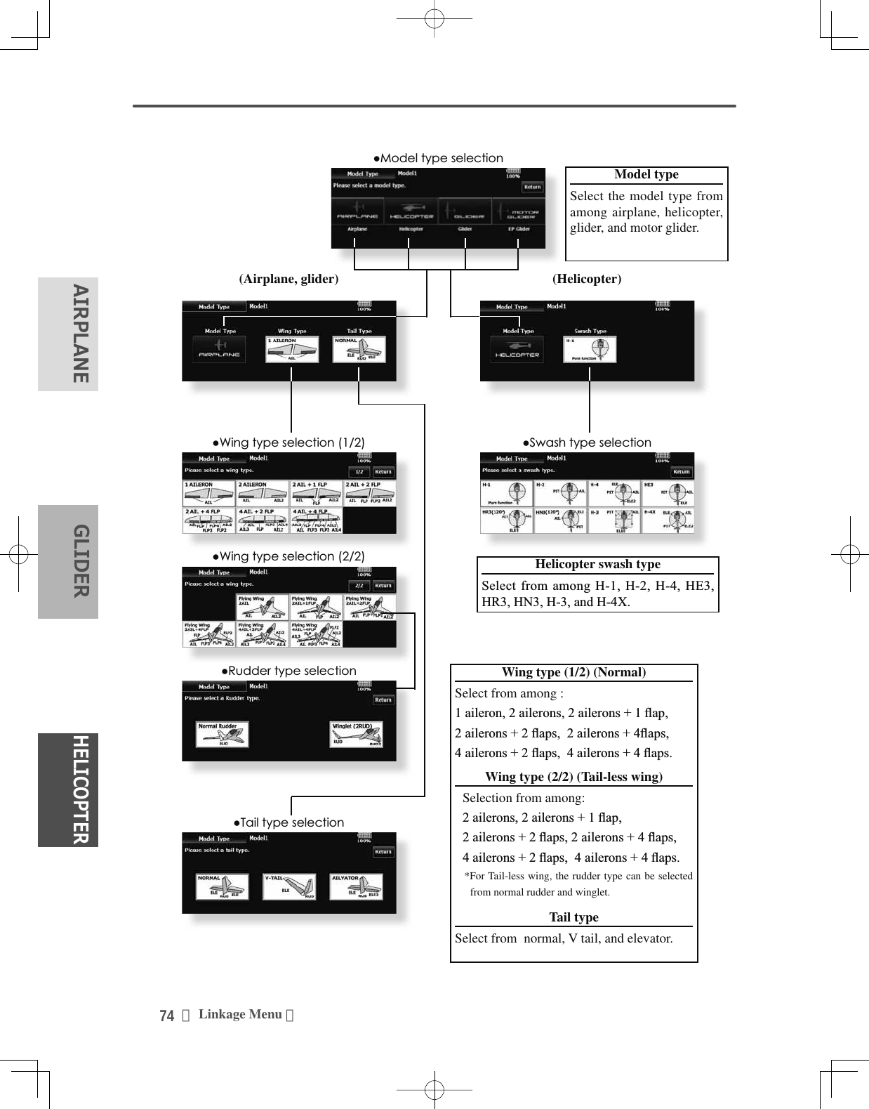
![73<Linkage Menu >+(/,&237(5$,53/$1(*/,'(5ŏ5HWXUQWR/LQNDJH0HQXŏ7RXFKWKH>0RGHO7\SH@EXWWRQLQWKH/LQNDJH0HQXWRFDOOWKHVHWXSVFUHHQVKRZQEHORZŏ:KHQDGDWDFKDQJHZLOORFFXUWKHFRQÀUPDWLRQVFUHHQRIGDWDLQLWLDOL]DWLRQPHQXZLOOEHGLVSOD\HG$SXVKRQ>\HV@ZLOOLQLWLDOL]HGDWDDQGDOORZFKDQJHV$SXVKRQ>QR@ZLOOVWRSGDWDFKDQJHV0RGHO7\SH 7KLVIXQFWLRQDOORZV\RXWRVHOHFWWKHPRGHOW\SHIURPDPRQJDLUSODQHKHOLFRSWHUDQGJOLGHU7KHGLVSOD\VFUHHQLVDQH[DPSOH7KHVFUHHQGHSHQGVRQWKHPRGHOW\SHSeven types of main wings and three types of tail wings are available for airplanes. Eight swash types are available for helicopters. Seven types of main wings and three types of tail wings are available for JOLGHUV)XQFWLRQVDQGPL[LQJQHFHVVDU\IRUHDFKmodel type are set in advance at the factory.Note: 7KH0RGHO7\SHIXQFWLRQ DXWRPDWLFDOO\VHOHFWVWKHRSWLPDORXWSXWFKDQQHOVFRQWUROIXQFWLRQVDQGPL[LQJIXQFWLRQVIRUWKHFKRVHQPRGHOW\SH:KHQWKH0RGHO7\SH6HOHFWLRQLVDFFHVVHGDOORIVHWWLQJVLQWKHDFWLYHPRGHODUHFOHDUHG%HVXUHWKDW\RXGRQ·WPLQGORVLQJWKLVGDWDRU EDFNLWXSWRPHPRU\XVLQJWKHFRS\LQJIXQFWLRQVModel type selection6HWWKH0RGHOW\SH:LQJW\SH7DLOW\SHRU6ZDVKW\SHE\XVLQJWKHDSSURSULDWHEXWWRQ6HWWKHW\SH\RXFKRRVHE\WRXFKLQJ><HV@DWWKHFRQILUPDWLRQVFUHHQ:KHQ\RXZDQWWRFDQFHOPRGHOW\SHVHOHFWLRQWRXFK>1R@Date changes after a swash type change 'DWDWKDWKDVEHHQVHWPD\FKDQJHLIWKHVZDVKW\SHRI\RXUKHOLFRSWHULVFKDQJHG5HIHUWRWKHIROORZLQJWDEOH:KHQGDWDLVFKDQJHGWKH>VZDVKVHWWLQJ@VFUHHQLVLQLWLDOL]HGBefore After Data taking overH-1, H-2, HE3,HR3, HN3, H-3 H-1, H-2, HE3,HR3, HN3, H-3 OK++; ++; OKH-1, H-2, HE3,HR3, HN3, H-3 ++; NG++; H-1, H-2, HE3,HR3, HN3, H-3 NG73<LikM>](https://usermanual.wiki/Futaba/T18MZWC-24G.User-Manual-1/User-Guide-2898093-Page-73.png)
![75<Linkage Menu >+(/,&237(5$,53/$1(*/,'(5ŏ5HWXUQWR/LQNDJH0HQXŏ7RXFKWKH>3LFWXUH@EXWWRQLQWKH/LQNDJH0HQXWRFDOOWKHVHWXSVFUHHQVKRZQEHORZ3LFWXUH $SLFWXUHRQWKHKRPHVFUHHQFDQEHVHWIRUHDFKPRGHO6LPSOLILHVLGHQWLÀFDWLRQRIWKHPRGHOGDWDGXULQJVFUHHQRSHUDWLRQA photograph of the model taken with a T18MZ-WC camera, digital camera or other file can be pasted as the screen display data for each model. This is convenient in identifying models with the same model name.7KHSLFWXUH¿OHVZKLFKFDQEHGLVSOD\HGRQWKHVFUHHQDUHVL]H[SL[HOVILOHW\SHEPSELWPDSSLFWXUHDQG-3(*¿OHV,ID¿OHODUJHUWKDQ[LVXVHGWKHSLFWXUHGLVSOD\HGZLOOEHUHGXFHG$ODUJHU¿OHWKDQ[SL[HOVFDQQRWEHused.When a picture is pasted, it is displayed as a screen image in the following screens:ŏ0RGHO6HOHFWVFUHHQŏ+RPHVFUHHQŏ6WDUWXSVFUHHQPasting a picture3LFWXUHGDWDLVVHWWRWKHPRGHOPHPRU\FXUUHQWO\LQXVH<RXFDQFKRRVHWR XVHDSLFWXUHWKDWLV VDYHGLQWKHVHSODFHV70=:&6'FDUG86%PHPRU\6HOHFWWKHSLFWXUHIURPWKHÀOHOLVWE\WRXFKLQJWKHGHVLUHGSLFWXUHGDWD%HIRUHVHOHFWLRQWRXFKWKHVFUROOEXWWRQDWWKHWRSRUERWWRPRI WKH7KXPEQDLODQGFRQILUPWKHFRQWHQWVRIWKHSLFWXUHWREHVDYHGE\WKHSUHYLHZVFUHHQ7RSDVWHWKHSLFWXUHWRXFK><HV@:KHQ\RXZDQWWRFDQFHOSDVWLQJWRXFK>1R@Copy / Delete / Release / Rename of picture6HOHFWWKHSLFWXUHIURPWKH>7KXPEQDLO@E\WRXFKLQJWKHGHVLUHGSLFWXUHGDWD7RSDVWHWKHSLFWXUHWRXFKWKLVVFUHHQLVGLVSOD\HG&RS\70=:&6'FDUG86%PHPRU\'HOHWH5HOHDVH5HQDPHRUVHOHFWLRQ5HOHDVH,WORVHVIURP&XUUHQW)LOH'HOHWH3LFWXUHGDWDLVGHOHWHG6HOHFWWKHSLFWXUHIURP WKHWKXPEQDLOPHPRU\FDUGRU0=:&LFRQV \RXZLVKWRFRS\IRU WKDWSDUWLFXODUPRGHO3UHVV(QWHU DQGH[LWRXWWRWKHKRPHSDJH1H[WVHOHFW><HV@RU>1R@6HOHFW5HQDPHWRQDPHWKHSLFWXUHRI\RXUFKRLFHZLWKWKHDSSHDUHGNH\ERDUG:KHQILQLVKHGSUHVV5HWXUQ[Important]Before reading data from the PC, insert the SD card/USB memory into the transmitter and turn on the power. The following folders are automatically ZULWWHQ7RUHDGD¿OHIURPWKH3&FRS\WKH¿OHWRDIROGHUE\¿OHW\SHŏ%033LFWXUHÀOH ŏ:$9$XGLRÀOHŏ:0$0XVLFÀOH ŏ02'(/0RGHOGDWDŏ7KHQDPHRIWKHSDVWHGSLFWXUHLVGLVSOD\HG](https://usermanual.wiki/Futaba/T18MZWC-24G.User-Manual-1/User-Guide-2898093-Page-75.png)
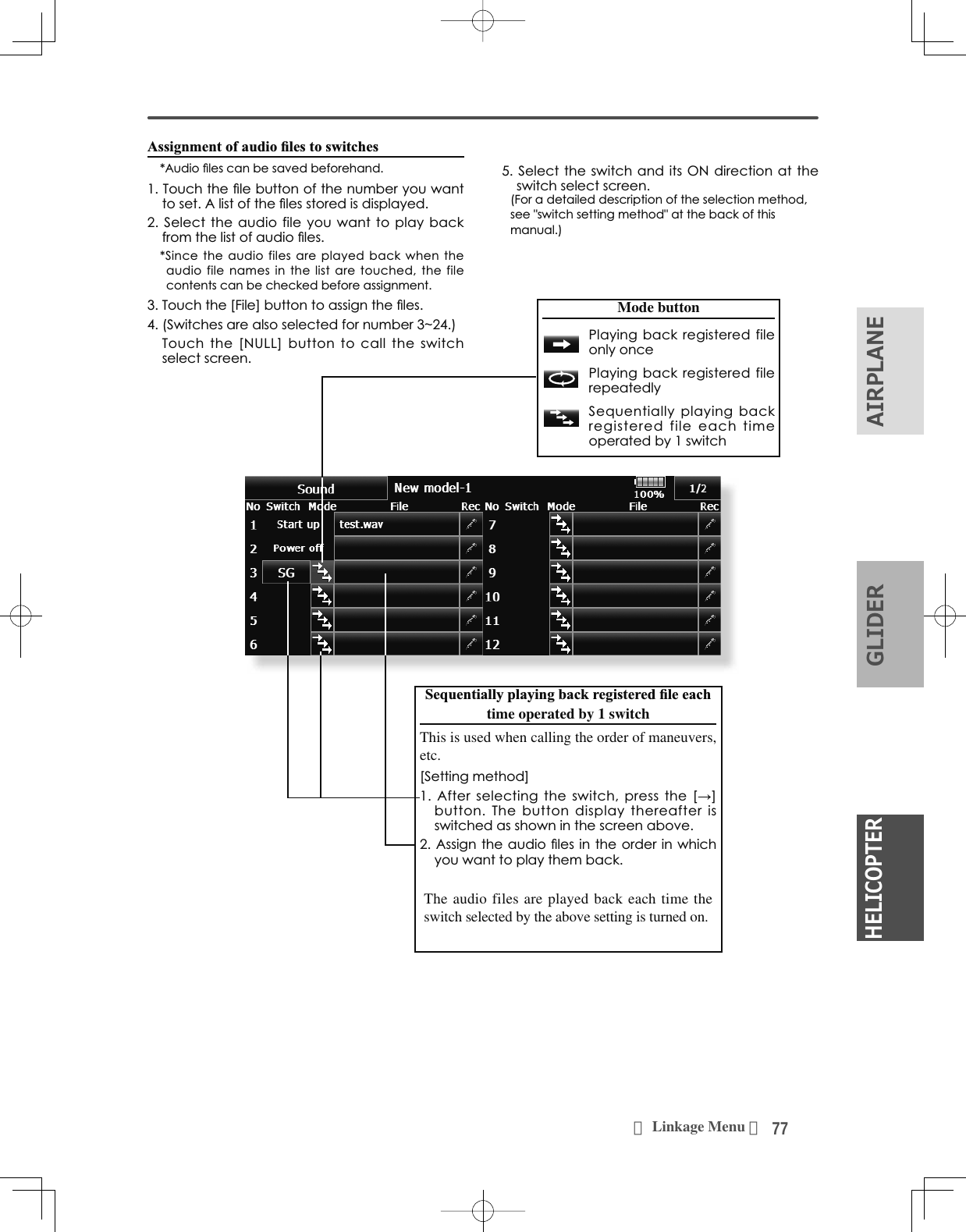
![76 <Linkage Menu >+(/,&237(5$,53/$1( */,'(5ŏ5HWXUQWR/LQNDJH0HQXŏ7RXFKWKH>6RXQG@EXWWRQLQWKH/LQNDJH0HQXWRFDOOWKHVHWXSVFUHHQVKRZQEHORZŏ7RXFKWKHÀOHEXWWRQ&RS\'HOHWH(QWU\5HQDPHLVPDGH,WLVWKHVDPHSURFHGXUHDVWKHSLFWXUHRIWKHSUHFHGLQJFODXVH6RXQG 6RXQGUHFRUGLQJDQGSOD\EDFN6DYHGVRXQG¿OH[Important]Before reading data from a PC, insert the SD card/USB memory into the transmitter and turn on the power. The following folders are automatically written. When reading a file from WKH3&FRS\LWWRDIROGHUE\¿OHW\SHŏ%033LFWXUHÀOH ŏ:$9$XGLRÀOHŏ:0$0XVLFÀOH ŏ02'(/0RGHOGDWDSounds recorded with the microphone built into the WUDQVPLWWHURUDQ\DXGLR¿OHVZDYFDQEHVHWWRWKHpower switch or any preset switch that you choose.2QO\DZDY¿OHVDYHGLQWKHVDPHVWRUDJHSODFH70=:&SD card, a USB memory) as the current model can be chosen.7KHPD[LPXPUHFRUGLQJWLPHIURPWKHPLFURSKRQHLVVHFRQGV7ZHQW\IRXUDXGLR¿OHVFDQEHVDYHG7KHRQO\DXGLR¿OHW\SHZKLFKFDQEHUHFRUGHGLVZDY2QO\the sounds recorded with the built-in microphone or an audio ¿OHVDYHGIURP\RXU3&WRDQ6'FDUGFDQEHSOD\HGEDFN6HWXSVFUHHQVQXPEHUWRFDQEHLQGLYLGXDOO\assigned to audio file switches, etc. The playback files can be switched each time the same switch is operated. This can be used when playing back the name of maneuvers, etc.>6RXQGVWDUWLQJ@:KHQWUDQVPLWWHUSRZHUVZLWFKWXUQHGRQ:KHQWUDQVPLWWHUSRZHUVZLWFKWXUQHGRIIa6ZLWFKFDQEHVHWVoice Recording7RXFKDQ\5(&EXWWRQWRFDOOXSWKH6281'5(&25'(5VFUHHQ7RXFKWKH5(&EXWWRQWRVWDUWUHFRUGLQJ5HFRUGLQJWLPHVHFRQGV5HFRUG\RXUYRLFHDV\RXDUHIDFLQJWKHWUDQVPLWWHU·VPLFURSKRQH6SHDNORXGO\DQGFOHDUO\7RILQLVKSUHVV´&/26(µ$OVRVRXQGILOHVFUHDWHGE\\RXU3&PD\EHSOD\HGEDFNE\DVVLJQHGVZLWFKHV)LOHW\SHVZDYÀOHRQO\$YRLFHÀOHLVVDYHG DXWRPDWLFDOO\WRWKHORFDWLRQRIWKHPRGHO\RX DUHFXUUHQWO\XVLQJ:KHWKHULQWKHWUDQVPLWWHU6'FDUGRU86%PHPRU\$ÀOHQDPHLVGLVSOD\HGRQWKHÀOHEXWWRQFRUUHVSRQGLQJWRDUHFRUGLQJEXWWRQ](https://usermanual.wiki/Futaba/T18MZWC-24G.User-Manual-1/User-Guide-2898093-Page-76.png)
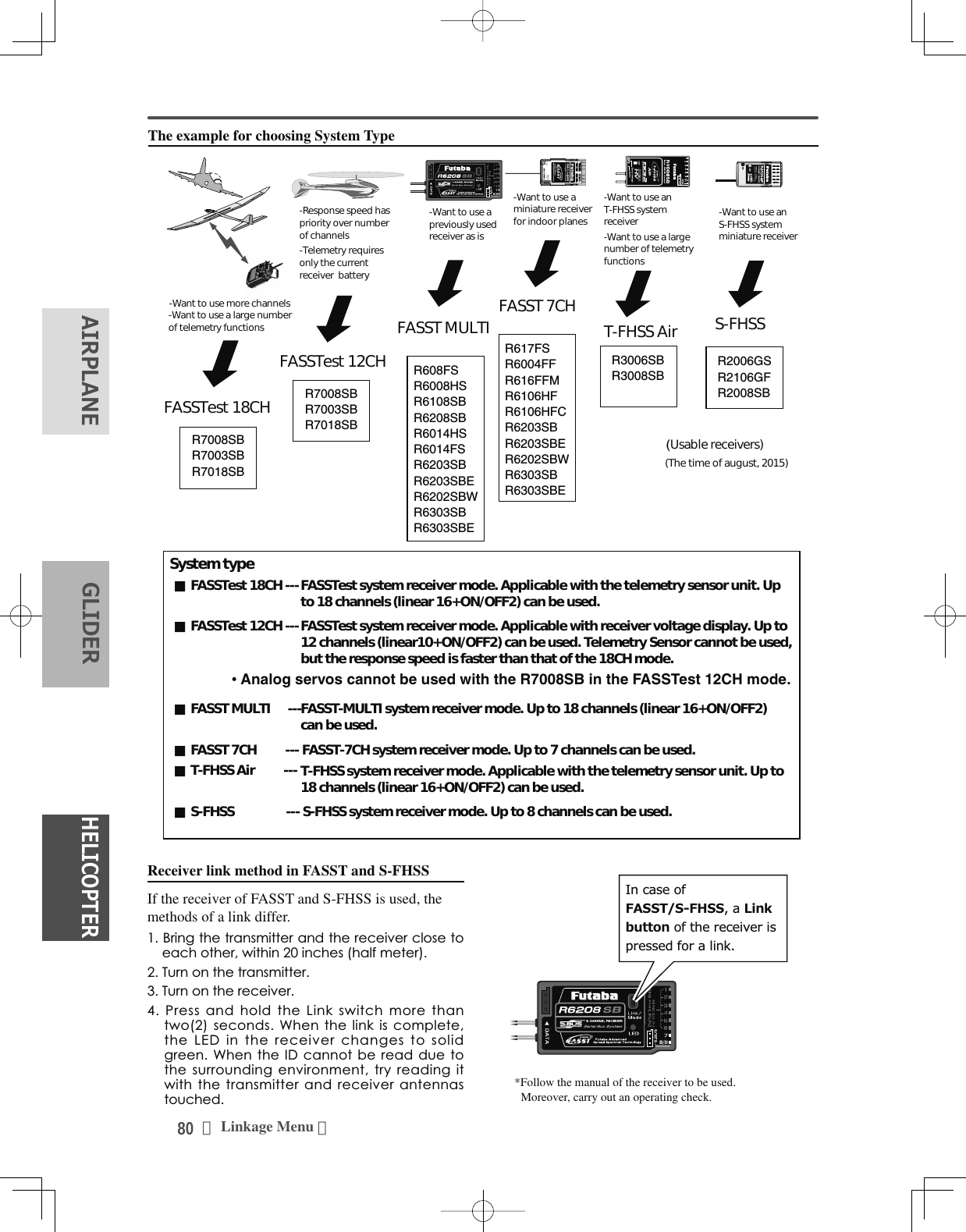
![78 <Linkage Menu >+(/,&237(5$,53/$1( */,'(5System Type selection7KH70=:&LVIRU*+]RQO\7KHV\VWHPcan be changed from among 5 choices: FASSTest 18CH, FASSTest 12CH, FASST MULTI, FASST 7CH, S-FHSS, T-FHSS. Select the system matched to the type of receiver you are using.u*Even if it changes a system type, other model data is not reset.e*If a system type is changed in the case of a helicopter, It can choose out of two channel orders. [Yes] : Selection sets the channel order suitable for system type. (We recommend here.)[No] : The present channel order is maintained.*All control surfaces should be checked for the correct operating directions and operating smoothness before À\LQJWKHPRGHO$QDORJVHUYRVFDQQRWEHXVHGZLWKWKH56%LQWKHFASSTest 12CH mode.Receiver linkingThe receiver will only be controlled (without being affected by other transmitters) by the transmitter it is linked to. When using a receiver other than one purchased as a set, linking is necessary.Moreover, a re-link is required when a new model is added by model selection, and the time of system type change.Dual receiver function (only FASSTest 18CH mode)Dual receivers can be linked with the T18MZ-:&7ZRUHFHLYHUVDUHUHFRJQL]HGLQGLYLGXDOO\E\,'QXPEHUV)RUH[DPSOHLQ56%&+output setting function is used, by setting the ¿UVWDVDV&+DQGVHWWLQJWKHVHFRQGDVŏ5HWXUQWR/LQNDJH0HQXŏ7RXFKWKH>6\VWHP7\SH@EXWWRQLQWKH/LQNDJH0HQXWRFDOOWKHVHWXSVFUHHQVKRZQEHORZ6\VWHP7\SH 6\VWHPPRGHVHWWLQJ5HFHLYHUOLQN&+WZRVHWVRIUHFHLYHUVFDQEHXVHGDVDVHWin the model, allowing you 16 channels. If a dual receiver function is used, the following function can set up individually.・Battery fail-safe voltage setup A telemetry function cannot be used for the 2nd receiver. 7KHYROWDJHDQG([WYROWDJHRIDQGreceiver cannot be known with a transmitter.Telemetry function (only FASSTest mode)To use the telemetry function, set “Telemetry” to “ON”.D/L Interval (only FASSTest mode)When a telemetry function is enabled, the receiving interval (down-link interval) of sensor data can be changed.If a D/L interval is increased, the response of the sensor data display becomes slower, but stick response will improve.Battery fail-safe voltage setup (FASSTest / T-FHSS mode)The voltage which battery fail-safe activates, can EHVHWZKHQ\RXOLQN97KHUHFHLYHUPHPRUL]HVWKHVHWWLQJDVLWZDVDWOLQNSuggested setting voltages are as follows.FHOOV1L&GRU1L0+1RUPDOY YFHOOV/L)H1RUPDOY aYFHOOV/L3R1RUPDOY aYIt is a rough reference value.Since it changes with servos carried in the condition and the model of a battery, please set to your own model in a battery consumption current.](https://usermanual.wiki/Futaba/T18MZWC-24G.User-Manual-1/User-Guide-2898093-Page-78.png)
![79<Linkage Menu >+(/,&237(5$,53/$1(*/,'(5WARNING Do not perform the linking operation when the drive motor is connected and the engine was started.■Inadvertent rotation of the motor or acceleration of the engine LVH[WUHPHO\GDQJHURXV Once the link operation is complete, please check that your receiver can be operated with the linked transmitter. CKHFNRSHUDWLRQVXI¿FLHQWO\EHIRUHÀ\LQJDIWHUlinking.■If the same receiver is sending in the vicinity, there is the danger that the transmitter may be linked with that receiver.CAUTION Always turn on the transmitter power after linking is complete. When pairing with the transmitter, be sure that a previously linked transmitter is not transmittingLinking method (T18MZ-WC ↔R7008SB)%ULQJWKHUHFHLYHUWREHOLQNHGWRZLWKLQFPRIWKHWUDQVPLWWHU3UHVVWKH>/LQN@EXWWRQLQWKH>/LQN@ER[RI>6\VWHP7\SH@7KHWUDQVPLWWHUHPLWVDFKLPHVRXQGDQGHQWHUVWKHOLQNPRGH7KHUHFHLYHUSRZHULVLPPHGLDWHO\WXUQHGRQ$ERXWVHFRQGVDIWHUWKHSRZHULVWXUQHGRQWKHUHFHLYHUHQWHUVWKHOLQNLQJVWDWH5HFHLYHUOLQNLQJWLPHLVDERXWVHFRQG,IOLQNLQJLVVXFFHVVIXOWKHUHFHLYHU/('FKDQJHVIURPUHGWRJUHHQWKHOLQNPRGHHQGVDQGWKHUHFHLYHU,'FRGHLVGLVSOD\HG,IOLQNLQJIDLOVDQHUURUPHVVDJHLVGLVSOD\HG%ULQJWKHWUDQVPLWWHUFORVHUWRWKHUHFHLYHUDQGUHSHDWWKHSURFHGXUHDERYHIURPVWHS'RQRWSHUIRUPWKHOLQNLQJRSHUDWLRQZKHQWKHGULYHPRWRULVFRQQHFWHGRUWKHHQJLQHLVUXQQLQJ:KHQ\RXXVHWZRUHFHLYHUVSOHDVHEHVXUHWRVHWXSDSULPDU\DQG VHFRQGDU\LQWKHGXDOPRGH6LQFHWZRVHWVRIUHFHLYHUVFDQQRWEHLQGLYLGXDOO\UHFRJQL]HGZLWKRXWXVLQJDSULPDU\DQGVHFRQGDU\VHWXSLWLVLPSRVVLEOHWRUHFHLYHWHOHPHWU\GDWDFRUUHFWO\<RXPXVWOLQN RQHUHFHLYHUDWDWLPH,IERWKSRZHUVXSSOLHVWRWKH UHFHLYHUVDUHVZLWFKHGRQVLPXOWDQHRXVO\GDWDLVUHFHLYHG LQFRUUHFWO\E\WKHWUDQVPLWWHU$WHOHPHWU\IXQFWLRQ FDQQRWEHXVHGIRUWKH QGUHFHLYHU<RXFDQQRWOLQNWKUHHVHWVRIUHFHLYHUV/LQNLVUHTXLUHGZKHQDV\VWHPW\SHLVFKDQJHG/LQNLVUHTXLUHGZKHQDQHZPRGHOLVPDGHIURPDPRGHOVHOHFWLRQŏ7RXFKWKH>/LQN@EXWWRQLQWKH6\VWHP7\SH0HQXWRFDOOWKHVHWXSVFUHHQVKRZQEHORZŏ%DWWHU\IDLOVDIHYROWDJHVHWXSRQO\)$667HVWPRGHŏ5HWXUQWR6\VWHP7\SH0HQX](https://usermanual.wiki/Futaba/T18MZWC-24G.User-Manual-1/User-Guide-2898093-Page-79.png)
![81<Linkage Menu >+(/,&237(5$,53/$1(*/,'(5ŏ5HWXUQWR/LQNDJH0HQXŏWR>6:$3@ŏ7RXFKWKH>)XQFWLRQ@EXWWRQLQWKH/LQNDJH0HQXWRFDOOWKHVHWXSVFUHHQVKRZQEHORZ)XQFWLRQ &KDQQHODVVLJQPHQWIRUHDFKIXQFWLRQFDQEHFKDQJHGWRVXLW\RXUQHHGVWhen you select model and wing (swash) types, you ZLOOILQGWKDWWKHRSWLPL]HGFRPELQDWLRQVRIVHUYRoutput channels and functions have been already preset. If you would like, on the function-setting screen of the linkage menu, you can freely change combinations of servo output channels, functions (aileron, elevator, etc), and input controllers (sticks, switches, trim levers and trim switches). You can also assign the same function to multiple servo output channels such as assigning elevator function to CH2 and CH3.7KHGLVSOD\VFUHHQLVDQH[DPSOH7KHVFUHHQGHSHQGVRQWKHPRGHOW\SHFunction change7RXFKWKHIXQFWLRQEXWWRQRIWKHFKDQQHO\RXZDQWWRFKDQJHWRFDOOWKHIXQFWLRQOLVW6HOHFWWKHIXQFWLRQ\RXZDQWWRFKDQJH7RXFK><HV@7KHGLVSOD\UHWXUQVWRWKHRULJLQDOVFUHHQ:KHQ\RXZDQWWRFDQFHOIXQFWLRQFKDQJHWRXFK>1R@0XOWLSOHFKDQQHOVFDQEHDVVLJQHGWRIXQFWLRQ0XOWLSURSLVDQRSWLRQDO REMHFWIRU0XOWLSURSGHFRGHUV&+ZKLFKFDQEH0XOWLSURSVHWXS!)$667HVW&+7)+66&+)$667HVW&+QRWVHW)$66708/7,&+)$667&+QRWVHW6)+66QRWVHWDG1, DG2 (switch channels)These two channels can be used as switch (On/Off) channels. You can freely change combinations between servo output channels and input controllers(sticks, switches, trim levers and trim switches).Channel restrictions by a System TypeFASSTest 18CH/T-FHSS---16 CH+2 Switch)$667HVW&+&+6ZLWFKFASST MULTI ---16 CH+2 SwitchFASST 7CH --- 7 CHS-FHSS --- 8 CHOperation control change7RXFKWKHFRQWUROEXWWRQRIWKHFKDQQHO\RXZDQWWRFKDQJH$FRQWUROVHOHFWVFUHHQVWLFNVZLWFKNQREWULPOHYHUHWFLVGLVSOD\HG6HOHFWWKHFRQWURO\RXZDQWWRRSHUDWH7RXFK>&ORVH@7KHGLVSOD\UHWXUQVWRWKHSUHFHGLQJVFUHHQ7KHVDPHFRQWUROFDQEHDVVLJQHGWRPXOWLSOHFKDQQHOV](https://usermanual.wiki/Futaba/T18MZWC-24G.User-Manual-1/User-Guide-2898093-Page-81.png)
![82 <Linkage Menu >+(/,&237(5$,53/$1( */,'(57KHGLVSOD\VFUHHQLVDQH[DPSOH7KHVFUHHQGHSHQGVRQWKHPRGHOW\SHTrim change7RXFKWKHWULPEXWWRQWRFDOOWKHWULPVHWXSVFUHHQ7KHIROORZLQJLWHPVFDQEHVHWDWWKHWULPVHWXSVFUHHQŏ+DUGZDUHVHWWLQJ6HOHFWLRQRIVZLWFKHWFZKLFKFRQWUROVWULP7KHVHOHFWVFUHHQLVFDOOHGE\WRXFKLQJWKH>+:6HOHFW@EXWWRQŏ5DWHVHWWLQJŏ2SHUDWLRQVWHSVHWWLQJŏ7ULPPRGHVHWWLQJ1RUPDOPRGH1RUPDOWULPOLQHDURSHUDWLRQSWAPIf [SWAP] is pushed, it will call up the following screen. You can easily change two separate functions, keeping the data that was set for each channel.6HOHFWWKH7ULPEXWWRQIRUWKHWZRIXQFWLRQV\RXVHOHFWHGWR6ZDSWRVHWXSWKHWULPVDSSURSULDWHO\,I>2.@LVSXVKHGWZRFKDQQHOVZLOOLQWHUFKDQJH,WFDQFKRRVHRQO\WRWZR$7/PRGH$7/RSHUDWLRQPRGH:RUNVDWRQO\RQHHQGRIRSHUDWLRQ5HYHUVHLVDOVRSRVVLEOH&750PRGH0D[LPXPFKDQJHQHDUFHQWHUE\FHQWHUWULPRSHUDWLRQ'RHVQRWFKDQJHDWHQGRIWKHVWLFNPRYHPHQWŏ6HSDUDWHFRPELQDWLRQPRGH7ULPGDWDFDQEHVHWWRGLIIHUHQWÁLJKWFRQGLWLRQV6HSDUDWHPRGH7ULPDGMXVWPHQWIRUHDFKVHSDUDWHÁLJKWFRQGLWLRQ](https://usermanual.wiki/Futaba/T18MZWC-24G.User-Manual-1/User-Guide-2898093-Page-82.png)
![84 <Linkage Menu >+(/,&237(5$,53/$1( */,'(5ŏ5HWXUQWR/LQNDJH0HQXŏ7RXFKWKH>6HUYR5HYHUVH@EXWWRQLQWKH/LQNDJH0HQXWRFDOOWKHVHWXSVFUHHQVKRZQEHORZ6HUYR5HYHUVH 8VHWRUHYHUVHWKHVHUYRWKURZGLUHFWLRQ7KHGLVSOD\VFUHHQLVDQH[DPSOH7KHVFUHHQGHSHQGVRQWKHPRGHOW\SHServo Reverse changes the direction of an individual servo’s response to a control stick movement.For CCPM helicopters, be sure to read the section on Swash AFR before reversing any servos. With CCPM helicopters, always complete your servo reversing prior to any other programming. If you XVHSUHEXLOW$LUSODQH*OLGHUIXQFWLRQVWKDWFRQWUROmultiple servos, it may be confusing to tell whether the servo needs to be reversed or a setting in the function needs to be reversed. See the instructions IRUHDFKVSHFLDOL]HGIXQFWLRQIRUIXUWKHUGHWDLOVServo reversing procedureAfter setting up a new model, be sure to define all special menus. Be sure that all servos are plugged into the proper receiver channels. Now, determine whether you need to reverse any channels by moving each stick and observing the corresponding movement in the model’s controls. 7RXFKWKHGHVLUHGFKDQQHO·VVHWWLQJEXWWRQWRFKRRVHWKHSURSHUGLUHFWLRQIRUWKHVHUYR7RXFK´<HVµLQWKHQH[WVFUHHQ5HSHDWIRUHDFKVHUYRQHHGLQJUHYHUVDO:KHQGRQHWRXFK´6HUYR5HYHUVHµWRUHWXUQWRWKH/LQNDJH0HQXAlways check servo direction prior to every flight DVDQDGGLWLRQDOSUHFDXWLRQWRFRQ¿UPSURSHUPRGHOmemory, hook ups, and radio function.WARNINGBefore a flight, always check that your models servo operation, the direction of control surfaces, and switch setup are correct.Default setting of the motor channel is always reverse.](https://usermanual.wiki/Futaba/T18MZWC-24G.User-Manual-1/User-Guide-2898093-Page-84.png)
![85<Linkage Menu >+(/,&237(5$,53/$1(*/,'(5ŏ5HWXUQWR/LQNDJH0HQXŏ7RXFKWKH>)DLO6DIH@EXWWRQLQWKH/LQNDJH0HQXWRFDOOWKHVHWXSVFUHHQVKRZQEHORZ)DLO6DIH 6HWVWKHVHUYRVRSHUDWLQJSRVLWLRQZKHQWUDQVPLWWHUVLJQDOVFDQQRORQJHUEHUHFHLYHGRUZKHQWKHUHFHLYHUEDWWHU\YROWDJHGURSV7KHGLVSOD\VFUHHQLVDQH[DPSOH7KHVFUHHQGHSHQGVRQWKHPRGHOW\SHThe Failsafe function is used to set up positions that the servos will move to in the case of radio LQWHUIHUHQFH'H¿QHVVHUYRSRVLWLRQZKHQVLJQDOVDUHlost and when receiver battery voltage becomes low.You may set either of two positions for each channel: Hold, where the servo maintains its last commanded position, or fail safe, where each servo moves to a predetermined position. You may choose either mode for each channel.The T18MZ-WC system also provides you with an advanced battery monitoring function that warns you when the receiver battery has only a little power remaining. In this case, each servo is moved to the defined failsafe position. The battery failsafe may EHUHOHDVHGE\RSHUDWLQJDSUHGH¿QHGFRQWURORQWKHtransmitter (default is throttle). Do not continue to fly, land as soon as possible. Remember, if the Fail safe setting procedureDecide which channels you want to go to preset positions, and which ones you want to maintain their last commanded position. To select the fail safe mode you wish to set, use the F/S button. This button toggles between the two modes. (Hold, F/S)F/S mode setting:7RXFKWKH)6EXWWRQRIWKHFKDQQHO\RXZDQWWRVHWDQGVHWWKDWFKDQQHOWRWKH>)6@PRGH+ROGWKHFRUUHVSRQGLQJVWLFNFRQWUROVOLGHURURWKHUFRQWUROLQWKHSRVLWLRQ\RXZDQWWKHVHUYRWRPRYHWRZKHQWKHIDLOVDIHIXQFWLRQLVDFWLYDWHGDQGWRXFKWKH)6SRVLWLRQEXWWRQ7KDWSRVLWLRQLVGLVSOD\HGLQSHUFHQWDJH:KHQ\RXZDQWWRUHWXUQWKDWFKDQQHOWRWKH+ROGPRGHWRXFKWKH>)6@EXWWRQDJDLQBattery fail safe setting procedureTo select the B.F/S mode, touch the [B.F/S] button. Each time the button is touched, it toggles between [OFF] and [B.F/S].predefined control suddenly moves to a position you did not command, land at once and check your receiver battery.Do not continue to fly, land as soon as possible.Defines servo position when signals are lost and when receiver battery voltage becomes low.WARNING For safety, always set the fail safe functions.■Especially set the throttle channel fail safe function so that WKHVHUYRPRYHVWRWKHPD[LPXPVORZVLGHIRUDLUSODQHVDQGto the slow side from the hovering position for helicopters. Crashing of the model at full high when normal radio waves cannot be received due to interference, etc., is very dangerous.■If fail safe is reset by throttle stick movement, the fail safe may be mistaken as an engine malfunction and will be reset DWORZWKURWWOHDQGWKHPRGHOZLOOFRQWLQXHWRÀ\,I\RXKDYHany doubts, immediately land.B.F/S setting:7RXFKWKH>%)6@EXWWRQRIWKHGHVLUHGFKDQQHOWRVHWLWWRWKH%)6PRGH+ROGWKHFRUUHVSRQGLQJVWLFN95VOLGHURURWKHUFRQWUROLQWKHSRVLWLRQ\RXZDQWWKHVHUYRWRPRYHWRZKHQWKHEDWWHU\IDLOVDIHIXQFWLRQLVDFWLYDWHGDQGWRXFKWKH)6SRVLWLRQEXWWRQ7KLVSRVLWLRQLVGLVSOD\HGLQSHUFHQWDJH:KHQ\RXZDQWWR UHWXUQWKDWFKDQQHOWR2))WRXFKWKH>%)6@EXWWRQDJDLQBattery Fail safe Release FunctionThis function releases the predefined control from it's held position after indicating that your receiver battery is low. (QWHUWKHFRQWUROVHWWLQJ VFUHHQE\WRXFKLQJWKH%DWWHU\)65HOHDVHEXWWRQ1RZ\RXPD\FKRRVHZKHWKHUPRYLQJWKHWKURWWOHUHVHWVWKHFRQGLWLRQRUVHOHFWDVWLFNRUVZLWFKWRGHDFWLYDWHLW7RVHWDGHVLUHGWKURWWOHUHOHDVHSRVLWLRQPRYHWKHWKURWWOHVWLFNWRWKHSRLQWDWZKLFK\RXZLVKWKH%)6WREHUHOHDVHGŏ7R6ZLWFK!VFUHHQ](https://usermanual.wiki/Futaba/T18MZWC-24G.User-Manual-1/User-Guide-2898093-Page-85.png)
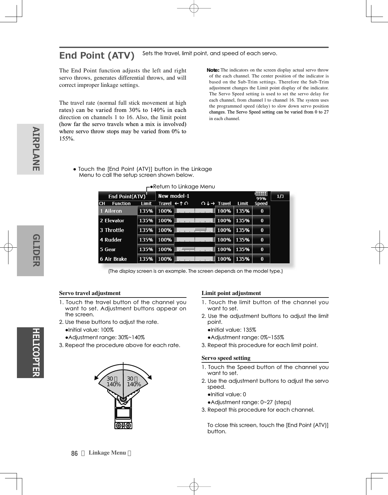
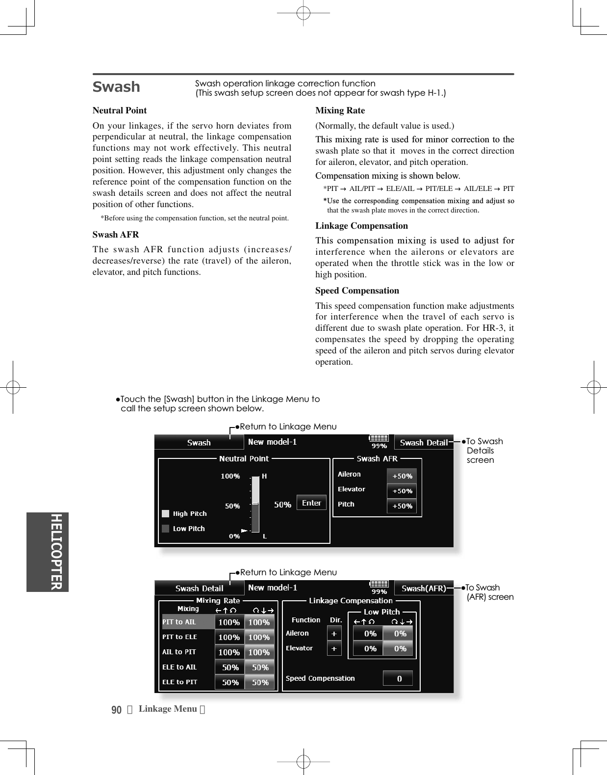
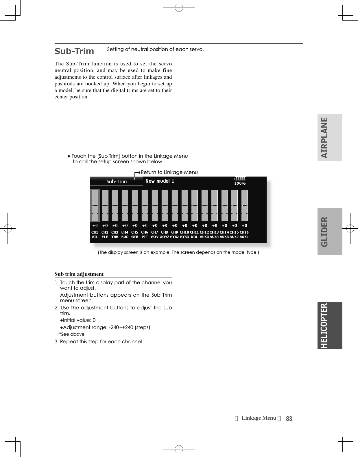
![91<Linkage Menu >+(/,&237(5$,53/$1(*/,'(5Neutral point setting procedure%HFRPHVWKHFRPSHQVDWLRQUHIHUHQFHSRLQW$GMXVWLQJWKHVHUYRKRUQVRWKDWWKHQHXWUDOSRLQWSRVLWLRQLVQHDUWKH SRVLWLRQPDNHVWKHPL[LQJDPRXQWVPDOO+ROGWKHVHUYRKRUQDWDULJKWDQJOHWRWKHOLQNDJHURGDQGWKHQWRXFKWKH>(QWHU@EXWWRQDQGUHDGWKHDFWXDOQHXWUDOSRLQW7KHQHXWUDOSRLQWLVGLVSOD\HGRQWKHVFUHHQ $IWHUUHDGLQJWKLVQHXWUDOSRLQWXVHRWKHUFRPSHQVDWLRQIXQFWLRQVWRPDNHIXUWKHUDGMXVWPHQWV 7RH[LWWKHVHWWLQJWRXFKWKH>6ZDVK@EXWWRQSwash AFR setting procedure $GMXVWVRWKDWWKHVSHFLÀHGRSHUDWLRQDPRXQWLVREWDLQHGE\DLOHURQHOHYDWRUDQGSLWFKRSHUDWLRQ7RXFKWKHEXWWRQRIWKH$)5UDWHWREHDGMXVWHG$GMXVWPHQWEXWWRQVDSSHDURQWKHVFUHHQ8VHWKHDGMXVWPHQWEXWWRQVWRDGMXVWWKH$)5UDWH ,QLWLDOYDOXH $GMXVWPHQWUDQJHaRUWKHGLUHFWLRQRIRSHUDWLRQFKDQJHV 7RH[LWVHWWLQJWRXFKWKH>6ZDVK@EXWWRQMixing rate setting procedure+5LVGHVFULEHGDVDQH[DPSOH7KHPL[LQJDSSOLHGLQRWKHUVZDVKPRGHVLVGLIIHUHQWEXWWKHVHWWLQJSURFHGXUHLVWKHVDPH6HWWKHWKURWWOHVWLFNWRWKHVHWQHXWUDOSRLQW$GMXVWWKHOHQJWKRIWKHOLQNDJHURGVRWKDWWKHVZDVKSODWHLVKRUL]RQWDODWWKLVSRVLWLRQ$OLWWOHDGMXVWPHQWXVLQJVXEWULPVKRXOGEH2.$GMXVWVRWKDWSLWFKRSHUDWLRQZKHQWKHSLWFKFXUYHLVVWUDLJKWLVPD[LPXP$GMXVWWKH$,/ →3,7DPRXQWVRWKHUHLVQRLQWHUIHUHQFHLQWKHHOHYDWRURUSLWFKGLUHFWLRQZKHQWKHDLOHURQVWLFNLVPRYHGWRWKHOHIWDQGULJKW$GMXVWWKHOHIWDQGULJKWVLGHVVHSDUDWHO\$GMXVWWKH(/( →$,/DQG(/( →3,7DPRXQWVVRWKHUHLVQRWLQWHUIHUHQFHLQWKHDLOHURQRUSLWFKGLUHFWLRQZKHQWKHHOHYDWRUVWLFNLVPRYHGXSDQGGRZQ$GMXVWWKHXSDQGGRZQVLGHVVHSDUDWHO\$GMXVWWKH3,7 →$,/DQG3,7 →(/(DPRXQWVVRWKDWWKHVZDVKSODWHLVKRUL]RQWDOZKHQWKHWKURWWOHVWLFNLVVHWWRPD[LPXPVORZDQGIXOOKLJK$GMXVWWKHVORZDQGKLJKVLGHVVHSDUDWHO\7RH[LWVHWWLQJWRXFKWKH>6ZDVK'HWDLOV@EXWWRQLinkage correction setting procedure6HWWKHOLQNDJHFRPSHQVDWLRQDIWHUVHWWLQJWKHPL[LQJUDWH7KLVIXQFWLRQFRPSHQVDWHVIRUHOHYDWRULQWHUIHUHQFHE\DLOHURQRSHUDWLRQRUDLOHURQLQWHUIHUHQFHE\HOHYDWRURSHUDWLRQDW/RZSLWFKDQG+LSLWFKDWFROOHFWLYHSLWFK+5HWFFRQWURO6HWWKHWKURWWOHVWLFNWRWKHPD[LPXPVORZSRVLWLRQ0RYHWKHDLOHURQVWLFNWRWKHOHIWDQGULJKWDQGDGMXVWWKHDLOHURQFRPSHQVDWLRQDPRXQWVRWKDWLQWHUIHUHQFHLQWKHHOHYDWRURUSLWFKGLUHFWLRQDWWKDWWLPHLVPLQLPDO7KHOHIWDQGULJKWVLGHVFDQEHDGMXVWHGVHSDUDWHO\,IWKHLQWHUIHUHQFHLQFUHDVHVZKHQWKHFRPSHQVDWLRQDPRXQWLVLQFUHDVHGPDNHWKHFRPSHQVDWLRQGLUHFWLRQ$GMXVWWKHHOHYDWRUFRPSHQVDWLRQDPRXQWVRWKDWWKHLQWHUIHUHQFHLQWKHDLOHURQRUSLWFKGLUHFWLRQZKHQWKHHOHYDWRUVWLFNZDVPRYHGXSDQGGRZQLVPLQLPDO3HUIRUPDLOHURQDQGHOHYDWRUFRPSHQVDWLRQVLPLODUO\IRUWKHWKURWWOHVWLFNIXOOKLJKVLGH7RH[LWVHWWLQJWRXFKWKH>6ZDVK'HWDLOV@EXWWRQSpeed compensation setting procedure6HWWKHWKURWWOHVWLFNWRWKHQHXWUDOSRLQWSRVLWLRQ0RYHWKHHOHYDWRUVWLFNTXLFNO\DQGDGMXVWWKHVSHHGFRPSHQVDWLRQDPRXQWVRWKDWWKHLQWHUIHUHQFHLQWKHSLWFKGLUHFWLRQLVPLQLPDO7RH[LWVHWWLQJWRXFKWKH>6ZDVK'HWDLOV@EXWWRQNote: ,IWKHOLQNDJHLVWRRORQJRUVKRUWFRUUHFWFRPSHQVDWLRQZLOOQRWEHDSSOLHG&RUUHFWWKLVEHIRUHFRQWLQXLQJ7KHSLWFKDQJOHFKDQJHVDIWHUDQ\DGMXVWPHQW5HVHWWKHSLWFKDQJOHZKHQDFWXDOO\IO\LQJDIWHUFRPSHQVDWLRQSURFHVVLQJ](https://usermanual.wiki/Futaba/T18MZWC-24G.User-Manual-1/User-Guide-2898093-Page-91.png)
![92 <Linkage Menu >+(/,&237(5$,53/$1( */,'(5ŏ0HPRU\LVWXUQHG21WKHSRZHU2))DQGDPRGHOFKDQJHZLOOQRWEHUHVHWWLPHUHLWKHUŏ>Ń@$QDODUPVRXQGVHYHU\PLQXWHRIWKHHODSVHG WLPHIURPWLPHUVWDUW&RQYHQWLRQDOPRGH>Ņ@$QDODUPVRXQGVHYHU\PLQXWHRIWKHUHPDLQLQJWLPHXSWRWKHDODUPWLPHŏ 7RXFKWKH>7LPHU@EXWWRQLQWKH/LQNDJH0HQXWRFDOOWKHVHWXSVFUHHQVKRZQEHORZ7LPHU 7LPHUVHWWLQJDQGODSWLPHGLVSOD\The Timer function may be set for any desired time, LHHQJLQHUXQWLPHVSHFL¿HGWLPHVIRUFRPSHWLWLRQVetc. Two independent timers are provided for your use. The timers are stored independently with each model, meaning that when you switch between model setups, the timer associated with the new model is brought up automatically.The timers may be set to start and stop from the motion of any switch or stick. You may set the ON and OFF directions freely. Each timer has a capacity RIXSWRPLQXWHVVHFRQGVUp timer/Down timer/Hour selection7RXFKWKHPRGHEXWWRQDQGVHOHFWWKHW\SHRIWLPHU7LPHUWLPHVHWWLQJ7RXFKWKH0RGHPLQXWHVRUVHFRQGVEXWWRQ$GMXVWPHQWEXWWRQVDSSHDURQWKHVFUHHQ8VHWKHVHEXWWRQVWRVHWWKHWLPHUWLPHStart/SWtop switch setting7RXFKWKH6WDUW6WRS6: 18//EXWWRQWRFDOOWKH6ZLWFK!VFUHHQDQGWKHQVHOHFWWKHVZLWFKDQGLWV21GLUHFWLRQ)RUDGHWDLOHGGHVFULSWLRQRIWKHVHOHFWLRQPHWKRGVHH>6ZLWFK6HWWLQJ0HWKRG@DWWKHEDFNRIWKLVPDQXDO7KHWLPHUVZLWFKHVFDQEHVHWIRUHDFKFRQGLWLRQLap time switch selection7RXFKWKH/DS6:18//EXWWRQWRFDOOWKH3URJ0L[VFUHHQDQGWKHQVHOHFWWKHVZLWFKDQGLWV21GLUHFWLRQ)RUDGHWDLOHGGHVFULSWLRQRIWKHVZLWFKVHWWLQJPHWKRGVHH>6ZLWFK6HWWLQJ0HWKRG@DWWKHEDFNRIWKLVPDQXDO7KHWLPHUVZLWFKHVFDQEHVHWIRUHDFKFRQGLWLRQEach timer may be set for count-down or count up operation with your choice of a target time. Also split time may be set up and counted.If a target time is set and the timer reaches this point, DEX]]HUZLOOVRXQGIRUHDFKFRXQWJHQHUDWHGCountdown timers sound one short beep during the last twenty seconds and two short beeps during the last ten seconds before reaching the target, then a long tone at the target time, and continue counting with displaying a minus (-) sign. Count-up timers also beep the last twenty and ten seconds, beep the target time, and keep counting upwards until shut down.Timer operationŏ7LPHUDQG7LPHUDUHVWDUWHGDQGVWRSSHGE\\RXUFKRLFHRIVZLWFKŏ7RFRXQWWKHODSWLPHVHOHFWWKHODSWLPHVZLWFK(DFKWLPHWKLVVZLWFKLVRSHUDWHGWKHODSWLPHLVVWRUHG7RGLVSOD\WKHODSWLPHWRXFKWKHUHVSHFWLYH>/LVW@EXWWRQŏ7RUHVHWDWLPHUWRXFKWKHUHVSHFWLYH>5HVHW@EXWWRQ7RH[LWWKHVHWWLQJ WRXFKWKH>7LPHU@EXWWRQHour mode$Q+285PRGHZKLFKFRXQWVXSWRKRXUVPLQXWHVKDVEHHQDGGHGWRWKHWLPHUPRGHVŏ7KLVPRGHLVFRQYHQLHQWZKHQXVHGDWHQJLQHPDLQWHQDQFHSHULRGDQGRWKHUORQJWHUPPHDVXUHPHQWVŏ:KHQWKH+285PRGHLVVHW´[[KRXU[[PLQXWHµLVGLVSOD\HGRQWKHFRXQWWLPHGLVSOD\6HFRQGVDUHQRWGLVSOD\HGŏ:KHQWKH+285PRGHLVVHW´µEOLQNVHDFKVHFRQGGXULQJWLPHURSHUDWLRQŏ:KHQWKH+285PRGHLVVHWWKHDODUPIXQFWLRQODSWLPHPHDVXUHPHQWIXQFWLRQDUHLQKLELWHGŏ5HWXUQWR7LPHUVFUHHQ<Lap time list>ŏ5HWXUQWR/LQNDJH0HQX](https://usermanual.wiki/Futaba/T18MZWC-24G.User-Manual-1/User-Guide-2898093-Page-92.png)