Contents
- 1. User Manual 1
- 2. User Manual 2
User Manual 1
1M23N26421
INSTRUCTION MANUAL
TM

2<TABLE OF CONTENTS >
,1752'8&7,21
ٴ 6XSSRUWDQG6HUYLFH
ٴ $SSOLFDWLRQ([SRUWDQG0RGLrFDWLRQ
ٴ 'HrQLWLRQVRI6\PEROV
ٴ 6DIHW\3UHFDXWLRQVGRQRWRSHUDWH
ZLWKRXWUHDGLQJ
%()25(86(
ٴ )HDWXUHVRI0=:&
ٴ &RQWHQWVDQG7HFKQLFDO6SHFLrFDWLRQV
ٴ $FFHVVRULHV
ٴ 7UDQVPLWWHUFRQWUROV
&DXWLRQVRQKDQGOLQJDQWHQQD
/('PRQLWRU
6ZLWFKUHDOORFDWLRQ6$6+
9ROXPH/'&'5'
6OLGH/HYHU/67/656567
'LJLWDOWULP77
7RXFKSDQHO5RWDU\NH\'LUHFWNH\
7RXFKSDQHOORFN
6WLFN$GMXVWPHQW
%DWWHU\H[FKDQJH
%DFNOLG
&RQQHFWRU3OXJ
6'FDUG86%SRUW
&DPHUDIXQFWLRQ
ٴ 5HFHLYHU56%QRPHQFODWXUH
&RQQHFWRU
/LQN0RGH6ZLWFK
([WUD9ROWDJH&RQQHFWRU
&RQQHFWLRQRIDUHFHLYHUEDWWHU\
&RQQHFWLRQH[DPSOH
56%&+0RGH
ٴ 6HUYR2SWLRQ7RROER[
ٴ 5HFHLYHUV$QWHQQD,QVWDOODWLRQ
ٴ 6DIHW\SUHFDXWLRQVZKHQLQVWDOOLQJ
UHFHLYHUDQGVHUYRV
ٴ 6%86,QVWDOODWLRQ
ٴ 6%86:LULQJH[DPSOH
ٴ 6%866\VWHP
ٴ 6%86GHYLFHVHWWLQJ
ٴ 7HOHPHWU\6\VWHP
%$6,&23(5$7,21
ٴ %DWWHU\&KDUJLQJ
ٴ +RZWRWXUQ212))WKHWUDQVPLWWHU
ٴ 5HJLVWUDWLRQRIWKHXVHUVQDPH
ٴ +RPHVFUHHQ
ٴ +RPHVFUHHQ
ٴ 8VHU0HQX
02'(/%$6,&6(77,1*352&('85(
ٴ $LUSODQHJOLGHUEDVLFVHWWLQJSURFHGXUH
ٴ +HOLFRSWHUEDVLFVHWWLQJSURFHGXUH
ٴ 6HUYRVFRQQHFWLRQE\PRGHOW\SH
)81&7,2162)6<67(00(18
7UDLQHU
'LVSOD\
'DWHDQG7LPH
8VHU1DPH
6ZLWFK
+:6HWWLQJ
6RXQG9ROXPH
3OD\HU
&DPHUD
6%866HUYR
,QIRUPDWLRQ
8QLW6\VWHP
5DQJH&KHFN
)81&7,2162)/,1.$*(0(18
6HUYR0RQLWRU
0RGHO6HOHFW
0RGHO7\SH
3LFWXUH
6RXQG
6\VWHP7\SH
6\VWHP7\SHVHOHFWLRQ
5HFHLYHUOLQNLQJ
'XDOUHFHLYHUIXQFWLRQ
7HOHPHWU\IXQFWLRQ
7$%/(2)&217(176

3
<TABLE OF CONTENTS >
'/,QWHUYDO
%DWWHU\IDLOVDIHYROWDJHVHWXS
/LQNLQJPHWKRG70=:&ܯ56%
7KHH[DPSOHIRUFKRRVLQJ6\VWHP7\SH
)XQFWLRQ
6XE7ULP
6HUYR5HYHUVH
)DLO6DIH
(QG3RLQW$79
7KURWWOH&XW$LUSODQHKHOLFRSWHURQO\
,GOH'RZQ$LUSODQHKHOLFRSWHURQO\
6ZDVK5LQJ+HOLFRSWHURQO\
6ZDVK+HOLFRSWHURQO\
7LPHU
'LDO0RQLWRU
)XQFWLRQ1DPH
7HOHPHWU\
$XGLEOHWHOHPHWU\LQIRUPDWLRQ
5HFHLYHU%DWWHU\'LVSOD\
7HPSHUDWXUH'LVSOD\
530'LVSOD\
$OWLWXGH'LVSOD\
*36'LVSOD\
9ROWDJH'LVSOD\
&XUUHQW9ROWDJH&DSDFLW\'LVSOD\
6HUYRVHQVRU'LVSOD\
6HQVRU
6HQVRU1DPH
7HOHPHWU\6HWWLQJ
:DUQLQJ
'DWD5HVHW
&RQGLWLRQ+ROG+HOLFRSWHURQO\
)81&7,2162)02'(/0(18
6HUYR0RQLWRU/LQNDJH0HQX
&RQGLWLRQ6HOHFW
$)5'5
3URJ0L[HV3URJUDPPL[LQJ
)XHO0L[WXUH
ٴ $LUSODQH*OLGHU)XQFWLRQV
$,/'LíHUHQWLDO
)ODS6HWWLQJ
$,/WR&DPEHU)/3
$,/WR%UDNH)/3
$,/WR58'
$LUEUDNHWR(/(
58'WR$,/
&DPEHU0L[
(/(WR&DPEHU
&DPEHU)/3WR(/(
%XWWHUs\
7ULP0L[
$LUEUDNH
*\UR$LUSODQH
9WDLO
$LOHYDWRU
:LQJOHW
0RWRU
58'WR(/(
6QDS5ROO
0XOWL(QJLQH
$FFHOHUDWLRQ
ٴ +HOLFRSWHU)XQFWLRQV
3,7&XUYH
7+5&XUYH
$FFHOHUDWLRQ
7KURWWOH+ROG
6ZDVK0L[
7KURWWOH0L[
3,7WR1HHGOH
3,7WR58'
*\UR
*RYHUQRU
7KURWWOH/LPLWHU
&2002123(5$7,21686(',1
)81&7,216(7836&5((1
)OLJKWFRQGLWLRQV
)LQHWXQLQJ95VHWWLQJ
6HUYRVSHHG
&XUYHVHWWLQJ
6ZLWFKVHOHFWLRQ
83'$7,1*
70=ڀ 70=:&02'(/'$7$
&219(56,21

4<Introduction >
,1752'8&7,21
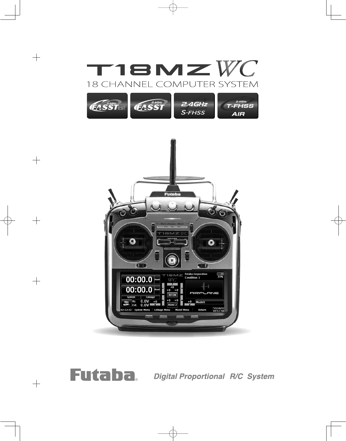
Thank you for purchasing a Futaba® FASSTest-2.4GHz*18MZ-WC series digital proportional R/C
system. This system is extremely versatile and may be used by beginners and pros alike. In order for
\RXWRPDNHWKHEHVWXVHRI\RXUV\VWHPDQGWRÀ\VDIHO\SOHDVHUHDGWKLVPDQXDOFDUHIXOO\ ,I \RX
KDYHDQ\GLI¿FXOWLHVZKLOHXVLQJ\RXUV\VWHPSOHDVHFRQVXOWWKHPDQXDORXURQOLQH)UHTXHQWO\$VNHG
4XHVWLRQVRQWKHZHESDJHVUHIHUHQFHGEHORZ\RXUKREE\GHDOHURUWKH)XWDED6HUYLFH&HQWHU
'XH WR XQIRUHVHHQ FKDQJHV LQ SURGXFWLRQ SURFHGXUHV WKH LQIRUPDWLRQ FRQWDLQHG LQ WKLV PDQXDO LV
VXEMHFWWRFKDQJHZLWKRXWQRWLFH
6XSSRUWDQG6HUYLFH,WLVUHFRPPHQGHGWRKDYH\RXU)XWDEDHTXLSPHQWVHUYLFHGDQQXDOO\GXULQJ\RXU
hobby’s “off season” to ensure safe operation.
,11257+$0(5,&$
3OHDVHIHHOIUHHWRFRQWDFWWKH)XWDED6HUYLFH&HQWHUIRUDVVLVWDQFHLQRSHUDWLRQXVHDQGSURJUDPPLQJ
3OHDVHEHVXUHWRUHJXODUO\YLVLWWKH0=:&)UHTXHQWO\$VNHG4XHVWLRQVZHEVLWHDWZZZIXWDED
UFFRPIDT 7KLV SDJH LQFOXGHV H[WHQVLYH SURJUDPPLQJ XVH VHW XS DQG VDIHW\ LQIRUPDWLRQ RQ WKH
18MZ-WC radio system and is updated regularly. Any technical updates and US manual corrections
ZLOO EH DYDLODEOH RQ WKLV ZHE SDJH ,I \RX GR QRW ¿QG WKH DQVZHUV WR \RXU TXHVWLRQV WKHUH SOHDVH
see the end of our F.A.Q. area for information on contacting us via email for the most rapid and
convenient response.
'RQ¶WKDYH,QWHUQHWDFFHVV",QWHUQHWDFFHVVLVDYDLODEOHDWQRFKDUJHDWPRVWSXEOLFOLEUDULHVVFKRROV
DQGRWKHUSXEOLFUHVRXUFHV:H¿QGLQWHUQHWVXSSRUWWREHDIDEXORXVUHIHUHQFHIRUPDQ\PRGHOHUVDV
LWHPVFDQEHSULQWHGDQGVDYHGIRUIXWXUHUHIHUHQFHDQGFDQEHDFFHVVHGDWDQ\KRXURIWKHGD\QLJKW
ZHHNHQGRUKROLGD\,I\RXGRQRWZLVKWRDFFHVVWKHLQWHUQHWIRULQIRUPDWLRQKRZHYHUGRQ¶WZRUU\
Our support teams are available Monday through Friday 8-5 Central time to assist you.
)256(59,&(21/<
Futaba Service Center
1$SROOR'ULYH6XLWH
&KDPSDLJQ,/
Phone: 217-398-0007
ZZZIXWDEDUFFRPVHUYLFHKWPO
Email: futabaservice@hobbico.com
)256833257
352*5$00,1*$1'86(5
48(67,216
3OHDVHVWDUWKHUHIRUDQVZHUVWRPRVWTXHVWLRQV
ZZZIXWDEDUFFRPIDT
Fax: 217-398-7721
Phone: 217-398-8970 option 2
2876,'(1257+$0(5,&$
3OHDVH FRQWDFW \RXU )XWDED LPSRUWHU LQ \RXU UHJLRQ RI WKH ZRUOG WR DVVLVW \RX ZLWK DQ\ TXHVWLRQV
problems or service needs.
3OHDVH UHFRJQL]H WKDW DOO LQIRUPDWLRQ LQ WKLV PDQXDO DQG DOO VXSSRUW DYDLODELOLW\ LV EDVHG XSRQ WKH
V\VWHPVVROG LQ1RUWK$PHULFD RQO\ 3URGXFWV SXUFKDVHG HOVHZKHUH PD\YDU\$OZD\V FRQWDFW\RXU
region’s support center for assistance.

5
<Introduction >
$SSOLFDWLRQ([SRUWDQG0RGL¿FDWLRQ
7KLVSURGXFWPD\EHXVHGIRUPRGHODLUSODQHRUVXUIDFHERDWFDUURERWXVH,WLVQRWLQWHQGHGIRU
use in any application other than the control of models for hobby and recreational purposes. The
product is subject to regulations of the Ministry of Radio/Telecommunications and is restricted
XQGHU-DSDQHVHODZWRVXFKSXUSRVHV
2. Exportation precautions:
D:KHQWKLVSURGXFWLVH[SRUWHGIURPWKHFRXQWU\RIPDQXIDFWXUHLWVXVHLVWREHDSSURYHGE\WKH
ODZV JRYHUQLQJ WKH FRXQWU\ RI GHVWLQDWLRQ ZKLFK JRYHUQ GHYLFHV WKDW HPLW UDGLR IUHTXHQFLHV ,I
WKLVSURGXFWLVWKHQUHH[SRUWHGWRRWKHUFRXQWULHVLWPD\EHVXEMHFWWRUHVWULFWLRQVRQVXFKH[SRUW
3ULRUDSSURYDORIWKHDSSURSULDWHJRYHUQPHQWDXWKRULWLHVPD\EHUHTXLUHG,I\RXKDYHSXUFKDVHG
WKLVSURGXFWIURPDQ H[SRUWHU RXWVLGH\RXUFRXQWU\DQGQRW WKH DXWKRUL]HG)XWDEDGLVWULEXWRULQ
\RXUFRXQWU\SOHDVHFRQWDFWWKHVHOOHULPPHGLDWHO\WRGHWHUPLQHLI VXFK H[SRUWUHJXODWLRQVKDYH
been met.
E8VHRIWKLVSURGXFWZLWKRWKHUWKDQPRGHOVPD\EHUHVWULFWHGE\([SRUWDQG7UDGH&RQWURO
5HJXODWLRQVDQGDQDSSOLFDWLRQIRUH[SRUWDSSURYDOPXVWEHVXEPLWWHG7KLVHTXLSPHQWPXVWQRW
EHXWLOL]HGWRRSHUDWHHTXLSPHQWRWKHUWKDQUDGLRFRQWUROOHGPRGHOV
0RGLILFDWLRQ DGMXVWPHQW DQG UHSODFHPHQW RI SDUWV )XWDED LV QRW UHVSRQVLEOH IRU XQDXWKRUL]HG
PRGL¿FDWLRQDGMXVWPHQWDQGUHSODFHPHQWRISDUWVRQWKLVSURGXFW$Q\VXFKFKDQJHVPD\YRLGWKH
ZDUUDQW\
Compliance Information Statement (for U.S.A.)
7KLVGHYLFHWUDGH QDPH )XWDED&RUSRUDWLRQFRPSOLHVZLWK SDUW RIWKH)&&5XOHV 2SHUDWLRQ LV
VXEMHFWWRWKHIROORZLQJWKUHHFRQGLWLRQV
7KLVGHYLFHPD\QRWFDXVHKDUPIXOLQWHUIHUHQFHDQG
7KLVGHYLFHPXVWDFFHSWDQ\LQWHUIHUHQFHUHFHLYHGLQFOXGLQJLQWHUIHUHQFHWKDWPD\FDXVHXQGHVLUHG
operation.
7KLVPRGXOHPHHWVWKHUHTXLUHPHQWVIRUDPRELOHGHYLFHWKDWPD\EHXVHGDWVHSDUDWLRQGLVWDQFHV
of more than 20cm from human body.
7RPHHWWKH5)H[SRVXUHUHTXLUHPHQWVRIWKH)&&WKLVGHYLFHVKDOOQRWEHFRORFDWHGZLWKDQRWKHU
transmitting device.
The responsible party of this device compliance is:
Futaba Service Center
1$SROOR'ULYH6XLWH&KDPSDLJQ,/86$
7(/RU(PDLOVXSSRUW#KREELFRFRP6XSSRUW
7(/RU(PDLOIXWDEDVHUYLFH#KREELFRFRP6HUYLFH
7KH 5%5& 6($/ RQ WKH QLFNHOFDGPLXP EDWWHU\ FRQWDLQHG LQ )XWDED SURGXFWV
indicates that Futaba Corporation of America is voluntarily participating in an
LQGXVWU\ZLGH SURJUDP WR FROOHFW DQG UHF\FOH WKHVH EDWWHULHV DWWKHHQGRIWKHLU
XVHIXOOLYHVZKHQWDNHQRXWRIVHUYLFHZLWKLQWKH8QLWHG6WDWHV7KH5%5&
program provides a convenient alternative to placing used nickel-cadmium
EDWWHULHVLQWRWKHWUDVKRUPXQLFLSDOZDVWHV\VWHPZKLFKLVLOOHJDOLQVRPHDUHDV
IRU86$
<RXPD\FRQWDFW\RXUORFDOUHF\FOLQJFHQWHUIRULQIRUPDWLRQRQZKHUHWRUHWXUQWKHVSHQWEDWWHU\
Please call 1-800-8BATTERY for information on Ni-Cd battery recycling in your area. Futaba
Corporation involvement in this program is part of its commitment to protecting our environment
and conserving natural resources.
*RBRC is a trademark of the Rechargeable Battery Recycling Corporation.
6<Introduction >
Federal Communications Commission Interference Statement (for U.S.A.)
7KLV HTXLSPHQW KDV EHHQ WHVWHG DQG IRXQG WR FRPSO\ ZLWK WKH OLPLWV IRU D &ODVV % GLJLWDO GHYLFH
pursuant to Part 15 of the FCC Rules. These limits are designed to provide reasonable protection
against harmful interference in a residential installation.
7KLVHTXLSPHQWJHQHUDWHVXVHVDQGFDQUDGLDWHUDGLRIUHTXHQF\HQHUJ\DQGLIQRWLQVWDOOHGDQGXVHGLQ
DFFRUGDQFHZLWKWKHLQVWUXFWLRQVPD\FDXVHKDUPIXOLQWHUIHUHQFHWRUDGLRFRPPXQLFDWLRQV+RZHYHU
WKHUHLVQRJXDUDQWHHWKDWLQWHUIHUHQFHZLOOQRWRFFXULQDSDUWLFXODULQVWDOODWLRQ,IWKLVHTXLSPHQWGRHV
FDXVHKDUPIXOLQWHUIHUHQFHWR UDGLR RU WHOHYLVLRQUHFHSWLRQZKLFKFDQEHGHWHUPLQHGE\ WXUQLQJ WKH
HTXLSPHQWRIIDQGRQWKHXVHULVHQFRXUDJHGWRWU\WRFRUUHFWWKHLQWHUIHUHQFHE\RQHRUPRUHRIWKH
IROORZLQJPHDVXUHV
--Reorient or relocate the receiving antenna.
,QFUHDVHWKHVHSDUDWLRQEHWZHHQWKHHTXLSPHQWDQGUHFHLYHU
&RQQHFWWKHHTXLSPHQWLQWRDQRXWOHWRQDFLUFXLWGLIIHUHQWIURPWKDWWRZKLFKWKHUHFHLYHULV
connected.
--Consult the dealer or an experienced radio/TV technician for help.
CAUTION:
To assure continued FCC compliance:
$Q\ FKDQJHV RU PRGL¿FDWLRQV QRW H[SUHVVO\ DSSURYHG E\ WKH JUDQWHH RI WKLV GHYLFH FRXOG YRLG WKH
XVHUVDXWKRULW\WRRSHUDWHWKHHTXLSPHQW
Exposure to Radio Frequency Radiation
7R FRPSO\ZLWK)&&5)H[SRVXUH FRPSOLDQFH UHTXLUHPHQWVDVHSDUDWLRQGLVWDQFHRIDWOHDVW FP
PXVWEHPDLQWDLQHGEHWZHHQWKHDQWHQQDRIWKLVGHYLFHDQGDOOSHUVRQV
7KLVGHYLFHPXVWQRWEHFRORFDWHGRURSHUDWLQJLQFRQMXQFWLRQZLWKDQ\RWKHUDQWHQQDRUWUDQVPLWWHU
Meaning of Special Markings
3D\VSHFLDODWWHQWLRQWRVDIHW\ZKHUHLQGLFDWHGE\WKHIROORZLQJPDUNV
DANGER3URFHGXUHVZKLFKPD\OHDGWRGDQJHURXVFRQGLWLRQVDQGFDXVHGHDWKVHULRXVLQMXU\
if not carried out properly.
WARNING 3URFHGXUHV ZKLFK PD\ OHDG WR D GDQJHURXV FRQGLWLRQ RU FDXVH GHDWK RU VHULRXV
LQMXU\WRWKHXVHULIQRWFDUULHGRXWSURSHUO\RUSURFHGXUHVZKHUHWKHSUREDELOLW\RIVXSHU¿FLDO
injury or physical damage is high.
CAUTION3URFHGXUHVZKHUHWKHSRVVLELOLW\RIVHULRXVLQMXU\WRWKHXVHULVVPDOOEXWWKHUHLV
DGDQJHURILQMXU\RUSK\VLFDOGDPDJHLIQRWFDUULHGRXWSURSHUO\
= Prohibited = Mandatory
Warning$OZD\VNHHSHOHFWULFDOFRPSRQHQWVDZD\IURPVPDOOFKLOGUHQ
)/<,1*6$)(7<
WARNING
7RHQVXUHWKHVDIHW\RI\RXUVHOIDQGRWKHUVSOHDVHREVHUYHWKHIROORZLQJSUHFDXWLRQV
Have regular maintenance performed. Although your 18MZ-WC protects the model memories
ZLWK QRQYRODWLOH ((3520 PHPRU\ ZKLFK GRHV QRW UHTXLUH SHULRGLF UHSODFHPHQW DQG QRW
DEDWWHU\WKHWUDQVPLWWHUVWLOOVKRXOGKDYHUHJXODUFKHFNXSVIRUZHDUDQGWHDU:HUHFRPPHQG
VHQGLQJ\RXUV\VWHPWRWKH)XWDED6HUYLFH&HQWHUDQQXDOO\GXULQJ\RXUQRQÀ\LQJVHDVRQIRUD
complete checkup and service.

7
<Introduction >
%DWWHU\
Charge the batteries!6HH&KDUJLQJWKHEDWWHULHVIRUGHWDLOV$OZD\VUHFKDUJHWKHWUDQVPLWWHU
DQGUHFHLYHUEDWWHULHVEHIRUHHDFKÀ\LQJVHVVLRQ$ORZEDWWHU\ZLOOVRRQGLHSRWHQWLDOO\FDXVLQJ
ORVVRIFRQWURODQGDFUDVK:KHQ\RXEHJLQ\RXUÀ\LQJVHVVLRQUHVHW\RXU70=:&¶VEXLOW
LQWLPHUDQGGXULQJWKHVHVVLRQSD\DWWHQWLRQWRWKHGXUDWLRQRIXVDJH
6WRSÀ\LQJORQJEHIRUH\RXUEDWWHULHVEHFRPHORZRQFKDUJH'RQRWUHO\RQ\RXUUDGLR¶V
ORZEDWWHU\ZDUQLQJV\VWHPVLQWHQGHGRQO\DVDSUHFDXWLRQWRWHOO\RXZKHQWRUHFKDUJH
$OZD\VFKHFN\RXUWUDQVPLWWHUDQGUHFHLYHUEDWWHULHVSULRUWRHDFKÀLJKW
Where to Fly
:HUHFRPPHQGWKDW\RXÀ\DWDUHFRJQL]HGPRGHODLUSODQHÀ\LQJ¿HOG<RXFDQ¿QGPRGHOFOXEV
DQG¿HOGVE\DVNLQJ\RXUQHDUHVWKREE\GHDOHURULQWKH86E\FRQWDFWLQJWKH$FDGHP\RI0RGHO
Aeronautics.
<RXFDQDOVRFRQWDFWWKHQDWLRQDO$FDGHP\RI0RGHO$HURQDXWLFV$0$ZKLFKKDVPRUHWKDQ
FKDUWHUHG FOXEV DFURVV WKH FRXQWU\ 7KURXJK DQ\ RQH RI WKHP LQVWUXFWRU WUDLQLQJ SURJUDPV DQG
LQVXUHGQHZFRPHUWUDLQLQJDUHDYDLODEOH&RQWDFWWKH$0$DWWKHDGGUHVVRUWROOIUHHSKRQHQXPEHU
EHORZ
$FDGHP\RI0RGHO$HURQDXWLFV
(DVW0HPRULDO'ULYH
0XQFLH,1
7HOH
)D[
RUYLDWKH,QWHUQHWDWKWWS??ZZZPRGHODLUFUDIW
org
$OZD\VSD\SDUWLFXODUDWWHQWLRQWRWKHÀ\LQJ¿HOG¶VUXOHVDVZHOODVWKHSUHVHQFHDQGORFDWLRQ
RIVSHFWDWRUVWKHZLQGGLUHFWLRQDQGDQ\REVWDFOHVRQWKH¿HOG%HYHU\FDUHIXOÀ\LQJLQDUHDV
QHDUSRZHUOLQHVWDOOEXLOGLQJVRUFRPPXQLFDWLRQIDFLOLWLHVDVWKHUHPD\EHUDGLRLQWHUIHUHQFH
in their vicinity.
8<Introduction >
/LWKLXPSRO\PHU/LSR%DWWHU\6DIHW\DQG+DQGOLQJLQVWUXFWLRQV
IMPORTANT!
Use only the Futaba special chargerLQFOXGHGZLWKWKLVVHWRURWKHUFKDUJHUVDSSURYHGE\
Futaba to charge the LiSREDWWHULHVLQWKH70=:&WUDQVPLWWHULQFOXGHGZLWKWKLVVHW
,WLVLPSRUWDQWWRXQGHUVWDQGWKHRSHUDWLQJFKDUDFWHULVWLFVRI/LSREDWWHULHV$OZD\VUHDGWKH
VSHFL¿FDWLRQV SULQWHG RQ WKH ODEHO RI \RXU /LSR EDWWHU\ DQG FKDUJHU SULRU WR XVH )DLOXUH WR IROORZ
WKH SURFHHGLQJ SUHFDXWLRQV FDQ TXLFNO\ UHVXOW LQ VHYHUH SHUPDQHQW GDPDJH WR WKH EDWWHULHV DQG LWV
surroundings and possibly result in a FIRE!
,03257$1735(&$87,216
Do not attempt to disassemble /LSR packs or cells.
'RQRWDOORZ/LSRFHOOVWRFRPHLQFRQWDFWZLWKPRLVWXUHRUZDWHUDWDQ\WLPH
$OZD\V SURYLGH DGHTXDWH YHQWLODWLRQ DURXQG /LSR EDWWHULHV GXULQJ FKDUJH GLVFKDUJH ZKLOH LQ
XVHDQGGXULQJVWRUDJH
Do not leave a /LSREDWWHU\XQDWWHQGHGDWDQ\WLPHZKLOHEHLQJFKDUJHGRUGLVFKDUJHG
Do not attempt to charge /LSREDWWHULHVZLWKDFKDUJHUWKDWLV127GHVLJQHGIRU/LSREDWWHULHV
as permanent damage to the battery and charger could result.
$OZD\VFKDUJH/LSREDWWHULHVLQD¿UHSURRIORFDWLRQ'RQRWFKDUJHRUGLVFKDUJH/LSR batteries
RQFDUSHWDFOXWWHUHGZRUNEHQFKQHDUSDSHUSODVWLFYLQ\OOHDWKHURUZRRGRULQVLGHDQ5&
PRGHORUIXOOVL]HGDXWRPRELOH0RQLWRUWKHFKDUJHDUHDZLWKDVPRNHRU¿UHDODUP
Do not charge /LSREDWWHULHVDWFXUUHQWVJUHDWHUWKDQWKH³&´UDWLQJRIWKHEDWWHU\³&´HTXDOV
WKHUDWHGFDSDFLW\RIWKHEDWWHU\
'R QRW DOORZ /LSR FHOOV WR RYHUKHDW DW DQ\ WLPH &HOOV ZKLFK UHDFK JUHDWHU WKDQ GHJUHHV
)DKUHQKHLW&VKRXOGEHSODFHGLQD¿UHSURRIORFDWLRQ
/LSRFHOOVZLOOQRWFKDUJHIXOO\ZKHQWRRFROGRUVKRZIXOOFKDUJH
,WLVQRUPDOIRU WKH EDWWHULHVWREHFRPHZDUPGXULQJ FKDUJLQJEXWLIWKH FKDUJHURUEDWWHU\
EHFRPHVH[FHVVLYHO\KRWGLVFRQQHFWWKHEDWWHU\IURPWKHFKDUJHULPPHGLDWHO\$OZD\VLQVSHFW
DEDWWHU\ZKLFKKDVSUHYLRXVO\RYHUKHDWHGIRUSRWHQWLDOGDPDJHDQGGRQRWUHXVHLI\RXVXVSHFW
LWKDVEHHQGDPDJHGLQDQ\ZD\
'RQRWXVHD /LSR EDWWHU\LI\RXVXVSHFWSK\VLFDOGDPDJH KDV RFFXUUHG WR WKHSDFN&DUHIXOO\
LQVSHFW WKH EDWWHU\ IRU HYHQ WKH VPDOOHVW RI GHQWV FUDFNV VSOLWV SXQFWXUHV RU GDPDJH WR WKH
ZLULQJDQGFRQQHFWRUV'2127DOORZWKHEDWWHU\¶VLQWHUQDOHOHFWURO\WHWRJHWLQWR H\HV RU RQ
VNLQ²ZDVKDIIHFWHGDUHDVLPPHGLDWHO\LIWKH\FRPHLQFRQWDFWZLWKWKHHOHFWURO\WH,ILQGRXEW
SODFHWKHEDWWHU\LQD¿UHSURRIORFDWLRQIRUDWOHDVWPLQXWHV
'RQRWVWRUHEDWWHULHVQHDUDQRSHQÀDPHRUKHDWHU
'R QRW GLVFKDUJH /LSR EDWWHULHV DW FXUUHQWV ZKLFK H[FHHG WKH GLVFKDUJH FXUUHQW UDWLQJ RI WKH
battery.
$OZD\VVWRUH/LSRFHOOVSDFNVLQDVHFXUHORFDWLRQDZD\IURPFKLOGUHQ
1HYHUUHPRYHWKH6'FDUGRUWXUQRIISRZHU
ZKLOHHQWHULQJGDWD
1HYHUVWRUHWKH6'FDUGZKHUHLWPD\
be subject to strong static electricity or
PDJQHWLF¿HOGV
Do not expose the SD card to direct
VXQOLJKWH[FHVVLYHKXPLGLW\RUFRUURVLYH
environments.
'RQRWH[SRVHWKH6'FDUGWRGLUWPRLVWXUH
ZDWHURUÀXLGVRIDQ\NLQG
Be certain to insert the SD card in the correct
direction.
6HFXUH'LJLWDO6'0HPRU\&DUG+DQGOLQJ,QVWUXFWLRQV
6'FDUGLVQRWLQFOXGHGZLWKWKLVVHW
9
<Introduction >
$WWKHs\LQJrHOG
7RSUHYHQWSRVVLEOHGDPDJHWR\RXUUDGLRJHDUWXUQWKHSRZHUVZLWFKHVRQDQGRIILQWKHSURSHU
VHTXHQFH
3XOOWKURWWOHVWLFNWRLGOHSRVLWLRQRURWKHUZLVHGLVDUP\RXUPRWRUHQJLQH
7XUQRQWKHWUDQVPLWWHUSRZHUDQGDOORZ\RXUWUDQVPLWWHUWRUHDFKLWVKRPHVFUHHQ
&RQ¿UPWKDWWKHSURSHUPRGHOPHPRU\KDVEHHQVHOHFWHG
7XUQRQ\RXUUHFHLYHUSRZHU
7HVW DOO FRQWUROV ,I D VHUYR RSHUDWHV DEQRUPDOO\ GRQ¶W DWWHPSW WR À\ XQWLO \RX GHWHUPLQH WKH
cause of the problem.
Test to ensure that the Fail Safe settings are correct after adjusting them. Turn the transmitter off
DQGFRQ¿UPWKHSURSHUVXUIDFHWKURWWOHPRYHPHQWV7XUQWKHWUDQVPLWWHUEDFNRQ
6WDUW\RXUHQJLQH
7. Complete a full range check.
$IWHU IO\LQJ EULQJ \RXU WKURWWOH VWLFN WR LGOH SRVLWLRQ HQJDJH DQ\ NLOO VZLWFKHV RU RWKHUZLVH
disarm your motor/engine.
7XUQRIIUHFHLYHUSRZHU
7XUQRIIWUDQVPLWWHUSRZHU
,I\RXGRQRWWXUQRQ\RXUV\VWHPLQWKLVRUGHU\RXPD\GDPDJH\RXUVHUYRVRUFRQWUROVXUIDFHV
ÀRRG\RXUHQJLQHRULQWKHFDVHRIHOHFWULFSRZHUHGRUJDVROLQHSRZHUHGPRGHOVWKHHQJLQHPD\
unexpectedly turn on and cause a severe injury.
:KLOH \RX DUH JHWWLQJ UHDG\ WR IO\ LI \RX SODFH \RXU WUDQVPLWWHU RQ WKH JURXQG EH VXUH WKDW
WKHZLQGZRQWWLSLW RYHU,ILWLVNQRFNHG RYHUWKH WKURWWOH VWLFN PD\ EHDFFLGHQWDOO\PRYHG
FDXVLQJWKHHQJLQHWRVSHHGXS$OVRGDPDJHWR\RXUWUDQVPLWWHUPD\RFFXU
In order to maintain complete control of your aircraft it is important that it remains visible at all
WLPHV)O\LQJEHKLQGODUJHREMHFWVVXFKDVEXLOGLQJVJUDLQELQVHWFLVQRWVXJJHVWHG'RLQJVR
PD\UHVXOWLQWKHUHGXFWLRQRIWKHTXDOLW\RIWKHUDGLRIUHTXHQF\OLQNWRWKHPRGHO
'R QRW JUDVS WKH WUDQVPLWWHUV DQWHQQD GXULQJ ÀLJKW 'RLQJ VR PD\ GHJUDGH WKH TXDOLW\ RI WKH
UDGLRIUHTXHQF\WUDQVPLVVLRQ
$VZLWKDOOUDGLRIUHTXHQF\WUDQVPLVVLRQVWKHVWURQJHVWDUHDRIVLJQDOWUDQVPLVVLRQ LV IURP
WKH VLGHV RI WKH WUDQVPLWWHUV DQWHQQD $V VXFK WKH DQWHQQD VKRXOG QRW EH SRLQWHG GLUHFWO\ DW
WKH PRGHO ,I \RXU À\LQJ VW\OH FUHDWHV WKLV VLWXDWLRQ HDVLO\ PRYH WKH DQWHQQD WR FRUUHFW WKLV
situation.

10 <Before Use >
%()25(86(
FEATURES
FASSTest system
The T18MZ-WC transmitter adopted the bidirectional communication system "FASSTest". Data from the
receiver can be checked in your transmitter. FASSTest is a maximum 18 channels (linear 16 channels + switch 2
channels) 2.4GHz dedicated system.
S.BUS2 system
By using the S.BUS2 system multiple servos, gyros and telemetry sensors are easily installed with a minimum
amount of cables.
Windows CE
T18MZ-WC utilizes the world famous Microsoft Windows CE, which offers outstanding dependability and
valuable resources.
Color LCD
T18MZ-WC has a HVGA (640x240 pixels) full color backlight LCD touchscreen. The screen is manufactured
RIDWUDQVÀHFWLYHFRQVWUXFWLRQZKLFKHQDEOHVERWKLQGRRUDQGRXWGRRUYLVLELOLW\
Music Play
T18MZ-WC can playback WMA (Windows Media Audio) files on a SD-Card. You can enjoy music by the
internal speaker or stereo headphones from the earphone jack. A switch can be assigned to start/stop your music.
Voice Recording
You can record your own voice using the internal microphone and then play back commands assigned to certain
VZLWFKHV5HFRUGLQJWLPHLVVHFRQGVPD[LPXPDQGYRLFH¿OHVFDQEHVWRUHG
Camera function + picture paste function
7KHWUDQVPLWWHUKDVD0PHJDSL[HOVGLJLWDOFDPHUDIXQFWLRQ3LFWXUH¿OHVFDQEHLQVHUWHGDVSLFWXUHVRIHDFK
PRGHODQGVKRZQRQWKHKRPHVFUHHQ,GHQWL¿FDWLRQGXULQJPRGHOVHOHFWLRQLVHDV\DQGFRQYHQLHQW)LOHW\SH
EPS-3(*SLFWXUHVL]H[SL[HOV
Secure Data (SD)
0RGHOGDWDPXVLF¿OHVYRLFH¿OHVDQGSLFWXUH¿OHVFDQEHVWRUHGRQRSWLRQDO6'FDUG7KH6'FDUGLVDOVRXVHG
when updating the software/features of the T18MZ-WC.
High capacity lithium polymer battery (3500mAH)
7KHKLJKFDSDFLW\/LWKLXP3RO\PHUEDWWHU\JLYHV\RXH[WHQGHGÀLJKWWLPH
USB connection
A USB connector is built in. A commercial PC mouse and keyboard can be used. The model data can also be
VWRUHGLQD86%PHPRU\ÀDVKGULYH

11
<Before Use >
Editing
The touch panel and rotary encoder editing system allows you to edit your model in the manner that is easiest
for you.
Functions
The internal dual processors operate the many 18MZ-WC functions and optimize the response time. Most of the
mixing functions are operated by curves which give you very precise settings.
Stick
(DFKD[LVLVVXSSRUWHGE\GXDOEDOOEHDULQJV7KLVDOORZVIRU¿QHUDQGPRUHSUHFLVHRSHUDWLRQWKHSRWHQWLRPHWHUV
also offer a very long lifespan.
Replaceable switches
You can replace 8 of the toggle switches on the right and left shoulder, with optional switches (two position,
three position, and momentary etc.).
Vibration function
Low voltage and other alarms are generated by a vibration motor. Alarms or vibrations to be used can be
selected by the owner.
R7008SB
The system comes with the R7008SB S.BUS2 Dual Antenna Diversity receiver featuring bi-directional
communication.

12 <Before Use >
&RQWHQWVDQG7HFKQLFDO6SHFLrFDWLRQV
6SHFL¿FDWLRQVDQGUDWLQJVDUHVXEMHFWWRFKDQJHZLWKRXWQRWLFH
Your 18MZ-WC (packaged with a S.BUS receiver) includes the following components:
• T18MZ-WC Transmitter
• R7008SB Receiver
/7);+/LWKLXPSRO\PHUEDWWHU\$&DGDSWHU
• Switch harness
• Tool Box (includes special jig for adjustment)
• Neck strap
• Transmitter case
The set contents depend on the type of set.
Transmitter T18MZ-WC
2SHUDWLQJV\VWHPVWLFNFKDQQHOV*+]
FASSTest /FASST/S-FHSS/T-FHSS system
7UDQVPLWWLQJIUHTXHQF\*+]
3RZHUVXSSO\9/7)/LSRO\PHUEDWWHU\
&XUUHQWGUDLQDPSHUHPD[LPXP5)SRZHURQDQG
back light on) 700mA average
Receiver R7008SB
(FASSTest, S.BUS2, Diversity)
5HFHLYLQJIUHTXHQF\*+])$667HVWV\VWHP
3RZHUUHTXLUHPHQW9/L)HEDWWHU\
&XUUHQWGUDLQP$
6L]H[[PP
:HLJKWJ

13
<Before Use >
$FFHVVRULHV
/7);+7UDQVPLWWHUEDWWHU\SDFNWKHP$KWUDQVPLWWHULithium-polymer battery pack may be
HDVLO\H[FKDQJHGZLWKDIUHVKRQHWRSURYLGHHQRXJKFDSDFLW\IRUH[WHQGHGÀ\LQJVHVVLRQV
7UDLQHUFRUGWKHRSWLRQDOWUDLQLQJFRUGPD\EHXVHGWRKHOSDEHJLQQLQJSLORWOHDUQWRÀ\HDVLO\E\SODFLQJ
the instructor on a separate transmitter. Note that the T18MZ-WC transmitter may be connected to another
T18MZ-WC system, as well as to any other models of Futaba transmitters. The T18MZ-WC transmitter uses
the newer “Micro” rectangular type cord plug. Both Micro- to-Micro and Micro-to-round plug style trainer
cords are available.
• Neck strap - a neck strap may be connected to your T18MZ-WC system to make it easier to handle and
LPSURYH\RXUÀ\LQJSUHFLVLRQVLQFH\RXUKDQGVZRQ¶WQHHGWRVXSSRUWWKHWUDQVPLWWHU¶VZHLJKW
• Y-harnesses, servo extensions, etc - Genuine Futaba extensions and Y-harnesses, including a heavy-duty
version with heavier wire, are available to aid in your larger model and other installations.
• Gyros - a variety of genuine Futaba gyros are available for your aircraft or helicopter needs.
• Governor - for helicopter use. Automatically adjusts throttle servo position to maintain a constant head speed
regardless of blade pitch, load, weather, etc.
• Receivers - various models of Futaba receivers may be purchased for use in other models. (Receivers for 2.4GHz
types are available.)
• Servos - there are various kinds of servos. Please choose the Futaba servos that are suited to the model and its
purpose. If you utilize a S.BUS system, you should choose a S.BUS servo. An analog servo cannot be used if
"FASSTest12CH mode" is used.
• Telemetry sensor - please purchase an optional sensor, in order to utilize bidirectional communication system
and to acquire the information from a model high up in the sky.
[7HPSHUDWXUHVHQVRU6%677(@
>$OWLWXGHVHQVRU6%6$@
[RPM sensor PDJQHWW\SH6%650@
[RPM sensor RSWLFDOW\SH6%652@
[RPM sensor EUXVKOHVVPRWRUW\SH6%65%@
>*36VHQVRU6%6*@
>9ROWDJHVHQVRU6%69@
>&XUUHQWVHQVRU6%6&@
>6%86VHUYRVHQVRU6%66@
The following additional accessories are available from your dealer. Refer to a Futaba catalog for more
information:
14 <Before Use >
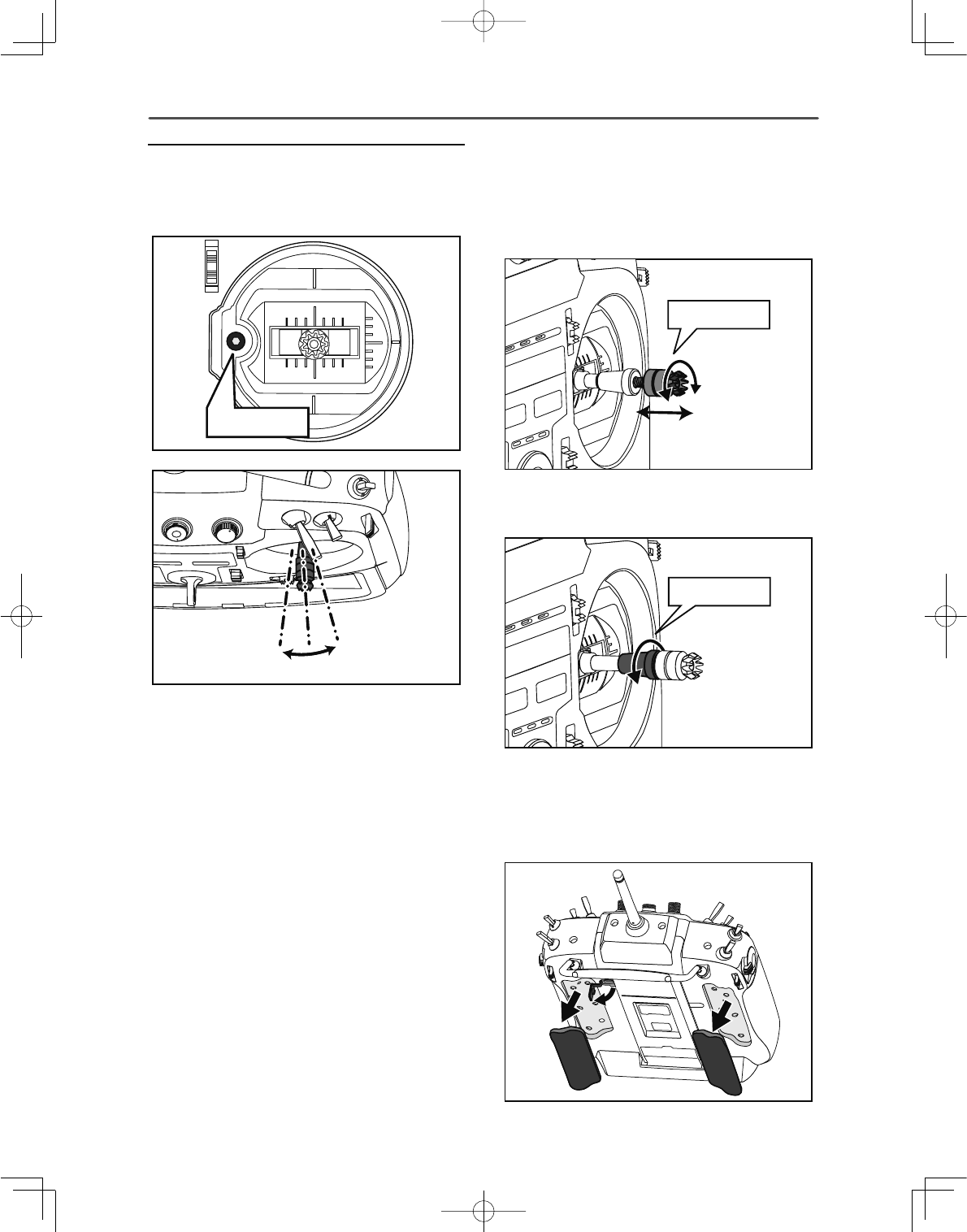
7UDQVPLWWHUFRQWUROV
Cautions on handling antenna
WARNING
Do not touch the antenna during operation.
*There is the danger of erroneous operation causing a crash.
Do not carry the transmitter by the antenna.
*There is the danger that the antenna wire will break and
operation will become impossible.
Do not pull the antenna forcefully.
*There is the danger that the antenna wire will break and
operation will become impossible.
-
-
-
-
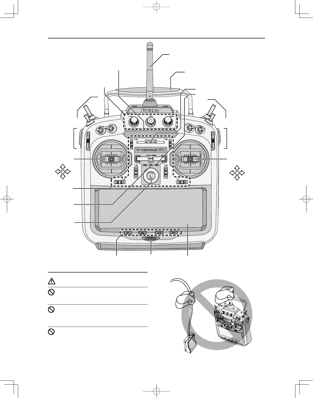
ٴ$QWHQQD
ٴ&DUU\LQJ+DQGOH
ٴ6SHDNHU
ٴ0LFURSKRQH
ٴ6ZLWFK%ORFN
6&6'6*6+
ٴ6OLGH/HYHU
56756
ٴ6WLFN
ٴ5RWDU\.H\ ٴ/&''LVSOD\7RXFK3DQHO
ٴ'LUHFW.H\
66
ٴ'LJLWDO
7ULP
ٴ+RRN
ٴ3RZHU
6ZLWFK
77
ٴ6WLFN
ٴ6OLGH
/HYHU
/6/67
ٴ6ZLWFK%ORFN
6$6%6(6)
ٴ9ROXPH
/'&'5'
ٴ0RQLWRU/('
15
<Before Use >
•Rotating antenna
7KHDQWHQQDFDQEHURWDWHGGHJUHHVDQGDQJOHG
degrees. Forcing the antenna further than this can
damage it. The antenna is not removable.
180°
90°
•Angle adjustment of the antenna
The antenna rotation and angle can be adjusted. The
antenna features weak radio waves in the forward
direction and strong radio waves in the sideways
directions. Adjust the antenna angle to match your
À\LQJVW\OH
LED monitor
The status of the transmitter is displayed by changing
the “MONITOR” section LED.
(LED Display)
◆FASSTest mode → Light Blue light
◆FASST mode → Green light
◆S-FHSS/T-FHSS mode → yellow-green light
◆RF-OFF → Violet light
◆Starting → Red light
◆Trainer Student → Blue light
Switch reallocation
You can reallocate the toggle switches on the
shoulders of the transmitter, as you like.
(Default settings)
• SA : 3 positions; Alternate; Short lever
• SB : 3 positions; Alternate; Long lever
• SC : 3 positions; Alternate; Long lever
• SD : 3 positions; Alternate; Short lever
• SE : 3 positions; Alternate; Short lever
• SF : 2 positions; Alternate; Long lever
• SG : 2 positions; Alternate; Short lever
• SH : 2 positions; Momentary; Long lever
*You can choose the Switch and the On/Off position in the
Switch Selection menu of your mix.
•When you change switches:
To relocate switches;
1. Make sure your transmitter is off, and use
the attached 2.5mm hexagonal wrench
(included) to turn the screw counter-clockwise
on the switch block and detach the block.
Remove the screw holding the switch block.
Pull up on the switch block to remove it.
2. Disconnect the connectors of switches you
want to change.
3. Use the attached jig (inside stylus) to turn the
/RZSRZHU
+LJKSRZHU +LJKSRZHU
16 <Before Use >
face nuts counterclockwise, this will detach
the switches.
4. To re-attach, use the face nuts to attach
switches from other positions or optional
switches to the switch block.
5. Connect your connectors.
6. Insert the switch block so reconnect the
connectors that it fits correctly into the body
of the transmitter (as shown in the picture)
and use the hexagonal wrench to tighten the
screws.
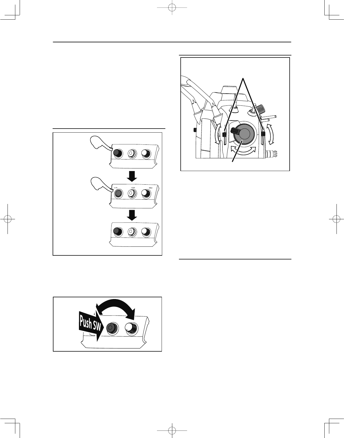
Volume
Pushing down on either
the LD or RD volume
control will lock it in
the down position.
Pushing the volume control
again will release it so that it
can adjusted.
Volume LD, CD, and RD:
If you push the volume button in, it will be locked in
place. To release the volume button, push it in lightly
once more.
This volume is digital type (rotary encoder).
"CD" volume works as both a volume and a push-
switch.
*T18MZ-WC beeps when the volume knob reaches center.
*You can check the volume position on the Dial Monitor screen
in the Linkage menu.
*You can use each setting screen of the mixing functions to
VHOHFWYROXPHVDQGGH¿QHWKHGLUHFWLRQRILWVPRYHPHQW
Slide Lever
Lever LS back and forth
movement linked operation
Lever LST independent operation
LST (Left), RST (Right):
Outside levers
LS (Left), RS (Right):
,QVLGHOHYHUV(DFKOHYHUKDVWZRHQGVRQHDWWKH
front and the other at the back of the transmitter.
*It will beep when the lever is set to the center.
*You can check the lever position on the dial-monitor screen in
the linkage menu.
*You can select a slide lever and set the movement direction on
the setting screen of mixing functions.
Digital trim
This transmitter is equipped with digital trims.
Each time you press a trim button, the trim position
moves one step. If you continue pressing it, the trim
position starts to move faster. In addition, when
the trim position returns to the center, the tone will
change. You can always monitor trim positions
graphics on the screen. To change the trim rate, you
must activate this through the function menu, within
the linkage menu. Touch the trim button and you will
access another screen which enables you to change
the trim percentages.
LD RD
R
o
t
a
r
y
CD
17
<Before Use >
7
7
7
7
77
Note: The trim positions you have set will be stored in the
non-volatile memory and will remain there.
Touch Panel/ Rotary Key/ Direct Key
ٴ5RWDU\.H\
ٴ/&''LVSOD\7RXFK3DQHO
ٴ'LUHFW.H\
66
Touch panel, rotary keys and direct keys are used for
entering data.
Touch Panel
Touch the panel with your finger or the attached
stylus pen, which is also used as a toolbox, to enter
data.
CAUTION
Touch softly the Touch Panel with the stylus pen
RU\RXU¿QJHUWLSV
or
3ODVWLF¿OPLVDWWDFKHGWRWKHWRXFKSDQHO3OHDVHEHFDUHIXOVR
that you don't scratch the touch panel with anything hard such
as a metal object. Don't push the touch panel with excessive
force or drop anything on the panel.
*Although you may find some air bubbles under the plastic
panel due to environmental changes such as temperature, it is
not a defect and will cause no problems.
*Color LED is made from many pixels. Some pixels hold
lighting. Moreover, some pixels go out. And a screen may
ÀLFNHU6XFKFRQGLWLRQLVWKHFKDUDFWHULVWLFVRIFRORU/(',WLV
not failure.
Rotary key
In addition to touch panel, you can select items by
rotating the rotary keys to the left or to the right.
*There is a function which cannot be accessed by the Rotary
Key.
Direct key
You can directly call your favorite functions or menu
screens.
(The default setting at the factory)
S1: System menu
S2: Linkage menu
S3: Model menu
S4: Return
>+RZWRFKDQJHDVVLJQPHQWRIWKHGLUHFWNH\@
1. Open the screen you want to call. Then push
S1 and S4 keys simultaneously. (You will see the
direct key setting screen.)
2. Select the direct key.
3. Press the [Enter] key.
4. Press the [Yes] key.
Touch Panel (and Rotary Key) lock
Please perform a touch-panel lock for safety. Touch
VFUHHQLQ>6\VWHP0HQX@ →>'LVSOD\@RWKHUWKDQWKH
following has an automatic setup.
6WDUWXSORFN,WEHFRPHVDSDQHOORFNDWWKHWLPHRI
the power supply ON.
$XWRPDWLFORFN,WV\QFKURQL]HVZLWK%DFNOLJKW
decrease time and becomes a panel lock.
DANGER
The T18MZ-WC's touch screen is very sensitive.
To avoid accidentally activating it during a
flight, it is suggested that it be locked. Due to
the touch screen's sensitivity, allowing it to be
WRXFKHGGXULQJÀLJKWE\DQHFNVWUDSKRRNVHUYR
extension, or even your hand could be dangerous.
Please use the touch panel lock for added safety
GXULQJÀLJKW
Ɣ'LUHFW.H\
(S2-S3)
7KHtouch panel lockedE\
S2DQGS3SXVKHG
Ɣ'LUHFW.H\
(S2-S3)
7KHtouch panel unlockedE\
S2 DQGS3SXVKHGDJDLQ
Locking the LCD touch screen.
18 <Before Use >
Stick Adjustment
Adjustment of the stick lever angle
<RXFDQPDNH¿QHDGMXVWPHQWVWRWKHDQJOHRIDVWLFN
lever either inwards or outwards from the center
stick position.
ٴ6FUHZ
8VHWKHDWWDFKHGPPKH[DJRQDOZUHQFKLQVLGH
stylus) to turn the screw clockwise to adjust the stick
outwards, or counter-clockwise to tilt it inward.
Note: Be careful not to turn the screw too far counterclockwise
as it could fall out.
Adjustment of the lever length
You can adjust the length of stick levers, if you like.
It is recommended to adjust the length of the sticks
in line with your hand size.
>+RZWRDGMXVWWKH6WLFNOHQJWK@
1. Hold the lever head "B" and turn the lever
head "A" counter-clockwise, the lock will be
released.
2. Adjust the stick lever to the desired length by
turning lever head A.
3. Securely lock the stick lever by holding
lever head A and turning lever head B
counterclockwise.
Adjustment of Stick Lever Tension
You can adjust the tension of stick-levers.
7KHUXEEHUFRYHULQWKHEDFNLVUHPRYHG¿UVW
/HYHUKHDG%
/HYHUKHDG$
19
<Before Use >
ٴ5HWDLQLQJ)RUFH-
0RGH
ٴ6WLFN
7HQVLRQ
-
ٴ6WLFN7HQVLRQ-
0RGH
ٴ6WLFN7HQVLRQ
-
ٴ6WLFN7HQVLRQ-
0RGH
ٴ5HWDLQLQJ
)RUFH-
0RGH
>$GMXVWPHQWRIWHQVLRQ@
Adjustment of Throttle Stick (Ratchet System)
You can choose either airplane ratchet system or
helicopter-touch.
1. Open the dust protection cap on the back of the
transmitter that is covering the hole for throttle stick
adjustment.
2. Use the attached 1.5mm hexagonal wrench (inside
stylus) to turn the adjustment screw and set it as you
prefer. Turning the screw clockwise increases the
tension.
For airplanes: Adjust the screw on the left.
For helicopters: Adjust the screw on the right.
In changing the setting from airplane to helicopter
(or heli to airplane);
1. Turn the screw counter-clockwise until the throttle
stick moves freely, and turn the screw clockwise to
adjust it to the tension you prefer.
*This transmitter has two ratchet plates, one for airplane
and the other one for helicopter. If you tighten both screws,
you won't be able to achieve the adjustment that you need
because of the overlap of those two adjustments.
*If you want to change the setting from airplane to helicopter
(or from helicopter to airplane), turn the ratchet screw
clockwise until the throttle stick moves freely. Then turn the
screw for the helicopter until you get the tension you like.
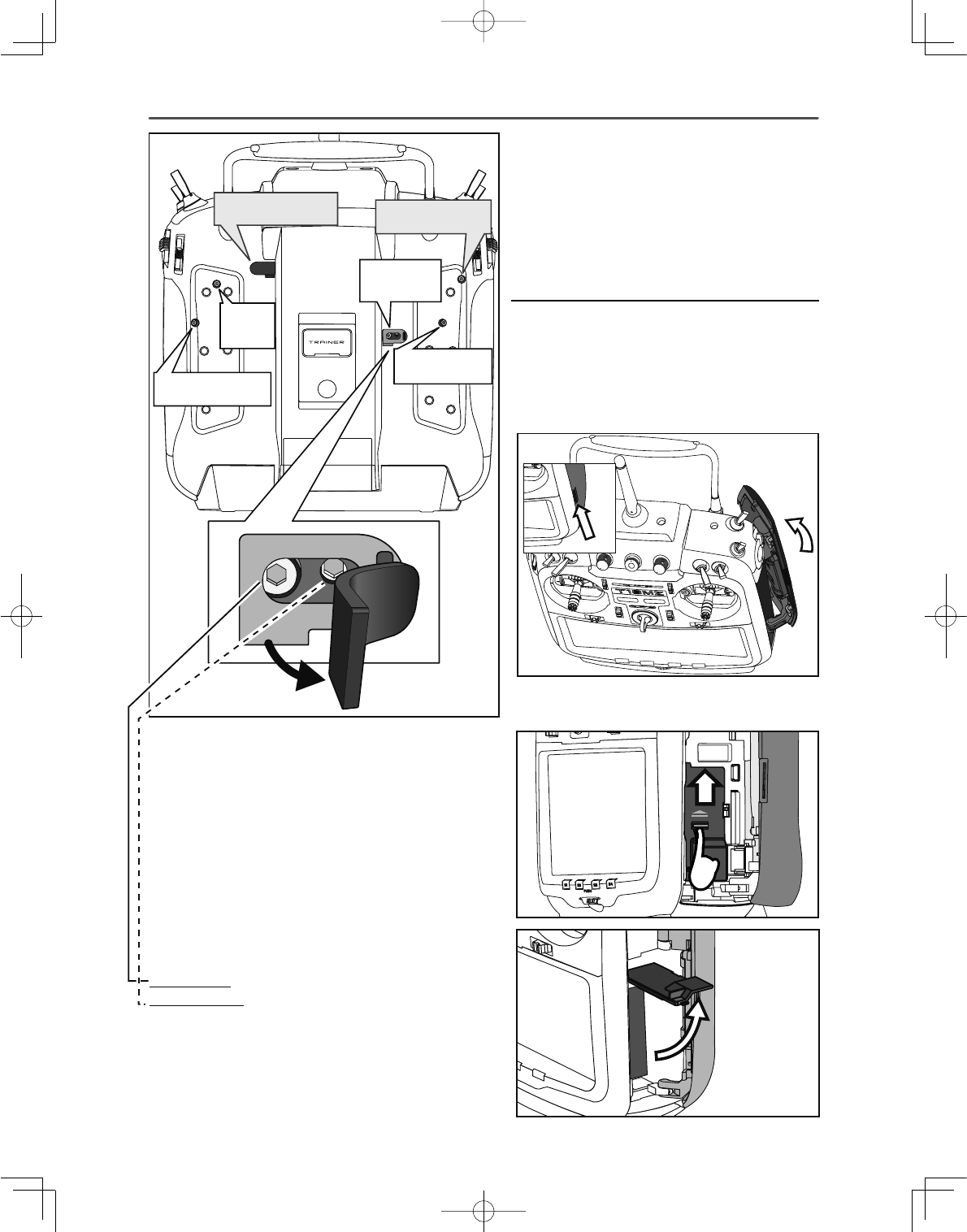
Battery exchange
Note: Detaching the battery while the power is
on can cause data you have recently edited to be
lost.
>+RZWRUHPRYHEDWWHU\/7);+@
1. Using the tabs at the side of the transmitter,
open the side door to the rear as shown in
WKHÀJXUH
2. Open the battery cover inside the transmitter
E\VOLGLQJLWXSZDUGDVVKRZQLQWKHÀJXUH
*In the Mode 1/3, arrangement of a screw is opposite.
20 <Before Use >
*Remove the connector by pulling up on
the lip of the slider, not the wiring.
4. Pull out the battery.
>+RZWRLQVWDOOEDWWHU\/7);+@
1. Insert the battery into the transmitter.
2. Insert the battery with the battery connector
IDFLQJWKHGLUHFWLRQVKRZQLQWKHÀJXUH3XVK
the battery housing, not the battery wiring. )
3. Arrange the battery wiring as shown in the
ÀJXUH
&RQQHFWRUVOLGHU
%DWWHU\FRQQHFWRU
3. Pull up on the lip of the black "connector
slider" to remove the battery connector.
*As for T18MZ-WC, the battery connector is not connected at
¿UVW
3OHDVHFRQQHFWDEDWWHU\FRQQHFWRUDVVKRZQLQD¿JXUH
21
<Before Use >
4. Close the battery cover so that the wiring is
not pinched and lock the cover by pushing
downward.
5. Close the side door.
WARNING
Be careful to not drop the battery.
Never take out the battery from the T18MZ-WC
transmitter while the LED monitor is blinking.
* Internal settings and memories can be destroyed.
* Do not use the transmitter if a “Backup Error” warning oc-
curs. Send it to the Futaba Service Center to be checked.
Don't pull battery wiring.
*When it short-circuits, there is danger of explosion ignition.
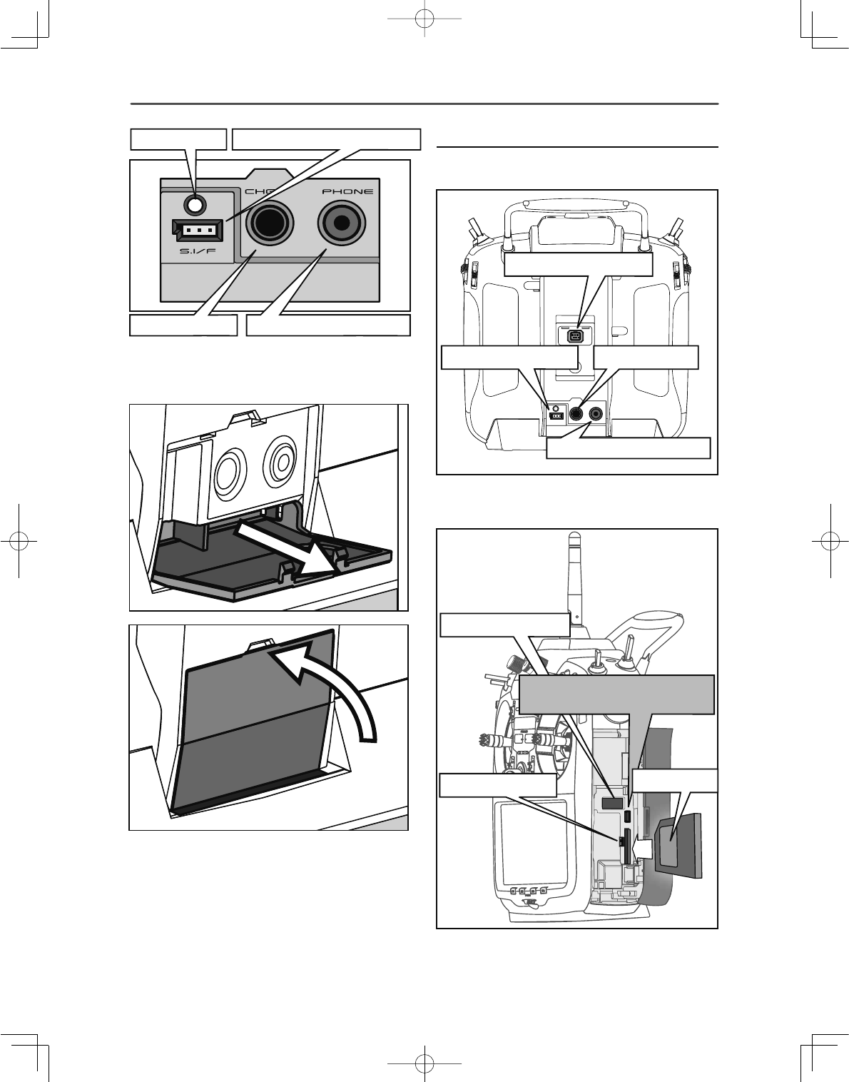
Back lid
The charging connector, earphone jack, S.BUS
setting connector and charge LED are accessed by
opening the transmitter rear cover as shown in the
¿JXUH
>+RZWRRSHQEDFNOLG@
1. Open the transmitter rear cover as shown in
WKHÀJXUH
2. House the rear cover by pushing it into the
transmitter.
22 <Before Use >
Connector/Plug
1. The back of transmitter.
2. Inside of transmitter of side cover
&KDUJH/('
&KDUJHSOXJ $XGLRSOXJ3+21(
6%86VHWWLQJFRQQHFWRU
3. When not using the connector, pull out and
close the rear cover.
.
7UDLQHU&RQQHFWRU
&KDUJH3OXJ
6%86&RQQHFWRU
$XGLRSOXJ3+21(
86%&RQQHFWRU
86%PLQL%&RQQHFWRU
8QXVHG
6'&DUG
8SGDWH6ZLWFK
23
<Before Use >
SD Card (sold separately)
7KH6'FDUGFDQVWRUHYDULRXV¿OHVVXFKDVPRGHO
GDWDPXVLFVRXQG¿OHVDQGSLFWXUHV$Q\6'FDUG
on the market can be used with the T18MZ-WC.
The card is locked when it is pushed in all the way
in. To remove the card, push in on the card again, it
will pop up allowing you to remove it.
*Write protection of SD card is turned OFF. In the state of
protection, model data cannot be saved on SD card.
WARNING
Be sure to turn off the power to the transmitter
before inserting or removing the SD card.
As the SD card is a precision device, do not use
excessive force when inserting.
If model data generated by a new software
version transmitter is copied to an old software
version transmitter, the transmitter may operate
erroneously. Copy the model data after updating
the copy destination transmitter to the new
software version.
Read data from a PC
6DYLQJPXVLFDQGLPDJH¿OHVHGLWHGE\D3&LQWRWKH
SD card, you can use those files on your T18MZ-
WC transmitter. Equipment for reading and writing
SD cards are available at most electronics stores.
Stored data
The life of the SD card is limited due to the use
of flash memory. If you have a problem saving or
reading data such as picture data after a long period
of use you may need to purchase a new SD card.
*We are not responsible for, and cannot compensate for any
failure to the data stored in the memory card for any reason.
Be sure to keep a backup of your models and data in your SD
card.
*No need for backup battery; T18MZ-WC transmitters and
SD cards are using nonvolatile memory devices so that the
data stored in those will not be destroyed even without a
backup battery. The clock for the transmitter depends on the
Lithium battery.
Update Switch
When using an SD card to update the T18MZ-WC
software, set this switch to the up position. Then
input the software to be updated to the SD card
from the Futaba importers homepage and update the
software in accordance with the updating procedure.
USB port
The following functions can be used with USB
connector.
• USB Mouse
When a mouse is connected, a cursor will
appear on the screen and the mouse can be
used instead of the touch panel.
• USB Keybord
When a keyboard is connected, the model
name and other data can be input by
keyboard.
• USB Memory
All model data, etc. can be saved to an
optional USB Memory stick.
Connector for trainer function (TRAINER)
When you use trainer function, connect the optional
trainer cable between the transmitters for teacher and
student.
*You can set the trainer function on the Trainer Function screen
in the system menu
Connector for DSC function (DSC)
You can operate the transmitter without transmitting
radio waves by connecting the transmitter and the
receiver to the DSC cable.
*Please refer to the section "Connection between Receiver/
Servo"
S.BUS connector (S.I/F)
When setting an S.BUS servo and telemetry sensor,
connect them both here.
(Supply power by 3-way hub or 2-way cord.)
Audio plug (PHONE)
Connecting a stereo headphone to this plug, you can
HQMR\PXVLF¿OHVVWRUHGLQWKH6'FDUG
Connector for battery charger (CHG)
You cannot use the charger that was included with
the transmitter, without using the AC adapter that
comes with this.
DANGER
Do not connect any other chargers. The charger
for the receiver battery cannot be used for the
transmitter.
USB port (mini-B)
*This is for factory use only.
24 <Before Use >
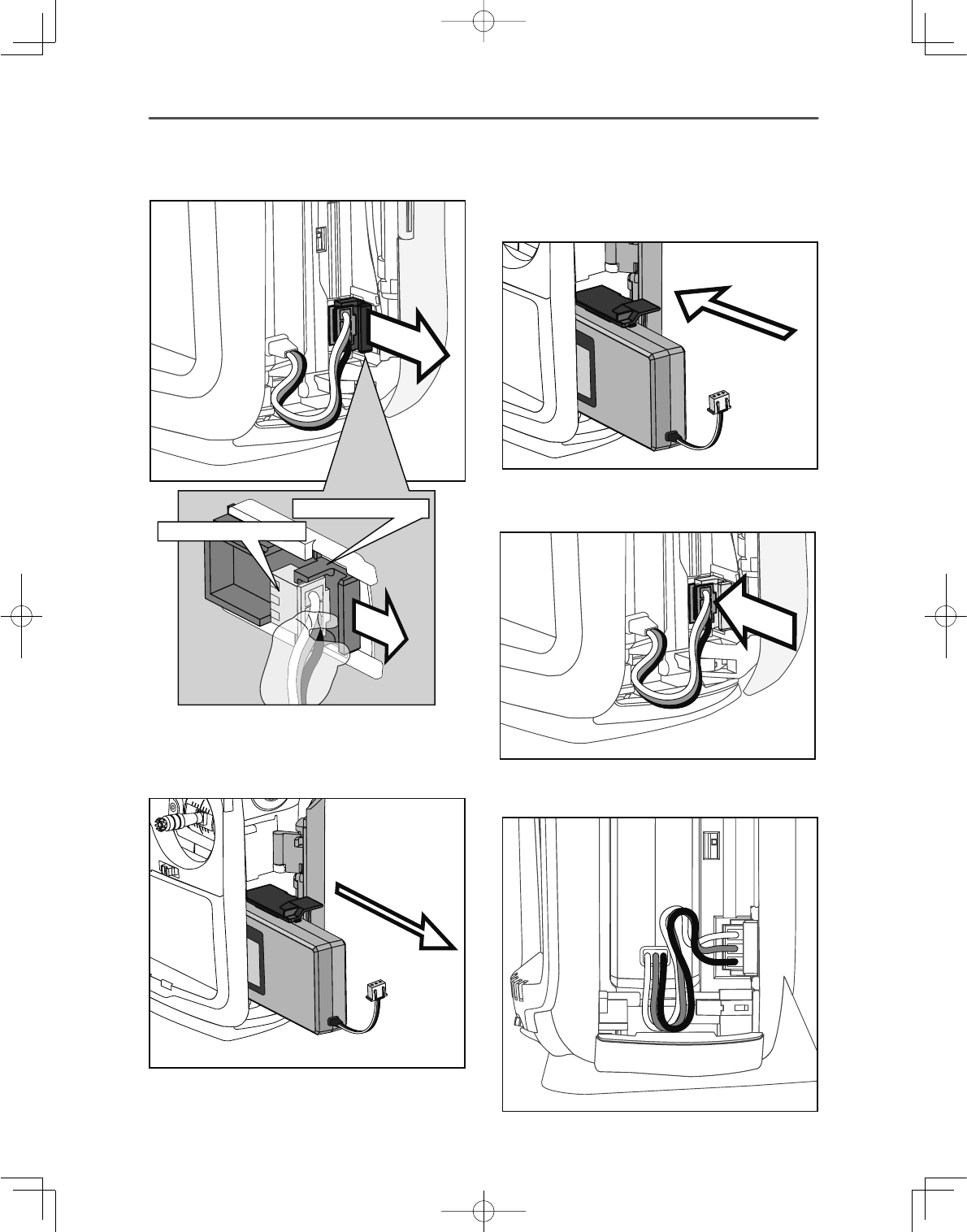
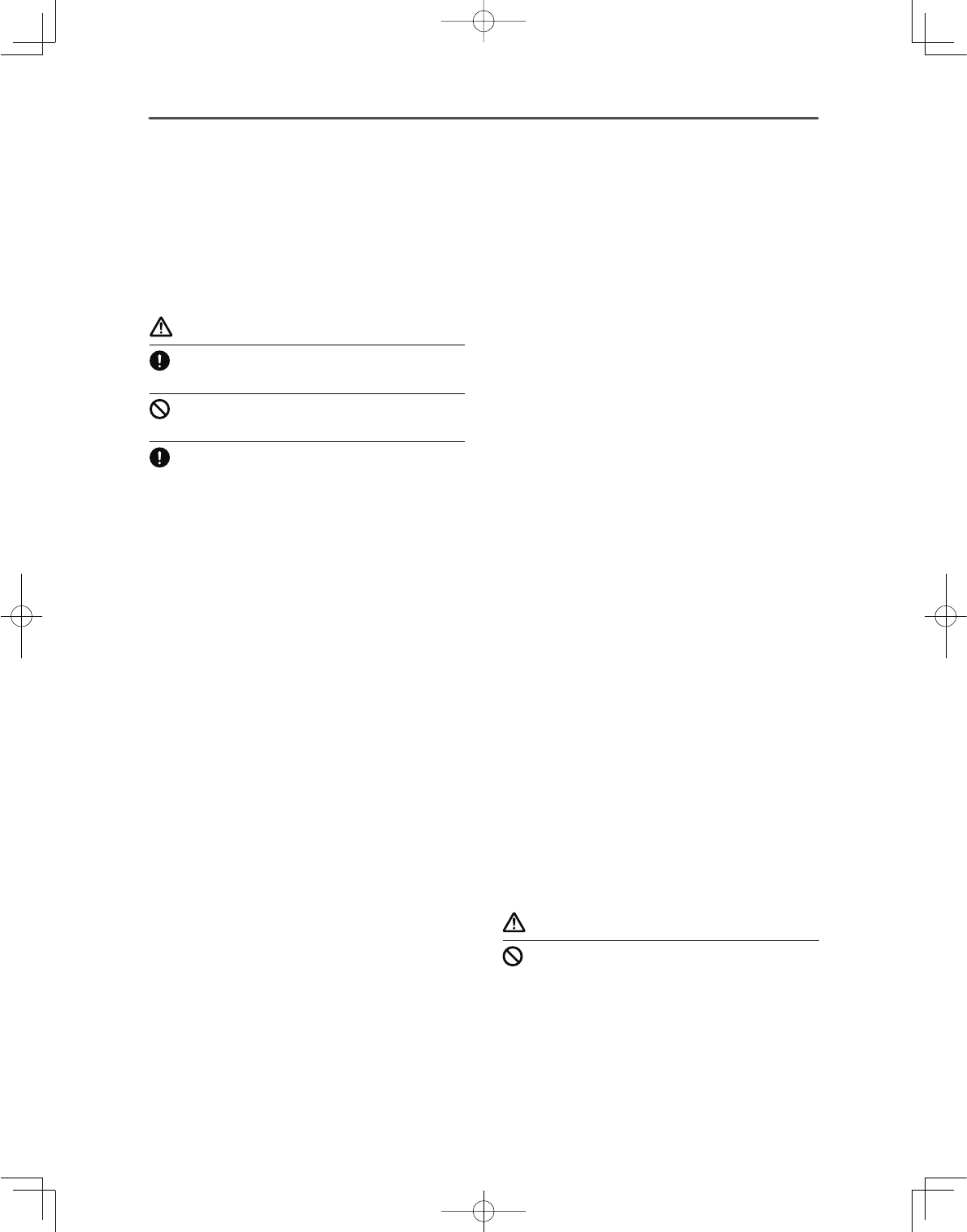
Camera function
This transmitter has a digital camera function. A
picture of your favorite model and other pictures
(0.03M megapixels) can be allocated to transmitter
model data.
&DPHUD
WARNING
'RQRWXVHWKHFDPHUDIXQFWLRQGXULQJÀLJKWDQG
when starting the engine.
*It is dangerous to look away from or have your model out of
\RXUOLQHRIVLJKWZKLOHÀ\LQJ
25
<Before Use >
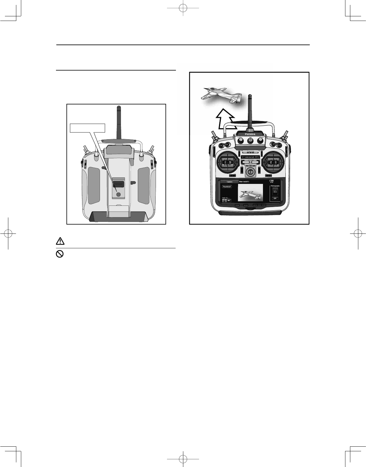
Link/Mode Switch
Use the small plastic screw driver that was included
with your receiver.
The Link/Mode Switch is also used for the CH
mode selection.
(The button is not used to link the transmitter and
receiver together. )
Extra Voltage Connector
Use this connector when using a voltage telemetry
device to send the battery voltage (DC0 ~ 70V)
from the receiver to the transmitter.
Please use an option is External voltage input cable.
Wire in an extra connector to you drive batteries
that mates with the extra voltage connector.
DANGER
Don't touch wiring.
* There is a danger of receiving an electric shock.
Do not short-circuit the battery terminals.
* A short circuit across the battery terminals may cause
DEQRUPDOKHDWLQJ¿UHDQGEXUQV
Please double check your polarity ( + and -)
when hooking up your connectors.
* If + and - of wiring are mistaken, it will damage, ignite and
explode.
'RQ¶WFRQQHFWLRQWR([WUD9ROWDJHEHIRUH
turning on a receiver power supply.
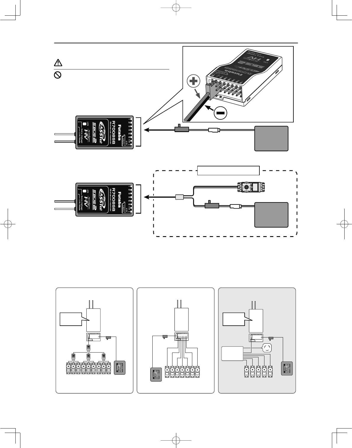
5HFHLYHUQRPHQFODWXUH
Before using the receiver, be sure to read the
precautions listed in the following pages.
Receiver R7008SB
Connector
WKURXJKRXWSXWVIRUWKHFKDQQHOVWKURXJK
%RXWSXWVRIFKDQQHOVDQGSRZHU
6%RXWSXWVRIFKDQQHOVRU6%86SRUW
[S.BUS Sevo S.BUS Gyro ]
6%86RXWSXWVRI6%86SRUW
[Telemetry Sensor ]
:KHQXVLQJRUPRUHFKDQQHOVXVHDQ6%XV
function or use a second R7008SB and link both
to your transmitter.
Connector insertion
Firmly insert the connector in the direction shown
LQWKH¿JXUH,QVHUWWKH6%86E\WXUQLQJLW
degrees.
WARNING
S.BUS2 connectors
Don't connect an S.BUS servo / gyro to BUS2
connector.
LED Monitor
This monitor is used to check the CH mode of the
receiver.
Channels 1 ∼ 6
Channel 7 / Battery
Channel 8 or S.BUS S.BUS2 : Telemetry sensor
or S.BUS2 equipment
+−
26 <Before Use >
Connection of a receiver battery
Connection example
Battery
3.7 ∼ 7.4V
Switch
Servo
Y-harness
When all ports are used.
Battery
3.7 ∼ 7.4V
Switch
A battery is connectable
also with which port.
&KDQQHO
56%
&RQYHQWLRQDOVHUYRV
%DWWHU\
6ZLWFK
3:0
56%
%DWWHU\
+8%
6%86VHUYRV
&KDQQHO
6ZLWFK
WR6%SRUW
6%86
&+0RGH
ڀ0RGH%
56%
%DWWHU\
$LOHURQ3LWFK5XGGHU
(OHYDWRU7KURWWOH
6ZLWFK
&*<*\UR
&*<
*\UR
&+0RGH
ڀ0RGH%
WR6%SRUW
WARNING
Please make sure that you use a battery that can
deliver enough capacity for the number and kind
of servos used. Alkaline (Dry) batteries cannot
be used.
27
<Before Use >
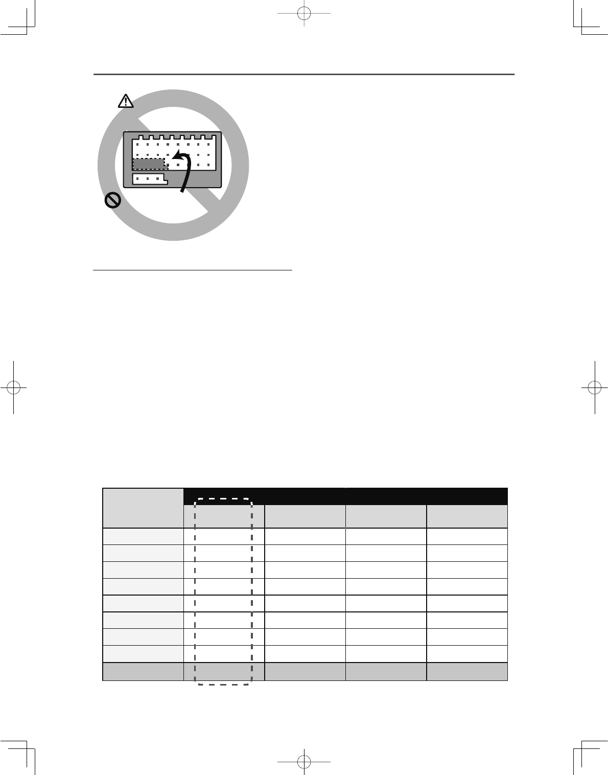
R7008SB CH Mode
The R7008SB receiver is a very versatile unit. It
has 8 PWM outputs, S.BUS and S.BUS2 outputs.
Additionally the PWM outputs can be changed from
FKDQQHOVWRFKDQQHOV,I\RXRQO\GHVLUHWR
use it as an 8 channel receiver (without S.BUS), it
can be used without any setting changes.
The T18MZ-WC has the ability to link to two
R7008SB receivers - one of them outputting
FKDQQHOVDQGWKHRWKHURXWSXWWLQJFKDQQHOV
giving you 16 PWM channels. Instructions for this
FRQ¿JXUDWLRQDQG6%86RSHUDWLRQIROORZ
>+RZWRFKDQJHWKH56%&KDQQHOPRGH@
1. Press and hold down the Link/Mode button on
the R7008SB receiver.
2. Turn the receiver on while holding down the
Link/Mode button. When the LED begins to
blink green/red the button may be released.
3. The LED should now be blinking red in one of
the patterns described by the chart below.
4. Each press of the Mode/Link button advances
the receiver to the next mode.
5. When you reach the mode that you wish to
operate in, press and hold the Mode/Link
button for more than 2 seconds.
6. Once locked into the correct mode the LED
will change to a solid color.
7. Please cycle the receiver(s) power off and
back on again after changing the Channel
Mode.
Receiver
connector
Setting channel
Mode A
1 ∼ 8CH Mode B
1 ∼ 7CH Mode C
9 ∼ 16CH Mode D
9 ∼ 15CH
11199
2 2 2 10 10
3 3 3 11 11
4 4 4 12 12
5 5 5 13 13
6 6 6 14 14
7/B 7 7 15 15
8/SB 8 S.BUS 16 S.BUS
Red LED blink 1 time 2 times 3 times 4 times
56%&+02'(7$%/(
Don't connect neither a switch
nor a battery in this way.
* It will short-circuit, if it connects in this way.
A short circuit across the battery terminals may
cause abnormal heating, fire and burns.
5HFHLYHU
DANGER
Default
28 <Before Use >
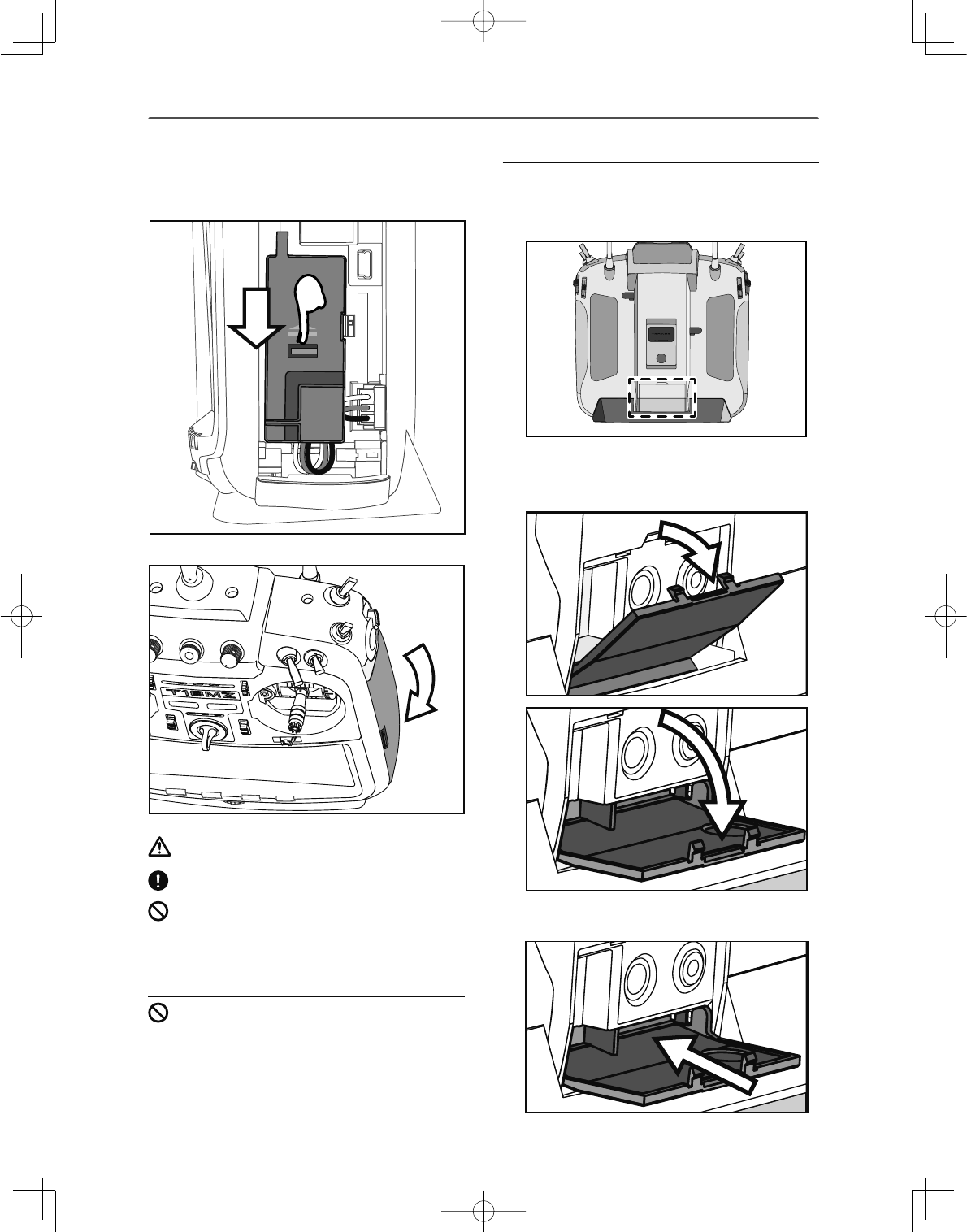
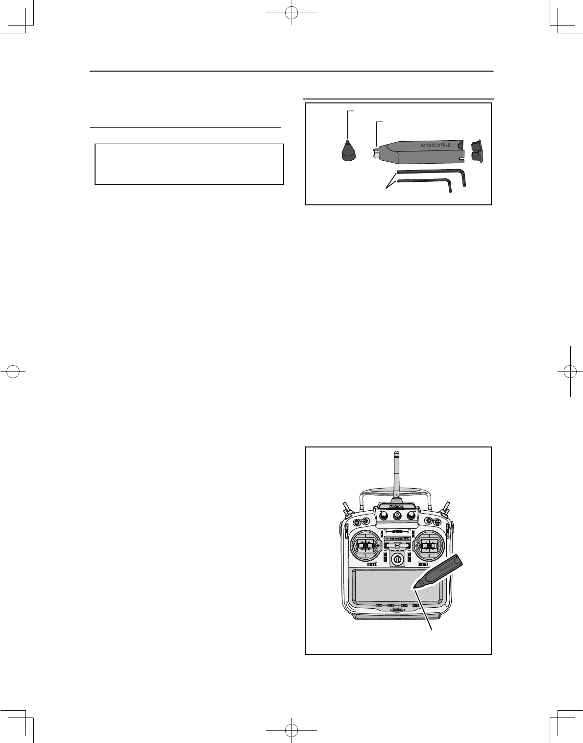
Toolbox
ٴ7RROIRUUHPRYLQJ
GHFRUDWLRQQXWV
ٴ+H[:UHQFKPPDQGPP
ٴ5XEEHU&DS
A special toolbox is included with your T18MZ-
WC. This allows you to make all of the mechanical
adjustments that may be needed.
Hexagonal wrench (1.5mm and 2.5mm)
These wrenches are for adjustment of sticks and
replacement of the switches.
Tool for removing switch nuts.
This is used when changing or replacing switches.
Stylus pen
A rubber cap is attached to the stylus pen/toolbox.
You may use this stylus with rubber cap when
operating the touch panel. The stylus allows more
precise operation than fingers without fear of
damaging the panels surface.
ٴ<RXPD\XVHWKLVWRRO
DVDVW\OXVSHQ
6HUYR2SWLRQ・7RROER[
Servo (Option)
Purchase servos appropriate for their intended use.
*Analog servos may not be used when operating in the
FASSTest 12CH mode.
When operating in the FASSTest12CH mode use digital
servos, this includes all brushless and S.Bus servos.
29
<Before Use >
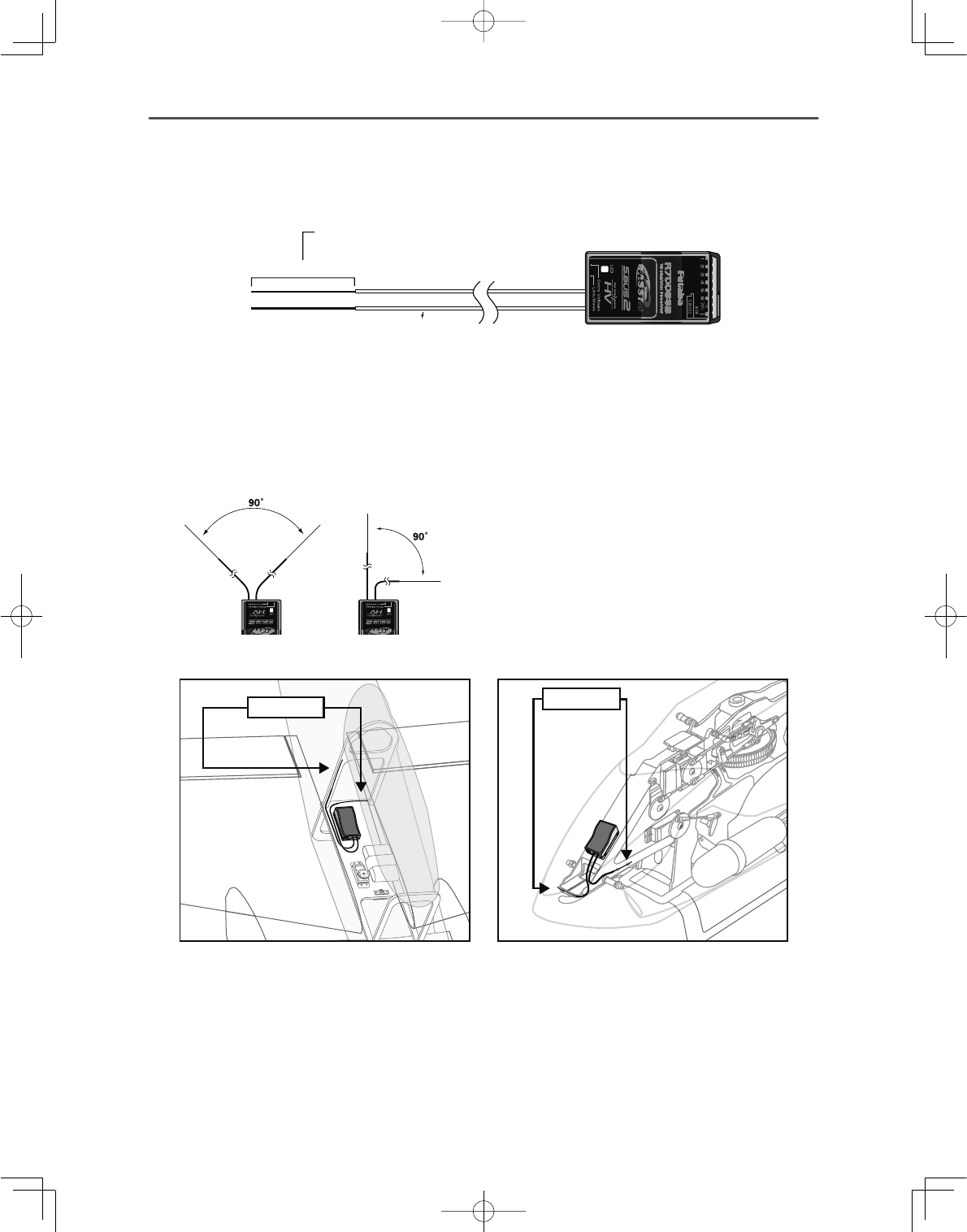
5HFHLYHUV$QWHQQD,QVWDOODWLRQ
The R7008SB has two antennas. In order to maximize signal reception and promote safe modeling Futaba
KDVDGRSWHGDGLYHUVLW\DQWHQQDV\VWHP7KLVDOORZVWKHUHFHLYHUWRREWDLQ5)VLJQDOVRQERWKDQWHQQDVDQGÀ\
problem-free.
$QWHQQD
0XVWEHNHSWDVVWUDLJKWDVSRVVLEOH
&RD[LDOFDEOH
56%5HFHLYHU
To obtain the best results of the diversity function,
SOHDVHUHIHUWRWKHIROORZLQJLQVWUXFWLRQV
1. The two antennas must be kept as straight as
possible. Otherwise it will reduce the effective
range.
2. The two antennas should be placed at 90
degrees to each other.
This is not a critical figure, but the most
important thing is to keep the antennas
away from each other as much as possible.
Larger models can have large metal objects
that can attenuate the RF signal. In this case
the antennas should be placed at both
sides of the model. Then the best RF signal
FRQGLWLRQLVREWDLQHGDWDQ\Á\LQJDWWLWXGH
3. The antennas must be kept away from
conductive materials, such as metal, carbon
and fuel tank by at least a half inch. The
coaxial part of the antennas does not need
to follow these guidelines, but do not bend it
in a tight radius.
4. Keep the antennas away from the motor,
ESC, and other noise sources as much as
possible.
7KHWZRDQWHQQDVVKRXOGEHSODFHGDWGHJUHHVWRHDFKRWKHU
*The Illustration demonstrates how the antenna should be placed.
5HFHLYHU9LEUDWLRQDQG:DWHUSURR¿QJ7KHUHFHLYHUFRQWDLQVSUHFLVLRQHOHFWURQLFSDUWV%HVXUH
to avoid vibration, shock, and temperature extremes. For protection, wrap the receiver in foam
rubber or other vibration-absorbing materials. It is also a good idea to waterproof the receiver
by placing it in a plastic bag and securing the open end of the bag with a rubber band before
wrapping it with foam rubber. If you accidentally get moisture or fuel inside the receiver, you
may experience intermittent operation or a crash. If in doubt, return the receiver to our service
center for service.
$QWHQQD $QWHQQD
30 <Before Use >
Rubber
grommet
Brass eyelet
Wood screw
Servo mount
2.3-2.6mm nut
washer
Rubber
grommet
Brass eyelet
Servo mount
2.3-2.6mm screw
(Helicopter)(Airplane/Glider)
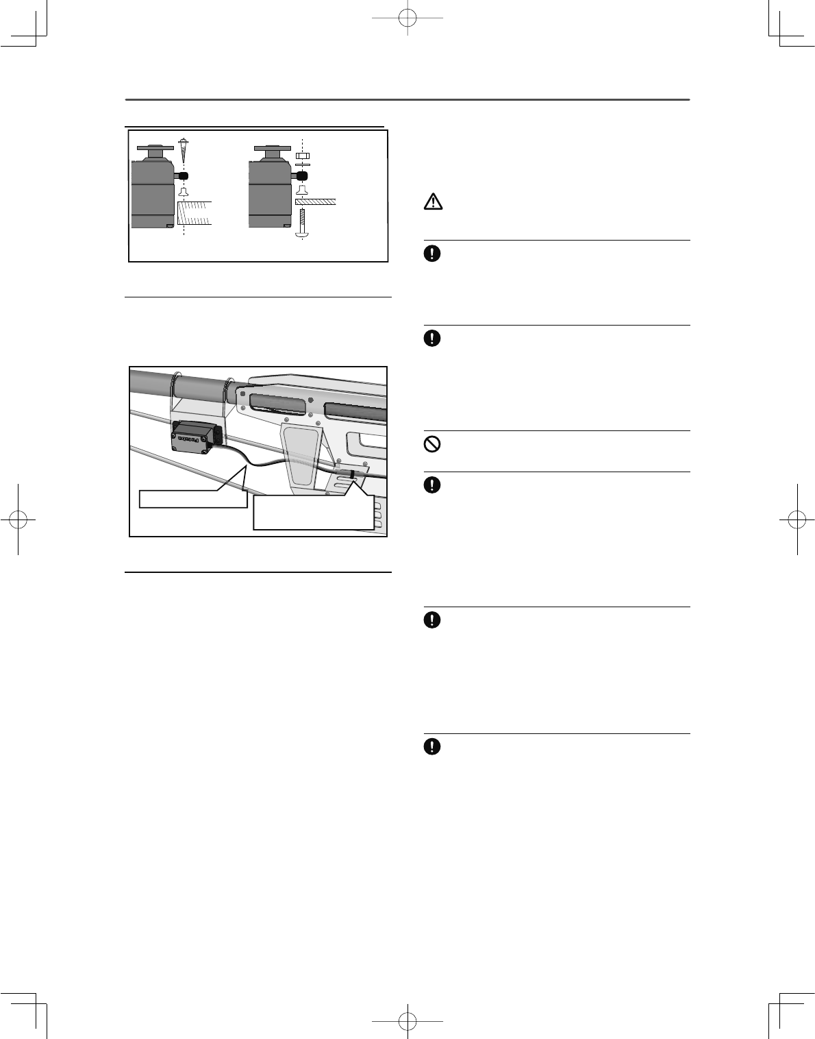
Servo lead wires
To prevent the servo lead cable from being broken
by vibration during flight, provide a little slack in
the cable and fasten it at suitable points. Periodically
check the cable during daily maintenance.
Fasten about 5-10cm
from the servo outlet so
that the lead wire is neat.
Margin in the lead wire.
Mounting the power switch
When mounting a power switch to an airframe, make
a rectangular hole that is a little larger than the total
stroke of the switch so that you can turn the switch
ON/OFF without binding.
Avoid mounting the switch where it can be covered
by engine oil and dust. In general, it is recommended
to mount the power switch on the side of the fuselage
WKDWLVRSSRVLWHWKHPXIÀHU
6DIHW\SUHFDXWLRQVZKHQ
\RXLQVWDOOUHFHLYHUDQG
VHUYRV
WARNING
Connecting connectors
Be sure to insert the connector until it stops at
the deepest point.
How to protect the receiver from vibration and
water
Wrap the receiver with something soft such
as foam rubber to avoid vibration. If there is a
chance of it getting wet, put the receiver in a
waterproof bag or balloon to avoid water.
Receiver's antenna
Never cut the receiver's antenna. Do not bind the
receiver's antenna with the cables for servos.
Locate the receiver's antenna as far as possible
IURPPHWDOVRUFDUERQ¿EHUFRPSRQHQWVVXFKDV
frames, cables, etc.
*Cutting or binding the receiver's antenna will reduce the radio
reception sensitivity and range, and may cause a crash.
Servo throw
Adjust your system so that pushrods will not
bind or sag when operating the servos to the full
extent.
*If excessive force is continuously applied to a servo, the
servo could be damaged due to force on the gear train and/or
power consumption causing rapid battery drain.
Mounting servos
Use a vibration-proof rubber (such as rubber
grommet) under a servo when mounting the
servo on a servo mount. And be sure that the
servo cases do not touch directly to the metal
parts such as servo mount.
*If the servo case contacts the airframe directly, vibration will
travel to and possibly damage the servo.
Mounting the Servo
31
<Before Use >
6%86,QVWDOODWLRQ
7KLVVHWXVHVWKH6%86V\VWHP7KHZLULQJLVDVVLPSOL¿HGDQGFOHDQPRXQWLQJDVSRVVLEOHHYHQZLWKPRGHOV
that use a large number of servos. In addition, the wings can be quickly installed to the fuselage without any
erroneous wiring by the use of only one simple wire, even when there are a large number of servos used.
Ɣ:KHQXVLQJ6%86VSHFLDOVHWWLQJVDQGPL[HVLQ\RXUWUDQVPLWWHUPD\EHXQQHFHVVDU\
Ɣ7KH6%86VHUYRVDQG6%86J\URVPHPRUL]HWKHQXPEHURIFKDQQHOVWKHPVHOYHV6HWWDEOHZLWKWKH70=
WC)
Ɣ7KH6%86V\VWHPDQGFRQYHQWLRQDOV\VWHPUHFHLYHUFRQYHQWLRQDO&+XVHGFDQEHPL[HG
Receiver: R7008SB
Battery: FR2F1800 ( Optional )
Switch: ESW-1J
Throttle servo: BLS173SV ( Optional )
Aileron servo: BLS174SV×2 ( Optional )
Elevator servo: BLS173SV×2 ( Optional )
Rudder Servo: BLS175SV×1 ( Optional )
HUB×3 ( Optional )
HUB ( Optional )
S.BUS Glider usage example
S.BUS Aerobatic plane usage example
Receiver: R7008SB
Servo: S3173SVi×9(Optional )
i-Connector ( Optional )
32 <Before Use >
6%86:LULQJH[DPSOH
%DWWHU\
%DWWHU\
6%86
([WHQVLRQ
FRUG
6ZLWFK
7HUPLQDOER[
+8%
+8% +8%
+8% +8%
+8%
+8%
ق$QRWKHUSRZHUVXSSO\ك
+8%
ق$QRWKHUSRZHUVXSSO\ك
6%866HUYR
6%866HUYR
Receiver
●S.BUS Servo
Since the channel number is memorized by the
S.BUS itself, any connector can be used. When the
SBD-1/SBD-2 (sold separately) is used, ordinary
servos can be used with the S.BUS system.
*SBD-1 cannot be used by S.BUS2 port.
●When separate power supply used
When a large number of servos are used or
when high current servos are used, the servos
can be driven by a separate power supply by
using a separate Power Supply 3-way Hub.
●7HUPLQDOER[
Four connectors can be inserted
Three connectors can be
inserted.
Used when using a separate
power supply battery.
6%86
3RUW
6%
Orange
Green
*When using 8/SB as S.BUS, you have to set CH
MODE of the mode B or mode D.
WARNING
Power supply
Please make sure that you use a battery
that can deliver enough capacity for
the number and kind of servos used.
Alkaline batteries cannot be used.
33
<Before Use >
6%86GHYLFHVHWWLQJ
S.BUS servos or a telemetry sensor can be connected directly to the T18MZ-WC. Channel setting and other
data can be entered for the S.BUS servos or sensors.
3-way hub
or 2-way
6%866HUYR
6%86GHYLFH
WHOHPHWU\VHQVRU
5HFHLYHUV
%DWWHU\
70=:&
1. Connect the S.BUS device and battery you
want to set with a 3-way hub or 2-way cord
DVVKRZQLQWKHÀJXUH
2. Turn on the transmitter power.
3. Call the setup screen.
Servo: System Menu → S.BUS Servo
Sensor: Linkage Menu → Sensor
4. Perform setting in accordance with each
screen.
5. This sets the channel and other data for each
S.BUS servo, or telemetry device to be used
with the S.BUS device or receiver.
6%866\VWHP
When using the S.BUS2 port, an impressive array of telemetry sensors may be utilized.
Receiver port S.BUS Servo
S.BUS Gyro S.BUS2 Servo
S.BUS2 Gyro Telemetry
sensor
S.BUS ○○×
S.BUS2 × (※) ○ ○
6%867$%/(
(※)'RQWFRQQHFW6%866HUYR6%86
*\URWR6%86FRQQHFWRU
6%86
3RUW
6%86
3RUW
6%
+XE
+XE +XE +XE
5XGGHU6HUYR
6%866HUYR6%866HUYR
6%86VHUYR
&RQQHFWLRQLVSRVVLEOH
6%86J\UR
&RQQHFWLRQLVSRVVLEOH
6%86VHUYR
&RQQHFWLRQLVLPSRVVLEOH
7HOHPHWU\VHQVRU
&RQQHFWLRQLVLPSRVVLEOH
6%86
*<52
&+0RGHLVVHW
WR0RGH%>'@
ٔ
7HOHPHWU\
6HQVRU
S.BUS servos and gyros and S.BUS2
servos and gyros must be used in the
correct receiver ports. Please refer to
the instruction manual to make sure
you connect to the correct one.
34 <Before Use >
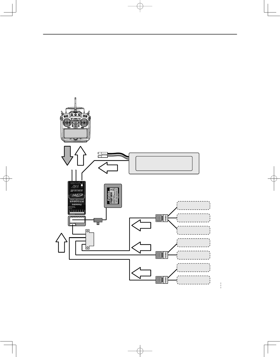
7HOHPHWU\6\VWHP
The R7008SB receiver features bi-directional communication with a FASSTest Futaba transmitter using the
S.BUS2 port. Using the S.BUS2 port an impressive array of telemetry sensors may be utilized. It also includes
both standard PWM output ports and S.BUS output ports.
*Telemetry is available only in the FASSTest 18CH/T-FHSS mode. (FASSTest 12CH mode displays only
Receiver battery voltage and Extra battery voltage.)
*The telemetry function requires the corresponding receiver.
(DFKUHFHLYHUKDVLWRZQXQLTXHJXLGJOREDOO\XQLTXHLGHQWL¿HURU,'FRGHIRUWKHWUDQVPLWWHUWRUHPHPEHU
and recognize when in use.
6%86
&RQQHFWRU
7HPSHUDWXUH
6HQVRU Slot 1
Slot 2
Slot 3 ∼ 5
Slot 6 ∼ 7
Slot 8 ∼ 15
Slot 16
Receiver
Battery voltage is
displayed at the transmitter.
Power battery voltage is
displayed at the transmitter.
6ZLWFK
70=:&
7HUPLQDOER[
+8%
+8%
+8%
Info
Info
Info
Info
Info
voltage
Signal
530
6HQVRU
$OWLWXGH
6HQVRU
*36
6HQVRU
Slot 17
Slot 31
6HQVRU
9ROWDJH
6HQVRU
6HQVRU
●Telemetry sensor (sold separately)
Your aircraft's data can be checked in the
transmitter by connecting various telemetry
sensors to the S.BUS2 connector of the
receiver.
●Slot No.
Servos are classified by channel, but
sensors are classified by “slot”. Since the
initial slot number of the T18MZ-WC is
preset at each sensor, the sensors can be
used as is by connecting them. There are 1
31 slots.
Info
35
<Basic Operation >
%$6,&23(5$7,21
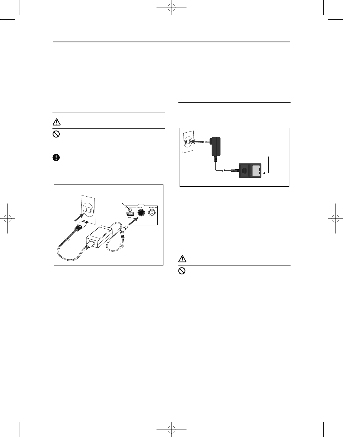
%DWWHU\&KDUJLQJ
Before charging batteries, read the "Cautions for
handling battery and battery charger" in the section
"For your safety".
Charging the transmitter LT2F3500XH lithium-
polymer battery
DANGER
The LT2F3500XH lithium-polymer battery is
for the T18MZ-WC transmitter only. Do not use
it with other devices.
Always use the included AC adapter to charge
the battery.
The charging circuit is built into the T18MZ-WC.
[Method of charging battery]
70=
$&
&KDUJHODPS
1. Turn off the transmitter power.
2. Connect the power plug of the AC adapter
to an 110V outlet.
*Don't connect AC plug to the T18MZ-WC without
connecting with a 110V outlet.
3. Open the back lid of the transmitter and insert
the plug of the AC adapter into the CHG port.
4. The charging monitor of the transmitter lights
red.
*In the case LCD screen will come on for several
seconds and then go off. It may take several
seconds for charging to start after the AC adapter
is connected.
5. When the battery is fully charged the
transmitter monitor will light green. Remove
the charge plug and AC adaptor.
*After using the AC adapter always disconnect the
power cord from the AC outlet.
*The time to charge a completely discharged battery
pack is approximately 2 hours 30 minutes. However,
the actual charging time may vary depending on
temperature and state of the battery.
*If the battery is improperly installed or is faulty, the
transmitter monitor will not light and the battery will
not charge.
How to charge the LiFe battery FR2F1800
(Option) for the receiver
Use the battery charger that is included in the set.
[Method of charging battery]
$&
3S2S
MODEL :
LBC-4E5
Intelligent LiFePO4 for 2S/3S Cells
Balance CHARGER
Red on, green off : Charging
Red flash : Output short-circuit or wrong polarity
Green on, red off : Charging Full
ٴ7KHFRQQHFWRURIWKH
EDWWHU\LVFRQQHFWHGZLWK
6VLGHRIWKHFKDUJHU
ق6VLGHVك
&KDUJHU/%&(
1. Connect the power cable of the charger to
the wall socket (AC outlet).
2. Connect the connector to the LiFe battery.
*Confirm that the red LED charging indicator lights
are on.
3. Remove the battery after the LED light turns
green.
*After completing the charge remove the battery
from the charger and remove the charger from the
wall outlet.
WARNING
The transmitter battery cannot be charged with
the receiver charger. Conversely the receiver
battery cannot be charged with the transmitter
charger.
36 <Basic Operation >
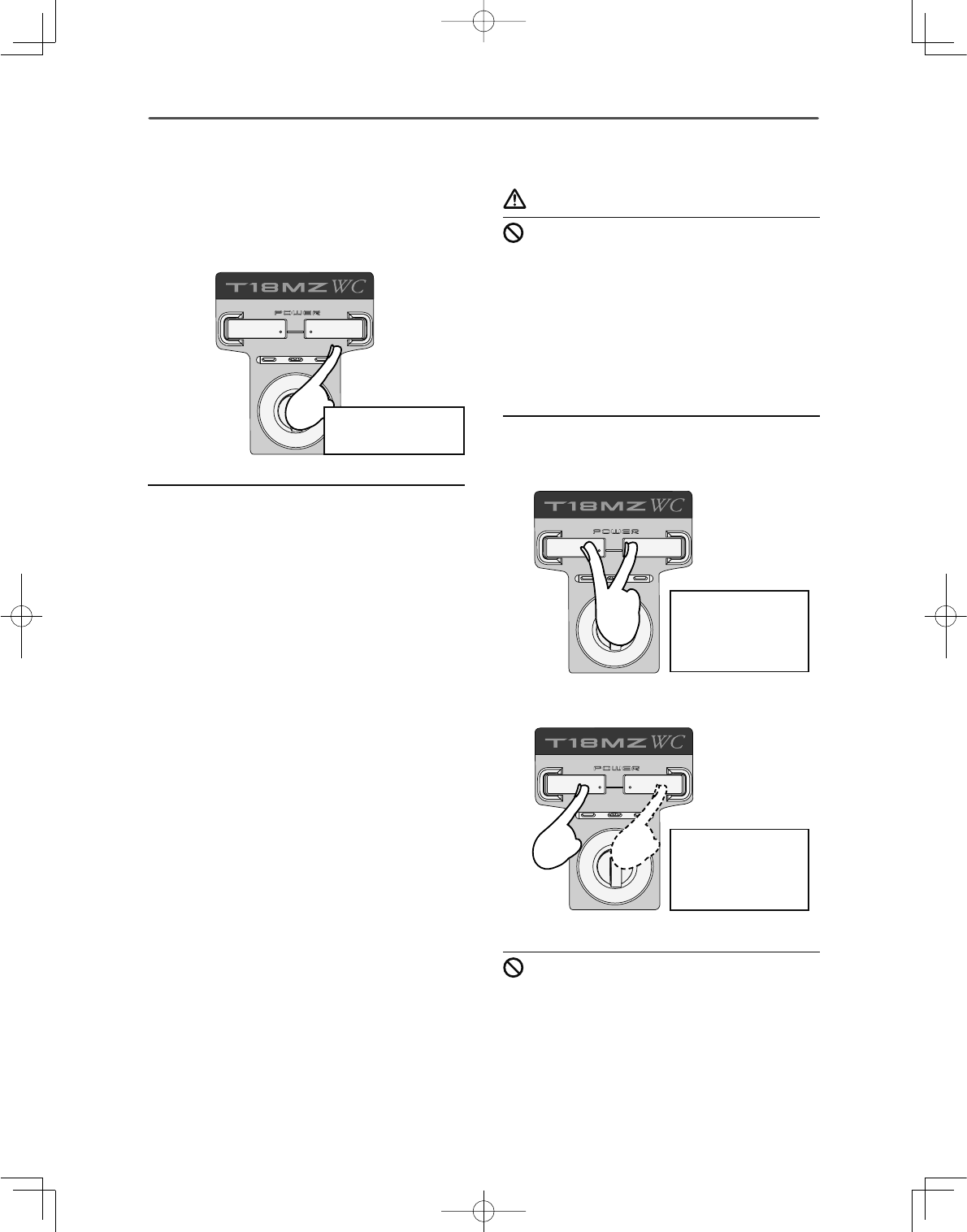
+RZWRWXUQ212))WKH
SRZHURIWKHWUDQVPLWWHU
Windows® CE is installed as a built-in operating
system in the T18MZ-WC transmitter. Compared to
the conventional system, the T18MZ-WC takes extra
time for internal processing when it is turned on/off.
When turning on the power of the transmitter
1. Place the throttle stick below 1/3 closed.
2. Turn on the power switch.
*After initialization of the transmitter is complete, the
LED monitor turns Purple.
*If your throttle stick is not at 1/3 closed or fully
closed, a warning will sound. If you move the
throttle to 1/3 closed or fully closed, the warning will
stop and will become a "Transmit ?" screen.
*If you push the button "NO", then the transmitter will
not emit radio waves.
*If you push the button "Yes", then the transmitter will
emit radio waves.
*If a battery is removed and it re-connects, please
switch on a power supply, after 3 seconds or more
pass.
Start-up time;
The time required to initialize the internal circuit
of the transmitter varies between the previous time
you turned the power off and then restarted the
transmitter. There are two “start up” modes for your
transmitter, see below:
Cold start;
If you turn on the transmitter more than four hours
after you last turned it off, the mode is “Cold start”.
³&ROGVWDUW´LVQRUPDOIRUWKH¿UVWLQLWLDOSRZHUXSRI
the day. It will take about 30 seconds to be ready for
use, as it takes time to initialize the internal circuit of
the transmitter.
Hot start;
If you turn on the transmitter less than four hours
after you last turned it off, the mode is “Hot start”.
Since initialization has been partly completed, the
transmitter will be ready to use in several seconds.
³+RWVWDUW´WDNHVSODFHXVXDOO\DWDVHFRQGÀLJKWRU
ODWHUÀLJKWLQWKHGD\
WARNING
Once you turn on the power, never shut off the
power switch until the power becomes stable (or
until the first screen shows up). If you turn off
the power switch while the transmitter is going
through the initialization process, the data could
be damaged.
Note: The start-up time may be a little bit
slower when the SD card is installed compared
to when the card is not.
How to stop the transmitter
Turn off the power switch of the transmitter. The
internal circuit of the transmitter starts the shut down
process including saving the set-up data.
Once you turn off the power, never operate the
power switch until the power shutdown process
is fully completed. If you turn on the power
switch again while the transmitter is still in the
process of power shutdown, the data could be
damaged.
7KHULJKWVZLWFK
LVSXVKHG
,WZLOOWXUQRí
E\SXVKLQJERWK
SLHFHV
VLPXOWDQHRXVO\
,WZLOOWXUQLWRí
E\SXVKLQJRQH
VLGHIRUDOHQJWK
RIWLPH
or
37
<Basic Operation >
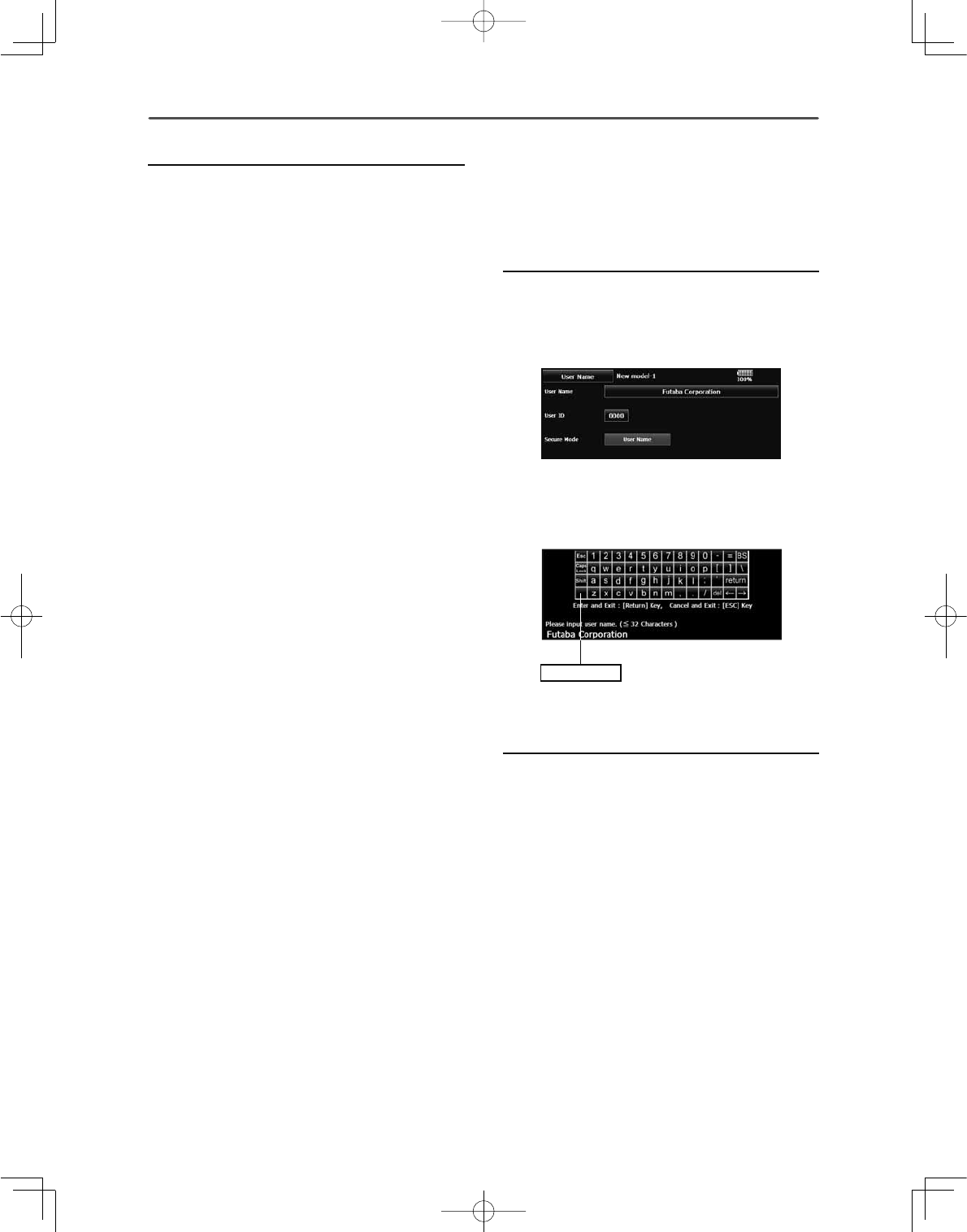
5HJLVWUDWLRQRIWKHXVHUV
QDPH
T18MZ-WC transmitter can register user's name.
How to register user's name
1. Turn on the power of the transmitter.
2. Push the area of the user's name shown on the
home screen or the "user's name" in the system
menu. Then the User's Name Set screen will
pop up.
3. Push the user's name. Then the keyboard will
pop up. You can use up to 32 characters as a
user's name. Use the keyboard on the screen
to enter user's name.
6SDFHNH\
4. Push "Return" key to return to the previous
screen after entering the user's name.
(If you want to protect the user's name)
If you don't want anybody else to change your user's
name, set your ID in the following way.
*Please be aware that you will not able to change user's name if
you forget your password.
1. Make sure that the security mode is "User's
name", and then push the User ID button.
2. Enter your password, using keyboard on the
screen. You will need to enter your password
for changing the user's name, the next time
you turn on the power.
*Even if you enter the same character, your
SDVVZRUGZLOOEHLGHQWLÀHGGLIIHUHQWO\GHSHQGLQJRQ
whether you are using "Transform" mode or "Direct"
mode for inputting.
How to reset software
If the screen freezes for some reason and you cannot
edit, the transmitter power supply is not fully off
even if you turn OFF the power switch. You will
need to remove the battery and reinsert it again. In
this case, the power restarts in “Cold mode”. Even
though the screen freezes, all the other functions for
radio control operation remain operative.
38 <Basic Operation >
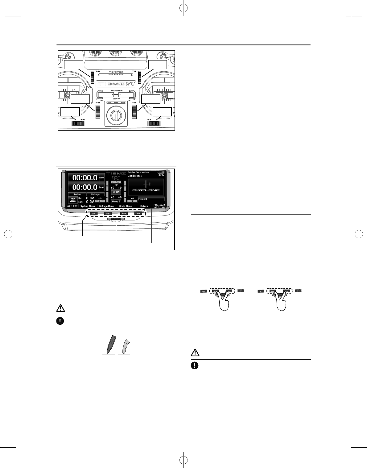
①Timer
If one of two timer displays is pushed, you will
enter the Timer screen of a Linkage menu.
In the button mode of a timer set, it can
also be made a start/stop.
A push on reset will reset a time.
②Menu Button
• System menu • Linkage menu
⑬Menu Button
• Model menu
⑦Home2
A timer and Telemetry data change to
Home2 screen by which it was indicated
by expansion. WARNING
%HVXUHWRFRQ¿UPWKHPRGHOQDPHEHIRUH
À\LQJ\RXUDLUFUDIW
Check the remaining battery as often as
possible and try to charge the battery
regularly. If the battery alarm sounds and
its warning symbol is displayed, land your
aircraft immediately.
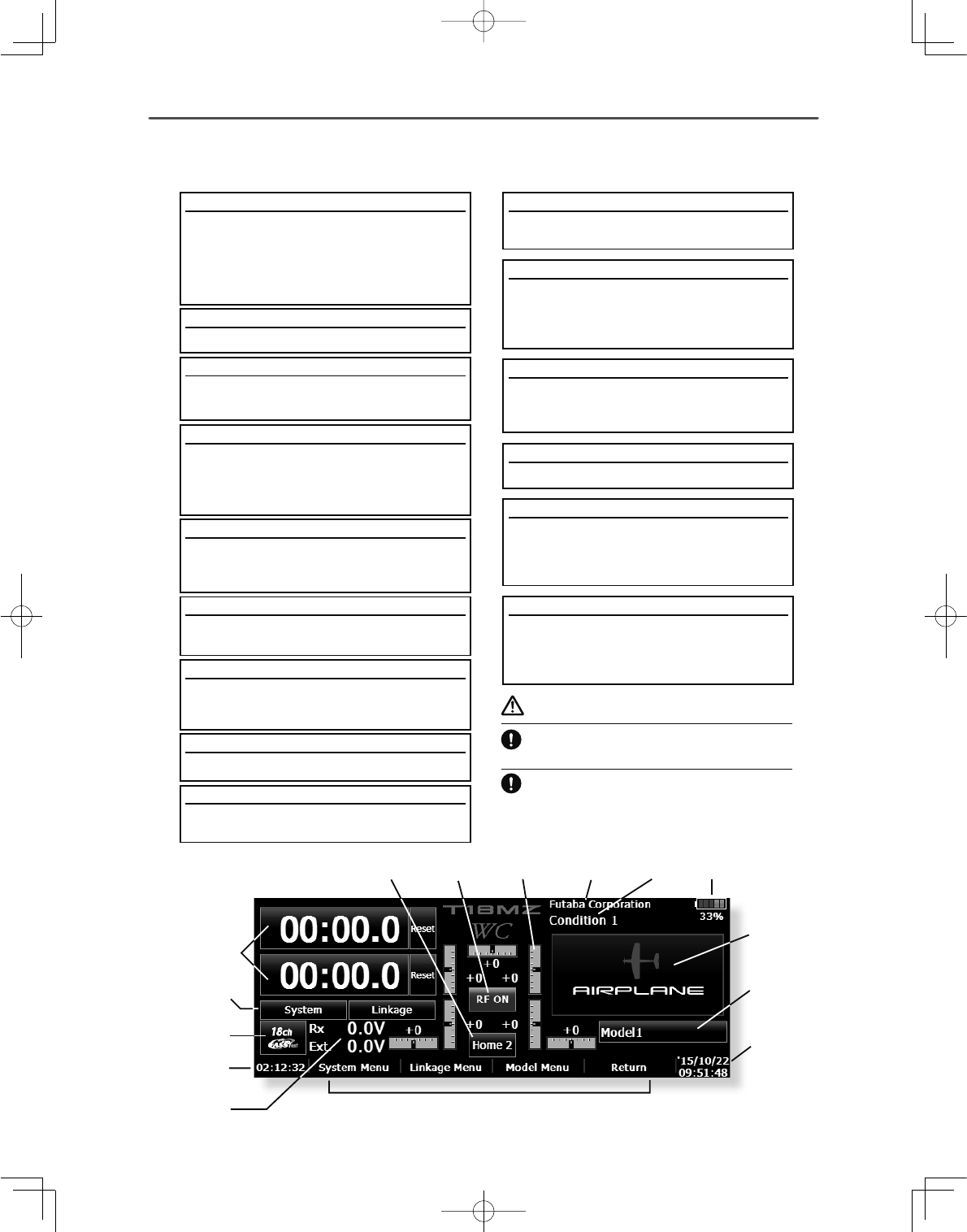
+RPHVFUHHQ
⑪Condition
The condition name that is currently used
is displayed here.
• Push this area to enter the Condition
Select screen.
⑮Clock
This shows the today's date and the
current time.
• Push this area for the Date & Time Setting
screen.
⑩User's name
Push this area to enter the User's Name
Setting screen.
③System Selection
• FASSTest18CH • FASSTest12CH • FASST
MULTI • FASST 7CH • S-FHSS • T-FHSS
④System timer/Reset
• This shows the total accumulated time
used for the transmitter. This can be reset.
(Hour):(Minute):(Second)
Push this area to reset the timer.
⑥Direct buttons
Select and press one of the direct buttons
to enter the menu.
7KLVLVWKH+RPHVFUHHQDQGGHVFULSWLRQVRILWVPHQXV8VH\RXU¿QJHURULQFOXGHGVW\OXVSHQWR
operate the touch screen.
⑫Battery Indicator
•When the remaining battery reaches 30%,
the alarm will beep. Land your aircraft
immediately.
⑧RF Indicator
"ON AIR" or "RF OFF"
⑨Digital trim (T1 to T6, CD)
Push this area to enter the Dial Monitor
screen.
⑭Model Name
The model name that is currently used is
displayed here.
• Push this area to enter the Model Select
screen.
⑤Voltage of Rx/Ext battery
Information from the receiver is displayed
when using a bidirectional system.
FASSTest/T-FHSS Only.
⑬
⑭
⑮
①
②
③
④
⑤⑥
⑦⑧⑨⑩⑪⑫
39
<Basic Operation >
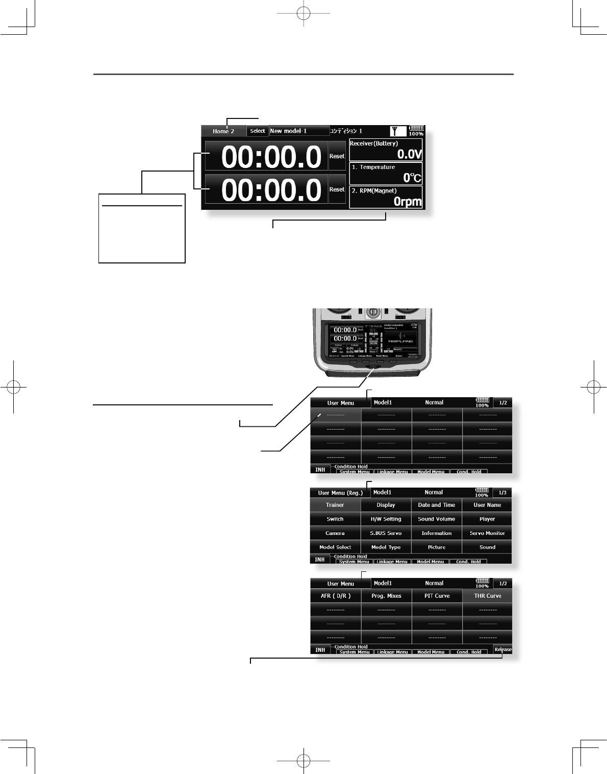
8VHU0HQX
T18MZ-WC has a menu for each of the
following: System, Linkage, and Model. Also,
you can create a personalized User Menu that can
include all of the menus that you use most often.
The User menu can be created by pressing the
Rotary Key.
How to make a User Menu
1. From the home screen, press the Rotary
key for 2 seconds.
7RXFKKHUHWRVHOHFW\RXUÀUVWFKRLFH
3. Once pressed, 4 pages of choices will be
displayed.
4. Make your selection, press your choice
and the first of your "User Menu" will be
entered.
ŏ5HWXUQWRKRPHVFUHHQ
ŏ5HWXUQWRKRPHVFUHHQ
ŏ5HWXUQWRKRPHVFUHHQ
ŏ5HWXUQWR8VHU0HQX
ŏ7RHUDVHDVHOHFWLRQIURP\RXU8VHU0HQXKLJKOLJKWWKHGHVLUHG
menu and press Release. This will remove it from your personal
User Menu, but not from the basic menu. You can always go
back at a later date and re-enter this into your User Menu.
ŏ7KUHHWHOHPHWU\GDWDVFUHHQVFDQEHGLVSOD\HG
If three either is pushed, it will move to a telemetry screen.
Three displays can be changed on a telemetry screen.
*Any change made to data entered from the
User Menu or from the normal method of
use are the same. Changes made in either
way are saved into the transmitter memory.
+RPHVFUHHQ
If [Home2] is pushed, it will become the display to which the timer and the Telemetry data were expanded.
Timer
If one of two timer
displays is pushed,
you will enter the
Timer screen of a
Linkage menu.
40 <Model Basic Setting Procedure >
02'(/%$6,&6(77,1*352&('85(
1. Model addition and call
Initial setting assigns one model to the T18MZ-
WC transmitter. The Model Select function of the
Linkage Menu is used to add models and to select
models which have already been set.
This is convenient when calling a model after its
name has been registered. (Data can also be saved to
the accessory SD card and USB memory)
The currently called model name is displayed
at the top of the screen. Before flying and before
changing any settings, always confirm the model
name.
When a new model is added, the model type
select screen/system type/receiver link automatically
appears. Please be aware that the transmitter will
stop transmitting when you change the model.
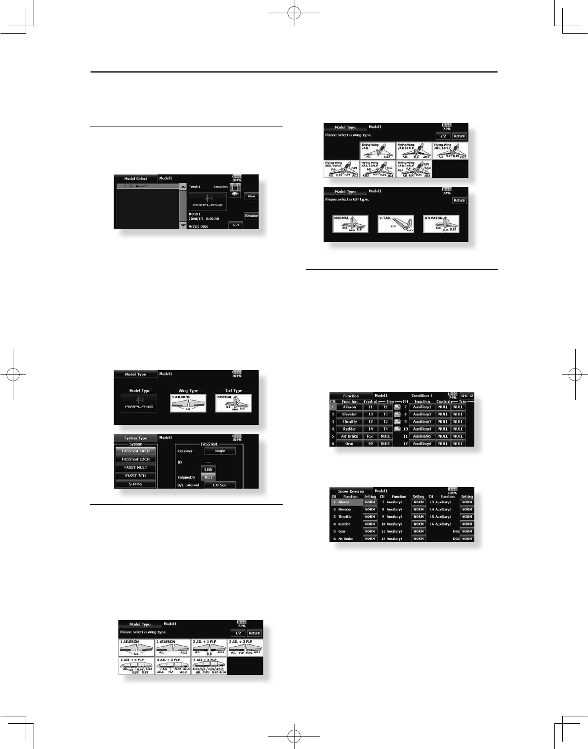
2. Model type selection
Select the model type matched to the fuselage
with the Model Type select function of the Linkage
Menu. For an airplane, select the model type from
among the 3 types: airplane, glider, and motor glider.
When the wing type select screen is displayed and
the wing type is selected when selecting the model
type, the tail type select screen is displayed. Select
the tail type matched to the fuselage.
There are 13 wing types and 3 tail types for
airplane, glider, and motor glider.
$LUSODQHJOLGHUEDVLFVHWWLQJSURFHGXUH
3. Fuselage linkage
Link the ailerons, elevators, throttle, rudder, etc.
in accordance with the model's instruction manual.
For a description of the connection method, see the
receiver and servos connection.
Note: The channel assignment of the T18MZ-WC
is different from that of our existing systems. Note
that even for the same "airplane model", when the
wing type and tail type are different, the channel
assignment has been optimized and may be
different. (The channel assigned to each function
can be checked in the Function menu of the Linkage
Menu.)
ŏ:KHQWKHGLUHFWLRQRIWKHOLQNDJHLVUHYHUVHG
adjust the direction with the Servo Reverse
function in the Linkage Menu.
ŏ&RQQHFWWKHWKURWWOHOLQNDJHVRWKHFDUEXUHWRULV
open at full trim and full open so that the throttle
can be cut.
ŏ$GMXVWWKHQHXWUDOSRVLWLRQDQGUXGGHUDQJOH
with the linkage, and fine tune them with
the Sub Trim and End Point functions (rudder
angle adjustment). To protect the linkage, a
limit position can also be set with the End Point
function. The End Point function can adjust the
amount of up/down and left/right movement,
limit, and servo speed of each channel.
<
<
M
Mo
d
de
l
l
B
Ba
i
si
c
S
Se
tt
tt
i
in
g
P
Pr
oc
d
ed
ure
>
>
41
<Model Basic Setting Procedure >
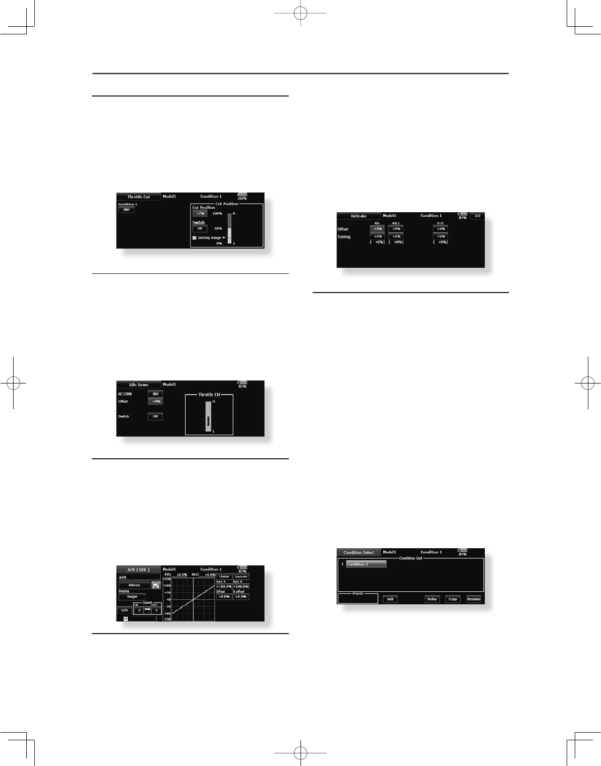
4. Throttle cut setting (In case of engine model)
Throttle cut can be performed with one touch by a
switch without changing the throttle trim position.
Set throttle cut with the Throttle Cut function of
the Linkage Menu. After activating the throttle cut
function and selecting the switch, adjust the throttle
position so that the carburetor becomes full close.
For safety, the throttle cut function operates the
throttle stick in the slow position.
5. Idle down setting (In case of engine model)
The idling speed can be lowered with one touch by
a switch without changing the throttle trim position.
Perform this setting with the Idle Down function of
the Linkage Menu. After activating the Idle Down
function and selecting the switch, adjust the idle
down speed. For safety, the idle down function acts
only when the throttle stick is in the slow position.
*While the Throttle Cut function is in operation, the Idle Down
function does not work.
6. AFR (D/R)
AFR function is used to adjust the throw and
operation curve of the stick, lever, and switch
IXQFWLRQVIRUHDFKÀLJKWFRQGLWLRQ7KLVLVQRUPDOO\
used after End Point (ATV) has defined the
maximum throw directions (End Point acts on ALL
flight condition settings). When mixing is applied
from one channel to another channel, both channels
can be adjusted at the same time by adjusting the
operation rate through the AFR function.
7. Airbrake
This function is used when an air brake is
necessary when taking off or diving, etc.
7KHSUHVHWHOHYDWRUVDQGÀDSVFDPEHUÀDSEUDNH
ÀDSRIIVHWDPRXQWFDQEHDFWLYDWHGE\DVZLWFK
7KHRIIVHWDPRXQWRIWKHDLOHURQHOHYDWRUDQGÀDS
servos can be adjusted as needed. Also the speed of
WKHDLOHURQHOHYDWRUDQGÀDSVHUYRVFDQEHDGMXVWHG
(IN side/OUT side) A delay can be set for each
condition, and a cut switch which will turn OFF the
GHOD\FDQEHFKRVHQ7ULPDPRXQWVFDQEH¿QHWXQHG
by setting a VR. You can also set the auto mode,
which will link Airbrake to a stick, switch, or dial.
A separate stick switch or dial can also be set as the
ON/OFF switch.
$GGLWLRQRIÀLJKWFRQGLWLRQV
The transmitter can install up to eight flight
conditions per model. You can assign all switches
including sticks, switches, trim levers and trim
VZLWFKHVDVÀLJKWFRQGLWLRQVHOHFWLRQVZLWFKHV<RX
can also add delayed mixing to these functions in
order to avoid sudden changes. Moreover, you can
VHWSULRULW\RUGHUIRUÀLJKWFRQGLWLRQVZKHQ\RXVHW
more than one condition. In addition, you can copy
conditions and/or change names of conditions. This
FRPPDQGPD\DOVREHXVHGWRGH¿QHZKDWVZLWFKHV
and/or controls are used to activate each flight
condition.
The Condition Select function automatically
allocates the condition 1 for each model type.
Condition 1 is the default condition, also referred
to as normal, and is the only one active when a new
PRGHOW\SHLVGH¿QHG7KLVFRQGLWLRQLVDOZD\V21
and remains ON until other conditions are activated
by switches.
The Condition Delay can be programmed for each
channel. The Condition Delay is used to change the
servo throw smoothly when switching conditions.
*When a new condition is added, "Condition1" data is
automatically copied.
*Select the condition switch and set the new condition data
with the switch in the ON position. However, if the group
mode (Gr.) was selected in advance, the same data will be
input to all new conditions. Select the single mode (Sngl) and
adjust the condition you want to change.
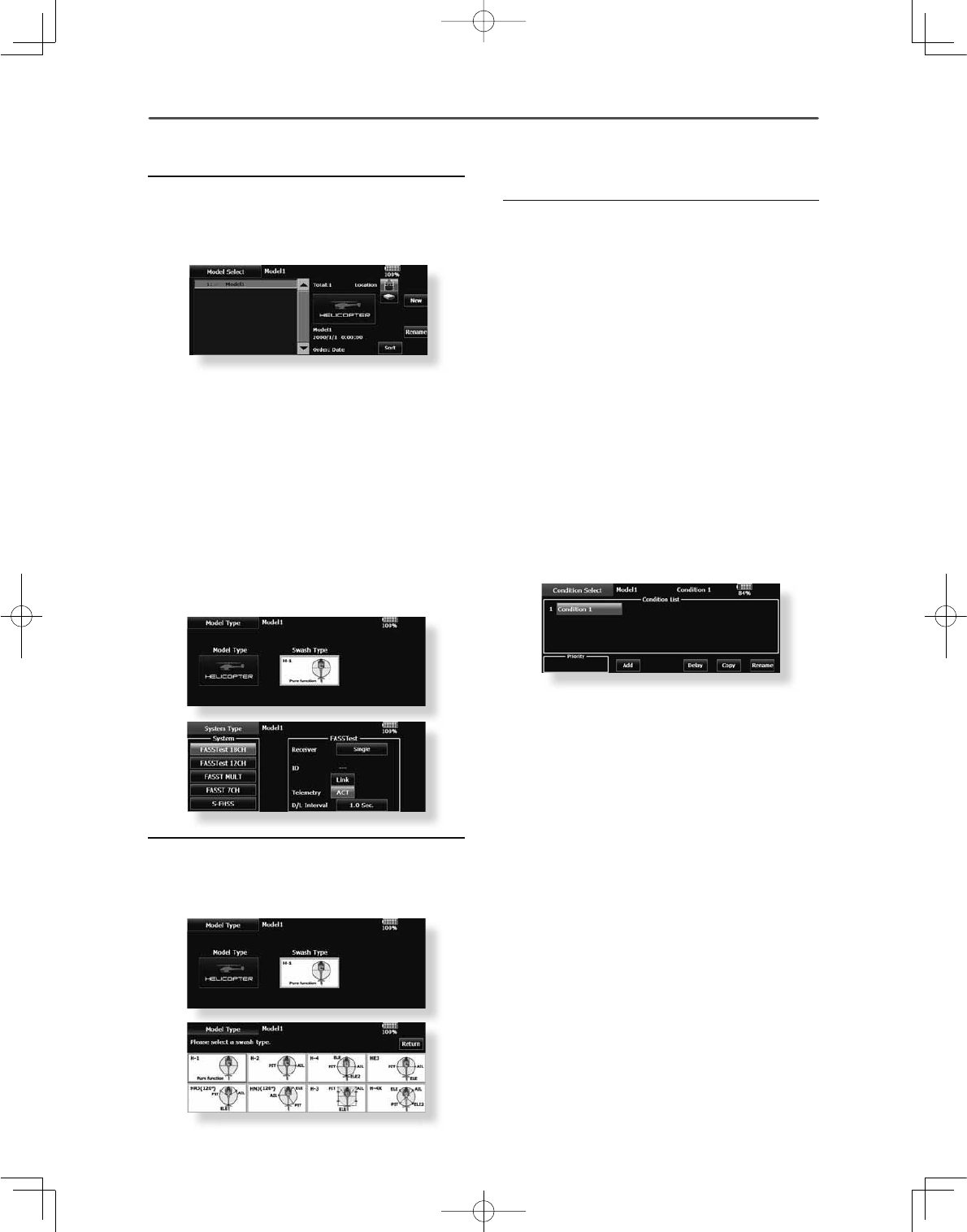
42 <Model Basic Setting Procedure >
1. Model addition and call
Default settings assign one model to the T18MZ-
WC transmitter. To add new models or select
previously setup models, use the Model Select
function in the Linkage Menu.
This is convenient when calling a model after
registering the model names in advance. (Data can
also be saved to the accessory SD card and USB
memory)
The currently called model is displayed at the top
RIWKHVFUHHQ%HIRUHÀ\LQJDQGEHIRUHFKDQJLQJDQ\
VHWWLQJVDOZD\VFRQ¿UPWKHPRGHOQDPH
Please be aware that the transmitter will stop
transmitting when you change the model.
When a new model is added, the model type select
screen/system mode/receiver link automatically
appears. Please be aware that the transmitter will
stop transmitting when you change the model.
2. Model type and swash type selection
When a separate model type is already selected,
select helicopter with the Model Type function of
the Linkage Menu, and then select the swash type
matched to the fuselage.
2
<
<
Mo
Mo
de
de
l
l
Ba
Ba
si
si
c
c
Se
Se
tt
tt
in
in
g
g
Pr
Pr
oc
oc
ed
ed
ur
ur
e
e
>
>
+HOLFRSWHUEDVLFVHWWLQJSURFHGXUH
3. Flight condition addition
The transmitter can install up to eight flight
conditions per model. You can assign all switches
including sticks, switches, trim levers and trim
VZLWFKHVDVÀLJKWFRQGLWLRQVHOHFWLRQVZLWFKHV<RX
can also add delayed mixing to these functions in
order to avoid sudden changes. Moreover, you can
VHWSULRULW\RUGHUIRUÀLJKWFRQGLWLRQVZKHQ\RXVHW
more than one condition. In addition, you can copy
conditions and/or change names of conditions. This
FRPPDQGPD\DOVREHXVHGWRGH¿QHZKDWVZLWFKHV
and/or controls are used to activate each flight
condition.
The Condition Select function automatically
allocates the default Condition 0 (Normal) for each
model type. Condition 0 (Normal) is the only one
active when a new model type is defined. This
condition is always ON, and remains ON until other
conditions are activated by switches.
The Condition Delay can be programmed for each
channel. The Condition Delay is used to change the
servo throw smoothly when switching conditions.
*HQHUDOÀLJKWFRQGLWLRQVHWWLQJH[DPSOH
ŏ1RUPDO8VHLQLWLDOVHWWLQJFRQGLWLRQVRSHUDWH
when switch OFF)
8VHIURPHQJLQHVWDUWLQJWRKRYHULQJ
ŏ,GOHXS6ZLWFKVHWWLQJH[DPSOH2SHUDWHDW
SW-E center)
8VHLQVWDOOWXUQORRSDQGRWKHUPDQHXYHUV
ŏ,GOHXS6ZLWFKVHWWLQJH[DPSOH2SHUDWHDW
SW-E forward side)
8VHLQUROOV
ŏ7KURWWOHKROG6ZLWFKVHWWLQJH[DPSOH2SHUDWH
at SW-G forward side)
8VHLQDXWRURWDWLRQ
The priority is throttle hold/idle up 2/idle up 1/
normal. Throttle hold has the highest priority.
Add other conditions, as required.
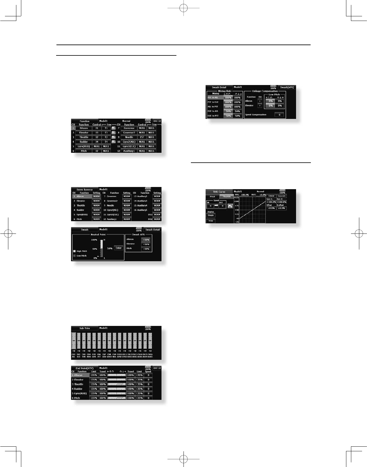
43
<Model Basic Setting Procedure >
Operation of the swash plate near the hovering point
FDQEHFRUUHFWHGE\VZDVK$)5IXQFWLRQFRUUHFWLRQ
PL[LQJ8VHWKLVZKHQSLWFKDLOHURQDQGHOHYDWRU
operation causes the swash plate to deviate from
the normal direction.
&DOOWKH6ZDVKVHWXSĺ6ZDVKGHWDLOVVFUHHQ
Pitch slow side and high side linkage correction is also
SRVVLEOH$GMXVWVRWKDWSLWFKRSHUDWLRQFDXVHVWKH
swash plate to move up and down in the horizontal
state.
5. Throttle curve setting
This function adjusts the pitch operation curve
in relation to the movement of the throttle stick for
each condition.
(17 points curve)
The pitch curve can be freely selected from linear
operation curve to smooth curve, and adjusted to
match the curve you want by means of the T18MZ-
WC’s powerful Curve Edit Function (6 types of
curves can be selected). Up to 17 points can be set
for linear or curve types. However, when using the
3 points or 5 points specified to create a curve, a
simple and smooth curve can be created by selecting
the curve type and reducing the number of input
SRLQWVWRRUDQGWKHQHQWHULQJWKHVSHFL¿HGYDOXH
at the corresponding points that you created.
6HWWLQJH[DPSOH!
Call the throttle curve of each condition with the
condition select switch.
ŏ1RUPDOFXUYHDGMXVWPHQW
Normal curve uses Normal (Linear) type and creates
a basic pitch curve centered near hovering. This
curve is adjusted together with the Throttle Curve
(Normal) so that the engine speed is constant and
up/down control is easiest.
ŏ,GOHXSFXUYHDGMXVWPHQW
The high side pitch curve sets the maximum pitch
regardless of the engine load. The low side pitch
curve creates a curve matched for aerobatics (loop,
roll, 3D, etc.).
Note: When the curve type is changed, the data is
reset.
ŏ7KURWWOHKROGFXUYHDGMXVWPHQW
4. Fuselage linkage
Connect the throttle rudder, ailerons, elevators,
pitch, and other rudder linkages in accordance with
the kit instruction manual. For a description of
the connection method, see "Receiver and servos
connection".
*The channel assignment of the T18MZ-WC is different from
that of our existing systems. (The channel assigned to each
function can be checked at the function menu of the Linkage
Menu.)
ŏ:KHQWKHGLUHFWLRQRIWKHOLQNDJHLVUHYHUVHG
use the Reverse function of the Linkage Menu.
$OVRXVHWKHVZDVK$)5IXQFWLRQLQDQ\VZDVK
set up other than the H-1 mode.
ŏ$GMXVWWKHGLUHFWLRQRIRSHUDWLRQRIWKHJ\UR
(Gyro side function)
ŏ&RQQHFWWKHWKURWWOHOLQNDJHVRLWLVIXOO\FORVHG
with the trim setting all the way down.
ŏ$GMXVWWKHQHXWUDOSRVLWLRQDQGUXGGHUDQJOH
DWWKHOLQNDJHVLGHDQGÀQHWXQHZLWKWKH6XE
Trim function and End Point function (rudder
angle adjustment). To protect the linkage, a
limit position can also be set with the End Point
function.
ŏ6ZDVKSODWHFRUUHFWLRQ([FHSW+PRGH
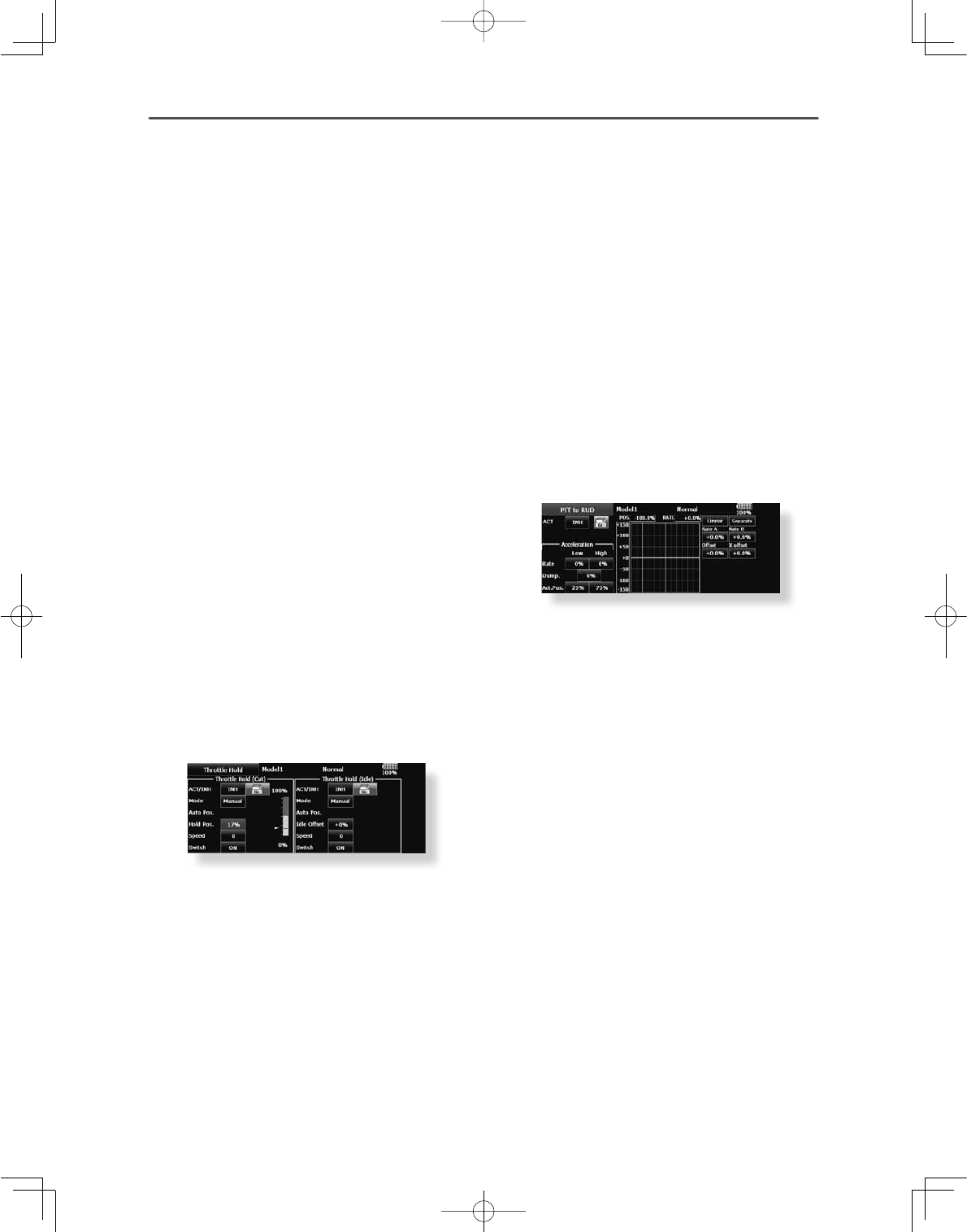
44 <Model Basic Setting Procedure >
&RQÀUPWKDWWKHUDWHRIWKHVORZHVWSRVLWLRQRI
WKHVWLFNLVLQLWLDOVHWWLQJ
%HVXUHWKDWZKHQVHWWRKLJKVLGHWKHFXUYHRI
DQ\FRQGLWLRQGRHVQRWH[FHHG
Example of pitch curve setting:
1. Call the pitch curve of each condition with
the condition select switch.
*Pitch curve graph display can be switched to pitch angle direct
reading display.
$3LWFKFXUYH1RUPDO
Make the pitch at hovering approximately +5º~6º.
Set the pitch at hovering with the stick position at
WKHSRLQWDVWKHVWDQGDUG
*Stability at hovering may be connected to the throttle curve.
Adjustment is easy by using the hovering throttle function and
hovering pitch function together.
%3LWFKFXUYH,GOHXS
The idle up 1 pitch curve function creates a curve
PDWFKHGWRDLUERUQHÁLJKW
Set to -7ºaº as standard.
&3LWFKFXUYH,GOHXS
The high side pitch setting is less than idle up 1.
The standard is +8º.
D. Pitch curve (Hold)
$WDXWRURWDWLRQXVHWKHPD[LPXPSLWFKDWERWK
the high and low sides.
[Pitch angle setting example]
7KURWWOHKROGºaº
6. Throttle hold setting
Call the Throttle Hold function from the Model
Menu and switch to the throttle hold condition with
the condition select switch.
Note: $WLQLWLDOVHWWLQJWKHVHWWLQJPRGHLVWKH
group mode. Since this function is not used at other
conditions, switch to the single mode before setting.
ŏ6HWWLQJWRWKHVWDWHZKLFKDFWLYDWHVWKHIXQFWLRQ
The throttle hold function allows setting for throttle cut
DQGVZLWFKLQJRIWKHIXQFWLRQÀ[HGDWWKHLGOHSRVLWLRQ
by switch for training. Either one or both functions
can be performed.
ŏ+ROGSRVLWLRQVHWWLQJ
This function sets the servo operation position at
throttle hold. (Throttle cut and idle positions)
ŏ2WKHUVHWWLQJV
When you want to link operation with stick
PDQLSXODWLRQWKH$XWRPRGHFDQEHVHW
When you want to adjust the servo speed, adjust
[Speed].
3LWFKWR58'PL[LQJVHWWLQJ
Use this function when you want to suppress
the torque generated by the changes in the pitch
and speed of the main rotor during pitch operation.
Adjust it so that the nose does not swing in the
rudder direction. However, when using a heading
hold gyro like those shown below, do not use Pitch
to RUD mixing.
Note:KHQXVLQJD)XWDED*<VHULHVJ\URRURWKHU
KHDGLQJKROGJ\URWKLV3LWFKWR58'PL[LQJVKRXOG
not be used. The reaction torque is corrected at
WKHJ\URVLGH:KHQRSHUDWLQJWKHJ\URLQWKH$9&6
mode, the mixed signal will cause neutral deviation
symptoms and the gyro will not operate normally.
Call the Pitch to RUD mixing function from the
Model Menu, and set the curve for each condition.
(At initial setting, this function is in the "INH" state.
To use it, set it to the "ON" state.)
(17 points curve)
Curve setting of up to 17 points is possible.
However, in the following setting example, a simple
curve can be adjusted by using the [Linear] curve
type.
Note:$WLQLWLDOVHWWLQJWKHVHWWLQJPRGHLVWKHJURXS
PRGH,QWKLVPRGHWKHVDPHFRQWHQWVDUHVHWDWLQ
all conditions. When you want to set the selected
condition only, switch to the single mode.
6HWWLQJH[DPSOH!
Call the mixing curve of each condition with the
condition select switch.
The throttle hold curve is used when performing auto
rotation dives.
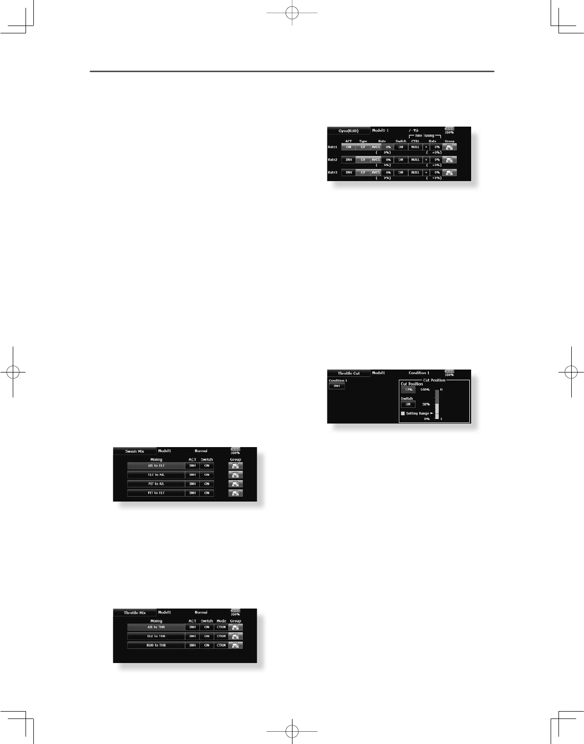
45
<Model Basic Setting Procedure >
$FXUYHVHWWLQJH[DPSOHLVVKRZQEHORZ
$3LWFKWR58'PL[LQJFXUYH1RUPDO
8VHWKHKRYHULQJV\VWHPDQGVHWWKLVFXUYHWR
match take off and landing and vertical climb at a
constant speed.
*For this curve, use the initial setting [Linear] curve
type and adjust the left and right rates in the
[Separate] mode.
%3LWFKWR58'PL[LQJ,GOHXS
8VHWKLVFXUYHLQVWDOOWXUQORRSDQGDGMXVWLWVRWKH
fuselage is facing straight ahead when heading
into the wind.
*For this curve, [Linear] curve type can be used and
the entire curve can be lowered with the [Offset]
button.
&3LWFKWR58'PL[LQJ+ROG
This function is set so that the fuselage is facing
straight ahead during straight line auto rotation. The
SLWFKRIWKHWDLOURWRUEHFRPHVQHDUO\
*For this curve, [Linear] curve type can be used and
the entire curve can be lowered with the [Offset]
button.
ŏ2WKHUVHWWLQJV
The mixing rise characteristic of pitch operation can
EHDGMXVWHG$QDFFHOHUDWLRQ$&/5IXQFWLRQZKLFK
temporarily increases and decreases the
mixing amount, can be set.
6ZDVK0L[FRUUHFWVDLOHURQHOHYDWRUDQGSLWFK
interaction
The swash mix function is used to correct the
swash plate in the aileron (roll) direction and elevator
(cyclic pitch) corresponding to each operation of
each condition.
7KURWWOHPL[LQJVHWWLQJ
RPM loss caused by swash operation of aileron
or elevator can be corrected with the Throttle
Mix function in the Model Menu. The effects of
clockwise and counterclockwise torque applied when
pirouetting can also be corrected.
10. Gyro sensitivity and mode switching
The gyro sensitivity and mode switching function
is dedicated to gyro mixing for each model used, and
can be set for each condition.
ŏ1RUPDOFRQGLWLRQKRYHULQJ*\URVHQVLWLYLW\
maximum
ŏ,GOHXS,GOHXS7KURWWOHKROG*\URVHQVLWLYLW\
minimum
ŏ+RZHYHUDWDXWRURWDWLRQRIDWDLOGULYHQ
helicopter, this function may not have any
affect at high gyro sensitivity.
11. Throttle cut setting
Throttle cut provides an easy way to stop the
HQJLQHE\ÀLSSLQJDVZLWFKZLWKWKHWKURWWOHVWLFNDW
idle. The action is not functional at high throttle to
avoid accidental dead sticks. The switch’s location
and direction must be chosen, as it defaults to
NULL.
*With throttle stick at idle, adjust the cut position
until the engine consistently shuts off, but throttle
linkage is not binding. When finished, touch the
“Throttle Cut” button to exit.
2WKHUVSHFLDOPL[LQJV
ŏ3LWFKWR1HHGOHPL[LQJ
This mixing is used with engines with a construction
ZKLFKDOORZVQHHGOHFRQWUROGXULQJÁLJKWIXHO
DLUPL[WXUHDGMXVWPHQW$QHHGOHFXUYHFDQEH
set. The needle servo rise characteristics at throttle
stick acceleration/deceleration operation can be
DGMXVWHG$FFHOHUDWLRQIXQFWLRQ
ŏ)XHOPL[WXUHIXQFWLRQ
This mixing is used in needle adjustment of engines
which use a fuel mixture control carburetor.
ŏ*RYHUQRUPL[LQJ
This mixing is dedicated governor mixing when a
JRYHUQRULVXVHG8SWRUDWHVVSHHGVFDQEH
switched for each condition.
46 <Model Basic Setting Procedure >
6HUYRVFRQQHFWLRQE\PRGHOW\SH
The T18MZ-WC transmitter channels are automatically assigned for optimal combination according to the
type selected with the Model Type function of the Linkage Menu. The channel assignment (initial setting) for
each model type is shown below. Connect the receiver and servos to match the type used.
*The set channels can be checked at the Function screen of the Linkage Menu. The channel assignments can also be changed. For more
information, read the description of the Function menu.
Airplane/glider/motor glider
Ɣ$LUSODQHDQG9WDLO
RX
CH
1AIL 2AIL 2AIL+1FLAP 2AIL+2FLAP
Airplane Glider Airplane Glider Airplane Glider Airplane Glider
EP EP EP EP
1 Aileron Aileron Aileron Aileron Aileron Aileron Aileron Aileron Aileron Aileron Aileron Aileron
2 Elevator Elevator Elevator Elevator Elevator Elevator Elevator Elevator Elevator Elevator Elevator Elevator
3 Throttle Motor AUX7 Throttle Motor AUX7 Throttle Motor AUX7 Throttle Motor AUX7
4 Rudder Rudder Rudder Rudder Rudder Rudder Rudder Rudder Rudder Rudder Rudder Rudder
5 Gear AUX6 AUX6 Gear AUX6 AUX6 Gear AUX6 AUX6 Aileron2 Aileron2 Aileron2
6 Airbrake Airbrake Airbrake Aileron2 Aileron2 Aileron2 Aileron2 Aileron2 Aileron2 Flap Flap Flap
7 AUX5 AUX5 AUX5 AUX5 AUX5 AUX5 Flap Flap Flap Flap2 Flap2 Flap2
8 AUX4 AUX4 AUX4 AUX4 AUX4 AUX4 AUX5 AUX5 AUX5 Gear AUX6 AUX6
9 AUX3 AUX3 AUX3 AUX3 AUX3 AUX3 AUX4 AUX4 AUX4 AUX5 AUX5 AUX5
10 AUX2 AUX2 AUX2 AUX2 AUX2 AUX2 AUX3 AUX3 AUX3 AUX4 AUX4 AUX4
11 AUX1 AUX1 AUX1 AUX1 AUX1 AUX1 AUX2 AUX2 AUX2 AUX3 AUX3 AUX3
12 AUX1 AUX1 AUX1 AUX1 AUX1 AUX1 AUX1 AUX1 AUX1 AUX2 AUX2 AUX2
13 AUX1 AUX1 AUX1 AUX1 AUX1 AUX1 AUX1 AUX1 AUX1 AUX1 AUX1 AUX1
14 AUX1 AUX1 AUX1 AUX1 AUX1 AUX1 AUX1 AUX1 AUX1 AUX1 AUX1 AUX1
15 AUX1 AUX1 AUX1 AUX1 %XWWHUÀ\ %XWWHUÀ\ AUX1 %XWWHUÀ\ %XWWHUÀ\ AUX1 %XWWHUÀ\ %XWWHUÀ\
16 AUX1 AUX1 AUX1 Camber Camber Camber Camber Camber Camber Camber Camber Camber
DG1SWSWSWSWSWSWSWSWSWSWSWSW
DG2SWSWSWSWSWSWSWSWSWSWSWSW
RX
CH
2AIL+4FLAP 4AIL+2FLAP 4AIL+4FLAP
Airplane Glider Airplane Glider Airplane Glider
EP EP EP
1 Aileron Aileron Aileron Aileron Aileron Aileron Aileron Aileron Aileron
2 Elevator Elevator Elevator Elevator Elevator Elevator Elevator Elevator Elevator
3 Throttle Rudder Rudder Throttle Rudder Rudder Throttle Rudder Rudder
4 Rudder Aileron2 Aileron2 Rudder Aileron2 Aileron2 Rudder Aileron2 Aileron2
5 Gear Flap Flap Gear Aileron3 Aileron3 Gear Aileron3 Aileron3
6 Aileron2 Flap2 Flap2 Aileron2 Aileron4 Aileron4 Aileron2 Aileron4 Aileron4
7 Flap Flap3 Flap3 Aileron3 Flap Flap Aileron3 Flap Flap
8 Flap2 Flap4 Flap4 Aileron4 Flap2 Flap2 Aileron4 Flap2 Flap2
9 Flap3 Motor AUX7 Flap Motor AUX7 Flap Flap3 Flap3
10 Flap4 AUX6 AUX6 Flap2 AUX6 AUX6 Flap2 Flap4 Flap4
11 AUX5 AUX5 AUX5 AUX5 AUX5 AUX5 Flap3 Motor AUX7
12 AUX4 AUX4 AUX4 AUX4 AUX4 AUX4 Flap4 AUX6 AUX6
13 AUX3 AUX3 AUX3 AUX3 AUX3 AUX3 AUX5 AUX5 AUX5
14 AUX2 AUX2 AUX2 AUX2 AUX2 AUX2 AUX4 AUX4 AUX4
15 AUX1 %XWWHUÀ\ %XWWHUÀ\ AUX1 %XWWHUÀ\ %XWWHUÀ\ AUX3 %XWWHUÀ\ %XWWHUÀ\
16 Camber Camber Camber Camber Camber Camber Camber Camber Camber
DG1SWSWSWSWSWSWSWSWSW
DG2SWSWSWSWSWSWSWSWSW
FASST 7CH
S-FHSS
FASSTest 12CH
FASSTest 18CH FASST MULT T-FHSS
The output
CH of each
system
FASST 7CH
S-FHSS
FASSTest 12CH
FASSTest 18CH FASST MULT T-FHSS
The output
CH of each
system
47
<Model Basic Setting Procedure >
RX
CH
1AIL 2AIL 2AIL+1FLAP 2AIL+2FLAP
Airplane Glider Airplane Glider Airplane Glider Airplane Glider
EP EP EP EP
1 Aileron Aileron Aileron Aileron Aileron Aileron Aileron Aileron Aileron Aileron Aileron Aileron
2 Elevator Elevator Elevator Elevator Elevator Elevator Elevator Elevator Elevator Elevator Elevator Elevator
3 Throttle Motor AUX7 Throttle Motor AUX7 Throttle Motor AUX7 Throttle Motor AUX7
4 Rudder Rudder Rudder Rudder Rudder Rudder Rudder Rudder Rudder Rudder Rudder Rudder
5 Gear AUX6 AUX6 Gear AUX6 AUX6 Elevator2 Elevator2 Elevator2 Elevator2 Elevator2 Elevator2
6 Airbrake Airbrake Airbrake Aileron2 Aileron2 Aileron2 Aileron2 Aileron2 Aileron2 Aileron2 Aileron2 Aileron2
7Elevator2 Elevator2 Elevator2 Elevator2 Elevator2 Elevator2 Flap Flap Flap Flap Flap Flap
8 AUX5 AUX5 AUX5 AUX5 AUX5 AUX5 Gear AUX6 AUX6 Flap2 Flap2 Flap2
9 AUX4 AUX4 AUX4 AUX4 AUX4 AUX4 AUX5 AUX5 AUX5 Gear AUX6 AUX6
10 AUX3 AUX3 AUX3 AUX3 AUX3 AUX3 AUX4 AUX4 AUX4 AUX5 AUX5 AUX5
11 AUX2 AUX2 AUX2 AUX2 AUX2 AUX2 AUX3 AUX3 AUX3 AUX4 AUX4 AUX4
12 AUX1 AUX1 AUX1 AUX1 AUX1 AUX1 AUX2 AUX2 AUX2 AUX3 AUX3 AUX3
13 AUX1 AUX1 AUX1 AUX1 AUX1 AUX1 AUX1 AUX1 AUX1 AUX2 AUX2 AUX2
14 AUX1 AUX1 AUX1 AUX1 AUX1 AUX1 AUX1 AUX1 AUX1 AUX1 AUX1 AUX1
15 AUX1 AUX1 AUX1 AUX1 %XWWHUÀ\ %XWWHUÀ\ AUX1 %XWWHUÀ\ %XWWHUÀ\ AUX1 %XWWHUÀ\ %XWWHUÀ\
16 AUX1 AUX1 AUX1 Camber Camber Camber Camber Camber Camber Camber Camber Camber
DG1SWSWSWSWSWSWSWSWSWSWSWSW
DG2SWSWSWSWSWSWSWSWSWSWSWSW
RX
CH
2AIL+4FLAP 4AIL+2FLAP 4AIL+4FLAP
Airplane Glider Airplane Glider Airplane Glider
EP EP EP
1 Aileron Aileron Aileron Aileron Aileron Aileron Aileron Aileron Aileron
2 Elevator Elevator Elevator Elevator Elevator Elevator Elevator Elevator Elevator
3 Throttle Motor AUX7 Throttle Motor AUX7 Throttle Motor AUX7
4 Rudder Rudder Rudder Rudder Rudder Rudder Rudder Rudder Rudder
5Elevator2 Elevator2 Elevator2 Elevator2 Elevator2 Elevator2 Elevator2 Elevator2 Elevator2
6 Aileron2 Aileron2 Aileron2 Aileron2 Aileron2 Aileron2 Aileron2 Aileron2 Aileron2
7 Flap Flap Flap Aileron3 Aileron3 Aileron3 Aileron3 Aileron3 Aileron3
8 Flap2 Flap2 Flap2 Aileron4 Aileron4 Aileron4 Aileron4 Aileron4 Aileron4
9 Flap3 Flap3 Flap3 Flap Flap Flap Flap Flap Flap
10 Flap4 Flap4 Flap4 Flap2 Flap2 Flap2 Flap2 Flap2 Flap2
11 Gear AUX6 AUX6 Gear AUX6 AUX6 Flap3 Flap3 Flap3
12 AUX5 AUX5 AUX5 AUX5 AUX5 AUX5 Flap4 Flap4 Flap4
13 AUX4 AUX4 AUX4 AUX4 AUX4 AUX4 Gear AUX6 AUX6
14 AUX3 AUX3 AUX3 AUX3 AUX3 AUX3 AUX5 AUX5 AUX5
15 AUX2 %XWWHUÀ\ %XWWHUÀ\ AUX2 %XWWHUÀ\ %XWWHUÀ\ AUX4 %XWWHUÀ\ %XWWHUÀ\
16 Camber Camber Camber Camber Camber Camber Camber Camber Camber
DG1SWSWSWSWSWSWSWSWSW
DG2SWSWSWSWSWSWSWSWSW
Ɣ$LOHYDWRU
FASST 7CH
S-FHSS
FASSTest 12CH
FASSTest 18CH FASST MULT T-FHSS
The output
CH of each
system
FASST 7CH
S-FHSS
FASSTest 12CH
FASSTest 18CH FASST MULT T-FHSS
The output
CH of each
system
48 <Model Basic Setting Procedure >
Ɣ7DLOOHVVZLQJ
RX
CH
2AIL 2AIL+1FLAP 2AIL+2FLAP
Airplane Glider Airplane Glider Airplane Glider
EP EP EP
1 Aileron Aileron Aileron Aileron Aileron Aileron Aileron Aileron Aileron
2 AUX4 AUX4 AUX4 AUX4 AUX4 AUX4 AUX4 AUX4 AUX4
3 Throttle Motor AUX7 Throttle Motor AUX7 Throttle Motor AUX7
4 Rudder Rudder Rudder Rudder Rudder Rudder Rudder Rudder Rudder
5 Gear AUX6 AUX6 Gear AUX6 AUX6 Aileron2 Aileron2 Aileron2
6 Aileron2 Aileron2 Aileron2 Aileron2 Aileron2 Aileron2 Flap Flap Flap
7 AUX5 AUX5 AUX5 Flap Flap Flap Flap2 Flap2 Flap2
8 AUX3 AUX3 AUX3 AUX5 AUX5 AUX5 Gear AUX6 AUX6
9 AUX2 AUX2 AUX2 AUX3 AUX3 AUX3 AUX5 AUX5 AUX5
10 AUX1 AUX1 AUX1 AUX2 AUX2 AUX2 AUX3 AUX3 AUX3
11 AUX1 AUX1 AUX1 AUX1 AUX1 AUX1 AUX2 AUX2 AUX2
12 AUX1 AUX1 AUX1 AUX1 AUX1 AUX1 AUX1 AUX1 AUX1
13 AUX1 AUX1 AUX1 AUX1 AUX1 AUX1 AUX1 AUX1 AUX1
14 AUX1 AUX1 AUX1 AUX1 %XWWHUÀ\ %XWWHUÀ\ AUX1 %XWWHUÀ\ %XWWHUÀ\
15 Camber Camber Camber Camber Camber Camber Camber Camber Camber
16 Elevator Elevator Elevator Elevator Elevator Elevator Elevator Elevator Elevator
DG1SWSWSWSWSWSWSWSWSW
DG2SWSWSWSWSWSWSWSWSW
RX
CH
2AIL+4FLAP 4AIL+2FLAP 4AIL+4FLAP
Airplane Glider Airplane Glider Airplane Glider
EP EP EP
1 Aileron Aileron Aileron Aileron Aileron Aileron Aileron Aileron Aileron
2 Aileron2 Aileron2 Aileron2 Aileron2 Aileron2 Aileron2 Aileron2 Aileron2 Aileron2
3 Throttle Motor AUX7 Throttle Motor AUX7 Throttle Motor AUX7
4 Rudder Rudder Rudder Rudder Rudder Rudder Rudder Rudder Rudder
5 Flap Flap Flap Aileron3 Aileron3 Aileron3 Aileron3 Aileron3 Aileron3
6 Flap2 Flap2 Flap2 Aileron4 Aileron4 Aileron4 Aileron4 Aileron4 Aileron4
7 Flap3 Flap3 Flap3 Flap Flap Flap Flap Flap Flap
8 Flap4 Flap4 Flap4 Flap2 Flap2 Flap2 Flap2 Flap2 Flap2
9 AUX4 AUX4 AUX4 AUX4 AUX4 AUX4 Flap3 Flap3 Flap3
10 Gear AUX6 AUX6 Gear AUX6 AUX6 Flap4 Flap4 Flap4
11 AUX5 AUX5 AUX5 AUX5 AUX5 AUX5 AUX4 AUX4 AUX4
12 AUX3 AUX3 AUX3 AUX3 AUX3 AUX3 Gear AUX6 AUX6
13 AUX2 AUX2 AUX2 AUX2 AUX2 AUX2 AUX5 AUX5 AUX5
14 AUX1 %XWWHUÀ\ %XWWHUÀ\ AUX1 %XWWHUÀ\ %XWWHUÀ\ AUX3 %XWWHUÀ\ %XWWHUÀ\
15 Camber Camber Camber Camber Camber Camber Camber Camber Camber
16 Elevator Elevator Elevator Elevator Elevator Elevator Elevator Elevator Elevator
DG1SWSWSWSWSWSWSWSWSW
DG2SWSWSWSWSWSWSWSWSW
FASST 7CH
S-FHSS
FASSTest 12CH
FASSTest 18CH FASST MULT T-FHSS
The output
CH of each
system FASST 7CH
S-FHSS
FASSTest 12CH
FASSTest 18CH FASST MULT T-FHSS
The output
CH of each
system

49
<Model Basic Setting Procedure >
Ɣ7DLOOHVVZLQJ:LQJOHW5XGGHU
RX
CH
2AIL 2AIL+1FLAP 2AIL+2FLAP
Airplane Glider Airplane Glider Airplane Glider
EP EP EP
1 Aileron Aileron Aileron Aileron Aileron Aileron Aileron Aileron Aileron
2 RUD2 RUD2 RUD2 RUD2 RUD2 RUD2 RUD2 RUD2 RUD2
3 Throttle Motor AUX7 Throttle Motor AUX7 Throttle Motor AUX7
4 Rudder Rudder Rudder Rudder Rudder Rudder Rudder Rudder Rudder
5 Gear AUX6 AUX6 Gear AUX6 AUX6 Aileron2 Aileron2 Aileron2
6 Aileron2 Aileron2 Aileron2 Aileron2 Aileron2 Aileron2 Flap Flap Flap
7 AUX5 AUX5 AUX5 Flap Flap Flap Flap2 Flap2 Flap2
8 AUX3 AUX3 AUX3 AUX5 AUX5 AUX5 Gear AUX6 AUX6
9 AUX2 AUX2 AUX2 AUX3 AUX3 AUX3 AUX5 AUX5 AUX5
10 AUX1 AUX1 AUX1 AUX2 AUX2 AUX2 AUX3 AUX3 AUX3
11 AUX1 AUX1 AUX1 AUX1 AUX1 AUX1 AUX2 AUX2 AUX2
12 AUX1 AUX1 AUX1 AUX1 AUX1 AUX1 AUX1 AUX1 AUX1
13 AUX1 AUX1 AUX1 AUX1 AUX1 AUX1 AUX1 AUX1 AUX1
14 AUX1 AUX1 AUX1 AUX1 %XWWHUÀ\ %XWWHUÀ\ AUX1 %XWWHUÀ\ %XWWHUÀ\
15 Camber Camber Camber Camber Camber Camber Camber Camber Camber
16 Elevator Elevator Elevator Elevator Elevator Elevator Elevator Elevator Elevator
DG1SWSWSWSWSWSWSWSWSW
DG2SWSWSWSWSWSWSWSWSW
RX
CH
2AIL+4FLAP 4AIL+2FLAP 4AIL+4FLAP
Airplane Glider Airplane Glider Airplane Glider
EP EP EP
1 Aileron Aileron Aileron Aileron Aileron Aileron Aileron Aileron Aileron
2 Aileron2 Aileron2 Aileron2 Aileron2 Aileron2 Aileron2 Aileron2 Aileron2 Aileron2
3 Throttle Motor AUX7 Throttle Motor AUX7 Throttle Motor AUX7
4 Rudder Rudder Rudder Rudder Rudder Rudder Rudder Rudder Rudder
5 Flap Flap Flap Aileron3 Aileron3 Aileron3 Aileron3 Aileron3 Aileron3
6 Flap2 Flap2 Flap2 Aileron4 Aileron4 Aileron4 Aileron4 Aileron4 Aileron4
7 Flap3 Flap3 Flap3 Flap Flap Flap Flap Flap Flap
8 Flap4 Flap4 Flap4 Flap2 Flap2 Flap2 Flap2 Flap2 Flap2
9 RUD2 RUD2 RUD2 RUD2 RUD2 RUD2 Flap3 Flap3 Flap3
10 Gear AUX6 AUX6 Gear AUX6 AUX6 Flap4 Flap4 Flap4
11 AUX5 AUX5 AUX5 AUX5 AUX5 AUX5 RUD2 RUD2 RUD2
12 AUX3 AUX3 AUX3 AUX3 AUX3 AUX3 Gear AUX6 AUX6
13 AUX2 AUX2 AUX2 AUX2 AUX2 AUX2 AUX5 AUX5 AUX5
14 AUX1 %XWWHUÀ\ %XWWHUÀ\ AUX1 %XWWHUÀ\ %XWWHUÀ\ AUX3 %XWWHUÀ\ %XWWHUÀ\
15 Camber Camber Camber Camber Camber Camber Camber Camber Camber
16 Elevator Elevator Elevator Elevator Elevator Elevator Elevator Elevator Elevator
DG1SWSWSWSWSWSWSWSWSW
DG2SWSWSWSWSWSWSWSWSW
FASST 7CH
S-FHSS
FASSTest 12CH
FASSTest 18CH FASST MULT T-FHSS
The output
CH of each
system FASST 7CH
S-FHSS
FASSTest 12CH
FASSTest 18CH FASST MULT T-FHSS
The output
CH of each
system
* Output channels differ by each system of a table. When using a system with few channels, there
is a wing type which cannot be used. It cannot be used when there is a function required out of
WKHUDQJHRIWKHDUURZRID¿JXUH
50 <Model Basic Setting Procedure >
CH
H-4/H-4X Swash
All Other
1Aileron Aileron
2Elevator Elevator
3
Throttle Throttle
4
Rudder Rudder
5Gyro Gyro
6
Pitch Pitch
7Governor
Governor
8Elevator2
Governor2
9GYRO2 GYRO2
10 GYRO3 GYRO3
11
Governor2 Needle
12
Needle AUX5
13
AUX4
14
AUX3
15
AUX2
16
AUX1
DG1
SW
DG2
CH
H-4/H-4X Swash
All Other
1Aileron Aileron
2Elevator Elevator
3
Throttle Throttle
4
Elevator2 Rudder
5Pitch Pitch
6
Gyro Gyro
7Governor
Governor
8Rudder
Governor2
9GYRO2 GYRO2
10 GYRO3 GYRO3
DG1
SW
DG2
Helicopter
Ɣ)$667HVW&+)$66708/7,)$667&+6)+667)+66
Ɣ)$667HVW&+
FASST 7CH
S-FHSS
FASSTest 18CH FASST MULT T-FHSS
The output
CH of each
system
D
G1
SW
D
G1
SW
X4
FASSTest 12CH
The output
CH of each
system

51
<System Menu >
+(/,&237(5
$,53/$1(*/,'(5
6<67(00(18
6\VWHP0HQXIXQFWLRQVWDEOH
ƔTrainer : Starts and sets the trainer system.
ƔDisplay : Display adjustment and auto power off setting.
ƔDate & Time : Sets the date and time (system clock setting) and resets the timer.
ƔUser Name : User name registration and ID Pin number.
ƔSwitch : Toggle switch type setting (Set when the switch is replaced.)
ƔH/W Setting : Hardware reverse / Stick setting / Calibration.
ƔSund Volume : Adjust the volume of: Key Operation / Error Warning / Trim & Center Click / Timer Event
ƔPlayer :5HSURGXFWLRQRIPXVLF¿OH
ƔCamera : Built in 0.3 megapixel camera.
ƔS.BUS Servo : S.BUS servo setting.
ƔInformation : Displays the program version, SD card information, and product ID.
ƔUnit System : 7KHXQLWRIDGLVSOD\LVFKDQJHG0HWULFļ<DUG3RXQG
ƔRange Check : The output of the transmitter is lowered, for Range checking.
The System Menu sets up functions of the
transmitter, this does not set up any model data.
ŏ:KHQWKH6\VWHP0HQXEXWWRQLVWRXFKHG
WKHPHQXVKRZQEHORZLVFDOOHGXS7RXFK
WKHIXQFWLRQEXWWRQWKDW\RXZDQWWRHQWHU
ŏ5HWXUQWR+RPHVFUHHQ
52 <System Menu >
+(/,&237(5
$,53/$1( */,'(5
7UDLQHU 7UDLQHUV\VWHPVHWXSDQGXVH
70=:&WUDLQHUV\VWHPPDNHVLWSRVVLEOH
for the instructor to chose which channels and
operation modes that can be used in the student's
transmitter. The function and rate of each channel
can be set, the training method can also be matched
to the student's skill level. Two transmitters must
be connected by an optional Trainer Cord, and the
Instructors’ transmitter should be programmed for
trainer operation, as described below.
When the Instructor activates the trainer switch, the
student has control of the aircraft (if MIX/ FUNC/
NORM mode is turned on, the Instructor can make
corrections while the student has control). When
the switch is released the Instructor regains control.
This is very useful if the student gets the aircraft
into an undesirable situation.
ŏ6HWWLQJGDWDDUHVWRUHGWRPRGHOGDWD
ŏ6WXGHQWUDWHFDQEHDGMXVWHGDW0,;)81&
1250PRGH
ŏ$FWLYDWHGVWXGHQWFKDQQHOVFDQEHVHOHFWHG
E\VZLWFKHV
Notes: This trainer system can be used in the
following manner;
1. In the T18MZ(WC) (including FX-40, T12Z
and T12FG) transmitter and a conventional
transmitter, if the channel order is different.
It is necessary to match the channel order
in the Linkage Menu when connecting it
with other than a T18MZ(WC). Or use "Trainer
student channel setting function"
2. Be sure that all channels work correctly in
ERWKWUDQVPLWWHUVEHIRUHÁ\LQJ
Corresponding types of transmitters and trainer mode settings:
7\SHVRIWUDQVPLWWHUV ,QVWUXFWRUVWUDQVPLWWHUVHWWLQJV 6WXGHQWVWUDQVPLWWHUVHWWLQJV
)UHTVHWWLQJ 7UDLQHUVHWWLQJ )UHTVHWWLQJ 7UDLQHUVHWWLQJ 7UDLQHU&RUGV
,QVWUXFWRU 6WXGHQW 0RGPRGH &+PRGH 0RGPRGH &+PRGH 0RGPRGH
70=:&76=
76*);
70=:&76=76*
); $UELWUDU\ &+ $UELWUDU\ &+
)*&7UDLQHU
&RUGV
70=:&
70=);7=
7)*
);
$UELWUDU\ &+ 3&0*
* &+ 330
70=:& 7)*); $UELWUDU\ &+ )$6670/7
&+ )$66708/7
70=:& 7&7&7&7(;
7(; $UELWUDU\ &+ 330 )*7UDLQHU&RUGV
70=:& 7&*7&* $UELWUDU\ &+ $UELWUDU\ )*7UDLQHU&RUGV
70=:& 7-7-7-7. $UELWUDU\ &+ $UELWUDU\
)*&7UDLQHU
&RUGV
70=);7=
7)*); 70=:& $UELWUDU\ &+ $UELWUDU\ &+
7)*); 70=:& $UELWUDU\ &+ $UELWUDU\ &+
7&7&*7-7&
7&
7&*7-7.
70=:& $UELWUDU\ $UELWUDU\ &+
ŏ7RXFKWKH>7UDLQHU@EXWWRQLQWKH6\VWHP0HQXWR
FDOOWKHVHWXSVFUHHQ7KHVHWXSVFUHHQIRUWKH
7HDFKHU6WXGHQWPRGHLVVKRZQEHORZ
Student mode
6HW7HDFKHU6WXGHQWEXWWRQWR6WXGHQW
&KDQJH$&7,1+EXWWRQIURP,1+WR2))
RU21
6HWWKH&+PRGHWR&+&+RU&+VHH
WKHDERYHFKDUWIRUWKHWUDLQHUPRGHVHWWLQJV
ŏ5HWXUQWR6\VWHP0HQX
Note: In "student mode", only the teacher side
can turn on and off the power of the student's
transmitter. Keep the power switch always at
off position.
53
<System Menu >
+(/,&237(5
$,53/$1(*/,'(5
Teacher mode
6HW7HDFKHU6WXGHQWEXWWRQWR7HDFKHU
&KDQJH$&7,1+EXWWRQIURP,1+WR2))
RU21
6HWWKH&+PRGHWR&+&+RU&+
VHHWKHDERYHPHQWLRQHGFKDUWIRUWKHWUDLQHU
PRGHVHWWLQJV
&DOOXSWKH6ZLWFK6HWWLQJVFUHHQE\WRXFKLQJ
6ZLWFK7KHQVHWWKHGHVLUHGVZLWFKDQGRQ
RIIGLUHFWLRQ
6HOHFWWKHVZLWFKPRGH,I\RXVHOHFW1250
WKHWUDLQHUIXQFWLRQZLOOEHWXUQHGRQRURII
E\DVZLWFKSRVLWLRQ,I\RXVHOHFW$/721
DQG2))RIWKHWUDLQHUIXQFWLRQVZLWFKHV
DOWHUQDWLYHO\HYHU\WLPHWKHVZLWFKLVWXUQHG
RQ7KLVPHDQVWKHVWXGHQWVLGHFDQEH
RSHUDWHGZLWKRXWKROGLQJWKHVZLWFKOHYHU
7KH,QVWUXFWRUVLGHVHOHFWVWKHFKDQQHOIRU
FRQWURO7KUHHRSHUDWLQJPRGHVDUHDYDLODEOH
"NORM" mode (Normal mode);
7KHVWXGHQWZLOOKDYHQRQHRIWKHVHWWLQJVIURP
WKH7HDFKHUVUDGLR
"MIX" mode;
6WXGHQWKDVIXOODGYDQWDJHRIDOOPL[HVDQGVHWWLQJV
LQ7HDFKHUVUDGLR3OXVWKH7HDFKHUKDVWKHDELOLW\WR
RYHUULGHWKHVWXGHQWZKLOHWKHVZLWFKLVDFWLYDWHG
"FUNC" mode (Function mode);
6WXGHQWKDVFRQWURORIDOOPL[HVDQGUDWH
VHWWLQJVRI7HDFKHUVUDGLR
6HWWKHVZLWFKHVDQGUDWHVRIHDFKFKDQQHO
6ZLWFKWRWKHGHWDLOVVHWXSVFUHHQE\WRXFKLQJ
WKHSDJHVZLWFKLQJEXWWRQ>@DWWKHWRS
ULJKWKDQGFRUQHURIWKHVFUHHQ6WXGHQW
RSHUDWLRQIRUHDFKFKDQQHOFDQEHVHWKHUH
>6ZLWFK@7KHVZLWFKHVWKDWFDQEHRSHUDWHG
E\WKHVWXGHQWFDQEHVHW6:$a6:+66
DQG66FDQEHVHOHFWHG
>5DWH@6HUYRWUDYHOYHUVXVVWXGHQWRSHUDWLRQ
FDQEHVHW7KLVFDQRQO\EHXVHGLQWKH
)81&/0,;1250PRGHV
Note: In "teacher mode", the trainer function
won’t show that is is activated unless the
Instructors' transmitter receives signals from
the student's transmitter via the trainer cord.
Be sure to confirm this after connecting your
trainer cable.
ŏ5HWXUQWR6\VWHP0HQX
ŏ6WXGHQWUDWH
ŏ7KHVHWXSVFUHHQIRUWKHLQVWUXFWRUPRGHLV
VKRZQEHORZ
54 <System Menu >
+(/,&237(5
$,53/$1( */,'(5
Student channel setting
2SHQWKH6\VWHP0HQXWUDLQHUVFUHHQ
6HOHFW>7HDFKHU@
:KHQ>)81&@>0,;@>1250@LVVHOHFWHGDVWKH
PRGHRIWKHFKDQQHOWREHVHWWKH>6WXGHQW
&+@VHWWLQJEXWWRQLVGLVSOD\HG:KHQ
>2))@>6WXGHQW&+@VHWWLQJLVQRWSHUIRUPHG
:KHQWKH>6WXGHQW&+@EXWWRQLVSUHVVHGWKH
&KDQQHO6HOHFWVFUHHQLVGLVSOD\HG6HOHFWWKH
FKDQQHO
&+PRGH&+
&+PRGH&+
&+PRGH&+
Trainer student channel setting function
7KHFKDQQHOIXQFWLRQFDQEHVHOHFWHGDQGUHDUUDQJHG
for the student transmitter (when using either
"FUNC" "MIX" "NORM") in the Trainer function
of the transmitter. This makes trainer connection
easy even when the instructor and student channel
assignment are different.
Student side Student CH
CH1 Aileron
CH2 Elevator
CH3 Throttle
CH4 Rudder
CH5 Gear
CH6 Flap
CH7 Aileron2
CH8 Aux5
CH9 Aux4
CH10 Aux3
CH11 Aux2
CH12 Aux1
Instructor side
CH2Elevator CH4Rudder CH3Throttle CH1Aileron --Aileron2 CH6Flap CH5Gear CH8Aux5 CH9Aux4 CH10Aux3 CH11Aux2 CH12Aux1
([DPSOHRIVWXGHQW&+VHWWLQJ!
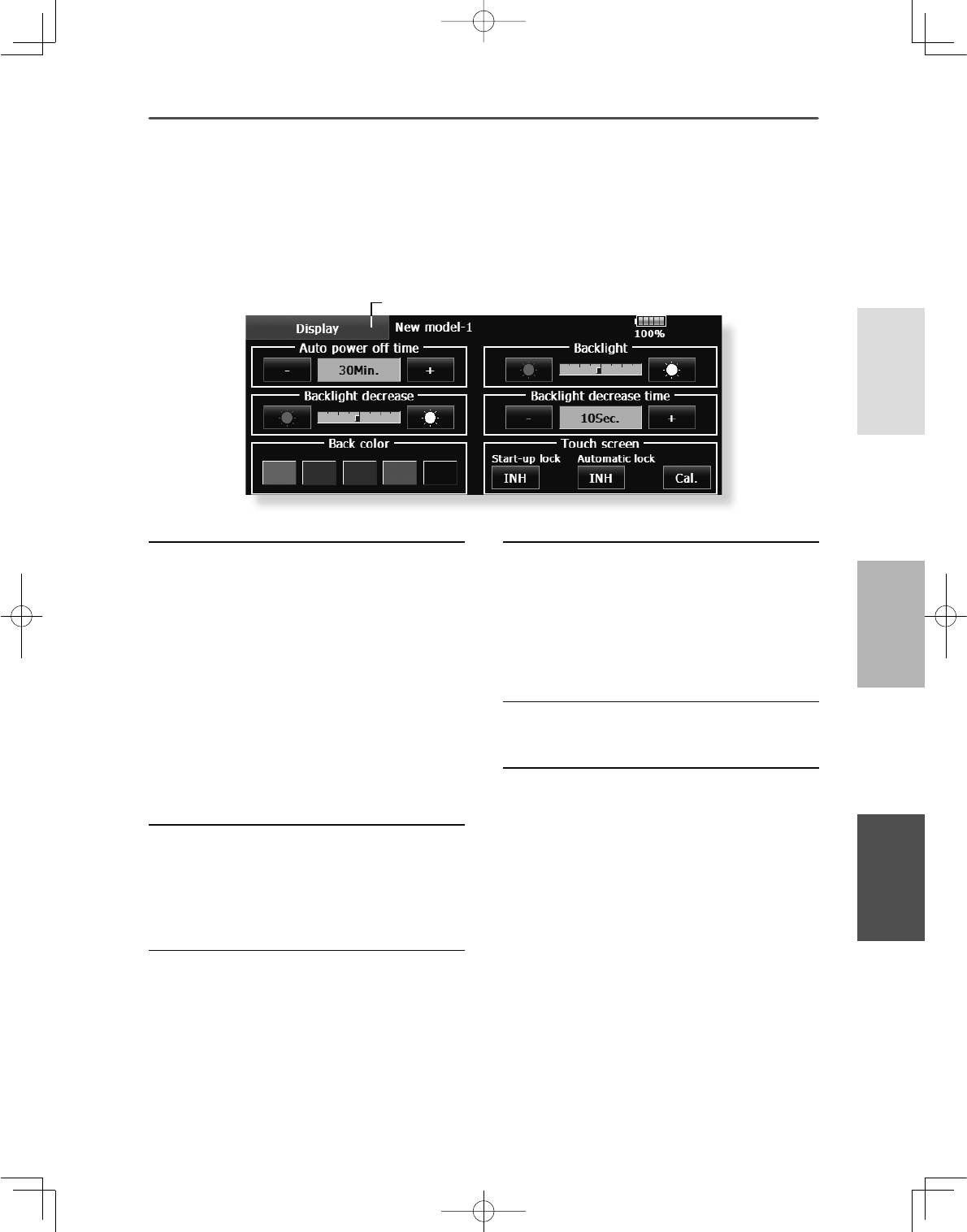
55
<System Menu >
+(/,&237(5
$,53/$1(*/,'(5
Auto power off time setting
7KHIXQFWLRQWRSUHYHQWDEDWWHU\IURP
GLVFKDUJLQJE\IDLOXUHRIWKHSRZHUVXSSO\RID
WUDQVPLWWHUWRHUDVH
$GMXVWWKHDXWRSRZHURIIWLPHZLWKWKHOHIW
DQGULJKWVLGHEXWWRQV
:KHQWKHWLPHWKHWUDQVPLWWHULVLQDFWLYHUHDFKHV
WKHVHWWLPHWKHSRZHULVWXUQHGRIIDXWRPDWLFDOO\
7KLVWLPHFDQEHVHWXSWRKRXULQPLQXWHV
LQFUHPHQWV7KHDXWRSRZHU RIIIXQFWLRQFDQDOVR
EHGHDFWLYDWHG
$QDXGLEOHDODUPLVVRXQGHGDQGDQDODUPVFUHHQ
LVGLVSOD\HGIURP PLQXWHVEHIRUHDXWRSRZHU
RIIDQGWKHWLPH UHPDLQLQJXQWLODXWRSRZHURIILV
GLVSOD\HG:KHQDVWLFNRUVZLWFKLVRSHUDWHGZKLOH
WKHDODUPVFUHHQLVEHLQJGLVSOD\HGWKHDODUPLV
FOHDUHGDQGWKHGLVSOD\LVUHWXUQHGWRWKHKRPH
VFUHHQ
Backlighting brightness adjustment
$GMXVWWKHEDFNOLJKWLQJEULJKWQHVVZLWKWKHOHIW
DQGULJKWVLGHEXWWRQV
:KHQWKHULJKWVLGHEXWWRQLVWRXFKHGWKH
EDFNOLJKWLQJEHFRPHVEULJKWHU:KHQ WKHOHIW
VLGHEXWWRQLVWRXFKHG WKHEDFNOLJKWLQJEHFRPHV
GDUNHU
Backlight decrease brightness adjustment
$GMXVWWKHEDFNOLJKWGHFUHDVHEULJKWQHVVZLWK
WKHOHIWDQGULJKWVLGHEXWWRQV
:KHQWKHULJKWVLGHEXWWRQLVWRXFKHGWKH
EDFNOLJKWLQJEHFRPHVEULJKWHU:KHQ WKHOHIW
VLGHEXWWRQLVWRXFKHG WKHEDFNOLJKWLQJEHFRPHV
GDUNHU
,WFDQQRWEHPDGHEULJKWHUWKDQ%DFNOLJKWLQJ
EULJKWQHVVDGMXVWPHQW
'LVSOD\ /&'VFUHHQDGMXVWPHQWDQGDXWRSRZHURIIVHWWLQJ
The following LCD screen adjustments and auto power off setting are possible:
ŏ$XWRSRZHURIIWLPHVHWWLQJ
ŏ%DFNOLJKWLQJEULJKWQHVVDGMXVWPHQW
ŏ%DFNJURXQGFRORUFKDQJH
ŏ7RXFKSDQHOVFUHHQFDOLEUDWLRQDQGWRXFKSDQHOORFNFRUUHFWLRQ
ŏ7RXFKWKH>'LVSOD\@EXWWRQLQWKH6\VWHP0HQXWR
FDOOWKHVHWXSVFUHHQVKRZQEHORZ
ŏ5HWXUQWR6\VWHP0HQX
Backlight decrease time
<RXFDQVHWD WLPHSHULRGWRGHFUHDVHWKH/&'
EDFNOLJKW7KLVIXQFWLRQFRXQWV WKHSHULRGWKDWWKH
WRXFKSDQHOKDVQRW EHHQRSHUDWHG7KLVWLPHFDQ
EHVHWE\WHQVHFRQGVWHSV<RXFDQDOVRWXUQRIIWKH
EDFNOLJKWGHFUHDVHLI\RXOLNH
7KHEDFNOLJKWFRQVXPHVD ODUJHDPRXQWRISRZHU
:HUHFRPPHQG\RXWR WXUQRIIWKHEDFNOLJKWE\
VHWWLQJWKHEDFNOLJKWSRZHURII WLPHWRDERXWRQH
PLQXWH
Background color
7RXFKWKHEXWWRQRIWKHFRORU\RXZDQWWRFKDQJH
7KHUHDUHÀYHEDFNJURXQGFRORUV
Touch screen
[Start-up lock],1+ ⇒21LWLVWRXFKSDQHOORFNHG
ZKHQHYHULWWXUQVRQWKHSRZHUVXSSO\RI70=:&
,WZLOOEHFDQFHOHGLI6DQG6NH\DUHSXVKHGVLPXOW
DQHRXVO\
[Automatic lock],1+ ⇒21,WV\QFKURQL]HVZLWK
%DFNOLJKWGHFUHDVHWLPHDQG EHFRPHVDSDQHO
ORFN,WZLOOEHFDQFHOHGLI6DQG6NH\DUHSXVKHG
VLPXOWDQHRXVO\
[Cal.]calibration7KLVIXQFWLRQDGMXVWVWKHORFDWLRQ
RIWRXFKSDQHO7RXFK &DOLEUDWLRQEXWWRQDQGWKHQ
SUHVV<HVWKHFDOLEUDWLRQVFUHHQZLOOSRSXS7RXFK
WKHFHQWHURIWKHFURVVKDLUFXUVRURQWKHVFUHHQZLWK
WKHVW\OXVSHQ$V VRRQDVWKHV\VWHPUHFRJQL]HV WKH
SRVLWLRQWKHFXUVRUZLOOPRYHRQWRWKHQH[WSRVLWLRQ
5HSHDWWKLVSURFHGXUHDV ORQJDVWKHFXUVRUPRYHV
WRQH[WSRVLWLRQ<RXZLOOGRWKLVÀYHWLPHV&DOLEUDWLRQ
ZLOOEHFDUULHGRXW EDVHGRQWKHILYHSRVLWLRQV
'LVDSSHDUDQFHRIWKHFURVV KDLUFXUVRUPHDQVWKH
FDOLEUDWLRQKDVEHHQFRPSOHWHG7RXFKDQ\SRLQWRQ
WKHVFUHHQWRUHWXUQWRWKHSUHYLRXVVFUHHQ
,QRUGLQDU\RSHUDWLRQWKLV FDOLEUDWLRQLVQRW
QHFHVVDU\,I\RXQRWLFH WKHWRXFKSDQHOLV
QRWIXQFWLRQLQJFRUUHFWO\DIWHUORQJXVHZH
UHFRPPHQG\RXFDUU\RXWWKLVFDOLEUDWLRQ
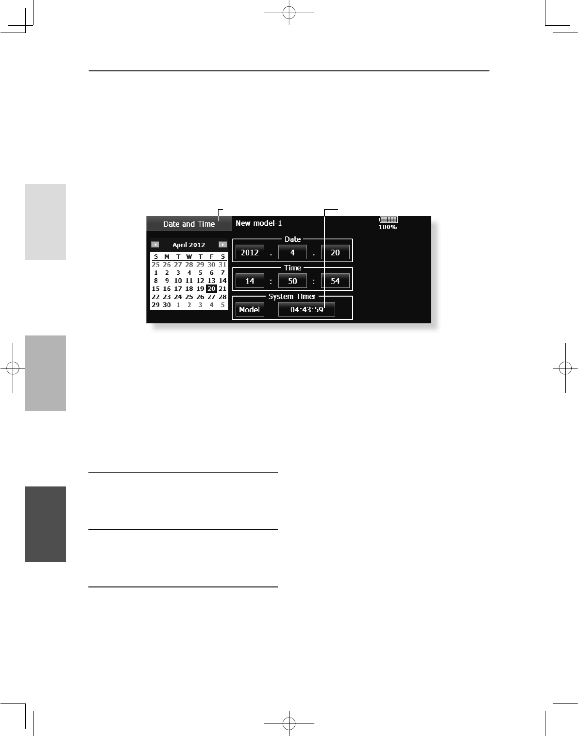
56 <System Menu >
+(/,&237(5
$,53/$1( */,'(5
Date setting
7RXFKWKH<HDU0RQWKRU'D\EXWWRQDQG
VHWWKHGDWHE\WRXFKLQJWKH>@RU>@EXWWRQ
7KHGDWHFDQDOVR EHVHWE\SUHVVLQJWKHGDWHRQ
WKHFDOHQGDUVKRZQDWWKHOHIW
Time setting
7RXFKWKH+RXURU0LQXWHEXWWRQDQGVHW
WKHWLPHE\WRXFKLQJWKH>@RU>@EXWWRQ
:KHQWKH6HFRQGEXWWRQLVWRXFKHGWKH
WLPHULVVHWWRVHFRQGV
Integrating timer reset
7KHLQWHJUDWLQJWLPHUVKRZVWKHWRWDOWLPH
WKDWKDVHODSVHGVLQFHWKHODVWUHVHW
:KHQWKH>6\VWHP7LPHU@EXWWRQLVWRXFKHG
WKHWLPHULVUHVHW
'DWHDQG7LPH 'DWHDQGWLPHVHWWLQJV\VWHPFORFNVHWWLQJDQGLQWHJUDWLQJWLPHU
UHVHWWLQJ
This function adjusts the system clock of the
70=:&WUDQVPLWWHU3HUIRUPWKLVVHWWLQJ
when you purchase the set and when adjustment is
necessary.
The integrating timer can also be reset.
*The integrating timer is displayed on the Home screen.
ŏ7RXFKWKH>'DWHDQG7LPH@EXWWRQLQWKH6\VWHP
0HQXWRFDOOWKHVHWXSVFUHHQVKRZQEHORZ
ŏ5HWXUQWR6\VWHP0HQX ŏ,ILWSXVKHVDWLPHUZLOOUHVHW
ŏ7RWDO5HJDUGOHVVRIDPRGHODGGLWLRQDOWLPHLQFDVHD
SRZHUVXSSO\21LVGLVSOD\HG
0RGHO7KHDGGLWLRQDOWLPHZKHQWKHSRZHUVXSSO\ZDVVHW
WR21LVGLVSOD\HGIRUHYHU\PRGHO
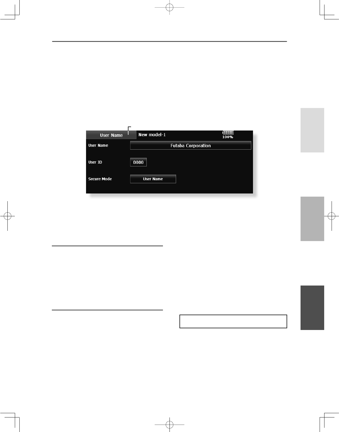
57
<System Menu >
+(/,&237(5
$,53/$1(*/,'(5
8VHU1DPH 8VHUQDPHUHJLVWUDWLRQDQG3,1VHWWLQJ
7KLVIXQFWLRQUHJLVWHUVWKH70=:&XVHUQDPH
A PIN can also be set to protect the set data or user
name.
*Set the PIN carefully. When a system PIN is set, if you forget
the PIN, none of the settings can be changed. In this case, the
system must be reset by the Futaba Service Center.
ŏ7RXFKWKH>8VHU1DPH@EXWWRQLQWKH6\VWHP0HQX
WRFDOOWKHVHWXSVFUHHQVKRZQEHORZ
ŏ5HWXUQWR6\VWHP0HQX
User name registration
:KHQWKH8VHU1DPHER[LVWRXFKHGD
NH\ERDUGDSSHDUVRQWKHVFUHHQ
(QWHUWKHXVHUQDPHIURPWKLVNH\ERDUG
$XVHUQDPHRIXSWRFKDUDFWHUVFDQEH
HQWHUHG
7KHVHWXVHUQDPHLVGLVSOD\HGRQWKH+RPHVFUHHQ
)RUDGHWDLOHGGHVFULSWLRQRIWKHLQSXWPHWKRGVHH
>8VHU1DPH5HJLVWUDWLRQ&KDUDFWHU,QSXW 0HWKRG@
LQWKH%DVLF2SHUDWLRQVHFWLRQ
User name or set data protection
7RXFKWKH6HFXULW\0RGHEXWWRQDQGVHOHFW
WKHPRGH7KHPRGHLVVZLWFKHGHDFKWLPH
WKHEXWWRQLVWRXFKHG
8VHU1DPH6HOHFWZKHQ \RXZDQWWRSURWHFWWKH
XVHUQDPHRQO\
6\VWHP6HOHFWZKHQ\RXZDQWWRSURWHFWDOOWKHVHW
GDWD
:KHQWKHXVHU,'EXWWRQLVWRXFKHGD3,1
LQSXWVFUHHQDSSHDUV,QSXWD3,1RIXSWR
GLJLWV
:KHQWKH5HWXUQNH\LVWRXFKHGWKHGLVSOD\
UHWXUQVWRWKHSUHFHGLQJVFUHHQ
:KHQWKHWUDQVPLWWHUSRZHULVWXUQHGRIIWKH
VHWVHFXULW\PRGHEHFRPHVDFWLYH
:KHQD3,1LV VHWIRUWKHXVHUQDPH LWPXVWEH
HQWHUHGWKHHDFKWLPHWKH8VHU1DPHVFUHHQLV
RSHQHG
:KHQD6\VWHP3,1LVVHWDEXWWRQGLVSOD\LQJDNH\
LFRQDSSHDUVRQWKH+RPHVFUHHQ
:KHQ\RXZDQWWRFKDQJH DQ\VHWWLQJVWRXFKWKLV
EXWWRQDQGHQWHUWKH3,1
,I\RXZDQWWRQXOOLI\\RXUFXUUHQWSDVVZRUG
VHWWKHSDVVZRUGWRGHIDXOWYDOXH
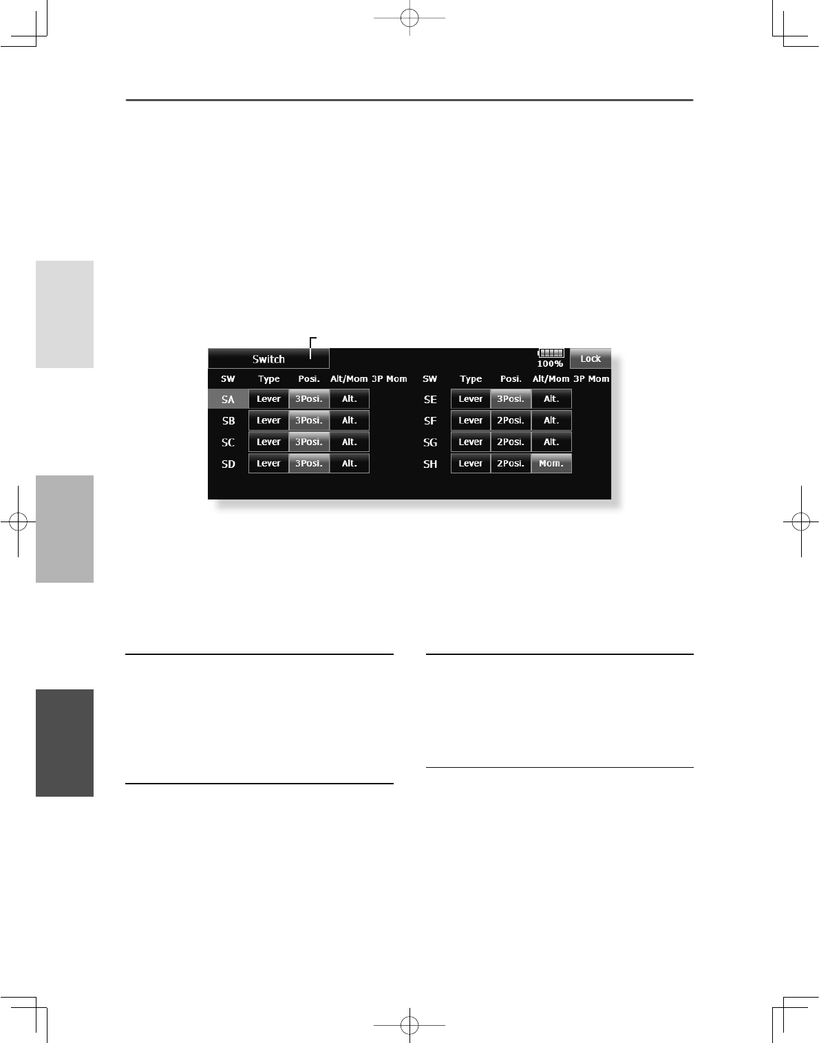
58 <System Menu >
+(/,&237(5
$,53/$1( */,'(5
Switch selection
6HOHFWWKHVZLWFKW\SHE\WRXFKLQJWKH>7\SH@
EXWWRQFRUUHVSRQGLQJWRWKHVZLWFKWREH
UHSODFHG
>/HYHU@7RJJOHVZLWFK
>%XWWRQ@3XVKEXWWRQ
>'LDO@.QRE
ŏ6HWWLQJIRUWRJJOHVZLWFKLVVKRZQDERYH
2/3 position selection
7RXFKWKH3RVLEXWWRQFRUUHVSRQGLQJWRWKH
VZLWFKDQGVHOHFWWKHSRVLWLRQW\SH
>3RVL@SRVLWLRQ
>3RVL@SRVLWLRQ
7RJJOHVZLWFKW\SHVHWWLQJ6HWWLQJZKHQWKHVZLWFKZDVUHSODFHG
If you modify the location of the switches on the
right and left (top) of the transmitter, you should be
VXUHWRUHDVVLJQIXQFWLRQVWRWKHVZLWFKHVIRUSURSHU
operation.
A “Lock” is included to prevent settings from being
modified by mistake. When you need to change
settings, unlock this by pressing “Lock”. It will
then read “Unlock” and you can make changes as
required.
ŏ7RXFKWKH>6ZLWFK@ EXWWRQLQWKH6\VWHP0HQXWR
FDOOXSWKHVHWXSVFUHHQVKRZQEHORZ
ŏ5HWXUQWR6\VWHP0HQX
[Alt/Mom] mode selection
6HOHFWWKHRSHUDWLRQPRGHE\WRXFKLQJWKH
>$OW0RP@EXWWRQFRUUHVSRQGLQJWRWKHVZLWFK
>$OW@$OWHUQDWHW\SH
>0RP@6HOIUHWXUQW\SH
ŏ6HOHFWLRQRIWKH>0RP@PRGHZLWKDSRVLWLRQ
W\SHVZLWFKLVVKRZQDERYH
"3P Mom" mode selection
6HOHFWWKHRSHUDWLRQPRGHE\WRXFKLQJWKH
30RPEXWWRQFRUUHVSRQGLQJWRWKHVZLWFK
>6LQJOH@2QHVLGHVHOIUHWXUQW\SH
>'XDO@%RWKGLUHFWLRQVVHOIUHWXUQW\SH
6ZLWFK
59
<System Menu >
+(/,&237(5
$,53/$1(*/,'(5
Operation direction reversal method
7RXFKWKHVHWWLQJEXWWRQFRUUHVSRQGLQJWRWKH
+:+DUGZDUH\RXZDQWWRUHYHUVH
5HYHUVHWKH+:E\WRXFKLQJ><HV@:KHQ\RX
ZDQWWRVWRSRSHUDWLRQWRXFK>1R@
>1RUPDO@1RUPDORSHUDWLRQGLUHFWLRQ
>5HYHUVH@5HYHUVHVWKHRSHUDWLRQGLUHFWLRQ
+:6HWWLQJ 6WLFNVZLWFKWULPOHYHUDQGNQRERSHUDWLRQGLUHFWLRQUHYHUVDO+DUGZDUH
UHYHUVH6WLFNUHVSRQVHDQGK\VWHULVLVDGMXVWPHQW6WLFN6HWWLQJ&DOLEUDWLRQ
This function is for adjusting the sticks, switches,
and trim characteristics. It is not unless necessary.
H/W Reverse
This function reverses the operation signal of the
sticks, switches, trimmer levers, and knobs.
Note: This setting reverses the actual operation
signal, but does not change the display of
the indicators on the display. Use the Normal
mode as long as there is no special reason to
use the Reverse mode.
ŏ7RXFKWKH>+:6HWWLQJ@EXWWRQDWWKH6\VWHP
0HQXWRFDOOWKHVHWXSVFUHHQVKRZQEHORZ
ŏ5HWXUQWR6\VWHP0HQX
Stick Setting
This function sets the servo response and hysteresis
for stick operation for each condition. The control
feeling of the stick can be adjusted to match the
aerobatics.
Calibration
Usually, this calibration is unnecessary.
Please perform this calibration, only if a change at
the center of a stick should arise after prolonged use.
ŏ7RXFKWKH>+:5HYHUVH@EXWWRQDWWKH+:
6HWWLQJ0HQXWRFDOOWKHVHWXSVFUHHQVKRZQ
EHORZ
ŏ5HWXUQWR+:6HWWLQJ0HQX
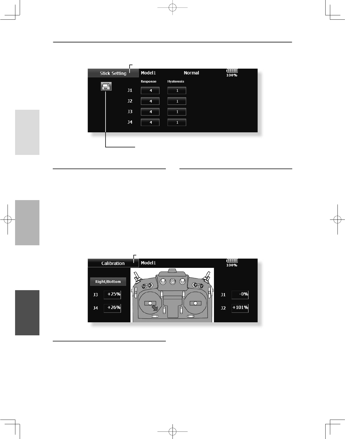
60 <System Menu >
+(/,&237(5
$,53/$1( */,'(5
Response adjustment
7RXFKWKHVHWWLQJEXWWRQFRUUHVSRQGLQJWRWKH
VWLFNZLWKWKHUHVSRQVH\RXZDQWWRDGMXVW
$GMXVWPHQWEXWWRQVDSSHDURQWKHULJKWKDQG
VLGHRIWKHVWLFNVHWXSVFUHHQ
8VHWKHDGMXVWPHQWEXWWRQVWRDGMXVWWKH
UHVSRQVH
,QLWLDOYDOXH
$GMXVWPHQWUDQJHa:KHQWKHDGMXVWPHQW
YDOXHLVODUJHWKHUHVSRQVHEHFRPHVVORZ
How to Calibrate
&KRRVHWKHVWLFNWRFDOLEUDWHULJKWDQGOHIW
7KHVWLFNLVVHWDWQHXWUDODQGWKH>QHXWUDO@
EXWWRQLVSXVKHG
7KHVWLFNLVKHOGDWIXOOULJKWDQGIXOOERWWRP
GLDJRQDOWKH>5LJKW%RWWRP@EXWWRQLV
SXVKHG
7KHVWLFNLVKHOGDWIXOOOHIWDQGIXOOWRS
GLDJRQDOWKH>/HIW7RS@EXWWRQLVSXVKHG
ŏ7RXFKWKH>6WLFN6HWWLQJ@EXWWRQDWWKH+:6HWWLQJ
0HQXWRFDOOWKHVHWXSVFUHHQVKRZQEHORZ
ŏ7RXFKWKH>&DOLEUDWLRQ@EXWWRQDWWKH+:6HWWLQJ
0HQXWRFDOOWKHVHWXSVFUHHQVKRZQEHORZ
ŏ5HWXUQWR+:6HWWLQJ0HQX
ŏ*URXS6LQJOHPRGHVZLWFKLQJ*U6QJO
)RUPRUHLQIRUPDWLRQVHHWKHGHVFULSWLRQDWWKHEDFNRIWKLVPDQXDO
Hysteresis adjustment
7RXFKWKHVHWWLQJEXWWRQFRUUHVSRQGLQJWR
WKHVWLFNZKRVHK\VWHUHVLV\RXZDQWWRDGMXVW
$GMXVWPHQWEXWWRQVDSSHDURQWKHULJKWKDQG
VLGHRIWKHVWLFNVHWXSVFUHHQ
8VHWKHDGMXVWPHQWEXWWRQVWRDGMXVWWKH
K\VWHUHVLV
,QLWLDOYDOXH
$GMXVWPHQWUDQJHa:KHQWKHDGMXVWPHQW
YDOXHLVODUJHWKHK\VWHUHVLVYDOXHEHFRPHV
ODUJH
ŏ5HWXUQWR+:6HWWLQJ0HQX
3OHDVHGRQRWSUHVVWKHVWLFNWRRÀUPO\LQDQ\
GLUHFWLRQZKHQGRLQJWKHFDOLEUDWLRQ
&KHFNDIWHUFDOLEUDWLRQWRPDNHVXUHWKDWQHXWUDO
LVDQGERWWRPULJKWVLGHZLOOEHDQGWKH
WRSOHIWVLGHLVEHFRPH

61
<System Menu >
+(/,&237(5
$,53/$1(*/,'(5
6RXQG9ROXPH 6RXQG9ROXPHVHWWLQJ
This function can set the volume of "Key Operation",
"Error/Warning", "Trim & Center Click" and "Timer
Event" respectively.
*If you have set the PIN try not to forget it. When a system
PIN is set, if you forget the PIN, none of the settings can be
changed or entered. In this case, the system must be reset by
the Futaba Service Center.
ŏ7RXFKWKH>6RXQG9ROXPH@EXWWRQLQWKH6\VWHP
0HQXWRFDOOWKHVHWXSVFUHHQVKRZQEHORZ
ŏ5HWXUQWR6\VWHP0HQX
Sound Volume Setting method
:KHQWKH6RXQG9ROXPHER[LVWRXFKHGWKH
DERYHVFUHHQZLOODSSHDU
<RXFDQFKDQJHWKHVRXQGYROXPHE\
WRXFKLQJWKHEXWWRQRIIRXULWHPV
,I\RXWRXFK WKHYROXPHZLOOLQFUHDVH,I\RX
WRXFKWKHWKHYROXPHZLOOGHFUHDVH
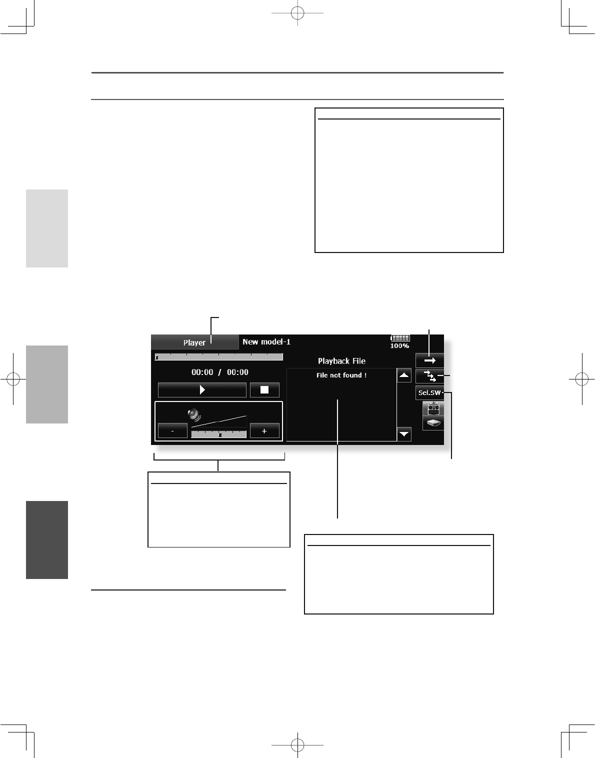
62 <System Menu >
+(/,&237(5
$,53/$1( */,'(5
Copy / Delete / Rename
'DWDLVFKRVHQIURP3OD\EDFN)LOH
6HOHFWGDWDÀOH
&RS\'HOHWHRU5HQDPHWKHÀOH
6HOHFW><HV@RU>1R@WRHLWKHUFRQÀUPRUGHQ\
WKHFKDQJHV\RXZLVKWRGR
0XVLFSOD\EDFN
7KH70=:&WUDQVPLWWHUFDQSOD\EDFNZPD
PXVLF¿OHVVWRUHGLQ\RXU6'FDUGDQG86%PHPRU\
<RXFDQOLVWHQWRWKHPWKURXJKWKHEXLOWLQVSHDNHU
or through the headphone jack with your own
headphones.
[Important notice]
%HIRUHGRZQORDGLQJ¿OHVIURP\RXU3&LQWRWKH
SD card, insert the SD card into the transmitter
and turn on the power of the transmitter. Then
the following folders will be automatically
FUHDWHGLQWKH6'FDUG:KHQ\RXGRZQORDG¿OHV
IURP\RX3&FRS\DQGSDVWHWKH¿OHVLQWRWKHLU
FRUUHVSRQGLQJ¿OHV
%03SLFWXUHÀOHV
:0$PXVLFÀOHV
:$9VRXQGÀOHV
02'(/PRGHOGDWDÀOHV
3XVKWKH0XVLF3OD\EDFNEXWWRQRQWKHKRPH
VFUHHQWRFDOOWKHIROORZLQJVHWXSVFUHHQ
5HWXUQWRWKHKRPHVFUHHQ %XWWRQWRVHOHFWHLWKHU2QHWLPH
3OD\EDFNRU5HSHDW3OD\EDFN
%XWWRQWR
VHOHFWHLWKHU
2QH0XVLF
3OD\EDFN
RU0XOWLSOH
0XVLF
3OD\EDFN
6:VHOHFWLRQEXWWRQ
3XVKWKLVEXWWRQWRFDOOWKH6:
VHOHFWVFUHHQDQGFKRRVHWKH
0XVLFSOD\EDFNVZLWFK
5HIHUWRWKHGHVFULSWLRQLQWKH
HQGRIWKLVPDQXDO
Buttons for music playback
<RXFDQSOD\EDFNDQ\PXVLF
ÀOHVOLVWHGRQWKHULJKWVLGHRI
WKHVFUHHQ
,I\RXDGMXVWWKHYROXPHKHUHLW
DGMXVWVQRWRQO\PXVLFSOD\EDFN
EXWDOVRRWKHUDSSOLFDWLRQV To playback
$OOWKHPXVLFÀOHVVDYHGLQWKH70=:&6'
FDUG86%PHPRU\ZLOOEHVKRZQKHUH
3XVKWKHILOHQDPHWRVHOHFWWKHPXVLFILOH
\RXZDQWWRKHDU
8VHWKHEXWWRQVRQ WKHOHIWWRSOD\EDFNRU
VWRSWKHPXVLF
3OD\EDFNÀOHOLVW
3OD\HU
63
<System Menu >
+(/,&237(5
$,53/$1(*/,'(5
Shooting method
7XUQRQWKHWUDQVPLWWHUDQGVHOHFW>&DPHUD@
IURPWKH6\VWHP0HQX
6HOHFWWKHSLFWXUHVDYHGHVWLQDWLRQ70=
:&6'FDUG86%PHPRU\
2QO\ZKHQDQ6'FDUGDQG86%PHPRU\DUHXVHG
ZLOODQLFRQEHGLVSOD\HGDQGWKLVFKRLFHFDQEH
VHOHFWHG
3RLQWWKHFDPHUDDWWKHEDFNRIWKH
WUDQVPLWWHUWRZDUGWKHVXEMHFWDQGSUHVVWKH
VKXWWHUEXWWRQ
7KHSLFWXUHFDQEHFKHFNHGZLWKWKH
>7KXPEQDLO@EXWWRQ$SLFWXUHFDQEHFRSLHG
DQGGHOHWHGE\SUHVVLQJLW
Copy / Delete / Rename
>7KXPEQDLO@EXWWRQLVSXVKHG
'DWDLVFKRVHQIURP7KXPEQDLO
&RS\'HOHWH5HQDPHLVFKRVHQIURPD
ULJKWGLVSOD\
1H[WLWFKRRVHVLQ><HV@DQG>1R@,Q5HQDPH
QDPHLVLQSXWWHGLQWRWKHNH\ERDUGZKLFK
DSSHDUHGDQGÀQDOO\LWSXVKHV(QWHU
Display pictures at the model data
6HOHFW>&DPHUD@IURPWKH6\VWHP0HQX
0DNHWKHVDYHGHVWLQDWLRQWKHVDPHSODFH
DVPRGHOGDWD,IDQ6'FDUGRU86%PHPRU\
LVQRWFRQQHFWHGWKH70=:&EHFRPHV
WKHLQLWLDOVWDWH
7DNHWKHSLFWXUH\RXZDQWWRGLVSOD\ZLWKWKH
70=:&
3RVLWLRQWKHSLFWXUHLQVLGHWKHIUDPH
6HOHFWWKHPRGHOZKRVHSLFWXUH\RXZDQWWR
SDVWHEHIRUHKDQG
3UHVV>7KXPEQDLO@DQGWKHQSUHVVWKHSLFWXUH
\RXWRRNHDUOLHU
3UHVV>(QWU\@
7KHPHVVDJH´6XUH"µLVGLVSOD\HG3UHVV><HV@
&DPHUD &DPHUDSKRWRJUDSK\DQGSLFWXUHVWRUDJH
Pictures can be easily taken with the camera in the
70:&7KHSLFWXUHFDQEHVDYHGWRWKH70=
:&6'FDUGDQG86%PHPRU\<RXUIDYRULWH
model photographed by you can be displayed on the
Home screen, Start screen, and Model Select screen.
ŏ&DOOWKHIROORZLQJVHWWLQJVFUHHQE\SUHVVLQJWKH
>&DPHUD@EXWWRQLQWKH6\VWHP0HQX
ŏ5HWXUQWR6\VWHP0HQX
ŏ6HOHFWLRQRIWKHVKXWWHU6:,IWKLVLVSXVKHGLW
EHFRPHV6:VHOHFWLRQVFUHHQDQGFDQFKRRVH6:
RIDVKXWWHU21SRVLWLRQRIVHOHFWHG6:LVVHWXS,Q
18//RQO\WKHLFRQRIDFDPHUDVHUYHVDVDVKXWWHU
ŏ3LFWXUHGDWDVDYHGHVWLQDWLRQ70=
:&6'FDUG86%PHPRU\
ŏ7RWKHWKXPEQDLOVFUHHQWRYLHZDOOSLFWXUHV ŏ6KXWWHUEXWWRQ
Camera
64 <System Menu >
+(/,&237(5
$,53/$1( */,'(5
Procedure for changing S.BUS servo setting
6HOHFW>6%866HUYR@RIWKH6\VWHP0HQX
:LUHWKHVHUYRDVVKRZQLQWKHÀJXUHDERYH
3UHVV>5HFDOO@7KH,'DQGFXUUHQWVHWWLQJRI
WKDWVHUYRDUHGLVSOD\HG
:KHQPXOWLSOHVHUYRVDUHFRQQHFWHGFKDQJH
>,1+@DWWKHULJKWVLGHRIWKH,'QXPEHURQWKH
VFUHHQWR>$&7@DQGHQWHUWKH,'RIWKHVHUYR
\RXZDQWWRVHW
6HWHDFKLWHP3OHDVHVHHWKHQH[WSDJH
3UHVV>:ULWH@7KHVHWWLQJVDUHFKDQJHG
6%866HUYR 6%86VHUYRVHWWLQJ
An S.BUS servo can memorize the channel
and various settings itself. Servo setting can be
SHUIRUPHGRQWKH70=:&VFUHHQE\ZLULQJWKH
VHUYRDVVKRZQLQWKH¿JXUH
ŏ&DOOWKHIROORZLQJVHWWLQJVFUHHQE\SUHVVLQJWKH
>6%866HUYR@EXWWRQLQWKH6\VWHP0HQX
ŏ5HWXUQWR6\VWHP0HQX
HUB
or Y-adapter
S.BUS servo Receiver Battery
Ɣ6HUYR,'QXPEHU
Individual ID numbers are memorized for your
6%86VHUYRVLQ\RXU70=:&:KHQDVHUYRLV
used (as shown at the right), the servo ID number is
automatically read by the transmitter.
If you use multiple S.BUS servos and do not want
to change the settings on all that are mounted in a
fuselage, only the desired servo in the group can be
VHWE\HQWHULQJWKH,'RIWKDWVSHFL¿FVHUYR
66%FDQQRWEHDUUDQJHGE\70=:&
* With S.BUS servos of use, there are a function which can
be used, and an impossible function and a display screen
changes.
(Only the function which can be used by a servo is displayed.)
* After reading completion, with connection of the above
¿JXUHLIDVWLFNLVPRYHGWKHWHVWRIRSHUDWLRQRIWKHVHUYR
can be operated and carried out.
WARNING
While S.BUS servo writes, you aren't supposed
to remove a connection of a servo and turn off a
power supply of a transmitter.
*Data of S.BUS servo is damaged and breaks down.
,'
,'
,'
$&7
$&7
$&7
Press
,QSXW "42" WRWKHULJKW
VFUHHQE\WKHEXWWRQ
IURPZKLFKDSSHDUHG
)LUVWVLVQWLQSXW
3UHVV
,QSXW"87"E\WKH,'
LQSXWNH\ERDUGZKLFK
DSSHDUHG
)LUVWVLVQWLQSXW
Servo ID input example

65
<System Menu >
+(/,&237(5
$,53/$1(*/,'(5
S.BUS Servo Description of function of each parameter
*There are functions which can be used according to the kind of servo, and an impossible function.
• ID
Displays the ID of the servo whose parameters are to be read. It cannot be changed.
• Channel
Channel of the S.BUS system assigned to the servo. Always assign a channel before use.
• Reverse
The direction in which the servo rotates can be changed.
• Servo type
■Normal: Normal operation mode
■Retract: Landing gear retract mode. When a load is applied to the servo for 30 seconds without any channel
operation performed from the transmitter, the current consumption is suppressed by widening the dead
band to 40°. When channel operation is performed from the transmitter, or the servo is moved outside the
expanded dead band by an outside force, dead band expansion is reset and returns to the original operation.
■O.L.P. : This is the Over Load Protection mode. When a servo horn has been locked for more than 5 seconds
by a load, the servo output turns off to protect the servo.
* The normal mode and retract mode are applicable only to the S3171SB, S9071SB, S9072SB, S9074SB, and
S9075SB
• Soft Start
Restricts operation in the specified direction the instant the power is turned on. By using this setting, the first
initial movement when the power is turned on slowly moves the servo to the specified position.
• Stop Mode
The state of the servo when the servo input signal is lost can be specified. The "Hold" mode setting holds the
servo in its last commanded position even if using AM or FM system.
• Smoother
This function changes smoothness of the servo operation relative to stick movement changes. Smooth setting
is used for normal flight. Select the "OFF" mode when quick operation is necessary such as 3D.
• Neutral Offset
The neutral position can be changed. When the neutral offset is large value, the servo's range of travel is
restricted on one side.
• Speed Control
Speeds can be matched by specifying the operating speed. The speed of multiple servos can be matched
without being affected by motor fluctuations. This is effective for load torques below the maximum torque.
However, note that the maximum speed will not exceed what the servo is capable of even if the servos
operating voltage is increased.
• Dead band
The dead band angle at stopping can be specified.
[Relationship between dead band set value and servo operation]
Small ĺ Dead band angle is small and the servo is immediately operated by a small signal change.
Large ĺ Dead band angle is large and the servo does not operate at small signal changes.
(Note) If the dead band angle is too small, the servo will operate continuously and the current consumption will
increase and the life of the servo will be shortened.
• Travel Adjust
The left and right travels centered about the neutral position can be set independently.
66 <System Menu >
+(/,&237(5
$,53/$1( */,'(5
• Boost
The minimum current applied to the internal motor when starting the servo can be set. Since a small travel does
not start the motor, it essentially feels like the dead band was expanded. The motor can be immediately started
by adjusting the minimum current which can start the motor.
[Relationship between boost set value and servo operation]
Small ĺ Motor reacts to a minute current and operation becomes smooth.
Large ĺ Initial response improves and output torque increases. However, if the torque is too large, operation
will become rough.
• Boost ON/OFF
OFF : It is the boost ON at the time of low-speed operation.(In the case of usual)
ON : It is always the boost ON.(When quick operation is hope)
• Damper
The characteristic when the servo is stopped can be set.
When smaller than the standard value, the characteristic becomes an overshoot characteristic. If the value is
larger than the standard value, the brake is applied before the stop position.
Especially, when a large load is applied, overshoot, etc. are suppressed by inertia and hunting may occur,
depending on the conditions. If hunting (phenomena which cause the servo to oscillate) occurs even though the
Dead Band, Stretcher, Boost and other parameters are suitable, adjust this parameter to a value larger than the
initial value.
[Relationship between damper set value and servo operation]
Small ĺ When you want to overshoot. Set so that hunting does not occur.
Large ĺ When you want to operate so that braking is not applied. However, it will feel like the servo response
has worsened.
(Note) If used in the hunting state, not only will the current consumption increase, but the life of the servo will
also be shortened.
• Stretcher
The servo hold characteristic can be set. The torque which attempts to return the servo to the target position
when the current servo position has deviated from the target position can be adjusted.
This is used when stopping hunting, etc., but the holding characteristic changes as shown below.
[Relationship between stretcher and servo operation]
Small ĺ Servo holding force becomes weaker.
Large ĺ Servo holding force becomes stronger.
(Note) When this parameter is large, the current consumption increases.
• Buzzer
When the power supply of a servo is previously turned on at the time of a power supply injection without taking
transmit of a transmitter, the buzzer sound of about 2.5 Hz continues sounding from a servo.
(Even when the transmit of a transmitter is taken out previously, a buzzer sounds until the signal of a servo is
outputted normally, but it is not unusual.)
The transmitter has been turned OFF ahead of a servo power supply → The buzzer sound of about 1.25 Hz
continues sounding as servo power supply end failure alarm.
(Do not insert or remove the servo connector while the receiver power is ON. A buzzer may
sound by incorrect recognition.)
*Buzzer sound is generated by vibrating the motor of a servo.
Since current is consumed and a servo generates heat, please do not operate the number more than needed
or do not continue sounding a buzzer for a long time.
67
<System Menu >
+(/,&237(5
$,53/$1(*/,'(5
7KHSURJUDPYHUVLRQ&)FDUG86%PHPRU\GDWDDQGSURGXFW,'DUH
GLVSOD\HG7KHODQJXDJHXVHGE\WKHV\VWHPFDQDOVREHFKDQJHG
7KH,QIRUPDWLRQVFUHHQGLVSOD\VWKH70=:&
V\VWHPSURJUDPYHUVLRQLQIRUPDWLRQ70=:&
SD card and USB memory (memory size, vacant
capacity, number of model data, and number of
PXVLF¿OHVLQIRUPDWLRQDQGSURGXFW,'
ŏ7RXFKWKH>,QIRUPDWLRQ@EXWWRQDWWKH6\VWHP
0HQXWRFDOOWKHVHWXSVFUHHQVKRZQEHORZ
ŏ5HWXUQWR6\VWHP0HQX
*When an SD card and USB memory are not inserted, their
information is not displayed.
,QIRUPDWLRQ
68 <System Menu >
+(/,&237(5
$,53/$1( */,'(5
8QLW6\VWHP 7KHXQLWRIWKHQXPHULFDOYDOXHGLVSOD\HGE\DWHOHPHWU\FDQEHFKRVHQ
DVRQHRIWKHPHWULFV\VWHPDQGWKH\DUGSRXQGV\VWHPV
ŏ7RXFKWKH>8QLW6\VWHP@EXWWRQDWWKH6\VWHP
0HQXWRFDOOWKHVHWXSVFUHHQVKRZQEHORZ
ŏ7RXFKWKH>0HWULF@EXWWRQ>0HWULF@ ↔><DUGSRXQG@
,WFKRRVHV6XUH"→><HV@SXVK
ŏ5HWXUQWR6\VWHP0HQX
'LVWDQFH \G \DUG
$OWLWXGH IW IRRW
6SHHGPSK PLOHVSHUKRXU
9DULRPHWHU ISP IHHWSHUPLQXWH
7HPSHUDWXUH▵ GHJUHHV)DKUHQKHLW
$WPRVSKHULFSUHVVXUH LQ+J LQFKRIPHUFXU\
'LVWDQFH P PHWHU
$OWLWXGH P PHWHU
6SHHGNPK NLORPHWHUVSHUKRXU
9DULRPHWHU PV PHWHUVSHUVHFRQG
7HPSHUDWXUH٦ GHJUHHV&HOVLXV
$WPRVSKHULFSUHVVXUH K3D KHFWRSDVFDO
㌣ <DUGSRXQG
㌣0HWULF
69
<System Menu >
+(/,&237(5
$,53/$1(*/,'(5
%HIRUHDÁLJKWJURXQGUDQJHFKHFN
The 'range check mode' reduces the transmission
range of the radio waves to allow for a ground range
check.
*The range check mode, when activated, will continue for
90 seconds unless the user exits this mode early. When the
progress bar reaches 90 second mark, the RF transmission
automatically returns to the normal operating power.
ŏ3XVKLQJ>6@.H\LVFRQWLQXHG→7XUQ21WKHWUDQVPLWWHUVSRZHUVZLWFK
→>6@.H\ ZLOOEHUHOHDVHGLIWKHVFUHHQRI7UDQVPLW"FRPHVRXW
ŏ[12@LVSXVKHG
ŏ[<HV@LVSXVKHG
WARNING
'RQRWÀ\LQWKHUDQJHFKHFNPRGH
*Since the range of the radio waves is short, if the
model is too far from the transmitter, control will
be lost and the model will crash.
Rotation Range Check method
3XVKLQJ>6@.H\LVFRQWLQXHGń7XUQ21WKH
WUDQVPLWWHUVSRZHUVZLWFK6HOHFW>1R@
)RUVDIHW\WKH5$1*(&+(&.PRGHFDQQRWEH
VHOHFWHGZKLOHWKH5)WUDQVPLVVLRQLVDFWLYH
,QWKHV\VWHPPHQXFKRRVHWKH5DQJH
&KHFNVHOHFWLRQIURPWKHPHQXRSWLRQV
7KH5DQJH&KHFNVFUHHQLVGLVSOD\HG7R
DFWLYDWHWKH5DQJH&KHFNPRGHSUHVVWKH
><HV@EXWWRQ'XULQJWKH5DQJH&KHFNSHULRG
WKH5)SRZHULVUHGXFHGWRDOORZWKHJURXQG
UDQJHWHVWVWREHSHUIRUPHG
7KH5DQJH&KHFNIXQFWLRQDXWRPDWLFDOO\H[LWV
DIWHUWKHVHFRQGWLPHOLPLWKDVH[SLUHG7KH
SURJUHVVEDULVGLVSOD\HGRQWKHWUDQVPLWWHUV
VFUHHQ6KRXOG\RXFRPSOHWHWKHUDQJH
FKHFNEHIRUHWKHVHFRQGVKDVSUHVVHG
SUHVVWKH>([LW@EXWWRQ
:KHQWKH>5(67$57@ERWWRQ LVSUHVVHGWKHUDQJH
FKHFNPRGHWLPHULVUHWXUQHGWR
3OHDVHQRWHXSRQH[SLUDWLRQ RIWKHVHFRQGV
RUZKHQ>([LW@LV VHOHFWHGWKHWUDQVPLWWHUZLOO
DXWRPDWLFDOO\UHWXUQWRWKHQRUPDO5)RSHUDWLRQDV
QRWHGRQWKHGLVSOD\
2QFHWKH0=:&LV WUDQVPLWWLQJDWIXOOSRZHULW
LVQRWSRVVLEOHWRHQWHUWKH5DQJH&KHFNPRGH
ZLWKRXWÀUVWVZLWFKLQJWKH WUDQVPLWWHU2IIDQGEDFN
2Q7KLVKDVEHHQGHVLJQHGWRSUHYHQWDPRGHOHU
IURPLQDGYHUWHQWO\Á\LQJLQWKH5DQJH&KHFNPRGH
:KHQWKH>([LW@EXWWRQLVSUHVVHGWKH5DQJH
&KHFNPRGHLVGLVDEOHGDQGWKH0=:&
ZLOOEHJLQWUDQVPLWWLQJDWIXOOSRZHU
$IWHUH[LWLQJWKH5DQJH&KHFNPRGHWKHIXQFWLRQ
FDQQRWEHVHOHFWHGDJDLQ 7RVHOHFWWKH5DQJH
&KHFNPRGHDJDLQ\RXPXVWF\FOHWKHWUDQVPLWWHU
SRZHUVZLWFK
ŏ7RXFKWKH>5DQJH&KHFN@EXWWRQDWWKH6\VWHP
0HQXWRFDOOWKHVHWXSVFUHHQVKRZQEHORZ
5DQJH&KHFN
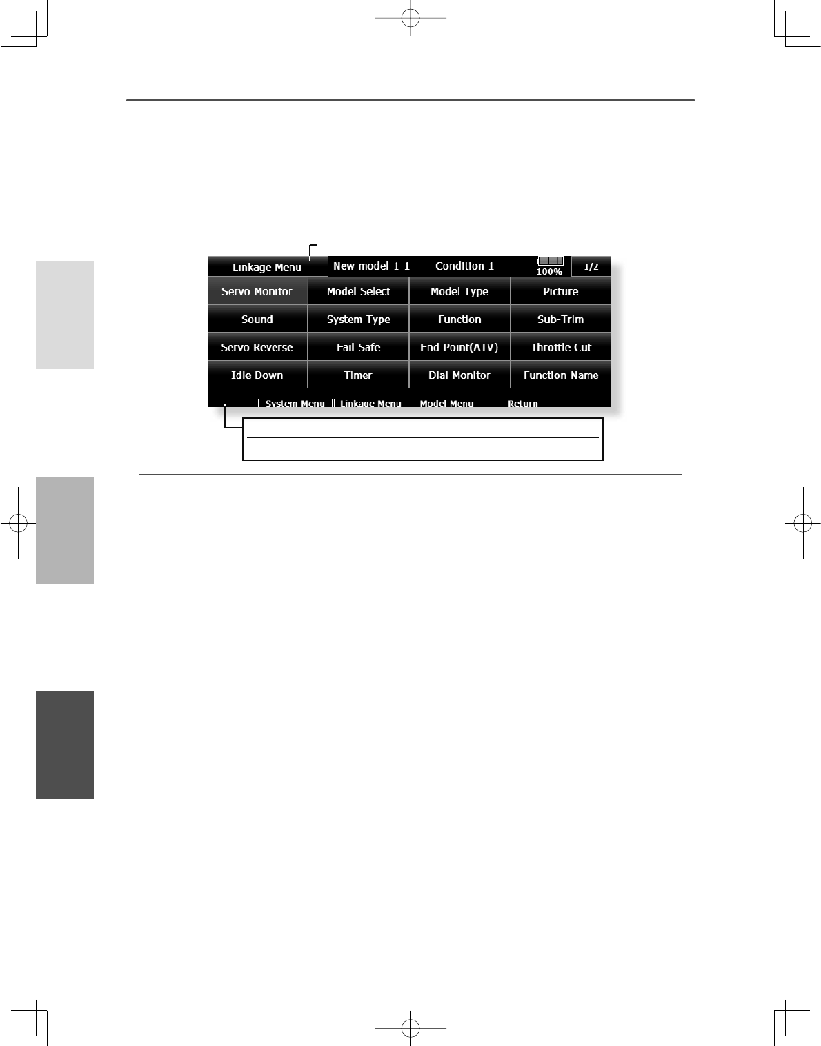
70 <Linkage Menu >
+(/,&237(5
$,53/$1( */,'(5
)81&7,2162)/,1.$*(0(18
The Linkage Menu has all of the functions you
will need to perform model addition, model type
selection, frequency setting, end point setting, and
other model basic settings.
ŏ5HWXUQWR+RPHVFUHHQ
ŏ:KHQ\RXWRXFKWKH/LQNDJH0HQXEXWWRQRQWKHKRPHVFUHHQ WKHPHQX
VKRZQEHORZLVFDOOHGXS7RXFKWKHEXWWRQRIWKHIXQFWLRQ\RXZDQWWRVHW
The functions which can be selected depend on
which model type you are using. A typical menu
screen is shown below.
/LQNDJH0HQXIXQFWLRQVWDEOH
ƔServo Monitor : Displays the servo test and operation position
ƔModel Select : Model addition, call, deletion, copy, model name setting
ƔModel Type : Model type, wing type, switch type, etc. selection
ƔPicture : Picture selection and setting for each model
ƔSound : Sound recording and playback
ƔSystem Type : System selection, receiver link, telemetry.
ƔFunction : Channel assignment of each function can be changed
ƔSub-Trim : Adjusts the neutral position of each servo
ƔServo Reverse : Servo direction reversal
ƔFail Safe : Fail safe function and battery fail safe function setting
ƔEnd Point (ATV) : Servo basic rudder adjustment and limit setting
ƔThrottle Cut : Stops the engine safely and easily (airplane and helicopter only)
ƔIdle Down : Lowers the idle speed of the engine (airplane and helicopter only)
ƔSwash Ring : /LPLWVWKHVZDVKWUDYHOZLWKLQD¿[HGUDQJHWRSUHYHQWOLQNDJHGDPDJHKHOLFRSWHURQO\
ƔSwash : Swash AFR and linkage correction function (helicopter only)
ƔTimer : Timer setting and lap time display
ƔDial Monitor : Dial, slider, and digital trim position display and setting
ƔFunction Name : Function Name can be changed
ƔTelemetry : Displays various data sent from the receiver
ƔSensor : Various telemetry sensors setting
ƔSensor Name : Change of a sensor name
ƔTelemetry Setting : Data logging of telemetry
ƔWarning : Warning sound and vibration setting
ƔData Reset : Model memory data reset (by various item)
Condition Hold function ON/OFF button
)RUDGHWDLOHGGHVFULSWLRQVHHS&RQGLWLRQ+ROGIXQFWLRQ
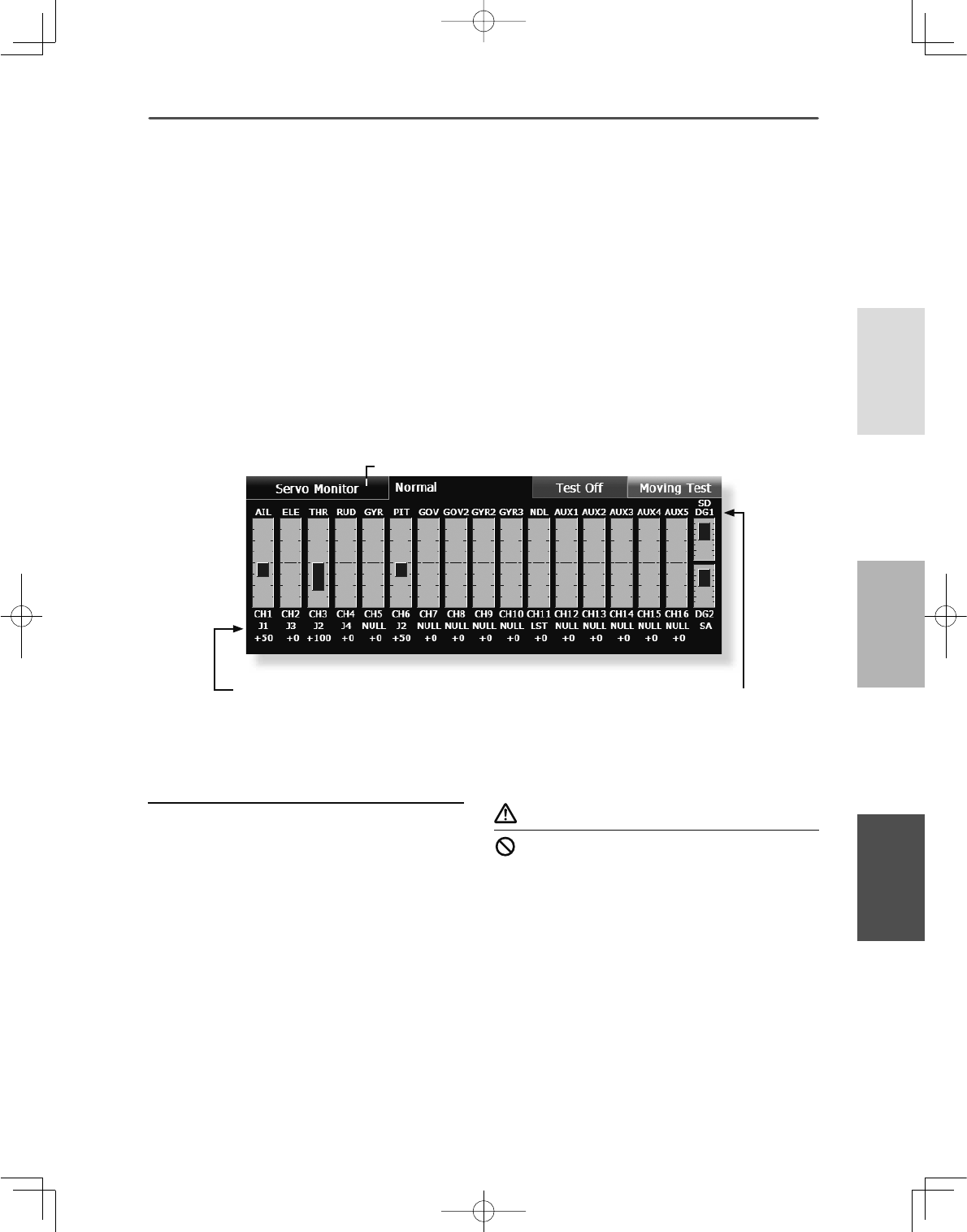
71
<Linkage Menu >
+(/,&237(5
$,53/$1(*/,'(5
6HUYR0RQLWRU 6HUYR7HVW*UDSK'LVSOD\'LVSOD\VVHUYRSRVLWLRQV
This is used for testing servo movement. Touch
“Moving Test” (repetition mode) or “Neutral Test”
IL[HGSRVLWLRQPRGHGHSHQGLQJRQZKLFKRQH
shows on the screen. To get from one to the other,
VLPSO\WRXFKWKH¿HOGDJDLQDQG\RXZLOOPRYHIURP
ŏ5HWXUQWR/LQNDJH0HQX
ŏ7RXFKWKH>6HUYR0RQLWRU@EXWWRQLQWKH/LQNDJH0HQX
WRFDOOWKHVHWXSVFUHHQVKRZQEHORZ
³0RYLQJ7HVW´WR³1HXWUDO7HVW´DXWRPDWLFDOO\1H[W
touch the “Test” on/off button to start testing your
servos. The “Neutral test” is good for finding the
neutral position of a servo horn.
Servo test operation
6HOHFWDWHVWPRGH>0RYLQJ@RU>1HXWUDO@
>5HSHDW@(DFKVHUYRUHSHDWVRSHUDWLRQ
>1HXWUDO@(DFKVHUYRLVORFNHGLQWKHQHXWUDOSRVLWLRQ
:KHQWKH>7HVW2II@EXWWRQLVWRXFKHGWHVWLQJ
EHJLQVLQWKHVHOHFWHGPRGH
&RQWUROQDPH )XQFWLRQQDPH
WARNING
Don't set a servo test mode when the drive motor
is connected and the engine was started.
■Inadvertent rotation of the motor or acceleration of the engine
LVH[WUHPHO\GDQJHURXV
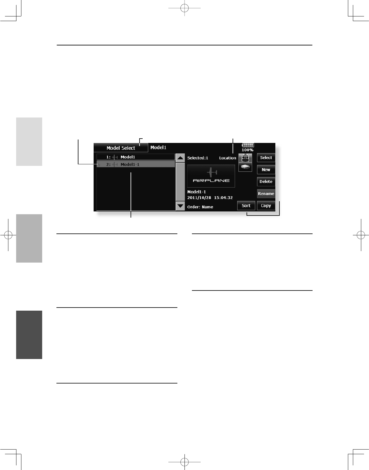
72 <Linkage Menu >
+(/,&237(5
$,53/$1( */,'(5
ŏ5HWXUQWR/LQNDJH0HQX
ŏ&KHFNPDUN
ŏ7RXFKWKH>0RGHO6HOHFW@EXWWRQLQWKH/LQNDJH0HQXWRFDOOWKHVHWXSVFUHHQVKRZQEHORZ
0RGHO6HOHFW 7KH0RGHO6HOHFWLRQIXQFWLRQSHUIRUPVPRGHODGGLWLRQVHOHFWLRQ
GHOHWLRQFRS\DQGPRGHOQDPHVHWWLQJ
This function is used to load the settings of the
desired model into the T18MZ-WC’s memory.
The settings may be selected from either the
transmitter’s built-in memory or a SD card/USB
memory. The name of the model stored in the
transmitter and the SD card/USB memory may be
changed. This can be very useful to tell different
models settings apart. Each model name can be as
long as 32 characters, and the model name always
appears in the display screen.
The Copy function is used to copy one set of model
data into a second memory within the transmitter and
the SD card/USB memory. It may be used for getting
a head-start on setting up models with almost the
VDPHVHWWLQJVRQO\GLIIHUHQFHVQHHGWREHPRGL¿HG
instead of entering the complete model from
scratch). Also, this function may be used to make a
backup copy of a model setup before any changes
are made.
7KHGLVSOD\VFUHHQLVDQH[DPSOH7KHVFUHHQGHSHQGVRQWKHPRGHOW\SH
0RGHOOLVW
Model call
7RXFKWKH/RFDWLRQLFRQDQGVHOHFWWKH
ORFDWLRQWRZKLFKWKHGHVLUHGPRGHOLVWREH
VDYHG
7UDQVPLWWHULFRQ7UDQVPLWWHUPHPRU\
6'FDUGLFRQ6'FDUG
86%PHPRU\LFRQ86%PHPRU\
7RXFKWKHGHVLUHGPRGHOLQWKHPRGHOOLVW
7RXFKWKH>6HOHFW@EXWWRQ
7RXFK><HV@WRFDOOWKHPRGHO:KHQ\RX
ZDQWWRFDQFHOPRGHOFDOOSUHVV>1R@
Model addition
7RXFKWKH>1HZ@EXWWRQ
7RXFK><HV@WRDGGWKHPRGHO:KHQ\RX
ZDQWWRFDQFHOPRGHODGGLWLRQWRXFK>1R@
:KHQDQHZPRGHOLVDGGHGWKH0RGHO7\SH
VFUHHQLVDXWRPDWLFDOO\GLVSOD\HG&KHFNRU
FKDQJHWKHPRGHO,IWKHUHDUHQRFKDQJHVWRXFK
WKH0RGHO7\SHLFRQV
7KHDGGHGPRGHOLVGLVSOD\HGLQWKHPRGHOOLVW
:KHQ0RGHODGGLWLRQDOLQNZLWKDUHFHLYHULV
UHTXLUHG:KHQQRWUHOLQNLQJ DQHZPRGHOFDQW
XVHWHOHPHWU\
Model deletion
7RXFKWKH/RFDWLRQLFRQRUWKHPRGHO\RX
ZDQWWRGHOHWHLQWKHPRGHOOLVW7KHPRGHO
FXUUHQWO\VHOHFWHGFDQQRWEHGHOHWHG
7RXFKWKH>'HOHWH@EXWWRQ
7RXFK><HV@:KHQ\RXZDQWWRVWRSPRGHO
GHOHWLRQWRXFK>1R@
Model name change
6HOHFWWKHPRGHOE\WRXFKLQJWKH/RFDWLRQ
LFRQRUWKHGHVLUHGPRGHOLQWKHPRGHOOLVW
:KHQ>5HQDPH@LVWRXFKHGDNH\ERDUG
DSSHDUVRQWKHVFUHHQ
(QWHUWKHPRGHOQDPHIURPWKLVNH\ERDUG
8SWRFKDUDFWHUV FDQEHLQSXWDWWKH PRGHO
QDPH
Model copy
6HOHFWDPRGHOWRFRS\IURPWKHOLVW
&KHFNPDUNLVDWWDFKHGWRWKHPRGHODQGD
&RS\EXWWRQLVGLVSOD\HGRQWKHULJKW
7RXFKWKH&RS\EXWWRQDQGWRXFKWKH
'HVWLQDWLRQEXWWRQDQGVHOHFWWKHFRS\
VWRUDJHGHVWLQDWLRQ7UDQVPLWWHURU6'FDUG
86%PHPRU\
7RXFKWKHFHQWHU>&RS\@EXWWRQ
:KHQ><HV@LVWRXFKHGFRS\LQJLVH[HFXWHG
:KHQ\RXZDQWWRFDQFHO FRS\LQJWRXFK
>1R@
,IWKHUHLVQR PRGHOZLWKWKHVDPHQDPH LQWKH
FRS\GHVWLQDWLRQWKHQDPH RIWKHFRSLHGPRGHO
LVVDYHG,IWKHUH LVDPRGHORIWKH VDPHQDPHD
QXPEHULVDGGHGDWWKHHQGRIWKHPRGHOQDPH
DQGWKHPRGHOLV FRSLHG<RXFDQFKDQJHWKH
QDPHODWHU
:KHQWKHPRGHOGDWDLVFRSLHGWKHPRGHOGDWHLV
UHVHWWRWKHGDWHWKDWWKHFRS\ZDVGRQH
ŏ/RFDWLRQ
ŏ,WFDQVRUWLQ
RUGHURIWKH
GDWHRUD
QDPH
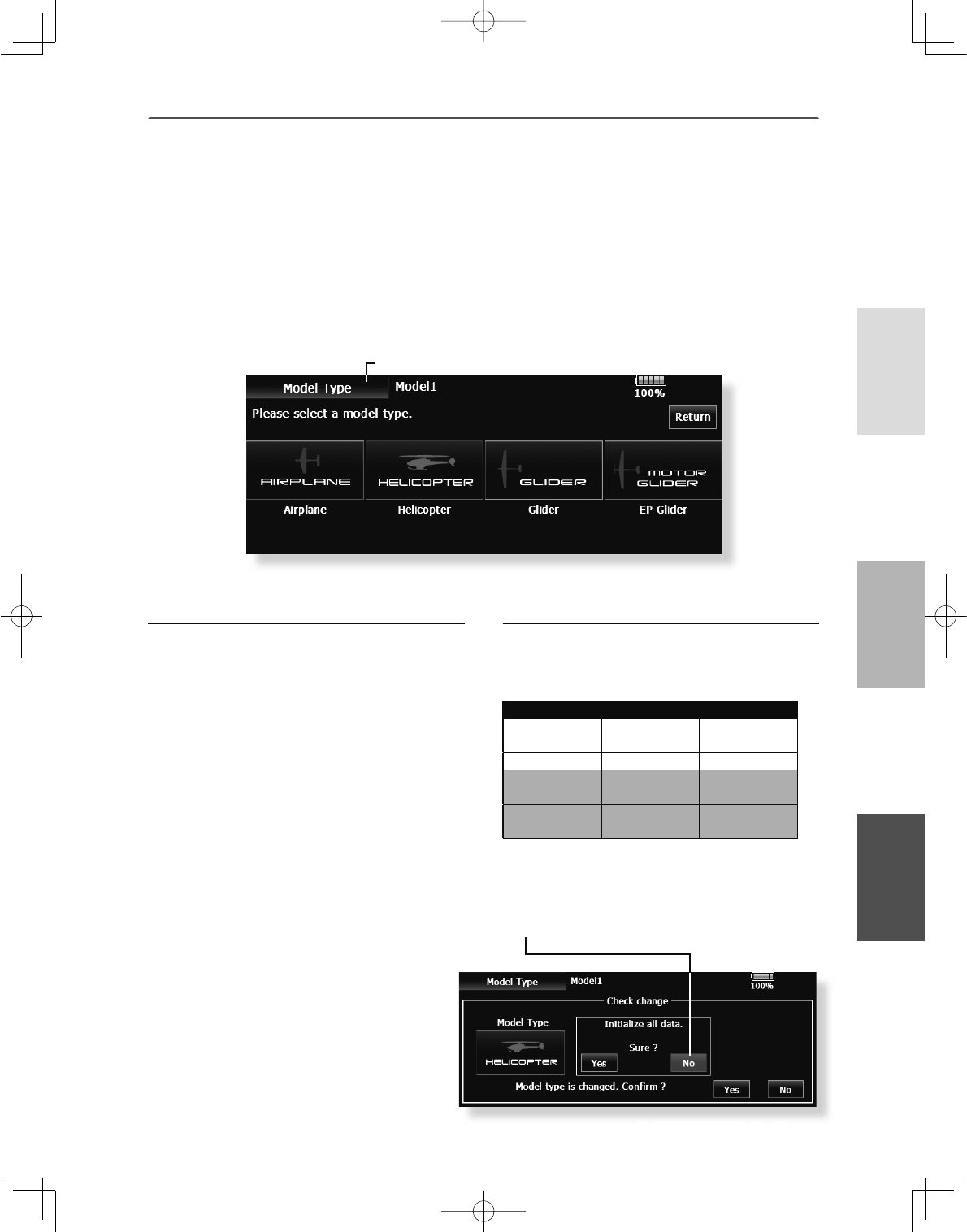
73
<Linkage Menu >
+(/,&237(5
$,53/$1(*/,'(5
ŏ5HWXUQWR/LQNDJH0HQX
ŏ7RXFKWKH>0RGHO7\SH@EXWWRQLQWKH/LQNDJH0HQXWR
FDOOWKHVHWXSVFUHHQVKRZQEHORZ
ŏ:KHQDGDWDFKDQJHZLOORFFXUWKHFRQÀUPDWLRQ
VFUHHQRIGDWDLQLWLDOL]DWLRQPHQXZLOOEHGLVSOD\HG
$SXVKRQ>\HV@ZLOOLQLWLDOL]HGDWDDQGDOORZFKDQJHV
$SXVKRQ>QR@ZLOOVWRSGDWDFKDQJHV
0RGHO7\SH 7KLVIXQFWLRQDOORZV\RXWRVHOHFWWKHPRGHOW\SHIURPDPRQJDLUSODQH
KHOLFRSWHUDQGJOLGHU
7KHGLVSOD\VFUHHQLVDQH[DPSOH7KHVFUHHQGHSHQGVRQWKHPRGHOW\SH
Seven types of main wings and three types of tail
wings are available for airplanes. Eight swash types
are available for helicopters. Seven types of main
wings and three types of tail wings are available for
JOLGHUV)XQFWLRQVDQGPL[LQJQHFHVVDU\IRUHDFK
model type are set in advance at the factory.
Note: 7KH0RGHO7\SHIXQFWLRQ DXWRPDWLFDOO\VHOHFWV
WKHRSWLPDORXWSXWFKDQQHOVFRQWUROIXQFWLRQVDQG
PL[LQJIXQFWLRQVIRUWKHFKRVHQPRGHOW\SH:KHQWKH
0RGHO7\SH6HOHFWLRQLVDFFHVVHGDOORIVHWWLQJVLQWKH
DFWLYHPRGHODUHFOHDUHG%HVXUHWKDW\RXGRQ·WPLQG
ORVLQJWKLVGDWDRU EDFNLWXSWRPHPRU\XVLQJWKH
FRS\LQJIXQFWLRQV
Model type selection
6HWWKH0RGHOW\SH:LQJW\SH7DLOW\SHRU
6ZDVKW\SHE\XVLQJWKHDSSURSULDWHEXWWRQ
6HWWKHW\SH\RXFKRRVHE\WRXFKLQJ><HV@DW
WKHFRQILUPDWLRQVFUHHQ:KHQ\RXZDQWWR
FDQFHOPRGHOW\SHVHOHFWLRQWRXFK>1R@
Date changes after a swash type change
'DWDWKDWKDVEHHQVHWPD\FKDQJHLIWKHVZDVK
W\SHRI\RXUKHOLFRSWHULVFKDQJHG
5HIHUWRWKHIROORZLQJWDEOH:KHQGDWDLV
FKDQJHGWKH>VZDVKVHWWLQJ@VFUHHQLVLQLWLDOL]HG
Before After Data taking over
H-1, H-2, HE3,
HR3, HN3, H-3 H-1, H-2, HE3,
HR3, HN3, H-3 OK
++; ++; OK
H-1, H-2, HE3,
HR3, HN3, H-3 ++; NG
++; H-1, H-2, HE3,
HR3, HN3, H-3 NG
73
<
Li
k
M
>
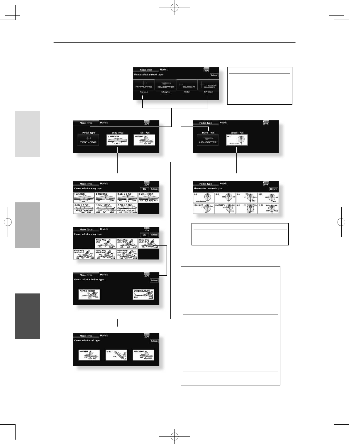
74 <Linkage Menu >
+(/,&237(5
$,53/$1( */,'(5
Model type
Select the model type from
among airplane, helicopter,
glider, and motor glider.
ŏ0RGHOW\SHVHOHFWLRQ
(Airplane, glider) (Helicopter)
ŏ:LQJW\SHVHOHFWLRQ
ŏ:LQJW\SHVHOHFWLRQ
ŏ5XGGHUW\SHVHOHFWLRQ
ŏ6ZDVKW\SHVHOHFWLRQ
ŏ7DLOW\SHVHOHFWLRQ
Wing type (1/2) (Normal)
Select from among :
DLOHURQDLOHURQVDLOHURQVÀDS
DLOHURQVÀDSVDLOHURQVÀDSV
DLOHURQVÀDSVDLOHURQVÀDSV
Wing type (2/2) (Tail-less wing)
Selection from among:
DLOHURQVDLOHURQVÀDS
DLOHURQVÀDSVDLOHURQVÀDSV
DLOHURQVÀDSVDLOHURQVÀDSV
*For Tail-less wing, the rudder type can be selected
from normal rudder and winglet.
Tail type
Select from normal, V tail, and elevator.
Helicopter swash type
6HOHFWIURPDPRQJ++++(
+5+1+DQG+;
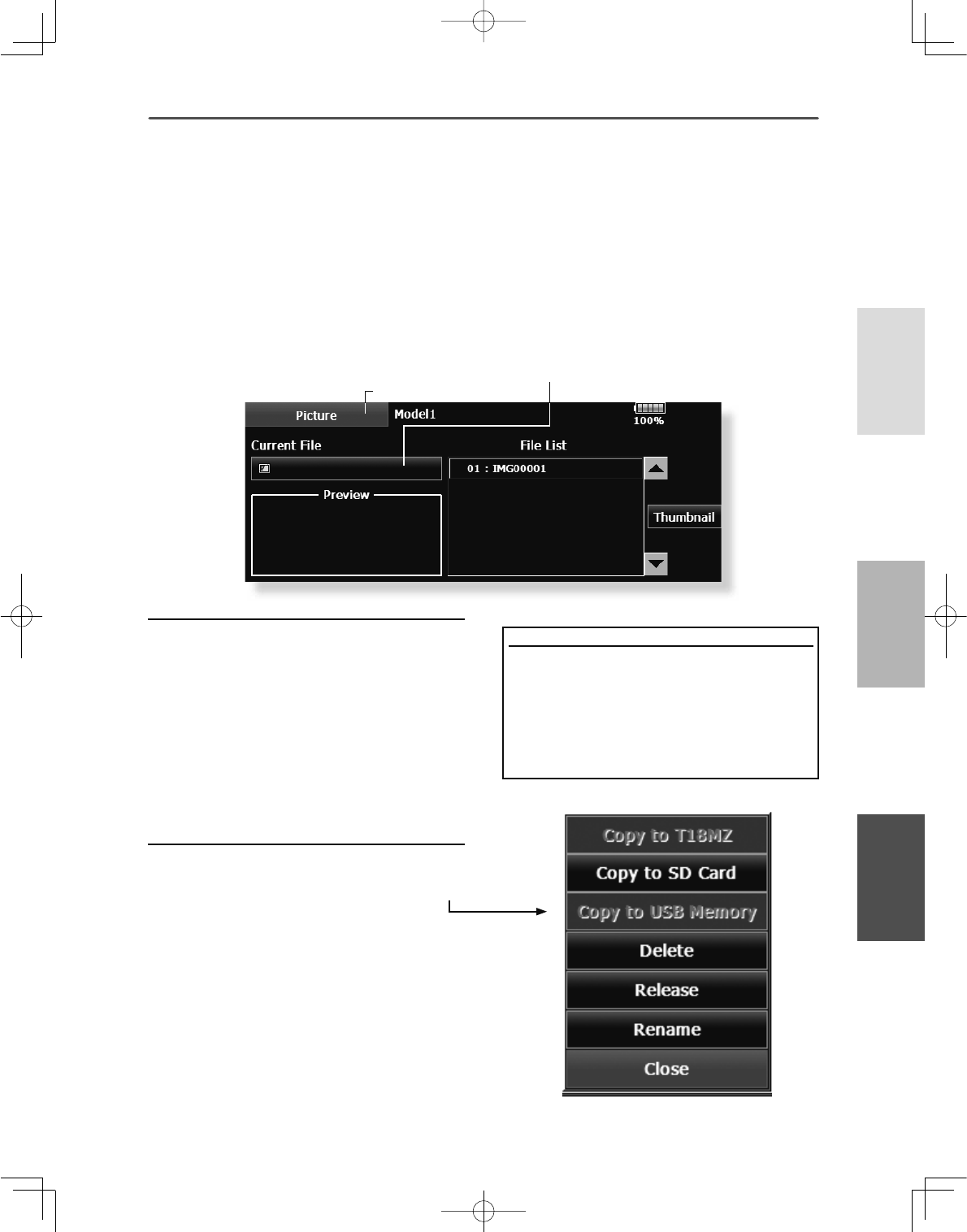
75
<Linkage Menu >
+(/,&237(5
$,53/$1(*/,'(5
ŏ5HWXUQWR/LQNDJH0HQX
ŏ7RXFKWKH>3LFWXUH@EXWWRQLQWKH/LQNDJH0HQXWRFDOO
WKHVHWXSVFUHHQVKRZQEHORZ
3LFWXUH $SLFWXUHRQWKHKRPHVFUHHQFDQEHVHWIRUHDFKPRGHO6LPSOLILHV
LGHQWLÀFDWLRQRIWKHPRGHOGDWDGXULQJVFUHHQRSHUDWLRQ
A photograph of the model taken with a T18MZ-WC
camera, digital camera or other file can be pasted
as the screen display data for each model. This is
convenient in identifying models with the same
model name.
7KHSLFWXUH¿OHVZKLFKFDQEHGLVSOD\HGRQWKHVFUHHQDUHVL]H
[SL[HOVILOHW\SHEPSELWPDSSLFWXUHDQG-3(*
¿OHV,ID¿OHODUJHUWKDQ[LVXVHGWKHSLFWXUHGLVSOD\HG
ZLOOEHUHGXFHG$ODUJHU¿OHWKDQ[SL[HOVFDQQRWEH
used.
When a picture is pasted, it is displayed as a screen
image in the following screens:
ŏ0RGHO6HOHFWVFUHHQ
ŏ+RPHVFUHHQ
ŏ6WDUWXSVFUHHQ
Pasting a picture
3LFWXUHGDWDLVVHWWRWKHPRGHOPHPRU\FXUUHQWO\LQ
XVH
<RXFDQFKRRVHWR XVHDSLFWXUHWKDWLV VDYHGLQ
WKHVHSODFHV70=:&6'FDUG86%PHPRU\
6HOHFWWKHSLFWXUHIURPWKHÀOHOLVWE\WRXFKLQJ
WKHGHVLUHGSLFWXUHGDWD
%HIRUHVHOHFWLRQWRXFKWKHVFUROOEXWWRQDWWKH
WRSRUERWWRPRI WKH7KXPEQDLODQGFRQILUPWKH
FRQWHQWVRIWKHSLFWXUHWREHVDYHGE\WKHSUHYLHZ
VFUHHQ
7RSDVWHWKHSLFWXUHWRXFK><HV@:KHQ\RX
ZDQWWRFDQFHOSDVWLQJWRXFK>1R@
Copy / Delete / Release / Rename of picture
6HOHFWWKHSLFWXUHIURPWKH>7KXPEQDLO@E\
WRXFKLQJWKHGHVLUHGSLFWXUHGDWD
7RSDVWHWKHSLFWXUHWRXFKWKLVVFUHHQLV
GLVSOD\HG
&RS\70=:&6'FDUG86%PHPRU\
'HOHWH5HOHDVH5HQDPHRUVHOHFWLRQ
5HOHDVH,WORVHVIURP&XUUHQW)LOH
'HOHWH3LFWXUHGDWDLVGHOHWHG
6HOHFWWKHSLFWXUHIURP WKHWKXPEQDLOPHPRU\
FDUGRU0=:&LFRQV \RXZLVKWRFRS\IRU WKDW
SDUWLFXODUPRGHO3UHVV(QWHU DQGH[LWRXWWRWKH
KRPHSDJH
1H[WVHOHFW><HV@RU>1R@6HOHFW5HQDPHWR
QDPHWKHSLFWXUHRI\RXUFKRLFHZLWKWKH
DSSHDUHGNH\ERDUG:KHQILQLVKHGSUHVV
5HWXUQ
[Important]
Before reading data from the PC, insert the SD
card/USB memory into the transmitter and turn on
the power. The following folders are automatically
ZULWWHQ7RUHDGD¿OHIURPWKH3&FRS\WKH¿OHWR
DIROGHUE\¿OHW\SH
ŏ%033LFWXUHÀOH ŏ:$9$XGLRÀOH
ŏ:0$0XVLFÀOH ŏ02'(/0RGHOGDWD
ŏ7KHQDPHRIWKHSDVWHGSLFWXUHLV
GLVSOD\HG
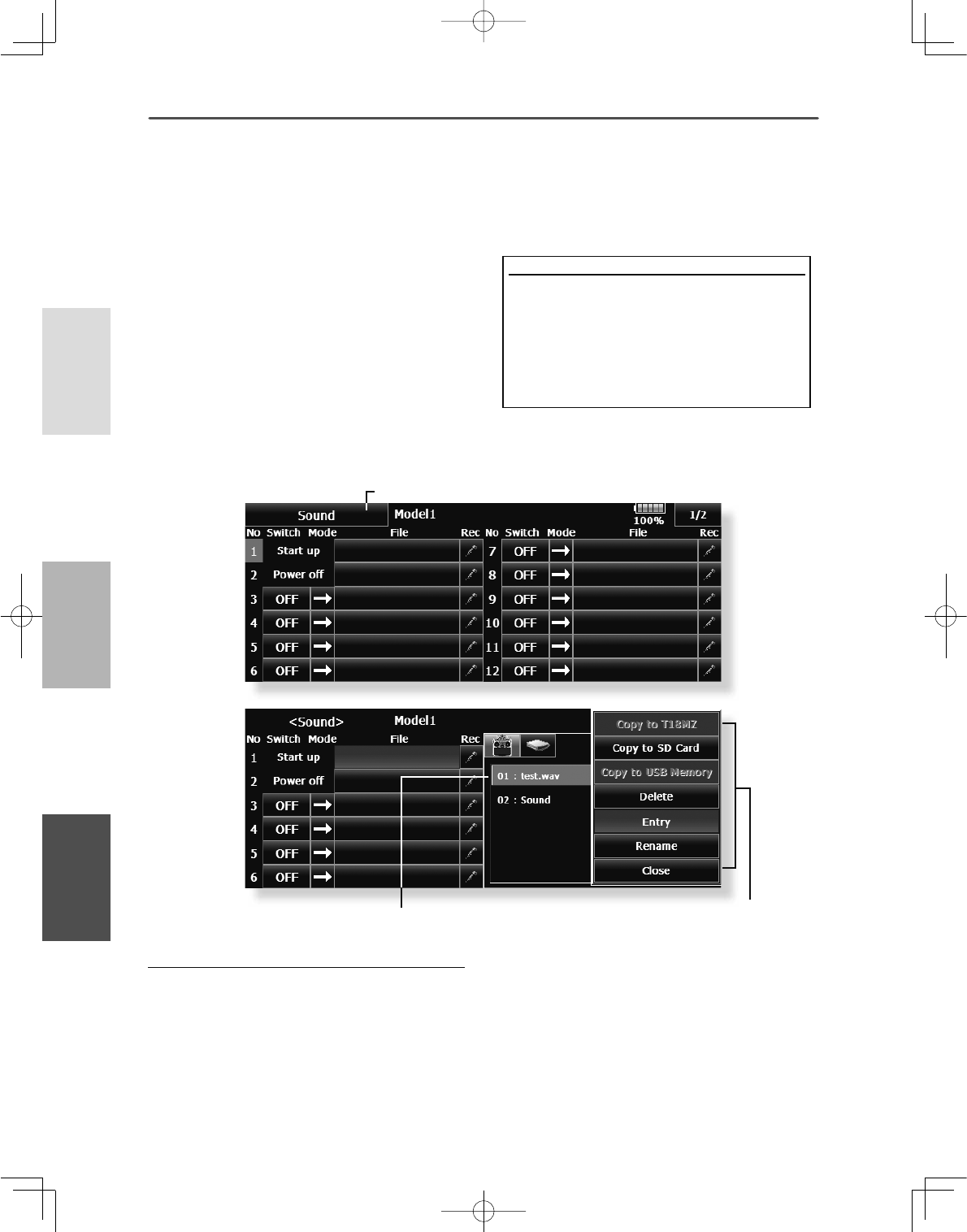
76 <Linkage Menu >
+(/,&237(5
$,53/$1( */,'(5
ŏ5HWXUQWR/LQNDJH0HQX
ŏ7RXFKWKH>6RXQG@EXWWRQLQWKH/LQNDJH0HQX
WRFDOOWKHVHWXSVFUHHQVKRZQEHORZ
ŏ7RXFKWKHÀOHEXWWRQ&RS\'HOHWH
(QWU\5HQDPHLVPDGH
,WLVWKHVDPHSURFHGXUHDVWKHSLFWXUH
RIWKHSUHFHGLQJFODXVH
6RXQG 6RXQGUHFRUGLQJDQGSOD\EDFN
6DYHGVRXQG¿OH
[Important]
Before reading data from a PC, insert the SD
card/USB memory into the transmitter and
turn on the power. The following folders are
automatically written. When reading a file from
WKH3&FRS\LWWRDIROGHUE\¿OHW\SH
ŏ%033LFWXUHÀOH ŏ:$9$XGLRÀOH
ŏ:0$0XVLFÀOH ŏ02'(/0RGHOGDWD
Sounds recorded with the microphone built into the
WUDQVPLWWHURUDQ\DXGLR¿OHVZDYFDQEHVHWWRWKH
power switch or any preset switch that you choose.
2QO\DZDY¿OHVDYHGLQWKHVDPHVWRUDJHSODFH70=:&
SD card, a USB memory) as the current model can be chosen.
7KHPD[LPXPUHFRUGLQJWLPHIURPWKHPLFURSKRQHLV
VHFRQGV7ZHQW\IRXUDXGLR¿OHVFDQEHVDYHG
7KHRQO\DXGLR¿OHW\SHZKLFKFDQEHUHFRUGHGLVZDY2QO\
the sounds recorded with the built-in microphone or an audio
¿OHVDYHGIURP\RXU3&WRDQ6'FDUGFDQEHSOD\HGEDFN
6HWXSVFUHHQVQXPEHUWRFDQEHLQGLYLGXDOO\
assigned to audio file switches, etc. The playback
files can be switched each time the same switch is
operated. This can be used when playing back the
name of maneuvers, etc.
>6RXQGVWDUWLQJ@
:KHQWUDQVPLWWHUSRZHUVZLWFKWXUQHGRQ
:KHQWUDQVPLWWHUSRZHUVZLWFKWXUQHGRII
a6ZLWFKFDQEHVHW
Voice Recording
7RXFKDQ\5(&EXWWRQWRFDOOXSWKH6281'
5(&25'(5VFUHHQ
7RXFKWKH5(&EXWWRQWRVWDUWUHFRUGLQJ
5HFRUGLQJWLPHVHFRQGV
5HFRUG\RXUYRLFHDV\RXDUHIDFLQJWKH
WUDQVPLWWHU·VPLFURSKRQH
6SHDNORXGO\DQGFOHDUO\
7RILQLVKSUHVV´&/26(µ$OVRVRXQGILOHV
FUHDWHGE\\RXU3&PD\EHSOD\HGEDFNE\
DVVLJQHGVZLWFKHV)LOHW\SHVZDYÀOHRQO\
$YRLFHÀOHLVVDYHG DXWRPDWLFDOO\WRWKHORFDWLRQ
RIWKHPRGHO\RX DUHFXUUHQWO\XVLQJ:KHWKHU
LQWKHWUDQVPLWWHU6'FDUGRU86%PHPRU\$ÀOH
QDPHLVGLVSOD\HGRQWKHÀOHEXWWRQFRUUHVSRQGLQJ
WRDUHFRUGLQJEXWWRQ
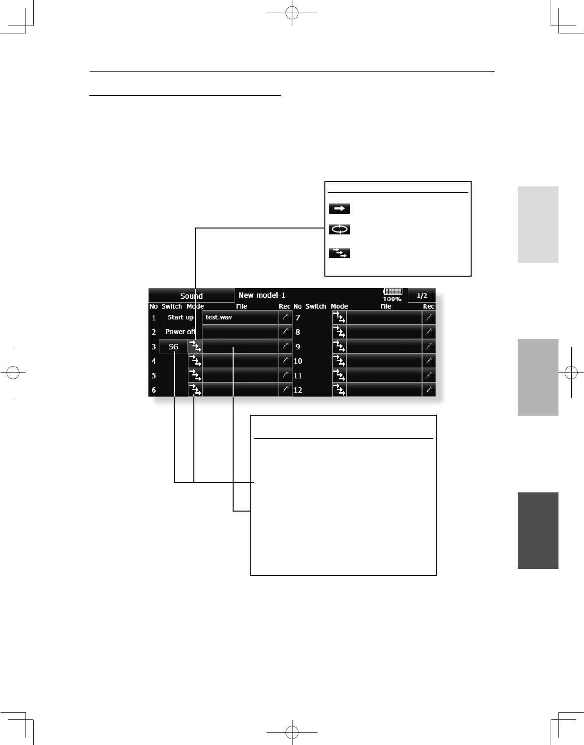
77
<Linkage Menu >
+(/,&237(5
$,53/$1(*/,'(5
$VVLJQPHQWRIDXGLR¿OHVWRVZLWFKHV
$XGLRÀOHVFDQEHVDYHGEHIRUHKDQG
7RXFKWKHÀOHEXWWRQRIWKHQXPEHU\RXZDQW
WRVHW$OLVWRIWKHÀOHVVWRUHGLVGLVSOD\HG
6HOHFWWKHDXGLRILOH\RXZDQWWRSOD\EDFN
IURPWKHOLVWRIDXGLRÀOHV
6LQFHWKHDXGLRILOHV DUHSOD\HGEDFNZKHQWKH
DXGLRILOHQDPHVLQWKHOLVWDUHWRXFKHGWKHILOH
FRQWHQWVFDQEHFKHFNHGEHIRUHDVVLJQPHQW
7RXFKWKH>)LOH@EXWWRQWRDVVLJQWKHÀOHV
6ZLWFKHVDUHDOVRVHOHFWHGIRUQXPEHUa
7RXFKWKH>18//@EXWWRQWRFDOOWKHVZLWFK
VHOHFWVFUHHQ
6HTXHQWLDOO\SOD\LQJEDFNUHJLVWHUHG¿OHHDFK
time operated by 1 switch
This is used when calling the order of maneuvers,
etc.
>6HWWLQJPHWKRG@
$IWHUVHOHFWLQJWKHVZLWFKSUHVVWKH>ń@
EXWWRQ7KHEXWWRQGLVSOD\WKHUHDIWHULV
VZLWFKHGDVVKRZQLQWKHVFUHHQDERYH
$VVLJQWKHDXGLRÀOHVLQWKHRUGHULQZKLFK
\RXZDQWWRSOD\WKHPEDFN
The audio files are played back each time the
switch selected by the above setting is turned on.
6HOHFWWKHVZLWFKDQGLWV21GLUHFWLRQDWWKH
VZLWFKVHOHFWVFUHHQ
)RUDGHWDLOHGGHVFULSWLRQRIWKHVHOHFWLRQPHWKRG
VHHVZLWFKVHWWLQJPHWKRGDWWKHEDFNRIWKLV
PDQXDO
Mode button
3OD\LQJEDFNUHJLVWHUHGILOH
RQO\RQFH
3OD\LQJEDFNUHJLVWHUHGILOH
UHSHDWHGO\
6HTXHQWLDOO\SOD\LQJEDFN
UHJLVWHUHGILOHHDFKWLPH
RSHUDWHGE\VZLWFK
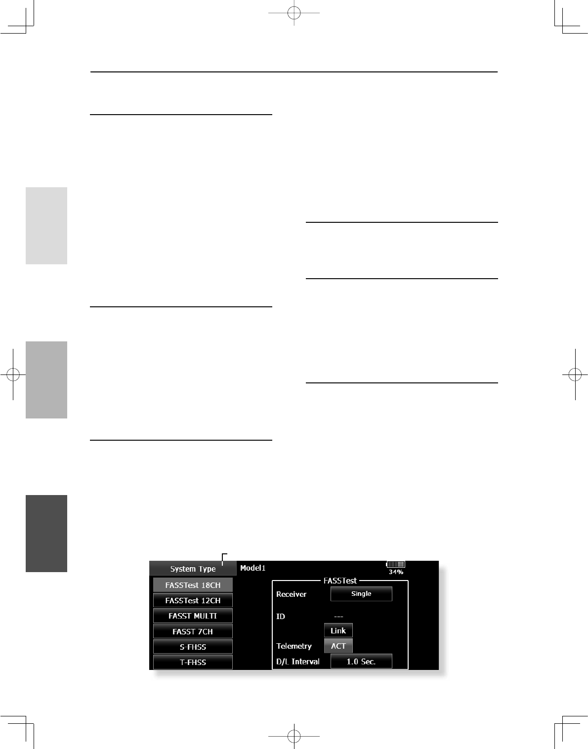
78 <Linkage Menu >
+(/,&237(5
$,53/$1( */,'(5
System Type selection
7KH70=:&LVIRU*+]RQO\7KHV\VWHP
can be changed from among 5 choices: FASSTest
18CH, FASSTest 12CH, FASST MULTI, FASST
7CH, S-FHSS, T-FHSS. Select the system
matched to the type of receiver you are using.u
*Even if it changes a system type, other model data is not
reset.e
*If a system type is changed in the case of a helicopter, It
can choose out of two channel orders.
[Yes] : Selection sets the channel order suitable for system
type. (We recommend here.)
[No] : The present channel order is maintained.
*All control surfaces should be checked for the correct
operating directions and operating smoothness before
À\LQJWKHPRGHO
$QDORJVHUYRVFDQQRWEHXVHGZLWKWKH56%LQWKH
FASSTest 12CH mode.
Receiver linking
The receiver will only be controlled (without
being affected by other transmitters) by the
transmitter it is linked to. When using a receiver
other than one purchased as a set, linking is
necessary.
Moreover, a re-link is required when a new model
is added by model selection, and the time of
system type change.
Dual receiver function (only FASSTest 18CH
mode)
Dual receivers can be linked with the T18MZ-
:&7ZRUHFHLYHUVDUHUHFRJQL]HGLQGLYLGXDOO\
E\,'QXPEHUV)RUH[DPSOHLQ56%&+
output setting function is used, by setting the
¿UVWDVDV&+DQGVHWWLQJWKHVHFRQGDV
ŏ5HWXUQWR/LQNDJH0HQX
ŏ7RXFKWKH>6\VWHP7\SH@EXWWRQLQWKH/LQNDJH
0HQXWRFDOOWKHVHWXSVFUHHQVKRZQEHORZ
6\VWHP7\SH 6\VWHPPRGHVHWWLQJ5HFHLYHUOLQN
&+WZRVHWVRIUHFHLYHUVFDQEHXVHGDVDVHW
in the model, allowing you 16 channels. If a dual
receiver function is used, the following function can
set up individually.
・Battery fail-safe voltage setup
A telemetry function cannot be used for the 2nd
receiver. 7KHYROWDJHDQG([WYROWDJHRIDQG
receiver cannot be known with a transmitter.
Telemetry function (only FASSTest mode)
To use the telemetry function, set “Telemetry” to
“ON”.
D/L Interval (only FASSTest mode)
When a telemetry function is enabled, the receiving
interval (down-link interval) of sensor data can be
changed.
If a D/L interval is increased, the response of
the sensor data display becomes slower, but stick
response will improve.
Battery fail-safe voltage setup (FASSTest /
T-FHSS mode)
The voltage which battery fail-safe activates, can
EHVHWZKHQ\RXOLQN97KHUHFHLYHU
PHPRUL]HVWKHVHWWLQJDVLWZDVDWOLQN
Suggested setting voltages are as follows.
FHOOV1L&GRU1L0+1RUPDOY Y
FHOOV/L)H1RUPDOY aY
FHOOV/L3R1RUPDOY aY
It is a rough reference value.
Since it changes with servos carried in the condition
and the model of a battery, please set to your own
model in a battery consumption current.
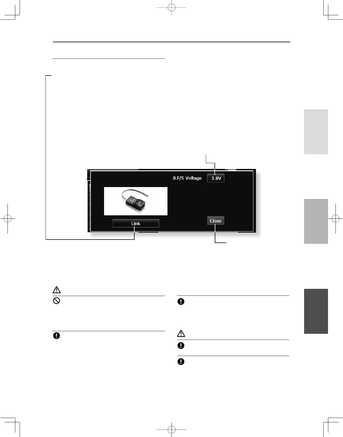
79
<Linkage Menu >
+(/,&237(5
$,53/$1(*/,'(5
WARNING
Do not perform the linking operation when the
drive motor is connected and the engine was
started.
■Inadvertent rotation of the motor or acceleration of the engine
LVH[WUHPHO\GDQJHURXV
Once the link operation is complete, please
check that your receiver can be operated with the
linked transmitter.
CKHFNRSHUDWLRQVXI¿FLHQWO\EHIRUHÀ\LQJDIWHU
linking.
■If the same receiver is sending in the vicinity, there is the
danger that the transmitter may be linked with that receiver.
CAUTION
Always turn on the transmitter power after
linking is complete.
When pairing with the transmitter, be sure that a
previously linked transmitter is not transmitting
Linking method (T18MZ-WC ↔R7008SB)
%ULQJWKHUHFHLYHUWREHOLQNHGWRZLWKLQFP
RIWKHWUDQVPLWWHU
3UHVVWKH>/LQN@EXWWRQLQWKH>/LQN@ER[RI
>6\VWHP7\SH@
7KHWUDQVPLWWHUHPLWVDFKLPHVRXQGDQG
HQWHUVWKHOLQNPRGH
7KHUHFHLYHUSRZHULVLPPHGLDWHO\WXUQHG
RQ$ERXWVHFRQGVDIWHUWKHSRZHULVWXUQHG
RQWKHUHFHLYHUHQWHUVWKHOLQNLQJVWDWH
5HFHLYHUOLQNLQJWLPHLVDERXWVHFRQG
,IOLQNLQJLVVXFFHVVIXOWKHUHFHLYHU/('FKDQJHV
IURPUHGWRJUHHQWKHOLQNPRGHHQGVDQG
WKHUHFHLYHU,'FRGHLVGLVSOD\HG
,IOLQNLQJIDLOVDQHUURUPHVVDJHLVGLVSOD\HG
%ULQJWKHWUDQVPLWWHUFORVHUWRWKHUHFHLYHUDQG
UHSHDWWKHSURFHGXUHDERYHIURPVWHS
'RQRWSHUIRUPWKHOLQNLQJRSHUDWLRQZKHQWKH
GULYHPRWRULVFRQQHFWHGRUWKHHQJLQHLVUXQQLQJ
:KHQ\RXXVHWZRUHFHLYHUVSOHDVHEHVXUHWR
VHWXSDSULPDU\DQG VHFRQGDU\LQWKHGXDO
PRGH
6LQFHWZRVHWVRIUHFHLYHUVFDQQRWEHLQGLYLGXDOO\
UHFRJQL]HGZLWKRXWXVLQJDSULPDU\DQG
VHFRQGDU\VHWXSLWLVLPSRVVLEOHWRUHFHLYH
WHOHPHWU\GDWDFRUUHFWO\
<RXPXVWOLQN RQHUHFHLYHUDWDWLPH,IERWK
SRZHUVXSSOLHVWRWKH UHFHLYHUVDUHVZLWFKHGRQ
VLPXOWDQHRXVO\GDWDLVUHFHLYHG LQFRUUHFWO\E\
WKHWUDQVPLWWHU
$WHOHPHWU\IXQFWLRQ FDQQRWEHXVHGIRUWKH QG
UHFHLYHU
<RXFDQQRWOLQNWKUHHVHWVRIUHFHLYHUV
/LQNLVUHTXLUHGZKHQDV\VWHPW\SHLVFKDQJHG
/LQNLVUHTXLUHGZKHQDQHZPRGHOLVPDGHIURPD
PRGHOVHOHFWLRQ
ŏ7RXFKWKH>/LQN@EXWWRQLQWKH6\VWHP7\SH
0HQXWRFDOOWKHVHWXSVFUHHQVKRZQEHORZ
ŏ%DWWHU\IDLOVDIHYROWDJHVHWXSRQO\
)$667HVWPRGH
ŏ5HWXUQWR6\VWHP7\SH
0HQX
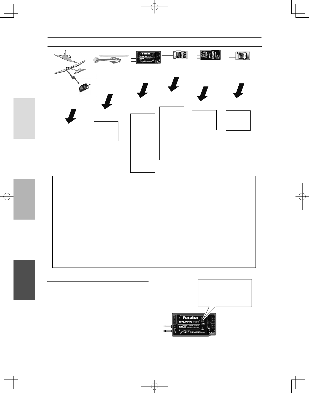
80 <Linkage Menu >
+(/,&237(5
$,53/$1( */,'(5
-Response speed has
priority over number
of channels
-Telemetry requires
only the current
receiver battery
-Want to use a
previously used
receiver as is
-Want to use a
miniature receiver
for indoor planes -Want to use an
S-FHSS system
miniature receiver
-Want to use an
T-FHSS system
receiver
FASSTest 18CH
FASSTest 12CH
FASST MULTI FASST 7CH S-FHSS
R608FS
R6008HS
R6108SB
R6208SB
R6014HS
R6014FS
R6203SB
R6203SBE
R6202SBW
R6303SB
R6303SBE
R7008SB
R7003SB
R7018SB
R617FS
R6004FF
R616FFM
R6106HF
R6106HFC
R6203SB
R6203SBE
R6202SBW
R6303SB
R6303SBE
R2006GS
R2106GF
R2008SB
R7008SB
R7003SB
R7018SB
(Usable receivers)
-Want to use more channels
-Want to use a large number
of telemetry functions
(The time of august, 2015)
T-FHSS Air
R3006SB
R3008SB
-Want to use a large
number of telemetry
functions
The example for choosing System Type
Receiver link method in FASST and S-FHSS
If the receiver of FASST and S-FHSS is used, the
methods of a link differ.
%ULQJWKHWUDQVPLWWHUDQGWKHUHFHLYHUFORVHWR
HDFKRWKHUZLWKLQLQFKHVKDOIPHWHU
7XUQRQWKHWUDQVPLWWHU
7XUQRQWKHUHFHLYHU
3UHVVDQGKROGWKH/LQNVZLWFKPRUHWKDQ
WZRVHFRQGV:KHQWKHOLQNLVFRPSOHWH
WKH/('LQWKHUHFHLYHUFKDQJHVWRVROLG
JUHHQ:KHQWKH,'FDQQRWEHUHDGGXHWR
WKHVXUURXQGLQJHQYLURQPHQWWU\UHDGLQJLW
ZLWKWKHWUDQVPLWWHUDQGUHFHLYHUDQWHQQDV
WRXFKHG
*Follow the manual of the receiver to be used.
Moreover, carry out an operating check.
System type
■ FASSTest 18CH ---
■ FASSTest 12CH ---
■ FASST MULTI ---
■ FASST 7CH --- FASST-7CH system receiver mode. Up to 7 channels can be used.
■ T-FHSS Air ---
■ S-FHSS --- S-FHSS system receiver mode. Up to 8 channels can be used.
FASSTest system receiver mode. Applicable with the telemetry sensor unit. Up
to 18 channels (linear 16+ON/OFF2) can be used.
T-FHSS system receiver mode. Applicable with the telemetry sensor unit. Up to
18 channels (linear 16+ON/OFF2) can be used.
FASSTest system receiver mode. Applicable with receiver voltage display. Up to
12 channels (linear10+ON/OFF2) can be used. Telemetry Sensor cannot be used,
but the response speed is faster than that of the 18CH mode.
FASST-MULTI system receiver mode. Up to 18 channels (linear 16+ON/OFF2)
can be used.
• Analog servos cannot be used with the R7008SB in the FASSTest 12CH mode.
,QFDVHRI
)$6676)+66D/LQN
EXWWRQRIWKHUHFHLYHULV
SUHVVHGIRUDOLQN
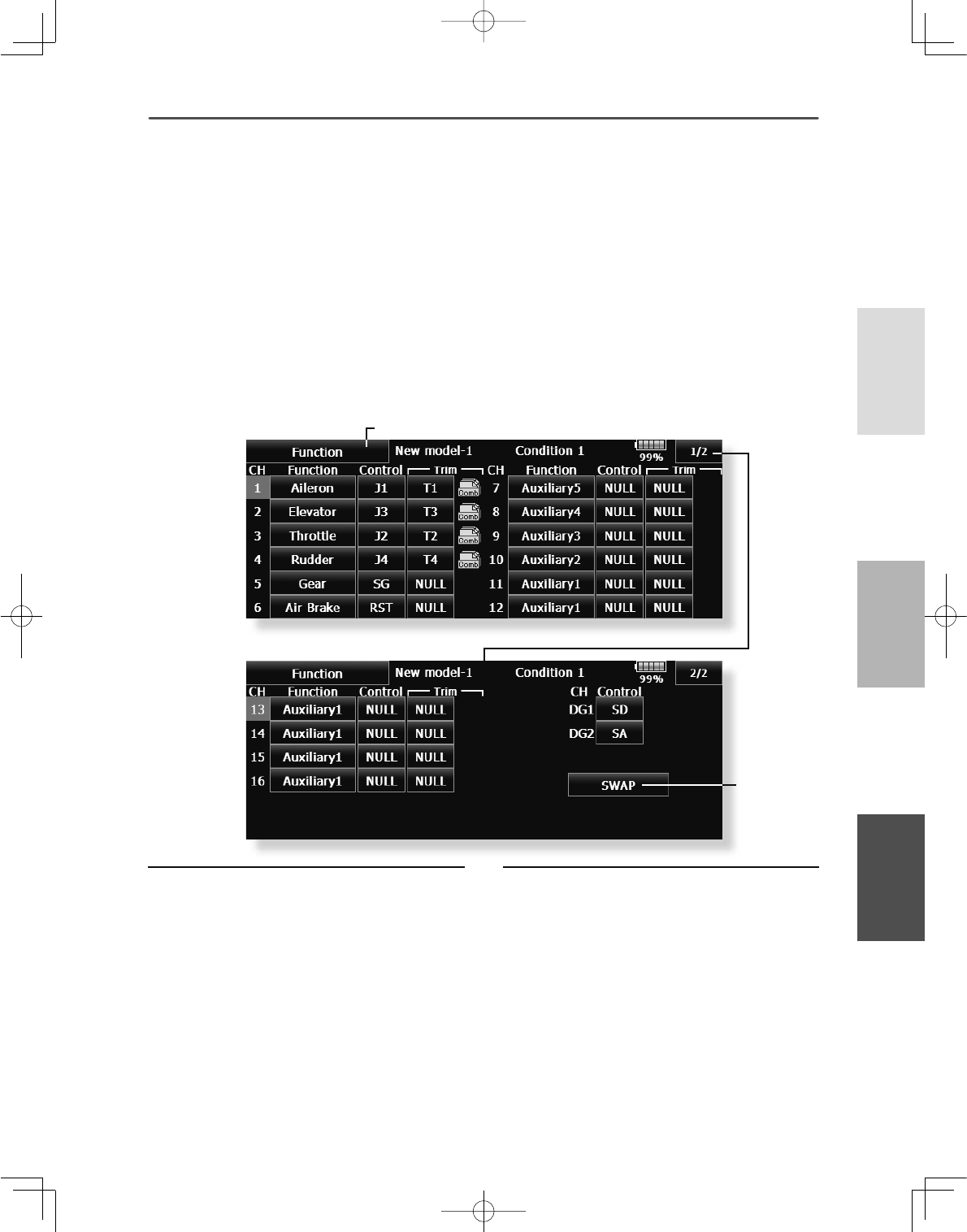
81
<Linkage Menu >
+(/,&237(5
$,53/$1(*/,'(5
ŏ5HWXUQWR/LQNDJH0HQX
ŏWR>6:$3@
ŏ7RXFKWKH>)XQFWLRQ@EXWWRQLQWKH/LQNDJH
0HQXWRFDOOWKHVHWXSVFUHHQVKRZQEHORZ
)XQFWLRQ &KDQQHODVVLJQPHQWIRUHDFKIXQFWLRQFDQEHFKDQJHGWRVXLW\RXUQHHGV
When you select model and wing (swash) types, you
ZLOOILQGWKDWWKHRSWLPL]HGFRPELQDWLRQVRIVHUYR
output channels and functions have been already
preset. If you would like, on the function-setting
screen of the linkage menu, you can freely change
combinations of servo output channels, functions
(aileron, elevator, etc), and input controllers (sticks,
switches, trim levers and trim switches). You can
also assign the same function to multiple servo
output channels such as assigning elevator function
to CH2 and CH3.
7KHGLVSOD\VFUHHQLVDQH[DPSOH7KHVFUHHQGHSHQGVRQWKHPRGHOW\SH
Function change
7RXFKWKHIXQFWLRQEXWWRQRIWKHFKDQQHO\RX
ZDQWWRFKDQJHWRFDOOWKHIXQFWLRQOLVW
6HOHFWWKHIXQFWLRQ\RXZDQWWRFKDQJH
7RXFK><HV@7KHGLVSOD\UHWXUQVWRWKHRULJLQDO
VFUHHQ:KHQ\RXZDQWWRFDQFHOIXQFWLRQ
FKDQJHWRXFK>1R@
0XOWLSOHFKDQQHOVFDQEHDVVLJQHGWRIXQFWLRQ
0XOWLSURSLVDQRSWLRQDO REMHFWIRU0XOWLSURS
GHFRGHUV
&+ZKLFKFDQEH0XOWLSURSVHWXS!
)$667HVW&+7)+66&+
)$667HVW&+QRWVHW
)$66708/7,&+
)$667&+QRWVHW
6)+66QRWVHW
DG1, DG2 (switch channels)
These two channels can be used as switch (On/
Off) channels. You can freely change combinations
between servo output channels and input controllers
(sticks, switches, trim levers and trim switches).
Channel restrictions by a System Type
FASSTest 18CH/T-FHSS---16 CH+2 Switch
)$667HVW&+&+6ZLWFK
FASST MULTI ---16 CH+2 Switch
FASST 7CH --- 7 CH
S-FHSS --- 8 CH
Operation control change
7RXFKWKHFRQWUROEXWWRQRIWKHFKDQQHO\RX
ZDQWWRFKDQJH$FRQWUROVHOHFWVFUHHQVWLFN
VZLWFKNQREWULPOHYHUHWFLVGLVSOD\HG
6HOHFWWKHFRQWURO\RXZDQWWRRSHUDWH
7RXFK>&ORVH@7KHGLVSOD\UHWXUQVWRWKH
SUHFHGLQJVFUHHQ
7KHVDPHFRQWUROFDQEHDVVLJQHGWRPXOWLSOH
FKDQQHOV
82 <Linkage Menu >
+(/,&237(5
$,53/$1( */,'(5
7KHGLVSOD\VFUHHQLVDQH[DPSOH7KHVFUHHQGHSHQGVRQWKHPRGHOW\SH
Trim change
7RXFKWKHWULPEXWWRQWRFDOOWKHWULPVHWXS
VFUHHQ
7KHIROORZLQJLWHPVFDQEHVHWDWWKHWULP
VHWXSVFUHHQ
ŏ+DUGZDUHVHWWLQJ6HOHFWLRQRIVZLWFKHWF
ZKLFKFRQWUROVWULP7KHVHOHFWVFUHHQLVFDOOHG
E\WRXFKLQJWKH>+:6HOHFW@EXWWRQ
ŏ5DWHVHWWLQJ
ŏ2SHUDWLRQVWHSVHWWLQJ
ŏ7ULPPRGHVHWWLQJ
1RUPDOPRGH1RUPDOWULPOLQHDURSHUDWLRQ
SWAP
If [SWAP] is pushed, it will call up the following
screen. You can easily change two separate functions,
keeping the data that was set for each channel.
6HOHFWWKH7ULPEXWWRQIRUWKHWZRIXQFWLRQV
\RXVHOHFWHGWR6ZDSWRVHWXSWKHWULPV
DSSURSULDWHO\
,I>2.@LVSXVKHGWZRFKDQQHOVZLOO
LQWHUFKDQJH
,WFDQFKRRVHRQO\WRWZR
$7/PRGH$7/RSHUDWLRQPRGH:RUNVDWRQO\RQH
HQGRIRSHUDWLRQ5HYHUVHLVDOVRSRVVLEOH
&750PRGH0D[LPXPFKDQJHQHDUFHQWHUE\
FHQWHUWULPRSHUDWLRQ'RHVQRWFKDQJHDWHQGRI
WKHVWLFNPRYHPHQW
ŏ6HSDUDWHFRPELQDWLRQPRGH7ULPGDWDFDQ
EHVHWWRGLIIHUHQWÁLJKWFRQGLWLRQV
6HSDUDWHPRGH7ULPDGMXVWPHQWIRUHDFKVHSDUDWH
ÁLJKWFRQGLWLRQ
83
<Linkage Menu >
+(/,&237(5
$,53/$1(*/,'(5
ŏ5HWXUQWR/LQNDJH0HQX
ŏ7RXFKWKH>6XE7ULP@EXWWRQLQWKH/LQNDJH0HQX
WRFDOOWKHVHWXSVFUHHQVKRZQEHORZ
6XE7ULP 6HWWLQJRIQHXWUDOSRVLWLRQRIHDFKVHUYR
7KHGLVSOD\VFUHHQLVDQH[DPSOH7KHVFUHHQGHSHQGVRQWKHPRGHOW\SH
The Sub-Trim function is used to set the servo
neutral position, and may be used to make fine
adjustments to the control surface after linkages and
pushrods are hooked up. When you begin to set up
a model, be sure that the digital trims are set to their
center position.
Sub trim adjustment
7RXFKWKHWULPGLVSOD\SDUWRIWKHFKDQQHO\RX
ZDQWWRDGMXVW
$GMXVWPHQWEXWWRQVDSSHDUVRQWKH 6XE7ULP
PHQXVFUHHQ
8VHWKHDGMXVWPHQWEXWWRQVWRDGMXVWWKHVXE
WULP
ŏ,QLWLDOYDOXH
ŏ$GMXVWPHQWUDQJHaVWHSV
6HHDERYH
5HSHDWWKLVVWHSIRUHDFKFKDQQHO
84 <Linkage Menu >
+(/,&237(5
$,53/$1( */,'(5
ŏ5HWXUQWR/LQNDJH0HQX
ŏ7RXFKWKH>6HUYR5HYHUVH@EXWWRQLQWKH/LQNDJH
0HQXWRFDOOWKHVHWXSVFUHHQVKRZQEHORZ
6HUYR5HYHUVH 8VHWRUHYHUVHWKHVHUYRWKURZGLUHFWLRQ
7KHGLVSOD\VFUHHQLVDQH[DPSOH7KHVFUHHQGHSHQGVRQWKHPRGHOW\SH
Servo Reverse changes the direction of an individual
servo’s response to a control stick movement.
For CCPM helicopters, be sure to read the section
on Swash AFR before reversing any servos. With
CCPM helicopters, always complete your servo
reversing prior to any other programming. If you
XVHSUHEXLOW$LUSODQH*OLGHUIXQFWLRQVWKDWFRQWURO
multiple servos, it may be confusing to tell whether
the servo needs to be reversed or a setting in the
function needs to be reversed. See the instructions
IRUHDFKVSHFLDOL]HGIXQFWLRQIRUIXUWKHUGHWDLOV
Servo reversing procedure
After setting up a new model, be sure to define all
special menus. Be sure that all servos are plugged
into the proper receiver channels. Now, determine
whether you need to reverse any channels by
moving each stick and observing the corresponding
movement in the model’s controls.
7RXFKWKHGHVLUHGFKDQQHO·VVHWWLQJEXWWRQWR
FKRRVHWKHSURSHUGLUHFWLRQIRUWKHVHUYR
7RXFK´<HVµLQWKHQH[WVFUHHQ
5HSHDWIRUHDFKVHUYRQHHGLQJUHYHUVDO
:KHQGRQHWRXFK´6HUYR5HYHUVHµWRUHWXUQ
WRWKH/LQNDJH0HQX
Always check servo direction prior to every flight
DVDQDGGLWLRQDOSUHFDXWLRQWRFRQ¿UPSURSHUPRGHO
memory, hook ups, and radio function.
WARNING
Before a flight, always check that your models
servo operation, the direction of control surfaces,
and switch setup are correct.
Default setting of the motor channel is always
reverse.
85
<Linkage Menu >
+(/,&237(5
$,53/$1(*/,'(5
ŏ5HWXUQWR/LQNDJH0HQX
ŏ7RXFKWKH>)DLO6DIH@EXWWRQLQWKH/LQNDJH
0HQXWRFDOOWKHVHWXSVFUHHQVKRZQEHORZ
)DLO6DIH 6HWVWKHVHUYRVRSHUDWLQJSRVLWLRQZKHQWUDQVPLWWHUVLJQDOVFDQQRORQJHUEH
UHFHLYHGRUZKHQWKHUHFHLYHUEDWWHU\YROWDJHGURSV
7KHGLVSOD\VFUHHQLVDQH[DPSOH7KHVFUHHQGHSHQGVRQWKHPRGHOW\SH
The Failsafe function is used to set up positions
that the servos will move to in the case of radio
LQWHUIHUHQFH'H¿QHVVHUYRSRVLWLRQZKHQVLJQDOVDUH
lost and when receiver battery voltage becomes low.
You may set either of two positions for each channel:
Hold, where the servo maintains its last commanded
position, or fail safe, where each servo moves to a
predetermined position. You may choose either mode
for each channel.
The T18MZ-WC system also provides you with an
advanced battery monitoring function that warns
you when the receiver battery has only a little power
remaining. In this case, each servo is moved to the
defined failsafe position. The battery failsafe may
EHUHOHDVHGE\RSHUDWLQJDSUHGH¿QHGFRQWURORQWKH
transmitter (default is throttle). Do not continue
to fly, land as soon as possible. Remember, if the
Fail safe setting procedure
Decide which channels you want to go to preset
positions, and which ones you want to maintain
their last commanded position. To select the fail safe
mode you wish to set, use the F/S button. This button
toggles between the two modes. (Hold, F/S)
F/S mode setting:
7RXFKWKH)6EXWWRQRIWKHFKDQQHO\RXZDQW
WRVHWDQGVHWWKDWFKDQQHOWRWKH>)6@PRGH
+ROGWKHFRUUHVSRQGLQJVWLFNFRQWUROVOLGHU
RURWKHUFRQWUROLQWKHSRVLWLRQ\RXZDQWWKH
VHUYRWRPRYHWRZKHQWKHIDLOVDIHIXQFWLRQLV
DFWLYDWHGDQGWRXFKWKH)6SRVLWLRQEXWWRQ
7KDWSRVLWLRQLVGLVSOD\HGLQSHUFHQWDJH
:KHQ\RXZDQWWRUHWXUQWKDWFKDQQHOWRWKH+ROG
PRGHWRXFKWKH>)6@EXWWRQDJDLQ
Battery fail safe setting procedure
To select the B.F/S mode, touch the [B.F/S] button.
Each time the button is touched, it toggles between
[OFF] and [B.F/S].
predefined control suddenly moves to a position
you did not command, land at once and check your
receiver battery.
Do not continue to fly, land as soon as possible.
Defines servo position when signals are lost and
when receiver battery voltage becomes low.
WARNING
For safety, always set the fail safe functions.
■Especially set the throttle channel fail safe function so that
WKHVHUYRPRYHVWRWKHPD[LPXPVORZVLGHIRUDLUSODQHVDQG
to the slow side from the hovering position for helicopters.
Crashing of the model at full high when normal radio waves
cannot be received due to interference, etc., is very dangerous.
■If fail safe is reset by throttle stick movement, the fail safe
may be mistaken as an engine malfunction and will be reset
DWORZWKURWWOHDQGWKHPRGHOZLOOFRQWLQXHWRÀ\,I\RXKDYH
any doubts, immediately land.
B.F/S setting:
7RXFKWKH>%)6@EXWWRQRIWKHGHVLUHG
FKDQQHOWRVHWLWWRWKH%)6PRGH
+ROGWKHFRUUHVSRQGLQJVWLFN95VOLGHURU
RWKHUFRQWUROLQWKHSRVLWLRQ\RXZDQWWKH
VHUYRWRPRYHWRZKHQWKHEDWWHU\IDLOVDIH
IXQFWLRQLVDFWLYDWHGDQGWRXFKWKH)6
SRVLWLRQEXWWRQ7KLVSRVLWLRQLVGLVSOD\HGLQ
SHUFHQWDJH
:KHQ\RXZDQWWR UHWXUQWKDWFKDQQHOWR2))
WRXFKWKH>%)6@EXWWRQDJDLQ
Battery Fail safe Release Function
This function releases the predefined control from
it's held position after indicating that your receiver
battery is low.
(QWHUWKHFRQWUROVHWWLQJ VFUHHQE\WRXFKLQJ
WKH%DWWHU\)65HOHDVHEXWWRQ1RZ\RXPD\
FKRRVHZKHWKHUPRYLQJWKHWKURWWOHUHVHWV
WKHFRQGLWLRQRUVHOHFWDVWLFNRUVZLWFKWR
GHDFWLYDWHLW7RVHWDGHVLUHGWKURWWOHUHOHDVH
SRVLWLRQPRYHWKHWKURWWOHVWLFNWRWKHSRLQWDW
ZKLFK\RXZLVKWKH%)6WREHUHOHDVHG
ŏ7R6ZLWFK!
VFUHHQ
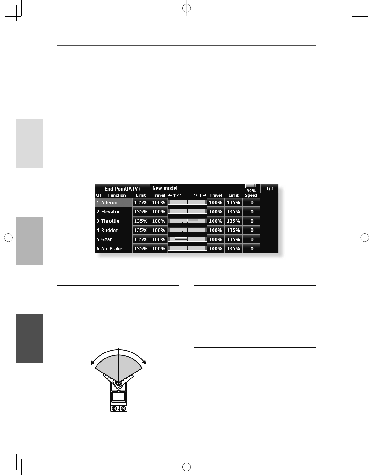
86 <Linkage Menu >
+(/,&237(5
$,53/$1( */,'(5
ŏ5HWXUQWR/LQNDJH0HQX
ŏ7RXFKWKH>(QG3RLQW$79@EXWWRQLQWKH/LQNDJH
0HQXWRFDOOWKHVHWXSVFUHHQVKRZQEHORZ
(QG3RLQW$79 6HWVWKHWUDYHOOLPLWSRLQWDQGVSHHGRIHDFKVHUYR
7KHGLVSOD\VFUHHQLVDQH[DPSOH7KHVFUHHQGHSHQGVRQWKHPRGHOW\SH
The End Point function adjusts the left and right
servo throws, generates differential throws, and will
correct improper linkage settings.
The travel rate (normal full stick movement at high
UDWHVFDQEHYDULHGIURPWRLQHDFK
direction on channels 1 to 16. Also, the limit point
KRZIDUWKHVHUYRWUDYHOVZKHQDPL[LVLQYROYHG
ZKHUHVHUYRWKURZVWRSVPD\EHYDULHGIURPWR
Servo travel adjustment
7RXFKWKHWUDYHOEXWWRQRIWKHFKDQQHO\RX
ZDQWWRVHW$GMXVWPHQWEXWWRQVDSSHDURQ
WKHVFUHHQ
8VHWKHVHEXWWRQVWRDGMXVWWKHUDWH
ŏ,QLWLDOYDOXH
ŏ$GMXVWPHQWUDQJHa
5HSHDWWKHSURFHGXUHDERYHIRUHDFKUDWH
Limit point adjustment
7RXFKWKHOLPLWEXWWRQRIWKHFKDQQHO\RX
ZDQWWRVHW
8VHWKHDGMXVWPHQWEXWWRQVWRDGMXVWWKHOLPLW
SRLQW
ŏ,QLWLDOYDOXH
ŏ$GMXVWPHQWUDQJHa
5HSHDWWKLVSURFHGXUHIRUHDFKOLPLWSRLQW
Note: The indicators on the screen display actual servo throw
of the each channel. The center position of the indicator is
based on the Sub-Trim settings. Therefore the Sub-Trim
adjustment changes the Limit point display of the indicator.
The Servo Speed setting is used to set the servo delay for
each channel, from channel l to channel 16. The system uses
the programmed speed (delay) to slow down servo position
FKDQJHV7KH6HUYR6SHHGVHWWLQJFDQEHYDULHGIURPWR
in each channel.
Servo speed setting
7RXFKWKH6SHHGEXWWRQRIWKHFKDQQHO\RX
ZDQWWRVHW
8VHWKHDGMXVWPHQWEXWWRQVWRDGMXVWWKHVHUYR
VSHHG
ŏ,QLWLDOYDOXH
ŏ$GMXVWPHQWUDQJHaVWHSV
5HSHDWWKLVSURFHGXUHIRUHDFKFKDQQHO
7RFORVHWKLVVFUHHQWRXFKWKH>(QG3RLQW$79@
EXWWRQ
30 ∼
140% 30 ∼
140%
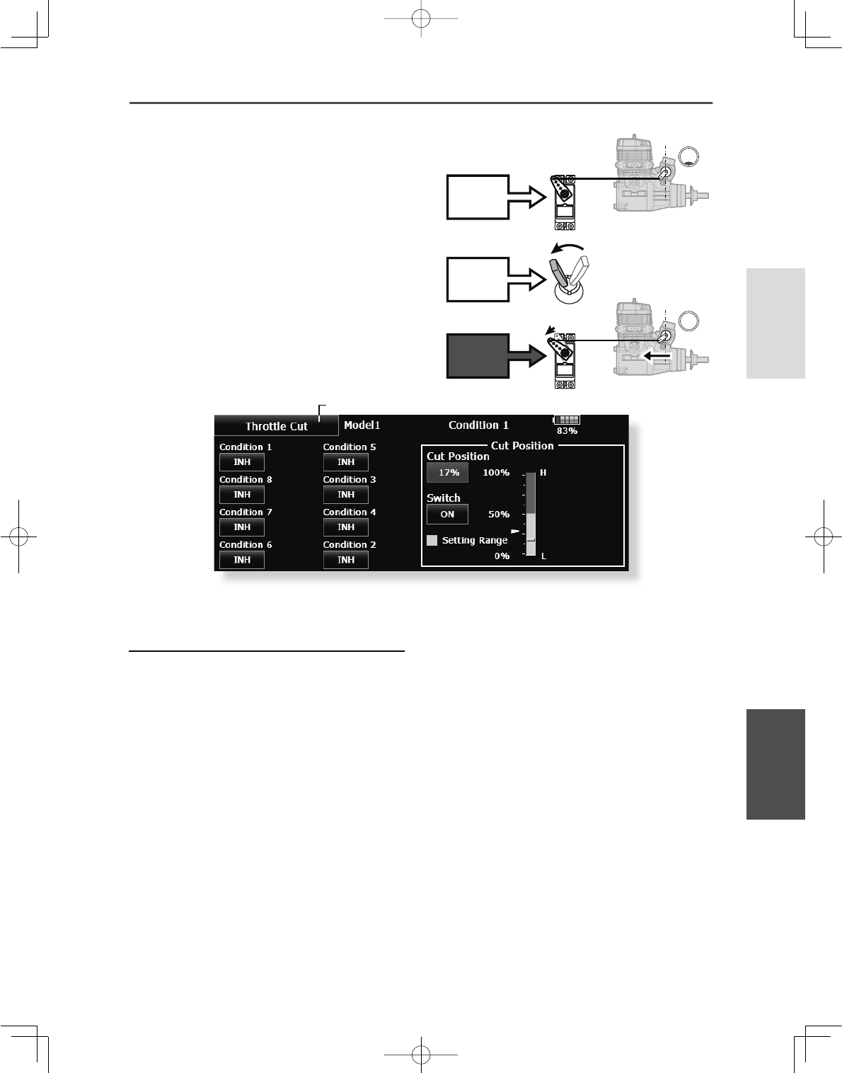
87
<Linkage Menu >
+(/,&237(5
$,53/$1(*/,'(5
ŏ5HWXUQWR/LQNDJH0HQX
ŏ7RXFKWKH>7KURWWOH&XW@EXWWRQLQWKH/LQNDJH0HQX
WRFDOOWKHVHWXSVFUHHQVKRZQEHORZ
7KURWWOH&XW 6WRSVWKHHQJLQHVDIHO\DQGHDVLO\DLUSODQHDQGKHOLFRSWHURQO\
7KHGLVSOD\VFUHHQLVDQH[DPSOH7KHVFUHHQGHSHQGVRQWKHPRGHOW\SH
Throttle cut provides an easy way to stop the engine,
by flipping a switch with the throttle stick at idle.
The action is not functional at high throttle to avoid
accidental dead sticks. The switch’s location and
direction must be chosen, as it defaults to NULL.
Throttle cut setting procedure
7RVHWXSWKURWWOHFXWLQFRQGLWLRQVVHOHFWWKH
FRQGLWLRQQXPEHUDQGWRXFKWKH,1+EXWWRQ
7KURWWOHFXWIXQFWLRQVZLWFKVHWWLQJ
7RXFKWKH18//EXWWRQWRFDOOWKH6ZLWFK!
VFUHHQDQGWKHQVHOHFWWKHVZLWFKDQGLWV21
GLUHFWLRQ
)RUDGHWDLOHGGHVFULSWLRQRIWKHVHOHFWLRQ
PHWKRGVHH>6ZLWFK6HWWLQJ0HWKRG@DWWKH
EDFNRIWKLVPDQXDO
7KURWWOHFXWSRVLWLRQVHWWLQJ
6HWWKHWKURWWOHVWLFNWRPD[LPXPVORZDQG
WRXFKWKHFXW3RVLWLRQEXWWRQ$GMXVWPHQW
EXWWRQVDSSHDU$WWKHVDPHWLPHWKH
QXPHULFDOYDOXHRIWKHFXUUHQWPD[LPXPVORZ
VLGHLVGLVSOD\HGDW&XW3RVLWLRQ
8VHWKHDGMXVWPHQWEXWWRQVWRDGMXVWWKH
VHUYRWUDYHOZKHQWKHWKURWWOHFXWIXQFWLRQLV
DFWLYDWHG
ŏ,QLWLDOYDOXH
ŏ$GMXVWPHQWUDQJHa
:LWKWKURWWOHVWLFNDW LGOHDGMXVWWKHUDWHXQWLO WKH
HQJLQHFRQVLVWHQWO\VKXWVRII EXWWKURWWOHOLQNDJHLV
QRWELQGLQJ:KHQÀQLVKHGWRXFKWKH7KURWWOH&XW
EXWWRQWRH[LW
7RH[LWWKHVHWWLQJWRXFKWKH>7KURWWOH&XW@
EXWWRQ
Note: When conditions are set, at Throttle cut setup can
be performed for each condition. Throttle cut can only be
DFWLYDWHGLQDVSHFL¿FFRQGLWLRQLI\RXKDYHVHOHFWHGDQGVHW
up this function within the condition. When using throttle cut
in a specific condition, and ON or active. If you change to
another condition, throttle cut is canceled and no longer active
LQWKH¿UVWFRQGLWLRQDVORQJDVWKHVHFRQGFRQGLWLRQGRHVQRW
have throttle cut active.
Cut
Switch
Cut
Idle
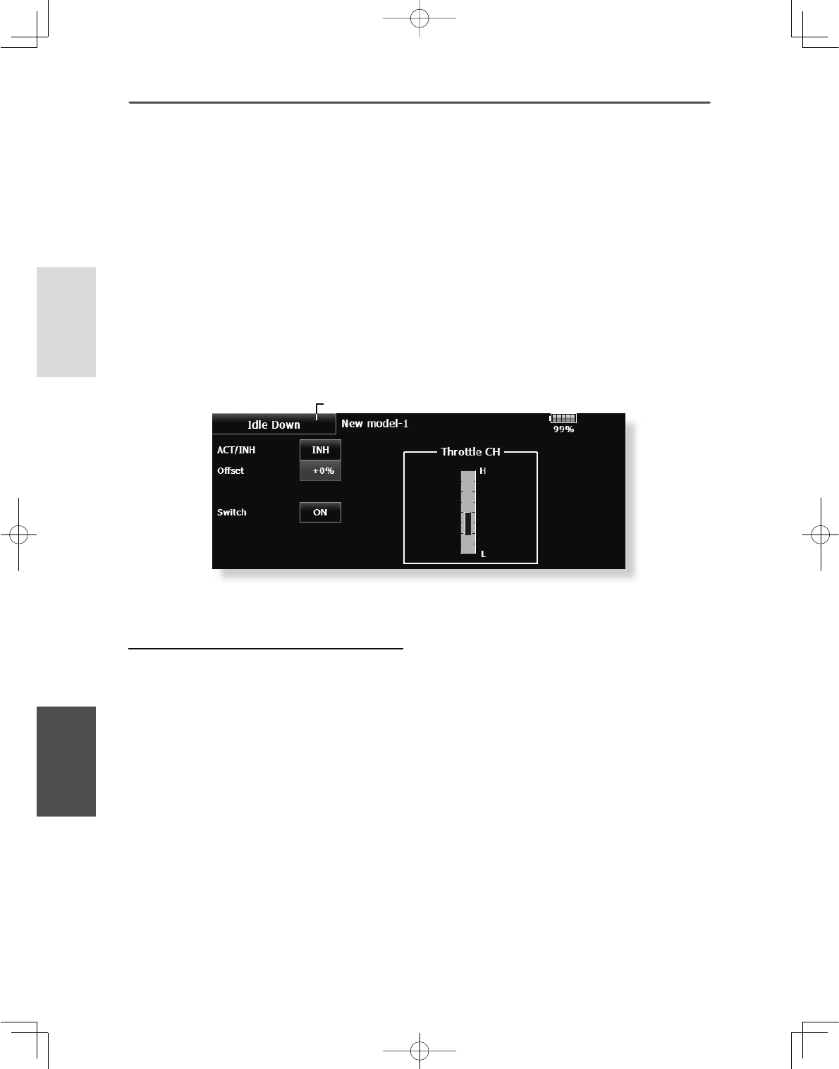
88 <Linkage Menu >
+(/,&237(5
$,53/$1( */,'(5
ŏ5HWXUQWR/LQNDJH0HQX
ŏ7RXFKWKH>,GOH'RZQ@EXWWRQLQWKH/LQNDJH0HQX
WRFDOOWKHVHWXSVFUHHQVKRZQEHORZ
,GOH'RZQ /RZHUVWKHHQJLQHLGOLQJVSHHGDLUSODQHDQGKHOLFRSWHURQO\
7KHGLVSOD\VFUHHQLVDQH[DPSOH7KHVFUHHQGHSHQGVRQWKHPRGHOW\SH
The idle down function lowers the engines idle by
ÀLSSLQJDVZLWFKZLWKWKHWKURWWOHVWLFNDWLGOH7KH
action is not functional at high throttle to avoid
accidental dead sticks. The switch’s location and
direction must be chosen, as it defaults to NULL.
Idle down setting procedure
7RXFKWKH,1+EXWWRQWRDFWLYDWHWKHLGOH
GRZQIXQFWLRQ
,GOHGRZQIXQFWLRQVZLWFKVHWWLQJ
7RXFKWKH18//EXWWRQWRFDOOWKH6ZLWFK!
VFUHHQDQGWKHQVHOHFWWKHVZLWFKDQGLWV21
GLUHFWLRQ
)RUDGHWDLOHGGHVFULSWLRQRIWKHVHOHFWLRQ
PHWKRGVHH>6ZLWFK6HWWLQJ0HWKRG@DWWKH
EDFNRIWKLVPDQXDO
2IIVHWUDWHVHWWLQJ
7RXFKWKHRIIVHWUDWHEXWWRQ$GMXVWPHQW
EXWWRQVDSSHDURQWKHVFUHHQ
8VHWKHVHEXWWRQVWRDGMXVWWKHRIIVHWUDWH
ŏ,QLWLDOYDOXH
ŏ$GMXVWPHQWUDQJHa
EHFRPHVDQLGOHXS
7RH[LWWKHVHWWLQJWRXFKWKH>,GOH'RZQ@
EXWWRQ
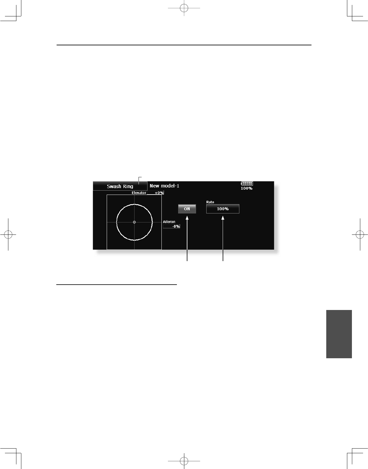
89
<Linkage Menu >
+(/,&237(5
$,53/$1(*/,'(5
ŏ5HWXUQWR/LQNDJH0HQX
ŏ7RXFKWKH>6ZDVK5LQJ@EXWWRQLQWKH/LQNDJH0HQX
WRFDOOWKHVHWXSVFUHHQVKRZQEHORZ
6ZDVK5LQJ /LPLWVWKHVZDVKWUDYHOZLWKLQDÀ[HGUDQJHWRSUHYHQWOLQNDJHGDPDJH
+HOLFRSWHURQO\
This function limits the travel of the swash plate to
prevent linkage damage as the aileron and elevator
operation is used. It is useful for 3D heli setting.
Swash ring setting procedure
3XVKWKH6ZDVKULQJEXWWRQRQWKHOLQNDJH
PHQX
3XVK$&7,1+EXWWRQWRDFWLYDWH
7KHPRYHPHQWDUHDPRQLWRUVKRZVWKHFXUUHQW
DLOHURQDQGHOHYDWRUYDOXHVDQGOLPLWUDQJHVE\WKH
\HOORZFLUFOH
$GMXVWWKHUDWHWRWKHPD[LPXPDPRXQWRI
VZDVKSODWHGHFOLQH
7KHVZDVKPRYHPHQWLVOLPLWHGZLWKLQWKHFLUFOH
$GMXVWPHQWUDQJH
5DWHEXWWRQ$FWLYDWHEXWWRQ
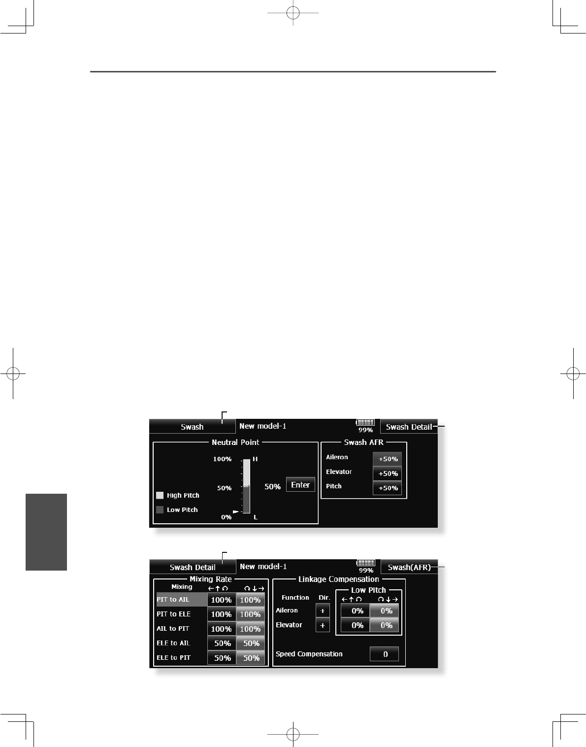
90 <Linkage Menu >
+(/,&237(5
$,53/$1( */,'(5
ŏ5HWXUQWR/LQNDJH0HQX
ŏ7R6ZDVK
$)5VFUHHQ
ŏ5HWXUQWR/LQNDJH0HQX
ŏ7RXFKWKH>6ZDVK@EXWWRQLQWKH/LQNDJH0HQXWR
FDOOWKHVHWXSVFUHHQVKRZQEHORZ
6ZDVK 6ZDVKRSHUDWLRQOLQNDJHFRUUHFWLRQIXQFWLRQ
7KLVVZDVKVHWXSVFUHHQGRHVQRWDSSHDUIRUVZDVKW\SH+
Neutral Point
On your linkages, if the servo horn deviates from
perpendicular at neutral, the linkage compensation
functions may not work effectively. This neutral
point setting reads the linkage compensation neutral
position. However, this adjustment only changes the
reference point of the compensation function on the
swash details screen and does not affect the neutral
position of other functions.
*Before using the compensation function, set the neutral point.
Swash AFR
The swash AFR function adjusts (increases/
decreases/reverse) the rate (travel) of the aileron,
elevator, and pitch functions.
Mixing Rate
(Normally, the default value is used.)
7KLVPL[LQJUDWHLVXVHGIRUPLQRUFRUUHFWLRQWRWKH
swash plate so that it moves in the correct direction
for aileron, elevator, and pitch operation.
&RPSHQVDWLRQPL[LQJLVVKRZQEHORZ
*PIT →AIL/PIT →ELE/AIL →PIT/ELE →AIL/ELE →PIT
8VHWKHFRUUHVSRQGLQJFRPSHQVDWLRQPL[LQJDQGDGMXVWVR
that the swash plate moves in the correct direction.
Linkage Compensation
7KLVFRPSHQVDWLRQPL[LQJLVXVHGWRDGMXVWIRU
interference when the ailerons or elevators are
operated when the throttle stick was in the low or
high position.
Speed Compensation
This speed compensation function make adjustments
for interference when the travel of each servo is
different due to swash plate operation. For HR-3, it
compensates the speed by dropping the operating
speed of the aileron and pitch servos during elevator
operation.
ŏ7R6ZDVK
'HWDLOV
VFUHHQ

91
<Linkage Menu >
+(/,&237(5
$,53/$1(*/,'(5
Neutral point setting procedure
%HFRPHVWKHFRPSHQVDWLRQUHIHUHQFHSRLQW
$GMXVWLQJWKHVHUYRKRUQVRWKDWWKHQHXWUDOSRLQW
SRVLWLRQLVQHDUWKH SRVLWLRQPDNHVWKHPL[LQJ
DPRXQWVPDOO
+ROGWKHVHUYRKRUQDWDULJKWDQJOHWRWKH
OLQNDJHURGDQGWKHQWRXFKWKH>(QWHU@EXWWRQ
DQGUHDGWKHDFWXDOQHXWUDOSRLQW
7KHQHXWUDOSRLQWLVGLVSOD\HGRQWKHVFUHHQ
$IWHUUHDGLQJWKLVQHXWUDOSRLQWXVHRWKHU
FRPSHQVDWLRQIXQFWLRQVWRPDNHIXUWKHU
DGMXVWPHQWV
7RH[LWWKHVHWWLQJWRXFKWKH>6ZDVK@EXWWRQ
Swash AFR setting procedure
$GMXVWVRWKDWWKHVSHFLÀHGRSHUDWLRQDPRXQW
LVREWDLQHGE\DLOHURQHOHYDWRUDQGSLWFK
RSHUDWLRQ
7RXFKWKHEXWWRQRIWKH$)5UDWHWREH
DGMXVWHG$GMXVWPHQWEXWWRQVDSSHDURQWKH
VFUHHQ
8VHWKHDGMXVWPHQWEXWWRQVWRDGMXVWWKH$)5
UDWH
,QLWLDOYDOXH
$GMXVWPHQWUDQJHa
RUWKHGLUHFWLRQRIRSHUDWLRQFKDQJHV
7RH[LWVHWWLQJWRXFKWKH>6ZDVK@EXWWRQ
Mixing rate setting procedure
+5LVGHVFULEHGDVDQH[DPSOH7KHPL[LQJ
DSSOLHGLQRWKHUVZDVKPRGHVLVGLIIHUHQWEXW
WKHVHWWLQJSURFHGXUHLVWKHVDPH
6HWWKHWKURWWOHVWLFNWRWKHVHWQHXWUDOSRLQW
$GMXVWWKHOHQJWKRIWKHOLQNDJHURGVRWKDWWKH
VZDVKSODWHLVKRUL]RQWDODWWKLVSRVLWLRQ
$OLWWOHDGMXVWPHQWXVLQJVXEWULPVKRXOGEH2.
$GMXVWVRWKDWSLWFKRSHUDWLRQZKHQWKHSLWFK
FXUYHLVVWUDLJKWLVPD[LPXP
$GMXVWWKH$,/ →3,7DPRXQWVRWKHUHLVQR
LQWHUIHUHQFHLQWKHHOHYDWRURUSLWFKGLUHFWLRQ
ZKHQWKHDLOHURQVWLFNLVPRYHGWRWKHOHIWDQG
ULJKW
$GMXVWWKHOHIWDQGULJKWVLGHVVHSDUDWHO\
$GMXVWWKH(/( →$,/DQG(/( →3,7DPRXQWVVR
WKHUHLVQRWLQWHUIHUHQFHLQWKHDLOHURQRUSLWFK
GLUHFWLRQZKHQWKHHOHYDWRUVWLFNLVPRYHGXS
DQGGRZQ
$GMXVWWKHXSDQGGRZQVLGHVVHSDUDWHO\
$GMXVWWKH3,7 →$,/DQG3,7 →(/(DPRXQWV
VRWKDWWKHVZDVKSODWHLVKRUL]RQWDOZKHQWKH
WKURWWOHVWLFNLVVHWWRPD[LPXPVORZDQGIXOO
KLJK
$GMXVWWKHVORZDQGKLJKVLGHVVHSDUDWHO\
7RH[LWVHWWLQJWRXFKWKH>6ZDVK'HWDLOV@
EXWWRQ
Linkage correction setting procedure
6HWWKHOLQNDJHFRPSHQVDWLRQDIWHUVHWWLQJWKH
PL[LQJUDWH
7KLVIXQFWLRQFRPSHQVDWHVIRUHOHYDWRU
LQWHUIHUHQFHE\DLOHURQRSHUDWLRQRUDLOHURQ
LQWHUIHUHQFHE\HOHYDWRURSHUDWLRQDW/RZ
SLWFKDQG+LSLWFKDWFROOHFWLYHSLWFK+5
HWFFRQWURO
6HWWKHWKURWWOHVWLFNWRWKHPD[LPXPVORZ
SRVLWLRQ0RYHWKHDLOHURQVWLFNWRWKHOHIWDQG
ULJKWDQGDGMXVWWKHDLOHURQFRPSHQVDWLRQ
DPRXQWVRWKDWLQWHUIHUHQFHLQWKHHOHYDWRURU
SLWFKGLUHFWLRQDWWKDWWLPHLVPLQLPDO
7KHOHIWDQGULJKWVLGHVFDQEHDGMXVWHG
VHSDUDWHO\
,IWKHLQWHUIHUHQFHLQFUHDVHVZKHQWKH
FRPSHQVDWLRQDPRXQWLVLQFUHDVHGPDNHWKH
FRPSHQVDWLRQGLUHFWLRQ
$GMXVWWKHHOHYDWRUFRPSHQVDWLRQDPRXQW
VRWKDWWKHLQWHUIHUHQFHLQWKHDLOHURQRUSLWFK
GLUHFWLRQZKHQWKHHOHYDWRUVWLFNZDVPRYHG
XSDQGGRZQLVPLQLPDO
3HUIRUPDLOHURQDQGHOHYDWRUFRPSHQVDWLRQ
VLPLODUO\IRUWKHWKURWWOHVWLFNIXOOKLJKVLGH
7RH[LWVHWWLQJWRXFKWKH>6ZDVK'HWDLOV@
EXWWRQ
Speed compensation setting procedure
6HWWKHWKURWWOHVWLFNWRWKHQHXWUDOSRLQW
SRVLWLRQ0RYHWKHHOHYDWRUVWLFNTXLFNO\DQG
DGMXVWWKHVSHHGFRPSHQVDWLRQDPRXQWVR
WKDWWKHLQWHUIHUHQFHLQWKHSLWFKGLUHFWLRQLV
PLQLPDO
7RH[LWVHWWLQJWRXFKWKH>6ZDVK'HWDLOV@
EXWWRQ
Note:
,IWKHOLQNDJHLVWRRORQJRUVKRUWFRUUHFW
FRPSHQVDWLRQZLOOQRWEHDSSOLHG&RUUHFWWKLV
EHIRUHFRQWLQXLQJ7KHSLWFKDQJOHFKDQJHV
DIWHUDQ\DGMXVWPHQW5HVHWWKHSLWFKDQJOH
ZKHQDFWXDOO\IO\LQJDIWHUFRPSHQVDWLRQ
SURFHVVLQJ
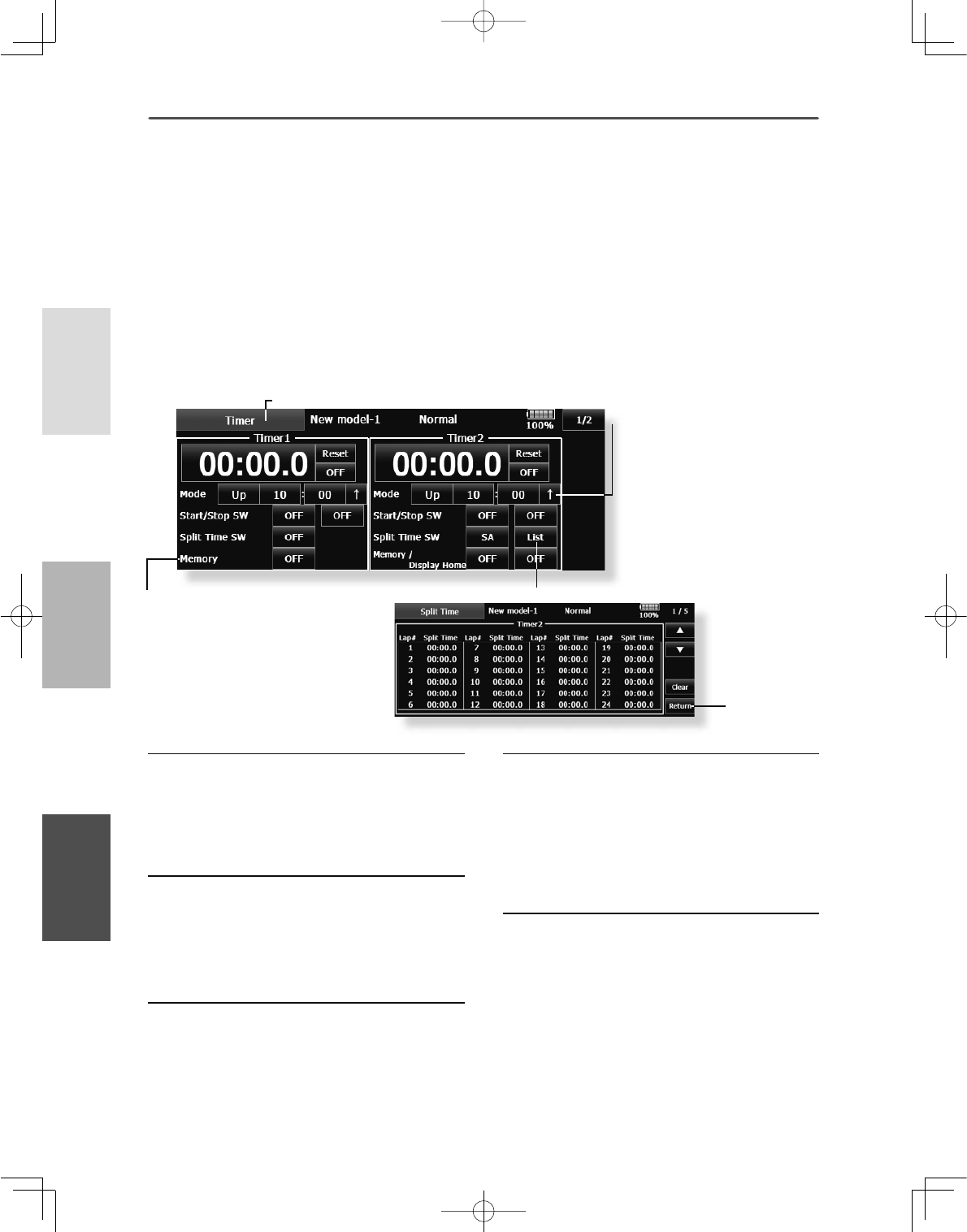
92 <Linkage Menu >
+(/,&237(5
$,53/$1( */,'(5
ŏ0HPRU\LVWXUQHG21WKHSRZHU
2))DQGDPRGHOFKDQJHZLOOQRW
EHUHVHWWLPHUHLWKHU
ŏ>Ń@$QDODUPVRXQGVHYHU\
PLQXWHRIWKHHODSVHG WLPH
IURPWLPHUVWDUW&RQYHQWLRQDO
PRGH
>Ņ@$QDODUPVRXQGVHYHU\
PLQXWHRIWKHUHPDLQLQJWLPH
XSWRWKHDODUPWLPH
ŏ 7RXFKWKH>7LPHU@EXWWRQLQWKH/LQNDJH0HQXWR
FDOOWKHVHWXSVFUHHQVKRZQEHORZ
7LPHU 7LPHUVHWWLQJDQGODSWLPHGLVSOD\
The Timer function may be set for any desired time,
LHHQJLQHUXQWLPHVSHFL¿HGWLPHVIRUFRPSHWLWLRQV
etc. Two independent timers are provided for your
use. The timers are stored independently with each
model, meaning that when you switch between
model setups, the timer associated with the new
model is brought up automatically.
The timers may be set to start and stop from the
motion of any switch or stick. You may set the ON
and OFF directions freely. Each timer has a capacity
RIXSWRPLQXWHVVHFRQGV
Up timer/Down timer/Hour selection
7RXFKWKHPRGHEXWWRQDQGVHOHFWWKHW\SHRI
WLPHU
7LPHUWLPHVHWWLQJ
7RXFKWKH0RGHPLQXWHVRUVHFRQGVEXWWRQ
$GMXVWPHQWEXWWRQVDSSHDURQWKHVFUHHQ
8VHWKHVHEXWWRQVWRVHWWKHWLPHUWLPH
Start/SWtop switch setting
7RXFKWKH6WDUW6WRS6: 18//EXWWRQWRFDOO
WKH6ZLWFK!VFUHHQDQGWKHQVHOHFWWKH
VZLWFKDQGLWV21GLUHFWLRQ
)RUDGHWDLOHGGHVFULSWLRQRIWKHVHOHFWLRQ
PHWKRGVHH>6ZLWFK6HWWLQJ0HWKRG@DWWKH
EDFNRIWKLVPDQXDO7KHWLPHUVZLWFKHVFDQ
EHVHWIRUHDFKFRQGLWLRQ
Lap time switch selection
7RXFKWKH/DS6:18//EXWWRQWRFDOOWKH
3URJ0L[VFUHHQDQGWKHQVHOHFWWKHVZLWFK
DQGLWV21GLUHFWLRQ
)RUDGHWDLOHGGHVFULSWLRQRIWKHVZLWFK
VHWWLQJPHWKRGVHH>6ZLWFK6HWWLQJ0HWKRG@
DWWKHEDFNRIWKLVPDQXDO7KHWLPHUVZLWFKHV
FDQEHVHWIRUHDFKFRQGLWLRQ
Each timer may be set for count-down or count up
operation with your choice of a target time. Also
split time may be set up and counted.
If a target time is set and the timer reaches this point,
DEX]]HUZLOOVRXQGIRUHDFKFRXQWJHQHUDWHG
Countdown timers sound one short beep during the
last twenty seconds and two short beeps during the
last ten seconds before reaching the target, then a
long tone at the target time, and continue counting
with displaying a minus (-) sign. Count-up timers
also beep the last twenty and ten seconds, beep the
target time, and keep counting upwards until shut
down.
Timer operation
ŏ7LPHUDQG7LPHUDUHVWDUWHGDQGVWRSSHG
E\\RXUFKRLFHRIVZLWFK
ŏ7RFRXQWWKHODSWLPHVHOHFWWKHODSWLPH
VZLWFK(DFKWLPHWKLVVZLWFKLVRSHUDWHGWKH
ODSWLPHLVVWRUHG7RGLVSOD\WKHODSWLPH
WRXFKWKHUHVSHFWLYH>/LVW@EXWWRQ
ŏ7RUHVHWDWLPHUWRXFKWKHUHVSHFWLYH>5HVHW@
EXWWRQ7RH[LWWKHVHWWLQJ WRXFKWKH>7LPHU@
EXWWRQ
Hour mode
$Q+285PRGHZKLFKFRXQWVXSWRKRXUV
PLQXWHVKDVEHHQDGGHGWRWKHWLPHUPRGHV
ŏ7KLVPRGHLVFRQYHQLHQWZKHQXVHGDWHQJLQH
PDLQWHQDQFHSHULRGDQGRWKHUORQJWHUP
PHDVXUHPHQWV
ŏ:KHQWKH+285PRGHLVVHW´[[KRXU
[[PLQXWHµLVGLVSOD\HGRQWKHFRXQWWLPH
GLVSOD\6HFRQGVDUHQRWGLVSOD\HG
ŏ:KHQWKH+285PRGHLVVHW´µEOLQNVHDFK
VHFRQGGXULQJWLPHURSHUDWLRQ
ŏ:KHQWKH+285PRGHLVVHWWKHDODUP
IXQFWLRQODSWLPHPHDVXUHPHQWIXQFWLRQDUH
LQKLELWHG
ŏ5HWXUQWR7LPHU
VFUHHQ
<Lap time list>
ŏ5HWXUQWR/LQNDJH0HQX
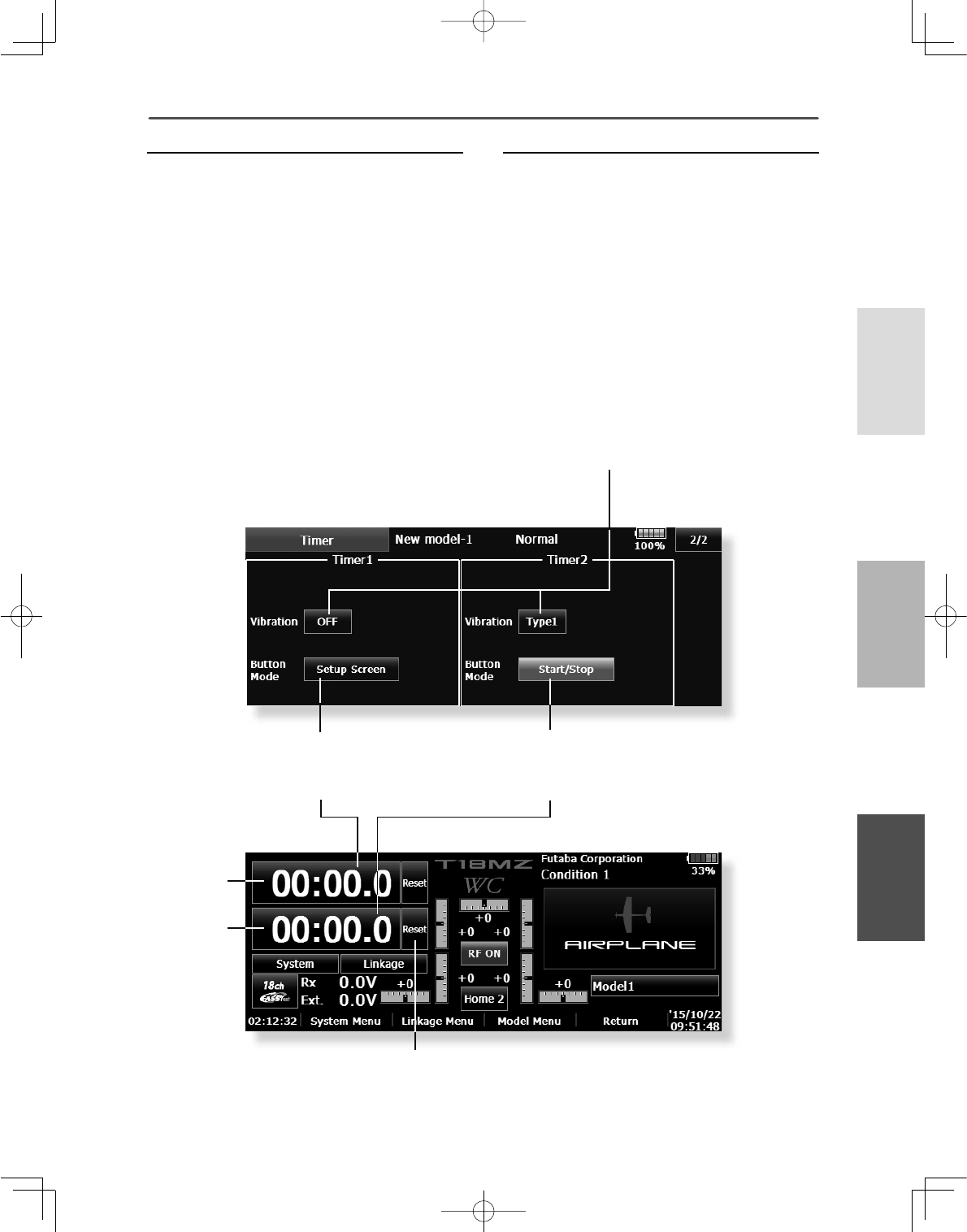
93
<Linkage Menu >
+(/,&237(5
$,53/$1(*/,'(5
Vibration
If a set period comes, you will be alerted by
vibration.
>@LVSXVKHGRQDWLPHUVFUHHQDQG
VFUHHQLVRSHQHG
9LEUDWLRQ>2))@LVSXVKHGDQGLWLVPDGH
>7\SH@7KHNLQGRIYLEUDWLRQ LVFKRVHQIURP
7\SHWR7\SH7KHLQWHUYDORIYLEUDWLRQ
FKDQJHV,WFDQVHWXSVHSDUDWHO\E\WKH
7LPHUDQGWKH7LPHU
Button Mode
A setup of operation when the timer button in a
home screen is pushed.
>@LVSXVKHGRQDWLPHUVFUHHQDQG
VFUHHQLVRSHQHG
%XWWRQPRGHLVFKRVHQIURPWZR
>6HWXS6FUHHQ@
,IWKHWLPHURIDKRPHLVSXVKHGLWZLOOMXPSWR
DWLPHUVHWXSVFUHHQ
>6WDUW6WRS@
,IWKHWLPHURIDKRPHLVSXVKHG$WLPHU
SHUIRUPVDVWDUWVWRSGLUHFWO\ZLWKDKRPH
VFUHHQ
ŏ 7RXFKWKH>7LPHU@EXWWRQLQWKH/LQNDJH0HQX
DQGWKH>@EXWWRQSXVKHGFDOOWKHVHWXS
VFUHHQVKRZQEHORZ
ŏ+RPHVFUHHQ
ŏ7LPHU
ŏ7LPHU
ŏ >2))@ →>7\SH@ ,ILWFDUULHV
RXWOLNHWKLVDYLEUDWLRQIXQFWLRQ
ZLOOZRUN
ŏ >6HWXS6FUHHQ@
,IWKHWLPHURIDKRPHLV
SXVKHGLWZLOOMXPSWRD
WLPHUVHWXSVFUHHQ
ŏ $WLPHLVUHVHW
ŏ >6WDUW6WRS@
,IWKHWLPHURIDKRPHLVSXVKHG
$WLPHUSHUIRUPVDVWDUWVWRS
GLUHFWO\ZLWKDKRPHVFUHHQ