Futaba T18SZ-24G Radio Control User Manual Part I
Futaba Corporation Radio Control Part I
UserManual.wiki
>
Futaba
>
T18SZ-24G User Manual
>
User Manual-Part I
Contents
1.
User Manual-Part I
2.
User Manual-Part II
3.
User Manual-Part III
User Manual-Part I
Navigation menu
Upload a User Manual
Namespaces
Wiki Guide
HTML
PDF
Info
Views
User Manual
Discussion / Help
Navigation

![TABLE OF CONTENTSTimer ............................................................... 84T1-T6 Setting .................................................. 86Multiprop ........................................................ 87Function Name ............................................... 88Telemetry......................................................... 89Telemetry:receiver [battery] ......................... 90Telemetry:receiver [ext-batt] ......................... 91Telemetry:temperature .................................. 92Telemetry:rpm sensor .................................... 93Telemetry:altitude .......................................... 94Telemetry:altitude [variometer] .................... 95Telemetry:voltage [battery] ........................... 96Telemetry:voltage [ext-batt] .......................... 97Telemetry:GPS [distance] .............................. 98Telemetry:GPS [speed] ................................ 100Telemetry:GPS [altitude,variometer,position] ... 101Sensor ............................................................ 102Sensor:reload ................................................ 103Sensor:register .............................................. 103Sensor:change slot ........................................ 104Tele. Setting ................................................... 105Warning ......................................................... 106Trainer ........................................................... 107Data Reset ..................................................... 110Cond. Hold .....................................................111FUNCTIONS OF MODEL MENU ............... 112●Common Functions ...................................... 112Condition Select ........................................... 113AFR .............................................................. 115Dual Rate ...................................................... 116Program Mix ................................................. 117●Airplane/Glider Functions ........................... 121Model Menu functions list ........................... 121AIL Differential ............................................ 123Flap Setting ................................................... 124AIL to Camber FLP ..................................... 125AIL to Brake FLP ......................................... 126AIL to RUD ................................................... 127Airbrake to ELE ........................................... 128RUD to AIL ................................................... 130Camber Mix .................................................. 131ELE to Camber ............................................ 133Camber FLP to ELE .................................... 134Buttery ........................................................ 135Trim Mix 1/2 ................................................. 137Airbrake (Airplane only) ............................. 139Gyro (for GYA type gyro) ............................ 141V-tail .............................................................. 143Ailevator ........................................................ 144Winglet .......................................................... 145Motor ............................................................. 146Acceleration .................................................. 147RUD to ELE .................................................. 148Snap Roll (Airplane only) ............................ 149●Helicopter Functions .................................... 150Model Menu functions list ........................... 150PIT Curve/Pit trim ....................................... 151THR Curve/Throttle hover trim ................. 154Acceleration .................................................. 157Throttle Hold ................................................ 158Swash Mix ..................................................... 159Throttle Mix .................................................. 160PIT to Needle ................................................ 161PIT to RUD (Revolution mix) ..................... 162Gyro (for GY type gyro) .............................. 163Governor ....................................................... 164●Common Operations used in function setup screen ............................................................. 166●Updating ........................................................ 174●FX-30 / T12FG → T18SZ Model Data Conversion .................................................... 175](https://usermanual.wiki/Futaba/T18SZ-24G.User-Manual-Part-I/User-Guide-2758307-Page-3.png)

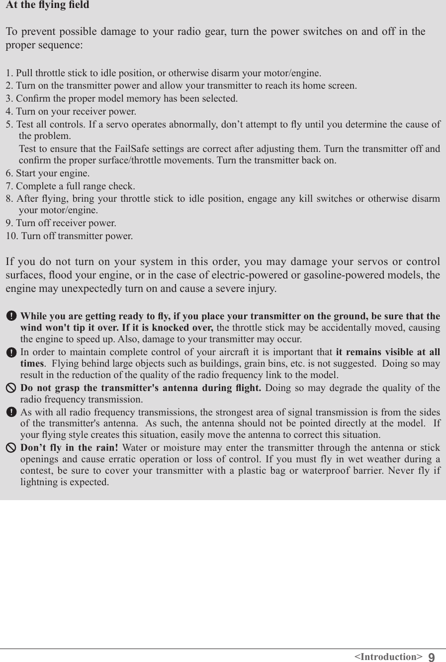
![12 <Before Use>• FT2F2100BV2 transmitter battery pack - the (2,100mAh) transmitter LiFe battery pack may be easily exchanged with a fresh one to provide enough capacity for extended ying sessions.• Trainer cord - the optional training cord may be used to help a beginning pilot learn to fly easily by placing the instructor on a separate transmitter. Note that the T18SZ transmitter may be connected to another T18SZ system, as well as to any other models of Futaba transmitters. The T18SZ transmitter uses one of the three cord plug types according to the transmitter connected. (Refer to the description at the TRAINER function instructions). The part number of this cord is: FUTM4405.• Servos - there are various kinds of servos. Please choose from the servos of Futaba what suited the model and the purpose of using you. If you utilize a S.BUS system, you should choose a S.BUS servo. An analog servo cannot be used if "FASSTest12CH mode" is used.• Telemetry sensor - please purchase an optional sensor, in order to utilize bidirectional communication system and to acquire the information from a model high up in the sky. [Temperature sensor : SBS-01T/TE] [Altitude sensor : SBS-01A] [RPM sensor magnet type : SBS-01RM][RPM sensor optical type : SBS-01RO] [RPM sensor brushless motor type : SBS-01RB] [GPS sensor : SBS-01G] [Voltage sensor : SBS-01V]• Neckstrap - a neckstrap may be connected to your T18SZ system to make it easier to handle and improve your ying precision since your hands won’t need to support the transmitter’s weight.• Y-harnesses, servo extensions, hub,etc - Genuine Futaba extensions and Y-harnesses, including a heavy-duty version with heavier wire, are available to aid in your larger model and other installations.• Gyros - a variety of genuine Futaba gyros is available for your aircraft or helicopter needs. • Governor - for helicopter use. Automatically adjusts throttle servo position to maintain a constant head speed regardless of blade pitch, load, weather, etc.• Receivers - various models of Futaba receivers may be purchased for use in other models. (Receivers for FASSTest and FASST, T-FHSS, S-FHSS types are available.)The following additional accessories are available from your dealer. Refer to a Futaba catalog for more information:](https://usermanual.wiki/Futaba/T18SZ-24G.User-Manual-Part-I/User-Guide-2758307-Page-12.png)
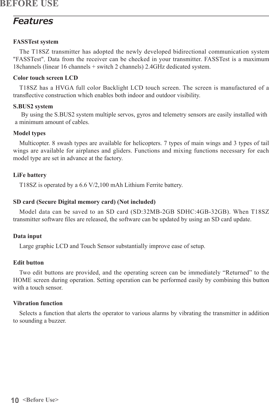
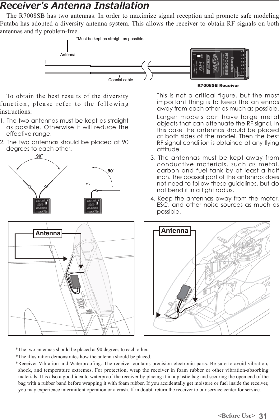
![29<Before Use>Link/Mode SwitchUse the small plastic screw driver that was included with your receiver. The Link/Mode Switch is also used for the CH mode selection. Extra Voltage ConnectorUse this connector when using a voltage telemetry device to send the battery voltage (DC0 ~ 70V) from the receiver to the transmitter. You will need to purchase the optional External Voltage input cable (CA-RVIN-700) FUTM5551.You can then make a cable with an extra connector to the External voltage connector.Before using the receiver, be sure to read the precautions listed in the following pages.Receiver R7008SBConnector"1 through 6": outputs for the channels 1 through 6"7/B": outputs of 7 channels and power. "8/SB": outputs of 8 channels or S.BUS port.[S.BUS Servo S.BUS Gyro ]*When using 8/SB as S.BUS, you have to set CH MODE of the following page to mode B or mode D."S.BUS2": outputs of S.BUS2 port.[S.BUS2 Servo S.BUS2 Gyro Telemetry Sensor ]*When using 9 or more channels, use an S.BUS function or use a second R7008SB and link both to your transmitter.Connector insertion Firmly insert the connector in the direction shown in the gure. Insert the S.BUS2 by turning it 90 degrees.+-Do not connect either a switch or battery in this manner.ReceiverDanger DangerDon't connect a connector, as shown in a before gure.*It will short-circuit, if it connected in this way. A short circuit across the battery terminals may cause abnormal heating, re and burns.WarningS.BUS2 connectorsDon't connect an S.BUS servo / gyro to S.BUS2 connector.LED Monitor This monitor is used to check the CH mode of the receiver.Receiver nomenclature](https://usermanual.wiki/Futaba/T18SZ-24G.User-Manual-Part-I/User-Guide-2758307-Page-29.png)
![30 <Before Use>R7008SB CH ModeThe R7008SB receiver is a very versatile unit. It has 8 PWM outputs, S.BUS and S.BUS2 outputs. Additionally the PWM outputs can be changed from channels 1-8 to channels 9-14. If you only desire to use it as an 8 channel receiver (without S.BUS), it can be used without any setting changes.The T18SZ has the ability to link to two R7008SB receivers. One of them outputting channels 1-8 and the other outputting channels 9-14 giving you 14 PWM channels. Instructions for this configuration and S.BUS operation follow.[How to change the R7008SB Channel mode.]1. Press and hold down the Link/Mode button on the R7008SB receiver.2. Turn the receiver on while holding down the Link/Mode button. when the LED begins to blink green/red the button may be released.3. The LED should now be blinking red in one of the patterns described by the chart below.4. Each press of the Mode/Link button advances the receiver to the next mode.5. When you reach the mode that you wish to operate in, press and hold the Mode/Link button for more than 2 seconds.6. Once locked into the correct mode the LED will change to a solid color.7. Please cycle the receiver(s) power off and back on again after changing the Channel Mode.Receiver connectorSetting channelMode A1 ~ 8CHMode B1 ~ 7CHMode C9 ~ 14CHMode D9 ~ 14CH1 11992 2 2 10 103 3 3 11 114 4 4 12 125 5 5 13 136 6 6 14 147/B 7 7 - -8/SB 8 S.BUS - S.BUSRed LED blink 1time 2time 3time 4timeR7008SB CH MODE TABLEDangerDon't touch wiring. * There is a danger of receiving an electric shock.Do not short-circuit the battery terminals.* A short circuit across the battery terminals may cause abnormal heating, re and burns.Please double check your polarity ( +and -) when hooking up your connectors. * If + and - of wiring are mistaken, it will damage, ignite and explode.Don’t connection to Extra Voltage before turning on a receiver power supply.](https://usermanual.wiki/Futaba/T18SZ-24G.User-Manual-Part-I/User-Guide-2758307-Page-30.png)
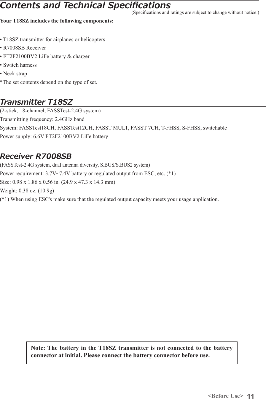
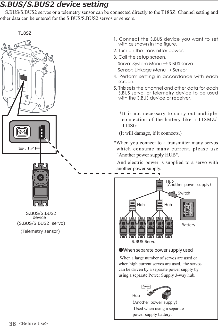
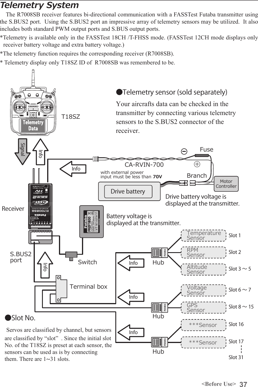
![35<Before Use>S.BUS2 System When using the S.BUS2 port, an impressive array of telemetry sensors may be utilized. Receiver port S.BUS ServoS.BUS GyroS.BUS2 ServoS.BUS2 Gyro Telemetry sensorS.BUS ○ ○ ×S.BUS2 × (※) ○ ○S.BUS2 TABLE(※)Don't connect S.BUS Servo, S.BUS Gyro to S.BUS2 connector. S.BUS2PortS.BUSPort(8/SB)HubHub Hub HubRudder ServoS.BUS2 ServoS.BUS ServoS.BUS2 servoConnection is possibleS.BUS2 gyroConnection is possibleS.BUS servoConnection is impossibleTelemetry sensorConnection is impossibleS.BUS2GYROCH Mode is set to ModeB [D]. +Telemetry SensorS.BUS servos and gyros and S.BUS2 servos and gyros must be used in the correct receiver ports. Please refer to the instruction manual to make sure you connect to the correct one.](https://usermanual.wiki/Futaba/T18SZ-24G.User-Manual-Part-I/User-Guide-2758307-Page-35.png)
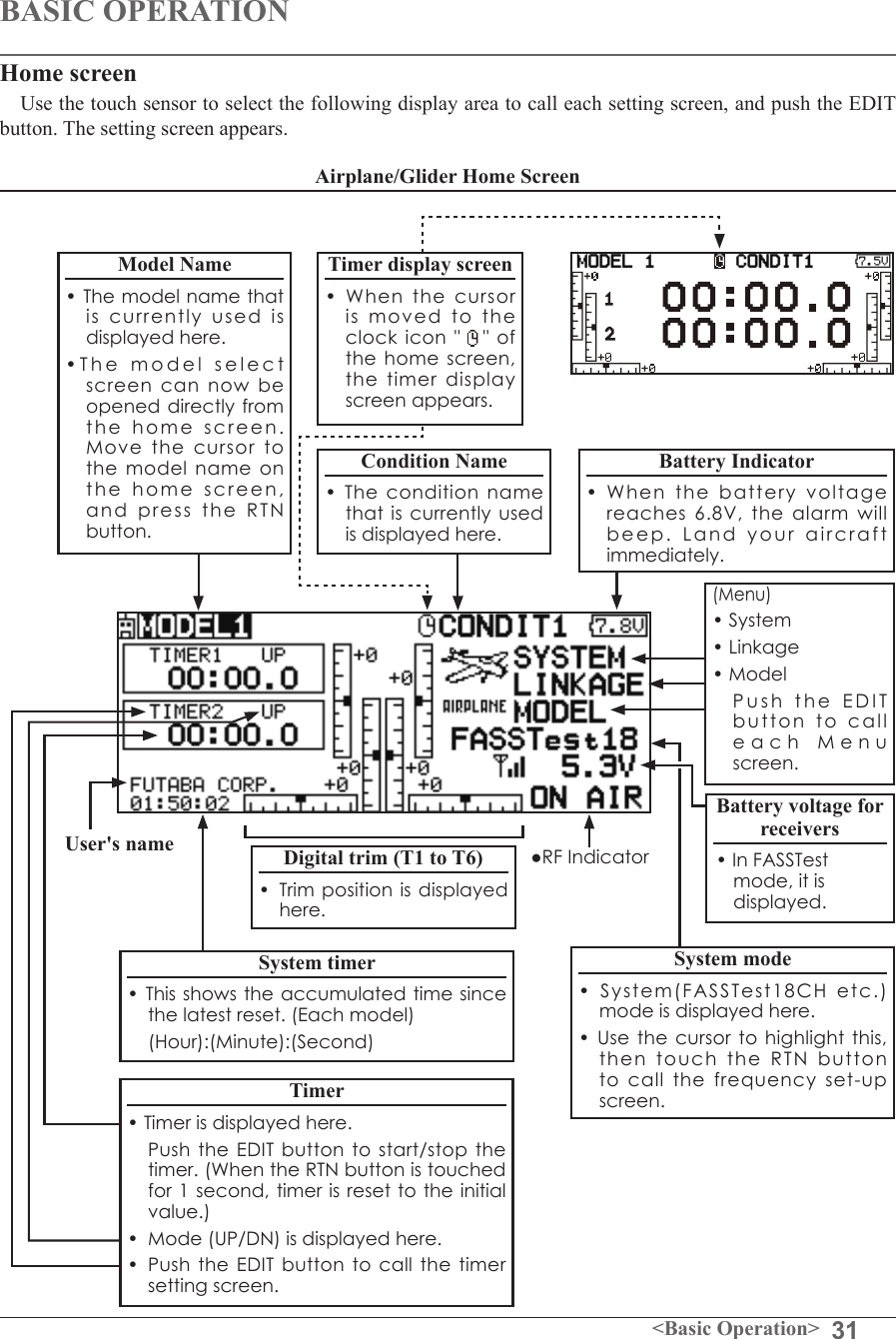
![32 <Basic Operation>Throttle/Pitch Position Display• Throttle and pitch position is displayed here. Push the EDIT button to call the throttle curve or pitch curve setting screen directly.Helicopter Home ScreenTo activate/deactivate Condition Hold:1.Move the cursor to [CND HOLD].2.Set the throttle stick lower than the 1/3 point and push the EDIT button to activate/deactivate the condition hold function.*For a detailed description, refer to [COND.HOLD] function instructions.*Condition hold operation is displayed. ("IS ON")WARNINGBe sure to conrm the model name before ying your aircraft.Check the battery voltage as often as possible and try to charge the battery earlier. If the battery alarm makes a sound, land your aircraft immediately.*You can adjust the LCD contrast by the display setting in the system menu.](https://usermanual.wiki/Futaba/T18SZ-24G.User-Manual-Part-I/User-Guide-2758307-Page-39.png)
![33<Basic Operation>Screen lockTo prevent the data from being changed by erroneous touching of the touch sensor during flight, a function which makes an touch sensor impossible temporarily. How to lock1. The home screen is displayed.2. Press the S1 button for about 1 second. "LOCK" is displayed and the touch sensor is disabled.How to unlock1. Press the S1 button for about 1 second in the touch sensor locked state. The touch sensor is enabled again.STARTUP LOCKAuto Lock functions automatically when the model changes or power is turned on.*To temporarily allow access to the T18SZ programming press and hold the S1 bitton for one second. Please note, the Auto Lock function timer will resume immediately once again.AUTOMATIC LOCK Auto Lock functions automatically when there is no operation from the HOME screen display for a chosen number of seconds.*Two kinds of automatic locks can be chosen by [DISPLAY] of [SYSTEM MENU].](https://usermanual.wiki/Futaba/T18SZ-24G.User-Manual-Part-I/User-Guide-2758307-Page-40.png)
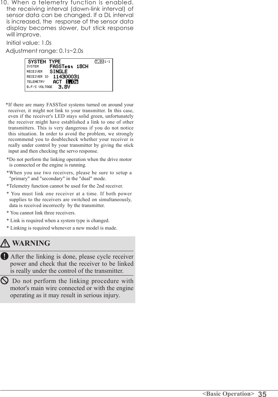
![34 <Basic Operation> Link procedure (T18SZ/R7008SB)Each transmitter has an individually assigned, unique ID code. In order to start operation, the receiver must be linked with the ID code of the transmitter with which it is being paired. Once the link is made, the ID code is stored in the receiver and no further linking is necessary unless the receiver is to be used with another transmitter. When you purchase additional R7008SB receivers, this procedure is necessary; otherwise the receiver will not work. Link procedure1. Place the transmitter and the receiver close to each other within half (0.5m) meter. 2. Turn on the transmitter. 3. Select [SYSTEM TYPE] at the Linkage menu and access the setup screen shown below by touching the RTN button.4. When you use two receivers on one model, you must change from [SINGLE] to [DUAL]. *Only two receivers can be used. In "DUAL", two setting items come out. Input, respectively.5. When changing battery fail-safe voltage from the initial value 3.8V, voltage is changed here. * Only in FASSTest Mode.6.[RECEIVER-ID] is chosen by scrolling and the RTN button is pushed. The transmitter will emit a chime as it starts the linking process.7. When the transmitter starts to chime, power on the receiver. The receiver should link to the transmitter within about 1 second. 8. If linking fails, an error message is displayed. Bring the transmitter closer to the receiver and repeat the procedure above from Step 2.9. ACT will be chosen if telemetry is used. It is INH when not using it. Less than 0.5 mIn "Link" ModeReceiver ON:You can do this through the LINKAGE Menu and scroll to System and press RTN.ID of a primary receiver displays.In DUAL, a primary receiver is link previously. Next, a secondary receiver is link.ID of a secondary receiver displays.](https://usermanual.wiki/Futaba/T18SZ-24G.User-Manual-Part-I/User-Guide-2758307-Page-41.png)
![39<Functions of System Menu>SYSTEM MENUSystem Menu functions table[DISPLAY]: LCD contrast and back light adjustment.[SYSTEM TIMER]: Resets the accumulated timer for each model.[USER NAME]: User name registration.[SOUND]: Various volume control and low battery setting.[H/W SETTING]: H/W reverse, stick mode, stick calibration, and switch position.[INFORMATION]: Displays the program version, SD card information, and language selection.[RANGE CHECK]: A transmitting output is lowered and the check before a ight is carried out.[S.BUS SERVO]: S.BUS servo setting.The System Menu sets up functions of the transmitter: This does not set up any model data.● Select [SYSTEM] at the home screen and call the system menu shown below by touching the RTN button.● Scrolling the touch sensor to select the function you want to set and call the setup screen by touching the RTN button.● Select the function name and return to the System menu by touching the RTN button or pushing the Home/Exit button.<SensorTouch™>●Access setup screenScrolling● Moving cursor](https://usermanual.wiki/Futaba/T18SZ-24G.User-Manual-Part-I/User-Guide-2758307-Page-44.png)
![40 <Functions of System Menu>● Select the function name and return to the System menu by touching the RTN button or pushing the Home/Exit button.<SensorTouch™>LCD contrast adjustment1. Scrolling the touch sensor to select "LCD CONTRAST" and touch the RTN button to switch to the data input mode and adjust the contrast by turning the touch sensor to the left and right. Setting range: (Lighter) 0 to 30 (Darker) Initial value: 15 Touch the RTN button to end adjustment and return to the cursol move mode.*Adjust to the contrast while watching the screen display.*When you want to reset the contrast to the initial state, select "LCD CONTRAST" and touch the RTN button for 1 second.Backlight brightness adjustment1. Scrolling the touch sensor to select "BACKLIGHT BRIGHTNESS" and touch the RTN button to switch to the data input mode and adjust the contrast by turning the touch sensor to the left and right. Setting range: (Darker) 0 to 30 (Lighter) Initial value: 10 Touch the RTN button to end adjustment and return to the cursol move mode.*Adjust to the brightness while watching the screen display.*When you want to reset the contrast to the initial state, select "BACKLIGHT BRIGHTNESS" and touch the RTN button for 1 second.Back-light off-timer1. Select "Back-light timer" and touch the RTN button to switch to the data input mode and adjust the back-light off-timer by scrolling the touch sensor. "OFF TIMER": Adjust the time when the back-DISPLAY LCD contrast adjustment and automatic key lockThe following LCD screen adjustments and auto power off setting are possible:● Backlighting brightness adjustment● Backlighting off timer adjustment● Automatic key lock setuplight turns off after operating the touch sensor. Setting range: 10 to 240 sec (each 10 sec), OFF (always on) Initial value: 10 sec*When you want to reset the value to the initial state, touch the RTN button for one second.2. Touch the RTN button to end adjustment and return to the cursor mode.*If the back light is on for a long time, consumption current will increase. Start lockAuto Lock functions automatically when the model changes or power is turned on.*To temporarily allow access to the T18SZ programming press and hold the S1 button for one second. Please note, the Auto Lock function timer will resume immediately once again.1. Select "STARTUP LOCK" and touch the RTN button to switch to the data input mode and adjust the ON or OFF by scrolling the touch sensor. Setting range: ON or OFF Initial value: OFFAutomatic lockAuto Lock functions automatically when there is no operation from the HOME screen display for a chosen number of seconds.1. Scrolling the touch sensor to select "AUTOMATIC LOCK" and touch the RTN button to switch to the data input mode and adjust the time by turning the touch sensor to the left and right. Setting range: INH, 0 to 120 (s) Initial value: INH● Select [DISPLAY] at the system menu and call the setup screen shown below by touching the RTN button.Scrolling● Moving cursor● Selecting mode● Adjusting value](https://usermanual.wiki/Futaba/T18SZ-24G.User-Manual-Part-I/User-Guide-2758307-Page-45.png)
![41<Functions of System Menu>● Select the function name and return to the System menu by touching the RTN button or pushing the Home/Exit button.<SensorTouch™>Timer selection1.Move the cursor to the [MODE] item and touch the RTN button to switch to the data input mode. Select the mode by scrolling the touch sensor and touch the RTN button. TOTAL: Displays the total timer on the home screen. MODEL timer: Displays the model timer on the home screen. SYSTEM TIMER Resets the accumulated timer.This function resets the system timer displayed on the home screen.● T18SZ has two type system timers. TOTAL timer: Displays the total accumulated time on the transmitter from the last time the timer was reset. MODEL timer: Displays the total accumulated time on each model from the last time the timer was reset.● System timer displayed on the home screen can be selected.● Select [SYSTEM TIMER] at the system menu and call the setup screen shown below by touching the RTN button.Timer reset1.Move the cursor to the [SYSTEM TIMER] item and reset the timer to "00:00:00" by touching the RTN button for 1 second. After reset, the timer restarts from "00:00:00".Scrolling● Moving cursor● Selecting mode](https://usermanual.wiki/Futaba/T18SZ-24G.User-Manual-Part-I/User-Guide-2758307-Page-46.png)
![42 <Functions of System Menu>● Select the function name and return to the System menu by touching the RTN button or pushing the Home/Exit button.<SensorTouch™>USER NAME User name registrationThis function registers the T18SZ user name.*A name of up to 12 characters can be entered as the user name. (Space is also counted as 1 character.)User name registration1. Change the user name as described below: [Moving cursor in input box] Select [←] or [→], and touch the RTN button. [Deleting a character] When [DELETE] is selected and the RTN button is touched, the character immediately after the cursor is deleted. [Adding a character] When a candidate character is selected from the character list and the RTN button is touched, that character is added at the position immediately after the cursor.*A name of up to 12 characters long can be entered as the user name. (A space is also counted as 1 character.)2. At the end of input, select [ENTER] and touch the RTN button. (To terminate input and return to the original state, select [CANCEL] and touch the RTN button.)(Character list 1/3)(Character list 2/3)(Character list 3/3)● Select [USER NAME] at the system menu and call the setup screen shown below by touching the RTN button.● Push the S1 button to call next page. Current user nameInput boxCursor (blink)Scrolling● Moving cursor](https://usermanual.wiki/Futaba/T18SZ-24G.User-Manual-Part-I/User-Guide-2758307-Page-47.png)
![43<Functions of System Menu>● Select the function name and return to the System menu by touching the RTN button or pushing the Home/Exit button.<SensorTouch™>3 independent sound volumes: "WARNING", "VOICE" and others, are available."LOW BATTERY" adjusts low battery alarm voltage to match a battery.● Select [SOUND] at the system menu and access the setup screen shown below by touching the RTN button.● LOW BATTERY : 6.8V~7.6VSound volume operation1. Move the cursor to the [WARNING][VOICE] or [OTHER SOUND] item and touch the RTN button to switch to the data input mode.2. Select the volume by scrolling the touch sensor. *The display blinks.3.Touch the RTN button.Low battery voltage operation1. Move the cursor to the [LOW BATTERY] item and touch the RTN button to voltage to the data input mode.2. Select the voltage by scrolling the touch sensor. (6.8V-7.6V)*The display blinks.3.Touch the RTN button.SOUND Turns off the buzzer.Scrolling● Moving cursor● Adjusting value](https://usermanual.wiki/Futaba/T18SZ-24G.User-Manual-Part-I/User-Guide-2758307-Page-48.png)