Contents
- 1. User Manual-Part I
- 2. User Manual-Part II
- 3. User Manual-Part III
User Manual-Part I

1M23N00000

INTRODUCTION............................................... 4
●Support and Service ......................................... 4
●Application, Export, and Modication ........... 5
●Denitions of Symbols ...................................... 6
●Safety Precautions (do not operate without
reading) ............................................................. 6
BEFORE USE ................................................... 10
●Features of T18SZ ......................................... 10
●Contents and technical specications ........... 11
●Accessories ....................................................... 12
●Transmitter controls ....................................... 13
Cautions on handling antenna ...................... 14
LED monitor ................................................... 14
Switch (SA-SH) ............................................... 15
Digital trim (T1-T4) ....................................... 15
Volume (LD, RD) ............................................ 15
Home/Exit, U.menu/Mon. Button ................. 15
Touch sensor ................................................... 16
Stick adjustment ............................................. 17
SD card ............................................................ 18
How to remove a rear case ............................ 19
Connector/Plug ............................................... 20
Installation and removal of the battery ........ 21
●Receiver nomenclature ................................... 22
●Receiver's antenna installation ...................... 24
●Safety precautions when installing servos ... 25
●S.BUS/S.BUS2 Installation ............................ 26
●S.BUS Wiring example ................................... 27
●S.BUS2 System ................................................ 28
●S.BUS/S.BUS2 Devicesetting ......................... 29
●Telemetry System ............................................ 30
BASIC OPERATION ....................................... 31
●Battery Charging ............................................ 31
How to charge the NiMH Battery ................. 31
●How to turn ON/OFF the transmitter .......... 32
When turning on ............................................ 32
When turning off ............................................ 32
●Registration of the user's name ..................... 32
●Home screen .................................................... 33
●Screen lock....................................................... 35
●Link procedure .............................................. 36
●Range testing your R/C system...................... 38
FUNCTIONS OF SYSTEM MENU ................ 39
Display ............................................................. 40
System Timer .................................................. 41
User Name ....................................................... 42
Sound ............................................................... 43
H/W Setting ..................................................... 44
Information .................................................... 46
Range Check .................................................. 47
S.BUS Servo ................................................... 48
Model Basic Setting Procedure ........................ 51
Airplane/Glider .............................................. 51
Helicopter ........................................................ 53
Receiver and Servos Connection ................... 57
Servo Connection by Model Type ................. 58
FUNCTIONS OF LINKAGE MENU ............. 63
Linkage Menu functions table ...................... 63
Servo Monitor ................................................. 64
Model Select .................................................... 65
Model Type...................................................... 67
System Type .................................................... 70
Function .......................................................... 73
Sub-Trim ......................................................... 75
Servo Reverse ................................................. 76
Fail Safe ........................................................... 77
End Point ........................................................ 78
Throttle Cut (Air/Heli only) .......................... 79
Idle Down (Air/Heli only) .............................. 80
Swash Ring (Heli only) .................................. 81
Swash (Heli only, except H-1) ........................ 82
TABLE OF CONTENTS

TABLE OF CONTENTS
Timer ............................................................... 84
T1-T6 Setting .................................................. 86
Multiprop ........................................................ 87
Function Name ............................................... 88
Telemetry......................................................... 89
Telemetry:receiver [battery] ......................... 90
Telemetry:receiver [ext-batt] ......................... 91
Telemetry:temperature .................................. 92
Telemetry:rpm sensor .................................... 93
Telemetry:altitude .......................................... 94
Telemetry:altitude [variometer] .................... 95
Telemetry:voltage [battery] ........................... 96
Telemetry:voltage [ext-batt] .......................... 97
Telemetry:GPS [distance] .............................. 98
Telemetry:GPS [speed] ................................ 100
Telemetry:GPS [altitude,variometer,position] ... 101
Sensor ............................................................ 102
Sensor:reload ................................................ 103
Sensor:register .............................................. 103
Sensor:change slot ........................................ 104
Tele. Setting ................................................... 105
Warning ......................................................... 106
Trainer ........................................................... 107
Data Reset ..................................................... 110
Cond. Hold .....................................................111
FUNCTIONS OF MODEL MENU ............... 112
●Common Functions ...................................... 112
Condition Select ........................................... 113
AFR .............................................................. 115
Dual Rate ...................................................... 116
Program Mix ................................................. 117
●Airplane/Glider Functions ........................... 121
Model Menu functions list ........................... 121
AIL Differential ............................................ 123
Flap Setting ................................................... 124
AIL to Camber FLP ..................................... 125
AIL to Brake FLP ......................................... 126
AIL to RUD ................................................... 127
Airbrake to ELE ........................................... 128
RUD to AIL ................................................... 130
Camber Mix .................................................. 131
ELE to Camber ............................................ 133
Camber FLP to ELE .................................... 134
Buttery ........................................................ 135
Trim Mix 1/2 ................................................. 137
Airbrake (Airplane only) ............................. 139
Gyro (for GYA type gyro) ............................ 141
V-tail .............................................................. 143
Ailevator ........................................................ 144
Winglet .......................................................... 145
Motor ............................................................. 146
Acceleration .................................................. 147
RUD to ELE .................................................. 148
Snap Roll (Airplane only) ............................ 149
●Helicopter Functions .................................... 150
Model Menu functions list ........................... 150
PIT Curve/Pit trim ....................................... 151
THR Curve/Throttle hover trim ................. 154
Acceleration .................................................. 157
Throttle Hold ................................................ 158
Swash Mix ..................................................... 159
Throttle Mix .................................................. 160
PIT to Needle ................................................ 161
PIT to RUD (Revolution mix) ..................... 162
Gyro (for GY type gyro) .............................. 163
Governor ....................................................... 164
●Common Operations used in function setup
screen ............................................................. 166
●Updating ........................................................ 174
●FX-30 / T12FG → T18SZ Model Data
Conversion .................................................... 175

4<Introduction>
INTRODUCTION
Thank you for purchasing a Futaba® FASSTest-2.4GHz* T18SZ series digital proportional R/C
system. This system is extremely versatile and may be used by beginners and pros alike. In order
for you to make the best use of your system and to y safely, please read this manual carefully.
If you have any difficulties while using your system, please consult the manual, our online
Frequently Asked Questions (on the web pages referenced below), your hobby dealer, or the
Futaba Service Center.
*FASSTest: Futaba Advanced Spread Spectrum Technology extend system telemetry
Due to unforeseen changes in production procedures, the information contained in this manual is
subject to change without notice.
Support and Service: It is recommended to have your Futaba equipment serviced annually during
your hobby’s “off season” to ensure safe operation.
IN NORTH AMERICA
Please feel free to contact the Futaba Service Center for assistance in operation, use and
programming. Please be sure to regularly visit the T18SZ Frequently Asked Questions web site
at www.futaba-rc.com/faq/. This page includes extensive programming, use, set up and safety
information on the T18SZ radio system and is updated regularly. Any technical updates and US
manual corrections will be available on this web page. If you do not nd the answers to your
questions there, please see the end of our F.A.Q. area for information on contacting us via email
for the most rapid and convenient response.
Don’t have Internet access? Internet access is available at no charge at most public libraries,
schools, and other public resources. We nd internet support to be a fabulous reference for many
modelers as items can be printed and saved for future reference, and can be accessed at any hour
of the day, night, weekend or holiday. If you do not wish to access the internet for information,
however, don’t worry. Our support teams are available Monday through Friday 8-5 Central time
to assist you.
FOR SERVICE ONLY:
Futaba Service Center
3002 N. Apollo Drive, Suite 1
Champaign, IL 61822
Phone: 217-398-0007
www.futaba-rc.com/service.html
Email: futabaservice@hobbico.com
FOR SUPPORT :
(PROGRAMMING AND USER
QUESTIONS)
Please start here for answers to most questions:
www.futaba-rc.com/faq/
Fax: 217-398-7721
Phone: 217-398-8970 option 2
OUTSIDE NORTH AMERICA
Please contact your Futaba importer in your region of the world to assist you with any questions,
problems or service needs.
Please recognize that all information in this manual, and all support availability, is based upon
the systems sold in North America only. Products purchased elsewhere may vary. Always contact
your region’s support center for assistance.

5
<Introduction>
Application, Export, and Modication
1. This product may be used for model airplane or surface (boat, car, robot) use. It is not intended
for use in any application other than the control of models for hobby and recreational purposes.
The product is subject to regulations of the Ministry of Radio/Telecommunications and is
restricted under Japanese law to such purposes.
2. Exportation precautions:
(a) When this product is exported from the country of manufacture, its use is to be approved by
the laws governing the country of destination which govern devices that emit radio frequencies. If
this product is then re-exported to other countries, it may be subject to restrictions on such export.
Prior approval of the appropriate government authorities may be required. If you have purchased
this product from an exporter outside your country, and not the authorized Futaba distributor in
your country, please contact the seller immediately to determine if such export regulations have
been met.
(b) Use of this product with other than models may be restricted by Export and Trade Control
Regulations, and an application for export approval must be submitted. This equipment must not
be utilized to operate equipment other than radio controlled models.
3. Modication, adjustment, and replacement of parts: Futaba is not responsible for unauthorized
modication, adjustment, and replacement of parts on this product. Any such changes may void
the warranty.
Compliance Information Statement (for U.S.A.)
This device, trade name Futaba Corporation, complies with part 15 of the FCC Rules. Operation
is subject to the following two conditions:
(1) This device may not cause harmful interference, and
(2) This device must accept any interference received, including interference that may cause
undesired operation.
(3) This module meets the requirements for a mobile device that may be used at separation
distances of more than 20cm from human body.
To meet the RF exposure requirements of the FCC this device shall not be co-located with another
transmitting device.
The responsible party of this device compliance is:
Futaba Service Center
3002 N Apollo Drive Suite 1, Champaign, IL 61822 U.S.A.
TEL (217)398-8970 or E-mail: support@hobbico.com (Support)
TEL (217)398-0007 or E-mail: futabaservice@hobbico.com (Service)
The RBRC. SEAL on the nickel-cadmium battery contained in Futaba products
indicates that Futaba Corporation is voluntarily participating in an industry-wide
program to collect and recycle these batteries at the end of their useful lives, when
taken out of service within the United States. The RBRC. program provides a
convenient alternative to placing used nickel-cadmium batteries into the trash or
municipal waste system, which is illegal in some areas.
(for USA)
You may contact your local recycling center for information on where to return the spent battery.
Please call 1-800-8BATTERY for information on Ni-Cd battery recycling in your area. Futaba
Corporation involvement in this program is part of its commitment to protecting our environment
and conserving natural resources.
*RBRC is a trademark of the Rechargeable Battery Recycling Corporation.
6<Introduction>
Federal Communications Commission Interference Statement (for U.S.A.)
This equipment has been tested and found to comply with the limits for a Class B digital device,
pursuant to Part 15 of the FCC Rules. These limits are designed to provide reasonable protection
against harmful interference in a residential installation.
This equipment generates, uses and can radiate radio frequency energy and, if not installed
and used in accordance with the instructions, may cause harmful interference to radio
communications. However, there is no guarantee that interference will not occur in a particular
installation. If this equipment does cause harmful interference to radio or television reception,
which can be determined by turning the equipment off and on, the user is encouraged to try to
correct the interference by one or more of the following measures:
--Reorient or relocate the receiving antenna.
--Increase the separation between the equipment and receiver.
--Connect the equipment into an outlet on a circuit different from that to which the receiver is
connected.
--Consult the dealer or an experienced radio/TV technician for help.
CAUTION:
To assure continued FCC compliance:
Any changes or modications not expressly approved by the grantee of this device could void the
user's authority to operate the equipment.
Exposure to Radio Frequency Radiation
To comply with FCC RF exposure compliance requirements, a separation distance of at least
20cm must be maintained between the antenna of this device and all persons.
This device must not be co-located or operating in conjunction with any other antenna or
transmitter.
Meaning of Special Markings
Pay special attention to safety where indicated by the following marks:
DANGER - Procedures which may lead to dangerous conditions and cause death/serious injury if
not carried out properly.
WARNING - Procedures which may lead to a dangerous condition or cause death or serious injury
to the user if not carried out properly, or procedures where the probability of supercial injury or
physical damage is high.
CAUTION - Procedures where the possibility of serious injury to the user is small, but there is a
danger of injury, or physical damage, if not carried out properly.
= Prohibited = Mandatory
Warning: Always keep electrical components away from small children.

7
<Introduction>
FLYING SAFETY
WARNING
To ensure the safety of yourself and others, please observe the following precautions:
Have regular maintenance performed. Although your T18SZ protects the model memories with
non-volatile EEPROM memory (which does not require periodic replacement) and not a battery, the
transmitter still should have regular checkups for wear and tear. We recommend sending your system
to the Futaba Service Center annually during your non-ying-season for a complete checkup and
service.
LiFe/NiMH/NiCd Battery
Charge the batteries! (See Charging the Ni-Cd batteries, for details.) Always recharge the
transmitter and receiver batteries before each ying session. A low battery will soon die potentially,
causing loss of control and a crash. When you begin your ying session, reset your T18SZ’s built-in
timer, and during the session pay attention to the duration of usage.
Stop ying long before your batteries become low on charge. Do not rely on your radio’s low
battery warning systems, intended only as a precaution, to tell you when to recharge. Always
check your transmitter and receiver batteries prior to each ight.
Where to Fly
We recommend that you y at a recognized model airplane ying eld. You can nd model
clubs and elds by asking your nearest hobby dealer, or in the US by contacting the Academy
of Model Aeronautics.
You can also contact the national Academy of Model Aeronautics (AMA), which has more
than 2,500 chartered clubs across the country. Through any one of them, instructor training
programs and insured newcomer training are available. Contact the AMA at the address or toll-
free phone number below.
Academy of Model Aeronautics
5161 East Memorial Drive
Muncie, IN 47302
Tele. (800) 435-9262
Fax (765) 289-4248
or via the Internet at http:\\www.
modelaircraft.org
Always pay particular attention to the ying eld’s rules, as well as the presence and location
of spectators, the wind direction, and any obstacles on the eld. Be very careful ying in areas near
power lines, tall buildings, or communication facilities as there may be radio interference in their
vicinity.
8<Introduction>
LiFe/NiMH/NiCd Battery Safety and Handling instructions
IMPORTANT!
Use only the Futaba special charger included with this set or other chargers approved
by Futaba to charge the LiFe batteries in the T18SZ transmitter included with this set.
It is important to understand the operating characteristics of LiFe/NiMH/NiCd batteries.Always
read the specications printed on the label of your LiFe/NiMH/NiCd battery and charger prior to
use. Failure to follow the proceeding precautions can quickly result in severe, permanent damage
to the batteries and its surroundings and possibly result in a FIRE!
IMPORTANT PRECAUTIONS
Do not attempt to disassemble LiFe/NiMH/NiCd packs or cells.
Do not allow LiFe/NiMH/NiCd cells to come in contact with moisture or water at any time.
Always provide adequate ventilation around LiFe/NiMH/NiCd batteries during charge, discharge,
while in use, and during storage.
Do not leave a LiFe/NiMH/NiCd battery unattended at any time while being charged or discharged.
Do not attempt to charge LiFe/NiMH/NiCd batteries with a charger that is NOT designed for LiFe/
NiMH/NiCd batteries, as permanent damage to the battery and charger could result.
Always charge LiFe/NiMH/NiCd batteries in a reproof location. Do not charge or discharge LiFe/
NiMH/NiCd batteries on carpet, a cluttered workbench, near paper, plastic, vinyl, leather or wood,
or inside an R/C model or full-sized automobile! Monitor the charge area with a smoke or re alarm.
Do not charge LiFe/NiMH/NiCd batteries at currents greater than the “1C” rating of the battery (“C”
equals the rated capacity of the battery).
Do not allow LiFe/NiMH/NiCd cells to overheat at any time! Cells which reach greater than 140
degrees Fahrenheit (60°C) should be placed in a reproof location.
LiFe/NiMH/NiCd cells will not charge fully when too cold or show full charge.
It is normal for the batteries to become warm during charging, but if the charger or battery becomes
excessively hot disconnect the battery from the charger immediately!! Always inspect a battery which
has previously overheated for potential damage, and do not re-use if you suspect it has been damaged in
any way.
Do not use a LiFe/NiMH/NiCd battery if you suspect physical damage has occurred to the pack.
Carefully inspect the battery for even the smallest of dents, cracks, splits, punctures or damage to the
wiring and connectors.
DO NOT allow the battery’s internal electrolyte to get into eyes or on skin—wash affected areas
immediately if they come in contact with the electrolyte. If in doubt, place the battery in a re-proof
location for at least 30 minutes.
Do not store batteries near an open ame or heater.
Do not discharge LiFe/NiMH/NiCd batteries at currents which exceed the discharge current rating of
the battery.
Always store LiFe/NiMH/NiCd cells/packs in a secure location away from children.
Never remove the SD card or turn off power
while entering data.
Never store the SD card where it may be
subject to strong static electricity or magnetic
elds.
Do not expose the SD card to direct sunlight,
excessive humidity or corrosive environments.
Do not expose the SD card to dirt, moisture,
water or uids of any kind.
Always hold the SD card by the edges during
installation and removal.
Be certain to insert the SD card in the correct
direction.
Secure Digital (SD) Memory Card Handling Instructions
(SD card is not included with this set)

9
<Introduction>
At the ying eld
To prevent possible damage to your radio gear, turn the power switches on and off in the
proper sequence:
1. Pull throttle stick to idle position, or otherwise disarm your motor/engine.
2. Turn on the transmitter power and allow your transmitter to reach its home screen.
3. Conrm the proper model memory has been selected.
4. Turn on your receiver power.
5. Test all controls. If a servo operates abnormally, don’t attempt to y until you determine the cause of
the problem.
Test to ensure that the FailSafe settings are correct after adjusting them. Turn the transmitter off and
conrm the proper surface/throttle movements. Turn the transmitter back on.
6. Start your engine.
7. Complete a full range check.
8. After ying, bring your throttle stick to idle position, engage any kill switches or otherwise disarm
your motor/engine.
9. Turn off receiver power.
10. Turn off transmitter power.
If you do not turn on your system in this order, you may damage your servos or control
surfaces, ood your engine, or in the case of electric-powered or gasoline-powered models, the
engine may unexpectedly turn on and cause a severe injury.
While you are getting ready to y, if you place your transmitter on the ground, be sure that the
wind won't tip it over. If it is knocked over, the throttle stick may be accidentally moved, causing
the engine to speed up. Also, damage to your transmitter may occur.
In order to maintain complete control of your aircraft it is important that it remains visible at all
times. Flying behind large objects such as buildings, grain bins, etc. is not suggested. Doing so may
result in the reduction of the quality of the radio frequency link to the model.
Do not grasp the transmitter's antenna during ight. Doing so may degrade the quality of the
radio frequency transmission.
As with all radio frequency transmissions, the strongest area of signal transmission is from the sides
of the transmitter's antenna. As such, the antenna should not be pointed directly at the model. If
your ying style creates this situation, easily move the antenna to correct this situation.
Don’t fly in the rain! Water or moisture may enter the transmitter through the antenna or stick
openings and cause erratic operation or loss of control. If you must fly in wet weather during a
contest, be sure to cover your transmitter with a plastic bag or waterproof barrier. Never fly if
lightning is expected.

10 <Before Use>
BEFORE USE
Features
FASSTest system
The T18SZ transmitter has adopted the newly developed bidirectional communication system
"FASSTest". Data from the receiver can be checked in your transmitter. FASSTest is a maximum
18channels (linear 16 channels + switch 2 channels) 2.4GHz dedicated system.
Color touch screen LCD
T18SZ has a HVGA full color Backlight LCD touch screen. The screen is manufactured of a
transective construction which enables both indoor and outdoor visibility.
S.BUS2 system
By using the S.BUS2 system multiple servos, gyros and telemetry sensors are easily installed with
a minimum amount of cables.
Model types
Multicopter. 8 swash types are available for helicopters. 7 types of main wings and 3 types of tail
wings are available for airplanes and gliders. Functions and mixing functions necessary for each
model type are set in advance at the factory.
LiFe battery
T18SZ is operated by a 6.6 V/2,100 mAh Lithium Ferrite battery.
SD card (Secure Digital memory card) (Not included)
Model data can be saved to an SD card (SD:32MB-2GB SDHC:4GB-32GB). When T18SZ
transmitter software les are released, the software can be updated by using an SD card update.
Data input
Large graphic LCD and Touch Sensor substantially improve ease of setup.
Edit button
Two edit buttons are provided, and the operating screen can be immediately “Returned” to the
HOME screen during operation. Setting operation can be performed easily by combining this button
with a touch sensor.
Vibration function
Selects a function that alerts the operator to various alarms by vibrating the transmitter in addition
to sounding a buzzer.

11
<Before Use>
Contents and Technical Specications
(Specications and ratings are subject to change without notice.)
Your T18SZ includes the following components:
• T18SZ transmitter for airplanes or helicopters
• R7008SB Receiver
• FT2F2100BV2 LiFe battery & charger
• Switch harness
• Neck strap
*The set contents depend on the type of set.
Transmitter T18SZ
(2-stick, 18-channel, FASSTest-2.4G system)
Transmitting frequency: 2.4GHz band
System: FASSTest18CH, FASSTest12CH, FASST MULT, FASST 7CH, T-FHSS, S-FHSS, switchable
Power supply: 6.6V FT2F2100BV2 LiFe battery
Receiver R7008SB
(FASSTest-2.4G system, dual antenna diversity, S.BUS/S.BUS2 system)
Power requirement: 3.7V~7.4V battery or regulated output from ESC, etc. (*1)
Size: 0.98 x 1.86 x 0.56 in. (24.9 x 47.3 x 14.3 mm)
Weight: 0.38 oz. (10.9g)
(*1) When using ESC's make sure that the regulated output capacity meets your usage application.
Note: The battery in the T18SZ transmitter is not connected to the battery
connector at initial. Please connect the battery connector before use.
12 <Before Use>
• FT2F2100BV2 transmitter battery pack - the (2,100mAh) transmitter LiFe battery pack may be easily
exchanged with a fresh one to provide enough capacity for extended ying sessions.
• Trainer cord - the optional training cord may be used to help a beginning pilot learn to fly easily by
placing the instructor on a separate transmitter. Note that the T18SZ transmitter may be connected to
another T18SZ system, as well as to any other models of Futaba transmitters. The T18SZ transmitter uses
one of the three cord plug types according to the transmitter connected. (Refer to the description at the
TRAINER function instructions). The part number of this cord is: FUTM4405.
• Servos - there are various kinds of servos. Please choose from the servos of Futaba what suited the model
and the purpose of using you. If you utilize a S.BUS system, you should choose a S.BUS servo. An
analog servo cannot be used if "FASSTest12CH mode" is used.
• Telemetry sensor - please purchase an optional sensor, in order to utilize bidirectional communication
system and to acquire the information from a model high up in the sky.
[Temperature sensor : SBS-01T/TE] [Altitude sensor : SBS-01A] [RPM sensor magnet type : SBS-
01RM][RPM sensor optical type : SBS-01RO] [RPM sensor brushless motor type : SBS-01RB] [GPS
sensor : SBS-01G] [Voltage sensor : SBS-01V]
• Neckstrap - a neckstrap may be connected to your T18SZ system to make it easier to handle and improve
your ying precision since your hands won’t need to support the transmitter’s weight.
• Y-harnesses, servo extensions, hub,etc - Genuine Futaba extensions and Y-harnesses, including a heavy-
duty version with heavier wire, are available to aid in your larger model and other installations.
• Gyros - a variety of genuine Futaba gyros is available for your aircraft or helicopter needs.
• Governor - for helicopter use. Automatically adjusts throttle servo position to maintain a constant head
speed regardless of blade pitch, load, weather, etc.
• Receivers - various models of Futaba receivers may be purchased for use in other models. (Receivers for
FASSTest and FASST, T-FHSS, S-FHSS types are available.)
The following additional accessories are available from your dealer. Refer to a Futaba catalog for
more information:
13
<Before Use>
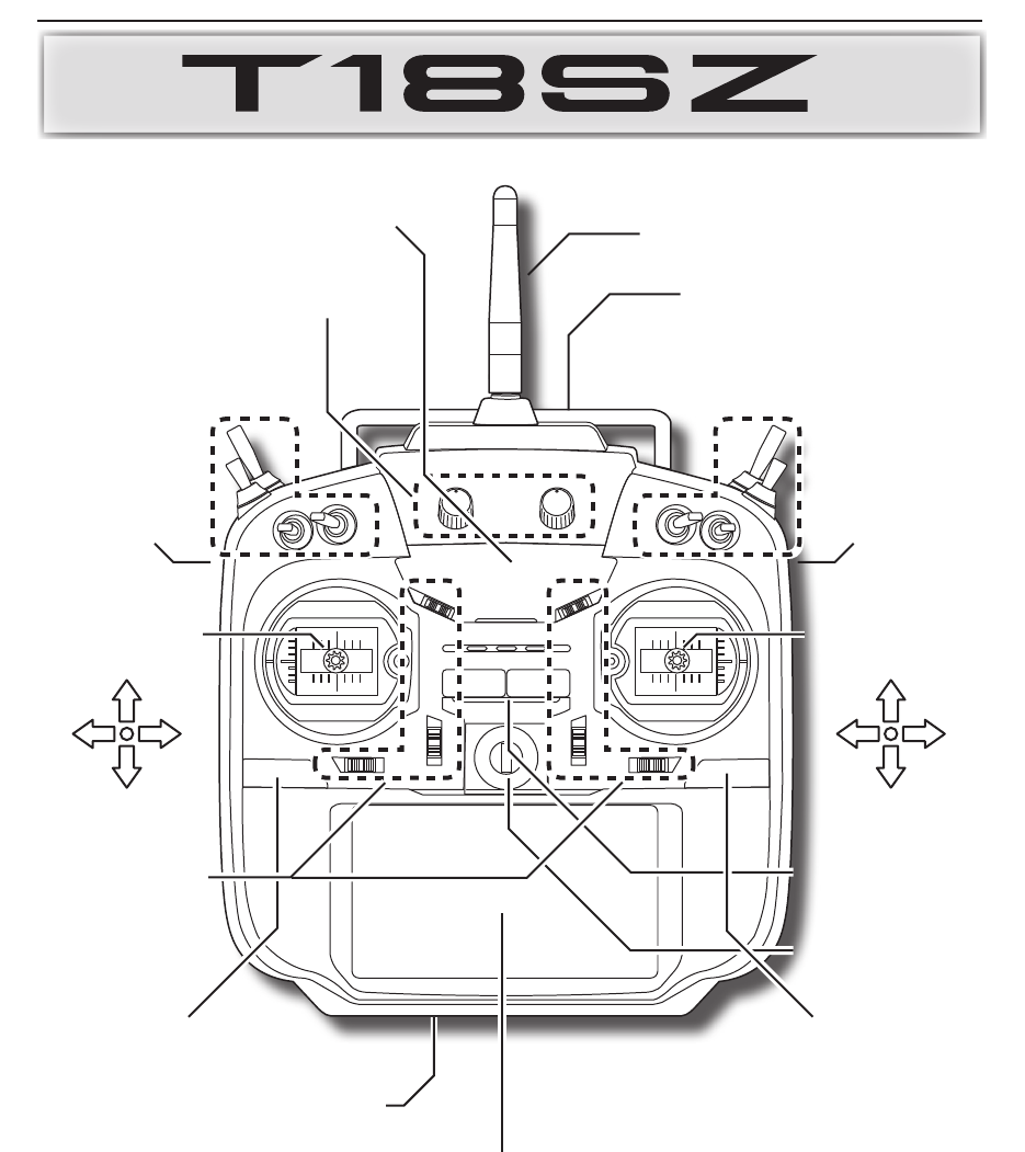
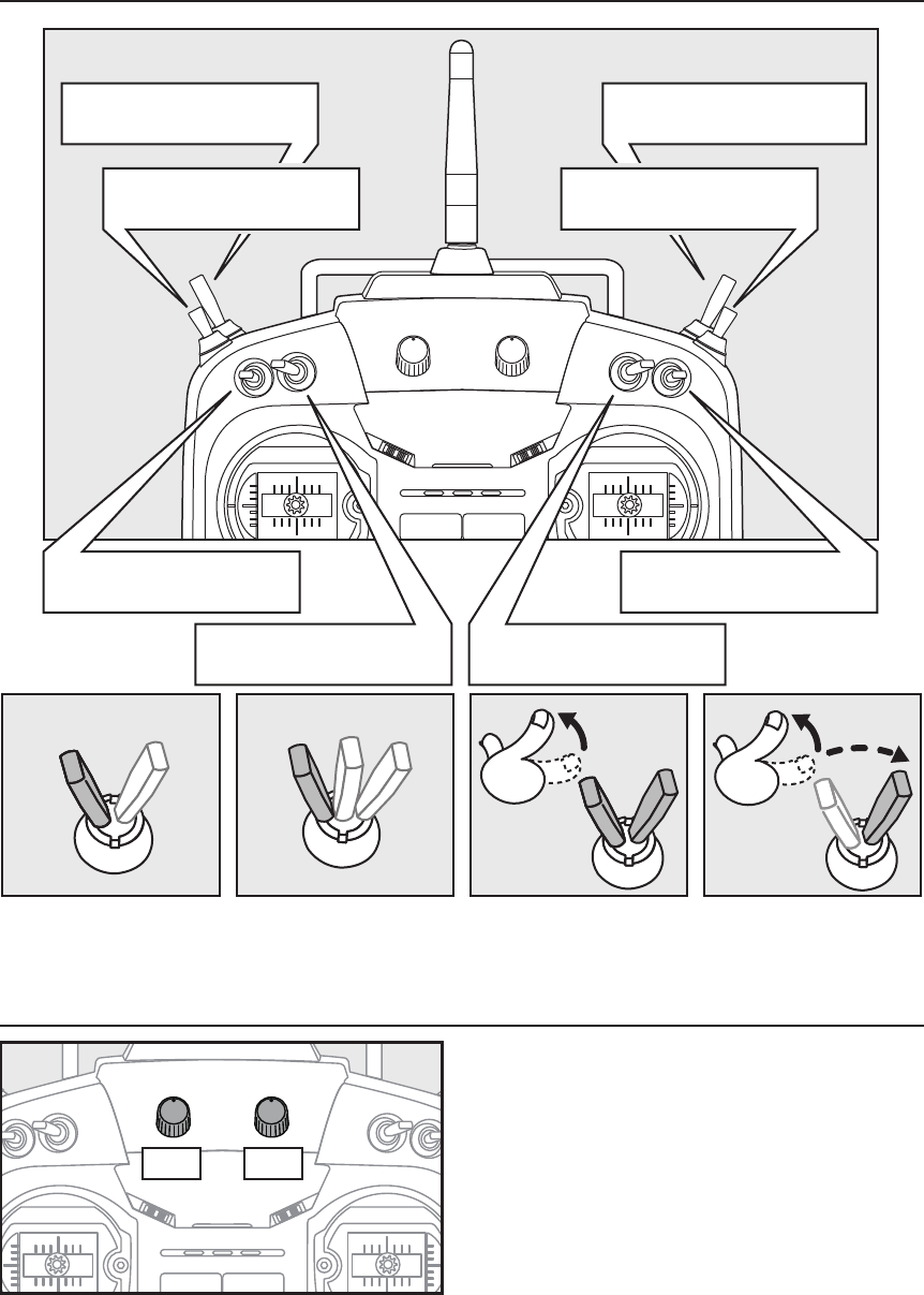
Transmitter controls
●Antenna
● Carrying handle
● Stick
● Stick
● Power Switch
● Hook
● Monitor LED
● Dial LD.RD
● Slide lever
RS
● Slide lever
LS
● U.MENU/MON. Button
(User menu/Servo monitor)
● HOME/EXIT Button
● Color LCD display touch panel
● Battery cover
● Switch
SC.SD.SG.SH
● Switch
SA.SB.SE.SF
● Digital
trim
T1 ~ T6
J2J3
J1J4
14 <Before Use>
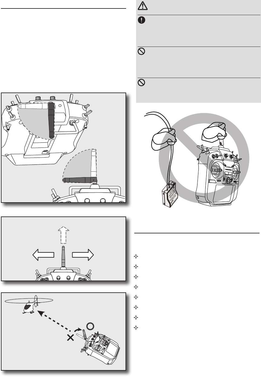
Transmitter's Antenna:
As with all radio frequency transmissions, the
strongest area of signal transmission is from the
sides of the transmitter's antenna. As such, the
antenna should not be pointed directly at the model.
If your flying style creates this situation, easily
move the antenna to correct this situation.
FASSTest mode → Light Blue light
FASST mode → Green light
S-FHSS mode → Yellow-green light
RF-OFF → Violet light
Starting → Red light
Trainer Student → Blue light
Range check mode → Slow blinking
FASSTest receiver link mode → Fast
blinking
Monitor LED display
The status of the transmitter is displayed by LED
at the upper part of the front of a T18SZ.
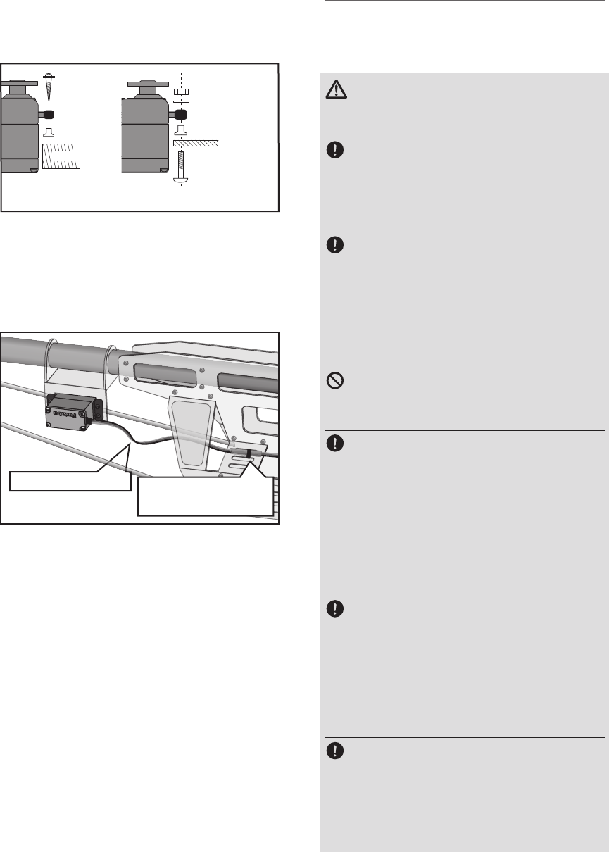
•Rotating antenna
The antenna can be rotated 90 degrees and angled
90 degrees. Forcing the antenna further than this
can damage it. The antenna is not removable.
CAUTION
Please do not grasp the transmitter's
antenna during ight.
Doing so may degrade the quality of the RF
transmission to the model
Do not carry the transmitter by the
antenna.
There is the danger that the antenna wire will break and
operation will become impossible.
Do not pull the antenna forcefully.
There is the danger that the antenna wire will break and
operation will become impossible.
90°
90°
Low power
High power High power
If you have a transmitter
at an angle of a figure, an
antenna will be good to use
it, bending 90 degrees.
It is not good for
there to be a model
on flight in the
direction tip of an
antenna.
15
<Before Use>
Stick control
*If THR stick is high, the next WARNING screen will come out. Moreover, if a power
supply is switched on while SW set by WARNING setup has been ON, it will be
indicated by WARNING.
Yawing axis
Pitching axis
Elevator Stick
Aileron stick
Throttle stick
Engine/motor
Power
Rudder stick
Roll axis
Power OFFPower ON
Throttle Stick Slow
Power Switch Power Switch Power Switch
Right Push Right and Left Push Right or Left Long Push
or
1. Turn on the transmitter power switch.
2. Turn on the receiver or speed control power switch.
Always be sure the motor/engine is stopped.
1. Turn o the receiver or speed control power switch.
2. Then turn o the transmitter power switch.
ON OFF
OFF
ON
Turning on the power switches
If the power switches are turned o in the opposite order the model may unexpectedly run out of control and
cause a very dangerous situation.
Turning o the power switches
How to turn transmitter power ON/OFF
When turning on the power, the T18SZ transmitter will begin emmiting RF automatically after it
conrms the surrounding RF conditions. The status of the transmitter is displayed by LED at the upper
part of the front of a T18SZ.
16 <Before Use>
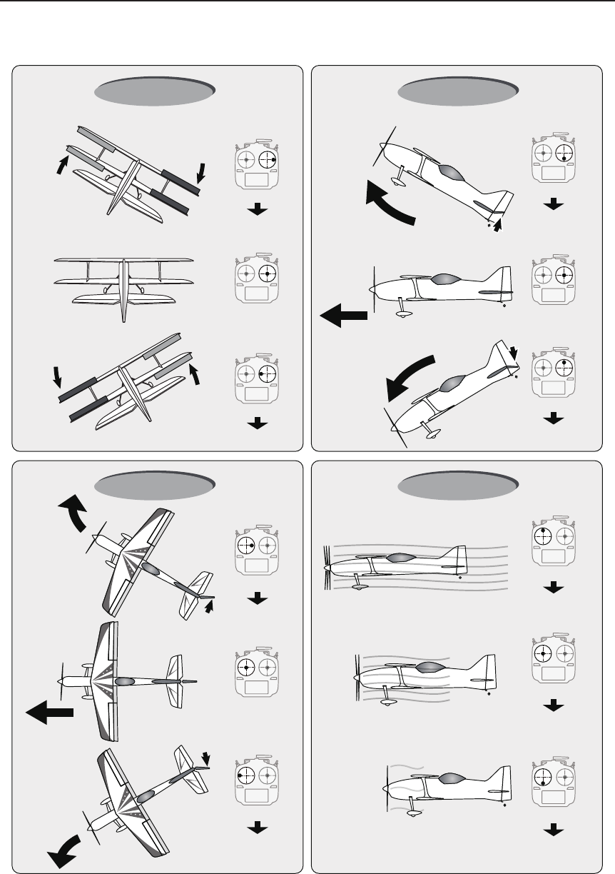
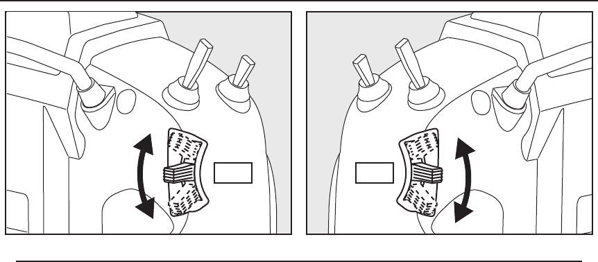
Stick control : Airplane Example
A general model example. (There is also a dierent operational model.)
Right roll
Left roll
Straight
A rudder is to
the right.
A rudder is to
the left.
The left aileron
is in the down.
The left aileron
is in the up.
Level flight Level flight
The right aileron
is to the up.
The right
aileron is to
the down.
Elevator is a
up.
Elevator is a
down.
Aileron stick
To the right
Neutral Neutral
Nose Up
Nose Down
Middle
Hight
Slow
Roll axis Control
Yaw axis Control Throttle Control
Elevator stick
UP
(moved to the bottom)
Elevator stick
DOWN
(moved to the top)
Aileron stick
To the left
Pitch axis Control
Rudder stick
To the right
Neutral
Rudder stick
To the left
Nose Right
Nose Left
Throttle stick
MIDDLE
(neutral)
Throttle stick
HIGHT
(moved to the top)
Throttle stick
SLOW
(moved to the bottom)
17
<Before Use>
Stick control : Helicopter Example
A general model example. (There is also a dierent operational model.)
Right roll
Left roll
Straight
Hovering
Rise
Descent
Level flight
Level flight
Aileron stick
To the right
Neutral Neutral
Nose Up
Nose Down
Middle
HightPitch Up
Pitch Down
Slow
Roll axis Control
Yaw axis Control Throttle /Pitch Control
Elevator stick
UP
(moved to the bottom)
Elevator stick
DOWN
(moved to the top)
Aileron stick
To the left
Pitch axis Control
Rudder stick
To the right
Neutral
Rudder stick
To the left
Nose Right
Nose Left
Throttle stick
MIDDLE
(neutral)
Throttle stick
HIGHT
(moved to the top)
Throttle stick
SLOW
(moved to the bottom)
18 <Before Use>
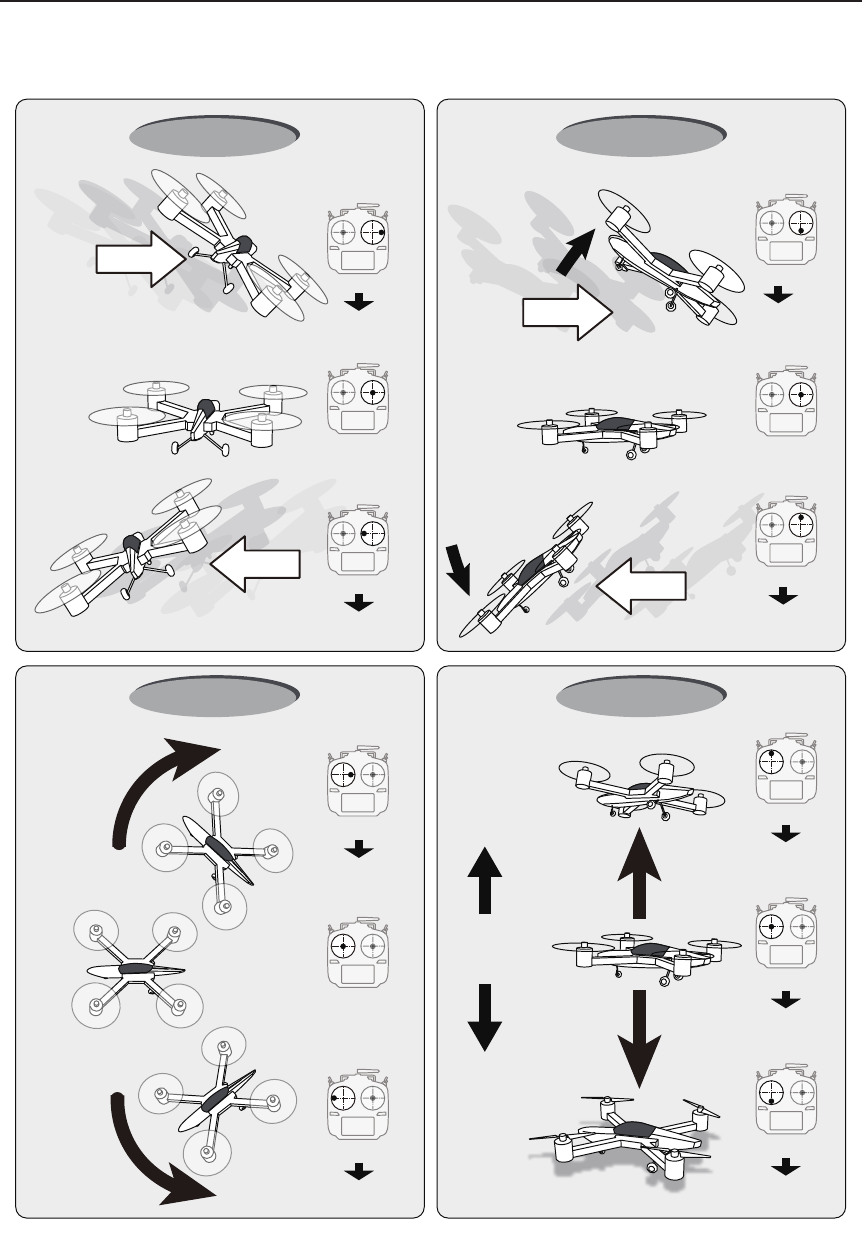
Stick control : Multicopter Example
A general model example. (There is also a dierent operational model.)
Stop
Right roll
Right slide
Back slide
Front slide
Left slide
Left roll
Hovering
Rise
Descent
Hovering
Level flight Hovering
Level flight
Hovering
Level flight
Aileron stick
To the right
Neutral Neutral
Nose Up
Nose Down
Roll axis Control
Yaw axis Control Throttle Control
Elevator stick
UP
(moved to the bottom)
Elevator stick
DOWN
(moved to the top)
Aileron stick
To the left
Pitch axis Control
Rudder stick
To the right
Neutral
Rudder stick
To the left
Nose Right
Nose Left
Throttle stick
MIDDLE
(neutral)
Throttle stick
HIGHT
(moved to the top)
Throttle stick
SLOW
(moved to the bottom)
19
<Before Use>
The volume LD and RD knobs allow analog
input.
*The T18SZ transmitter beeps when the volume knob reaches
the center position.
*You can use each setting screen of the mixing functions to
select volumes and dene the direction of a movement.
Volume
SA : 3 positions; Alternate;
Short lever
SD : 3 positions; Alternate;
Short lever
SB : 3 positions; Alternate;
Long lever
SC : 3 positions; Alternate;
Long lever
SF : 2 positions; Alternate;
Long lever
Alternate2 positions Momentary3 positions
SH : 2 positions; Momentary;
Long lever
LD RD
SG : 3 positions; Alternate;
Short lever
SE : 3 positions; Alternate;
Short lever
Switch (SA-SH)
*Self retum
20 <Before Use>
Digital Trims T1-T6
Digital trim operational example
T1T2 T4 T3
T5T6
Elevator neutral
Down
◆When an airplane nose up though an
elevator stick is neutral.
◆When an airplane nose down though
an elevator stick is neutral.
◆It's adjusted so that it may fly levelly.
◆Elevator trim to down
◆Elevator trim to up
Elevator neutral
Up
This transmitter is equipped with 6 digital trims.
Each time you press a trim button, the trim position
moves one step. If you continue pressing it, the trim
position starts to move faster. In addition, when
the trim position returns to the center, the tone will
change. You can always monitor trim positions by
referencing the LCD screen.
*You can select the trim step amount and the display unit
on the home screen on the T1-T6 setting screen within the
linkage menu.
Note: The trim positions you have set will be stored in the
non-volatile memory and will remain there.
The upper digital trimmers T5 and T6 offer
analog input.
*You can select a slide lever and set the movement direction
on the setting screen of mixing functions.
21
<Before Use>
LS RS
Slide Lever
LS (right), RS (Left):
The Linear Slider LS and RS offer analog input.
*The T18SZ transmitter beeps when the lever comes to the center.
*You can select a slide lever and set the movement direction on the setting screen of mixing functions.
22 <Before Use>
Touch Panel
●You may use this tool
as a stylus pen.
Home/Exit and U.menu/Mon.
Home/Exit
Button
U.menu/Mon
Button
Touch the panel with your nger or the attached
stylus pen, which is also used as a toolbox, to enter
data.
*Plastic lm is attached to the touch panel. Please be careful so
that you don't scratch the touch panel with anything hard such
as a metal object. Don't push the touch panel with excessive
force or drop anything on the panel.
*Although you may find some air bubbles under the plastic
panel due to environmental changes such as temperature, it is
not a defect and will cause no problems.
*Color LED is made from many pixels. Some pixels hold
lighting. Moreover, some pixels go out. And a screen may
icker. Such condition is the characteristics of color LED. It
is not failure.
Stylus pen
A rubber cap is attached to the stylus pen/
toolbox. You may use this stylus with rubber
cap when operating the touch panel. The
stylus allows more precise operation than
fingers without fear of damaging the panels
surface.
Press To Servo Monitor display
Press and hold To Model Select display
Home/Exit:
U.menu/Mon:
Press Return to the previous
screen
Press and hold Return to the Home screen
It pushes from
HOME screen. To TELEMETRY display
*There is no function of U.menu (user menu).
It is due to add by update.
23
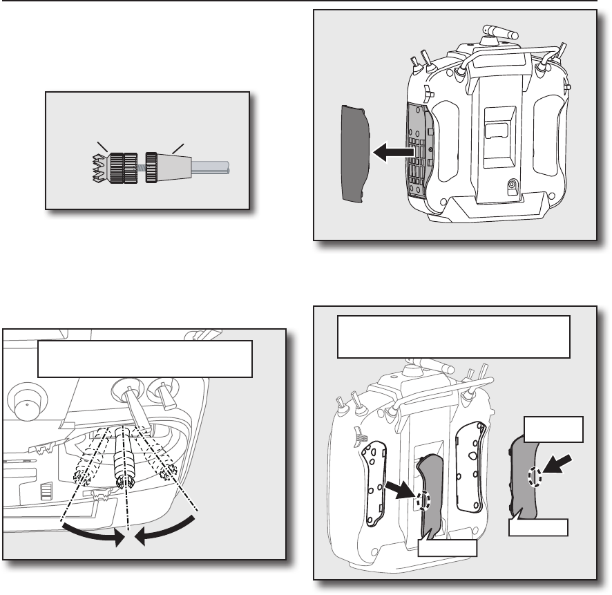
<Before Use>
Stick Adjustment
Lever Head
A B
Lever Head
Adjustment of the stick lever length
You can adjust the length of stick levers, as you
like. It is recommended to adjust the length of the
sticks in line with your hand size.
1. Hold the lever head "B" and turn the lever
head "A" counter-clockwise. The lock will be
released.
2. Turn the lever-head "A" clockwise as you hold
the lever-head "B" after placing it as you like.
Adjustment of stick lever tension
The tension of the self-return type stick lever can
be adjusted.
1. First, Remove the battery cover on the
bottom of the transmitter. Next, unplug the
battery wire and remove the battery from
the transmitter.
2. Next, using a hand, remove the transmitter's
side cover (rubber). When using Mode 1, you
will need to remove the side cover to expose
the tension screw.
Side cover
• Rear Grip
It removes
from here
*It is dicult to remove rear grips from the central
site of a transmitter.
Therefore, remove from the outside of rear grips.
• Rear Grip
4. Use a small Phillips screwdriver to adjust the
spring strength as you prefer by turning the
adjusting screw of the stick you want to
adjust.
*Turning the screw clockwise increases the tension.
CAUTION: If you loosen the screw too much,
it can interfere with the operation of the
sticks internally.
The stick can be adjusted to how
quickly it returns to neutral.
3. Using your hand remove the transmitters rear
rubber grips.
24 <Before Use>
Screw is clockwise.
Stick tension maximum
Stick tension minimum
Screw is counter-clockwise.
1.5mm hexagonal wrench
1.5mm hexagonal wrench
•Stick Tension (J1)
(Mode 1/2)
•Stick Tension (J2)
(Mode 2)
•Stick Tension (J4)
(Mode 1/2)
•Stick Tension (J3)
(Mode 1)
5. At the end of adjustment, re-install the side
cover and rear grips.
Use the attached 1.5mm hexagonal wrench
(inside stylus) to turn the screw clockwise to adjust
the stick outwards, or counter-clockwise to tilt it
inward.
Note: Be careful not to turn the screw too far
counterclockwise as it could fall out.
Stick Adjustment
Adjustment of the stick lever angle
You can make fine adjustments to the angle of
a stick lever either inwards or outwards from the
center stick position.
25
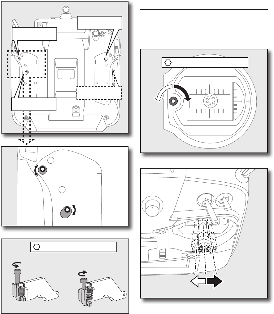
<Before Use>
CAUTION
Be sure to turn off the power to the
transmitter before inserting or removing
the SD card.
As the SD card is a precision device, do not
use excessive force when inserting.
SD card reader/writer
Saving model data and update files (released
from Futaba) into the SD card, you can use those
files on your T18SZ transmitter. Equipment for
reading and writing SD cards is available at most
electronics stores.
Stored data
When you have a problem of saving or reading
data after a long period of use, please get a new SD
card.
*We do not have the responsibility of compensating any
failure or damage to the data stored in the memory card no
matter what the reason is. Be sure to keep a backup of your
important data in your SD card.
SD Card (secure digital memory card) (not included)
SD card slot
②The SD card slot is
show here in the
figure below.
*Don't mistake the both sides/ the direction of
SD card.
SD card slot
Battery cover
The T18SZ transmitter model data can be stored by using any commonly found SD card. When T18SZ
transmitter update software is released, the software is updated using an SD card. The T18SZ is capable of
using SD cards with a memory size between 32MB and 2GB.
① A side battery cover
is opened.
③ When the SD card
is pressed in once
again, the card will
be released from the
card slot. and can be
removed.
Inserting/removing the SD card
26 <Before Use>
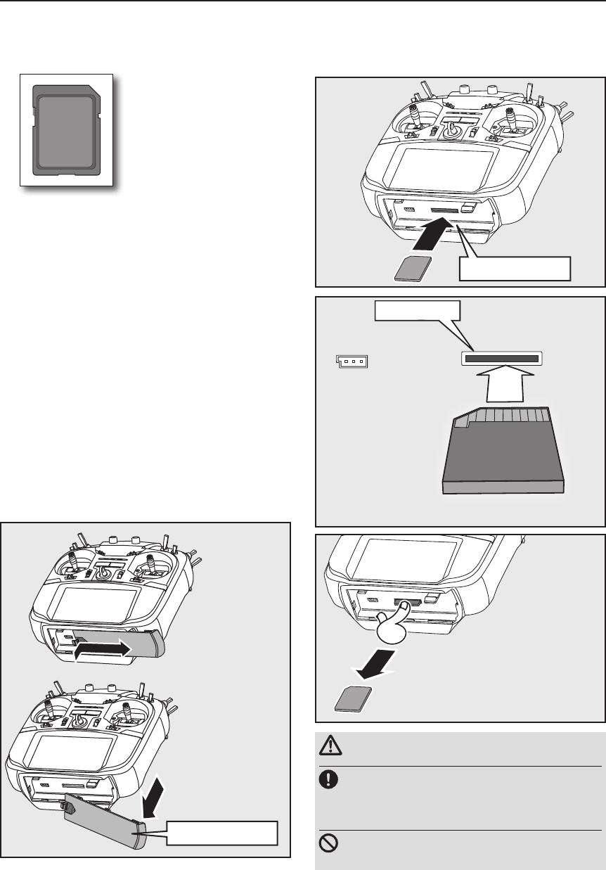
Connector for trainer function
When you use the trainer function, connect the
optional trainer cable between the transmitters for
teacher and student.
*You can set the trainer function on the Trainer Function
screen in the System menu.
Connector/Plug
WARNING
Do not connect any other chargers except the
special charger to this charging connector.
*If you take out the LiFe battery FT2F2100BV2 from the
transmitter, you can use the optional balance charger LBC-
4E5 corresponding to LiFe battery.
Connector for battery charger
This is the connector for charging the LiFe
battery FT2F2100BV2 that is installed in the
transmitter. Do not use any other chargers except
the attached special charger corresponding to LiFe
battery.
Rubber cover
Trainer
Connector
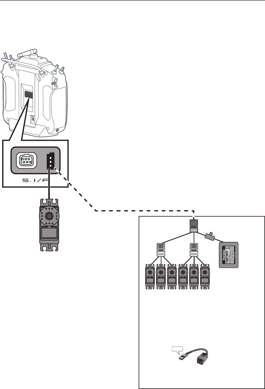
S.BUS (S.I/F)
Connector
Charge
Plug
Earphone
Plug
S.BUS connector (S.I/F)
When setting an S.BUS servo and telemetry
sensor, connect them both here.
(Supply power by 3-way hub or 2-way cord.)
Earphone plug
Connecting a stereo headphone to this plug, the
speech information of telemetry can be heard.
27
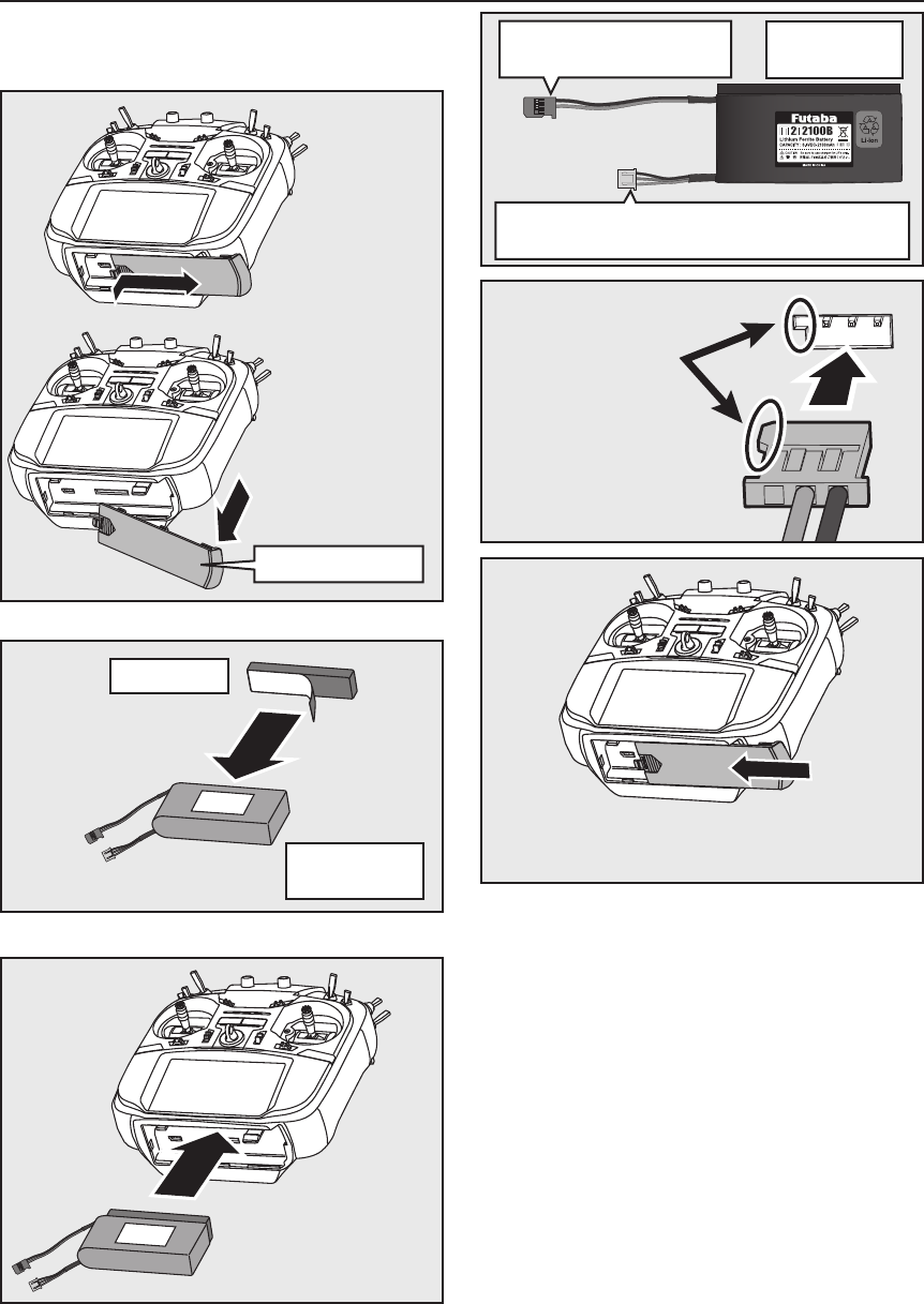
<Before Use>
Sponge tape
This 2P connector to be
connected to a transmitter.
FT2F2100B V2
LiFe Battery
Transmitter LiFe Battery FT2F2100B V2
③ Connect the battery
connector.
④ Close the battery cover completely.
Inserting/removing the FT2F2100B V2
Battery cover
① A side battery cover
is opened.
② A sponge tape is
stuck on a battery.
③ Install the battery
in a transmitter.
FT2F2100B V2
LiFe Battery
The balance charge connector is not connected in
the state where the battery is set to a transmitter.
28 <Before Use>
Battery removal
Note: If you remove the battery while the
power is on, the data you have set will not
be saved.
1. Open the battery cover.
2. Disconnect the battery connector.
3. Close the battery cover completely.
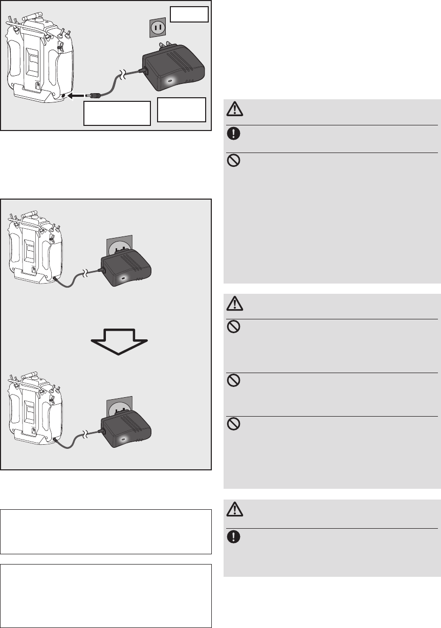
1.Plug the transmitter cord of the special
charger into the charging jack on the side of
the transmitter.
2. Plug the charger into an AC outlet.
3. Check that the charging LED lights.
WARNING
Be careful not to drop the battery.
Never disconnect the battery connector
from the T18SZ transmitter after turning
off the power until the screen is completely
blank and the transmitter has shut down
completely.
* Internal devices such as memories may be damaged.
* If there is any problem, the message "Backup Error" will
be shown the next time when you turn on the power of the
transmitter. Do not use the transmitter as it is. Send it to the
Futaba service center.
WARNING
Never plug it into an outlet other than the
indicated voltage.
*Plugging the charger into the wrong outlet could result in
an explosion or re.
Do not insert and remove the charger when
your hands are wet.
*It may cause an electric shock.
Do not overcharging /overdischarging the
battery.
*Overcharging/Overdischarging a battery can result in burns,
re, injuries, or loss of sight due to overheating, breakage,
or electrolyte leakage.
CAUTION
When the charger is not in use, disconnect it
from the AC outlet.
* Do this to prevent accidents and to avoid overheating.
When the battery will not be used for a long time, to prevent
it from deteriorating we recommend that it be kept in about
the half capacity state instead of fully charged. Also be care-
ful that the battery does not enter the over-discharged state
due to self-discharge.
Periodically (about every 3 months) charge the battery.
The charging time when charging the FT2F2100BV2 battery
with the optional special charger is approximately 3 hours.
However, when the battery has not been used for some time,
repeat charging 2 or 3 times to activate the battery.
Red sold
Charging
Charge completion
Green sold
Red blink
or
4. Disconnect the charg plug.
5. Disconnect the AC plug.
Charger
LBC-34D P
AC100V
To transmitter
charging jack
Charge of a LiFe battery
29
<Before Use>
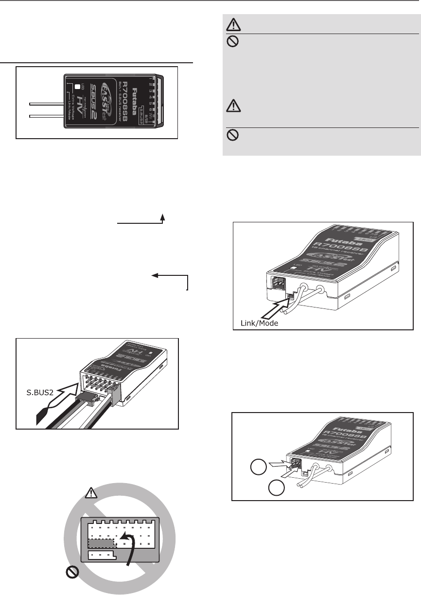
Link/Mode Switch
Use the small plastic screw driver that was
included with your receiver.
The Link/Mode Switch is also used for the CH
mode selection.
Extra Voltage Connector
Use this connector when using a voltage
telemetry device to send the battery voltage (DC0
~ 70V) from the receiver to the transmitter.
You will need to purchase the optional External
Voltage input cable (CA-RVIN-700) FUTM5551.
You can then make a cable with an extra
connector to the External voltage connector.
Before using the receiver, be sure to read the
precautions listed in the following pages.
Receiver R7008SB
Connector
"1 through 6": outputs for the channels 1
through 6
"7/B": outputs of 7 channels and power.
"8/SB": outputs of 8 channels or S.BUS port.
[S.BUS Servo S.BUS Gyro ]
*When using 8/SB as S.BUS, you have to set
CH MODE of the following page to mode B or
mode D.
"S.BUS2": outputs of S.BUS2 port.
[S.BUS2 Servo S.BUS2 Gyro Telemetry Sensor ]
*When using 9 or more channels, use an S.BUS
function or use a second R7008SB and link both
to your transmitter.
Connector insertion
Firmly insert the connector in the direction
shown in the gure. Insert the S.BUS2 by turning
it 90 degrees.
+
-
Do not connect either a switch
or battery in this manner.
Receiver
Danger
Danger
Don't connect a connector, as shown in a
before gure.
*It will short-circuit, if it connected in this way. A short
circuit across the battery terminals may cause abnormal
heating, re and burns.
Warning
S.BUS2 connectors
Don't connect an S.BUS servo / gyro to
S.BUS2 connector.
LED Monitor
This monitor is used to check the CH mode of
the receiver.
Receiver nomenclature
30 <Before Use>
R7008SB CH Mode
The R7008SB receiver is a very versatile
unit. It has 8 PWM outputs, S.BUS and S.BUS2
outputs. Additionally the PWM outputs can be
changed from channels 1-8 to channels 9-14. If
you only desire to use it as an 8 channel receiver
(without S.BUS), it can be used without any
setting changes.
The T18SZ has the ability to link to two
R7008SB receivers. One of them outputting
channels 1-8 and the other outputting channels
9-14 giving you 14 PWM channels. Instructions
for this configuration and S.BUS operation
follow.
[How to change the R7008SB Channel mode.]
1. Press and hold down the Link/Mode button
on the R7008SB receiver.
2. Turn the receiver on while holding down
the Link/Mode button. when the LED
begins to blink green/red the button may
be released.
3. The LED should now be blinking red in one
of the patterns described by the chart
below.
4. Each press of the Mode/Link button
advances the receiver to the next mode.
5. When you reach the mode that you wish
to operate in, press and hold the Mode/
Link button for more than 2 seconds.
6. Once locked into the correct mode the
LED will change to a solid color.
7. Please cycle the receiver(s) power off and
back on again after changing the Channel
Mode.
Receiver connector
Setting channel
Mode A
1 ~ 8CH
Mode B
1 ~ 7CH
Mode C
9 ~ 14CH
Mode D
9 ~ 14CH
1 1199
2 2 2 10 10
3 3 3 11 11
4 4 4 12 12
5 5 5 13 13
6 6 6 14 14
7/B 7 7 - -
8/SB 8 S.BUS - S.BUS
Red LED blink 1time 2time 3time 4time
R7008SB CH MODE TABLE
Danger
Don't touch wiring.
* There is a danger of receiving an electric shock.
Do not short-circuit the battery terminals.
* A short circuit across the battery terminals may cause
abnormal heating, re and burns.
Please double check your polarity ( +and
-) when hooking up your connectors.
* If + and - of wiring are mistaken, it will damage,
ignite and explode.
Don’t connection to Extra Voltage before
turning on a receiver power supply.
31
<Before Use>
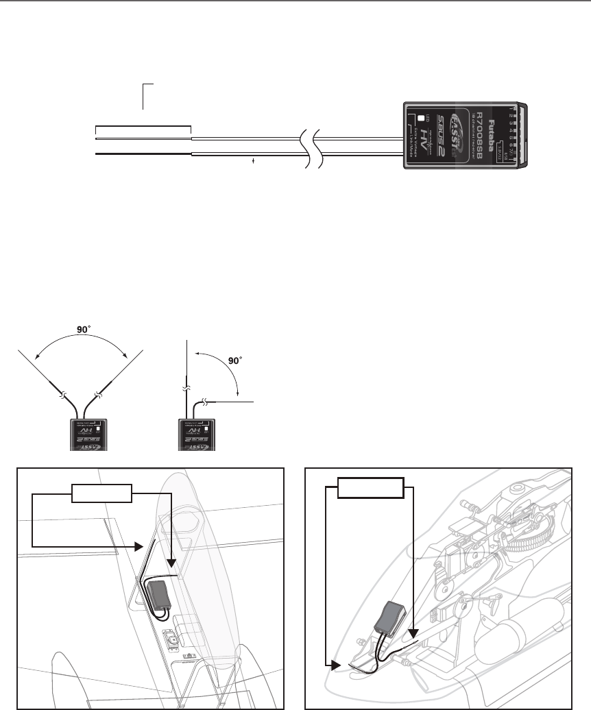
Receiver's Antenna Installation
The R7008SB has two antennas. In order to maximize signal reception and promote safe modeling
Futaba has adopted a diversity antenna system. This allows the receiver to obtain RF signals on both
antennas and y problem-free.
To obtain the best results of the diversity
function, please refer to the following
instructions:
1. The two antennas must be kept as straight
as possible. Otherwise it will reduce the
effective range.
2. The two antennas should be placed at 90
degrees to each other.
This is not a critical figure, but the most
important thing is to keep the antennas
away from each other as much as possible.
Larger models can have large metal
objects that can attenuate the RF signal. In
this case the antennas should be placed
at both sides of the model. Then the best
RF signal condition is obtained at any ying
attitude.
3. The antennas must be kept away from
conductive materials, such as metal,
carbon and fuel tank by at least a half
inch. The coaxial part of the antennas does
not need to follow these guidelines, but do
not bend it in a tight radius.
4. Keep the antennas away from the motor,
ESC, and other noise sources as much as
possible.
*The two antennas should be placed at 90 degrees to each other.
*The illustration demonstrates how the antenna should be placed.
*Receiver Vibration and Waterproofing: The receiver contains precision electronic parts. Be sure to avoid vibration,
shock, and temperature extremes. For protection, wrap the receiver in foam rubber or other vibration-absorbing
materials. It is also a good idea to waterproof the receiver by placing it in a plastic bag and securing the open end of the
bag with a rubber band before wrapping it with foam rubber. If you accidentally get moisture or fuel inside the receiver,
you may experience intermittent operation or a crash. If in doubt, return the receiver to our service center for service.
Antenna Antenna
Antenna
*Must be kept as straight as possible.
Coaxial cable
R7008SB Receiver
32 <Before Use>
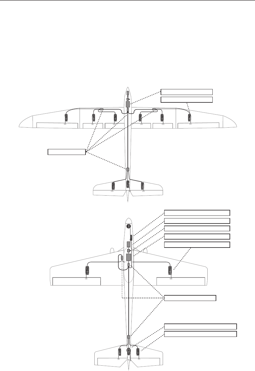
*If the servo case contacts the airframe directly, vibration
will travel to and possibly damage the servo.
Rubber
grommet
Brass eyelet
Wood screw
Servo mount
2.3-2.6mm nut
washer
Rubber
grommet
Brass eyelet
Servo mount
2.3-2.6mm screw
(Helicopter) (Airplane/Glider)
Servo lead wires
To prevent the servo lead cable from being
broken by vibration during flight, provide a
little slack in the cable and fasten it at suitable
points. Periodically check the cable during daily
maintenance.
Fasten about 5-10cm
from the servo outlet so
that the lead wire is neat.
Margin in the lead wire.
Mounting the power switch
When mounting a power switch to an
airframe, make a rectangular hole that is a little
larger than the total stroke of the switch so
that you can turn the switch ON/OFF without
binding.
Avoid mounting the switch where it can be
covered by engine oil and dust. In general, it is
recommended to mount the power switch on the
side of the fuselage that is opposite the mufer.
Safety precautions when
you install receiver and
servos.
WARNING
Connecting connectors
Be sure to insert the connector until it
stops at the deepest point.
How to protect the receiver from vibration
and water
Wrap the receiver with something soft
such as foam rubber to avoid vibration.
If there is a chance of getting wet, put the
receiver in a waterproof bag or balloon to
avoid water.
Receiver's antenna
Never cut the receiver's antenna. Do not
bind the receiver's antenna with the cables
for servos.
Locate the receiver's antenna as far as
possible from metals or carbon fiber
components such as frames, cables, etc.
*Cutting or binding the receiver's antenna will reduce the
radio reception sensitivity and range, and may cause a
crash.
Servo throw
Adjust your system so that pushrods will
not bind or sag when operating the servos
to the full extent.
*If excessive force is continuously applied to a servo, the
servo could be damaged due to force on the gear train
and/or power consumption causing rapid battery drain.
Mounting servos
Use a vibration-proof rubber (such as
rubber grommet) under a servo when
mounting the servo on a servo mount. And
be sure that the servo cases do not touch
directly to the metal parts such as servo
mount.
Mounting the Servo
33
<Before Use>
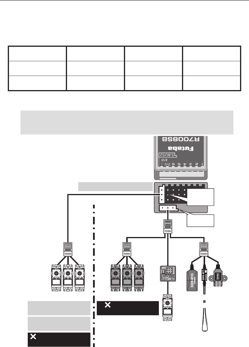
S.BUS/S.BUS2 Installation
This set uses the S.BUS/S.BUS2 system. The wiring is as simplied and clean mounting as possible,
even with models that use a large number of servos. In addition, the wings can be quickly installed to the
fuselage without any erroneous wiring by the use of only one simple wire, even when there are a large
number of servos used.
●When using S.BUS/S.BUS2, special settings and mixes in your transmitter may be unnecessary.
●The S.BUS/S.BUS2 servos memorize the number of channels themselves. (settable with the T18SZ)
●The S.BUS/S.BUS2 system and conventional system (receiver conventional CH used) can be mixed.
Receiver: R7008SB
Battery: FR2F1800 ( Optional )
Switch: HSW-L
Throttle servo: BLS173SV ( Optional )
Aileron servo: BLS174SV×2 ( Optional )
Elevator servo: BLS173SV×2 ( Optional )
Rudder Servo: BLS175SV×1 ( Optional )
HUB×3 ( Optional )
Receiver: R7008SB
Servo: S3172SV×9 ( Optional )
HUB×4 ( Optional )
S.BUS Glider usage example
S.BUS Aerobatic plane usage example
34 <Before Use>
S.BUS Wiring example
Battery
Switch
Receiver
S.BUS
Port
(8/SB)
*When using 8/SB as S.BUS, you must set the receiver to
Mode B or Mode D. See R7008SB CH MODE TABLE.
Battery
S.BUS
Extension
Cable
Terminal box
Hub
Hub Hub
Hub
(Another power supply)
S.BUS Servo
S.BUS Servo S.BUS Servo
●S.BUS Servo
Since the channel number is memorized by
the S.BUS itself, any connector can be used.
When the SBD-1 (sold separately) is used,
ordinary servos can be used with the S.BUS
system.
*SBD-1 cannot be used by S.BUS2 port.
●When separate power
supply used
When a large number of servos
are used or when high current
servos are used, the servos can be
driven by a separate power supply
by using a separate Power Supply
3-way hub.
●4-Terminal box
Four connectors can be inserted
●6-Terminal box
(TB16PP)
Six connectors can be inserted
●Hub
Three connectors can be inserted.
●Hub(Another
power supply)
Used when using a separate
power supply battery.
Switch
Orange Green
WARNING
Power supply
Please make sure that you use a
battery that can deliver enough
capacity for the number and kind
of servos used. Alkaline batteries
cannot be used.
35
<Before Use>
S.BUS2 System
When using the S.BUS2 port, an impressive array of telemetry sensors may be utilized.
Receiver port S.BUS Servo
S.BUS Gyro
S.BUS2 Servo
S.BUS2 Gyro Telemetry sensor
S.BUS ○ ○ ×
S.BUS2 × (※) ○ ○
S.BUS2 TABLE
(※)Don't connect S.BUS Servo,
S.BUS Gyro to S.BUS2 connector.
S.BUS2
Port
S.BUS
Port
(8/SB)
Hub
Hub Hub Hub
Rudder Servo
S.BUS2 ServoS.BUS Servo
S.BUS2 servo
Connection is possible
S.BUS2 gyro
Connection is possible
S.BUS servo
Connection is impossible
Telemetry sensor
Connection is impossible
S.BUS2
GYRO
CH Mode is set to ModeB [D].
+
Telemetry
Sensor
S.BUS servos and gyros and S.BUS2 servos and gyros must be used in the
correct receiver ports. Please refer to the instruction manual to make sure
you connect to the correct one.
36 <Before Use>
S.BUS/S.BUS2 device setting
S.BUS/S.BUS2 servos or a telemetry sensor can be connected directly to the T18SZ. Channel setting and
other data can be entered for the S.BUS/S.BUS2 servos or sensors.
(S.BUS/S.BUS2 servo)
S.BUS/S.BUS2
device
(Telemetry sensor)
T18SZ
1. Connect the S.BUS device you want to set
with as shown in the gure.
2. Turn on the transmitter power.
3. Call the setup screen.
Servo: System Menu → S.BUS servo
Sensor: Linkage Menu → Sensor
4. Perform setting in accordance with each
screen.
5. This sets the channel and other data for each
S.BUS servo, or telemetry device to be used
with the S.BUS device or receiver.
*It is not necessary to carry out multiple
connection of the battery like a T18MZ/
T14SG.
(It will damage, if it connects.)
*When you connect to a transmitter many servos
which consume many current, please use
"Another power supply HUB".
And electric power is supplied to a servo with
another power supply.
Battery
Hub Hub
Hub
(Another power supply)
Hub
(Another power supply)
S.BUS Servo
●When separate power supply used
When a large number of servos are used or
when high current servos are used, the servos
can be driven by a separate power supply by
using a separate Power Supply 3-way hub.
Used when using a separate
power supply battery.
Switch
Green
37
<Before Use>
Telemetry System
The R7008SB receiver features bi-directional communication with a FASSTest Futaba transmitter using
the S.BUS2 port. Using the S.BUS2 port an impressive array of telemetry sensors may be utilized. It also
includes both standard PWM output ports and S.BUS output ports.
*Telemetry is available only in the FASSTest 18CH /T-FHSS mode. (FASSTest 12CH mode displays only
receiver battery voltage and extra battery voltage.)
*The telemetry function requires the corresponding receiver (R7008SB).
* Telemetry display only T18SZ ID of R7008SB was remembered to be.
Drive battery
CA-RVIN-700
S.BUS2
port
Temperature
Sensor Slot 1
Slot 2
Slot 3 ~ 5
Slot 6 ~7
Slot 8 ~ 15
Slot 16
Receiver
Battery voltage is
displayed at the transmitter.
Drive battery voltage is
displayed at the transmitter.
Switch
Terminal box
Hub
Hub
Hub
Info
Info
Info
Info
Info
Signal
RPM
Sensor
Altitude
Sensor
GPS
Sensor
Voltage
Sensor
Slot 17
Slot 31
***Sensor
***Sensor
●Telemetry sensor (sold separately)
Your aircrafts data can be checked in the
transmitter by connecting various telemetry
sensors to the S.BUS2 connector of the
receiver.
●Slot No.
Servos are classified by channel, but sensors
are classified by “slot” . Since the initial slot
No. of the T18SZ is preset at each sensor, the
sensors can be used as is by connecting
them. There are 1~31 slots.
Info
with external power
input must be less than 70V Branch
Fuse
Motor
Controller
T18SZ
31
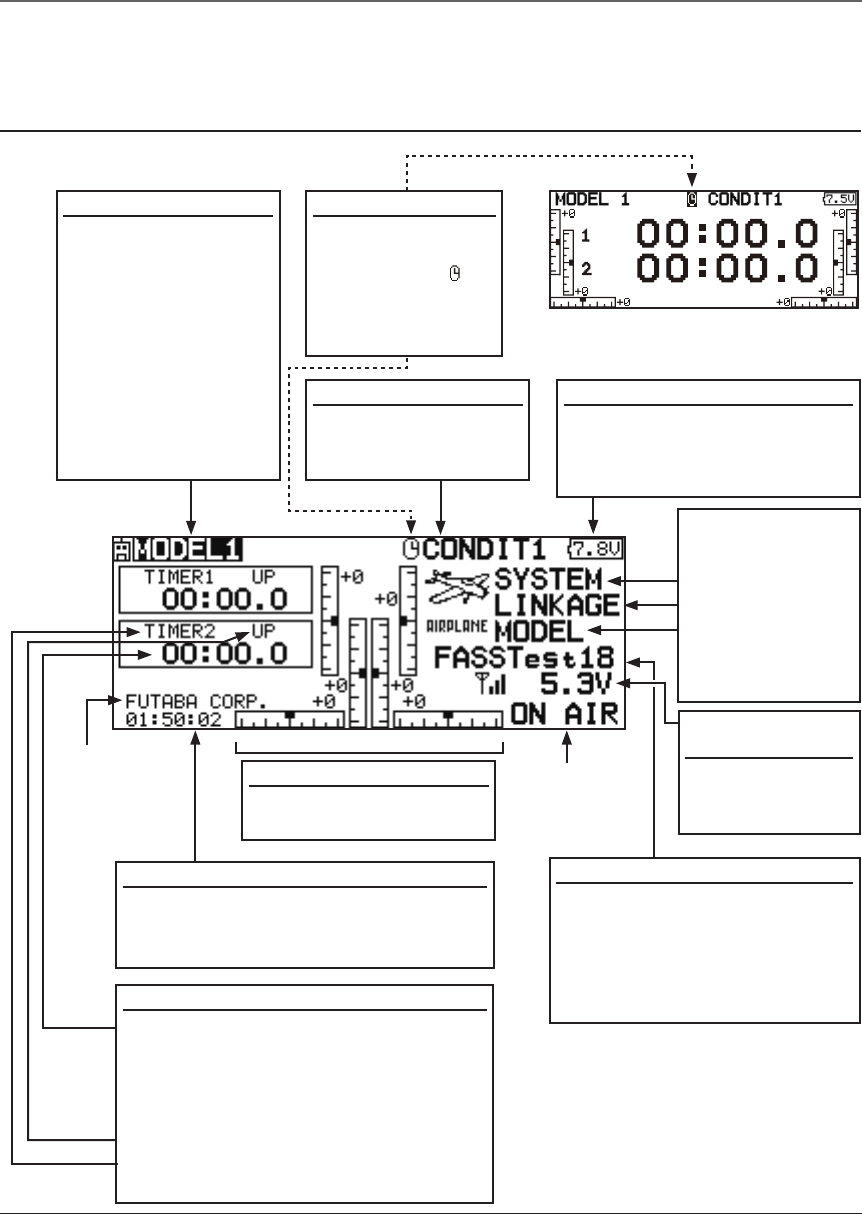
<Basic Operation>
System mode
• System(FASSTest18CH etc.)
mode is displayed here.
• Use the cursor to highlight this,
then touch the RTN button
to call the frequency set-up
screen.
Battery voltage for
receivers
• In FASSTest
mode, it is
displayed.
Timer
• Timer is displayed here.
Push the EDIT button to start/stop the
timer. (When the RTN button is touched
for 1 second, timer is reset to the initial
value.)
• Mode (UP/DN) is displayed here.
• Push the EDIT button to call the timer
setting screen.
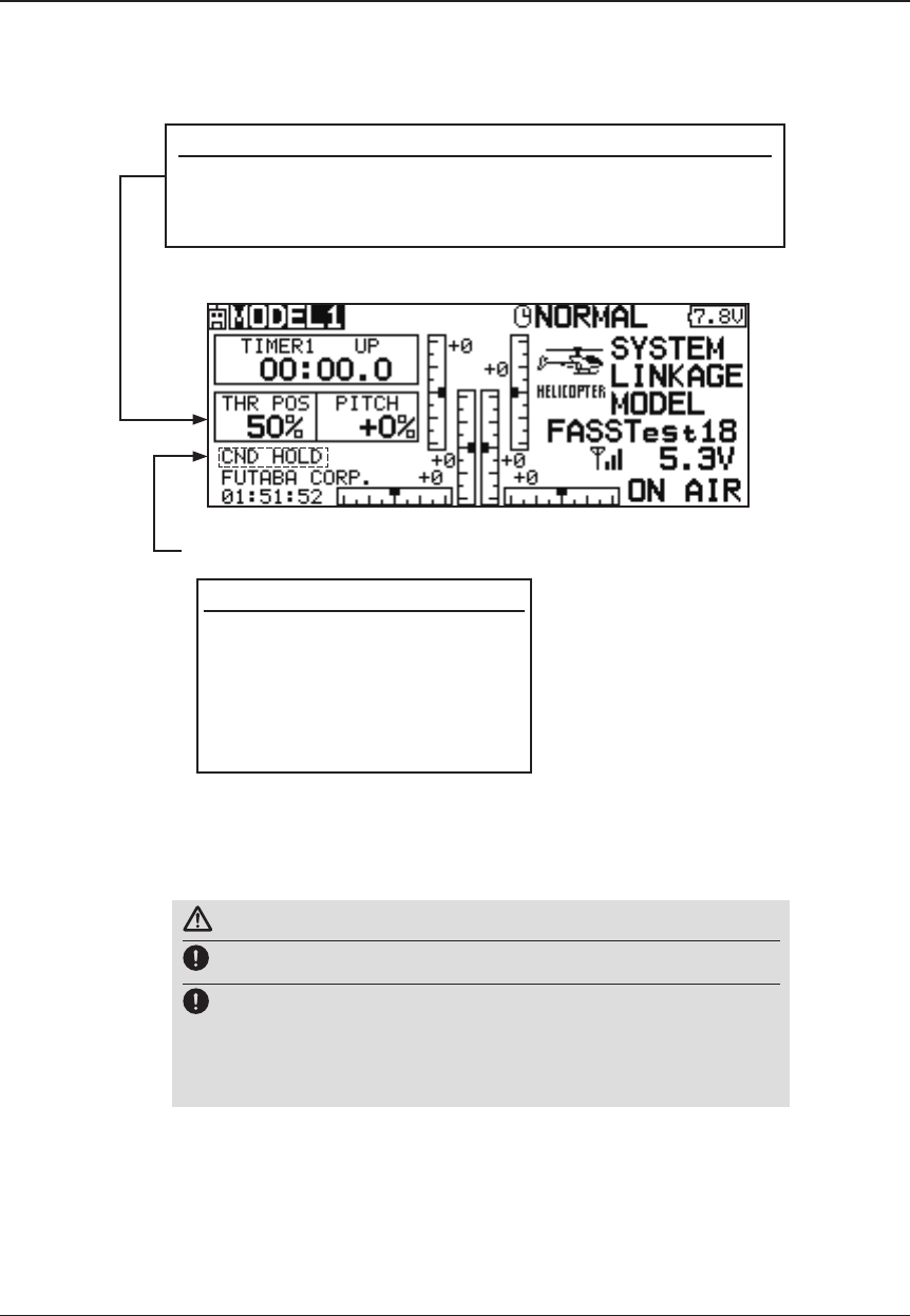
Home screen
Digital trim (T1 to T6)
• Trim position is displayed
here.
Model Name
• The model name that
is currently used is
displayed here.
•The model select
screen can now be
opened directly from
the home screen.
Move the cursor to
the model name on
the home screen,
and press the RTN
button.
User's name
System timer
• This shows the accumulated time since
the latest reset. (Each model)
(Hour):(Minute):(Second)
Use the touch sensor to select the following display area to call each setting screen, and push the EDIT
button. The setting screen appears.
(Menu)
• System
• Linkage
• Model
Push the EDIT
button to call
each Menu
screen.
●RF Indicator
Battery Indicator
• When the battery voltage
reaches 6.8V, the alarm will
beep. Land your aircraft
immediately.
Airplane/Glider Home Screen
Condition Name
• The condition name
that is currently used
is displayed here.
Timer display screen
• When the cursor
is moved to the
clock icon " " of
the home screen,
the timer display
screen appears.
BASIC OPERATION
32 <Basic Operation>
Throttle/Pitch Position Display
• Throttle and pitch position is displayed here.
Push the EDIT button to call the throttle curve or pitch curve
setting screen directly.
Helicopter Home Screen
To activate/deactivate Condition Hold:
1.Move the cursor to [CND HOLD].
2.Set the throttle stick lower than
the 1/3 point and push the EDIT
button to activate/deactivate the
condition hold function.
*For a detailed description, refer to [COND.
HOLD] function instructions.
*Condition hold operation is displayed. ("IS ON")
WARNING
Be sure to conrm the model name before ying your aircraft.
Check the battery voltage as often as possible and try to charge
the battery earlier. If the battery alarm makes a sound, land your
aircraft immediately.
*You can adjust the LCD contrast by the display setting in the system menu.
33
<Basic Operation>
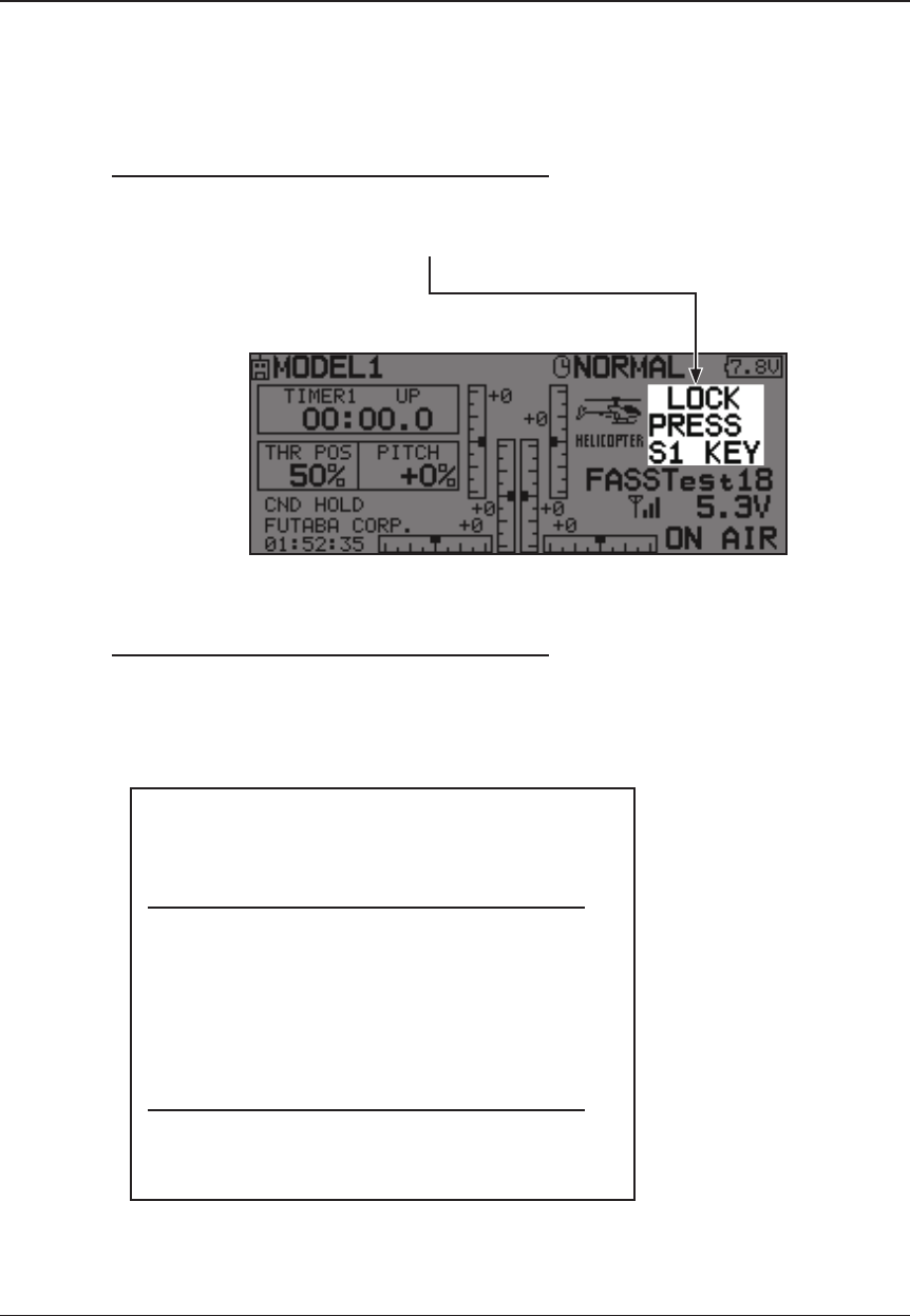
Screen lock
To prevent the data from being changed by erroneous touching of the touch sensor during flight, a
function which makes an touch sensor impossible temporarily.
How to lock
1. The home screen is displayed.
2. Press the S1 button for about 1 second.
"LOCK" is displayed and the touch sensor is
disabled.
How to unlock
1. Press the S1 button for about 1 second in the
touch sensor locked state. The touch sensor is
enabled again.
STARTUP LOCK
Auto Lock functions automatically when the
model changes or power is turned on.
*To temporarily allow access to the T18SZ programming
press and hold the S1 bitton for one second. Please note,
the Auto Lock function timer will resume immediately once
again.
AUTOMATIC LOCK
Auto Lock functions automatically when there is
no operation from the HOME screen display for a
chosen number of seconds.
*Two kinds of automatic locks can be
chosen by [DISPLAY] of [SYSTEM MENU].
34 <Basic Operation>
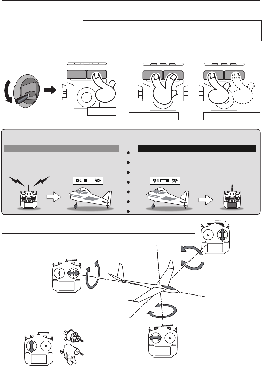
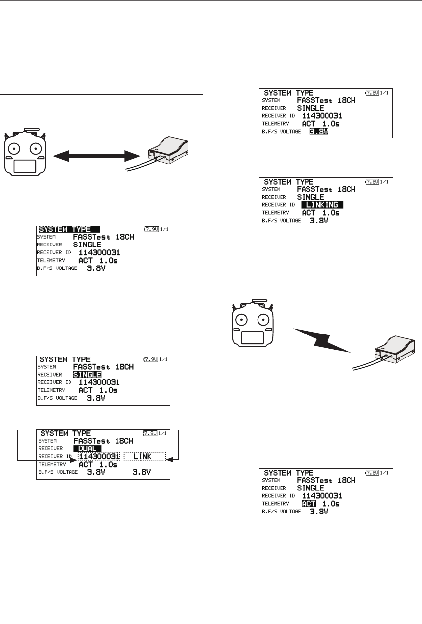
Link procedure (T18SZ/R7008SB)
Each transmitter has an individually assigned, unique ID code. In order to start operation, the receiver
must be linked with the ID code of the transmitter with which it is being paired. Once the link is made,
the ID code is stored in the receiver and no further linking is necessary unless the receiver is to be used
with another transmitter. When you purchase additional R7008SB receivers, this procedure is necessary;
otherwise the receiver will not work.
Link procedure
1. Place the transmitter and the receiver close
to each other within half (0.5m) meter.
2. Turn on the transmitter.
3. Select [SYSTEM TYPE] at the Linkage menu
and access the setup screen shown below
by touching the RTN button.
4. When you use two receivers on one model,
you must change from [SINGLE] to [DUAL].
*Only two receivers can be used. In
"DUAL", two setting items come out. Input,
respectively.
5. When changing battery fail-safe voltage
from the initial value 3.8V, voltage is
changed here.
* Only in FASSTest Mode.
6.[RECEIVER-ID] is chosen by scrolling and the
RTN button is pushed. The transmitter will emit
a chime as it starts the linking process.
7. When the transmitter starts to chime, power
on the receiver. The receiver should link to
the transmitter within about 1 second.
8. If linking fails, an error message is displayed.
Bring the transmitter closer to the receiver
and repeat the procedure above from Step 2.
9. ACT will be chosen if telemetry is used.
It is INH when not using it.
Less than 0.5 m
In "Link" Mode
Receiver ON
:You can do this through the LINKAGE Menu
and scroll to System and press RTN.
ID of a primary
receiver displays.
In DUAL, a primary receiver
is link previously. Next, a
secondary receiver is link.
ID of a secondary
receiver displays.
35
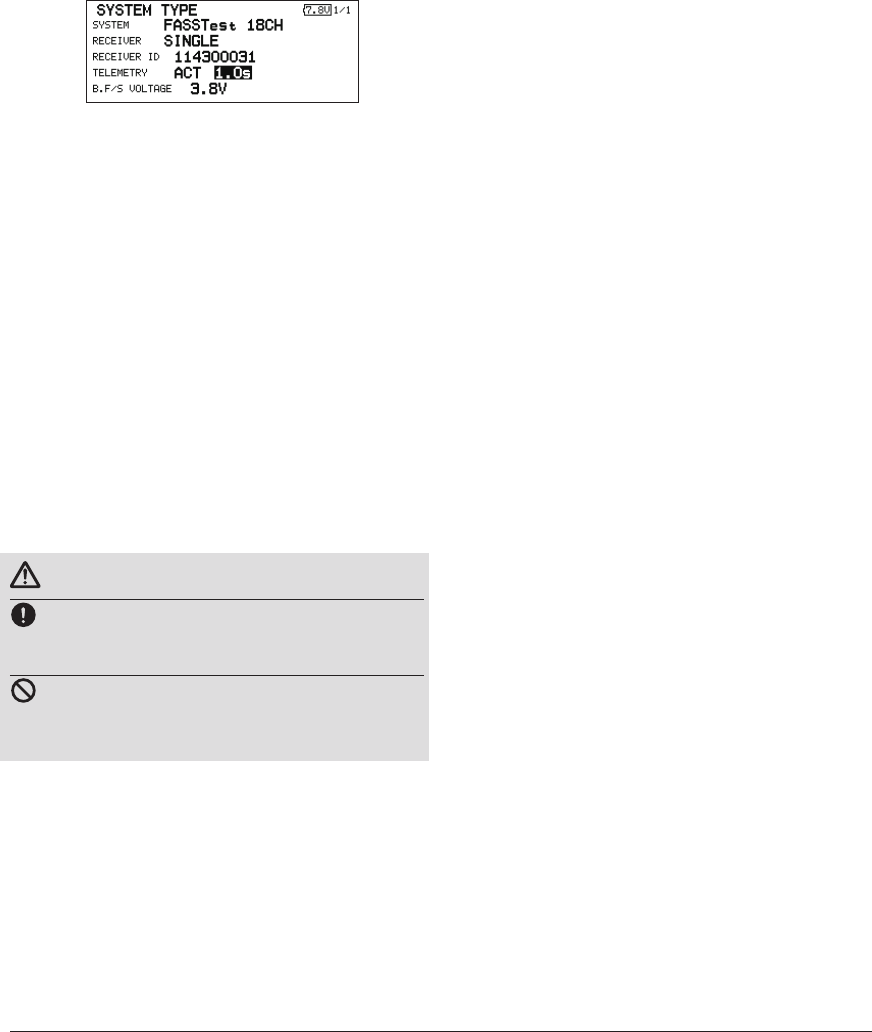
<Basic Operation>
10. When a telemetry function is enabled,
the receiving interval (down-link interval) of
sensor data can be changed. If a DL interval
is increased, the response of the sensor data
display becomes slower, but stick response
will improve.
Initial value: 1.0s
Adjustment range: 0.1s~2.0s
* If there are many FASSTest systems turned on around your
receiver, it might not link to your transmitter. In this case,
even if the receiver's LED stays solid green, unfortunately
the receiver might have established a link to one of other
transmitters. This is very dangerous if you do not notice
this situation. In order to avoid the problem, we strongly
recommend you to doublecheck whether your receiver is
really under control by your transmitter by giving the stick
input and then checking the servo response.
*Do not perform the linking operation when the drive motor
is connected or the engine is running.
*When you use two receivers, please be sure to setup a
"primary" and "secondary" in the "dual" mode.
*Telemetry function cannot be used for the 2nd receiver.
* You must link one receiver at a time. If both power
supplies to the receivers are switched on simultaneously,
data is received incorrectly by the transmitter.
* You cannot link three receivers.
* Link is required when a system type is changed.
* Linking is required whenever a new model is made.
WARNING
After the linking is done, please cycle receiver
power and check that the receiver to be linked
is really under the control of the transmitter.
Do not perform the linking procedure with
motor's main wire connected or with the engine
operating as it may result in serious injury.
36 <Basic Operation>
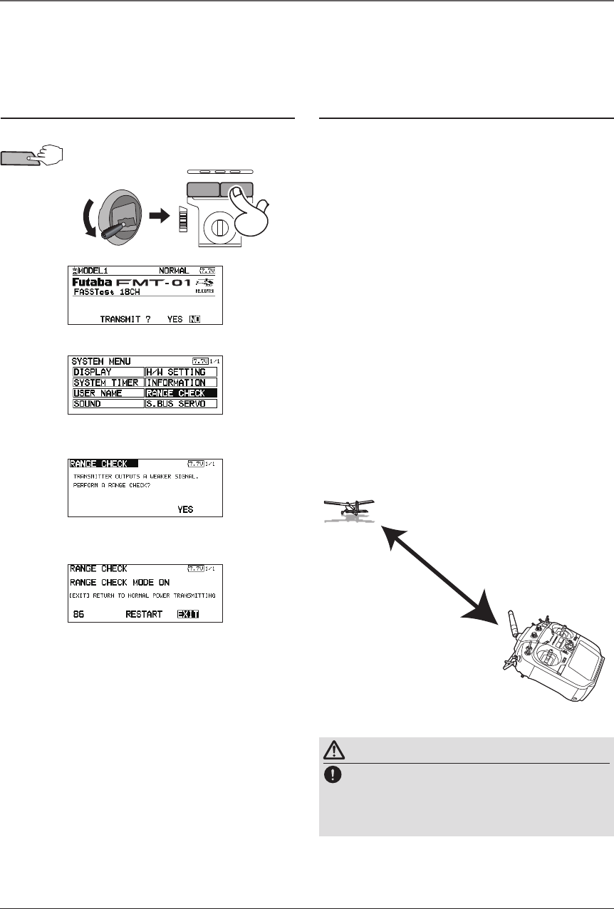
Range Testing Your R/C System
It is extremely important to range check your models prior to each ying session. This enables you to
ensure that everything is functioning as it should and to obtain maximum enjoyment from your time ying.
The T18SZ transmitter incorporates a system that reduces its power output and allows you to perform such
a range check.
Range check mode
During this mode, the RF power output is reduced
so the range test can be performed. In addition, when
this mode is activated the right LED on the front of the
transmitter starts blinking and the transmitter gives users
a warning with a beeping sound every 3 seconds.
The "Range check mode" continues for 90 seconds
and after that the power will return to the normal level.
To exit the "Range check mode" before the 90 seconds,
select the "EXIT" at the screen and touch the RTN button
again. This mode is available one time only so if you
need to re-use this function the transmitter power must
be cycled. NEVER start flying when the "Range check
mode" is active.
Should you require additional time to perform a range
check, highlight Restart before your time expires and
press the RTN button one time.
Range check procedure
1. With the "Range check mode" on, walk
away from the model while simultaneously
operating the controls. Have an assistant
stand by the model to confirm that all
controls are completely and correctly
operational. You should be able to walk
approximately 30-50 paces from the model
without losing control.
2. If everything operates correctly, return to
the model. Set the transmitter in a safe, yet
accessible, location so it will be within reach
after starting the engine or motor. Be certain
the throttle stick is in the low throttle position,
then start the engine or motor. Perform
another range check with your assistant
holding the aircraft with the engine running
at various speeds. If the servos jitter or move
inadvertently, there may be a problem. We
would strongly suggest you do not y until the
source of the difculty has been determined.
Look for loose servo connections or binding
pushrods. Also, be certain that the battery
has been fully charged.
About 100 feet
Range check mode
Range checking on
low power.
WARNING
Do not y in the range check mode.
*Since the range of the radio waves is short, if the model
is too far from the transmitter, control will be lost and the
model will crash.
2. THR Stick Slow.
1. While pushing previously "U.menu/Mon" button.
4. Scroll to "NO" and press RTN.
5. "RANGE CHECK" is chosen from
"SYSTEM MENU" and press RTN.
6. "YES" is chosen from "RANGE
CHECK" and press RTN.
3. T18SZ Power ON.
U.menu/Mon
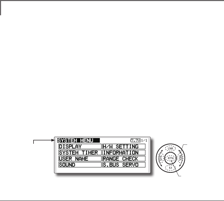
39
<Functions of System Menu>
SYSTEM MENU
System Menu functions table
[DISPLAY]: LCD contrast and back light adjustment.
[SYSTEM TIMER]: Resets the accumulated timer for each model.
[USER NAME]: User name registration.
[SOUND]: Various volume control and low battery setting.
[H/W SETTING]: H/W reverse, stick mode, stick calibration, and switch position.
[INFORMATION]: Displays the program version, SD card information, and language selection.
[RANGE CHECK]: A transmitting output is lowered and the check before a ight is carried out.
[S.BUS SERVO]: S.BUS servo setting.
The System Menu sets up functions of the
transmitter: This does not set up any model data.
● Select [SYSTEM] at the home screen and call
the system menu shown below by touching
the RTN button.
● Scrolling the touch sensor to select the
function you want to set and call the setup
screen by touching the RTN button.
● Select the function name
and return to the System
menu by touching the
RTN button or pushing the
Home/Exit button.
<SensorTouch™>
●Access setup screen
Scrolling
● Moving cursor
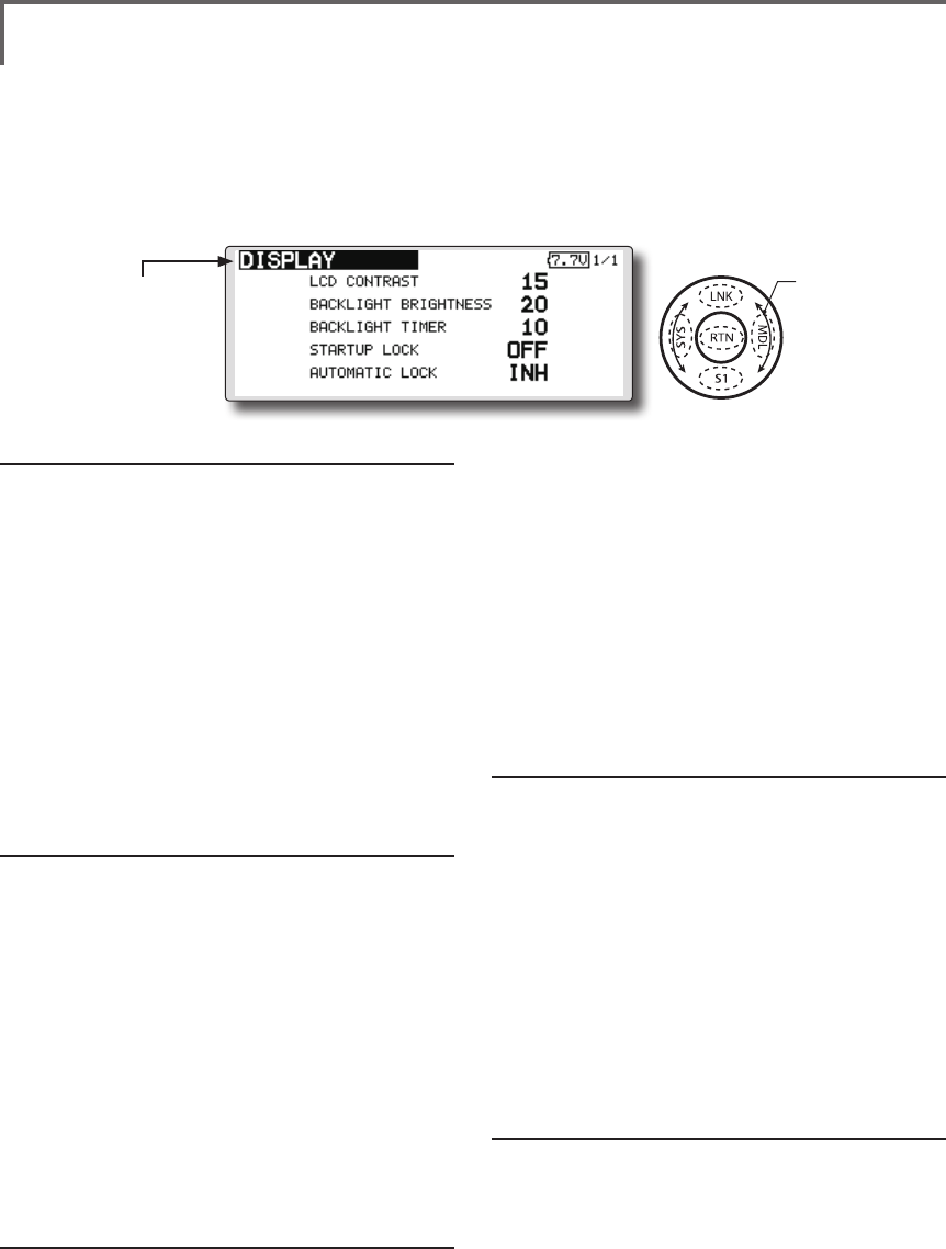
40 <Functions of System Menu>
● Select the function name
and return to the System
menu by touching the
RTN button or pushing the
Home/Exit button.
<SensorTouch™>
LCD contrast adjustment
1. Scrolling the touch sensor to select "LCD
CONTRAST" and touch the RTN button to
switch to the data input mode and adjust
the contrast by turning the touch sensor to
the left and right.
Setting range: (Lighter) 0 to 30 (Darker)
Initial value: 15
Touch the RTN button to end adjustment and
return to the cursol move mode.
*Adjust to the contrast while watching the screen display.
*When you want to reset the contrast to the initial state,
select "LCD CONTRAST" and touch the RTN button for 1
second.
Backlight brightness adjustment
1. Scrolling the touch sensor to select
"BACKLIGHT BRIGHTNESS" and touch the RTN
button to switch to the data input mode
and adjust the contrast by turning the touch
sensor to the left and right.
Setting range: (Darker) 0 to 30 (Lighter)
Initial value: 10
Touch the RTN button to end adjustment and
return to the cursol move mode.
*Adjust to the brightness while watching the screen display.
*When you want to reset the contrast to the initial state, select
"BACKLIGHT BRIGHTNESS" and touch the RTN button
for 1 second.
Back-light off-timer
1. Select "Back-light timer" and touch the RTN
button to switch to the data input mode and
adjust the back-light off-timer by scrolling the
touch sensor.
"OFF TIMER": Adjust the time when the back-
DISPLAY LCD contrast adjustment and automatic key lock
The following LCD screen adjustments and auto
power off setting are possible:
● Backlighting brightness adjustment
● Backlighting off timer adjustment
● Automatic key lock setup
light turns off after operating the touch
sensor.
Setting range: 10 to 240 sec (each 10 sec),
OFF (always on)
Initial value: 10 sec
*When you want to reset the value to the initial state, touch
the RTN button for one second.
2. Touch the RTN button to end adjustment and
return to the cursor mode.
*If the back light is on for a long time, consumption current
will increase.
Start lock
Auto Lock functions automatically when the
model changes or power is turned on.
*To temporarily allow access to the T18SZ programming
press and hold the S1 button for one second. Please note,
the Auto Lock function timer will resume immediately once
again.
1. Select "STARTUP LOCK" and touch the RTN
button to switch to the data input mode and
adjust the ON or OFF by scrolling the touch
sensor.
Setting range: ON or OFF
Initial value: OFF
Automatic lock
Auto Lock functions automatically when there is
no operation from the HOME screen display for a
chosen number of seconds.
1. Scrolling the touch sensor to select
"AUTOMATIC LOCK" and touch the RTN
button to switch to the data input mode and
adjust the time by turning the touch sensor to
the left and right.
Setting range: INH, 0 to 120 (s)
Initial value: INH
● Select [DISPLAY] at the system menu and call the setup
screen shown below by touching the RTN button.
Scrolling
● Moving cursor
● Selecting mode
● Adjusting value
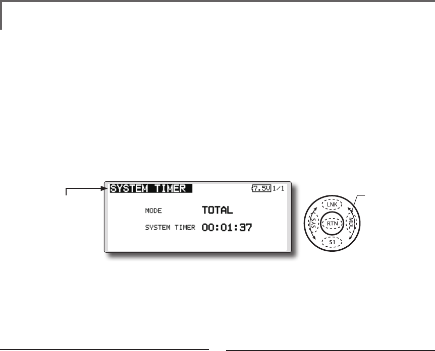
41
<Functions of System Menu>
● Select the function name
and return to the System
menu by touching the
RTN button or pushing the
Home/Exit button.
<SensorTouch™>
Timer selection
1.Move the cursor to the [MODE] item and
touch the RTN button to switch to the data
input mode.
Select the mode by scrolling the touch sensor
and touch the RTN button.
TOTAL: Displays the total timer on the home
screen.
MODEL timer: Displays the model timer on
the home screen.
SYSTEM TIMER Resets the accumulated timer.
This function resets the system timer displayed
on the home screen.
● T18SZ has two type system timers.
TOTAL timer: Displays the total accumulated
time on the transmitter from the last time the
timer was reset.
MODEL timer: Displays the total accumulated
time on each model from the last time the
timer was reset.
● System timer displayed on the home screen
can be selected.
● Select [SYSTEM TIMER] at the system menu and
call the setup screen shown below by touching
the RTN button.
Timer reset
1.Move the cursor to the [SYSTEM TIMER] item
and reset the timer to "00:00:00" by touching
the RTN button for 1 second. After reset, the
timer restarts from "00:00:00".
Scrolling
● Moving cursor
● Selecting mode
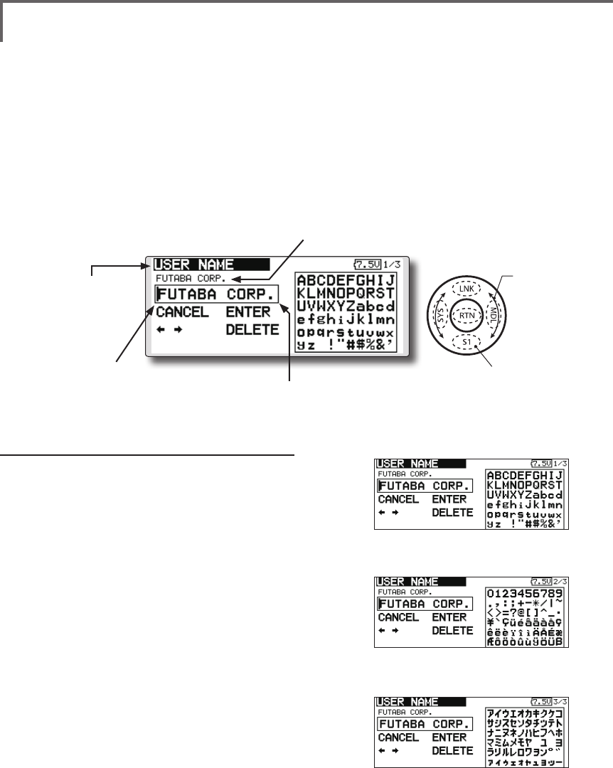
42 <Functions of System Menu>
● Select the function name
and return to the System
menu by touching the
RTN button or pushing the
Home/Exit button.
<SensorTouch™>
USER NAME User name registration
This function registers the T18SZ user name.
*A name of up to 12 characters can be entered as the user
name. (Space is also counted as 1 character.)
User name registration
1. Change the user name as described below:
[Moving cursor in input box]
Select [←] or [→], and touch the RTN button.
[Deleting a character]
When [DELETE] is selected and the RTN button
is touched, the character immediately after
the cursor is deleted.
[Adding a character]
When a candidate character is selected
from the character list and the RTN button
is touched, that character is added at the
position immediately after the cursor.
*A name of up to 12 characters long can be entered as the
user name. (A space is also counted as 1 character.)
2. At the end of input, select [ENTER] and touch
the RTN button. (To terminate input and
return to the original state, select [CANCEL]
and touch the RTN button.)
(Character list 1/3)
(Character list 2/3)
(Character list 3/3)
● Select [USER NAME] at the system menu and call
the setup screen shown below by touching the
RTN button.
● Push the S1 button to
call next page.
Current user name
Input box
Cursor (blink)
Scrolling
● Moving cursor
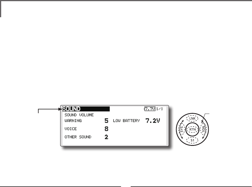
43
<Functions of System Menu>
● Select the function name
and return to the System
menu by touching the
RTN button or pushing the
Home/Exit button.
<SensorTouch™>
3 independent sound volumes: "WARNING",
"VOICE" and others, are available.
"LOW BATTERY" adjusts low battery alarm
voltage to match a battery.
● Select [SOUND] at the system menu and access
the setup screen shown below by touching the
RTN button.
● LOW BATTERY : 6.8V~7.6V
Sound volume operation
1. Move the cursor to the [WARNING][VOICE]
or [OTHER SOUND] item and touch the RTN
button to switch to the data input mode.
2. Select the volume by scrolling the touch
sensor.
*The display blinks.
3.Touch the RTN button.
Low battery voltage operation
1. Move the cursor to the [LOW BATTERY] item
and touch the RTN button to voltage to the
data input mode.
2. Select the voltage by scrolling the touch
sensor. (6.8V-7.6V)
*The display blinks.
3.Touch the RTN button.
SOUND Turns off the buzzer.
Scrolling
● Moving cursor
● Adjusting value