Futaba T18SZ-24G Radio Control User Manual Part III
Futaba Corporation Radio Control Part III
Futaba >
Contents
- 1. User Manual-Part I
- 2. User Manual-Part II
- 3. User Manual-Part III
User Manual-Part III
100 <Functions of Linkage Menu>
● Select the function name
and return to the Linkage
menu by touching the
RTN button or pushing the
Home/Exit button.
<SensorTouch™>
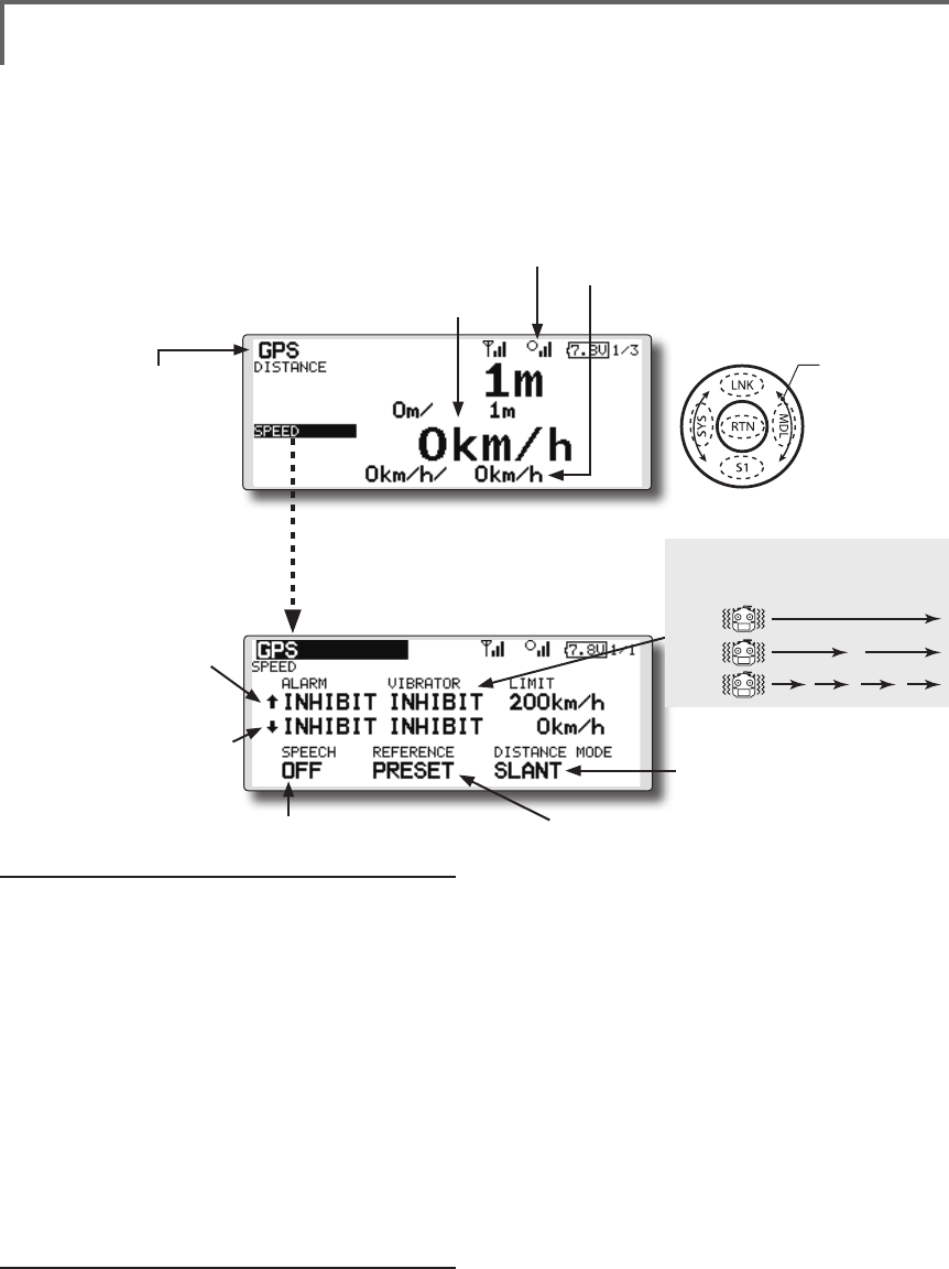
TELEMETRY : GPS [SPEED] Displaying data from the speed
The speed screen displays and sets the speed data from an
SBS-01G (GPS sensor) sold separately.
The speed of the aircraft during ight can be displayed.
After flight, the maximum speed during flight can be
viewed. Because this speed is based on position data from
a GPS satellite, the ground speed is displayed instead of
air speed. Consequently, with a head wind, the displayed
speed decreases and with a tail wind, the displayed speed
increases.
*The GPS sensor is necessary, and is sold separately. Mount and
connect the sensor in accordance with the sensor instruction manual.
*It cannot be used in FASST mode and S-FHSS mode.
*Only receiver voltage and EXT voltage can be used in
FASSTest12CH mode.
*The FASSTest18CH mode can use all the telemetry functions.
*A GPS sensor must be installed in the aircraft.
●This indicates the receiving accuracy
from a GPS Satellite. When three bars
are displayed, the GPS is ready for use.
● Select [GPS] in the TELEMETRY screen and
access the setup screen shown below by
touching the RTN button.
Scrolling
● Moving cursor
● Speed
● ↓ A downward arrow
indicates the alarm will
sound when the speed
reaches below your set
value.
● ↑ An upward arrow
indicates the alarm will
sound when the speed
reaches above your set
value.
●Select [SPEED](small font display) in
the TEMPERATURE screen and access
the setup screen shown below by
touching the RTN button.
● The maximum and the minimum when powering ON
are shown. It will be preset, if a cursor is moved to this
place and the RTN button is pushed for 1 second.
●The ON/OFF switch of
SPEECH is chosen.
●It links with the "DISTACE"
display.
●Pushing [PRESET] sets the current aircraft
position as the starting point.
Alarm setting when speed increases
1. Move the cursor to the ↑ALARM item, and it
chooses from BUZZER, VOICE, INHIBIT, and pushes
RTN.
2. When not operating vibrator, it is "VIBRATOR"
to INHIBIT. TYPE1-3 will be chosen if it is made to
operate.
3. Move the cursor to the LIMIT [km/h] item and touch
the RTN button to switch to the data input mode.
4. Ajust the rate by scrolling the touch sensor.
Initial value: 200km/h
Adjustment range 0km/h~500km/h
(↑LIMIT ≧ ↓LIMIT)
*When the RTN button is touched for one second, the rate is
reset to the initial value.
5. Touch the RTN button. (To terminate the input and
return to the original state, touch the Home/Exit
button.)
Alarm setting when speed decreases
1. Move the cursor to the ↓ALARM item, and it
chooses from BUZZER, VOICE, INHIBIT, and pushes
RTN.
2. When not operating vibrator, it is "VIBRATOR"
to INHIBIT. TYPE1-3 will be chosen if it is made to
operate.
3. Move the cursor to the LIMIT [km/h] item and touch
the RTN button to switch to the data input mode.
4. Ajust the rate by scrolling the touch sensor.
Initial value: 0km/h
Adjustment range 0km/h~500km/h
(↑LIMIT ≧ ↓LIMIT)
*When the RTN button is touched for one second, the rate is
reset to the initial value.
5. Touch the RTN button. (To terminate the input and
return to the original state, touch the Home/Exit
button.)
*Speed alarm precaution
Since the GPS speed sensor displays the ground speed, it
cannot be used as a stall alarm. For example, an aircraft that
stalls at 50km/h will stall if the tailwind is 5km/h or greater
even through 55km/h is displayed by ground speed. In
addition, with an aircraft that will disintegrate in midight at
400km/h at an over-speed alarm, when the headwind reaches
30km/h the airplane will disintegrate in midair due to over
speeding even at a ground speed of 370km/h.
TYPE 1
TYPE 2
TYPE 3
"VIBRATOR" type
If the following types are selected, the
transmitter will vibrate during the warning.
101
<Functions of Linkage Menu>
● Select the function name
and return to the Linkage
menu by touching the
RTN button or pushing the
Home/Exit button.
<SensorTouch™>
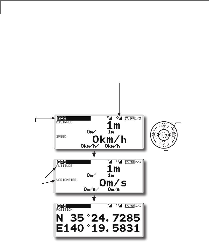
TELEMETRY : GPS [ALTITUDE, VARIOMETER, POSITION]
The altitude, variometer, position screen displays
and sets the data from an SBS-01G (GPS sensor)
sold separately.
*The GPS sensor is necessary, and is sold separately. Mount
and connect the sensor in accordance with the sensor
instruction manual.
*It cannot be used in FASST mode and S-FHSS mode.
*Only receiver voltage and EXT voltage can be used in
FASSTest12CH mode.
*The FASSTest18CH mode can use all the telemetry functions.
*A GPS sensor must be installed in the aircraft.
●This indicates the receiving accuracy
from a GPS Satellite. When three bars
are displayed, the GPS is ready for use.
● Select [GPS] in the TELEMETRY screen and
access the setup screen shown below by
touching the RTN button.
● Push S1 button to advance to next page.
● Refer to the former
page for a setup
about ALTITUDE
and VARIOMETER.
● Push S1 button to advance to next page.
● The position of the present model is displayed.
Scrolling
● Moving cursor
● To next page
102 <Functions of Linkage Menu>
● Select the function name
and return to the Linkage
menu by touching the
RTN button or pushing the
Home/Exit button.
<SensorTouch™>
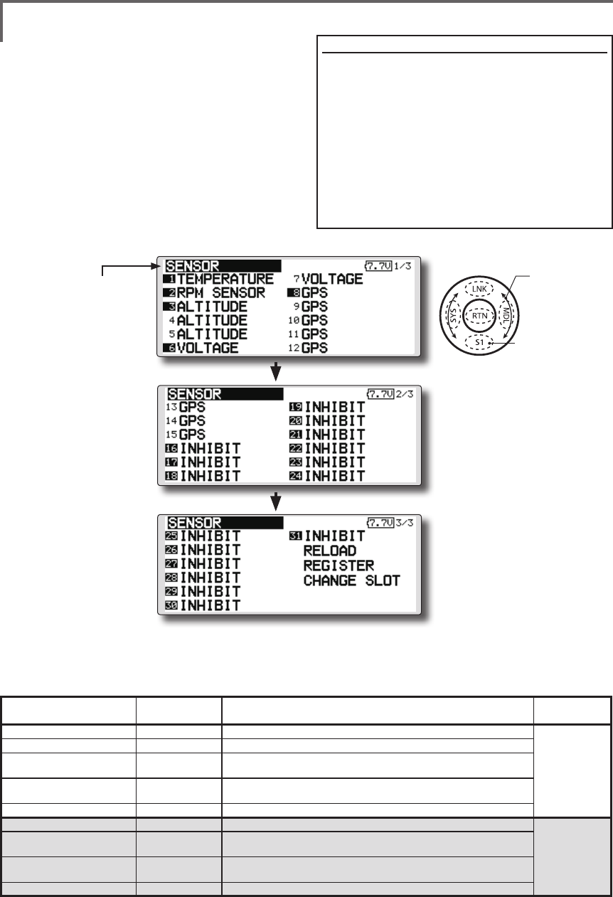
SENSOR Various telemetry sensors setting
This screen registers the telemetry sensors used
with the transmitter. When only one of a certain
type of sensor is used, this setting is unnecessary
and the sensor can be used by simply connecting it
to the S.BUS2 port of the transmitter.
When using 2 or more of the same kind of
sensor, they must be registered here.
● Select [SENSOR] in the Linkage menu and
access the setup screen shown below by
touching the RTN button.
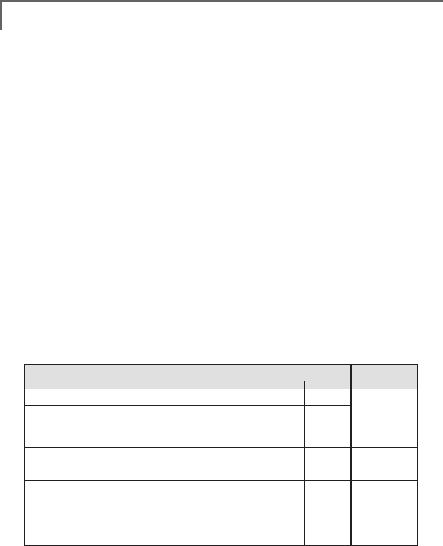
● As shown in the table below, an altimeter requires 3 contiguous slots and a GPS sensor
requires 8 contiguous slots. In addition, since the GPS (SBS-01G) start slots are 8, 16, and 24.
<Assignable slot >*Altimeter, GPS, and other sensors that display a large amount of data require multiple slots.
*Depending on the type of sensor, the slot numbers that can be allocated may be limited.
[What is a slot?]
Servos are classified by CH, but sensors are
classified in units called “slot”. There are slots
from No. 1 to No. 31.
Altitude sensors, GPS sensors and other data
sensor units may use multiple slots.
Using a sensor which uses two or more slots,
the required number of slots is automatically
assigned by setting up a start slot.
When 2 or more of the same kind of sensor are
used, the sensors themselves must allocate unused
slots and memorize that slot.
*3 slots of altitude sensor are used.
*8 slots of GPS sensor are used.
Sensor The required
number of slots The number which can be used as a start slot Selling area
TEMP (SBS-01T/TE) 1 slot 1 ~31
Global
RPM (SBS01RM/RO/RB) 1 slot 1 ~31
Voltage (SBS-01V) 2 slots 1,2,3,4,5,6,8,9,10,11,12,13,14,16,17,18,19,20,21,22,24,2
5,26,27,28,29,30
Altitude (SBS-01A) 3 slots 1,2,3,4,5,8,9,10,11,12,13,16,17,18,19,20,21,24,25,26,27,
28,29
GPS (SBS-01G) 8 slots 8,16,24
TEMP125-F1713 1 slot 1 ~31
Europe
VARIO-F1712 2 slots 1,2,3,4,5,6,8,9,10,11,12,13,14,16,17,18,19,20,21,22,24,2
5,26,27,28,29,30
VARIO-F1672 2 slots 1,2,3,4,5,6,8,9,10,11,12,13,14,16,17,18,19,20,21,22,24,2
5,26,27,28,29,30
GPS-F1675 8 slots 8,16,24
Scrolling
● Moving cursor
● To next page
● Push S1 button to advance to next page.
● Push S1 button to advance to next page.
103
<Functions of Linkage Menu>
● Select the function name
and return to the Linkage
menu by touching the
RTN button or pushing the
Home/Exit button.
● Select the function name
and return to the Linkage
menu by touching the
RTN button or pushing the
Home/Exit button.
● Call page 3/3 by touching the S1 button 2 times
from the [SENSOR] menu.
● Call page 3/3 by touching the S1 button 2 times
from the [SENSOR] menu.
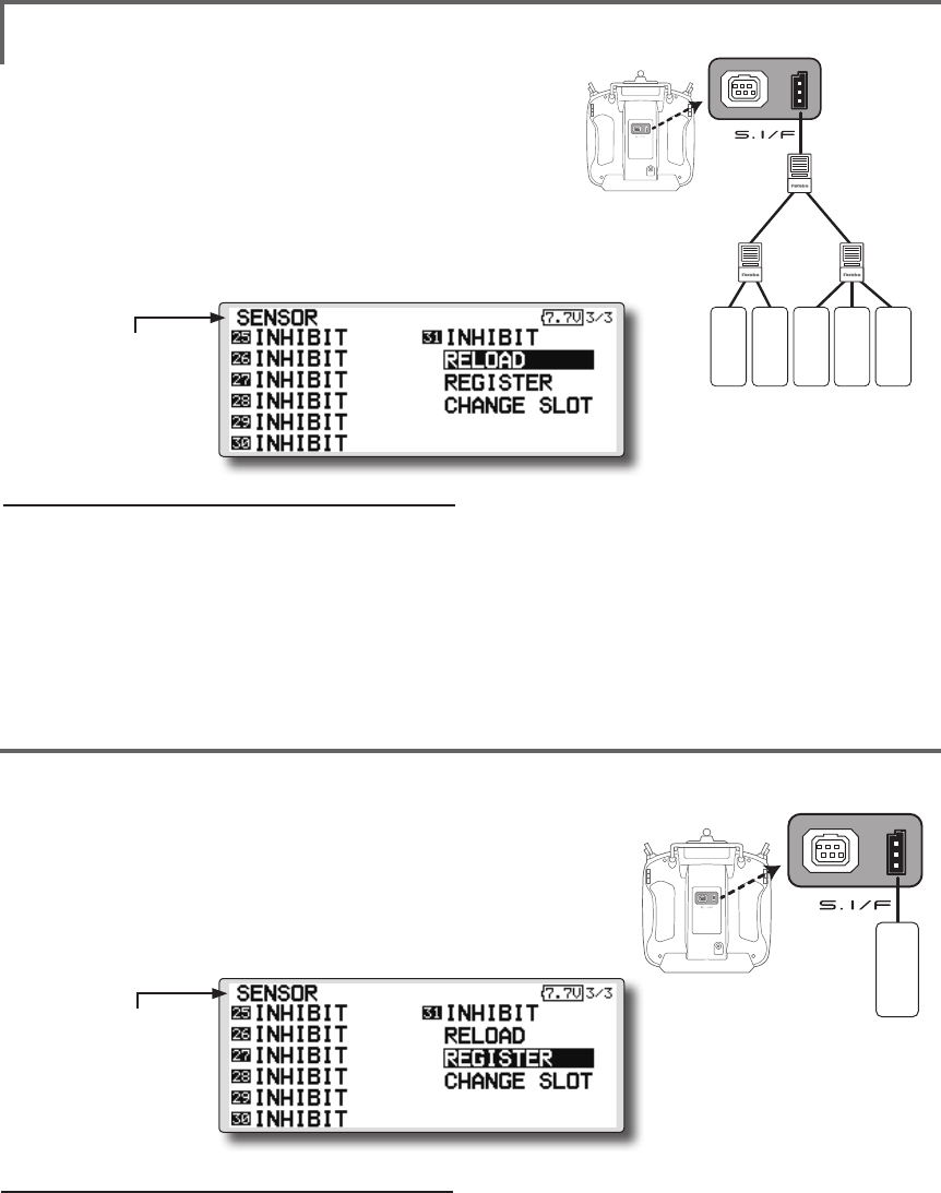
SENSOR : RELOAD
SENSOR : REGISTER
This page is set when using multiple telemetry sensors of the same type.
This page is set when using multiple telemetry sensors of the same type.
When using multiple sensors of the same type
the sensors must be registered in the transmitter.
Connect all the sensors to be used to the T18SZ as
shown in the gure at the right and register them by
the following procedure. The ID of each sensor is
registered in the transmitter.
This function registers an additional sensor.
Connect the sensor as shown in the figure at the
right and register it by the following procedure.
The sensor ID is registered in the transmitter.
T18SZ
All the sensors to be used are connected.
SENSOR
SENSOR
3-way hub
or Y-harnesses
SENSOR
SENSOR
SENSOR
T18SZ
SENSOR
Reading all the sensors to be used
1. Connect all the sensors to be used to the
T18SZ through a hub as shown in the figure
above.
2. Move the cursor to “RELORD” on page 3/3 of
the [SENSOR] screen.
3. Touch the RTN button.
All the sensors are registered and can be
used.
Additional sensor registration
1. Connect the sensor to be used to the T18SZ
through a hub as shown in the gure at the
right.
2. Move the cursor to “REGISTER” on page 3/3
of the <Sensor> screen.
3. Touch the RTN button.
The sensor is registered and can be used.
*When the number of slots needed in registration is
insufcient, an error is displayed and registration cannot be
performed. Disable unused slots or perform the following
relocate.
*It is not necessary to carry out
multiple connection of the
battery like a T18MZ/T14SG.
(It will damage, if it connects.)
*It is not necessary to carry out
multiple connection of the
battery like a T18MZ/T14SG.
(It will damage, if it connects.)
104 <Functions of Linkage Menu>
● Select the function name
and return to the Linkage
menu by touching the
RTN button or pushing the
Home/Exit button.
● Call page 3/3 by touching the S1 button 2 times
from the [SENSOR] menu.
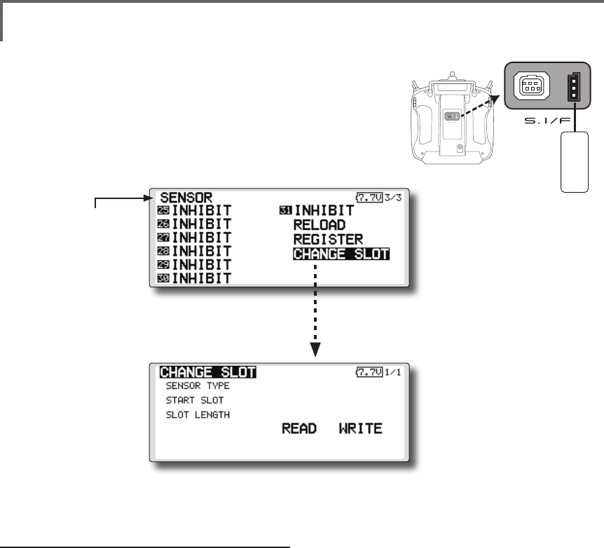
This procedure changes the slot No. of one
registered sensor.
Sensor slot change
1. Connect the sensor to be changed to the
T18SZ through a hub as shown in the figure
above.
2. Move the cursor to “CHANGE SLOT” on page
3/3 of the <Sensor> screen.
3. Touch the RTN button. A sensor details screen
appears.
4. Move the cursor to “READ” and touch the
RTN button.
5. The current start slot is displayed. Move the
cursor to the number of the start slot and
change it to the desired value.(Cannot be
set to a slot that cannot be allocated like the
table of all pages.)
6. Move the cursor to “WRITE” and touch the
RTN button.
SENSOR : CHANGE SLOT This page is set when using multiple telemetry sensors
of the same type.
● Select [CHANGE SLOT] in the SENSOR
screen and access the setup screen
shown below by touching the RTN button.
*It is not necessary to carry out
multiple connection of the
battery like a T18MZ/T14SG.
(It will damage, if it connects.)
T18SZ
SENSOR
105
<Functions of Linkage Menu>
● Select the function name
and return to the Linkage
menu by touching the
RTN button or pushing the
Home/Exit button.
<SensorTouch™>
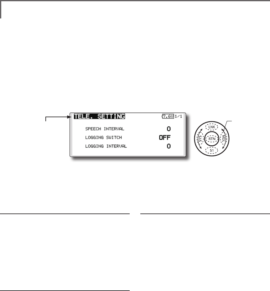
TELE. SETTING Speech interval set , data logging of telemetry.
The set of the speech interval of teremetry data,
and a switch setup for carrying out logging of the
teremetry data to SD card and a setup of a logging
interval are carried out.
teremetry data can be checked with PC after a
ight.
*The software which displays the logging data of SD card on
PC has not been put on the market yet.
Speech interval setting
1. Select the Linkage Menu [TELE. SETTING] and
touch the RTN button.
2. The TELE. SETTING setup screen is displayed.
3. Select numerical value beside[SPEECH
INTERVAL] and touch the RTN button.
4. Ajust the time by scrolling the touch sensor.
Initial value: 0
Adjustment range 0~30
5. Touch the RTN button.
Logging switch setting
1. Select the Linkage Menu [TELE. SETTING] and
touch the RTN button.
2. The TELE. SETTING setup screen is displayed.
3. Select [OFF] beside[LOGGING SWITCH] and
touch the RTN button.
4. Move the cursor to the [SWITCH] item and
call the switch setup screen by touching the
RTN button and select the switch and ON
direction.
(For a detailed description of the setting method, see [Switch
Setting Method] at the end of this manual.)
Logging interval setting
1. Select the Linkage Menu [TELE. SETTING] and
touch the RTN button.
2. The TELE. SETTING setup screen is displayed.
3. Select numerical value beside[LOGGING
INTERVAL] and touch the RTN button.
4. Ajust the time by scrolling the touch sensor.
Initial value: 0
Adjustment range 0~100
5. Touch the RTN button.
● Select [TELE. SETTING] at the linkage menu and call
the setup screen shown below by touching the
RTN button.
Scrolling
● Moving cursor
● Selecting mode
● Adjusting value
106 <Functions of Linkage Menu>
● Select the function name
and return to the Linkage
menu by touching the
RTN button or pushing the
Home/Exit button.
<SensorTouch™>
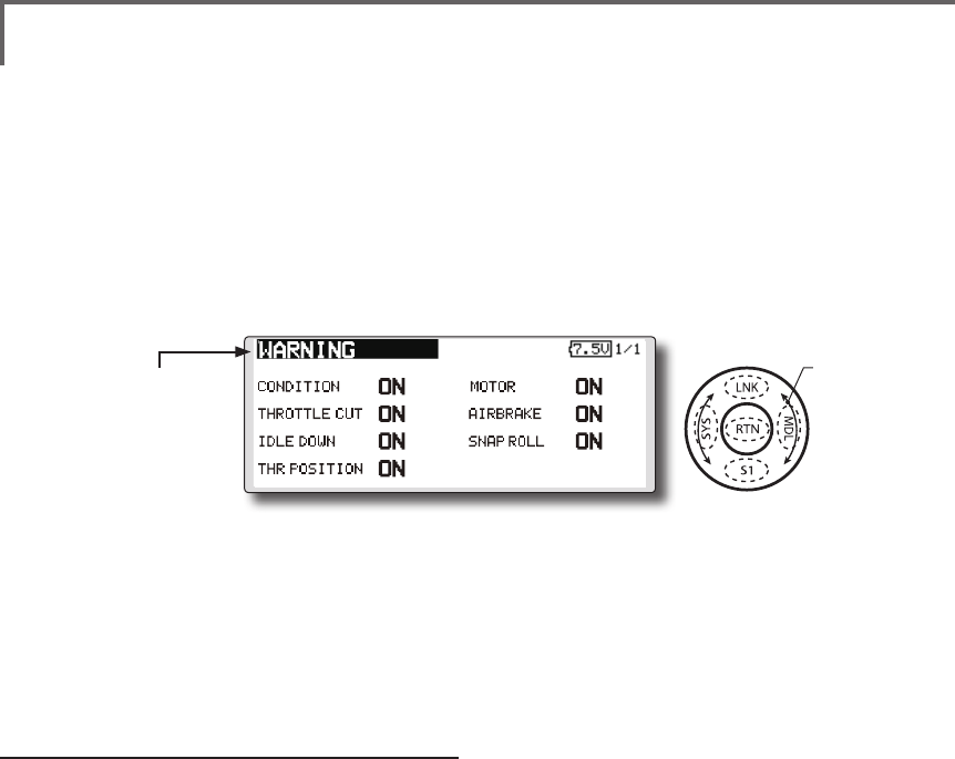
WARNING Mixing warning normal reset
The warning display at power ON can be turned
ON/OFF for each function. Use by setting functions
which may be dangerous if operated at power ON
to ON. Initial setting is all ON.
Warning ON/OFF setting
1. The settings can be changed individually.
When set to [OFF], a warning is not displayed
at power ON.
● Select [WARNING] at the linkage menu and call
the setup screen shown below by touch the RTN
button.
Scrolling
● Moving cursor
● Selecting mode
107
<Functions of Linkage Menu>
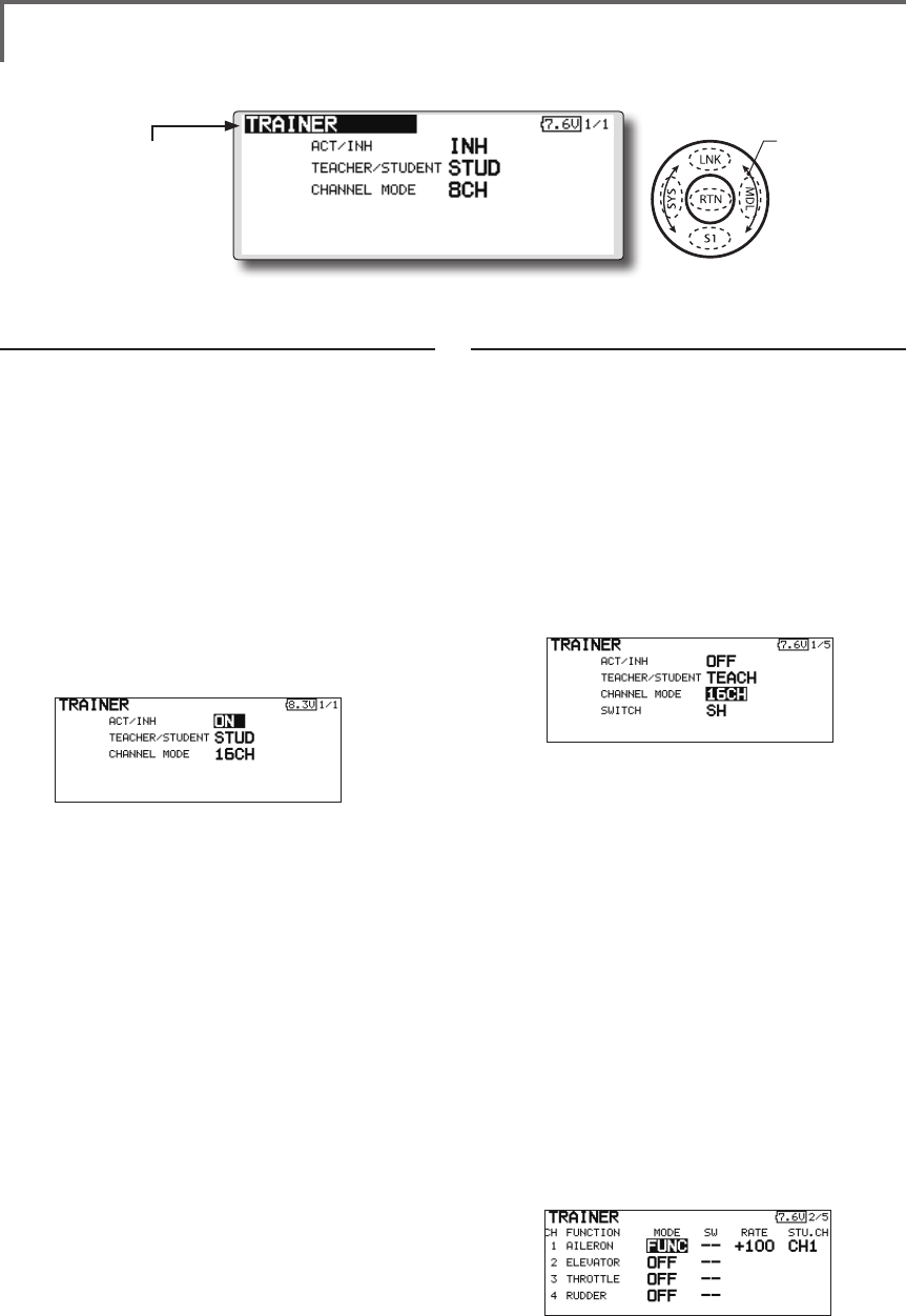
TRAINER Trainer system starting and setting
T18SZ trainer system makes it possible for the
instructor to chose which channels and operation
modes that can be used in the students transmitter.
The function and rate of each channel can be
set, the training method can also be matched to
the student's skill level. Two transmitters must be
connected by an optional Trainer Cord, and the
Instructors’ transmitter should be programmed for
trainer operation, as described below.
When the Instructor activates the trainer switch,
the student has control of the aircraft (if MIX/
FUNC/NORM mode is turned on, the Instructor
can make corrections while the student has control).
When the switch is released the Instructor regains
control. This is very useful if the student gets the
aircraft into an undesirable situation.
● Setting data are stored to model data.
● Student rate can be adjusted at MIX/FUNC/
NORM mode.
● Activated student channels can be selected
by switches.
NOTE: This trainer system can be used in the
following manner;
1. With the T18SZ transmitter and a conventional
transmitter, if the channel order is different,
it is necessary to match the channel order
before using this function.
You can select the channel of input data
from student's transmitter in the "FUNC" or
"MIX" mode.
2. When the T18SZ is used as the instructor’s
transmitter, set the modulation mode of the
student’s transmitter to PPM.
If being used as the student, T18SZ can be
connected to the instructor's transmitter which
the PPM mode as the student's modulation
mode is required. T18SZ always sends PPM
mode signal from the trainer jack.
(In the case of student's transmitters other than
2.4 GHz)
3. Be sure that all channels work correctly in
both transmitters before ying.
Corresponding types of transmitters and trainer mode settings:
Types of transmitters Instructor's transmitter settings Student's transmitter settings
System Type Trainer setting System Type Trainer setting Trainer Cords
Instructor Student Mod. mode CH mode Mod. mode CH mode Mod. mode
T18SZ,FX-32
T14SG,T18MZ
T18SZ,FX-32
T14SG,T18MZ Arbitrary 16CH Arbitrary 16CH -
T12FG (FUTM4405)
and 9C (FUTM4415)
Trainer Cords
T18SZ
T14MZ, FX-40,
T12Z, T12FG,
FX-30
Arbitrary 12CH PCM-G3
2.4G 12CH PPM
T18SZ T8FG, FX-20 Arbitrary 12CH FASST-MLT2 - -
8CH FASST-MULT
T18SZ
T10C, T9C,
T7C,T6EX,
T4EX
Arbitrary 8CH PPM - - T12FG (FUTM4405)
T18SZ T10CG,T7C Arbitrary 8CH Arbitrary - - T12FG (FUTM4405)
T18SZ T8J,T6J Arbitrary 8CH Arbitrary - -
T12FG (FUTM4405)
and 9C (FUTM4415)
Trainer Cords
T14MZ, FX-40,
T12Z, T12FG,
FX-30
T18SZ Arbitrary 12CH Arbitrary 12CH -
T8FG, FX-20 T18SZ Arbitrary 12CH Arbitrary 12CH -
T10C, T10CG,
T9C, T7C,
T7C,T8J
T18SZ Arbitrary -Arbitrary 8CH -
108 <Functions of Linkage Menu>
● Select the function name
and return to the Linkage
menu by touching the
RTN button or pushing the
Home/Exit button.
<SensorTouch™>
When using at the teacher side
1. Select the mode.
*When changing the mode, use the touch sensor to move
to the item you want to change and touch the RTN button
to switch to the data input mode and change the mode by
turning the touch sensor to the left or right. The display
blinks. Touch the RTN button to change the mode.
"TEACHER/STUDENT": Select [TEACH].
"ACT/INH": Enable operation by changing to
[OFF] or [ON].
"16/12/8 CHANNEL": When the student uses
the T18SZ (including the T18MZ, T14SG)select
[16CH]. Otherwise select [12CH]or[8CH].
2. Select the trainer switch.
*When setting or changing the switch, use the touch sensor
to move to the "SWITCH" item, call the switch setup screen
by touching the RTN button and set the desired switch and
ON/OFF direction.
(See "Switch selection method" at the end of
this manual for selection method details.)
*The switch mode can also be selected when setting the
ON position on the switch setup screen. When [NORM] is
selected, normal ON/OFF operation is performed. When
[ALTERNATE] is selected, the trainer function is alternately
turned on and off each time the switch is operated. This
allows alternate ON/OFF switching even when a momentary
switch (SH) is used.
Note: The trainer function won’t be turned
on unless the Instructor's transmitter receives
signals from the student's transmitter. Be
sure to confirm this after connecting your
trainer cable.
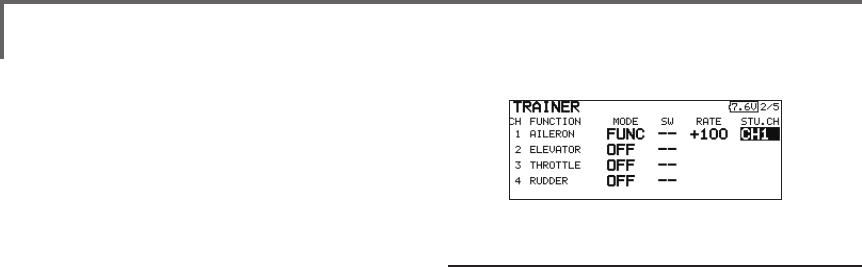
3. Select the operating mode for each channel.
● Select [TRAINER] at the system menu and call the
setup screen shown below by touching the RTN
button.
When using at the student side
1. Select the mode.
*When changing the mode, use the touch sensor to move
to the item you want to change and touch the RTN button
to switch to the data input mode and change the mode by
turning the touch sensor to the left or right. The display
blinks. Touch the RTN button to change the mode.
"TEACHER/STUDENT": Select [STUD] (student).
"ACT/INH": Enable operation by changing to
[ON].
"16/12/8 CH": When the student uses the
T18SZ,T14SG, T18MZ, select [16CH]. When the
student uses the T14MZ, T12Z, T12FG or FX-40,
select [12CH]. Otherwise select [8CH].
Note: In "student mode", only the teacher
side can turn on and off the power to the
student's transmitter. Keep the power switch
always at off position.
Scrolling
● Moving cursor
● Selecting mode
109
<Functions of Linkage Menu>
*Use the touch sensor scrolling to move the cursor to the
"MODE" item of the channel you want to change and touch
the RTN button to switch to the data input mode and change
the mode by turning the touch sensor to the left or right. The
display blinks. Touch the RTN button to change the mode.
"NORM": The model is controlled by signals
from the student transmitter.
"MIX" mode: The model is controlled by
signals from the teacher and student
transmitters. (Reset the student's model data
to the default condition.)
"FUNC" mode (function mode):
The model is controlled by signals from
the student transmitter with the teacher
AFR setting. (Reset the student's model data
to the default condition.)
"OFF": Only the teacher side operates.
*The setting above allows setting of the servo throw relative
to the amount of student side operation when [MIX] or
[FUNC] was selected.
When changing the rate, use the touch
sensor scrolling to move the cursor to the
[RATE] item of the channel you want to
change and use the touch sensor to adjust
the rate.
Setting range: -100~+100
Initial value: +100
Touch the RTN button to end adjustment and
return to the cursor move mode.
*When the RTN button is touched for 1 second, the rate is
reset to the initial value.
3. Set the switch of each channel.
*When setting the switch at each channel, use the touch
sensor to move to the "SW" item of the channel you want
to change, call the switch setup screen by touching the RTN
button, and select the switch.
"--" : Always ON.
"SA"~"SH": The switch which enables student
side operation can be selected. (See "Switch
selection method" at the end of this manual
for selection method details.)
Trainer student channel setting function
Which channel of the signal from the student's
transmitter can be fetched as the instructor
functions input signal when "FUNC" or "MIX" was
set as the trainer function instructor's transmitter
mode setting can be set. This makes trainer
connection easy even when the instructor side and
student side channel assignment is different.
*When the instructor's transmitter mode is set to "NORM",
the signal of the same channel of the student's transmitter is
output as is.(The same as before.)
110 <Functions of Linkage Menu>
● Select the function name
and return to the Linkage
menu by touching the
RTN button or pushing the
Home/Exit button.
<SensorTouch™>
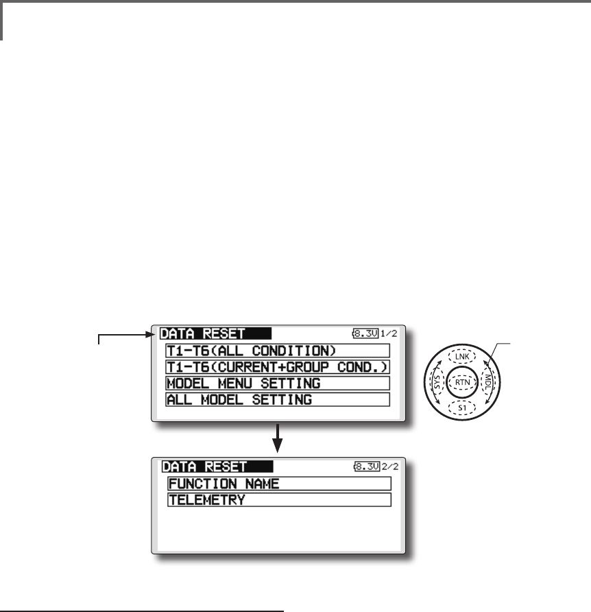
DATA RESET Model memory setting data reset. (by item)
This function is designed to allow you to reset
selected portions or all of the settings saved in
the active model memory. You may individually
choose to reset the following sets of data;
T1~T6:
Reset the digital trim setting.
*All the conditions, or the condition currently being displayed
(the entire group for group setting), can be selected.
*The trim step amount and trim rate are not reset.
Data resetting method
1. Move the cursor to the item you want to
reset and touch the RTN button.
*A conrmation message appears.
2. Execute reset by touching the RTN button
again. (Operate touch sensor or S1 button to
stop resetting.)
[T1-T6 (ALL CONDITION)]: Resets only the T1-T6
(all conditions)
[T1-T6(CURRNT+GROUP COND.)]: Resets only
the data of T1-T6 (condition in use and all the
conditions set to group mode)
[MODEL MENU SETTING]: Resets all the
functions in the model menu, except the
condition selection functions.
Model menu setting:
Resets all the functions in the Model menu
except condition select.
All model setting:
Resets all Linkage and Model menu functions
except for frequency, model select, and model type.
Function Name:
A function name is reset.
Telemetry:
Reset the telemetry setting.
[ALL MODEL SETTING]: Resets all the functions
in the linkage menu and model menu except
the frequency, model select, and model
type functions.
[FUNCTION NAME]: Resets only the function
name functions.
[TELEMETRY]: Resets only the teremetry
functions.
● Select [DATA RESET] at the linkage menu and call
the setup screen shown below by touching the
RTN button.
Scrolling
● Moving cursor
● Push S1 button to advance to next page.

111
<Functions of Linkage Menu>
COND.HOLD Condition hold function
This function may be used to x the maximum
speed of the engine so that you may adjust flight
conditions when the engine is running. An alarm
indicates that the function is operating. It will
prevent the engine from racing dangerously when
adjusting the idle-up settings.
While this function is active, the throttle servo
position is fixed at the point where you operate
when the function is activated. You must deactivate
this function when you are through making
adjustments.
The system will not allow you to activate/
deactivate this function in either of the following
states:
• When any of the flight condition switches
are on.
• When the throttle stick is higher than the
1/3 point.
To activate/deactivate condition hold:
(Home screen)
1. Move the cursor to [CND HOLD].
2. Set the throttle stick lower than the 1/3 point.
3.Touch the RTN button to activate the
condition hold function.
*When this function is active, "IS ON" appears at the right of
the [CND HOLD] display at the left bottom of the screen.
(LINKAGE menu/MODEL menu)
1. Move the cursor to [COND. HOLD].
2. Set the throttle stick lower than the 1/3 point.
3.Touch the RTN button to activate the
condition hold function.
*Operation is displayed at the bottom of the menu.
Function ON: "CND HOLD IS ON" is displayed.
Function OFF: "CND HOLD IS OFF" is displayed.
112 <Model Menu (Common Functions)>
●Selectthe[MODELMENU]
andreturnto the home
screenbytouchingthe
RTNbuttonorpushingthe
Home/Exitbutton.
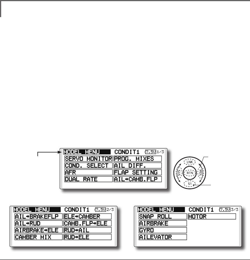
MODEL MENU (COMMON FUNCTIONS)
This section describes the AFR, program mixing,
and other functions common to all model types.
Before setting the model data, use the Model
Type function of the Linkage Menu to select the
model type matched to the fuselage. When another
model type is selected thereafter, the AFR, program
mixing, and other setting data are reset.
The functions in the Model Menu can be set for
each flight condition. When you want to use the
system by switching the settings for each condition
by switch, stick position, etc., use the Condition
Select function to add flight conditions. (Up to 8
conditions can be used)
Note:TheT18SZisdesignedsothattheairplane
andglider(includingEPglider)modeltypesare
compatiblewithaircraftofsimilartypewings.
Thissectionoutlinestherelationshipbetweenthe
functionscommontoairplanesandgliders,except
somededicatedfunctions,andmodeltype.
Thesettingitemsdependonthenumberofservos
andotherdifferencesaccordingtothewingtype
used,butrereadthem.Thesetupscreensinthe
instructionmanualaretypicalexamples.
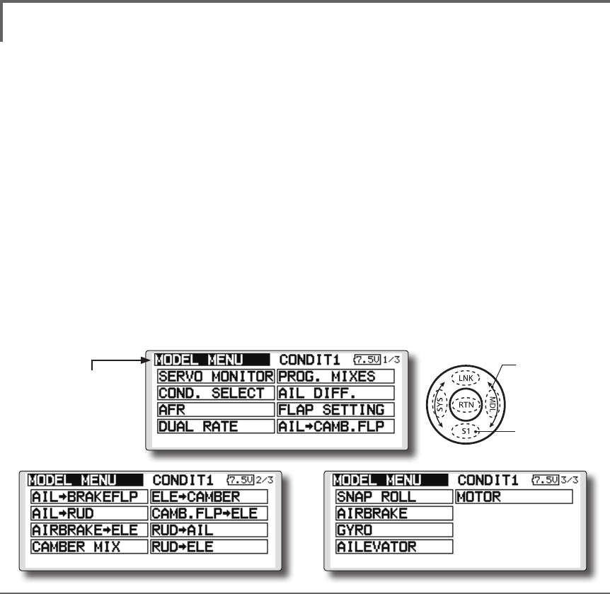
(Model Menu screen example)
*The Model Menu screen depends on the model type.
This screen is for model type 4AIL+4FLP.
Model Menu functions (Common) list
●SERVO MONITOR
Servo test and servo position display (For a
description of its functions, see the Linkage Menu
section.)
●COND.SELECT
Flight conditions addition, deletion, copy,
condition renaming, and condition delay can be set.
●AFR
Sets the angle and curve of all the operation
functions.
●DUAL RATE
A D/R curve which can be switched with a switch,
etc. can also be added.
●PROG. MIX
Program mixing which can be freely customized.
Up to 10 mixes can be used for each condition.
●Selectthe[MODEL]atthehomescreen
andcallthemodelmenushownbelowby
touchingtheRTNbutton.
●Usethetouchsensortoselectthefunction
youwanttosetandcallthesetupscreenby
touchingtheRTNbutton.
Scrolling
●Movingcursor
●Tonextpage
<SensorTouch™>
113
<Model Menu (Common Functions)>
●Selectthefunction
nameandreturntothe
precedingscreenby
touchingtheRTNbutton
orpushingtheHome/Exit
button.
<SensorTouch™>
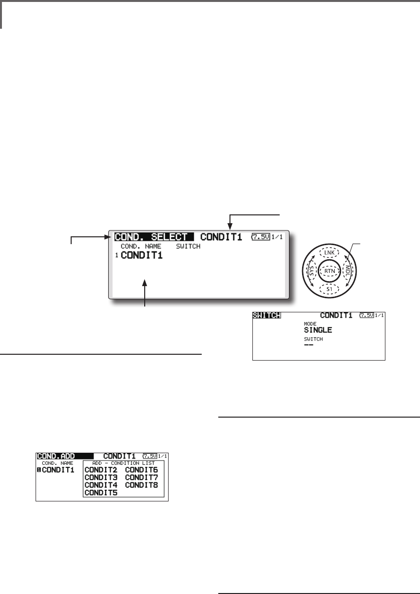
CONDIT. SELECT Flightcondition'saddition,deletion,copy,conditionrenaming,
andconditiondelaycanbeset.[Allmodeltypes]
The functions in the Model Menu can be used by
switching the settings of up to 8 flight conditions
by using the Condition Select function to add ight
conditions. Add conditions, as required.
When you do not want to use the Condition
Select function, this setting is unnecessary. In this
case, use the flight conditions assigned at initial
setting.
●Sinceswitchingbystickandleverposition,in
additiontoordinarytoggleswitch,ispossible
astheflightconditionselectorswitch,this
functioncanbelinkedwithotheroperations.
●AConditionDelayfunction canbeset.
Unnecessaryfuselagemotiongenerated
whentherearesuddenchangesintheservo
positionsandwhentherearevariationsin
theoperatingtimebetweenchannelsduring
conditionswitchingcanbesuppressed. The
delaycanbesetforeachchannel.
Whensettingthedelayfunctionatthe
switchingdestinationcondition,the
relatedfunctionchangesafteradelay
correspondingtothesetamount.
●Whenmultipleconditionswereset,their
operationprioritycanbefreelychanged.
●Theconditionnamecanbechanged.The
selectedconditionnameisdisplayedon
thescreen.Whenaconditionhasbeen
added,giveitanamewhichcanbeeasily
conrmed.
(Conditions List)
(Currently selected condition name)
●Select[CONDIT.SELECT]atthemodelmenuand
callthesetupscreenshownbelowbytouching
theRTNbutton.
(For a detailed description of the setting method, see [Switch
Setting Method] at the back of this manual.)
*The data (except the condition name) of the condition
currently being used is copied to the added condition.
Condition deletion
1.Usethetouchsensortomovethecursor
totheconditionyouwanttodeleteinthe
conditionslistandtouchtheRTNbutton.
*The number before the condition name become reverse-
video to show that it is to be deleted.
2.Movethecursorto[REMOVE]andtouchthe
RTNbutton.
*A conrmation message is displayed.
*Note that if initially operated up and down, the objective
condition changes.
3.WhentheRTNbuttonistouchedagain,the
conditionisdeleted.(Operatethetouch
sensororS1buttontostopdeletion.)
TouchtheRTNbuttontoendadjustmentand
returntothecursolmovemode.
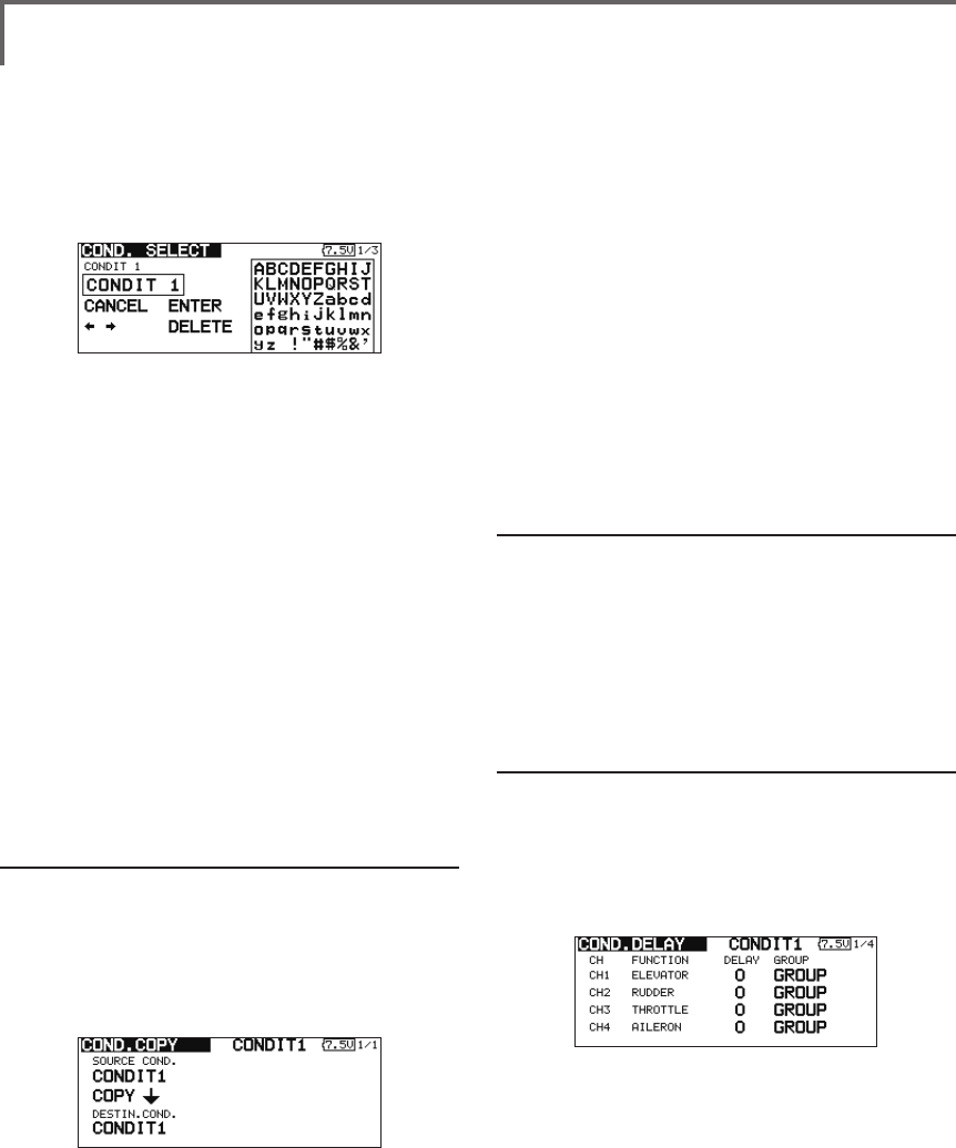
Condition name change
1.Usethetouchsensortomovethecursorto
theconditionyouwanttochangeinthe
*Perform the settings below after using the touch sensor to
move the cursor to the item you want to set.
Condition addition
1.Usethetouchsensortomovethecursorto
anyconditionintheconditionslistandtouch
theRTNbutton.
Movethecursortotheconditionyouwantto
add.
2.Movethecursorto[ADD]andtouchtheRTN
button.
*Only the No. of the conditions which can be added is
displayed.
3.AddtheconditionbytouchingtheRTN
buttonagain.TouchtheRTNbuttontoend
adjustmentandreturntothecursolmove
mode.
4.Movethecursorto[SWITCH]item,call
theswitchsetupscreenbytouchingthe
RTNbutton,andselecttheswitchandON
directiontobeusedinconditionswitching.
Scrolling
●Movingcursor
114 <Model Menu (Common Functions)>
conditionslist.
*The number before the condition name become reverse-
video to show that it is to be deleted.
2.Movethecursorto[RENAME]andtouchthe
RTNbutton.
*The condition name setup screen appears.
3.Changetheconditionnameasdescribed
below:
[Movingcursorininputbox]
Select[←]or[→],andtouchtheRTNbutton.
[Deletingacharacter]
When[DELETE]isselectedandtheRTNbutton
istouched,thecharacterimmediatelyafter
thecursorisdeleted.
[Addingacharacter]
Whenacandidatecharacterisselected
fromthecharacterlistandtheRTNbutton
istouched,thatcharacterisaddedatthe
positionimmediatelyafterthecursor.
*A name of up to 8 characters long can be entered as the
condition name. (A space is also counted as 1 character.)
5.Attheendofinput,select[ENTER]andtouch
theRTNbutton.(Toterminateinputand
returntotheoriginalstate,select[CANCEL]
andtouchtheRTNbutton.)
Condition copy
1.Usethetouchsensortomovethecursorto
anyconditionintheconditionslistandtouch
theRTNbutton.
2.Usethetouchsensortomoveto[COPY].
3.TouchtheRTNbutton.
*The copy screen appears.
4.Usethetouchsensortomovethecursorto
the"SOURCECOND."(copysource)itemand
touchtheRTNbutton.
*The models already saved are displayed at the right side of
the screen.
5.Afterusingthetouchsensortomovethe
cursortothecopysourcecondition,touch
theRTNbutton.
*The copy source condition is displayed at the "SOURCE
COND." position.
6.Usethetouchsensortomovethecursorto
"DESTIN.CND."(copydestination)andtouch
theRTNbutton.
*The models already saved are displayed at the right side of
the screen.
7.Afterusingthetouchsensortomovethe
cursortothecopydestinationcondition,
touchtheRTNbutton.
*The copy destination conditions are displayed at the
"DESTIN.COND." position.
8.Usethetouchsensortomovethecursorto
[COPY]andtouchtheRTNbutton.
9.WhentheRTNbuttonistouchedagain,copy
isexecuted.(OperatetouchsensororS1
buttontostopcopying.)
TouchtheRTNbuttontoendadjustmentand
returntothecursolmovemode.
Priority change
1.Usethetouchsensortomovethecursorto
theconditionwhosepriorityyouwantto
changeintheconditionlist.
2.Movethecursorto[UP]or[DOWN]of
[PRIORITY]andtouchtheRTNbutton.(The
lastconditionbecomesthehighestpriority.)
*The initial setting condition cannot be shifted. The priority
is the lowest.
Condition delay setting
1.Usethetouchsensortomovethecursorto
theconditionyouwanttochangeinthe
conditionlistandtouchtheRTNbutton.
2.Movethecursorto[DELAY]andtouchthe
RTNbutton.
*The condition delay setup screen appears.
3.Usethetouchsensortomovethecursorto
the"DELAY"itemofthechannelyouwantto
setandtouchtheRTNbuttontoswitchtothe
datainputmode.
Adjustthedelayamountwiththetouch
sensor.
Initialvalue:0
Adjustmentrange:0~27(maximumdelay)
TouchtheRTNbuttontoendadjustmentand
returntothecursolmovemode.
● Thesettingmode(group[GROUP]/single
[SINGLE]mode)canbeswitched.
(For more information, see the description at the back of this
manual.)
115
<Model Menu (Common Functions)>
●Selectthefunction
nameandreturntothe
precedingscreenby
touchingtheRTNbutton
orpushingtheHome/Exit
button.
<SensorTouch™>
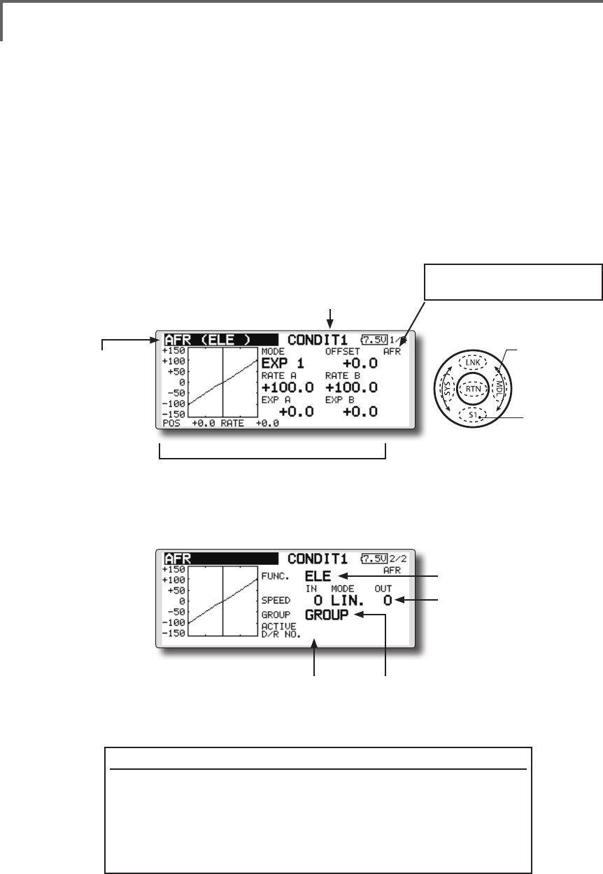
AFR Theangleandcurveofeachoperationfunctioncanbeset.[Allmodeltypes]
AFR function is used to adjust the throw and
operation curve of the stick, lever, and switch
functions for each ight condition. This is normally
used after End Point has defined the maximum
throw. When mixing is applied from one channel
to another channel, both channels can be adjusted
at the same time by adjusting the operation rate
through the AFR function.
●Operationcurveadjustment:Threetypes
ofcurves(EXP1,EXP2,andPOINT)canbe
selected.Amaximum17pointscurvecanbe
usedforthepointcurvetype.(Initialsetting:
9points)Thenumberofpointscanalsobe
increasedanddecreasedandcurvesfrom
complexcurvestosimplecurvescanbe
used.
●Operationspeedadjustment:Theoperation
speedofeachfunctionwhenthefunction
isoperated(includingatflightcondition
switching)canbeadjusted.Thefunction
operatessmoothlyataconstantspeed
correspondingtothesetspeed.
(Currently selected condition name)
(Number of D/R curves set at the currently
selected condition)
●Servospeedsetting
(For a description of the setting
method, see the description at
the back of this manual.)
●
Group/singlemodeswitch(GROUP/SINGLEl)
(For more information, see the description at the back
of this manual.)
●Operationcurvesetting
(For a description of the setting method, see the
description at the back of this manual.)
●Select[AFR]atthemodelmenuandcallthesetup
screenshownbelowbytouchingtheRTNbutton.
Function selection method
1.Usethetouchsensortomovethecursorto[FUNC.]andtouchthe
RTNbuttontoswitchtothedatainputmode.
2.Selectthedesiredfunctionbyscrollingthetouchsensortotheleft
orright,touchtheRTNbutton.
*The setting mode (group [GROUP]/single [SNGLE] mode) can be switched (For more
information, see the description at the back of this manual.)
[AFR/D/R]: Displays the currently
selected rate (AFR/D/R).
●Functionselection
Scrolling
●Movingcursor
●Selectingmode
●Adjustingvalue
●Tonextpage
116 <Model Menu (Common Functions)>
●Selectthefunction
nameandreturntothe
precedingscreenby
touchingtheRTNbutton
orpushingtheHome/Exit
button.
<SensorTouch™>
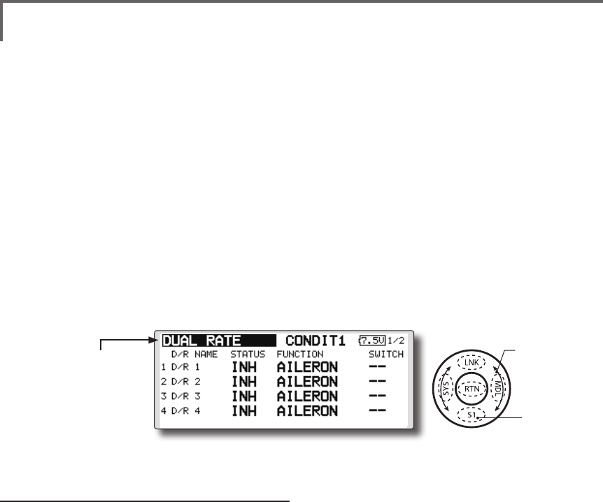
Dual rate adding
1.Movethecursortothe[INH]displayofan
unusedD/RandtouchtheRTNbuttonto
switchtothedatainputmode.
Turnitoffbyscrollingthetouchsensorto
theleftandactivatetheD/Rfunctionby
touchingtheRTNbutton.
2.Movethecursortothe"FUNCTION"itemand
touchtheRTNbuttontoswitchtothedata
inputmode.
Selectthefunctionbyscrolling thetouch
sensorandtouchtheRTNbutton.
3.Movethecursortothe[SWITCH]itemand
calltheswitchsetupscreenbytouchingthe
RTNbuttonandselecttheswitchandON
direction.Alternatemodecanbeassigned
todualrateswitch.
(For a detailed description of the setting method, see [Switch
Setting Method] at the end of this manual.)
DUAL RATE [Allmodeltypes]
D/R curves which can be switched by switch,
etc. can be added. The curve can be adjusted by the
AFR function.
● Up to6 ratescanbe addedforeach
condition.
● D/Rissetforeachconditionandisnot
reectedatotherconditions.
● D/RatthetopoftheD/Rlisthaspriority.
●Select[DUALRATE]atthemodelmenuandcall
thesetupscreenshownbelowbytouchingthe
RTNbutton.
Scrolling
●Movingcursor
●Selectingmode
●Adjustingvalue
●Tonextpage
117
<Model Menu (Common Functions)>
●Selectthefunction
nameandreturntothe
precedingscreenby
touchingtheRTNbutton
orpushingtheHome/Exit
button.
<SensorTouch™>
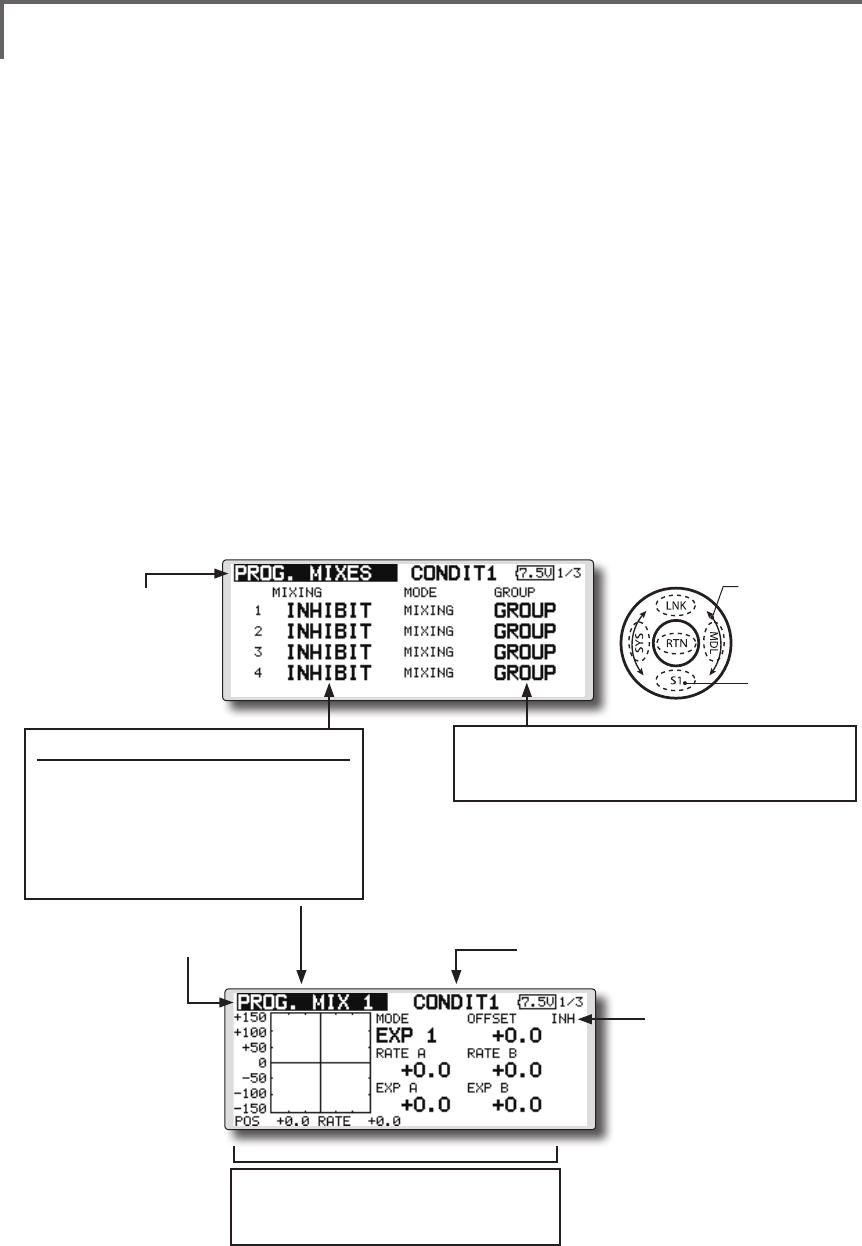
PROG. MIXES Programmixingwhichcanbefreelycustomized.Upto10
mixingscanbeusedforeachcondition.[Allmodeltypes]
Programmable mixing may be used to correct
undesired tendencies of the aircraft, and it may also
be used for unusual control congurations. Mixing
means that the motion of a command channel,
called the "master," is added to the motion of the
mixed channel, called "slave."
You may choose to have the Master's trim added
to the Slave channel response ("Trim" setting). The
mixing curve can be changed so that the undesired
tendencies can be corrected effectively by setting
the EXP1/EXP2/POINT modes. The Delay
function can be programmed for each rate. The
Delay is used to change the rate smoothly when
switching mixes. You may dene Mixing ON/OFF
switch, control or you may choose to have mixing
remaining on all the time. Mixing ON/OFF delay
time can be adjusted.
The Programmable mixing includes a powerful
link function, which allows Programmable mixing
to be linked with the special mixing functions, or
with other programmable mixing functions. The
link function can be set up for Master and Slave
channel individually.
The slave channel AFR mode (STK-STK mode)
may be selected, where the slave channel AFR and
D/R settings are observed when Link function is
set. The knob for ne tuning can be set up for every
mixing circuit. (Fine tune function)
The programmable mixing (in mixing mode)
STK to STK mixing function can be used even
when the Master is a stick or other hardware.
(Currently selected condition name)
●Select[PROG.MIXES]atthemodelmenuandcall
thesetupscreenshownbelowbytouchingthe
RTNbutton.
●Operationcurvesetting
(For a description of the setting method, see
the description at the back of this manual.)
●Mixoperatingdisplay
Mix setup screen call
● MovethecursortothemixNo.
whosefunctionyouwantto
activateandcallthesetupscreen
bytouchingtheRTNbutton.
*When the function is activated, the master and
slave channel name or is displayed.
●Group/singlemodeswitching(GROUP/SINGLE)
(For more information, see the description at the back of
this manual.)
●CurrentmixNo.
Scrolling
●Movingcursor
●Selectingmode
●Adjustingvalue
●Tonextpage
118 <Model Menu (Common Functions)>
*Perform the settings below after using the touch sensor to
move the cursor to the item you want to set.
●Group/single mode selection
1.Whenyouwanttoactivatefunctionsforonly
selectedconditions,movethecursortothe
[GROUP]itemandtouchtheRTNbuttonto
switchtothedatainputmode.
2.Turnthetouchsensortotheleftuntil[SINGLE]
startstoblinkandthentouchtheRTNbutton.
*The mode changes to the single mode [SINGLE].
*When using common settings at each conditions, remain in
the [GROUP] mode.
●Activate the function.
1.Movethecursorto[INH]andtouchtheRTN
buttontoswitchtothedatainputmode.
2.Turnthetouchsensor totheleftuntil[ACT]
startstoblinkandthentouchtheRTNbutton.
*The function is activated. (ON or OFF display)
*ON/OFF switch and mix rate are not set even through the
function is activated.
●ON/OFF switch setting
Movethecursortothe[SWITCH]item,call
theswitchsetupscreenbytouchingthe
RTNbutton,andselecttheswitchandON
direction.
(For a description of the setting method, see [Switch Setting
Method] at the back of this manual.)
*Always on when [--].
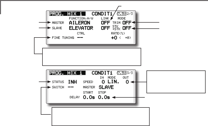
●Master channel setting
1.Movethecursortothe[FUNCTION.H/W]item
of[MASTER]andtouchtheRTNbuttonto
switchtothedatainputmode.
Selectthefunctionbyscrolling thetouch
sensorandtouchtheRTNbutton.
2.Whenyouwanttolinkthismixingwithother
mixes,movethecursortothe[LINK]itemand
touchtheRTNbuttontoswitchtothedata
inputmode.
Setthelinkmodeto[+]or[-]byscrollingthe
touchsensorandtouchtheRTNbutton.
*Check the direction by actual operation.
*Master channel control can be set to simple operating
amount of sticks and VR which do not include ATV, AFR,
D/R, and mixing setting. In this case, the switch setup
screen is displayed by touching the RTN button with "H/W"
selected by function selection. Select master channel side
control. (To terminate the "H/W" selection, select the [--]
display and touch the RTN button.
●Slave channel setting
1.Movethecursortothe[FUNCTION.H/W]
itemof[SLAVE]andtouchtheRTNbuttonto
switchtothedatainputmode.
Selectthefunctionbyscrolling thetouch
sensorandtouchtheRTNbutton.
2.Whenyouwanttolinkthismixwithother
mixes,movethecursortothe[LINK]itemand
touchtheRTNbuttontoswitchtothedata
inputmode.
Setthelinkmodeto[+]or[-]byscrollingthe
touchsensorandtouchtheRTNbutton.
*Check the direction by actual operation.
●Servospeedsetting
(For a description of the setting
method, see the description at
the back of this manual.)
●Switchselection
(For a description of the switch setting method, see the
description at the back of this manual.)
●Finetuningtrimsetting
(For a description of the setting method, see the description
at the back of this manual.)
●Linksetting
●MasterCH
●SlaveCH
●Trimmodesetting
●SlaveCHAFRmode
●ON/OFF
●MixON/OFFdelay

119
<Model Menu (Common Functions)>
TouchtheRTNbuttontoendadjustmentand
returntothecursolmovemode.
●Offset mode setting
Offset mode is function which allows
simultaneous offset control of up 4 slave functions
per circuit.
1.Use[MODE]settingtoselecttheprogram
mixingoparationmode.[MIXING]isthe
normalmixingmodeand[OFFSET]isthe
offsetmode.
2.Movethecursorto[INHIBIT]ofthemixingNo.
settotheoffsetmodeandtouchtheRTN
button.Thesetupscreenisdisplayed.
3.PresstheS1button.Page5/5isdisplayed.
4.Movethecursortothe[STATUS]itemand
switchtothedateinputmodebytouching
theRTNbutton.
5.Turnthedialtotheleftandrightuntil[ACT]
blinks,andthentouchtheRTNbutton.To
deactivatethefunction,switchto[INH].
●ON/OFF switch selection
Movethecursortothepage5/5[SWITCH]
item,calltheswitchsetupscreenby
touchingtheRTNbutton,andthenselect
theswitchandONdirection.(Foradetailed
descriptionoftheselectionmethod,see
[SwitchSelectionMethod]atthebackofthe
instructionmanual.)
●Slave No. selection
SettingoftheslaveNo.from1to4atpages
1/5~4/5isdisplayed.WhentheS1buttonis
pushed,thedisplayedslaveNo.isswitched.
●Slave function setting
Movethecursortothe[FUNCTION]itemand
switchtothedateinputmodebytouching
theRTNbutton.Selectthefunctionby
scrollingthedialandthentouchtheRTN
button.
●Offset rate setting
The function operation offset amount when
the mixing switch is ON and OFF can be set
independently.
1.Movethecursortothe[ON]or[OFF]item
andswitchtothedateinputmodeby
touchingtheRTNbutton.
2.Turnthedialtotheleftandrightandsetthe
offsetratewhentheswitchisONorOFF.
Initialsetting:0%
Settingrange:-300%~+300%
●Trim mode ON/OFF setting
1.Whenchangingthetrimmode,movethe
cursortothe[TRIM]itemandtouchtheRTN
buttontoswitchtothedatainputmode.
SelectON/OFFbyscrollingthetouchsensor
andsettheselectionbytouchingtheRTN
button.
*When mixing includes master side trim, select [ON] and
when mixing does not include master trim, select [OFF].
*Effective when a function is set at the master channel.
●Slave channel AFR mode setting (STK-STK)
1.Movethecursortothe[STK-STK]item,select
themodebyscrollingthetouchsensor,
andchangethemodebytouchingtheRTN
button.
*When link is set at the slave side, and you want to add AFR
(D/R) to the mixing rate, select [ON].
*This is effective when the linkage is the same, but the travels
are substantially different.
●Mixing curve setting
(For a description of the curve setting method, see the
description at the back of this manual.)
●Fine tuning trim setting
Operation control [CTRL], operation mode
[MODE], and rate [RATE] adjustment is possible
by [FINE TUNING] item.
(For a description of the ne tuning trim setting method, see
the description at the back of this manual.)
●Servo speed setting
Adjustment is possible with the [SPEED] item.
(For a description of the servo speed setting method, see the
description at the back of this manual).
●Mixing ON/OFF delay setting
Delay time at mix ON [START] and delay time
at mix OFF [STOP] adjustment is possible by
[DELAY] item.
*This function is inactive when a mixing switch is not set.
1.Movethe[START]or[STOP]itemandtouch
theRTNbuttontoswitchtothedatainput
mode.
2.Adjustthedelaytimebyscrollingthetouch
sensor.
Initialvalue:0.0sec
Adjustmentrange:0~4sec
(When the RTN button is touched for 1 second, the delay time
is reset to the initial value.)

120 <Model Menu (Common Functions)>
3.Afteradjustment,switchtothecursormove
modebytouchingtheRTNbutton.
*At adjustment, the delay time can be reset to the initial value
by touching the RTN button for 1 second.
3.Aftersetting,switchtothecursormovemode
bytouchingtheRTNbutton.
*At adjustment, the offset rate is reset to the initial value by
touching the RTN button for 1 second.
●Fine tuning trim setting
Operation control [CTRL], operation mode
[MODE], and rate [RATE] adjustment is possible
by [FINE TUNING] item.
(For a description of the ne tuning trim setting method, refer
to [Fine tuning trim setting] at the back of this manual.)
●Operation mode setting
The operation mode when the switch was
operated is selected. Normal mode [NORM] or
timer mode [TIME] can be selected.
[Normal mode]
After the switch is set to ON, mixing is turned
ON after the time set by start delay ([START]) has
elapsed. Similarly, after the switch was set to OFF,
mixing is turned OFF after the time set by stop
delay ([STOP]) has elapsed.
[Timer mode]
After the switch was set to ON, mixing is turned
ON after the time set by start delay ([START]) has
elapsed. Mixing is automatically turned OFF after
the time set by stop delay ([STOP]) has elapsed.
Examples of use are jet plane and scale model
retractable landing gear and cover linked mixing,
etc.
●Servo speed setting
The speed at function operation can be adjusted.
(For a description of the setting method, refer to
[Servo speed setting] at the back of the instruction
manual.)
●Delay setting
Mixing operation at mixing switch ON
([START]) and OFF ([STOP]) can be delayed by
[DELAY] item.(When switch is set.)
1.Movethecursortothe[START]or[STOP]
itemandswitchtothedateinputmodeby
touchingtheRTNbutton.
2.Turnthedialtotheleftandrightandsetthe
mixingoperationdelaytimeatswitchONor
OFF.
Initialsetting:0sec
Settingrange:0sec~35sec
121
<Model Menu (Airplane/Glider Functions) >
●Selectthe[MODELMENU]
andreturnto the home
screenbytouchingthe
RTNbuttonorpushingthe
Home/Exitbutton.
MODEL MENU (AIRPLANE/GLIDER FUNCTIONS)
The dedicated mixes, etc. usable when airplane
or glider model type is selected are displayed in
this Model Menu functions section. First use the
Model Type function of the Linkage Menu to
preset the model type, wing type, and tail type
matched to the fuselage used. Other settings reset
the data used in mixing function, etc.
These dedicated mixes can be set for each
flight condition, as required. When you want to
use the system by switching the settings for each
condition by switch or stick position, use the
Condition Select function to add ight conditions.
(Up to 8 conditions can be used)
Note:TheT18SZisdesignedsothattheairplaneand
glidermodeltypescanhandleaircraftofthesame
wingtype.
Thefunctionscommontoairplanesandgliders,
exceptsomededicatedfunctions,aresummarized
withoutregardtothemodeltype.
Thesettingitemsaredifferent,dependingonthe
numberofservos,etc.accordingtothewingtype
used.Thesetupscreensintheinstructionmanual
aretypicalexamples.
Model Menu functions list
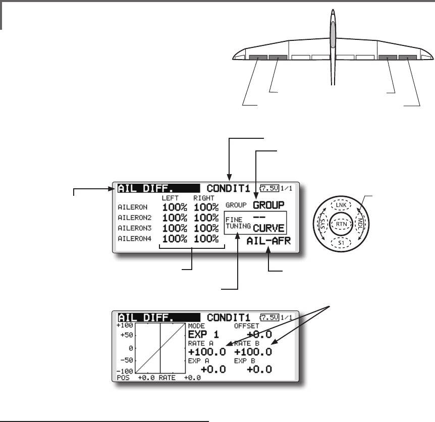
AIL DIFFERENTIAL
This function adjusts the left and right ailerons.
Roll axis correction and ne tuning with a VR are
also possible. This is convenient when making
settings during ight.
[Airplane/glider, 2 ailerons or more]
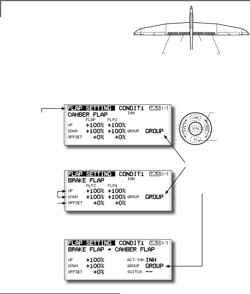
FLAP SETTING
The aps can be adjusted independently. For a
4 aps model, the camber aps can be mixed with
the brake aps. [Airplane/glider, 2 aps or more]
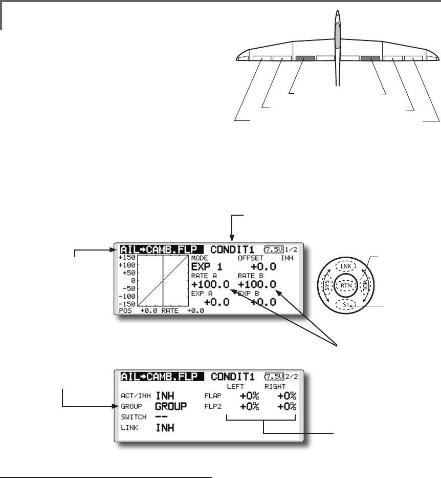
AIL to CAMBERFLP
This mix operates the camber flaps in
the aileron mode. It improves the operation
characteristic of the roll axis. [Airplane/glider, 2
ailerons + 2 aps or more]
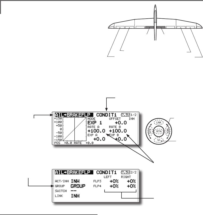
AIL to BRAKEFLP
This mix operates the brake aps in the aileron
mode. It improves the operation characteristic of
the roll axis. [Airplane/glider, 4 aps or more]
AIL to RUD
This mix is used when you want to operate the
rudder at aileron operation. Banking at a shallow
bank angle is possible. [Airplane/glider, general]
AIRBRAKE to ELE
This mix is used to correct operation of the
airbrakes (spoilers) when landing. [Airplane/
glider, general]
(Model Menu screen example)
*The Model Menu screen depends on the model type.
This screen is for model type 4AIL+4FLP.
●Selectthe[MODEL]atthehomescreen
andcallthemodelmenushownbelowby
touchingtheRTNbutton.
●Usethetouchsensortoselectthefunction
youwanttosetandcallthesetupscreenby
touchingtheRTNbutton.
Scrolling
●Movingcursor
●Tonextpage
<SensorTouch™>
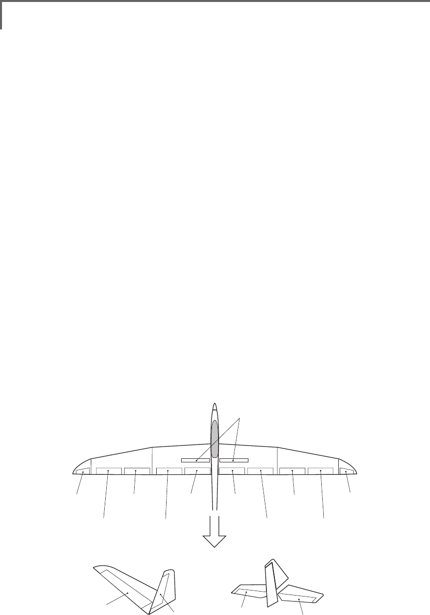
122 <Model Menu (Airplane/Glider Functions) >
AIL 3
(Chip Aileron) AIL 4
(Chip Aileron)
AIL1
(Main Aileron) AIL 2
(Main Aileron)
FLP 2
(Camber Flap)
FLP 1
(Camber Flap)
ELEVATOR
(ELEVATOR 2)
V-TAIL AILVATOR
FLP 3
AIR BRAKE
(Brake Flap)
FLP 4
(Brake Flap) RUDDER 2
Winglet
RUDDER 1
RUDDER
(RUDDER 2)
Winglet
at Flying wing at Flying wing
( ) ( )
ELEVATOR ELEVATOR 2
(AILERON 5)
(AILERON 6)
RUD to AIL
This mix is used to correct roll maneuvers,
knife edge, etc. of stunt planes. [Airplane/glider,
general]
CAMBER Mix
This mix adjusts the camber and corrects the
elevators. [Airplane/glider, 2 ailerons or more]
ELE to CAMBER
This mix is used when you want to the mix
camber aps with elevator operation. Lifting force
can be increased at elevators up. [Airplane/glider,
2 ailerons or more]
CAMBERFLP to ELE
This mix is used to correct for attitude changes
when the camber aps are being used. [Airplane/
glider, 2 ailerons + 1 ap or more]
BUTTERFLY (Crow)
This function is used when powerful brake
operation is necessary. [Glider, 2 ailerons or
more]
TRIM MIX 1/2
The ailerons, elevators, and flaps trim offset
rate can be called by switch or condition selection.
[Glider, 2 ailerons or more]
AIRBRAKE
This function is used when airbrakes are
necessary when landing or when diving, etc.
during ight. (Airplane, general)
GYRO
This is a dedicated mix when a GYA Series
gyro is used. [Airplane/glider, general]
V-TAIL
This function adjusts the elevators and
rudder of V-tail models. [Airplane/glider, V-tail
specications]
AILEVATOR
This function adjusts the elevators and ailerons
of models with elevator specications. [Airplane/
glider, elevator specications]
WINGLET
This function adjusts the left and right rudders
of winglet models. [Airplane/glider, winglet
specications]
MOTOR
The operation speed when the motor of F5B
and other EP gliders is started by switch can be
set. [EP glider, general]
RUD to ELE
This function is used to correct roll maneuvers,
knife edge, etc. of stunt planes. [Airplane,
general]
SNAP ROLL
This function selects the snap roll switch and
adjusts the steering angle of each rudder. Servo
speed can also be adjusted. [Airplane general]
123
<Model Menu (Airplane/Glider Functions) >
●Selectthefunction
nameandreturntothe
precedingscreenby
touchingtheRTNbutton
orpushingtheHome/Exit
button.
<SensorTouch™>
AIL 3
(Chip Aileron) AIL 4
(Chip Aileron)
AIL1
(Main Aileron) AIL 2
(Main Aileron)
AIL DIFF. [Airplane/glider,2aileronsormore]
The left and right aileron differential can be
adjusted independently. The differential rate can
also be adjusted according to the flying state by
setting a ne tuning VR.
●CallstheAFRscreendirectly
whenadjustingaileron
operationAFR.
●FinetuningVRsetting
*The graph is operated by setting a VR, etc.
●Group/singlemodeswitching
(For more information, refer to the
description at the back of this manual.)
●Aileronleft/rightadjustment
<Wing type: 4 ailerons screen>
*The display screen is an example. The actual screen
depends on the Model Type.
●Overalladjustmentby
RateAandRateB.
Setting method
●Movethecursortotheaileron(AIL)1~4left(or
right)settingitemandtouchtheRTNbutton
toswitchtothedatainputmode.
Adjusttheaileronangleswhenthestickis
movedtotheleft(orright)end.
TouchtheRTNbuttontoendadjustmentand
returntothecursolmovemode.
*The aileron AFR screen can be directly called from the AIL
differential setup screen. ([AIL-AFR] )
●Whensettingthefine tuningVR,movethe
cursortothe"--"itemandtouchtheRTN
buttontocalltheselectionscreen,andthen
selectthenetuningVR.
TouchtheRTNbuttontoendadjustmentand
returntothecursolmovemode.
●Thenetuningratecanbesetbycurve.
(Currently selected condition name)
●Select[AILDIFF.]atthemodelmenu
andcallthesetupscreenshown
belowbytouchingtheRTNbutton.
Scrolling
●Movingcursor
●Selectingmode
●Adjustingvalue
124 <Model Menu (Airplane/Glider Functions) >
●Selectthefunction
nameandreturntothe
precedingscreenby
touchingtheRTNbutton
orpushingtheHome/Exit
button.
<SensorTouch™>
FLP 2
(Camber Flap)
FLP 1
(Camber Flap)
FLP 3
(Brake Flap) FLP 4
(Brake Flap)
FLAP SETTING [Correspondingmodeltype]:Airplane/
glider,2apsormore]
The up/down travel of each flap (camber flaps:
FLP1/2, brake flaps: FLP3/4) can be adjusted
independently at each servo according to the wing type.
●Theoperationreferencepointofeachapcanbe
offset
The camber aps of a 4-ap model can be mixed
with the brake aps. (Brake FLP to camber FLP)
●AnON/OFFswitchcanbeset. <Wing type: 4 aps screen>
*The display screen is an example. The actual
screen depends on the model type.
Setting method
●Movethecursortotheflap(FLP)1~4upor
downitemaccordingtothewingtypeand
touchtheRTNbuttontoswitchtothedata
inputmode.
Adjustthetravelindependently.
●Tooffsettheoperationreferencepoint
ofeachflap,movethecursortothe
correspondingoffsetitem.Usethetouch
sensortooffsetthereferencepoint.
TouchtheRTNbuttontoendadjustmentand
returntothecursolmovemode.
●Operation
referencepoint
offset
●Upside/Down
sideadjustment
●Group/singlemode
switching
(For more information, refer to
the description at the back of
this manual.)
●WhenusingbrakeFLPtocamberFLPmixing,
movethecursortothe[ACT/INH]itemand
turnthetouchsensortotheleftandtouch
theRTNbutton.(ONisdisplayed.)
Whensettingaswitch,movethecursorto
the[--]itemoftheswitchandtouchtheRTN
buttontocalltheselectionscreen,andthen
selecttheswitchandsetitsONdirection.
(AlwaysONat"--"setting)
(Foradescriptionoftheswitchselection
method,seethedescriptionatthebackof
thismanual.)
(CAMBERFLPsettingscreen)
(BRAKEFLPsettingscreen)
(B.FLPtoC.FLPsettingscreen)
●Select[FLAPSETTING]atthemodelmenu
andcallthesetupscreenshownbelowby
touchingtheRTNbutton.
Scrolling
●Movingcursor
●Selectingmode
●Adjustingvalue
●Tonextpage
125
<Model Menu (Airplane/Glider Functions) >
●Selectthefunction
nameandreturntothe
precedingscreenby
touchingtheRTNbutton
orpushingtheHome/Exit
button.
<SensorTouch™>
AIL 3
(Chip Aileron) AIL 4
(Chip Aileron)
AIL1
(Main Aileron) AIL 2
(Main Aileron)
FLP 2
(Camber Flap)
FLP 1
(Camber Flap)
AIL to CAMB.FLP [Correspondingmodeltype]: Airplane/
glider,2ailerons+2apsormore
This mix operates the camber flaps (FLP1/2)
in the aileron mode. When the aileron stick
is manipulated, the ailerons and camber flaps
perform aileron operation simultaneously and
the operation characteristic of the roll axis is
improved.
●Theaileronleft/rightmixingrateofeachapservo
canbene-tuned.
●Amixingcurvecanbeset.
●AnON/OFFswitchcanbeset.
●Linkingispossible:Linkthismixtoothermixes.
●Mixingcurvesetting
*For a description of the curve setting method, see the
description at the back of this manual.
●Adjustmentofeach
apservo
●Left/rightoverall
adjustmentat
RateAandRateB
Setting method
●MovethecursortotheACT/INHitemand
touchtheRTNbuttontoswitchtothedata
inputmode.
Turnthetouchsensortotheleftandtouch
theRTNbutton.(ONisdisplayed.)
●Whensettingaswitch,movethecursorto
the[--]itemoftheswitchandtouchtheRTN
buttontocalltheselectionscreen,andthen
selecttheswitchandsetitsONdirection.
(AlwaysONat"--"setting)
(Foradescriptionoftheswitchselection
method,seethedescriptionatthebackof
thismanual.)
●Movethecursortotheleftorrightitemof
eachapservoandtouchtheRTNbuttonto
switchtothedatainputmode.
Adjustthemixingratewiththetouchsensor.
TouchtheRTNbuttontoendadjustmentand
returntothecursolmovemode.
*When the mixing direction is reversed by the linkage,
adjustments can be made by changing the mixing rate
polarity (+ or -).
●Amixingcurvecanbeset.
(Foradescriptionofthemixingcurvesetting
method,seethedescriptionatthebackof
thismanual.)
●Tosetlinking,movethecursortothe[LINK]
itemandtouchtheRTNbuttontoswitchto
thedatainputmode.
SetittoONandtouchtheRTNbutton.
(Currently selected condition name)
●Select[AILtoCAMB.FLP]atthemodel
menuandcallthesetupscreenshown
belowbytouchingtheRTNbutton.
●Group/singlemode
switching
(For more information, refer
to the description at the back
of this manual.)
*The display screen is an example. The actual
screen depends on the model type.
Scrolling
●Movingcursor
●Selectingmode
●Adjustingvalue
●Tonextpage
126 <Model Menu (Airplane/Glider Functions) >
●Selectthefunction
nameandreturntothe
precedingscreenby
touchingtheRTNbutton
orpushingtheHome/Exit
button.
<SensorTouch™>
AIL 3
(Chip Aileron) AIL 4
(Chip Aileron)
AIL1
(Main Aileron) AIL 2
(Main Aileron)
FLP 3
(Brake Flap) FLP 4
(Brake Flap)
AIL to BRAKEFLP [Correspondingmodeltype]:Airplane/
glider,4apsormore
This mix operates the brake flaps (FLP3/4)
in the aileron mode. When the aileron stick
is manipulated, the aileron and brake flaps
perform the aileron operation simultaneously
and the operation characteristic of the roll axis is
improved.
●Theaileronleftandrightmixingratescanbe
adjustedforeachapservo.
●Amixingcurvecanbeset.
●MixingduringightcanbeturnedON/OFFby
settingaswitch.(AlwaysONat[--]setting)
●Linkingcanbeset:Linkthismixtoothermixes.
●Setting method
●MovethecursortotheACT/INHitemand
touchtheRTNbuttontoswitchtothedata
inputmode.
Turnthetouchsensortotheleftandtouch
theRTNbutton.(ONisdisplayed.)
●Whensettingaswitch,movethecursorto
the[--]itemoftheswitchandtouchtheRTN
buttontocalltheselectionscreen,andthen
selecttheswitchandsetitsONdirection.
(AlwaysONat"--"setting)
(Foradescriptionoftheswitchselection
method,seethedescriptionatthebackof
thismanual.)
●Movethecursortotheleftorrightbuttonof
eachapservoandtouchtheRTNbuttonto
switchtothedatainputmode.
Adjustthemixingratewiththetouchsensor.
TouchtheRTNbuttontoendadjustmentand
returntothecursolmovemode.
*When the mixing direction is reversed by the linkage,
adjustments can be made by reversing the mixing rate
polarity (+ or -).
●Amixingcurvecanbeset.
(Foradescriptionofthecurvesetting
method,seethedescriptionatthebackof
thismanual.)
●Tosetlinking,movethecursortotheLinkitem
andtouchtheRTNbuttontoswitchtothe
datainputmode.
SetittoONandtouchtheRTNbutton.
●Mixingcurvesetting
*For a description of the curve setting method, see the
description at the back of this manual.
●Adjustmentof
eachapservo
●Left/rightoverall
adjustmentatRate
AandRateB
(Currently selected condition name)
●Select[AILtoBRAKEFLP]atthemodel
menuandcallthesetupscreenshown
belowbytouchingtheRTNbutton.
●Group/singlemode
switching
(For more information, refer
to the description at the
back of this manual.)
*The display screen is an example. The actual
screen depends on the model type.
Scrolling
●Movingcursor
●Selectingmode
●Adjustingvalue
●Tonextpage
127
<Model Menu (Airplane/Glider Functions) >
●Selectthefunction
nameandreturntothe
precedingscreenby
touchingtheRTNbutton
orpushingtheHome/Exit
button.
<SensorTouch™>
RUDDER 2
RUDDER RUDDER
V-TAIL
RUDDER 2
Winglet
RUDDER 1
Winglet
at Flying wing at Flying wing
( ) ( )
AIL 3 AIL 3
(Chip Aileron) (Chip Aileron)
AIL1
(Main Aileron) AIL 2
(Main Aileron)
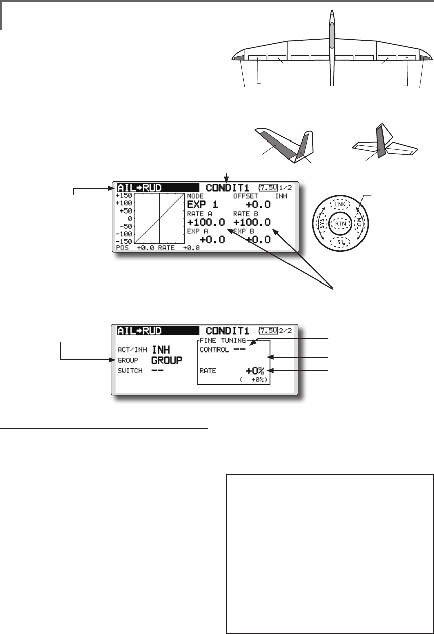
AIL to RUD [Correspondingmodeltype]:
Airplane/glider,general
Use this mix when you want to mix the rudders
with aileron operation.
●Amixingcurvecanbeset.
●MixingduringightcanbeturnedON/OFFby
settingaswitch.(AlwaysONat[--]setting)
●Themixingratecanbene-tunedbysettingaVR.
Setting method
●MovethecursortotheACT/INHitemand
touchtheRTNbuttontoswitchtothedata
inputmode.
Turnthetouchsensortotheleftandtouch
theRTNbutton.(ONisdisplayed.)
●Whensettingaswitch,movethecursorto
the[--]itemoftheswitchandtouchtheRTN
buttontocalltheselectionscreen,andthen
selecttheswitchandsetitsONdirection.
(AlwaysONat"--"setting)
(Foradescriptionoftheswitchselection
method,seethedescriptionatthebackof
thismanual.
●WhensettingaVR,movethecursortothe
FineTuning"--"itemandtouchtheRTN
buttontocalltheselectionscreen,andthen
selecttheVR.Theadjustmentratecanbe
set.TheVRoperationmodecanalsobe
selected.
[FinetuningVRoperationmode]
[LIN.] Mixingrate0%atcenterofVR.
WhentheVRisturnedclockwiseand
counterclockwise,themixingrate
increasesanddecreases,respectively.
[ATL+]Mixingrate0%atleftendofVR.
WhentheVRisturned,themixingrate
increases.
[ATL-] Mixingrate0%atrightend ofVR.
WhentheVRisturned,themixingrate
increases.
[SYM.]WhentheVRisturnedtotheleftor
rightoftheneutralposition,themixing
rateincreases.
●Mixingcurvesetting
*For a description of the curve setting method, see the
description at the back of this manual. ●Left/rightoverall
adjustmentatRate
AandRateB
(Currently selected condition name)
●Select[AILtoRUD]atthemodel
menuandcallthesetupscreen
shownbelowbytouchingtheRTN
button.
●Group/singlemode
switching
(For more information, refer
to the description at the
back of this manual.)
*The display screen is
an example. The actual
screen depends on the
model type.
●FinetuningVRsetting
●Adjustmentrate
●Operationmode
●Amixingcurvecanbeset.
(Foradescriptionofthecurvesetting
method,seethedescriptionatthebackof
thismanual.)
Scrolling
●Movingcursor
●Selectingmode
●Adjustingvalue
●Tonextpage
128 <Model Menu (Airplane/Glider Functions) >
●Selectthefunction
nameandreturntothe
precedingscreenby
touchingtheRTNbutton
orpushingtheHome/Exit
button.
<SensorTouch™>
ELEVATOR ELEVATOR 2
AILVATOR
AIR BRAKE
V-TAIL
ELEVATOR ELEVATOR 2
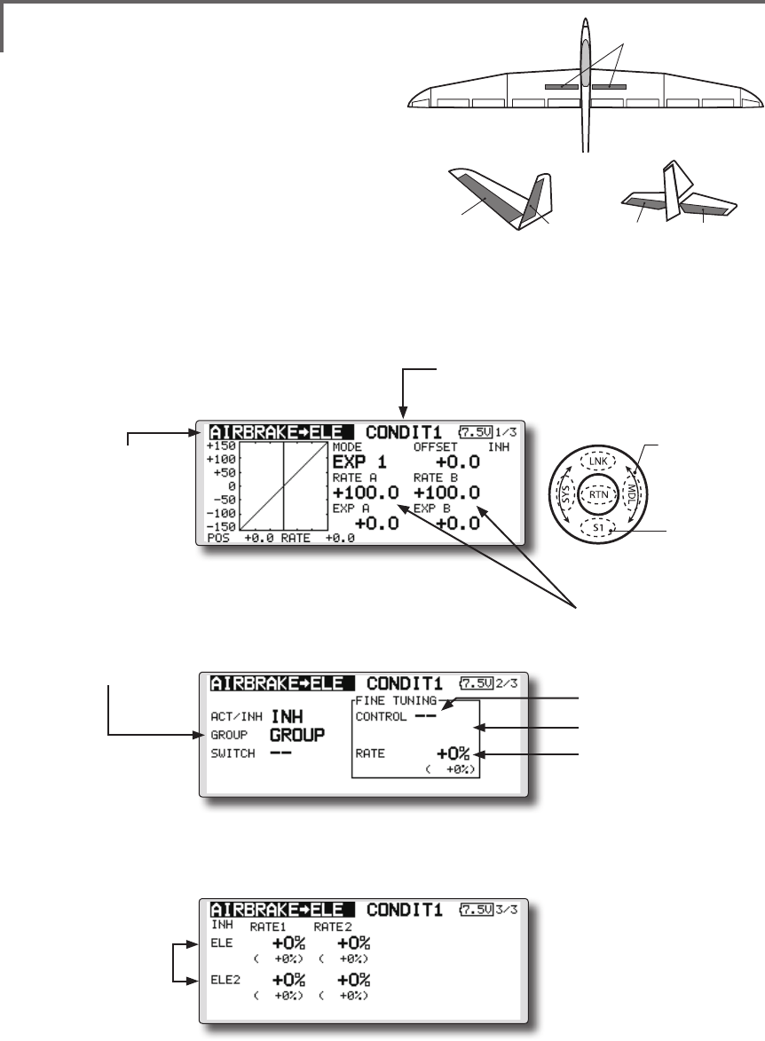
AIRBRAKE to ELE [Correspondingmodeltype]:
Airplane/glider,general
This mix is used when you want to mix the
elevators with airbrake (spoiler) operation. It
raises the elevators to correct for dropping of the
nose during airbrake operation.
*This function does not operate when airbrake is not assigned
at the Function menu in the Linkage Menu.
●TheRate1side/Rate2sidemixingratewiththe
elevatorservoscanbeadjusted.
●Amixingcurvecanbeset.
●MixingduringightcanbeturnedON/OFFby
settingaswitch.(AlwaysONat[--]setting)
●Themixingratecanbene-tunedbysettingaVR.
●FinetuningVRsetting
●Group/singlemode
switching
(For more information,
refer to the description at
the back of this manual.)
●Overalladjustmentby
RateAandRateB.
(Currently selected condition name)
●Select[AIRBRAKEtoELE]atthemodel
menuandcallthesetupscreenshown
belowbytouchingtheRTNbutton.
●Mixingcurvesetting
*For a description of the curve setting method, see the
description at the back of this manual.
●Adjustmentrate
●Operationmode
●Adjustmentof
eachelevator
servo
*The display screen is an example. The actual
screen depends on the model type.
Scrolling
●Movingcursor
●Selectingmode
●Adjustingvalue
●Tonextpage

129
<Model Menu (Airplane/Glider Functions) >
Setting method
●MovethecursortotheACT/INHitemand
touchtheRTNbuttontoswitchtothedata
inputmode.
Turnthetouchsensortotheleftandtouch
theRTNbutton.(ONisdisplayed.)
●Whensettingaswitch,movethecursorto
the[--]itemoftheswitchandtouchtheRTN
buttontocalltheselectionscreen,andthen
selecttheswitchandsetitsONdirection.
(AlwaysONat"--"setting)
(Foradescriptionoftheswitchselection
method,seethedescriptionatthebackof
thismanual.
●WhensettingaVR,movethecursortothe
Finetuning"--"itemandtouchtheRTNbutton
tocalltheselectionscreen,andthenselect
theVR.Theadjustmentratecanbeset.The
VRoperationmodecanalsobeset.
(ForadescriptionofthenetuningVRsetting
method,seethedescriptionatthebackof
thismanual.)
●Amixingcurvecanbeset.
(Foradescriptionofthecurvesetting
method,seethedescriptionatthebackof
thismanual.)
[FinetuningVRoperationmode]
[LIN.] Mixingrate0%atcenterofVR.
WhentheVRisturnedclockwiseand
counterclockwise,themixingrate
increasesanddecreases,respectively.
[ATL+]Mixingrate0%atleftendofVR.
WhentheVRisturned,themixingrate
increases.
[ATL-] Mixingrate0%atrightend ofVR.
WhentheVRisturned,themixingrate
increases.
[SYM.]WhentheVRisturnedtotheleftor
rightoftheneutralposition,themixing
rateincreases.
130 <Model Menu (Airplane/Glider Functions) >
●Selectthefunction
nameandreturntothe
precedingscreenby
touchingtheRTNbutton
orpushingtheHome/Exit
button.
<SensorTouch™>
RUDDER 2
RUDDER RUDDER
V-TAIL
RUDDER 2
Winglet
RUDDER 1
Winglet
at Flying wing at Flying wing
( ) ( )
AIL 3 AIL 3
(Chip Aileron) (Chip Aileron)
AIL1
(Main Aileron) AIL 2
(Main Aileron)
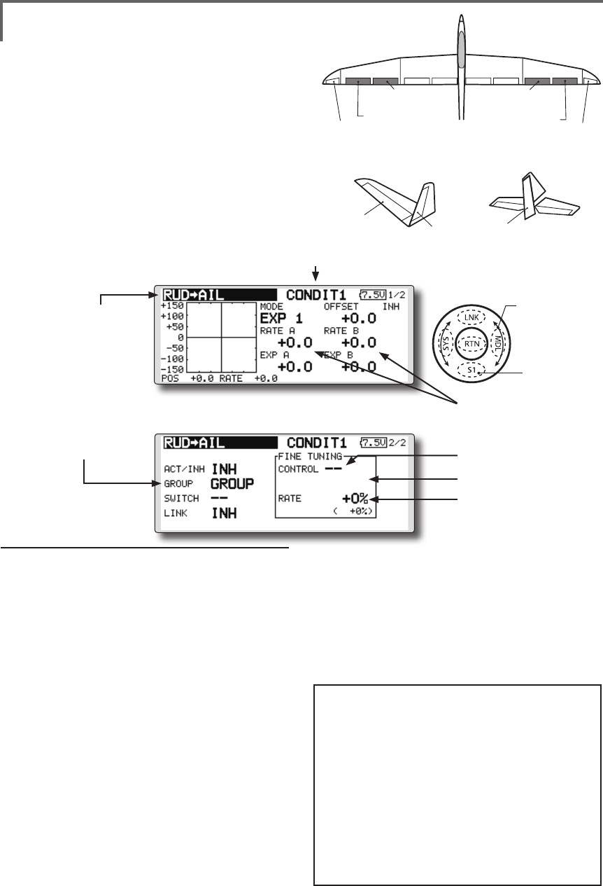
RUD to AIL [Correspondingmodeltype]:
Airplane/glider,general
This function is used when you want to mix
the ailerons with rudder operation. It is used
when rudder is applied during roll maneuvers,
knife edge, etc. of stunt planes. It can be used to
bank scale models, large models, etc. like a full
size plane.
●Amixingcurvecanbeset.
●MixingduringightcanbeturnedON/OFFby
settingaswitch.(AlwaysONat[--]setting)
●Linkingcanbeset:Linkthismixtoothermixes.
●Themixingratecanbene-tunebysettingaVR.
Setting method
●MovethecursortotheACT/INHitemand
touchtheRTNbuttontoswitchtothedata
inputmode.
Turnthetouchsensortotheleftandtouch
theRTNbutton.(ONisdisplayed.)
●Whensettingaswitch,movethecursorto
the[--]itemoftheswitchandtouchtheRTN
buttontocalltheselectionscreen,andthen
selecttheswitchandsetitsONdirection.
(AlwaysONat"--"setting)
(Foradescriptionoftheswitchselection
method,seethedescriptionatthebackof
thismanual.
●WhensettingaVR,movethecursortothe
Finetuning"--"itemandtouchtheRTN
buttontocalltheselectionscreenandthen
selecttheVR.Theadjustmentratecanbe
set,.
TheVRoperationmodecanalsobeset.
(ForadescriptionofthenetuningVRsetting
method,seethedescriptionatthebackof
thismanual.)
●Amixingcurvecanbeset.
(Foradescriptionofthecurvesetting
method,seethedescriptionatthebackof
thismanual.)
●Whenlinking:movethecursortothe[LINK]
itemandtouchtheRTNbuttontoswitchto
thedatainputmode.Turnthetouchsensor
totheleftandtouchtheRTNbutton.(ONis
displayed.)
●Mixingcurvesetting
*For a description of the curve setting method, see the
description at the back of this manual.
●Left/rightoverall
adjustmentatRateA
andRateB
(Currently selected condition name)
●Select[RUDtoAIL]atthemodel
menuandcallthesetupscreen
shownbelowbytouchingthe
RTNbutton.
●Group/singlemode
switching
(For more information,
refer to the description at
the back of this manual.)
*The display screen is an example.
The actual screen depends on the
model type.
●FinetuningVRsetting
●Adjustmentrate
●Operationmode
[FinetuningVRoperationmode]
[LIN.] Mixingrate0%atcenterofVR.
WhentheVRisturnedclockwiseand
counterclockwise,themixingrate
increasesanddecreases,respectively.
[ATL+]Mixingrate0%atleftendofVR.
WhentheVRisturned,themixingrate
increases.
[ATL-] Mixingrate0%atrightend ofVR.
WhentheVRisturned,themixingrate
increases.
[SYM.]WhentheVRisturnedtotheleftor
rightoftheneutralposition,themixing
rateincreases.
Scrolling
●Movingcursor
●Selectingmode
●Adjustingvalue
●Tonextpage
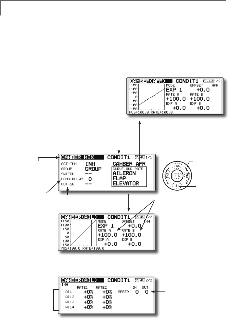
131
<Model Menu (Airplane/Glider Functions) >
●Selectthefunction
nameandreturntothe
precedingscreenby
touchingtheRTNbutton
orpushingtheHome/Exit
button.
<SensorTouch™>
CAMBER MIX [Correspondingmodeltype]:Airplane/glider,2aileronsormore
This function adjusts the AFR (D/R) rate
of camber operation which operates the wing
camber (ailerons, camber flaps, brake flaps) in
the negative and positive directions. The aileron,
flap, and elevator rates can also be adjusted
independently by curve, and attitude changes
caused by camber operation can be corrected.
*Initial setting assigns camber operation to side lever LS.
●Theup/downsideratesoftheaileron,ap,and
elevatorservoscanbeadjustedbycurve.When
themixingdirectionisreversedbythelinkage,
adjustmentscanbemadebychangingthe
mixingratepolarity(+or-).
●MixingduringightcanbeturnedON/OFFby
settingaswitch.(AlwaysONat[--]setting)
●Adelaycanbesetforeachcondition.Acut
switchwhichcanturnOFFthedelayfunctioncan
beset.
●Thespeedoftheaileron,ap,andelevatorservos
canbeset.(INside/OUTside)
●Conditiondelay
cutswitch
●Conditiondelay
setting
●CamberAFR(D/R)setupscreen
call
(For a description of the setting method, refer
to the AFR function.)
●Servospeedsetting
(For a description of the setting
method, see the description at
the back of this manual.)
●Overalladjustmentby
RateAandRateB
●Aileronrate
adjustment
(Currently selected condition name)
●Select[CAMBERMIX]atthemodel
menuandcallthesetupscreen
shownbelowbytouchingtheRTN
button.
●Mixingcurvesetting
*For a description of the curve setting method, see the
description at the back of this manual.
*The display screen is an example. The actual
screen depends on the model type.
(Curve/ratesettingscreen)
Scrolling
●Movingcursor
●Selectingmode
●Adjustingvalue
●Tonextpage
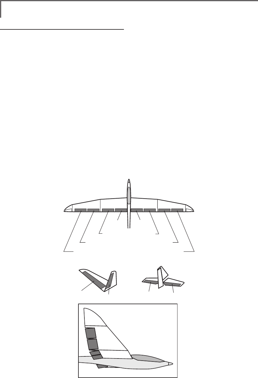
132 <Model Menu (Airplane/Glider Functions) >
AIL 3
(Chip Aileron) AIL 4
(Chip Aileron)
AIL1
(Main Aileron) AIL 2
(Main Aileron)
FLP 2
(Camber Flap)
FLP 1
(Camber Flap)
ELEVATOR ELEVATOR 2
V-TAIL
ELEVATOR ELEVATOR 2
AILVATOR
FLP 3
(Brake Flap) FLP 4
(Brake Flap)
Setting method
●MovethecursortotheACT/INHitemand
touchtheRTNbuttontoswitchtothedata
inputmode.
Turnthetouchsensortotheleftandtouch
theRTNbutton.(ONisdisplayed.)
●Whensettingaswitch,movethecursorto
the[--]itemoftheswitchandtouchtheRTN
buttontocalltheselectionscreen,andthen
selecttheswitchandsetitsONdirection.
(AlwaysONat"--"setting)
(Foradescriptionoftheswitchselection
method,seethedescriptionatthebackof
thismanual.)
●Whensettingaconditiondelay,movethe
cursortothe[COND.DELAY]itemandtouch
theRTNbuttontoswitchtothedatainput
mode.
Setthedelaywiththetouchsensor.
TouchtheRTNbuttontoendadjustmentand
returntothecursolmovemode.
Whensettingacutswitch, movethecursor
to[CUT-SW]itemandtouchtheRTNbutton
tocalltheselectionscreen,andthenselect
theswitchandsetitsONdirection.(Always
ONat[--]setting)
(Foradescriptionoftheconditiondelay
function,seethedescriptionatthebackof
thismanual.)
●CamberAFR(D/R)screencall
MovethecursortotheCamberAFRitem
andtouchtheRTNbuttontocallthesetup
screen.(Foradescriptionofthesetup
method,seethedescriptionatthebackof
thismanual.)
(Curve/ratesetupscreen)
●Thecurveandrateareadjustedbycalling
theaileron,flap,andelevatorcurve/rate
screens.
Therateandcurveofeachservocanbeset
bycallingeachscreen.(Foradescriptionof
thecurvesettingmethod,seethedescription
atthebackofthismanual.)
Theservospeedcanalsobeadjusted.
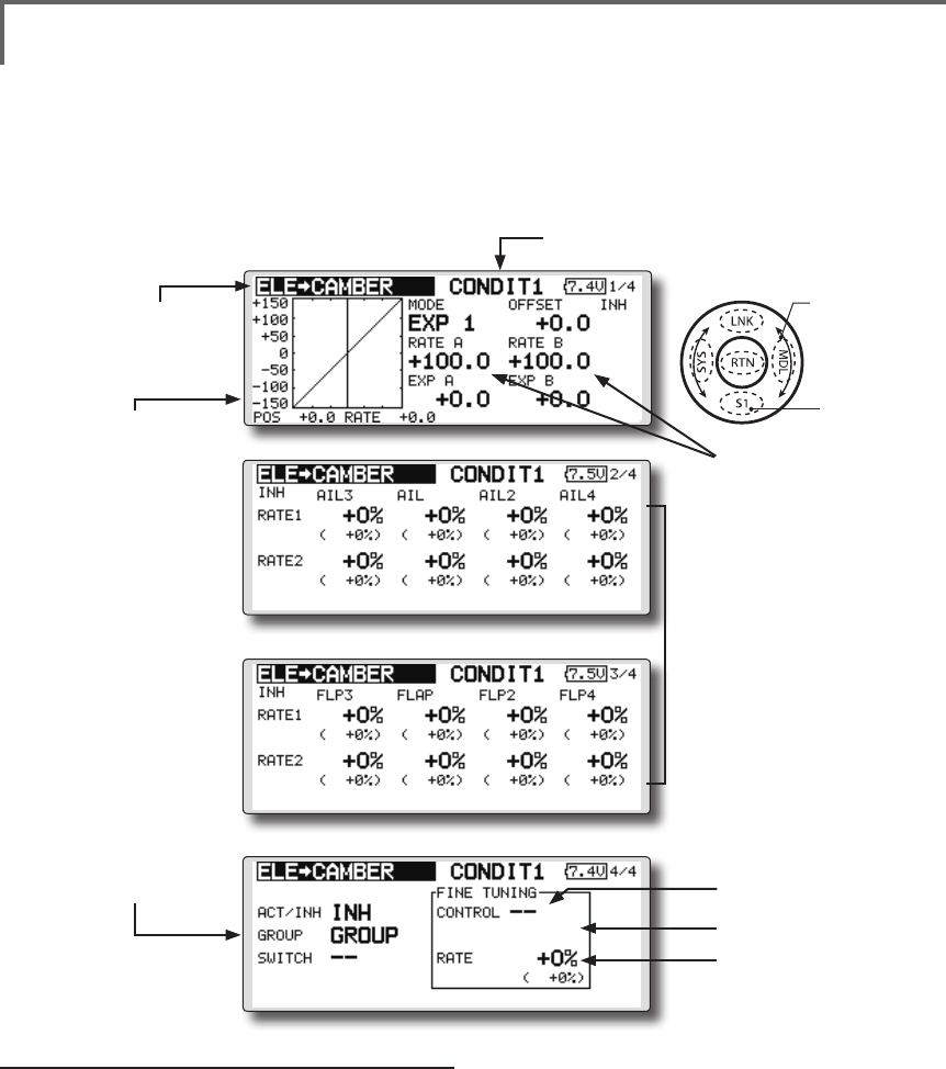
133
<Model Menu (Airplane/Glider Functions) >
●Selectthefunction
nameandreturntothe
precedingscreenby
touchingtheRTNbutton
orpushingtheHome/Exit
button.
<SensorTouch™>
ELE to CAMBER [Correspondingmodeltype]:Airplane/glider,2aileronsormore
This function is used when you want to mix the
camber aps with elevator operation. When used,
the aps are lowered by up elevator, and lift can
be increased.
Note: Tailless wing elevator can be operated
when this mix is activated.
●Amixingcurvecanbeset.
●MixingduringightcanbeturnedON/OFFby
settingaswitch.(AlwaysONat[--]setting)
●Themixingratecanbene-tunedbysettingaVR.
●Aileronsandflapsrate
adjustment
1.Selecttherateboxand
touchtheRTNbuttonto
switchtothedatainput
mode.
2.Adjusttheratesby
scrollingthetouchsensor.
3.TouchtheRTNbutton
toendadjustmentand
returntothecursolmove
mode.
Setting method
●MovethecursortotheACT/INHitemand
touchtheRTNbuttontoswitchtothedata
inputmode.
Turnthetouchsensortotheleftandtouch
theRTNbutton.(ONisdisplayed.)
●Whensettingaswitch,movethecursorto
the[--]itemoftheswitchandtouchtheRTN
buttontocalltheselectionscreen,andthen
selecttheswitchandsetitsONdirection.
(AlwaysONat"--"setting)
(Foradescriptionoftheswitchselection
method,seethedescriptionatthebackof
thismanual.)
●WhensettingaVR,movethecursortothe
Finetuning"--"itemandtouchtheRTNbutton
tocalltheselectionscreen,andthenselect
theVR.Theadjustmentratecanbeset.
TheVRoperationmodecanalsobe
selected.
●Amixingcurvecanalsobeset.
(Foradescriptionofthecurvesetting
method,seethedescriptionatthebackof
thismanual.)
●Group/singlemode
switching
(For more information,
refer to the description at
the back of this manual.)
●Overalladjustmentby
RateAandRateB.
(Currently selected condition name)
●Select[ELEtoCAMBER]atthemodel
menuandcallthesetupscreenshown
belowbytouchingtheRTNbutton.
●Mixingcurvesetting
*For a description of the
curve setting method,
see the description at the
back of this manual.
*The display screen is an
example. The actual screen
depends on the model type.
●FinetuningVRsetting
●Adjustmentrate
●Operationmode
Scrolling
●Movingcursor
●Selectingmode
●Adjustingvalue
●Tonextpage
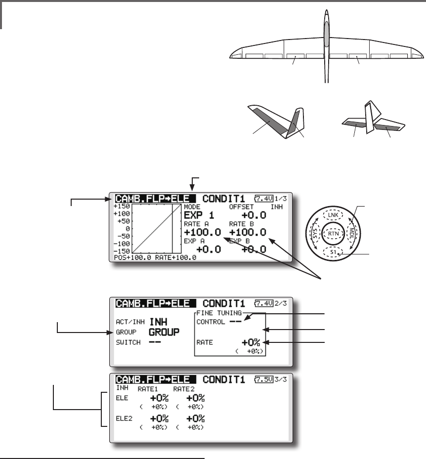
134 <Model Menu (Airplane/Glider Functions) >
●Selectthefunction
nameandreturntothe
precedingscreenby
touchingtheRTNbutton
orpushingtheHome/Exit
button.
<SensorTouch™>
ELEVATOR ELEVATOR 2
V-TAIL
ELEVATOR ELEVATOR 2
AILVATOR
FLP 2
(Camber Flap)
FLP 1
(Camber Flap)
CAMB.FLP to ELE [Correspondingmodeltype]:Airplane/
glider, 2ailerons+1apormore
This mixing is used to correct changes (elevator
direction) generated when the camber aps (speed
aps) are used.
●Theelevatorservosupside/downsideratecanbe
adjusted.Whenthemixingdirectionisreversed
bythelinkage,adjustmentscanbemadeby
changingthemixingratepolarity(+or–).
●Amixingcurvecanbeset.
●MixingduringightcanbeturnedON/OFFby
settingaswitch.(AlwaysONat[--]setting)
●Themixingratecanbene-tunedbysettingaVR.
●Elevatorrate
adjustment
Setting method
●MovethecursortotheACT/INHitemand
touchtheRTNbuttontoswitchtothedata
inputmode.
Turnthetouchsensortotheleftandtouch
theRTNbutton.(ONisdisplayed.)
●Whensettingaswitch,movethecursorto
the[--]itemoftheswitchandtouchtheRTN
buttontocalltheselectionscreen,andthen
selecttheswitchandsetitsONdirection.
(AlwaysONat"--"setting)
(Foradescriptionoftheswitchselection
method,seethedescriptionatthebackof
thismanual.
●Movethecursortotheelevatorservosleft
andrightitemandtouchtheRTNbuttonto
switchtothedatainputmode.Adjustthe
mixingratewiththetouchsensor.
TouchtheRTNbuttontoendadjustmentand
returntothecursolmovemode.
*When the mixing direction is reversed by the linkage,
adjustments can be made by changing the mixing rate
polarity (+ or –).
●WhensettingaVR,movethecursortothe
Finetuning"--"itemandtouchtheRTN
buttontocalltheselectionscreen,andthen
selecttheVR.TheVRoperationmodecan
beselected.
●Amixingcurvecanbeset.
(Foradescriptionofthecurvesetting
method,seethedescriptionatthebackof
thismanual.)
●Overalladjustmentby
RateAandRateB.
(Currently selected condition name)
●Select[CAMB.FLPtoELE]atthemodel
menuandcallthesetupscreenshown
belowbytouchingtheRTNbutton.
●Mixingcurvesetting
*For a description of the curve setting method, see the
description at the back of this manual.
*The display screen is an
example. The actual screen
depends on the model type.
●FinetuningVRsetting
●Adjustmentrate
●Operationmode
●Group/singlemode
switching
(For more information,
refer to the description at
the back of this manual.)
Scrolling
●Movingcursor
●Selectingmode
●Adjustingvalue
●Tonextpage
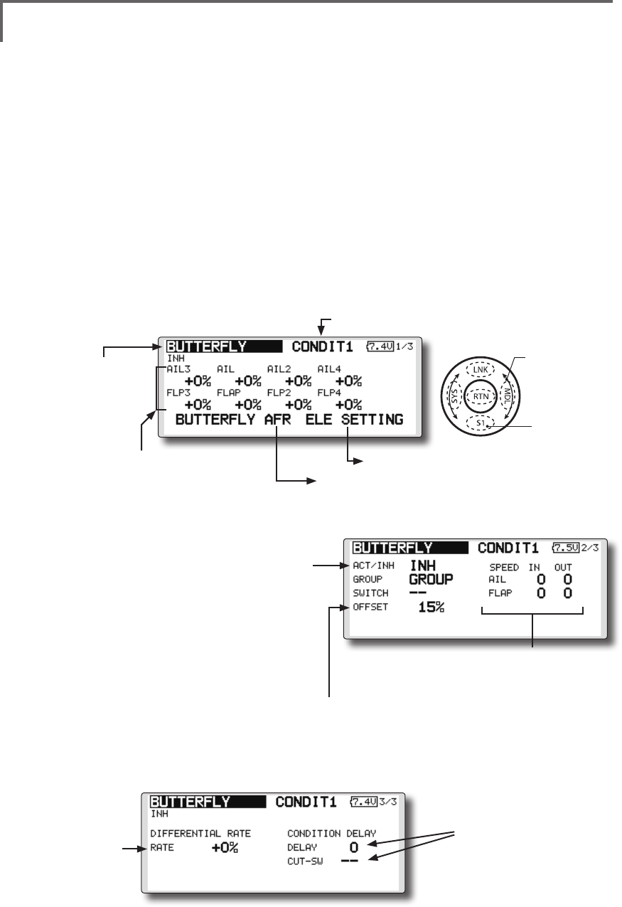
135
<Model Menu (Airplane/Glider Functions) >
●Selectthefunction
nameandreturntothe
precedingscreenby
touchingtheRTNbutton
orpushingtheHome/Exit
button.
<SensorTouch™>
BUTTERFLY [Correspondingmodeltype]:Glider,2aileronsormore
This function allows powerful brake operation
by simultaneously raising the left and right
ailerons and lowering the flaps (camber flap,
brake ap).
This setting will allow the ailerons to be raised
while the flaps are simultaneously lowered.
Butterfly (crow) produces an extremely efficient
landing configuration by accomplishing the
following:
1.Slowtheaircraft’svelocity.
2.Providewashoutatthewingtipstoreduce
thetendencytotipstall.
3.Createmorelifttowardthecenterofthe
wingallowingittoyataslowerspeed
●MixingduringightcanbeturnedON/OFFby
settingaswitch.(AlwaysONat[--]setting)
●Thebutteryoperationreferencepointcanbe
offset.WhentheRTNbuttonistouchedwith
theoffsetitemselectedwhenoperatedtothe
positiontobechanged,thereferencepointis
offset.Ifthereferencepointisoffsettoomuch,
unexpectedoperationmaybeperformed.
●Theaileronsandapsoperationspeedcanbe
adjusted.(INside/OUTside)
●Adelaycanbesetforeachcondition.Acut
switchwhichcanturnOFFthedelayfunctioncan
alsobeset.
●Thedifferentialratecanbeadjusted.
*When servo binding occurs when setting the ailerons and
aps in buttery mixing, use the AFR function to adjust the
rudder angle.
●Whenoffsettingthebutterfly operation
referencepoint,operatetothepointyou
wanttochangeandthenpresstheEDIT
buttonfor1second."INITIALIZEELEVATOR
CURVE?"isdisplayed.Pleasechoosewhether
toinitializebyYES,ornottoinitializebyNO.
●Differentialrate
adjustment
●Toelevatorcorrectionsetupscreen
●CallstheButteryAFR(D/R)setupscreen
(For a description of the setting method, see the description
at the back of this manual.)
●Aileronandapservosspeedsetting
(For a description of the setting method, see the
description at the back of this manual.)
●Conditiondelaysetting
andcutswitchsetting
(For a description of the setting
method, see the description at
the back of this manual.)
● SelecttheMixingRateAILandFLP
boxandtouchtheRTNbuttonto
switchtothedatainputmode.
Adjustthemixingrates.
TouchtheRTNbuttontoend
adjustmentandreturntothecursol
movemode.
(Currently selected condition name)
●Select[BUTTERFLY]atthemodelmenu
andcallthesetupscreenshown
belowbytouchingtheRTNbutton.
*The display screen is an example. The actual
screen depends on the model type.
●Whenusingthisfunction,movethecursorto
the[ACT/INH]itemandtouchtheRTNbutton
toswitchtothedatainputmode.Turnthe
touchsensortotheleft andtouchtheRTN
button.(ONisdisplayed.)
●Group/singlemodeswitching
(For more information, see the description at the back of this
manual.)
●Whensettingaswitch,selecttheSWITCH[--]
boxandtouchtheRTNbuttontoswitchto
thedatainputmode.PresstheEDITbuttonto
calltheselectionscreen,andthenselectthe
switchandsetitsONdirection.
Scrolling
●Movingcursor
●Adjustingvalue
●Tonextpage
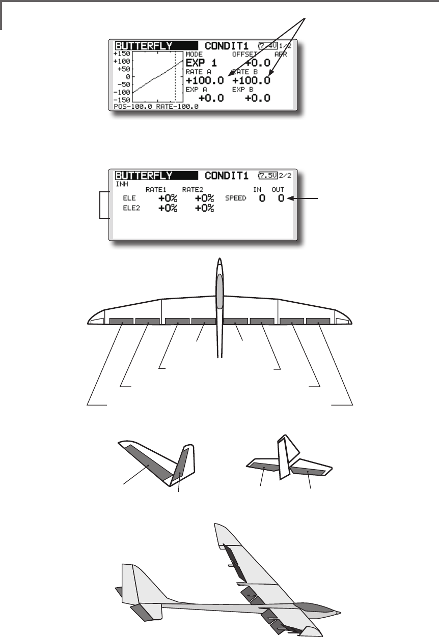
136 <Model Menu (Airplane/Glider Functions) >
AIL 3
(Chip Aileron) AIL 4
(Chip Aileron)
AIL1
(Main Aileron) AIL 2
(Main Aileron)
FLP 2
(Camber Flap)
FLP 1
(Camber Flap)
ELEVATOR ELEVATOR 2
V-TAIL
ELEVATOR ELEVATOR 2
AILVATOR
FLP 3
(Brake Flap) FLP 4
(Brake Flap)
(Elevatorcorrectionratesetupscreen)
●Servospeedsetting
(For a description of the setting
method, see the description at
the back of this manual.)
●Overalladjustmentby
RateAandRateB
●Elevatorrate
adjustment
●Mixingcurvesetting
*For a description of the curve setting method, see the
description at the back of this manual.
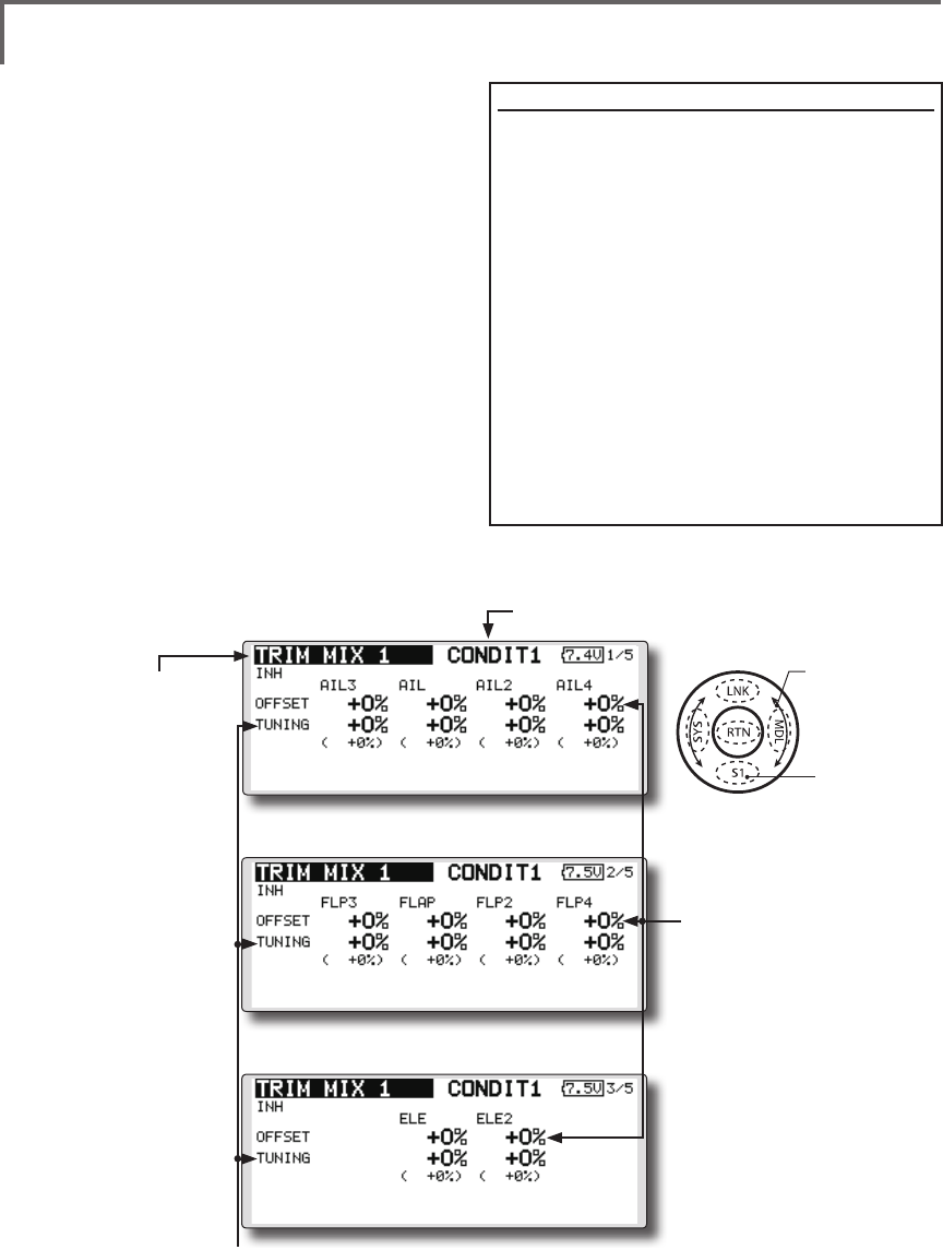
137
<Model Menu (Airplane/Glider Functions) >
●Selectthefunction
nameandreturntothe
precedingscreenby
touchingtheRTNbutton
orpushingtheHome/Exit
button.
<SensorTouch™>
TRIM MIX 1/2 [Correspondingmodeltype]:Glider,2aileronsormore
These functions call the ailerons, elevators, and
aps (camber aps, brake aps) trim offset rates
preset according to the ight state.
The amount of ailerons, elevator, and flaps
(camber ap, brake ap) trim offset can be set to
a switch.
As an example Trim Mix 1 can be set up for
launching, with speed aps and ailerons dropped,
and a slight amount of up elevator. Trim mix
2 can be used for high speed flying, with both
ailerons and speed aps reexed slightly, and a bit
of down elevator.
The trim functions can be activated during
ight by setting a switch. To prevent sudden trim
changes when switching ight conditions, a delay
can be set to provide a smooth transition between
the two. Trim Mix 2 will have priority over Trim
Mix 1.
●WhenanetuningVRissetonthenextpage,theaileronsapsandelevators
trimratescanbeadjusted.
MovethecursortothecorrespondingsettingitemandtouchtheRTNbuttonto
switchtothedatainputmode.adjusttheratewiththetouchsensor.
TouchtheRTNbuttontoendadjustmentandreturntothecursolmovemode.
●Theailerons,flaps,and
elevatorsoffsetratecan
beadjusted.
Movethecursortothe
correspondingsetting
itemandtouchtheRTN
buttontoswitchtothe
datainputmode.Adjust
theratewiththetouch
sensor.
TouchtheRTNbutton
toendadjustmentand
returntothecursolmove
mode.
Example
1.MovetotheACT/INHitem andtouchtheRTN
buttontoswitchtothedatainputmode.
Setthetrimmixfunctionto[ON].
*When separating the settings for each condition, move to
the [GROUP] item and set it to [Single].
2.SelecttheON/OFFswitch.
3.Selectthe[Manual]or[Auto]mode.
Inthe[Auto]mode,alsoselect anautoSW.This
switchcanbelinkedtoastick,etc.
<Speed>
In:TheoperationspeedatswitchONcanbeset.
Out:ThereturnspeedatswitchOFFcanbeset.
<FineTuning>
TheoffsetratecanbevariedintheFine Tuning
numericrangesetatscreen[5/5]byVR,etc.
selection.
<ConditionDelay>
Whenightconditionsareset,theoperationspeed
canbesetforeachcondition.Conditiondelay
operationcanbeinterruptedandeachrudder
quicklyreturnedtoitsoriginalpositionbyselectinga
cutswitch.
(Currently selected condition name)
●Select[TRIMMIX1or2]atthemodel
menuandcallthesetupscreenshown
belowbytouchingtheRTNbutton.
*The display screen is an example. The actual screen depends
on the model type.
Scrolling
●Movingcursor
●Adjustingvalue
●Tonextpage
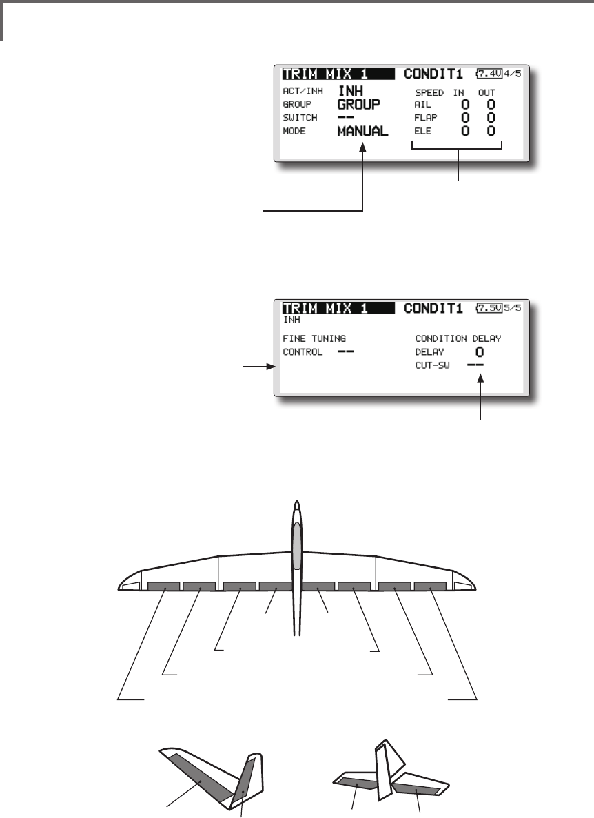
138 <Model Menu (Airplane/Glider Functions) >
●Whenusingthisfunction,movethecursor
tothe[ACT/INH]itemandtouchtheRTN
buttontoswitchtothedatainputmode.
Turnthetouchsensortotheleftand
touchtheRTNbutton.(ONisdisplayed.)
●Group/singlemodeswitching
(For more information, see the description at the back of
this manual.)
●WhenusingafinetuningVR,move
thecursortothisitemandtouch
theRTNbuttontocalltheselection
screen.
SelecttheVRandtouchtheRTN
button. ●Conditiondelaysetting(fora
descriptionofthesettingmethod,
seethedescriptionatthebackof
thismanual)andcutswitchsetting.
●Ailerons,aps,anelevatorsservo
speedsetting
(For a description of the setting method, see
the description at the back of this manual.)
●Manual/Automodeselection
Manual:SwitchesthefunctionON/OFFbyswitch
Auto:Trimmixfunctioncallcanbelinkedtoastick,
etc.Astickswitch,etc.separatefromthefunction
ON/OFFswitchisset.
AIL 3
(Chip Aileron) AIL 4
(Chip Aileron)
AIL1
(Main Aileron) AIL 2
(Main Aileron)
FLP 2
(Camber Flap)
FLP 1
(Camber Flap)
ELEVATOR ELEVATOR 2
V-TAIL
ELEVATOR ELEVATOR 2
AILVATOR
FLP 3
(Brake Flap) FLP 4
(Brake Flap)
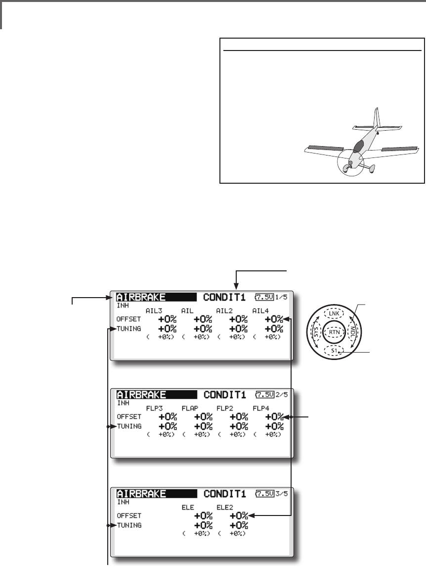
139
<Model Menu (Airplane/Glider Functions) >
●Selectthefunction
nameandreturntothe
precedingscreenby
touchingtheRTNbutton
orpushingtheHome/Exit
button.
<SensorTouch™>
AIRBRAKE [Correspondingmodeltype]:Airplane,general
This function is used when an air brake is
necessary when landing or diving, etc.
The preset elevators and flaps (camber flap,
brake flap) offset amount can be activated by a
switch.
The offset amount of the aileron, elevator, and
flap servos can be adjusted as needed. Also the
speed of the aileron, elevator, and ap servos can
be adjusted. (IN side/OUT side) A delay can be set
for each condition, and a Cut switch which will
turn OFF the delay can be chosen. Trim amounts
can be fine-tuned by setting a VR You can also
set the Auto Mode, which will link Airbrake to a
stick, switch, or dial. A separate stick switch or
dial can also be set as the ON/OFF switch.
Setting example for F3A and other aperon specications
(When2aileronsmodeltypeselected)
Offsetrate:
AIL:[-35~-45%],AIL2:[-35~-45%],ELE:[+5~7%]
Note: The input numerics are examples. Adjust the travel to
match the aircraft.
Modesetting:
ACT:[ON]
Group:[Single]
Switch:[SW-C]
Mode:[Manual]
●WhenanetuningVRissetonthenextpage,theailerons',aps',andelevators'
trimratescanbeadjusted.
MovethecursortothecorrespondingsettingitemandtouchtheRTNbuttonto
switchtothedatainputmode.Adjusttheratewiththetouchsensor.
TouchtheRTNbuttontoendadjustmentandreturntothecursolmovemode.
●Theailerons,flaps,and
elevatorsoffsetratecan
beadjusted.
Movethecursortothe
correspondingsetting
itemandtouchtheRTN
buttontoswitchtothe
datainputmode.Adjust
theratewiththetouch
sensor.
TouchtheRTNbutton
toendadjustmentand
returntothecursolmove
mode.
(Currently selected condition name)
●Select[AIRBRAKE]atthemodelmenuandcallthe
setupscreenshownbelowbytouchingtheRTN
button.
*The display screen is an example. The actual
screen depends on the model type.
Scrolling
●Movingcursor
●Adjustingvalue
●Tonextpage
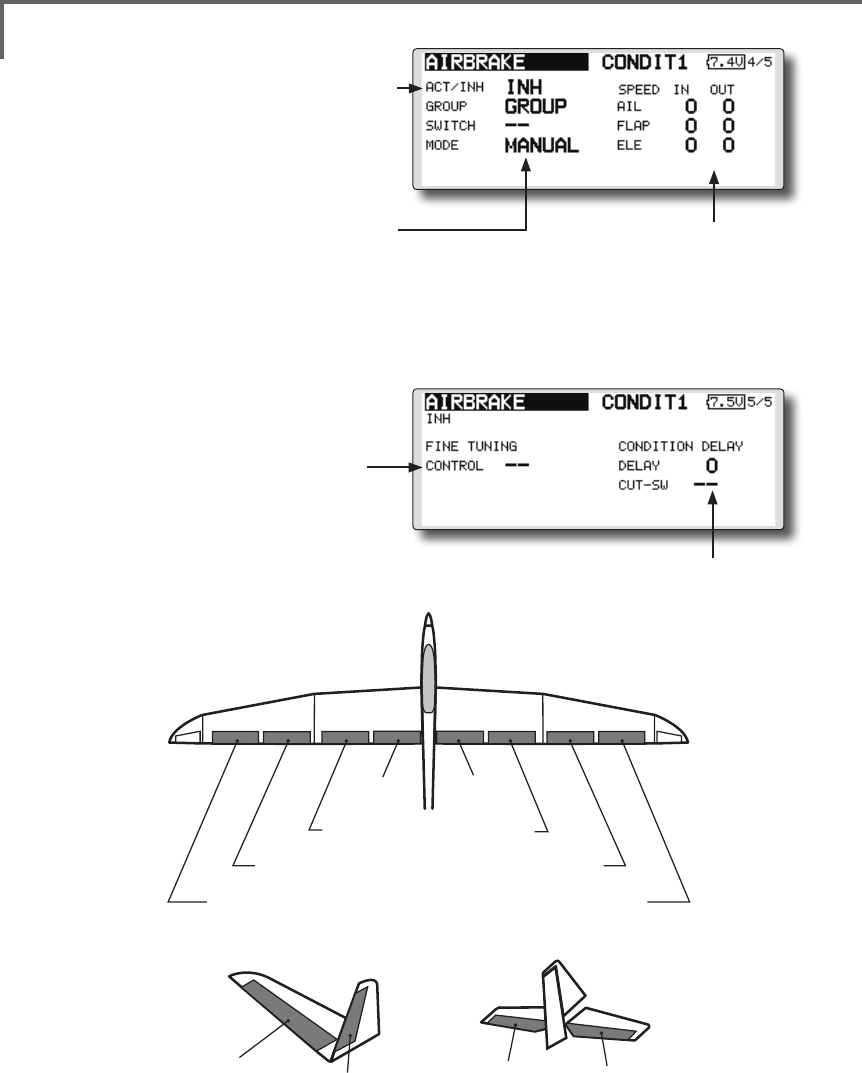
140 <Model Menu (Airplane/Glider Functions) >
●Whenusingthisfunction,movethecursor
tothe[ACT/INH]itemandturnthetouch
sensortotheleftandtouchtheRTN
button.(ONisdisplayed.)
●Group/singlemodeswitching
(For more information, see the description at the back of
this manual.)
●WhenusingafinetuningVR,move
thecursortothissettingitemand
presstheEDITbuttontocallthe
selectionscreen.
SelecttheVRandtouchtheRTN
button. ●Conditiondelaysetting(fora
descriptionofthesettingmethod,
seethedescriptionatthebackof
thismanual)andcutswitchsetting.
●Ailerons,aps,anelevatorsservo
speedsetting
(For a description of the setting method, see
the description at the back of this manual.)
●Manual/Automodeselection
Manual:SwitchesthefunctionON/OFFbyswitch
Auto:Trimmixfunctioncallcanbelinkedtoastick,
etc.Astickswitch,etc.separatefromthefunction
ON/OFFswitchisset.
AIL 3
(Chip Aileron) AIL 4
(Chip Aileron)
AIL1
(Main Aileron) AIL 2
(Main Aileron)
FLP 2
(Camber Flap)
FLP 1
(Camber Flap)
ELEVATOR ELEVATOR 2
V-TAIL
ELEVATOR ELEVATOR 2
AILVATOR
FLP 3
(Brake Flap) FLP 4
(Brake Flap)
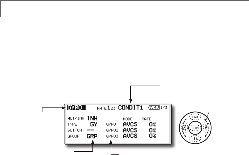
141
<Model Menu (Airplane/Glider Functions) >
●Selectthefunction
nameandreturntothe
precedingscreenby
touchingtheRTNbutton
orpushingtheHome/Exit
button.
<SensorTouch™>
GYRO [Correspondingmodeltype]:Airplane/glider,general
This function is used when a GYA Series gyro
is used to stabilize the aircraft's attitude. The
sensitivity and operation mode (Normal mode/GY
mode) can be switched with a switch.
●Threerates(Rate1/Rate2/Rate3)canbe
switched.
●Upto3axes(Gyro/Gyro2/Gyro3)canbe
simultaneouslycontrolled.
*Initial setting does not assign a sensitivity channel. Use the
Function menu of the Linkage Menu to assign the sensitivity
channel (Gyro/Gyro2/Gyro3) used to a vacant channel
beforehand.
Set [Control] and [Trim] other than Function to [--].
●Theoperationmode(AVCS/NOR)andsensitivity
ofthe3axesGyro/Gyro2/Gyro3canbeset.
●Group/singlemode
switching
(For more information, see the
description at the back of this
manual.)
●Threerates(Rate1/Rate2/Rate3)canbeused.
Movethecursortothe[RATE]itemandtouchtheRTNbuttontoswitch
tothedatainputmode.Adjusttheratebyscrollingthetouchsensor.
●Whenusingthisfunction,movethecursortothe[ACT]itemandtouch
theRTNbuttontoswitchtothedatainputmode.Turnthetouchsensor
totheleftandtouchtheRTNbutton.
●WhenaFutabaGYAgyroisused,when[GY]typeisselected,the
sensitivitysetvalueisdirectlyreadinboththeAVCSandNORMmodes.
●Whensettingaswitch, movethecursortotheSWITCHitemandpress
theEDITbuttontocalltheselectionscreen,andthenselecttheswitch
andsetitsONdirection.
(Foradescriptionoftheswitchselectionmethod,seethedescriptionat
theendofthismanual.)
(Currently selected condition name)
●Select[GYRO]atthemodelmenuand
callthesetupscreenshownbelowby
touchingtheRTNbutton.
Scrolling
●Movingcursor
●Selectingmode
●Adjustingvalue
●Tonextpage
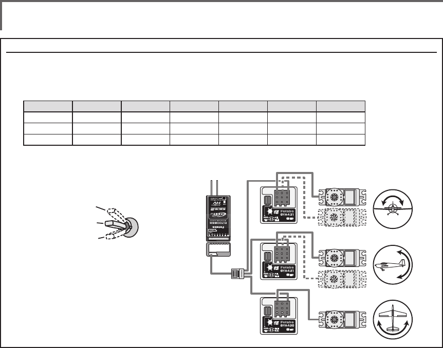
142 <Model Menu (Airplane/Glider Functions) >
(Example) Setting three axis using a GYA430 and GYA431 (2)
●Wingtype:Aileron2servosmountedfuselageselected
●Set5CH → GYRO(GYA431AIL),7CH → GYRO2(GYA431ELE),8CH → GYRO3(GYA430RUD),Control and Trim → NULL :
attheFunctionmenuoftheLinkagemenu.
●GYROsettingoftheModelmenu.
*Set so that Rate 1 is turned on at the back position of switch E
and Rate 3 is turned ON at the front position. Since switch E is
turned OFF at the center, Rate 2 remains [INH].
Rudder servo
Elevator servo
GYA430
GYA431
GYA431
Aileron servo
S.BUS2 port
R7008SB
GAIN 0%
AVCS
NORMAL
When AVCS is used we
recommend that the
sensitivity CH be set to
the 3-position.
Rate ACT Type Switch GYRO GYRO 2 GYRO 3
1 OFF/ON GY SE AVCS : 60% AVCS : 60% AVCS : 60%
2 INH
3 ON/OFF GY SE NORM : 60% NORM : 60% NORM : 60%
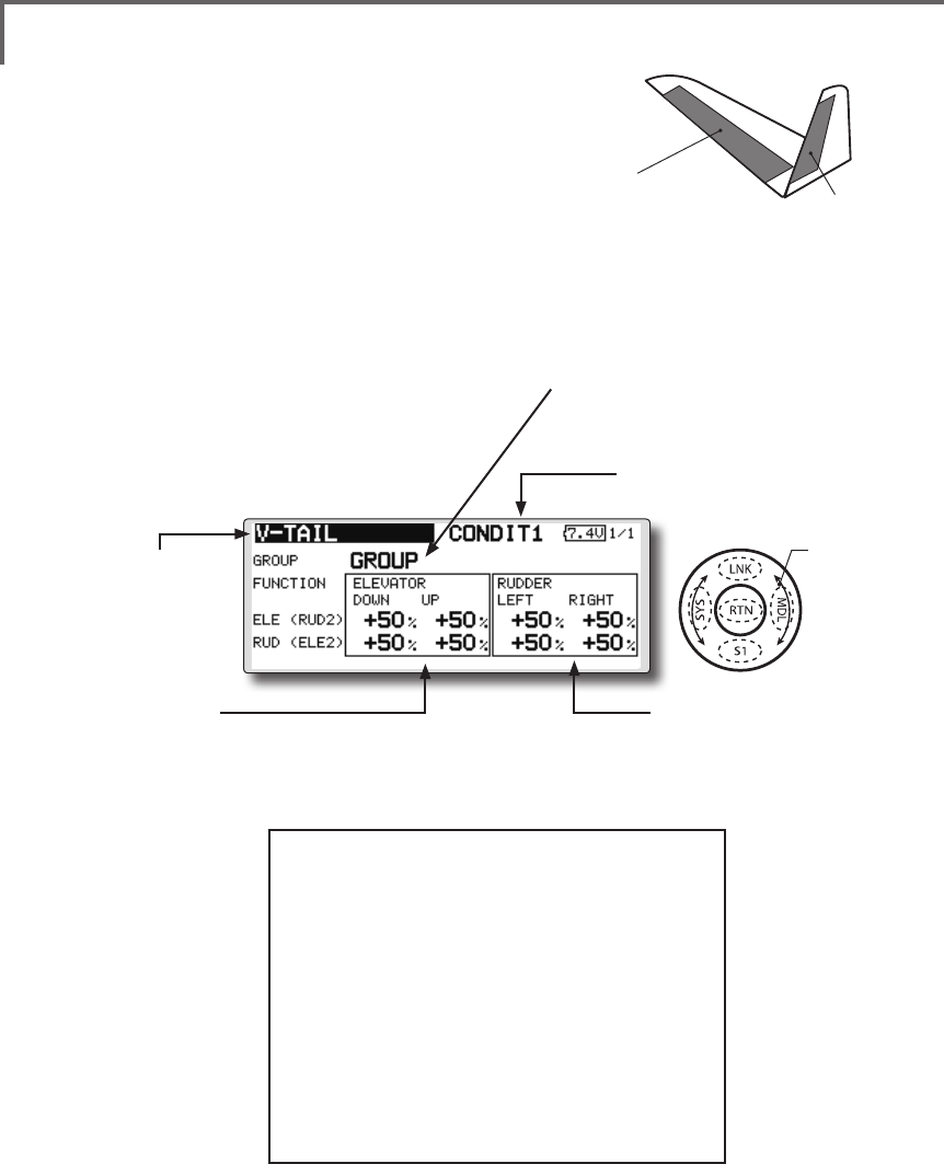
143
<Model Menu (Airplane/Glider Functions) >
●Selectthefunction
nameandreturntothe
precedingscreenby
touchingtheRTNbutton
orpushingtheHome/Exit
button.
<SensorTouch™>
ELEVATOR
(RUDDER 2) RUDDER
(ELEVATOR 2)
V-TAIL [Correspondingmodeltype]:Airplane/glider,V-tail
This function let’s you adjust for left and right
rudder angle changes at elevator and rudder
operation of a V-tail airplane.
V-tail is when 2 servos are used together to
control rudder movement as elevators. In addition
to each rudder side moving up and down together,
each side moves in opposite directions when moving
as elevators. On a V-tail, this is also known as a
ruddervator, as they can serve the same purpose.
(Rudderfunction)
Leftandrighttravel
adjustmentatCH1and
CH2rudderoperation
●Group/singlemodeswitching
(For more information, see the description
at the back of this manual.)
(Elevatorfunction)
Upanddowntraveladjustmentat
CH1andCH2elevatoroperation
(Currently selected condition name)
●Select[V-TAIL]atthemodel
menuandcallthesetupscreen
shownbelowbytouchingthe
RTNbutton.
●Traveladjustment
Movethecursortotheitemyouwantto
adjustandtouchtheRTNbuttontoswitch
tothedatainputmode.
Adjusttheratebyscrollingthetouchsensor.
TouchtheRTNbuttontoendadjustment
andreturntothecursolmovemode.
*If the mixing direction is reversed by the linkage,
adjustments can be made by changing the mixing rate
polarity (+ or -).
*If a large value of travel is specied, when the sticks are
moved at the same time, the controls may bind or run out
of travel. Decrease the travel until no binding occurs.
Scrolling
●Movingcursor
●Selectingmode
●Adjustingvalue
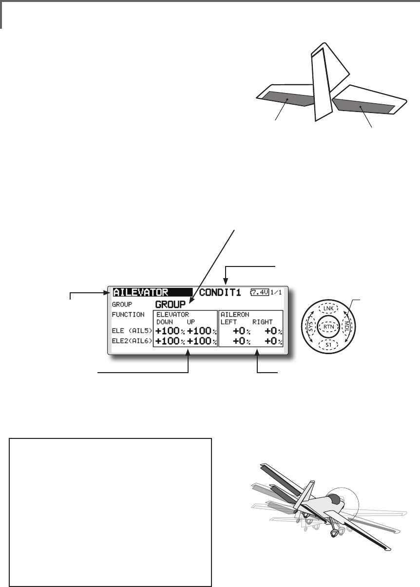
144 <Model Menu (Airplane/Glider Functions) >
●Selectthefunction
nameandreturntothe
precedingscreenby
touchingtheRTNbutton
orpushingtheHome/Exit
button.
<SensorTouch™>
ELEVATOR ELEVATOR 2
(AILERON 5) (AILERON 6)
AILEVATOR [Correspondingmodeltype]:Airplane/glider,V-Tail
(Effective only when 2 servos used at the elevators)
This function improves the operating
performance of the roll axis by operating the
elevators as ailerons.
Ailevator is where each elevator in a standard
(conventional) or v-tail moves independently, like
ailerons on a wing. In addition to each elevator side
moving up and down together, each side moves in
opposite directions when moving as an ailevator.
On a V-tail, this is also known as a ruddervator,
as they can serve the same purpose. Typically,
both ailevator and ailerons are coupled together to
maximize roll performance, especially on larger
wingspan planes.
Note:SelectailevatorastheModeltypeatthe
Modeltypescreen.Thischangestheoutput
channel.ChecktheFunctionmenu.
(Aileronfunction)
●Whentheelevatorsareused
asailerons,ailerontravelof
theleftandrightelevators
canbeadjusted.
(Elevatorfunction)
●Theupanddownrateoftheleft
andrightelevatorswhenthe
elevatorstickismanipulatedcan
beindividuallyadjusted.
●Group/singlemodeswitching
(For more information, see the description
at the back of this manual.)
(Currently selected condition name)
●Select[AILEVATOR]atthe
modelmenuandcallthe
setupscreenshownbelowby
touchingtheRTNbutton.
●Traveladjustment
Movethecursortotheitemyouwantto
adjustandtouchtheRTNbuttontoswitch
tothedatainputmode.
Adjusttheratebyscrollingthetouchsensor.
TouchtheRTNbuttontoendadjustment
andreturntothecursolmovemode.
*If the mixing direction is reversed by the linkage,
adjustments can be made by changing the mixing rate
polarity (+ or -).
*If a large value of travel is specied, when the sticks are
moved at the same time, the controls may bind or run out
of travel. Decrease the travel until no binding occurs.
Scrolling
●Movingcursor
●Selectingmode
●Adjustingvalue
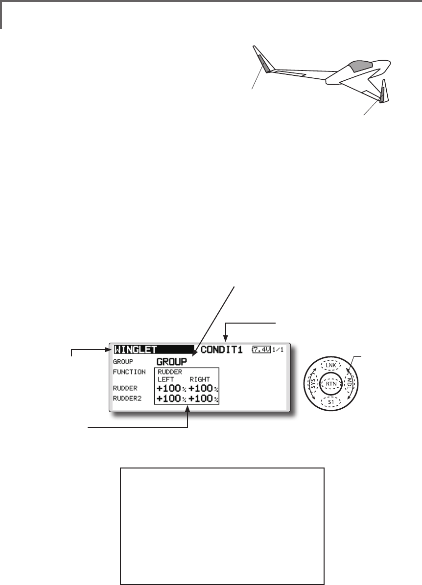
145
<Model Menu (Airplane/Glider Functions) >
●Selectthefunction
nameandreturntothe
precedingscreenby
touchingtheRTNbutton
orpushingtheHome/Exit
button.
<SensorTouch™>
RUDDER 1
Winglet
at Flying wing
( )
RUDDER 2
Winglet
at Flying wing
( )
WINGLET [Correspondingmodeltype]:Airplane/glider,winglet
This function adjusts the left and right rudder
angles of airplanes with winglets.
Winglets are used to improve the efficiency of
aircraft lowering the lift-induced drag caused by
wingtip vortices. The winglet is a vertical or angled
extension at the tips of each wing.
Winglets work by increasing the effective aspect
ratio wing without adding greatly to the structural
stress and hence necessary weight of its structure
- an extension of wing span would also permit
lowering of induced drag, though it would cause
parasitic drag and would require boosting the
strength of the wing and hence its weight - there
would come a point at which no overall useful
saving would be made. A winglet helps to solve this
by effectively increasing the aspect ratio without
adding to the span of the wing.
(Rudder1/2)
●Thetravelatrudderstickleftandrightoperationcan
beindividuallyset.
●Group/singlemodeswitching
(For more information, see the description
at the back of this manual.)
(Currently selected condition name)
●Select[WINGLET]atthemodel
menuandcallthesetupscreen
shownbelowbytouchingthe
RTNbutton.
●Traveladjustment
Movethecursortotheitemyouwantto
adjustandtouchtheRTNbuttontoswitch
tothedatainputmode.
Adjusttheratebyscrollingthetouchsensor.
TouchtheRTNbuttontoendadjustment
andreturntothecursolmovemode.
*If the mixing direction is reversed by the linkage,
adjustments can be made by changing the mixing rate
polarity (+ or -).
Scrolling
●Movingcursor
●Selectingmode
●Adjustingvalue
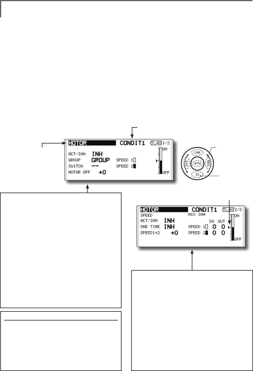
146 <Model Menu (Airplane/Glider Functions) >
●Selectthefunction
nameandreturntothe
precedingscreenby
touchingtheRTNbutton
orpushingtheHome/Exit
button.
<SensorTouch™>
MOTOR [Correspondingmodeltype]:EPglider,general
This function lets you set the operation speed
when the motor of a F5B or other EP glider is
started by switch. The operation speed can be set
in 2 ranges of slow speed flight and high speed
ight (Speed 1/Speed 2). This function can also be
operated as a safety function by setting 2 switches.
●Theinsideandoutsideoperatingspeedscanbe
adjustedindependentlyin2ranges(Speed1/
Speed2).
●Theboundarybetweenthe2rangescanbeset.
(Fromspeed1tospeed2)
●Thesetoperationspeedoperationcanbe
activatedatinitialoperationonly.(1time
operation)However,operationcanberepeated
●Movethecursorby
setswitchorVR.
bysettingtheswitchtoOFFbeforeoperationis
nished.Whenyouwanttoreset1timeoperation,
settheACT/INHitemto[INH]andthenresetitto
[ON].
●Themotor(CH3)iscontrolledbySW-G.(Initial
setting)Whenchangingtheswitchorstickwhich
controlsthemotor,rstchangeFunctionofthe
LinkageMenu.
Note: When using this function, always check initial
operation with the propeller removed.
●Whenusingthisfunction,movethecursor
tothe[ACT/INH]itemandtouchtheRTN
buttontoswitchtothedatainputmode.
Turnthetouchsensortotheleftandtouch
theRTNbutton.
●Whenyouwanttosetthe"Onetimemode",
movethecursortothe[ONETIME]itemand
turnthetouchsensortotheleftandtouch
theRTNbutton.
●Speed1to2
Thespeed1andspeed2regionboundary
canbechanged,
●Operationspeedadjustment
Thespeedwhenspeed1andspeed2are
ON(In)andOFF(Out)canbeadjusted.
●Whenusingthisfunction,movethecursor
tothe[ACT/INH]itemandtouchtheRTN
buttontoswitchtothedatainputmode.
Turnthetouchsensortotheleftandtouch
theRTNbutton.
●Group/singlemodeswitching
(Formoreinformation,seethedescription
atthebackofthismanual.)
●Switch
Aswitchthatturnsthefunctionitself
ON/OFFcanbeselected.
●Motoroffposition
PresstheEDITbuttonfor1secondwhen
[SW-G]isinthemotorOFFpositionyouwant
toset.Thedirectionofthemotorswitchis
memorized.ThescreengraphdisplayOFF
directionalsochanges.
Notes
●FirstdecidethemotorOFFdirection,andthen
setthespeed.Whenyouwanttoresetthe
motorOFFdirection,alsoresetthespeed.
●WerecommendthatmotorOFFbesetin
combinationwithF/S.
●Setthebasicoperationdirectionwiththereverse
functiontomatchtheESCused.
●AlwayssetthemotorOFFposition.
(Currently selected condition name)
●Select[MOTOR]atthemodelmenu
andcallthesetupscreenshown
belowbytouchingtheRTNbutton.
Scrolling
●Movingcursor
●Selectingmode
●Adjustingvalue
●Tonextpage
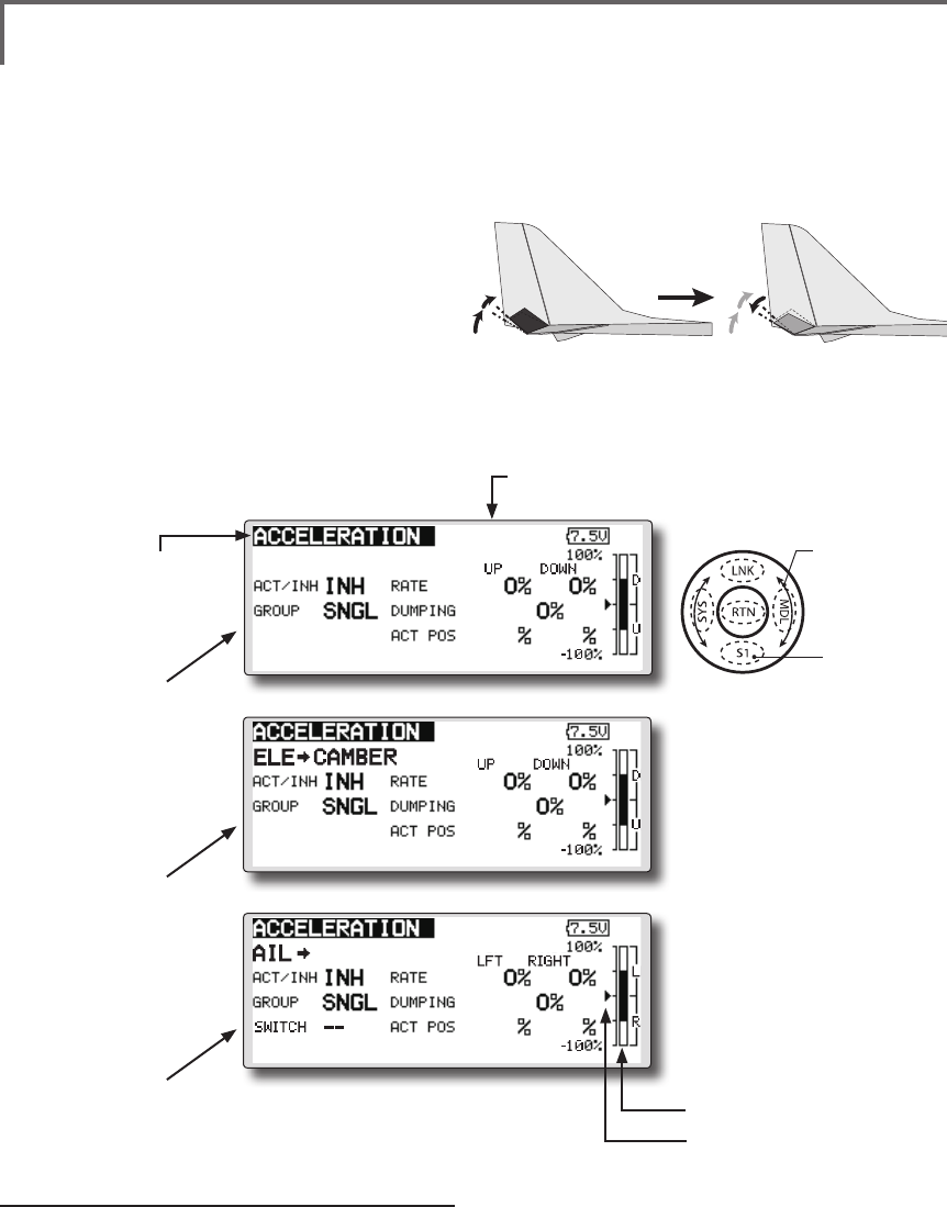
147
<Model Menu (Airplane/Glider Functions) >
●Selectthefunction
nameandreturntothe
precedingscreenby
touchingtheRTNbutton
orpushingtheHome/Exit
button.
<SensorTouch™>
[Correspondingmodeltype]:Glider,general
CONDIT1
1/3
ELEVATOR
-50 +50
ACCELERATION
●1/3Elevatorsetting
●2/3Elevator →Cambersetting
●3/3Aileron →Ruddersetting
Setting method
●Accelerationratesetting(Rate)
●Thereturntimeafteroperation(Dumping)
canbeset.
●Theoperationpointatacceleration
anddecelerationcanbeset.Whenan
operationpointisexceeded,accelerationis
performed.
(Currently selected condition name)
●Select[ACCELERATION]atthemodel
menuandcallthesetupscreenshown
belowbytouchingtheRTNbutton.
●Actposition
●Currentposition
Acceleration setting can be performed at
elevator, ELE to Camber and AIL to RUD.(Glider
and EP glider only)
●Thissettingisdividedintoelevatorsettingand
cambersetting.Thesettingmethodisthesame.
●Cambersettingsetstheaccelerationfunctionfor
ELEtocambermixing.Settingisnotperformed
whenELEtocambermixingisINH.
●Theaccelerationfunctioncanbesetforboththe
upsideanddownside.
●FunctionON/OFFswitchsettingisperformedforAIL
toRUDsettingonly.
●AILtoRUDsettingisacceleration
functionsettingforAILtoRUDmixing.Itisnot
performedwhenAILtoRUDmixingisINH.
CONDIT1
2/3
-50 +50
CONDIT1
3/3
-50 +50
RUD
Scrolling
●Movingcursor
●Selectingmode
●Adjustingvalue
●Tonextpage
Note:Whenusingtheaccelerationfuntion,
sincetheservostrokeislarge,makeyour
settingssothereisnobindingofyourlinkage.
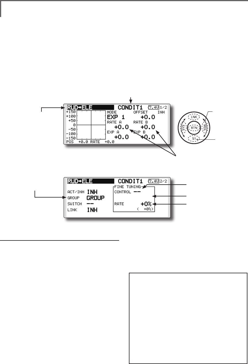
148 <Model Menu (Airplane/Glider Functions) >
●Selectthefunction
nameandreturntothe
precedingscreenby
touchingtheRTNbutton
orpushingtheHome/Exit
button.
<SensorTouch™>
RUD to ELE [Correspondingmodeltype]:Airplane,general
This function is used when you want to mix
elevator operation with rudder operation. It is used
to correct undesirable tendencies when rudder is
applied in roll maneuvers, knife edge, etc. of stunt
planes.
●Amixingcurvecanbeset.
●MixingduringightcanbeturnedON/OFFby
settingaswitch.(AlwaysONat[--]setting)
●Linkcanbeset:Linksthismixingtoothermixings.
●Themixingratecanbene-tunedbysettingaVR.
(Finetuning)
Setting method
●MovethecursortotheACT/INHitemand
touchtheRTNbuttontoswitchtothedata
inputmode.Turnthetouchsensortotheleft
andtouchtheRTNbutton.(ONisdisplayed.)
●Whensettingaswitch,movethecursorto
the[--]itemoftheswitchandtouchtheRTN
buttontocalltheselectionscreen,andthen
selecttheswitchandsetitsONdirection.
(AlwaysONat"--"setting)
(Foradescriptionoftheswitchselection
method,seethedescriptionatthebackof
thismanual.)
●WhensettingaVR,movethecursortothe
FineTuning"--"itemandtouchtheRTN
buttontocalltheselectionscreen,andthen
selecttheVR.Thenetuningratecanbeset.
TheVRoperationmodecanalsobeset.
●Mixingcurvesetting
*For a description of the curve setting method, see the
description at the back of this manual.
●Left/rightoverall
adjustmentatrateA
andrateB
(Currently selected condition name)
●Select[RUDtoELE]atthemodel
menuandcallthesetupscreen
shownbelowbytouchingthe
RTNbutton.
●Group/singlemode
switching
(For more information, refer
to the description at the
back of this manual.)
*The display screen is an
example. The actual screen
depends on the model type.
●FinetuningVRsetting
●Adjustmentrate
●Operationmode
[FinetuningVRoperationmode]
[LIN.] Mixingrate0%atcenterofVR.
WhentheVRisturnedclockwiseand
counterclockwise,themixingrate
increasesanddecreases,respectively.
[ATL+]Mixingrate0%atleftendofVR.
WhentheVRisturned,themixingrate
increases.
[ATL-] Mixingrate0%atrightend ofVR.
WhentheVRisturned,themixingrate
increases.
[SYM.]WhentheVRisturnedtotheleftor
rightoftheneutralposition,themixing
rateincreases.
(ForadescriptionofthenetuningVRsetting
method,seethedescriptionatthebackof
thismanual.)
●WhensettingLink,movethecursortotheLink
itemandtouchtheRTNbuttontoswitchto
thedatainputmode.SetittoON.
Scrolling
●Movingcursor
●Selectingmode
●Adjustingvalue
●Tonextpage
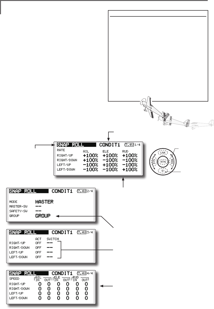
149
<Model Menu (Airplane/Glider Functions) >
●Selectthefunction
nameandreturntothe
precedingscreenby
touchingtheRTNbutton
orpushingtheHome/Exit
button.
<SensorTouch™>
SNAP ROLL [Correspondingmodeltype]:Airplane,general
This function selects the switch and rate
adjustment of each rudder, (ailerons, elevators, or
aps) when a snap roll is performed.
●Foursnaprolldirectionscanbeset.(Right/up,
right/down,left/up,left/down)
●Operationmode:When[Master]modeisselected,
theSnapRollfunctionisturnedON/OFFbymaster
switchinthestateinwhichthedirectionswitch
wasswitchedtothedirectioninwhichyouwant
tosnaproll.When[Single]modeisselected,snap
rollineachdirectioncanbeexecutedbymeans
ofindependentswitches.
●Asafetyswitchcanbeset.Asasafetymeasure,
theswitchcanbesetsothatsnaprollisnot
executedwhen,forinstance,thelanding
gearislowered,eveniftheswitchisturnedon
accidentally.Thesnaprollswitchisactivatedonly
whenthesafetyswitchisON.
●Theoperationspeedoftheaileron,elevator,and
apservoscanbeadjustedforeachsnaproll
direction.(Inside/outside)
(Example) Setting example for F3A
●Mode:[Master]
●SafetySW:[SW-G](Safetymeasure)
●MasterSW:[SW-H](Mainswitchfor
executingsnaproll)
●Directionswitches:
*The snap roll up side left and right and down side left and right
direction switches are selected here.
Right/Up:OFF[SW-D]
Right/Down:OFF[SW-D]
Left/Up:OFF[SW-A]
Left/Down:OFF[SW-A]
●Speedadjustment
Theoperationspeedofeachcontrol
surfacewhenthesnapswitchisONcan
bechangedandsnaprollexecutedby
stickwhilethereisswitchoperationcanbe
performed.
●Rateadjustment
1.Movethecursortotheitemyouwantto
adjustandtouchtheRTNbuttontoswitch
tothedatainputmode.
2.Adjustratebyscrollingthetouchsensor.
3.TouchtheRTNbuttontoendadjustment
andreturntothecursolmovemode.
●Group/singlemodeswitching
(For more information, see the description at the back of
this manual.)
●Directionswitches
●Adjustmentoftheservospeedofeach
rudder
(For a description of the setting method, see the
description at the back of this manual.)
(Currently selected condition name)
●Select[SNAPROLL]atthemodelmenu
andcallthesetupscreenshown
belowbytouchingtheRTNbutton.
Scrolling
●Movingcursor
●Selectingmode
●Adjustingvalue
●Tonextpage
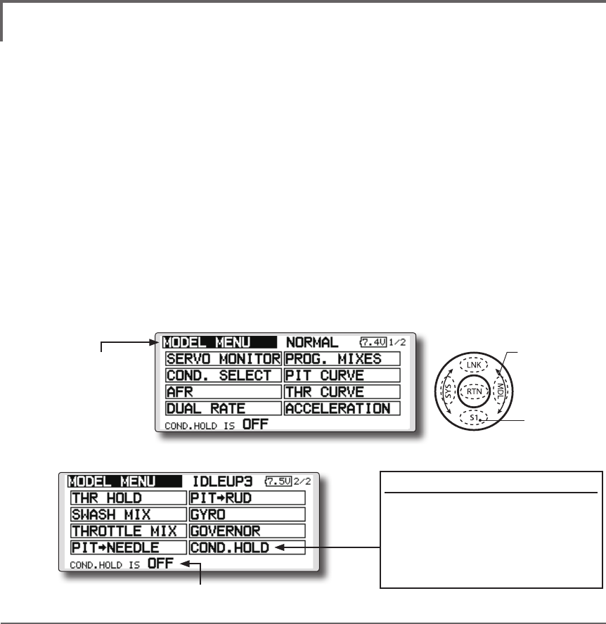
150 <Functions of Model Menu (Helicopter Functions) >
●Selectthefunction
nameandreturntothe
precedingscreenby
touchingtheRTNbutton
orpushingtheHome/Exit
button.
<SensorTouch™>
MODEL MENU (HELICOPTER)
This section contains information on the
commands that apply to helicopters only. For
instructions on airplanes and sailplanes, refer to the
sections pertaining to those aircraft.
Use the Model Type function in the Linkage
Menu to select the swash type matched to the
fuselage beforehand.
Also, add flight conditions at the Condition
Select screen if necessary before setting the model
data at each function. (Up to 8 conditions can be
used)
The AFR function, dual rate function and other
functions common to all model types, are described
in a separate section.
Model Menu functions (helicopter) list
PIT CURVE: Adjusts response in different ight conditions
THR CURVE: Throttle curve and hovering trim adjustment
ACCELERATION: Allows a brief "overload" in response to sudden throttle and pitch commands
THR HOLD: Moves the throttle to idle during autorotation
SWASH MIX: Compensates for each control response
THROTTLE MIX: Compensates for power loss when cyclic applied
PIT to NEEDLE: Adjusts response curve in different ight conditions
PIT to RUD: Handles torque changes from pitch angle inputs
GYRO: Used to switch gyro sensitivity
GOVERNOR: Used to switch RPM of the helicopter’s head
To activate/deactivate Condition Hold:
1.Movethecursorto[COND.HOLD].
2.Setthethrottlesticklowerthan
the1/3pointandtouchthe RTN
buttontoactivate/deactivate the
conditionholdfunction.
*Refer to for condition hold function details.
*Condition hold operation is displayed.
●Selectthe[MODEL]atthehomescreen
andcallthemodelmenushownbelowby
touchingtheRTNbutton.
●Usethetouchsensortoselectthefunction
youwanttosetandcallthesetupscreenby
touchingtheRTNbutton.
Scrolling
●Movingcursor
●Tonextpage
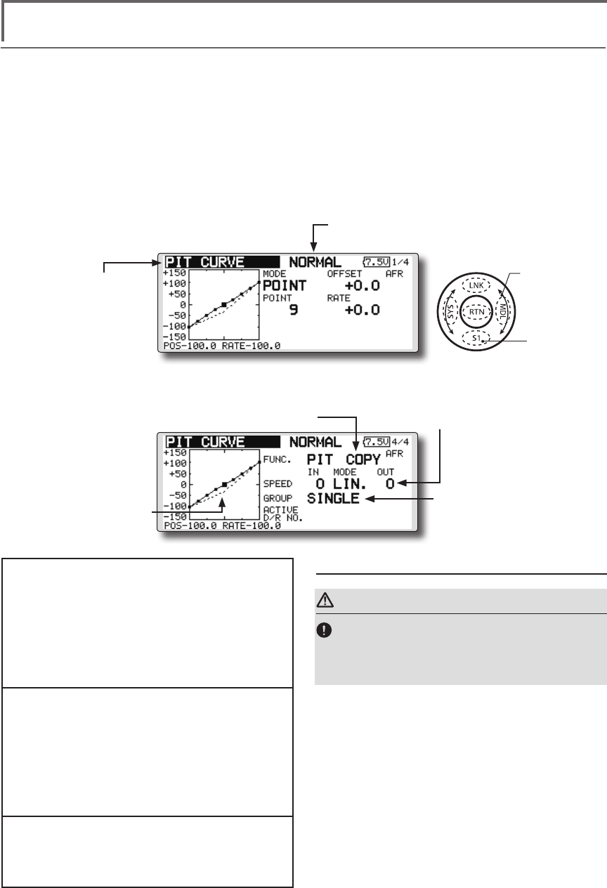
151
<Functions of Model Menu (Helicopter Functions) >
●Selectthefunction
nameandreturntothe
precedingscreenby
touchingtheRTNbutton
orpushingtheHome/Exit
button.
<SensorTouch™>
PIT CURVE/PIT TRIM
PIT Curve
This function adjusts the pitch operation curve
for each ight condition for the optimal ight state
relative to movement of the throttle stick.
*Up to 17 points can be set for the point curve types.
However, when using the 3 points or 5 points specied to
create a curve, a simple curve can be created by reducing
the number of input points to 3 or 5, and then entering the
specied value at the corresponding points that you created
a curve.
●Pointcurvetypeis9points
(initial),butforsimpleuse,
4~5pointsaresufcient.
Normal curve adjustment
●Fornormalcurve,usuallyuse[POINT]type
andcreateabasicpitchcurvecentered
abouthovering.Usethisfunctiontogether
withtheTHRcurve(normal)functionand
adjustthecurvesothatup/downcontrolis
bestataconstantenginespeed.
Idle up curve adjustment
●Forthehighsidepitchcurve,setthe
maximumpitchwhichdoesoverloadthe
engine.Forthelowsidepitchcurve,create
curvesmatchedtoloop,roll,3D,and
otherpurposesandusetheidleupcurves
accordingtotheperformance.
Throttle hold curve adjustment
●Thethrottleholdcurveisusedwhen
executingautorotationdives.
Operation precautions
WARNING
When actually starting the engine and flying,
always set the idle up condition switch to OFF
and start the engine in the idling state.
(Currently selected condition name)
●Select[PITCURVE]atthemodelmenu
andcallthesetupscreenshown
belowbytouchingtheRTNbutton.
●Group/singlemode
switching
(For more information, refer to
the description at the back of this
manual.)
●Mixingcurvesetting
*For a description of the curve setting method, see the
description at the back of this manual.
●Pitchservospeedsetting
(For a description of the setting
method, see the description at the
back of this manual.)
●Pitchtrimcopy
●Pitchtrimoperating
position(dotted
line)
Scrolling
●Movingcursor
●Selectingmode
●Adjustingvalue
●Tonextpage
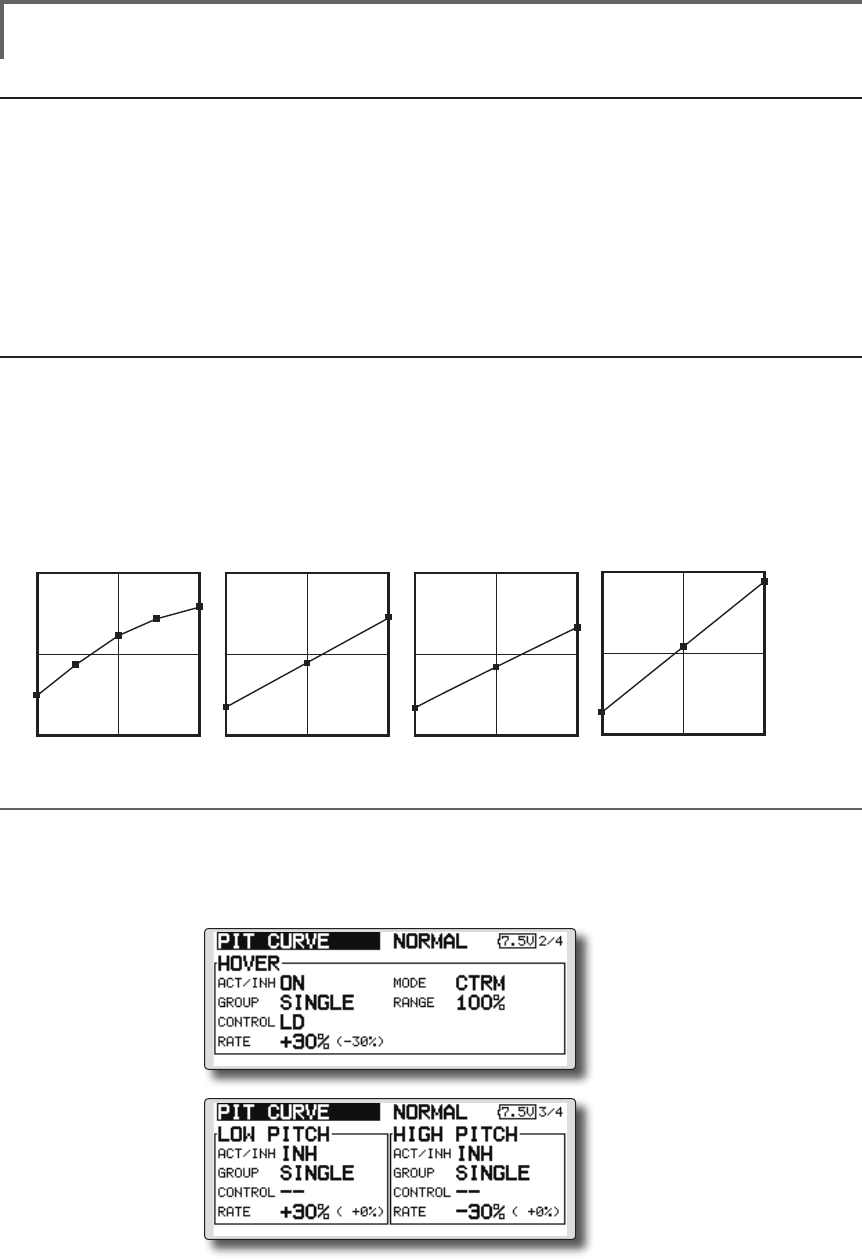
152 <Functions of Model Menu (Helicopter Functions) >
Normal Curve Idle-up 1 Curve Idle-up 2 Curve Hold Curve
●Pitch Curve (Example)
●Group/Singleitem:Whenyoualsowantto
inputthesamesettingcontentsatother
conditions,performsettinginthegroup
mode.Inthiscase,thesamecontentsare
inputtotheotherconditionssetinthegroup
mode.Whenyouwanttoseteachcondition
independently,selectthesinglemode
(initialsetting).Otherconditionscanbeset
independently.
Setting method
●Pittrimcopy(Hover/high/low)
Thepitchtrimoperatingpositioncanbe
copiedtothepitchcurve.
Movethecursortothe[COPY]itemand
touchtheRTNbutton.
Aftercopying,returnthepitchtrimtothe
centertocallthelastoperatingposition.
The screens shown below are curves created
by entering the pitch rate at low, center, and high
side (3 points or 5 points) at each condition. When
actually creating a curve, input the rate specied at
the fuselage (or the reference value).
*For a description of the curve setting method, see the
description at the back of this manual.
Curve setting examples
(Continued on next page)
Pitch Trim (Hovering pitch, high pitch, low pitch)
The hovering pitch, low pitch, and high pitch trim setup screen can be called from the PIT curve setup
screen.
●Hoveringpitch
trimsetting
●Low/highpitch
trimsetting

153
<Functions of Model Menu (Helicopter Functions) >
Hovering pitch trim
The Hovering Pitch trim function trims the pitch
near the hovering point. Normally, it is used with
the hovering condition. The hovering pitch can be
ne tuned for changes in rotor speed accompanying
changes in temperature, humidity, and other ight
conditions. Adjust the hovering pitch so that
rotor speed is constant. This function can be used
together with the hovering Throttle Trim function
for more delicate operation.
Setting method
●Whenusingonlythehovering(normal)
condition,switchthegroupmodetothe
singlemode(initialsetting)beforesetting.
●SetthefunctiontoACT[ON].
●Selecttheadjustmentknob.
Selectionexample:LD
●Thetrimoperationmode(Mode:CTRM/
NORM)canbeselected.
CTRMmode:Maximumamountofchange
nearcenterbycentertrimoperation
(recommended)
NORMmode:Normaltrim(parallel
movementtrim)operation.Theadvantage
ofusingthismodeisthatthehoveringpitch
canbeadjustedwithoutchangingthe
curve.
●Trimadjustmentrange(Range)setting
Whenthisvalueismadesmall,trimcanonly
beusednearthecenter.
●Thetrimratecanbeadjustedandthe
operationdirectioncanbechanged.
High Pitch/Low Pitch Trim
High Pitch/Low Pitch Trim is the pitch servo
high side and low side trim function.
Setting method
●Whensettingtheadjustmentknobscommon
toalltheconditions,settheminthegroup
mode.
●SetthefunctiontoACT(ON).
●Selecttheadjustmentknobs.
Selectionexample:LS(highside),RS(low
side)
●Thetrimratecanbeadjustedandthe
operationdirectioncanbechanged.
●Trimactsashighsideorlowsidetrimwiththe
centerasthestandard.
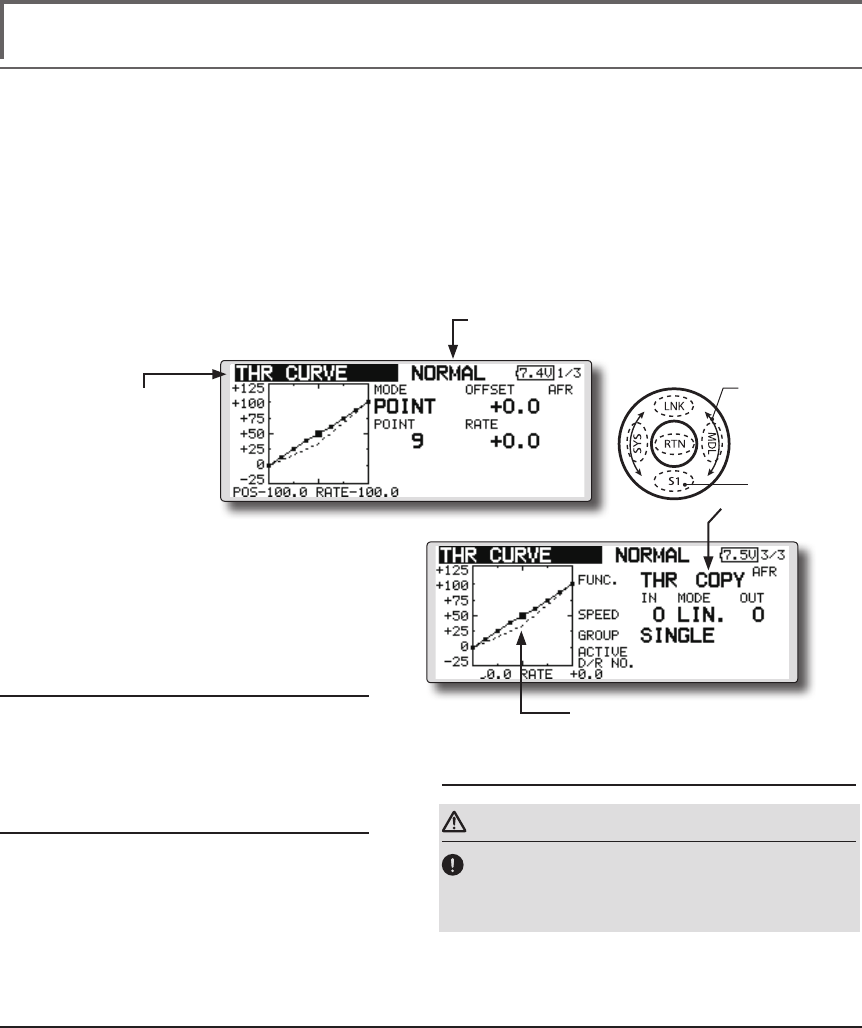
154 <Functions of Model Menu (Helicopter Functions) >
●Selectthefunction
nameandreturntothe
precedingscreenby
touchingtheRTNbutton
orpushingtheHome/Exit
button.
<SensorTouch™>
THR CURVE/THROTTLE HOVER TRIM
THR Curve
This function adjusts the throttle operation curve
for each condition for optimum engine speed to
throttle stick movement.
Up to 17 curve points can be set for the point
curve type, however, when the 5 points and other
point data is used, a simple curve can be easily
created by reducing the number of input points of
the curve to 5 and entering the specified value at
the corresponding points.
Normal curve adjustment
●Normalcurvecreatesabasiccurve
centeredaroundhovering.Useitalong
withthenormalpitchcurveandadjustso
thatup/downcontrolataconstantengine
speediseasiest.
Idle up curve adjustment
●Setaidleupcurvethatmaintainsaconstant
speedatalltimes,evenduringoperation
whichreducesthepitchperformedinight.
Createacurvematchedtoloop,roll,3D,
orotherpurposesandtheidleupcurve
accordingtotheperformance.
Operation precautions
WARNING
When actually starting the engine and flying,
always set the idle up condition switch to OFF
and start the engine in the idling mode.
Setting method
●Group/singleitem:Whenyouwantto
simultaneouslyenterthesamesettingsto
otherfunctions,makethesettingsinthe
groupmode.Inthiscase,thesamesetting
contentsareenteredtotheallconditions.
Whenyouwanttoseteachcondition
independently,makethesettingsafter
selectingthesinglemode(Initialsetting).
●Throttlehovertrimcopy
Thethrottlehovertrimoperatingpositioncan
becopiedtothethrottlecurve.
Movethecursortothe[COPY]itemand
touchtheRTNbutton.
Aftercopying,returnthepitchtrimtothe
centertocallthelastoperatingposition.
(Currently selected condition name)
●Select[THRCURVE]atthemodelmenu
andcallthesetupscreenshown
belowbytouchingtheRTNbutton.
●Mixingcurvesetting
*For a description of the curve setting
method, see the description at the back
of this manual.
●Throttlehover
trimcopy
●Throttlehovertrimoperating
position(dottedline)
Scrolling
●Movingcursor
●Selectingmode
●Adjustingvalue
●Tonextpage
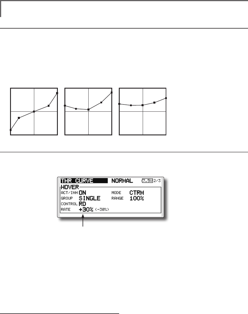
155
<Functions of Model Menu (Helicopter Functions) >
Normal Curve Idle-up 1 Curve Idle-up 2 Curve
●Throttle Curve (Example)
The curves shown below are created by using
the point curve type and inputting the data of the
5 points 0% (low side), 25%, 50% (center), 75%,
100% (high) side at each condition. They are
created by reducing the number points of the line
to 5. When actually creating a curve, enter the data
specied per the aircraft (or the reference value).
*For a description of the curve creation method, see the
description at the back of this manual.
Curve setting examples
Throttle Hover trim
The Throttle Hover trim setup screen can be called from the THR Curve setup screen.
The Throttle Hover function trims the throttle
near the hovering point. Normally, use it with
hovering conditions. Changes in rotor speed
accompanying changes in the temperature,
humidity, and other flight conditions can be
trimmed. Adjust the throttle so that rotor rotation is
most stable. More delicate trimming is also possible
by using this function along with the Hover Pitch
function.
Setting method
●Whenusingthehovering(normal)condition
only,switchthegroupmodetothesingle
mode(initialsetting)andmakethesettings.
●SetthefunctiontoACT([ON]).
●Selecttheadjustmentknob.
Selectionexample:RD
●Thetrimoperationmode(Mode:CTRM/
NORM)canbeselected.
CTRMmode:Maximumrateofchange
nearcenterbycentertrimoperation
(recommended)
NORMmode:Normaltrim(horizontal
movementtrim)operation.
●Trimadjustmentrange(Range)setting
Whenthevalueismadesmall,trimactsonly
nearthecenter.
●Thetrimratecanbeadjustedandthe
operationdirectioncanbeset.
●Setsthedialused.
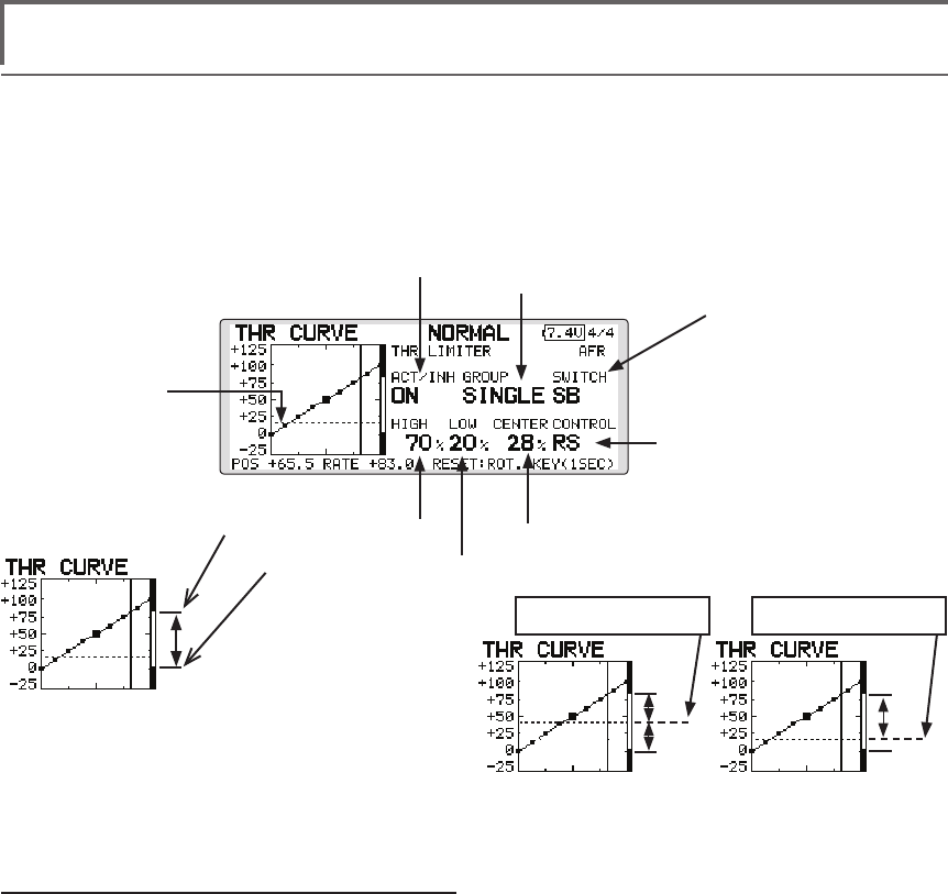
156 <Functions of Model Menu (Helicopter Functions) >
Setting method
●Activatethefunction
1.Select"ACT/INH"andtouchtheRTNbutton.
2.Scrollingthetouchsensorandswitchthe
displayto[INH]or[ACT].
3.TouchtheRTNbutton.
●Group/singlemodeselection.
1.Select"GROUP"andtouchtheRTNbutton.
2.Scrollingthetouchsensorandswitchthe
displayto[GROUP]or[SINGLE].
3.TouchtheRTNbutton.
●ON/OFFswitchsetting
1.Select"SWITCH"andtouchtheRTNbutton.
2.Ahardwareselectionscreenisdisplayed.
SelectthehardwareandtouchtheRTN
button.
●Hightsideoperationrangesetting
1.Select"HIGH"andtouchtheRTNbutton.
2.Scrollingthetouchsensorandadjustthehigh
sideoperationrange.
3.TouchtheRTNbutton.
●Lowsideoperationrangesetting
1.Select"LOW"andtouchtheRTNbutton.
2.Scrollingthetouchsensorandadjustthelow
sideoperationrange.
3.TouchtheRTNbutton.
●Theneutralpositionof"CONTROL"setting
1.Select"CENTER"andtouchtheRTNbutton.
2.Scrollingthetouchsensorandadjustthe
neutralposition.
3.TouchtheRTNbutton.
●Limiteractivationpositionadjustmentcontrol
setting
1.Select"CONTROL"andtouchtheRTNbutton.
2.Ahardwareselectionscreenisdisplayed.
SelectthehardwareandtouchtheRTN
button.
Throttle Limiter
*When the limiter operation range adjustment control is
NULL, the throttle limiter function is not activated.
This function limits throttle operation to within a
certain range. Control which adjusts the operating
range during ight can be set. (Effective only when
the model type is helicopter.)
● Open the THR CURVE setup
screen. Push S1 button to
advance to next page and
display page4.
● Throttle limiter
activation position
● Condition group/single
● Throttle limiter function
ACT/INH
● Mixing ON/OFF switch
● Limiter activation position
adjustment control
● The limit value at the operation hardware neutral
position can be adjusted using the throttle limiter.
● High side operation range
● Low side operation range
● When CENTER is INH.
The motion with the
equal upper and lower
sides is carried out.
● When CENTER is 28%.
The amount of operations
above CONTROL
increases.
The high side of a
throttle can restrict
to this range by
CONTROL.
The neutral position of
CONTROL
The neutral position of
CONTROL
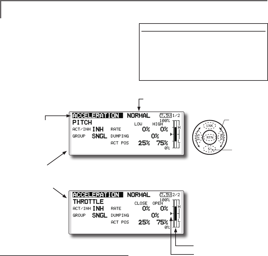
157
<Functions of Model Menu (Helicopter Functions) >
●Selectthefunction
nameandreturntothe
precedingscreenby
touchingtheRTNbutton
orpushingtheHome/Exit
button.
<SensorTouch™>
ACCELERATION
This function is used to adjust the pitch and
the throttle rise characteristic at acceleration/
deceleration operation. An acceleration function
which temporarily increases the pitch and throttle
operations at throttle stick acceleration/deceleration
operation can be set.
Example of acceleration function use
●Whenusedatpitch,theacceleration
functioniseffectivewhenyouwantto
quickentheresponseofthefuselageat3D
ightip,etc.
Whenused,highpitchtemporarilyexceeds
maximumpitch,butimmediatelyreturnsto
maximumpitch.
●Pitchsetting
●Throttlesetting
Setting method
●Accelerationcanbesetatbothsetting
atacceleration(high)andsettingat
deceleration(low).
(Theoperationpointisdisplayedona
graph.)
●Accelerationratesetting(Rate)
●Thereturntimeafteroperation(Dumping)
canbeset.
●Theoperationpointatacceleration
anddecelerationcanbeset.Whenan
operationpointisexceeded,accelerationis
performed.
Note:Whenusingtheaccelerationfuntion,
sincethepitchstrokeislarge,makeyour
settingssothereisnobindingofyourlinkage.
(Currently selected condition name)
●Select[ACCELERATION]atthemodel
menuandcallthesetupscreenshown
belowbytouchingtheRTNbutton.
●Actposition
●Currentposition
Scrolling
●Movingcursor
●Selectingmode
●Adjustingvalue
●Tonextpage

158 <Functions of Model Menu (Helicopter Functions) >
●Selectthefunction
nameandreturntothe
precedingscreenby
touchingtheRTNbutton
orpushingtheHome/Exit
button.
<SensorTouch™>
THR HOLD
This function sets the throttle cut position for
auto rotation. The throttle position can also be set
to an idling position. Setting of these 2 positions
can be selected by switch. This allows use for
switching during training.
Example of use
●Sincethrottleholdhas2modes(Cut)and
(Idle),usingitintheIdlingmodeduring
trainingandintheCutmodewhen
stoppingtheengineatmeets,etc.is
convenient.
Note:WhenthrottleholdissettoONinthenormal
condition,throttleholdactsandthethrottleservo
isdeactivated.AlwayssetthrottleholdtoONinthe
holdcondition.
●Settotheenginestopposition.
●Settotheidlingposition.
Setting method
●Operationmodeselection
Manualmode(MANUAL):Thethrottlehold
functionisoperatedbyswitchoperation
only.
Automode(AUTO):Thethrottleholdfunction
operationislinkedtothethrottlestick
position.
Autopositionsetting:Whentheautomodeis
selected,thethrottleposition(autoposition)
canbeselected.Movethethrottlestickto
thepositionyouwanttosetandtouchthe
RTNbutton.(Autopositionisdisplayed.)
●Holdpositionadjustment
ThrottleHold(Cut)setsthethrottlecut
position.Adjustitsothatthecarburetorisfull
close.
ThrottleHold(Idle):Makethisadjustmentto
maintainidlingfortraining.Adjustments can
bemadebasedonthethrottlecurveidle
position.
●Thethrottleservooperating speedcanbe
adjusted.(Speed)
●Throttlecutortrainingfunctioncanbe
switchedbyholdfunctionselectorswitch.
Operation precautions
WARNING
When starting the engine, conrm that the idle up
condition and throttle hold condition are OFF.
(Currently selected condition name)
●Select[THRHOLD]atthemodelmenu
andcallthesetupscreenshown
belowbytouchingtheRTNbutton.
●Holdposition
●Currentposition
Scrolling
●Movingcursor
●Selectingmode
●Adjustingvalue
●Tonextpage
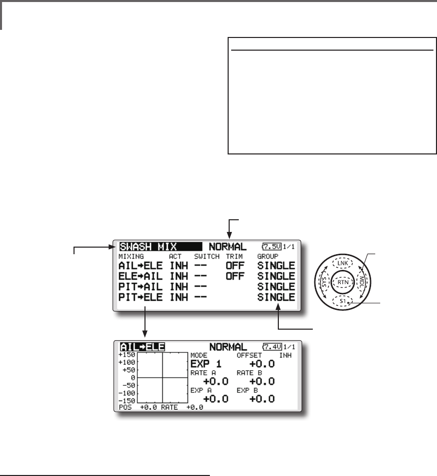
159
<Functions of Model Menu (Helicopter Functions) >
●Selectthefunction
nameandreturntothe
precedingscreenby
touchingtheRTNbutton
orpushingtheHome/Exit
button.
<SensorTouch™>
SWASH MIX
The swash mix function is used to correct the
swash plate in the aileron (roll) direction and
elevator (cyclic pitch) corresponding to each
operation of each condition.
Adjustment by independent curve for aileron,
elevator, and pitch operations is possible. The
operation can be smoothly adjusted by calling up
the “Curve setup” screen by touching the EDIT
button with moving the cursor to the mixing item
that corresponds to the mixing and direction which
needs correction.
Example of use
●Asanexample,useswashmixingtocorrect
undesirabletendenciesintherolldirection
●ForaconditionwhichusesAILtoELE,setthis
functiontoON.Whenraisingthenoseata
rightroll,whentheRateBsideisinputand
therightaileronisoperated,theelevator
movestothedownside.Tunebyadjusting
theRate.Forrightroll,adjusttotherateA
side.
Setting method
●Whenusingthisfunction,movethecursor
tothe[ACT]itemandtouchtheRTNbutton
toswitchtothedatainputmode.Turnthe
touchsensortotheleft andtouchtheRTN
button.(ONisdisplayed.)
●Whenyouwanttosetthesamecontentsat
otherconditions,selectthegroupmode.
Whenyouwanttosettheselectedcondition
only,selectthesinglemode(initialsetting).
●Thecorrectionratecanbesetbycurve.
● Aswitchcanbeset.
When[[--]]isset,theswashmixingfunctionis
operatedbymerelyselectingthecondition.
Whensettingan[ON]/[OFF]switch,move
thecursortothe[--]itemandtouchtheRTN
buttontocalltheselectionscreenandset
theswitchanditsONposition.
(Currently selected condition name)
●Select[SWASHMIX]atthemodel
menuandcallthesetupscreenshown
belowbytouchingtheRTNbutton.
●Group/singlemode
switching
(For more information, refer to
the description at the back of this
manual.)
●Mixingcurvesetting
*For a description of the curve setting method, see the
description at the back of this manual.
Scrolling
●Movingcursor
●Selectingmode
●Tonextpage
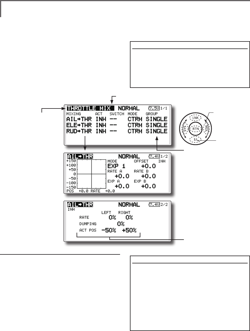
160 <Functions of Model Menu (Helicopter Functions) >
●Selectthefunction
nameandreturntothe
precedingscreenby
touchingtheRTNbutton
orpushingtheHome/Exit
button.
<SensorTouch™>
THROTTLE MIX
This function corrects slowing of engine speed
caused by swash plate operation during aileron
or elevator operation. The method of applying
clockwise or counterclockwise torque when
pirouetting can also be corrected.
An acceleration function which temporarily
increases the throttle side correction rate relative to
rapid stick operation can also be set.
Setting example
●AILtoTHRappliesaloadtotheengineand
correctsslowingoftheenginespeedwhen
theaileronstickwasoperated.Engine
racingcanbeadjustedindependentlyat
therightaileronandleftaileronbyRatesA
andB.
Setting method
●Whenusingthisfunction,movethecursor
tothe[ACT]itemandtouchtheRTNbutton
toswitchtothedatainputmode.Turnthe
touchsensortotheleft andtouchtheRTN
button.(ONisdisplayed.)
●Whenyouwanttosetthesamecontentsat
otherconditions,selectthegroupmode.
Whenyouwanttosettheselectedcondition
only,selectthesinglemode(initialsetting).
●Thecorrectionratecanbesetbycurve.
●Aswitchcanbeset.
When[[--]]isset,theswashmixingfunctionis
operatedbymerelyselectingthecondition.
Whensettingan[ON]/[OFF]switch,move
thecursortothe[--]itemandtouchtheRTN
buttontocalltheselectionscreenandset
theswitchanditsONposition.
When correction is necessary, move the cursor
to the mixing item corresponding to the mixing
that needs correction and touch the RTN button to
call the curve setup screen, and then correct the
slowing.
<Acceleration function setting>
●Accelerationcanbesetforbothsettings
(Left)and(Right)
●Accelerationratesetting(Rate)
●Thereturntime(Dumping)afteroperation
canbeset.
●Theoperationpointwhenthecorrection
rateisincreasedanddecreasedcanbe
setindependently.Whenanoperation
pointisexceeded,accelerationoperation
isperformed.
(Currently selected condition name)
●Select[THROTTLEMIX]atthemodel
menuandcallthesetupscreenshown
belowbytouchingtheRTNbutton.
●Group/singlemode
switching
(For more information, refer to
the description at the back of
this manual.)
●Mixingcurvesetting
*For a description of the
curve setting method,
see the description at the
back of this manual.
●Accelerationsettings
Scrolling
●Movingcursor
●Selectingmode
●Tonextpage
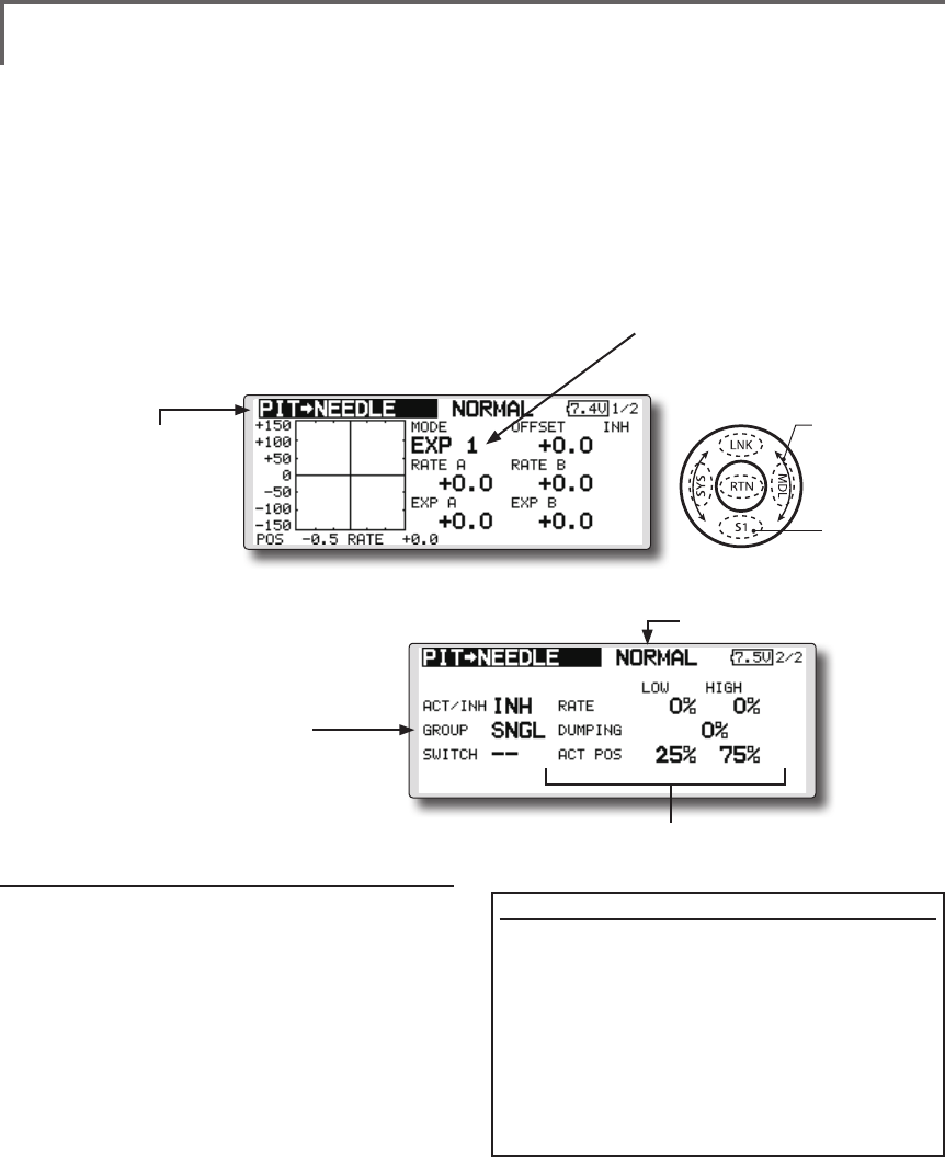
161
<Functions of Model Menu (Helicopter Functions) >
●Selectthefunction
nameandreturntothe
precedingscreenby
touchingtheRTNbutton
orpushingtheHome/Exit
button.
<SensorTouch™>
PIT to NEEDLE mixing
This mixing is used when the engine is equipped
with needle control or other fuel-air mixture
adjustment. A needle curve can be set.
An acceleration function which temporarily
increases needle operation at throttle stick
Setting method
●Whenusingthisfunction,movethecursor
tothe[ACT]itemandtouchtheRTNbutton
toswitchtothedatainputmode.Turnthe
touchsensortotheleft andtouchtheRTN
button.(ONisdisplayed.)
●Whenyouwanttosetthesamecontentsat
otherconditions,selectthegroupmode.
Whenyouwanttosettheselectedcondition
only,selectthesinglemode(initialsetting).
● Aneedlecurvecanbeset.
● Aswitchcanbeset.
When[[--]]isset,themixingfunctionis
operatedbymerelyselectingthecondition.
Whensettingan[ON]/[OFF]switch,move
thecursortothe[--]itemandtouchtheRTN
buttontoswitchtothedatainputmode.
TouchtheRTNbuttontocalltheselection
screenandsettheswitchanditsONposition.
< Acceleration function setting>
●Accelerationcanbesetatboth setting
atacceleration(high)andsettingat
deceleration(low).
●Theaccelerationrate(rate)andthereturn
timeafteroperation(dumping)canbeset.
●Anoperationpoint(actpos)atacceleration
anddecelerationcanbeset.When
anoperationpointwasexceeded,
accelerationoperationisperformed.
●Normally,use[POINT]type.
●Select[PITtoNEEDLE]atthemodelmenuandcall
thesetupscreenshownbelowbytouchingthe
RTNbutton.
(Currently selected condition name)
acceleration/deceleration operation can be set.
The rise characteristic of the needle servo at
acceleration and deceleration operation can be
adjusted.
●Group/singlemodeswitching
(For more information, refer to the
description at the back of this manual.)
●Mixingcurvesetting
*For a description of the curve setting method, see
the description at the back of this manual.
●Accelerationsettings
Scrolling
●Movingcursor
●Selectingmode
●Adjustingvalue
●Tonextpage
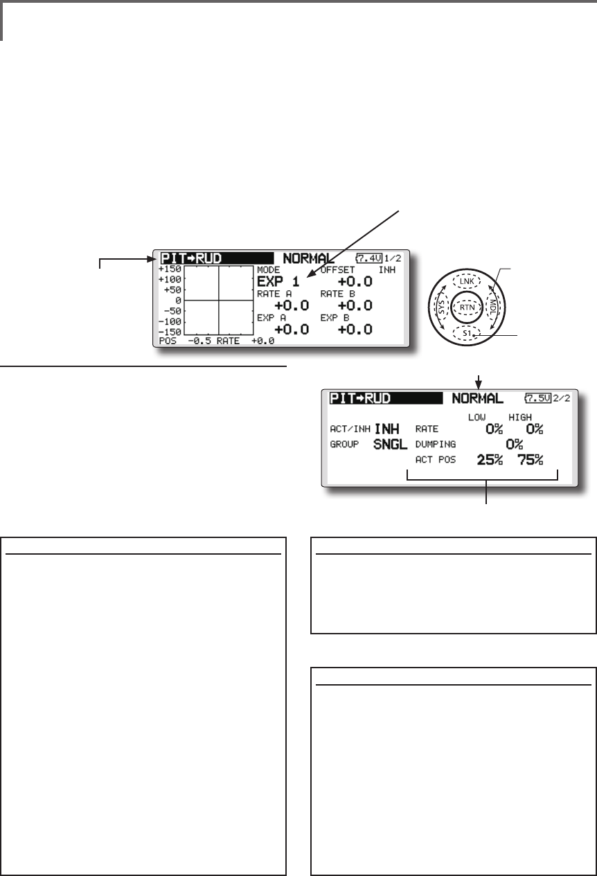
162 <Functions of Model Menu (Helicopter Functions) >
●Selectthefunction
nameandreturntothe
precedingscreenby
touchingtheRTNbutton
orpushingtheHome/Exit
button.
<SensorTouch™>
PIT to RUD mixing (Revolution mixing)
Use this mix when you want to suppress the
reaction torque generated by main rotor pitch and
speed changes during pitch operation. Adjust so
that the nose does not move in the rudder direction.
An acceleration function which temporarily
increases the correction rate at throttle stick
acceleration/deceleration operation can be set. The
mixing rate at acceleration/deceleration can be set.
Setting method
●Whenusingthisfunction,movethecursor
tothe[ACT]itemandtouchtheRTNbutton
toswitchtothedatainputmode.Turnthe
touchsensortotheleft andtouchtheRTN
button.(ONisdisplayed.)
●Whenyouwanttosetthesamecontentsatother
conditions,selectthegroupmode.
Whenyouwanttosettheselectedconditiononly,
selectthesinglemode(initialsetting).
●Amixingcurveisset.
<Normal condition mixing curve>
Themixingcurveratestartsfromasmall
value.
Forarotorwithaclockwiseoperation
direction(polarity),whenpitchwas
operatedattheplusside,setsothatmixing
isintheclockwisedirection.First,trimat
hoveringandthenadjusttheneutral
position.
1.Adjustmentbetweenslowandhovering
Repeatedlyhoverfromtakeoffandland
fromhoveringataconstantratematched
toyourownrhythm,andadjustthepitchso
thenosedoesnotdeectwhenthethrottle
israisedandlowered.
2.Throttlehighside(climbinganddivingfrom
hovering)
Repeatclimbinganddivingfromhovering
ataconstantratematchedtoyourown
rhythmandadjustthepitchsothatthenose
doesnotdeflectwhenthethrottleisraised
andlowered.
However, when a GY Series or other heading
hold gyro is used, since correction is performed
by the gyro, this mix is not used. If this function
is used when the gyro operation mode is the
AVCS mode, the neutral position will change.
<Idle up condition mixing curve>
Setthemixingratesothat therudderdirection
athigh-speedightisstraightahead.Adjustfor
eachconditionused.
<Acceleration function setting>
●Accelerationoperationcanbeperformed
forbothsettingatacceleration(high)and
settingatdeceleration(low).
●Accelerationratesetting(rate)
●Thereturntimeafteroperation(dumping)
canbeset.
●Anoperationpoint(actpos)at
accelerationanddecelerationcanbeset
independently.Whenanoperationpoint
wasexceeded,accelerationoperationis
performed.
●Normally,use[POINT]type.
●Select[PITtoRUD]atthemodelmenuandcallthe
setupscreenshownbelowbytouchingtheRTN
button.
(Currently selected condition name)
●Accelerationsettings
Scrolling
●Movingcursor
●Selectingmode
●Adjustingvalue
●Tonextpage
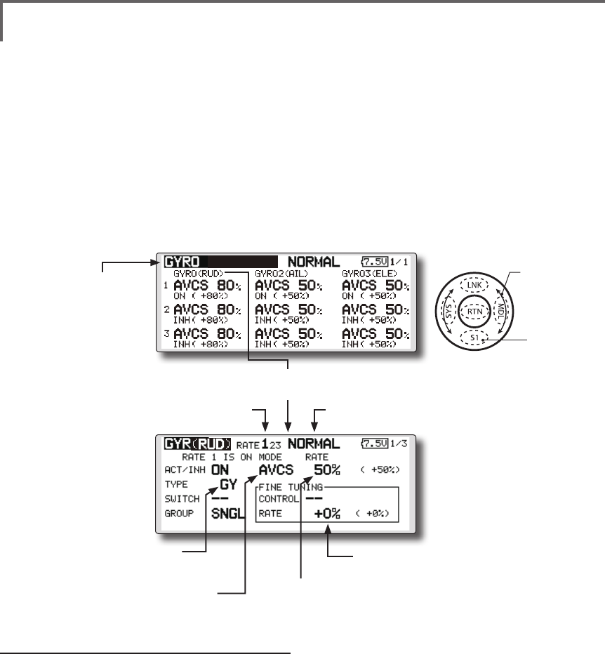
163
<Functions of Model Menu (Helicopter Functions) >
●Selectthefunction
nameandreturntothe
precedingscreenby
touchingtheRTNbutton
orpushingtheHome/Exit
button.
<SensorTouch™>
GYRO mixing
This function used to adjust gyro sensitivity.
The sensitivity and operation mode (Normal mode/
AVCS mode) can be set for each condition.
The gyro sensitivity can be switched with each
condition or the switch. (5 sensitivities)
*Compatible with 3 axis gyro(CGY750).
Setting method
● Whenusingthisfunction,movethecursor
tothe[ACT]itemandtouchtheRTNbutton
toswitchtothedatainputmode.Turnthe
touchsensortotheleft andtouchtheRTN
button.(ONisdisplayed.)
● Whenyouwanttosetthesamecontentsat
otherconditions,selectthegroupmode.
Whenyouwanttosettheselectedcondition
only,selectthesinglemode(initialsetting).
● Threeratescan beswitched foreach
condition.(Rate1/Rate2/Rate3)
● AnetuningVRcanbeset.
●Select[GYRO]atthemodelmenuandcallthe
setupscreenshownbelowbytouchingtheRTN
button.
(Currently selected condition name)(Rate No. display)
●FinetuningVRsettings
●Gyrosensitivityadjustment
●Modeselection:
[AVCS]/[NORM]
●Gyrotypeselection:
[GY]/[NORM]
Note:Whenusingthe[Gyro2]/[Gyro3]function,
assign[Gyro2]/[Gyro3]toanychannelon
thefunctionscreen.
Alwayssetto[--]both(control)and(trim)for
the[Gyro]functionattheFunctionmenuin
theLinkagemenu.
●WhentheGYROfunctionbuttonisselected,each
GYROdetailedsettingscreenappears.
Scrolling
●Movingcursor
●Selectingmode
●Adjustingvalue
●Tonextpage
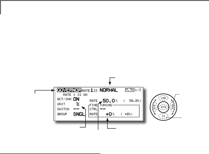
164 <Functions of Model Menu (Helicopter Functions) >
●Selectthefunction
nameandreturntothe
precedingscreenby
touchingtheRTNbutton
orpushingtheHome/Exit
button.
<SensorTouch™>
GOVERNOR mixing
When using a Futaba governor, this function is
used to switch the RPM of the helicopters head. Up
to 3 rates can be set for each condition.
*The governor is used by connecting the governor speed
setting channel to CH7 (initial setting).
*When using an independent governor [ON]/[OFF] switch,
connect the AUX([ON]/[OFF]) connector of the governor to
CH8 (initial setting) and set the switch to CH8 (Governor2)
at the Function menu of the Linkage Menu.
*When using the Fuel Mixture function, the mixture servo
is controlled from the governor. When transmitting the
mixture curve data from the transmitter to the governor, the
governor AUX (m.trm) connector must be connected to CH8
(initial setting) and governor side setting performed. See the
governor instruction manual.
Note:Alwaysset(Control)and(Trim)to[--]for
[Governor]and[Governor2]oftheFunctionmenu
oftheLinkagemenu.
●Select[GOVERNOR]atthemodelmenu
andcallthesetupscreenshownbelow
bytouchingtheRTNbutton.
(Currently selected condition name)
●FinetuningVRsettings
●RPMadjustment
●Unitdisplayselection:
[%]/[rpm]
Setting method
●Activate the mixing
Whenusingthisfunction,movethecursorto
the[INH]itemandtouchtheRTNbuttonto
switchtothedatainputmode.
SelecttheACTmodebyscrollingthetouch
sensor.
*The display blinks.
TouchtheRTNbuttontoactivatethemixing
andreturntothecursormode.(ONis
displayed.)
WhentheGovernorischangedfromthe
defaultinhibited(INH)statetotheactive
(ACT)state,theendpointmenuwillbe
displayedanditispossibletoutilizethe
endpointsforthisgivencondition.
*When the function is set ON/OFF at the governor setup
screen, the governor rpm setting channel end point servo
travel and limit point are now initialized.
*When changed from INH to ACT (ON), the servo travel is
initialized to 100 and the limit point is initialized to 155.
*When operation is changed to INH at all conditions, the
servo travel is initialized to 100 and the limit point is
initialized to 135.
●RPM adjustment
Movethecursortotherateitemandtouch
theRTNbuttontoswitchtothedatainput
mode.
Adjusttherpmbyscrollingthetouchsensor.
Initialvalue:50%(1500rpm)
Adjustmentrange:OFF,0~110%(OFF,
700~3500rpm)
*When the RTN button is touched for one second, the
sensitivity is reset to the initial value.)
TouchtheRTNbuttontoreturntothecursor
mode.
●Unit diplay selection
MovethecursortotheUNITitemandtouch
theRTNbuttontoswitchtothedatainput
mode.Selecttheunitbyscrollingthetouch
sensor.
TouchtheRTNbuttontochangethe
operationmodeandreturntothecursor
mode.
Scrolling
●Movingcursor
●Selectingmode
●Adjustingvalue
●Tonextpage
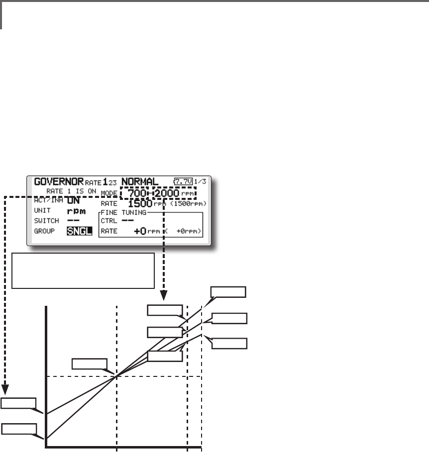
165
<Functions of Model Menu (Helicopter Functions) >
●Diplay mode selection
*When [rpm] mode is selected above setting, the display
mode can be selected.
* There is no change in the transmitter output even when the
"MODE" is changed. Calibration should be performed via
the governor.
* In order to use the Governor function of the T18SZ, it is
necessary to change the settings on the governor for the low
side 700 rpm mode.
WhentheMODEoftheGovernorscreen's
modelmenuischanged,thechangeisalso
indicatedon-screen.
The chart below indicates the
mode percentage and the
corresponding RPM.
●Fine tuning VR settings
Movethecursortothe[--]itemandtouch
theRTNbuttontoaccesstheselection
screen.Selectthecontrol.
*For a description of the switch selection method, see the
description at the back of this manual.
Movethecursortotherateitemandtouch
theRTNbuttontoswitchtothedatainput
mode.
Adjustthetrimratebyscrollingthetouch
sensor.
main rotor R.P.M.
3900rpm
2700rpm
2100rpm
0% 100% 110%
main rotor R.P.M. setting channel travel
50% : neutral
2500rpm
2000rpm
1500rpm
1000rpm
700rpm
3500rpm
Initialvalue:0%(0rpm)
Adjustmentrange:-20~+20%(-800~+800rpm)
*When the RTN button is touched for one second, the
sensitivity is reset to the initial value.)
TouchtheRTNbuttontoreturntothecursor
mode.
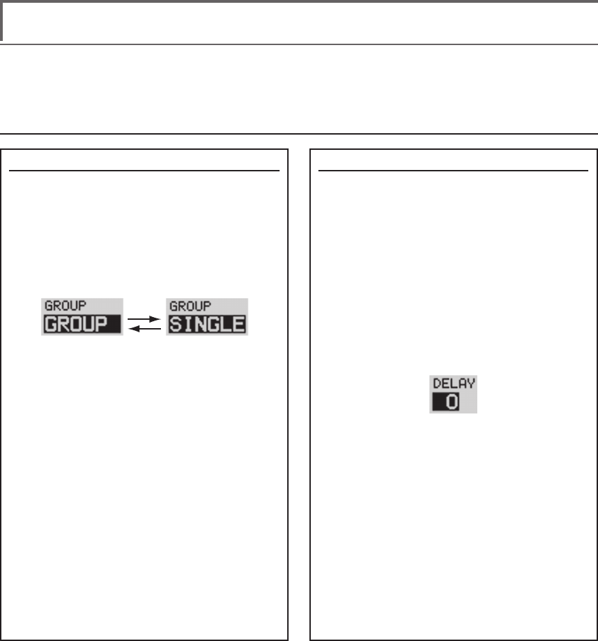
166 <Data>
Common operations used in function setup screen
This section describes the functions often used at the function setup screen. Refer to it when setting each
function.
Group/single mode switching (GROUP/SINGLE)
When setting multiple flight conditions,
linking the setting contents with all conditions
(group mode) or setting independently (single
mode) can be selected. The mode can be
changed at the [GROUP] item on each setup
screen.
[Group/single mode switching]
1. Use the touch sensor to move the cursor
(reverse-video) to the [GROUP] item
on the setup screen and touch the RTN
button to switch to the data input mode.
2. Turn the touch sensor to the left until
switch [SINGLE] starts to blink.
*At this point, the mode has still not been changed.
*When changing from [SINGLE] to [GROUP], turn the
touch sensor to the right.
3. Change the mode by touching the RTN
button.
●Group mode (GROUP)
The same setting contents are set to all
the ight conditions.
●Single mode (SINGLE)
Set this mode when the setting contents
are not linked with other conditions.
Condition delay setting
Unnecessary fuselage motion generated when
there are sudden changes in the servo position
and variations in the operating time between
channels can be suppressed by using the
condition delay function of the condition select
function [COND. SELECT].
When the delay function is set at the
switching destination condition, a delay
corresponding to that amount is applied and the
related functions change smoothly.
[Setting method]
*At the condition delay setup screen [COND.DELAY],
move the cursor to the [DELAY] item of the channel you
want to set and perform the following settings:
1. Switch to the condition you want to set
and touch the RTN button to switch to the
data input mode.
2. Set the delay by turning the touch sensor.
Initial value: 0
Adjustment range: 0~27 (maximum delay)
(When the RTN button is touched for 1 second, the delay is
reset to the initial value.)
3. Touch the RTN button to end adjustment
and return to the cursol move mode.
Operations related to ight conditions
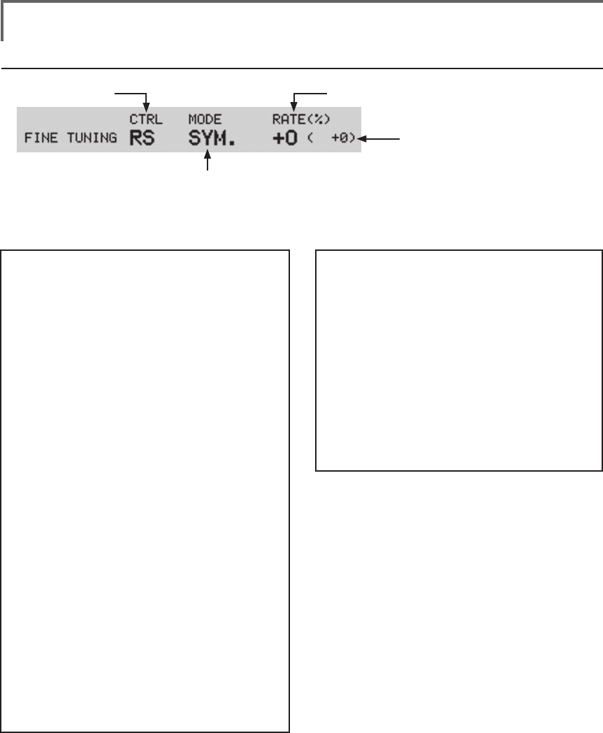
167
<Data>
Operations related to ne tuning VR
●VR selection ●Rate adjustment
(Fine tuning VR operation position)
●Operation mode selection
*The operation modes which can be
selected depend on the function.
[Fine tuning VR operation mode]
[LIN.] Mixing rate 0% at center of VR.
When the VR is turned clockwise and
counterclockwise, the mixing rate
increases and decreases, respectively.
[ATL+] Mixing rate 0% at left end of VR.
When the VR is turned, the mixing rate
increases.
[ATL-] Mixing rate 0% at right end of VR.
When the VR is turned, the mixing rate
increases.
[SYM.] When the VR is turned to the left or
right of the neutral position, the mixing
rate increases.
[Setting method]
1. Control selection
Use the touch sensor to move the cursor
(reverse-video) to the [CTRL] item and
touch the RTN button to call the selection
screen.
Move to the control you want to set by
turning the touch sensor to the left or right
and touch the RTN button.
2. Mode selection
Use the touch sensor to move the cursor to
the [MODE] item and touch the RTN button
to switch to the data input mode.
Turn the touch sensor to the left or right and
switch to the operation mode ([LIN.], [ATL+],
[ATL-], or [SYM.]) corresponding to the set
control and touch the RTN button.
3. Rate adjustment
Move the cursor to the [RATE] item and
touch the RTN button to switch to the data
input mode.
Turn the touch sensor to the left or right and
set the rate.
Initial value: 0%
Adjustment range: -100%~+100%
(When the RTN button is touched for 1 second, the rate is
reset to the initial value.)
Touch the RTN button to end adjustment
and return to the cursol move mode.
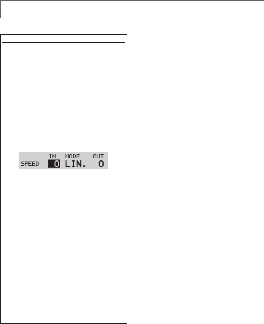
168 <Data>
Operations related to servo speed
Servo speed setting
The servo speed at each function operation
(including flight condition switching) can be
adjusted. The servos operate smoothly at a
fixed speed corresponding to the set speed. The
operating speed (IN side) and return speed (OUT
side) can be set individually.
Switch the operation mode according to the set
function.
"SYM." mode: Used with ailerons and other
self neutral functions.
"LIN." mode: Used with functions which hold
the operation position of the throttle and
switch channel, etc.
[Setting method]
1. Use the touch sensor to move the cursor
(reverse-video) to the [MODE] item and
touch the RTN button to switch to the data
input mode.
Turn the touch sensor to the left or right
and switch to the operation mode ("SYM."
or "LIN.") corresponding to the set function
and touch the RTN button.
2. Move the cursor to the direction ([IN] or
[OUT]) item you want to set and touch
the RTN button to switch to the data input
mode.
Turn the touch sensor to the left or right and
set the speed.
Initial value: 0
Adjustment range: 0~27 (maximum delay)
(When the RTN button is touched for 1 second, the servo
speed is reset to the initial value.)
Touch the RTN button to end adjustment
and return to the edit mode.
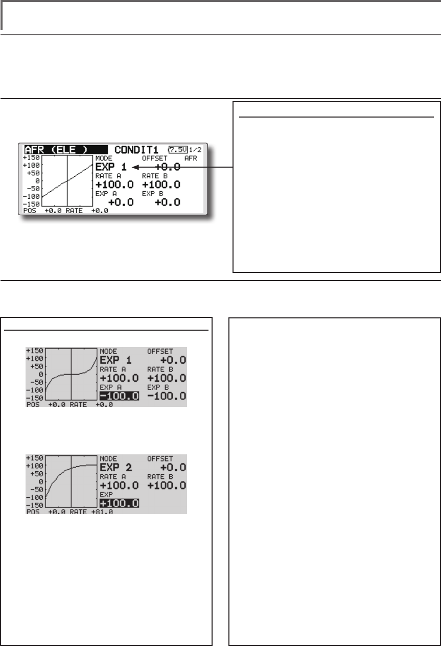
169
<Data>
Curve setting operation
This section describes the setting procedure of curves which are used with the AFR function and each
mixing function.
Curve type selection
Three types of curves (EXP1, EXP2 and
POINT) can be selected.
Curve type selection
1. Use the touch sensor to move the cursor
(reverse-video) to the [MODE] item and
touch the RTN button to switch to the
data input mode.
2. Display the curve you want to use by
turning the touch sensor to the left or
right.
*The curve type blinks.
3. When the RTN button is touched, the
curve type is changed. (Operate the
touch sensor or S1 button to stop the
change.)
[EXP1]: EXP1 curve
[EXP2]: EXP2 curve
[POINT]: point curve
Setting by curve type
When the curve type is selected as described above, adjustment items corresponding to the curve type
appear on the screen. Adjust each curve as described below.
[EXP A], or [EXP B] setting item and touch
the RTN button to switch to the data input
mode.
2. Set the rate by turning the touch sensor to
the left or right.
Initial value: +100.0% (rate)/+0.0% (EXP
rate)
*Initial value differs depending on function.
Adjustment range: -200.0~+200.0% (rate)/-
100.0~+100.0% (EXP rate)
(When the RTN button is touched for 1 second, the rate is
reset to the initial value.)
Touch the RTN button to end adjustment
and return to the cursol move mode.
[Offsetting the curve horizontally in the
vertical direction]
1. Use the touch sensor to move the cursor
(reverse-video) to the [OFFSET] setting item
and touch the RTN button to switch to the
data input mode.
2. Move the curve in the vertical direction by
turning the touch sensor to the left or right.
Initial value: +0.0%
(When the RTN button is touched for 1 second, the rate is
reset to the initial value.)
Touch the RTN button to end adjustment
and return to the cursol move mode.
EXP1/EXP2 curve adjustment
(EXP1 curve)
Using the EXP1 curve is effective in smoothing
starting of the ailerons, elevator, rudder, etc.
(EXP2 curve)
Using the EXP2 curve is effective in engine
rise and other engine control.
The curve left and right rates ([RATE A],
[RATE B]) and EXP curve rate ([EXP A], [EXP
B]) can be adjusted individually. ([EXP] for
EXP2)
The curve can also be offset horizontally
([OFFSET]) in the vertical direction.
[Rate setting]
1. Use the touch sensor to move the cursor
(reverse-video) to the [RATE A], [RATE B],
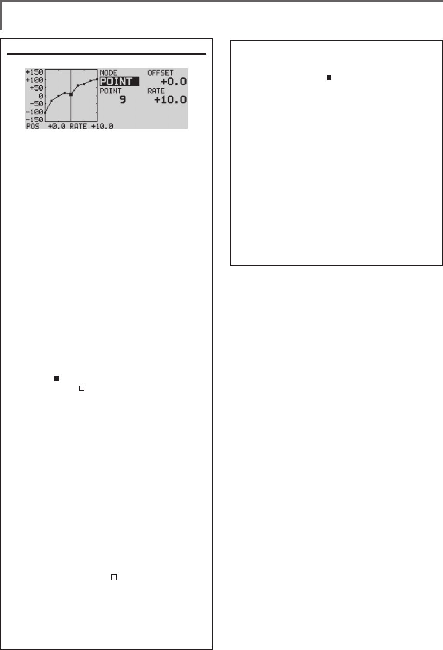
170 <Data>
Point curve (POINT) adjustment
(Point)
Up to 11 or 17 points curve can be used.
(differs with functuion)
Initial point number: 9 points (17 points
curve), 11 points (11 points curve)
*The set points can be freely increased, decreased, and
offset.
[Rate adjustment of each point]
1. Use the touch sensor to move the cursor
(reverse-display) to the [POINT] or [RATE]
item and touch the RTN button to switch
to the curve setting mode.
*It is changed from the reverse-display to the square box
display.
*In this mode, touch the RTN button to switch the [POINT]
item and [RATE] item alternately.
2. Move the cursor (square box) to the
[POINT] item by touching the RTN button.
3. Turn the touch sensor to the left or right
and select the point whose rate you want
to set.
*The mark on the curve shows the currently selected
point. The mark on the curve shows the currently
deleted point.
4. Move the cursor (square box) to the [RATE]
item by touching the RTN button and set
the rate by turning the touch sensor to the
left or right.
Repeat steps 2 through 5 and adjust the
curve.
Push the S1 button to end adjustment and
return to the cursor move mode.
[Point addition]
1. In the curve setting mode, touch the RTN
button to move the cursor to the [POINT]
item and turn the touch sensor to the left
or right and move the cursor on the curve
to the position (mark ) you want to add.
2. When the RTN button is touched for 1
second, the point is added.
[Point deletion]
1. In the curve setting mode, touch the RTN
button to move the cursor to the [POINT]
item and turn the touch sensor to the left or
right and move the cursor on the curve to
the position (mark ) you want to delete.
2. When the RTN button is touched for 1
second, the point is deleted.
[Offsetting the curve horizontally in the
vertical direction]
1. Use the touch sensor to move the cursor
(reverse-video) to the [OFFSET] item.
2.
Move the curve in the vertical direction by
turning the touch sensor to the left or right.
Initial value: +0.0%
(When the RTN button is touched for 1 second, the curve is
reset to the initial value.)
Touch the RTN button to end adjustment
and return to the cursol move mode.
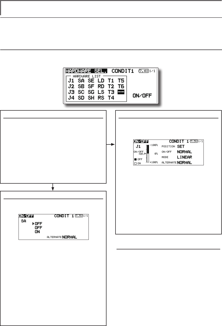
171
<Data>
Switch selection method
The various functions used in the T18SZ can be selected by switch. The switch (including when stick,
trim lever, or VR are used as a switch) setting method is common to all functions.
Switch selection
When a switch is selected at a mixing function, etc., the selection screen shown below is called.
(Switch selection screen example)
When switch was selected
When switch was selected, ON/OFF position
setting is also performed.
*The ON/OFF setting state of each position is displayed.
1. When you want to change the ON/OFF
setting, use the touch sensor to move the
cursor and touch the RTN button to switch
to the data input mode. Switch the ON/
Off display by turning the touch sensor to
the left or right.
*ON/OFF display blinks.
3. When the EDIT button is pressed, the ON/
OFF setting is changed. (Operate the
touch sensor or S1 button to stop the
change.)
4. To return to the preceeding screen, move
the cursor to the [ON/OFF] at the top of
the screen and touch the RTN button.
When stick, trim lever, or knob selected
When a stick, trim lever, or knob is used as a
switch, four operation modes can be selected by
the following mode and type combination:
1. When you want to change the mode,
move the cursor to [MODE] and touch
the RTN button to switch to the data input
mode. Switch the display to the mode
you want to change by turning the touch
sensor to the left or right and then make
the change by touching the RTN button.
●
Mode: [LINEAR]/[SYMMETRY]
*
Set the ON/Off point by the method described on the next page.
Switch selection
1. Use the touch sensor to move the cursor
(highlights) to the switch you want to
select and touch the RTN button.
*The switch blinks.
2. To return to the preceeding screen, move
the cursor to the [HARDWARE SEL.] at
the top of the screen and touch the RTN
button.
Or, move the cursor to the [ON/OFF] and
call the ON/OFF position setting screen by
touching the RTN button.
Alternate mode setting
●
Mode: [NORMAL]/[ALTERNATE]
1. Move the cursor to the [ALTERNATE] item
and touch the RTN button to switch to the
data input mode.
2. Change to the mode you want to set by
turning the touch sensor to the left or right.
*The mode display blinks.
3. Touch the RTN button. (Operate the touch
sensor or S1 button to stop the change.)
4. To return to the preceeding screen, move
the cursor to the [ON/OFF] at the top of the
screen and touch the RTN button.
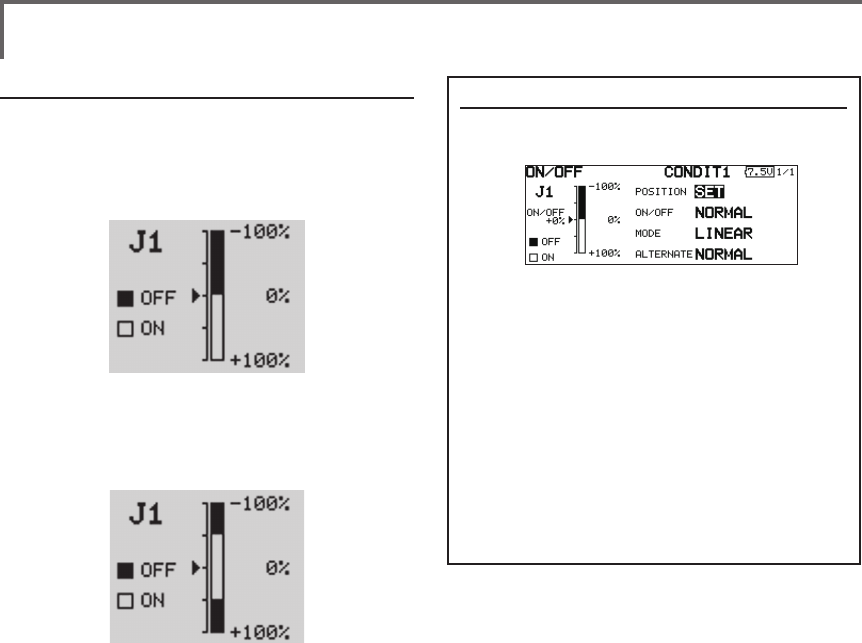
172 <Data>
Operation modes
The operation modes when stick, trim lever, or
knob was selected are described below.
Linear mode
This mode sets ON/OFF at the left or right (up or
down) with the set point as the reference.
Symmetrical mode
Left and right (up and down) operations are
symmetrical about the neutral position. For
instance, when you want to switch DR1 with the
aileron stick, when the stick is moved to the left or
right, DR1 can be turned on at the same left and
right position.
Shifting the ON/Off point
The ON/OFF point can be shifted. ON/OFF
at a free position can be changed.
●Black range: OFF range
●White range: ON range
[Setting method]
1. First, use the touch sensor to move the
cursor to the [POSITION] item.
2. Move the stick, trim lever, or knob to the
point you want to change and touch the
RTN button. The point is shifted.
3. To return to the preceeding screen, move
the cursor to the [ON/OFF] at the top of
the screen and touch the RTN button.
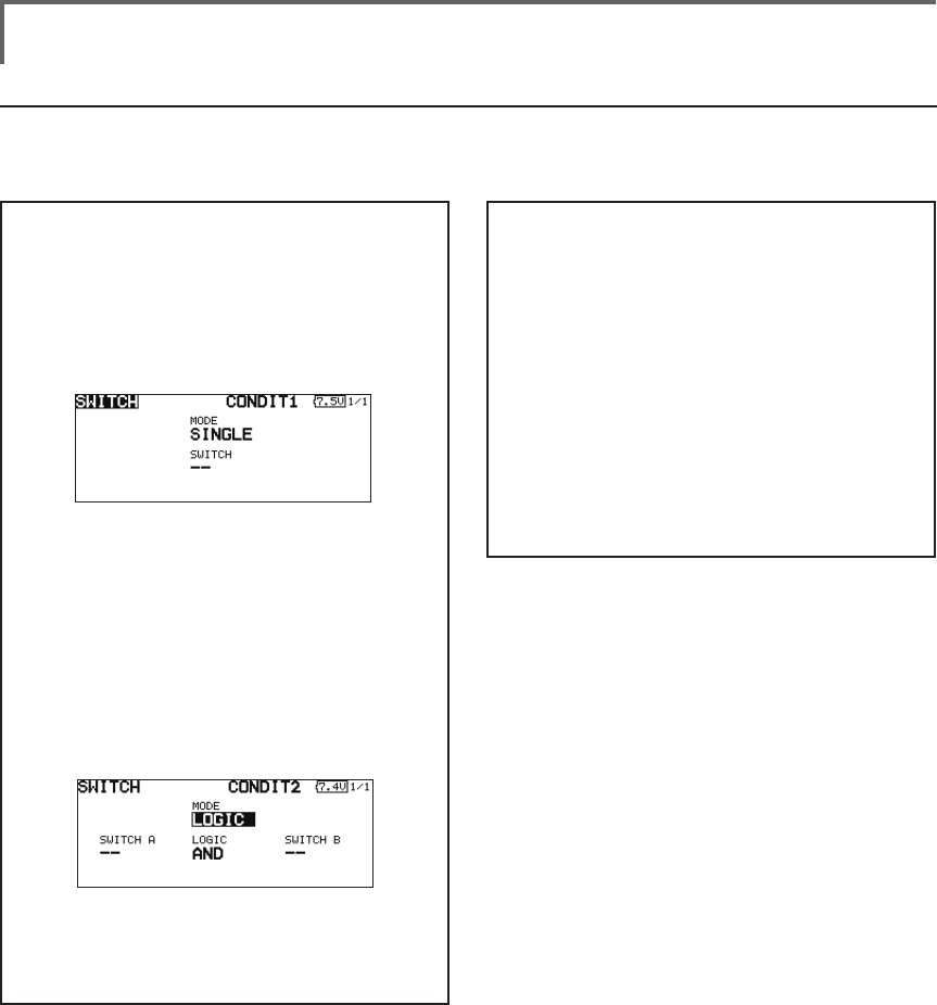
173
<Data>
Logic mode
AND: When both switches are ON, the
condition is ON.
OR: When either switche is ON, the
condition is ON.
EOR: When the two switches are in different
states, the condition is ON.
Switch mode selection
1. Move the cursor to the [MODE] item and
touch the RTN button to switch to the data
input mode.
2. Turn the touch sensor to the left and select
the [LOGIC].
*[LOGIC] display blinks.
3. Touch the RTN button to change to the
logic switch mode.
(Logic switch setting screen)
Swich selection
1. Select the switch A and B. (Refer to the
description at the previous page.)
Logic mode selection
1. Move the cursor to the [LOGIC] item and
touch the RTN button to switch to the data
input mode.
2. Turn the touch sensor to the left or right and
select the logic mode.
*The mode display blinks.
3. Touch the RTN button to change to the
logic mode.
4. To return to the preceeding screen, move
the cursor to the [SWITCH] at the top of the
screen and touch the RTN button.
Logic switch (Condition Select function only)
The logic switch function lets you turn operation on and off by combining two switches. For instance,
the condition is activated when 2 switches are turned on.
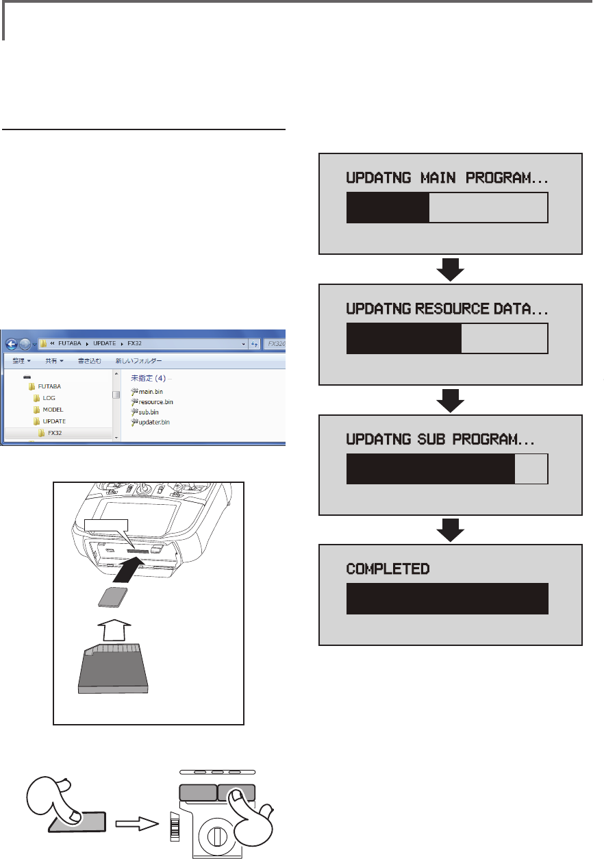
174 <Data>
UPDATING
Your Futaba T18SZ transmitter programming can be updated easily online. When functions are added or
improved, the update le can be downloaded from our website. Copy the update les to the SD card and
then use the following procedure to update the program.
Check our web site for the FAQ regarding updating for more information.
Updating procedure
Note: If the battery fully discharges during
program updating, updating will fail. When
the remaining battery capacity is 50% or
less, always recharge the battery before
updating.
Note: The model data in the transmitter can
be used unchanged after updating, but to
be safe, back up the model data before
updating.
1. Copy update files to a SD card. Typical
structure of folders of the card for update
are following.
2. Attach the SD card into the SD slot of the
T18SZ.
3. Press the Home/Exit switch and turn on the
power switch, and T18SZ should begin to
update.
4. When updating is complete, the screen
shown below appears.
5. Turn off the power switch. After the monitor
LED goes off, switch the update switch in the
down direction.
After the updating above has been
completed, turn on the power and then
check the system program version at the
system menu information screen.
6. If writing goes wrong, the following error
message will come out.
"LOW BATTERY"
"UPDATE FILE NOT FOUND"
"BROKEN FILE"
"WRITE ERROR"
Removable disk (E:)
① A battery cover is opened.
② It inserts until it locks SD card into SD card slot.
*It is releasable if a card is pushed once again.
*Don't mistake the
both sides/ the
direction of
SD card.
SD card slot
U.menu/Mon
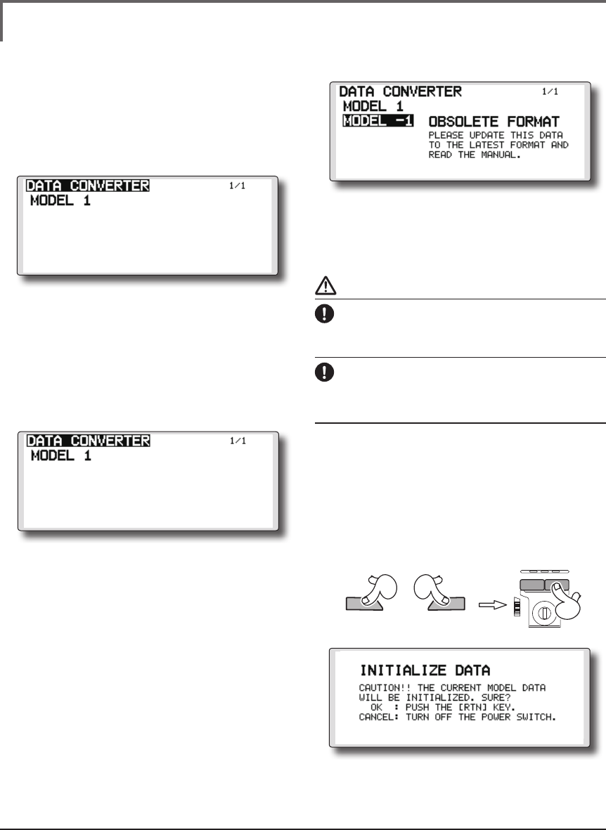
175
<Data>
FUTABA CORPORATION Phone: +81 475 32 6982, Facsimile: +81 475 32 6983
1080 Yabutsuka, Chosei-mura, Chosei-gun, Chiba-ken, 299-4395, Japan
©FUTABA CORPORATION 2015, 5 (1)
FX-30/T12FG →T18SZ MODEL DATA CONVERSION
The model data (only latest version) of FX-30/T12FG can be copied to T18SZ.
* The card reader of a personal computer, SD card, and CF card is required.
* The model data of T18SZ cannot be copied to FX-30/T12FG.
[Model data conversion method]
1. Attach a SD card that contains model data
of T12FG or FX-30 to the SD slot of a T18SZ.
2. Turn on the power switch, and the Data
Converter should run.
3. The converter shows a list of model data
in the card. Select a model data that you
want to convert and push "RTN" key, and
the converter should begin converting data.
4. If the convert succeeds, the converter will
show the following message. The converted
data are copied to the internal memory of
the T18SZ. Hence, if the T18SZ does not have
free spaces of its internal memory, converts
must fail.
5. The converter can accept model data
made by T12FG or FX-30 with the latest
software (Ver.3.0) only. If you try to convert
model data made by old version software,
the converter must fail to convert and show
the following error message. If this message
is shown, do the following procedure to
update the model data in order to avoid
this limitation.
(a) First, update a T12FG or FX-30 to the latest software (Ver. 3.0).
(b) Load the model data failed to convert into the T12FG or FX-30
with the latest software, and the model data should be updated
to the latest format.
(c) Save the updated model data to a SD card.
(d) Retry to convert the updated model data on a T18SZ.
* When SD card cannot be recognized, it may be able to be used
if it reformats by SD formatter offered from SD Association.
SD formatter is downloadable from SD Association (https://
www.sdcard.org/).
(As of January, 2013)
CAUTION
After the completion of a data copy should fully
perform a check of operation on the model to
be used.
Check well all the directions of operation and
all the operation switches.
Compulsive reset of data *Usually, it is not used.
Operation will become unusual if imperfect
model data should be read.
In that case, the forcible reset of the model data
can be carried out by the following method.
[Model data compulsive reset method]
1. First, "HOME/Exit" and "U.menu/Mon" are
pushed. The power supply of T18SZ is then
turned on.
2. A "INITIALIZE DATE" screen comes out. "RTN"
will be pushed if forcible reset is carried out.
In a stop, a power supply is turned off.
HOME/Exit U.menu/Mon