Futaba T4GRS-24G Radio Control User Manual Part 1
Futaba Corporation Radio Control Part 1
UserManual.wiki
>
Futaba
>
T4GRS-24G User Manual
>
User Manual Part 1
Contents
1.
User Manual Part 1
2.
User Manual Part 2
3.
User Manual Part 3
User Manual Part 1
Navigation menu
Upload a User Manual
Namespaces
Wiki Guide
HTML
PDF
Info
Views
User Manual
Discussion / Help
Navigation
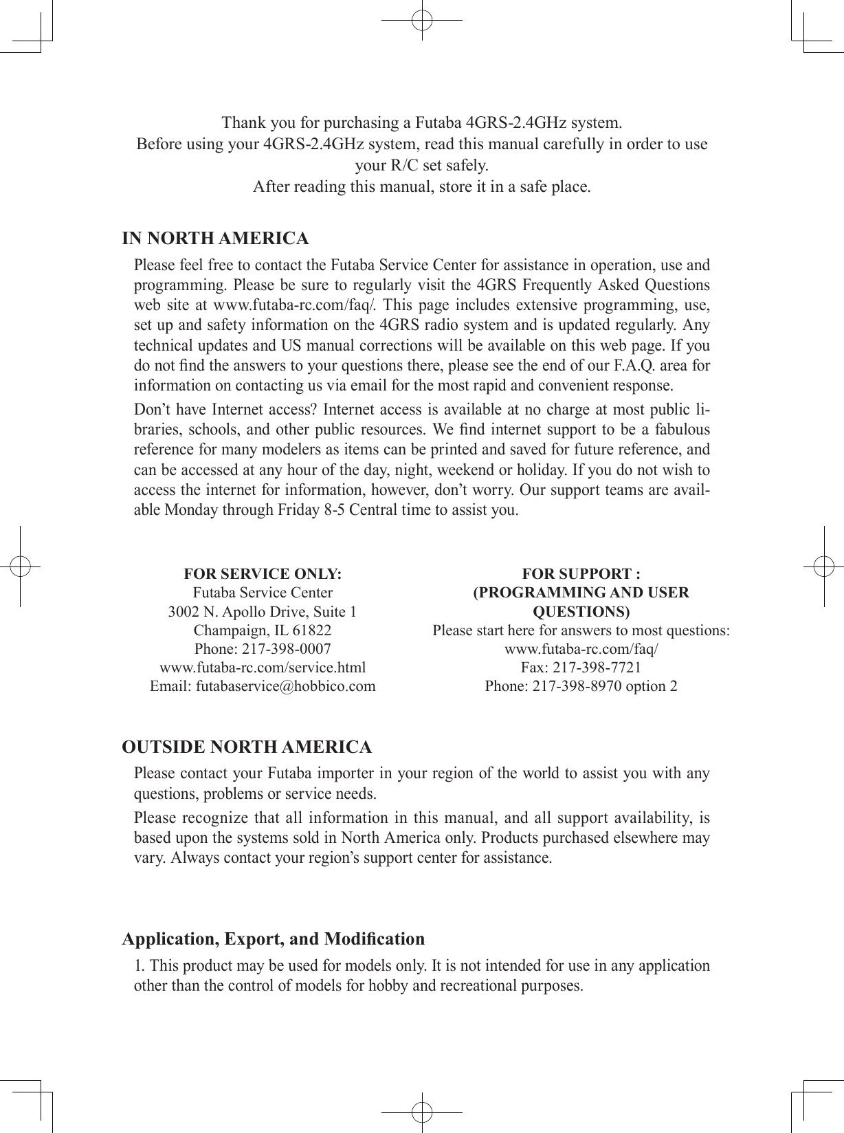
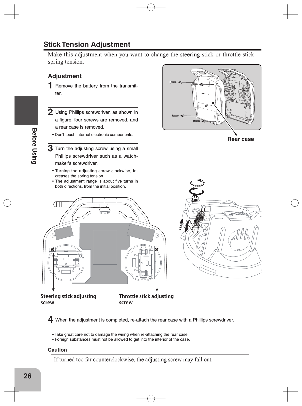
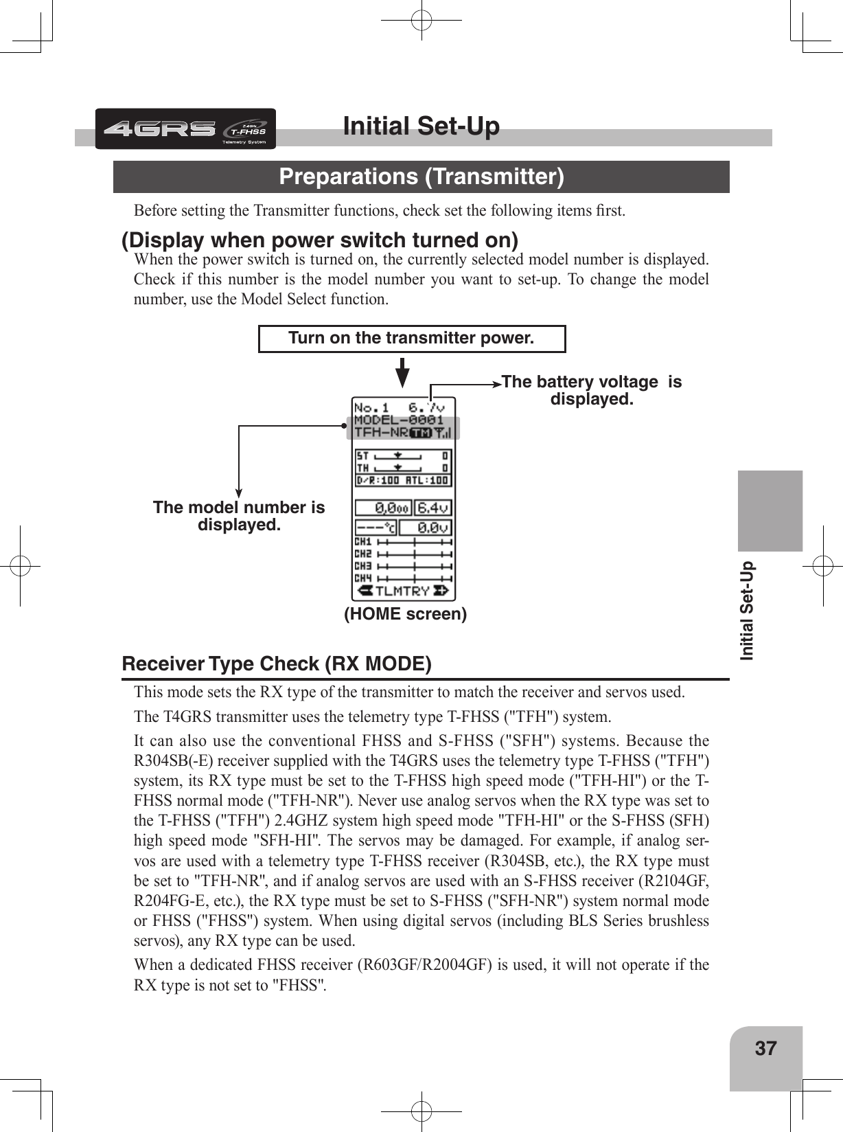
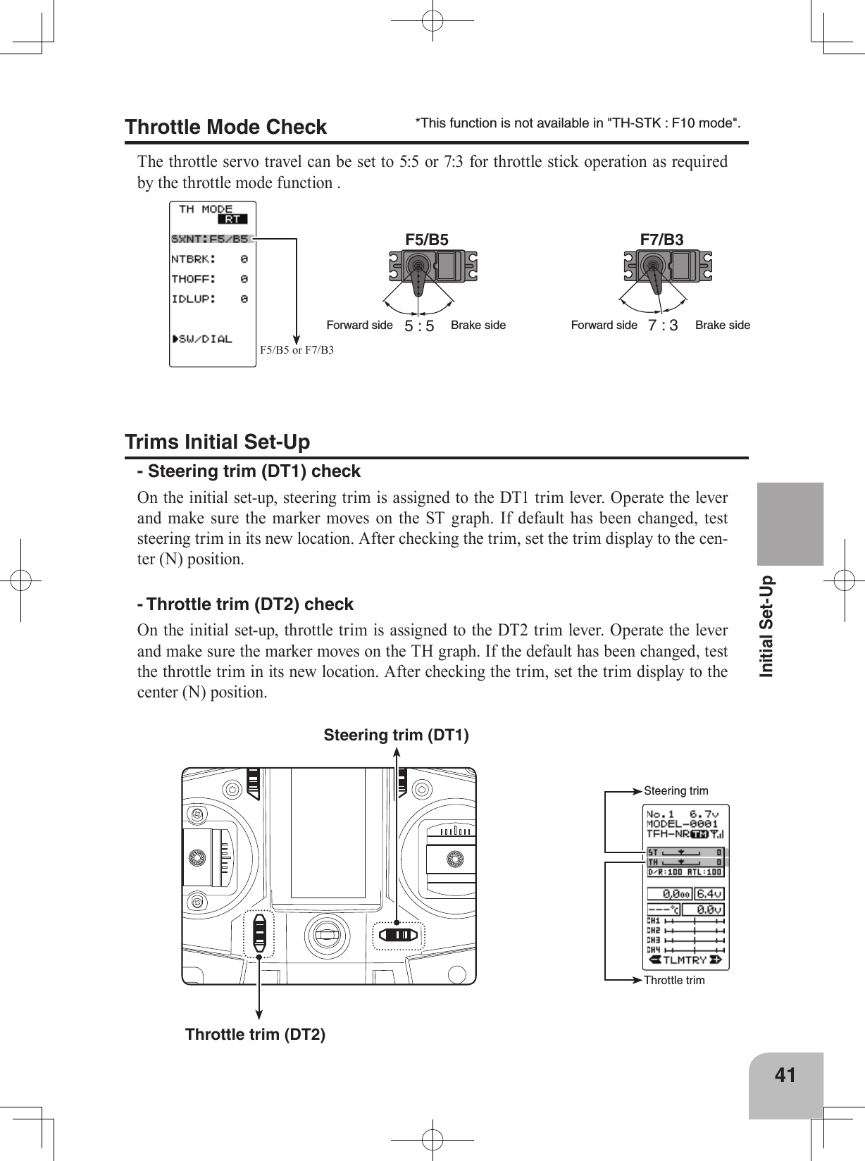
![27Before UsingHigh sideBrake (reverse) sideStroke can be reduced mechanically.Stick stroke adjustment1Make this adjustment by turning the adjusting screw above the stick with a Phillips screwdriver.• When the adjusting screw is turned counter clockwise, the stroke is reduced.Mechanical Throttle Stick Stroke AdjustmentMake this adjustment when you want to reduce the throttle stick range at the full power or brake/reverse positions.2On the MENU2 screen, select the setting item "ADJUSTER" using the (JOG) button, and pressing the (JOG) button.3(Selection of THROTTLE)Move the cursor to "THROTTLE" using the (JOG) button up or down function, and pressing the (JOG) button.HOME MENU1PushADJUSTER*STEERING[ RT ]*THROTTLEMENU2Select ADJUSTERSelect THROTTLEKeyCANCELADJUSTERTHROTTLEN5 5KeyCANCELADJUSTERTHROTTLEN5 5N7 3KeyCANCELADJUSTERTHROTTLEN5 5N7 3BRKFWDKeyCANCELADJUSTERTHROTTLEN5 5N7 3BRKFWDfig-1fig-3fig-2fig-44 (Throttle 5:5 neutral adjustment )Neutral adjuster is set to 5:5 the Neutral Adjuster switch (see next page). In the 5:5 neutral setup screen (fig-1) state, pull the stick back slightly then allow to return to neutral and press the (JOG) button whilst ensuring the stick is not touched.5 (Throttle 7:3 neutral adjustment )Neutral adjuster is set to 7:3 by the Neutral Adjuster switch (see next page). In the 7:3 neutral setup screen (fig-2) state, pull the stick back slightly then allow to return to neutral and press the (JOG) button whilst ensuring the stick is not touched.Note that both the 5:5 and 7:3 neutral adjustment procedures have to be completed as part of the set-up process. Once com-plete the required option should be selected. 6 (Throttle throw adjustment)In the throw setup screen state (fig-3), gently move the stick fully to the brake /reverse and full power positions and when button Push](https://usermanual.wiki/Futaba/T4GRS-24G.User-Manual-Part-1/User-Guide-2495374-Page-26.png)
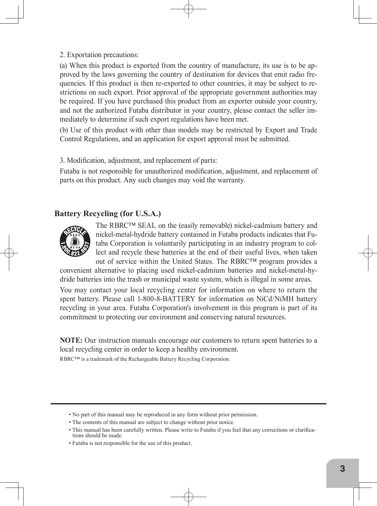
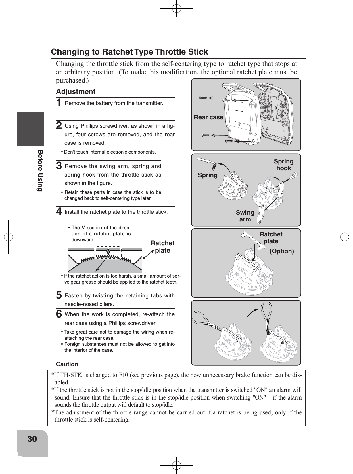
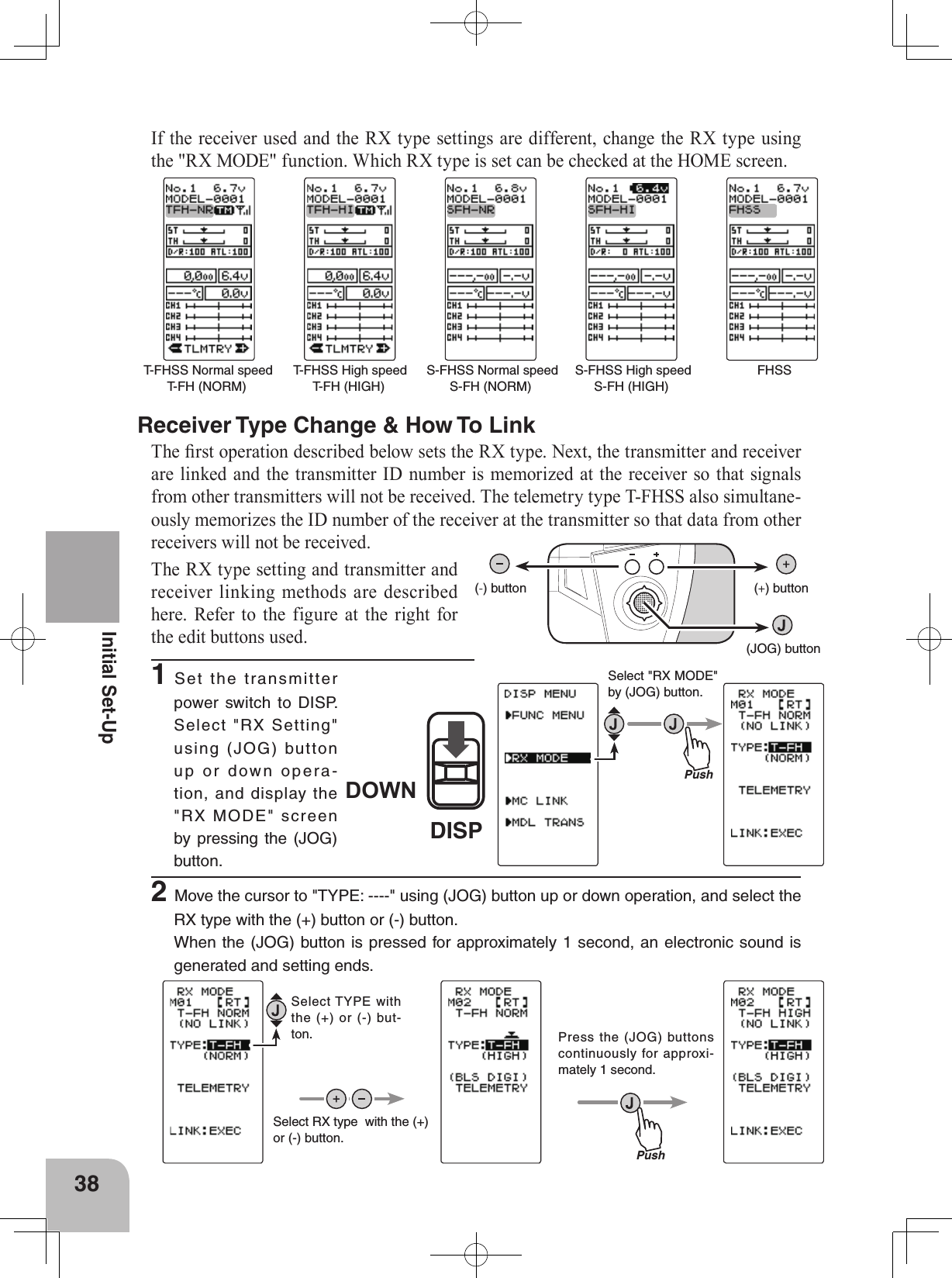
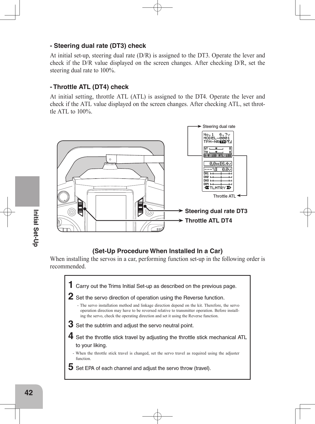
![28Before UsingNeutral AdjusterNeutral Adjuster OperationThe neutral adjuster selects the throttle stick neutral position.55731Neutral adjuster is set to 5 : 5 when in the upper position. It will be set to 7 : 3 when moved to the lower position• If 7 : 3 is used, the neutral to full power stick range is increased.mark (fig-4) is displayed, pressing the (JOG) button.An internal check is performed automatically. When each adjust-ment point is within a fixed range, correction is performed and "COMPLETE!" (fig-5) is displayed.If an adjustment point is not within a fixed range, correction is not performed and the correction data is not updated.If the stroke is made too narrow, this will cause an error.In that case, extend the stroke.7When complete, return to the ADJUSTER screen by press the (JOG) button. 8Next, move the cursor to [RT] by the (JOG) button, and press the (JOG) button. KeyCANCELADJUSTERTHROTTLEN5 5N7 3BRKFWDCOMPLETE!fig-5CautionWhen the stroke is adjusted, the throttle servo travel should also be adjusted elec-tronically. If the stroke is mechanically reduced too far the adjusting screw may fall out. When a neutral adjuster change is made, be sure to carry out system change. Caution2On the MENU2 screen, select the set-ting item "SYSTEM" using the (JOG) button, and press the (JOG) button.](https://usermanual.wiki/Futaba/T4GRS-24G.User-Manual-Part-1/User-Guide-2495374-Page-27.png)
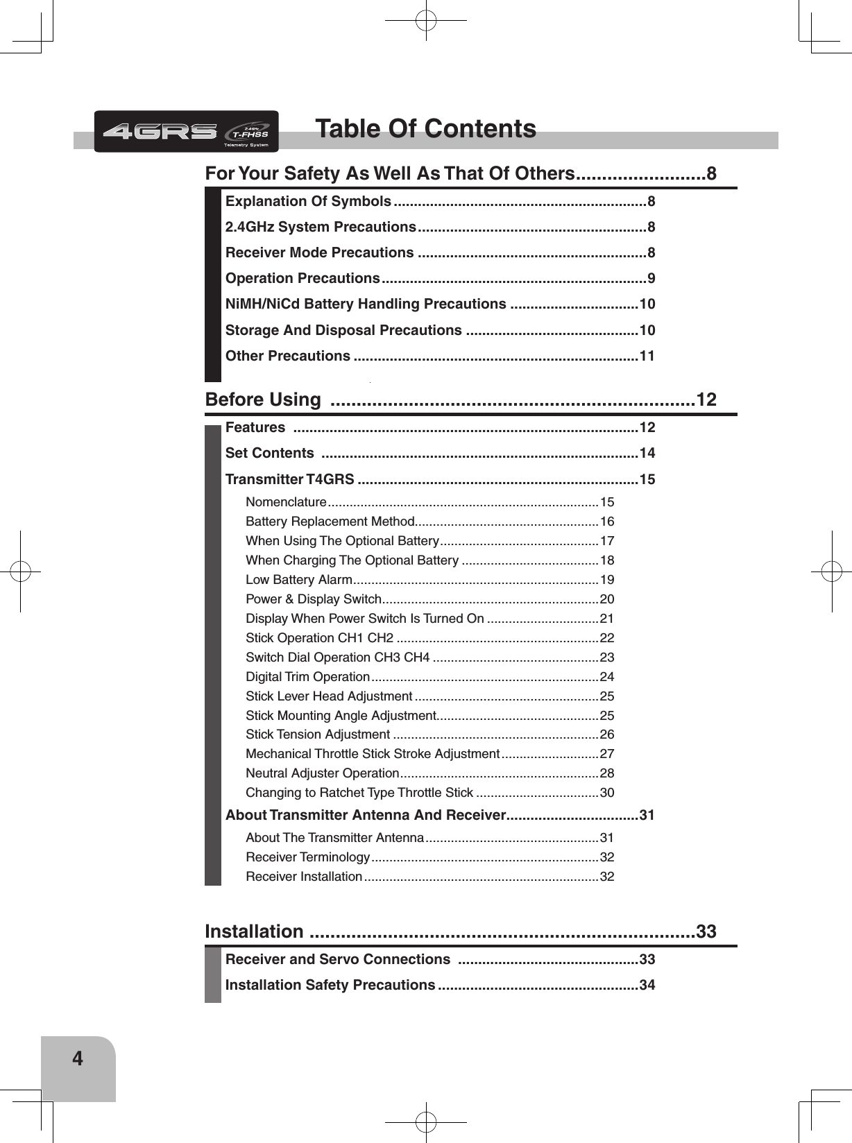
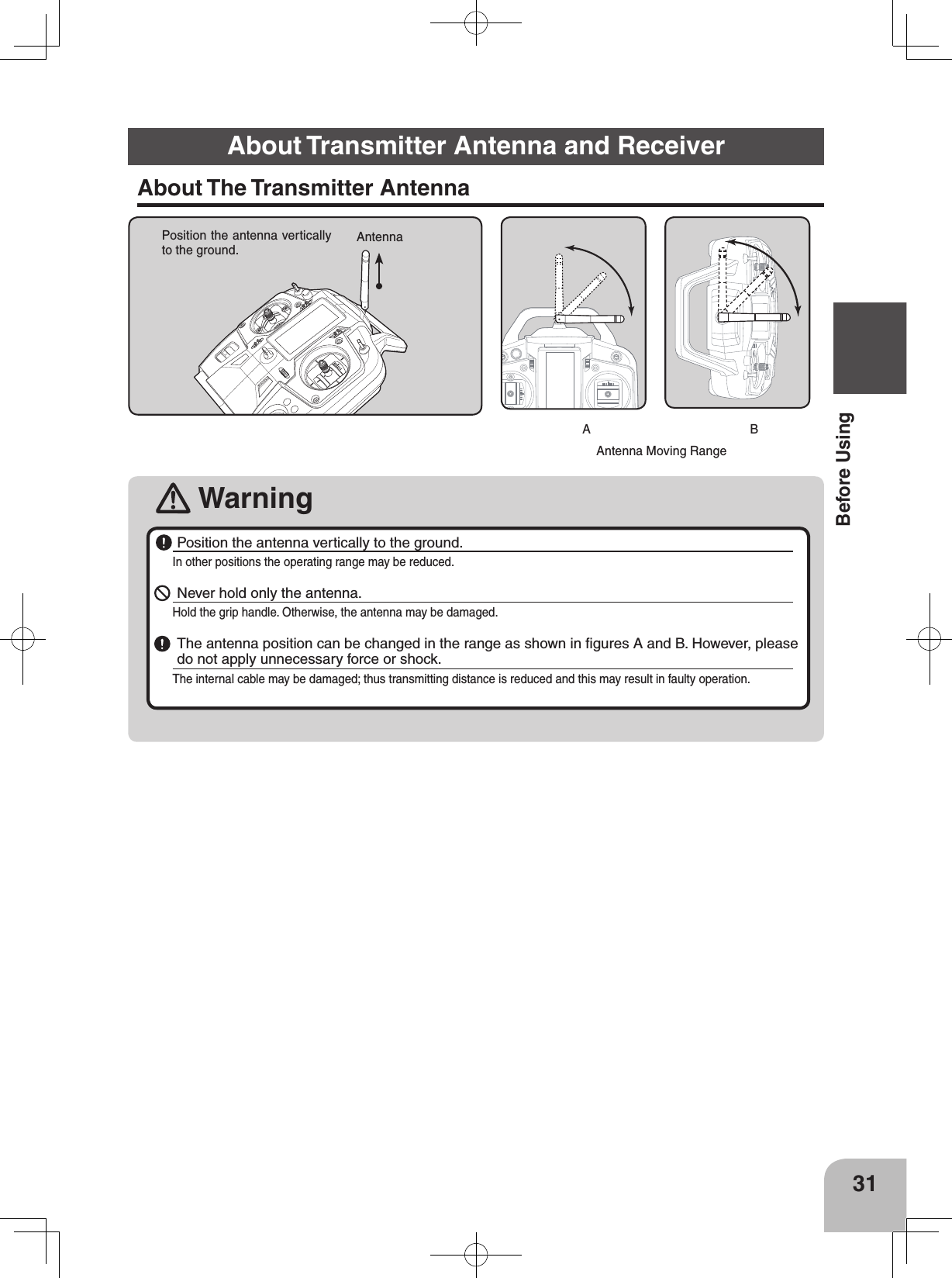
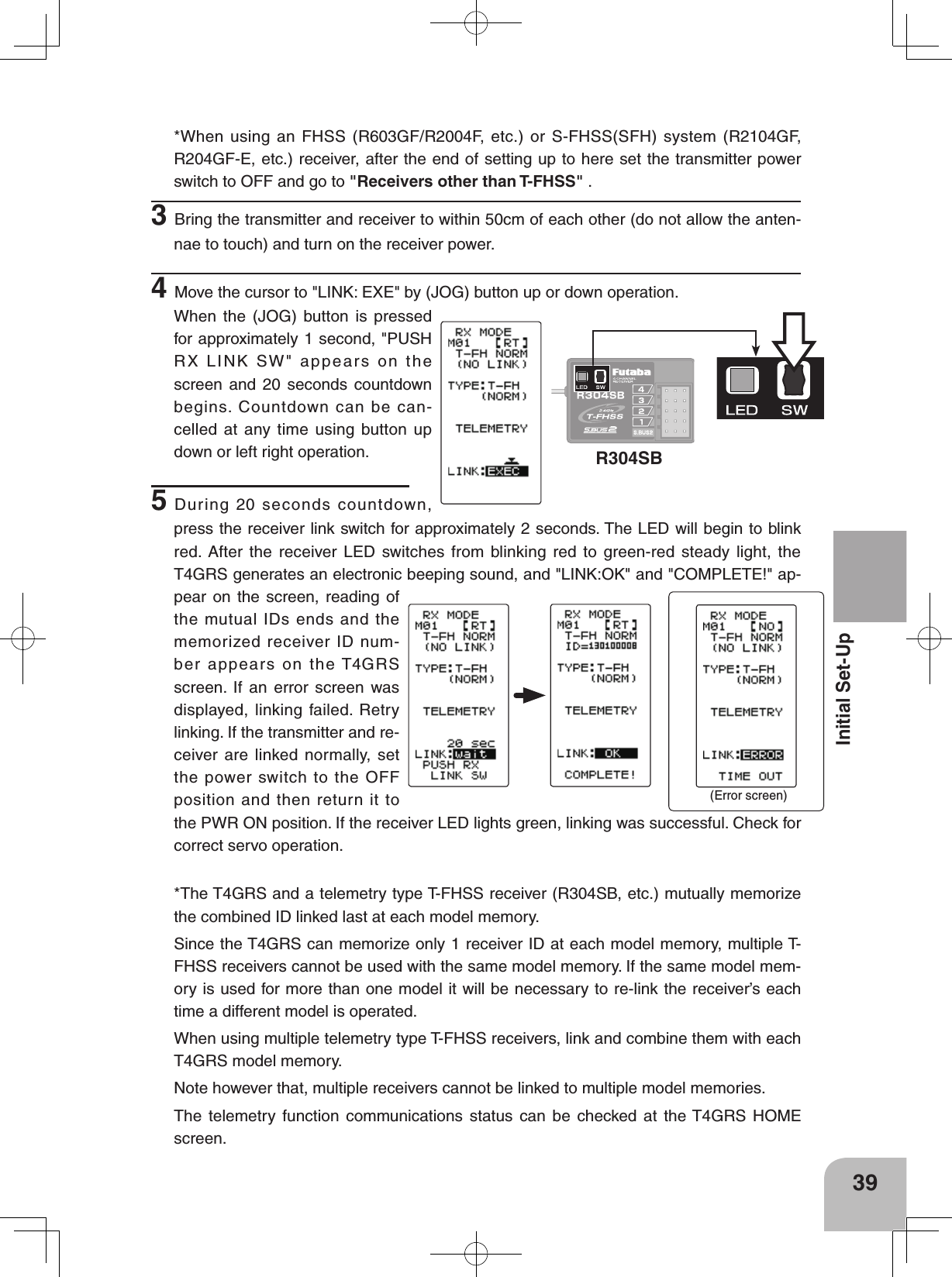
![29Before Using• "F10" should be selected only when using a ratchet on the throttle stick. (for GP boats) UP or DOWNCONTRALHT-TMBK-LHTSYSTEM[ RT ]LHT-PWBAT T DRY4OPE-TMBUZZERMENUTH-STKDISP0ALL10s1565OFFTLMTRENG7 33(Selection of TH-STK)Move the cursor to "TH-STK" using the (JOG) but-ton up or down operation.4 (Selection of your 4GRS neutral position)Use the (+) and (-) buttons to select either 5:5 or 7:3.5(Neutral position execution)Press the (JOG) button for about 1 second. A beeping sound is generated and the neutral position is select-ed.6When completed, return to the MENU2 screen by pressing the (JOG) button. 7Next, move the cursor to [RT] using the (JOG) button, and press the (JOG) button. HOME MENU1PushPushCONTRALHT-TMBK-LHTSYSTEMLHT-PWBATT DRY4OPE-TMBUZZERMENUTH-STKDISP0ALL10s1565OFFTLMTRENG5 5 RT CONTRALHT-TMBK-LHTSYSTEM[ RT ]LHT-PWBAT T DRY4OPE-TMBUZZERMENUTH-STKDISP0ALL10s1565OFFTLMTRENG5 5MENU2Press (JOG) about 1secondSelection of your 4GRS neutral position5:57:3F10 (Next page)](https://usermanual.wiki/Futaba/T4GRS-24G.User-Manual-Part-1/User-Guide-2495374-Page-28.png)
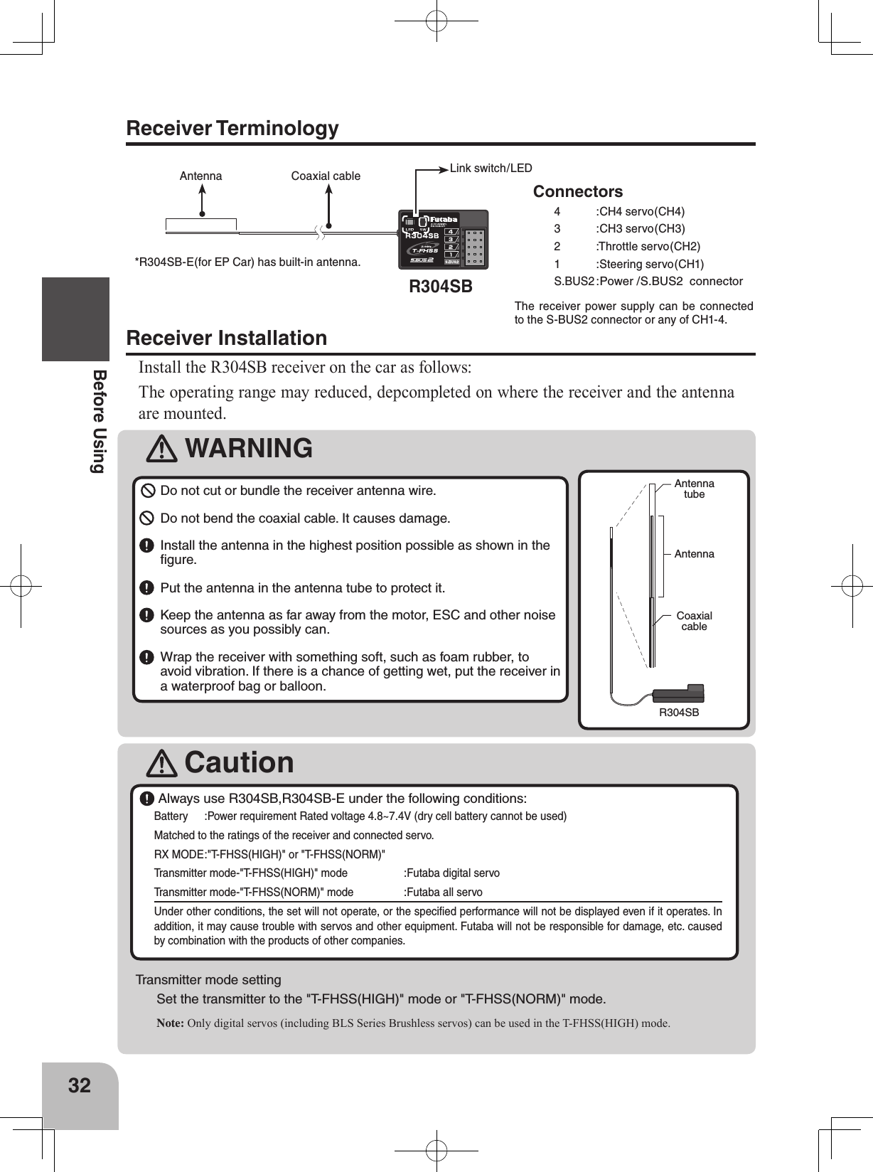
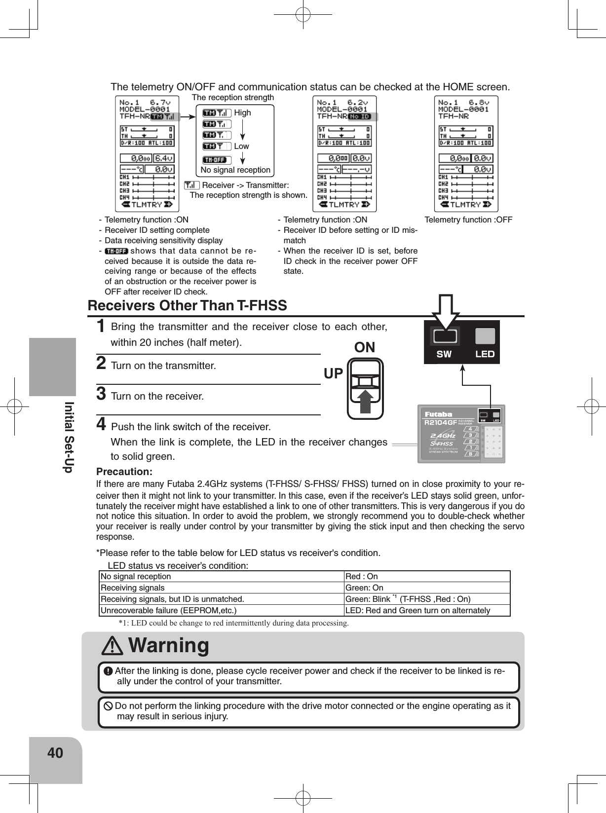
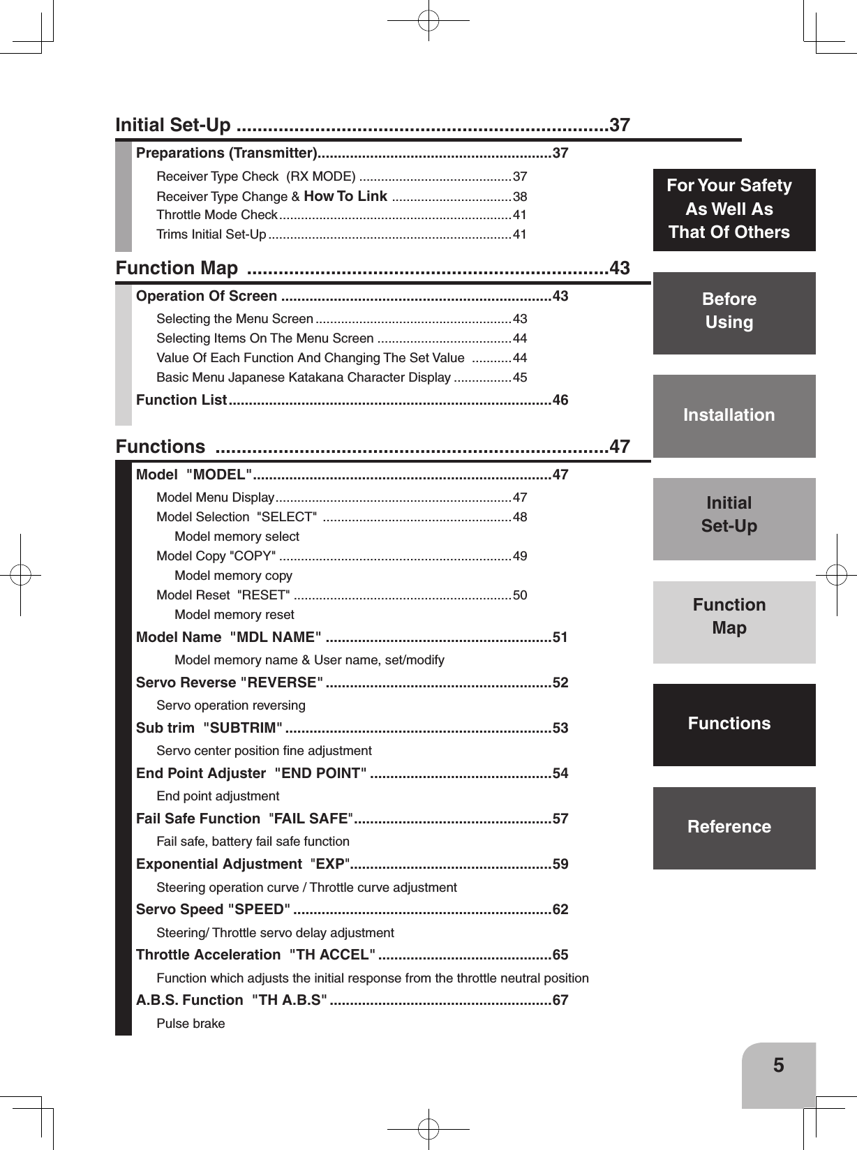
![(+) button is pressedPress (-) button is pressedPress (JOG) button is pressed (+) button (-) button (JOG) buttonPress(JOG) button up(JOG) button down(JOG) button left(JOG) button right(JOG) button up, down, left or right PressPressPressPressPress(DISP MENU screen)(MENU 2 screen)(MENU 1 screen)(HOME screen) On the MENU1 or 2 screen, move the cursor to [RT] by (JOG)button up or down operation and press the button. On the DISP MENU screen, move the cur-sor to "FUNC MENU" by (JOG) button up or down operation and press the button.43Function MapFunction MapOperation Of ScreenIn this instruction manual, Edit Buttons are represented by the symbols shown below.The (JOG) button can be operated in the 4 directions up, down, left, and right.Selecting The Menu ScreenRefer to the map below for the method of displaying the function setting menu screen from the PWR ON initial screen or DISP (display) screen and the method of returning from the menu screen to the PWR ON initial screen or DISP (display) screen.](https://usermanual.wiki/Futaba/T4GRS-24G.User-Manual-Part-1/User-Guide-2495374-Page-42.png)