Futaba T4GRS-24G Radio Control User Manual
Futaba Corporation Radio Control
UserManual.wiki
>
Futaba
>
T4GRS-24G User Manual
>
User Manual Part 2
Contents
1.
User Manual Part 1
2.
User Manual Part 2
3.
User Manual Part 3
User Manual Part 2
Navigation menu
Upload a User Manual
Namespaces
Wiki Guide
HTML
PDF
Info
Views
User Manual
Discussion / Help
Navigation
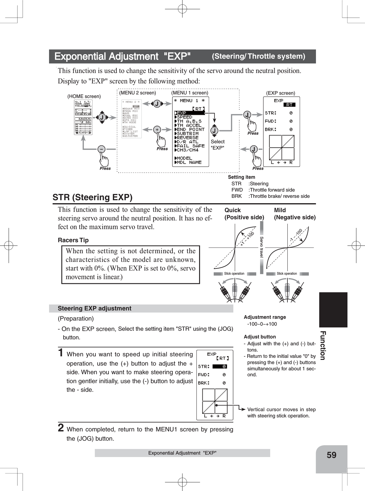
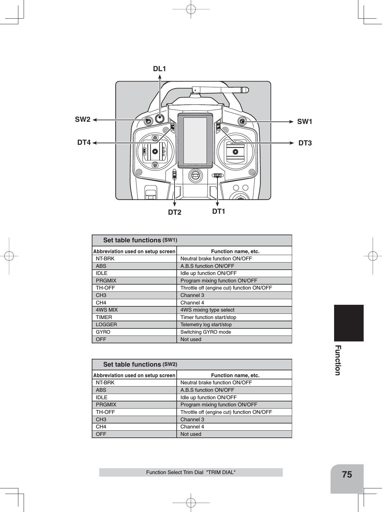
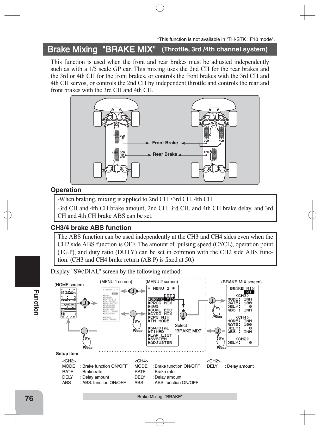
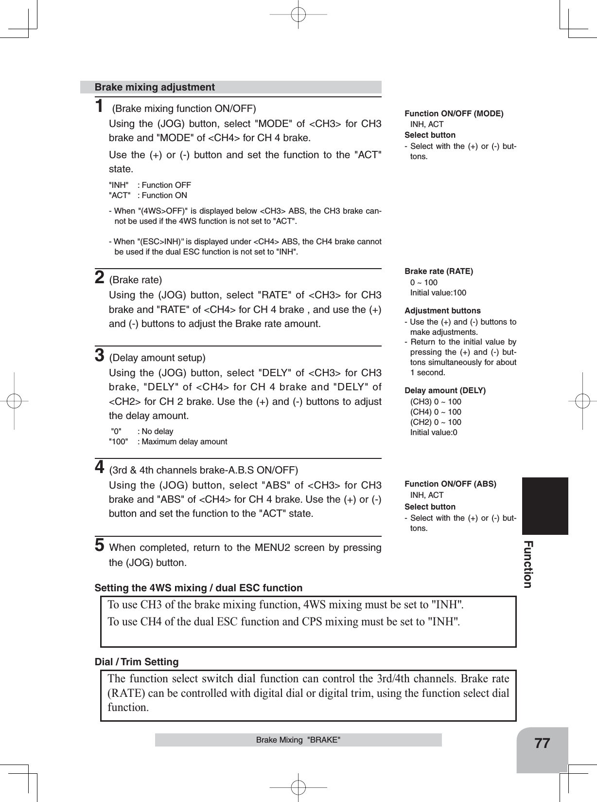
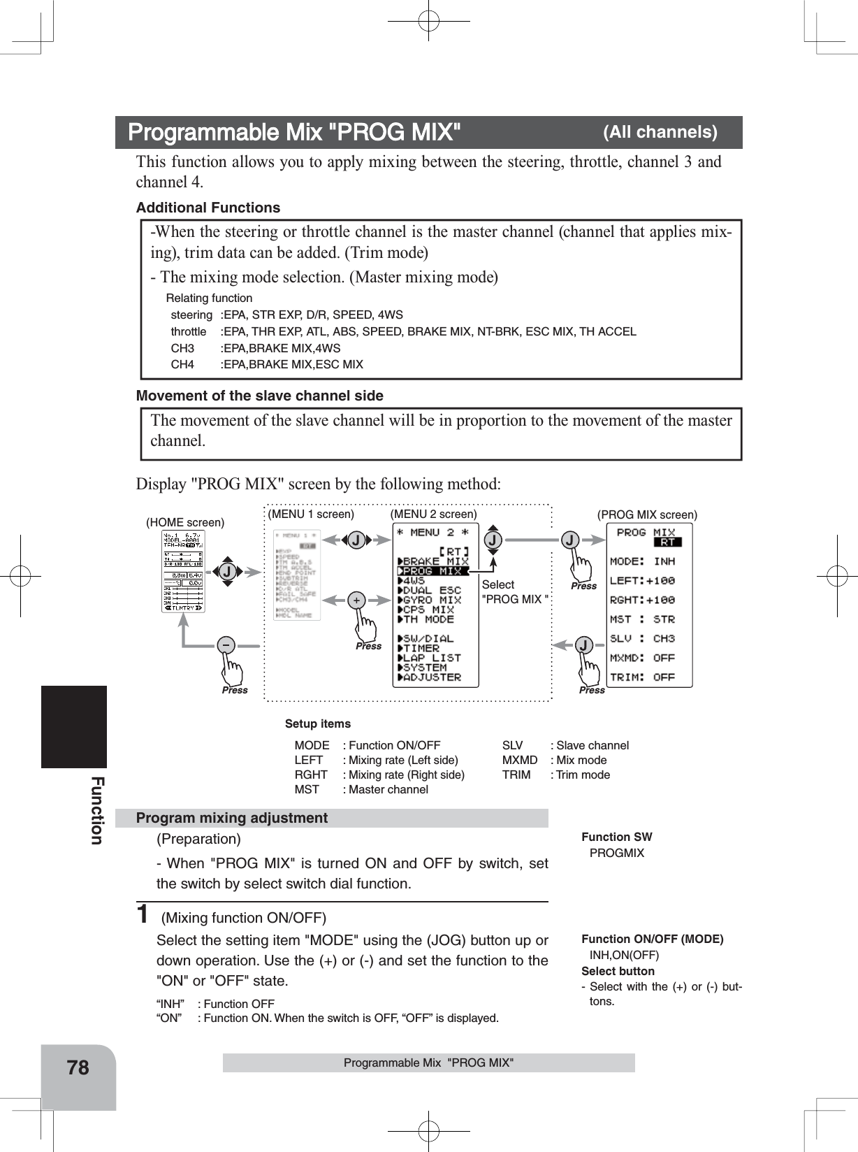
!["KATAKANA" charactersAlphabetic charactersEXPSPEEDTH A.B.STH A.B.STH ACCELEND POINTTRIMREVERSE D/R ATLD/R ATLFAIL SFECH3 /CH4CH3 /CH4MODELMDL NAME MIXBRAKE MIXPROG MIXPROG MIX4WS4WSESCDUAL ESCMIXGYRO MIXCPSMIXCPSMIXTHTH MODESW/SW/DIALTIMERLAP LISTSYSTEMADJUSTER (MENU 2 screen)(MENU 1 screen)(SYSTEM screen)CONTRALHT-TMBK-LHTSYSTEM[ RT ]LHT-PWBATT DRY4OPE-TMBUZZERMENUTH-STKDISP0ALL10s1565OFFTLMTR5 5崓崲CONTRALHT-TMBK-LHTSYSTEM[ RT ]LHT-PWBATT DRY4OPE-TMBUZZERMENUTH-STKDISP0ALL10s1565OFFTLMTR5 5ENG(HOME screen)Call the MENU2 screen from the HOME screen by the (JOG) but-ton up, down, left or right opera-tion and press the (+) button.On the MENU2 screen, move the cursor to "SYSTEM" by the (JOG) button up or down op-eration and press the button.(MENU 2 screen)45Function MapBasic Menu Japanese Katakana Character DisplayOn the system menu, the basic menu screen shown below can be displayed in Japanese katakana characters.On the SYSTEM screen, select MENU by pressing the (JOG) button and select "ENG" or "" by pressing the (+) or (-) button.Changing the character After changing the setting, return to the MENU2 screen by pressing the (JOG) button or return to the HOME screen by se-lecting [RT] and pressing the (JOG) button.](https://usermanual.wiki/Futaba/T4GRS-24G.User-Manual-Part-2/User-Guide-2495375-Page-2.png)
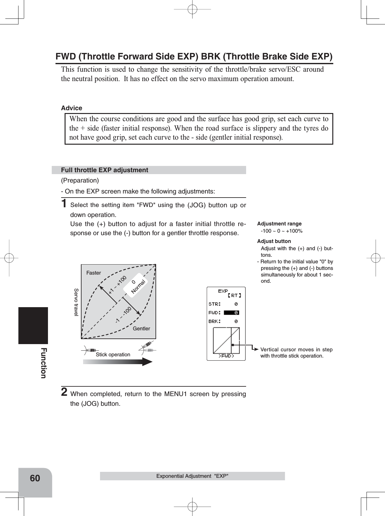
![46Function MapFunction Abbreviation Description Of Function Page NoRX MODE5HFHLYHUW\SHVHOHFWLRQOLQNLQJZLWKWHOHPHWU\W\SH7)+66V\VWHPUHFHLYHU P-37MODEL0RGHOPHPRU\VHOHFW0RGHOPHPRU\FRS\0RGHOPHPRU\UHVHW P-47MDL NAME0RGHOPHPRU\QDPHVHWPRGLI\XVHUQDPHVHWPRGLI\ P-50REVERSEServo reversing P-52SUBTRIM6HUYRFHQWHUSRVLWLRQ¿QHDGMXVWPHQW P-53END POINT(QGSRLQWDGMXVWPHQW P-54FAIL SAFEFail safe, battery fail safe P-57EXP6WHHULQJFXUYHDGMXVWPHQW7KURWWOHFXUYHDGMXVWPHQW P-59SPEEDSteering servo delay/ Throttle servo delay P-62TH ACCELReduces the "lag time" of the throttle from the neutral position. P-65TH A.B.S Pulsing brakeP-67CH3/CH4Channel 3&4 servos operation position set/check P-71D/R ATL6WHHULQJDQJOHDGMXVWPHQWZKLOHUXQQLQJ%UDNHVLGHDGMXVWPHQW P-72SW/DIALSelection of functions operated by switch, digital dial and digital trim P-73BRAKE MIX)URQWDQGUHDULQGHSHQGHQWEUDNHFRQWUROIRU*3FDUHWF P-76PROG MIX3URJUDPPDEOHPL[LQJEHWZHHQVSHFL¿FFKDQQHOV P-784WS MIX:6PL[LQJ P-80DUAL ESC)URQWDQGUHDU(6&VPL[LQJ P-82GYRO ESC7KHVHQVLWLYLW\RI)XWDEDFDUUDWHJ\URVFDQEHDGMXVWHG P-84CPS ESC7KH&36RI)XWDED/('FRQWUROOHUFDQEHDGMXVWHG P-86TH MODEThrottle servo forward side and brake side operation rate setting/ Neutral brake/ Idle up at engine start/ engine cut off by switch P-88MC LINK0&&&&5&5&5&5/LQNVRIWZDUHVHWWLQJIXQFWLRQ P-92MDL TRANSData copy from T4GRS to another T4GRS P-100TIMER8SGRZQRUODSWLPHU P-102LAP LIST/DSWLPHUGDWDODSWLPHWRWDOWLPHFKHFN P-108SYSTEM/&'FRQWUDVWEDFNOLJKW%DWWHU\W\SHEX]]HUSRZHUOHIW³21´DODUP%DVLFPHQXFKDUDFWHUGLVSOD\7KURWWOHVWLFNDGMXVWPHQW+20(VFUHHQGLVSOD\PRGHP-109ADJUSTRSteering stick and throttle stick correction P-113TELEMETRYDisplays the status during operation, of each sensor unit and records the status in a data log. P-115Function List](https://usermanual.wiki/Futaba/T4GRS-24G.User-Manual-Part-2/User-Guide-2495375-Page-3.png)
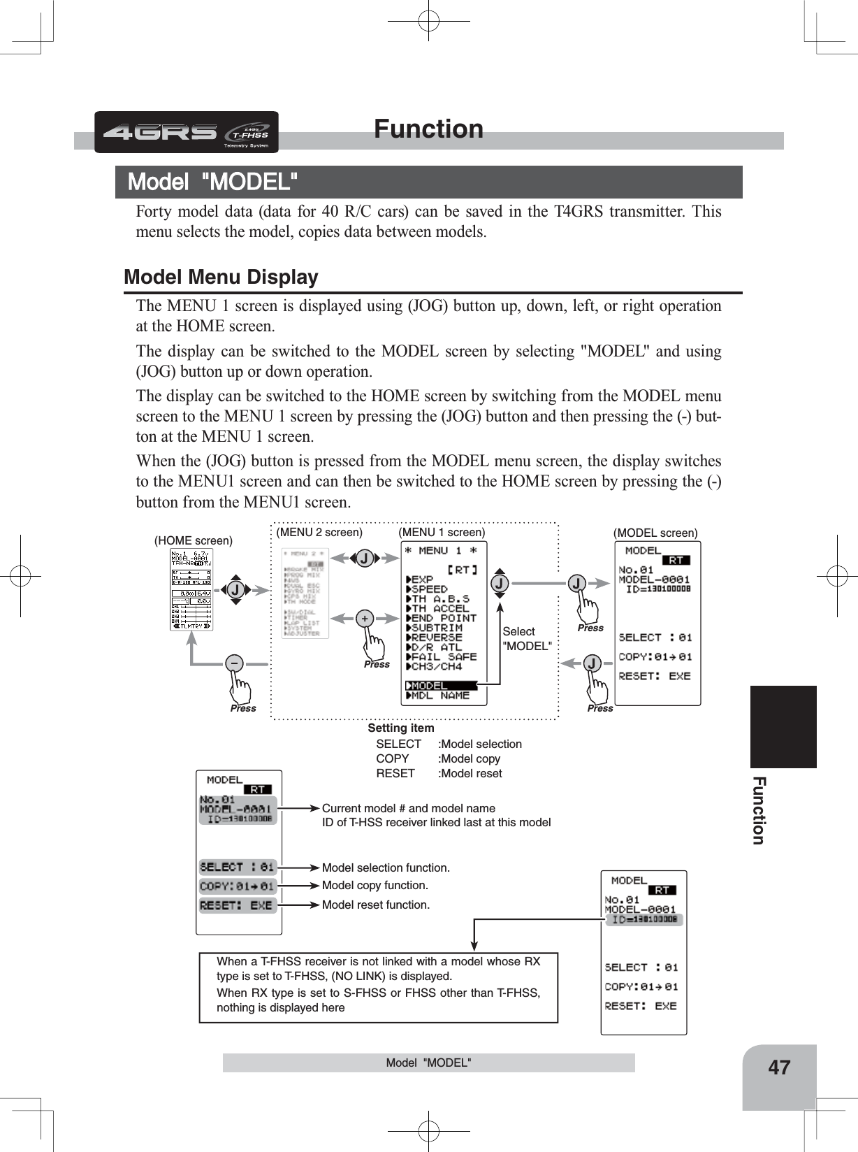
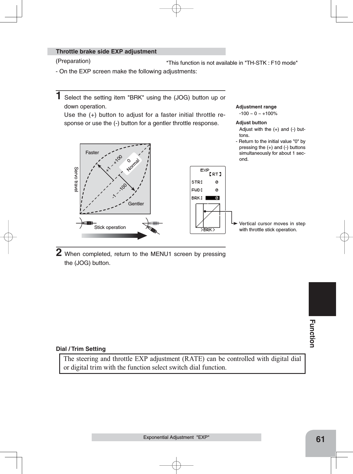
![Move the cursor to select mod-el # with the (JOG) button. Model #. 01~40Select model # with the (+) or (-) button.Modified model # and model name"COMPLETE!" is displayed.48FunctionModel Selection "SELECT"Forty model data (model data for 40 R/C cars) can be saved in the 4GRS transmitter and used when the relevant model data is called.Model "MODEL"When the model is changed, switch the transmitter "OFF" and then "ON" be-fore operation.- Display the MODEL screen.1(Selection of model select)Move the cursor to "SELECT" using the (JOG) button up or down operation.Using the model select function2(Model #. selection)Select the model number with the (+) or (-) button. "01" ~ "40" are displayed.3(Model select execution)Press the (JOG) button continuously for 1 second. A beeping sound is generated and the model is selected.- Model change is complete when the model No. and model name on the screen change and "COMPLETE!" is displayed .4When completed, move the cursor to [RT] by the (JOG) button, and return to the MENU1 screen by pressing the (JOG) button.](https://usermanual.wiki/Futaba/T4GRS-24G.User-Manual-Part-2/User-Guide-2495375-Page-5.png)
![Model name is also copied."COMPLETE!" is displayed.Move the cursor to "COPY" with the (JOG) button.The copy destination model # with the (+) or (-) button.Model #. 01~4049FunctionModel "MODEL"Model Copy "COPY"The contents of the currently selected model data can be copied to another model.- Display the MODEL screen.1(Selection of model copy)Move the cursor to "COPY" using the (JOG) button up or down operation.Using the model copy function2(Model #. selection)Select the copy destination model number with the (+) or (-) button. "01" ~ "40" are dis-played.3(Model copy execution)Press the (JOG) button for about 1 second. A beeping sound is generated and the model is selected.-Copying is complete when "COMPLETE!" is displayed on the screen.4When completed, move the cursor to [RT] by the (JOG) button, and return to the MENU1 screen by pressing the (JOG) button.](https://usermanual.wiki/Futaba/T4GRS-24G.User-Manual-Part-2/User-Guide-2495375-Page-6.png)
![Move the cursor to "RESET" with the (JOG) button."COMPLETE!" is displayed.The set RX type and T-FHSS receiver ID remain even if the model is reset. The same receiver can be used as is without re-linking50FunctionModel "MODEL"Using the model reset functionModel Reset "RESET"This function resets and initializes the contents of the currently selected model data.However, the adjuster function (ADJUSTER), system setting (SYSTEM), and type of receiver mode (TYPE) are not initialized.- Display the MODEL screen.1(Selection of model reset)Move the cursor to "RESET" using the (JOG) button up or down operation. 2(Model reset execution)Press the (JOG) button for about 1 second. A beeping sound is generated and the model is selected.-Resetting is complete when "COMPLETE!" is displayed on the screen.3When completed, move the cursor to [RT] by the (JOG) button, and return to the MENU1 screen by pressing the (JOG) button.](https://usermanual.wiki/Futaba/T4GRS-24G.User-Manual-Part-2/User-Guide-2495375-Page-7.png)
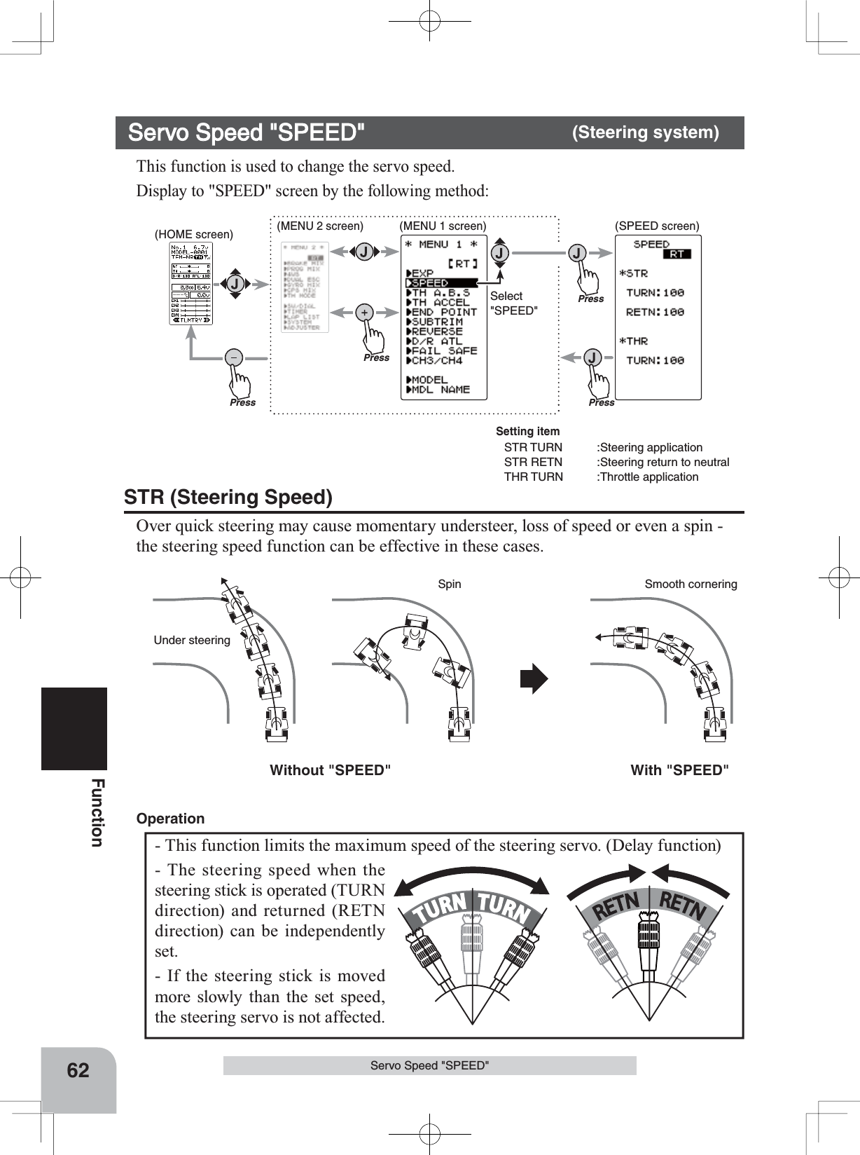
![Move the cursor to the char-acter you want to change by (+) or (-) button.Select the character by (JOG) button.Move the cursor to "RE-SET" by the (JOG) button up or down operation. [ RT ]Model nameUser nameCharacterPresscursor position [RT]PressPress(MDL NAME screen)PressSelect"MDL NAME"(HOME screen) (MENU 2 screen) (MENU 1 screen)When (JOG) button left or right operation is performed from both the left and right ends of the character list, the page (all 3 pages) is changed and the character set is selected.(KATAKANA of the 3rd page is displayed when "KANA" is set by the "SYSTEM" function "MENU".)51FunctionModel Name "MOE NAME"Setting the model name and user name1(Move the cursor to the character you want to change.)Select the model name character you want to set or change by moving the cursor using the (+) or (-) button. The selected character blinks.2(Selecting the character to be used)Select the character to be used from the character list at the lower section of the screen using the (JOG) button up, down, left, or right operation. The selected character blinks. After selecting the character to be used, press the (JOG) button. The character is entered and the model name or user name character row moves to the right. To clear the model or user name move the cursor to "RESET" using the (JOG) button up, down, left, or right operation, and press the button for about 1 second. A beeping sound is generated and the mod-el name is initialized to the factory setting.3When completed, move the cursor to [RT] using the (JOG) button, and return to the MENU1 screen by pressing the (JOG) button.Model Name "MDL NAME"This function allows you to assign a ten character name to each model memory anduser name. Display to "MDL NAME" screen by the following method:](https://usermanual.wiki/Futaba/T4GRS-24G.User-Manual-Part-2/User-Guide-2495375-Page-8.png)
![Setting itemSTR :Steering (1st channel)THR :Throttle (2nd channel)CH3 :3rd channelCH4 :4th channelMove the cursor to "STR, THR, CH3 and CH4" with the (JOG) button.PressPress(HOME screen) (MENU 2 screen) (REVERSE screen)Press(MENU 1 screen)PressSelect"REVERSE"52FunctionServo Reverse "REV"However, when the position set by trim or subtrim shifts from the center, the center becomes the opposite side. Servo Reverse "REVERSE" (All channel)This function reverses the direction of operation of the servos related to transmitter steering, throttle, and channel 3 /4 operation.(Preparation)- Select the channel to be set using the (JOG) button up or down operation.1(Servo reverse setting)Use the (+) or (-) button to reverse the servo operation direction.NOR/REV can also be set using (JOG) button left or right operation(Each channel can be set similarly.)Servo Reverse Function SettingSelect button- Select with the (+) or (-) but-tons.Display to "REVERSE" screen by the following method:2When completed, move the cursor to [RT] using the (JOG) button, and return to the MENU1 screen by pressing the (JOG) button.](https://usermanual.wiki/Futaba/T4GRS-24G.User-Manual-Part-2/User-Guide-2495375-Page-9.png)
![90°Use to adjust the neutral position Move the cursor to "STR, THR, CH3 and CH4" with the (JOG) button.Setting itemSTR :Steering (1st channel)THR :Throttle (2nd channel)CH3 :3rd channelCH4 :4th channelSubtrimPressPress(HOME screen) (MENU 2 screen) (SUBTRIM screen)Press(MENU 1 screen)PressSelect"SUBTRIM "Steering and throttle center trimWhen assigning DT1, DT2, or other digital trim-ming to another function, make adjustments at this screen.53FunctionSubtrim "SUBTR"Use this function to adjust the neutral position of the steering, throttle, channel 3 and channel 4 servos.(Preparation)- Set the steering and throttle digital trims to the neutral "0" posi-tion. Set CH3 and CH4 to the center "0" position. 1(Subtrim adjustment)Use the (+) or (-) button to adjust the center.(Each channel can be set similarly.)Subtrim adjustment*Subtrim adjusts the entire range of the servo in the set direction.Subtrim "SUBTRIM" (All channel)Adjust button- Adjust with the (+) and (-) but-tons.- Return to the initial value "0" by pressing the (+) and (-) buttons simultaneously for about 1 second.SubtrimST :L100~R100TH :B100~F100CH3 :-100~+100CH4 :-100~+100Initial value : 0Display to "REVERSE" screen by the following method:2When completed, move the cursor to [RT] by the (JOG) but-ton, and return to the MENU1 screen by pressing the (JOG) button.](https://usermanual.wiki/Futaba/T4GRS-24G.User-Manual-Part-2/User-Guide-2495375-Page-10.png)
![PressPressPressSelect"FAIL SAFE"Press(HOME screen) (MENU 2 screen) (FAIL SAFE screen)(MENU 1 screen)cursor position [RT]Setting itemMODE :F/S mode selectionPOSI :F/S positon setB-FS :B-FS set (throttle only)VOLT :B-FS voltage set (throttle only)57FunctionFail Safe Function "FAIL SAFE"Fail Safe Function "FAIL SAFE" (All channel)Fail Safe Mode (F/S)This function moves each servo to a preset position when the receiver does not receive a clear signal from the transmitter.-When the condition set at "FHSS" is Rx type, fail safe (F/S) can be set only for throttle (TH). Other channels are set to the normal mode.-The fail safe data is transferred from the transmitter to the receiver 10 seconds after the transmitter power is turned on. The GDWDLVWUDQVIHUUHGHYHU\VHFRQGVDIWHUWKDW%HFDUHIXOEHFDXVHQRUPDOO\WKHWUDQVPLWWHUSRZHULVWXUQHGRQ¿UVWDQGWKHUH-ceiver power is turned on next and the data is transferred for approximately 10 seconds after the receiver power is turned on.-For gasoline engine cars, for safety we recommend that this fail safe function be used to set the throttle channel in the direc-tion in which the brakes are applied.Hold mode (HOLD)This function holds the servo/s at the position they were in immediately before recep-tion was lost. This applies to the T-FHSS type (R304SB...,etc.) and the S-FHSS type (R2104GF...,etc.) receivers only. When the receiver used is an R603GF/2004GF or other FHSS type, this function is not available. Off mode (OFF)In this model the receiver stops outputting a signal to the servos if the transmitter signal is lost. The servos become effectively unpowered.The F/S, HOLD, and OFF modes are automatically reset when signals from the trans-mitter can be received again.Battery fail safe function (BFS)If the receiver battery voltage drops below a certain value when this function is enabled, the throttle servo moves to the position set by fail safe function. When the battery volt-age recovers, the battery fail safe function is automatically reset.-This function cannot be used when the throttle (TH) is not set to fail safe (F/S).-This function is for the T-FHSS type (R304SB...,etc.) and the S-FHSS type (R2104GF...,etc.) receiver only. It cannot be used with the R603GF and R2004FG and other FHSS type.Display to "FAIL SAFE" screen by the following method:](https://usermanual.wiki/Futaba/T4GRS-24G.User-Manual-Part-2/User-Guide-2495375-Page-14.png)
![FAIL SAFE screenBattery fail safe functionOFF, ACTInitial value: OFFB-F/S Voltage3.8, 4.0, 4.2, 4.4, 4.6, 4.8, 5.0, 5.3, 5.6, 5.9, 6.2, 6.5, 6.8, 7.1, 7.4(V)Initial value 3.8vExample:NiMH /NiCd 4cell---3.8VNiMH /NiCd 6cell---4.4VLiFe 2cell---4.8VLiPo 2cell---5.6V58FunctionFail Safe Function "FAIL SAFE"(Preparation)- Select the channels "MODE" to be set using the (JOG) button up, down, left, or right operation. 1(Mode selection)Select the mode by (+) or (-) button.(Each channel can be individually set.)2When completed, move the cursor to [RT] us-ing the (JOG) button, and return to the MENU1 screen by pressing the (JOG) button. When setting fail safe, set the servo position by the following method.Fail safe mode selection(Preparation)- Select the setting item using the (JOG) button. For Battery F/S function ON/OF, select "OFF" or "ACT" of "B-FS". For voltage setting, select RX**v. (The T-FHSS system only. )The S-FHSS system is fixed at 3.8v.1(Battery fail safe function ACT/OFF)BATT-F/S function ACT/OFF and voltage set-ting which activates the B-F/S function can be switched by (+) or (-) button.Battery fail safe function ON/OFF (T-FHSS/ S-FHSS)1(Servo position setup)When the fail safe function operates, select the setting item "POSI" using the (JOG) button. The steering stick, the throt-tle stick or 3rd, 4th channel dial should be positioned as re-quired in the event that the failsafe activates. When the (JOG) button is pressed for about 1 second, the servo position is displayed and you can confirm that the function was set.(Each channel can be set similarly.)2When completed, move the cursor to [RT] using the (JOG) but-ton, and return to the MENU1 screen by pressing the (JOG) button.Fail safe function setupF/S position setup button- The (JOG) buttons is pressed for about 1 second.F/S mode selection- Select with the (+) or (-) but-tons.F/S modeOFF, HOLD, F/S2When completed, move the cursor to [RT] using the (JOG) but-ton, and return to the MENU1 screen by pressing the (JOG) button.](https://usermanual.wiki/Futaba/T4GRS-24G.User-Manual-Part-2/User-Guide-2495375-Page-15.png)