Contents
- 1. User Manual Part 1
- 2. User Manual Part 2
- 3. User Manual Part 3
User Manual Part 2
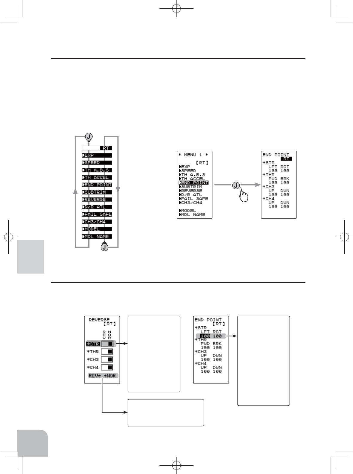
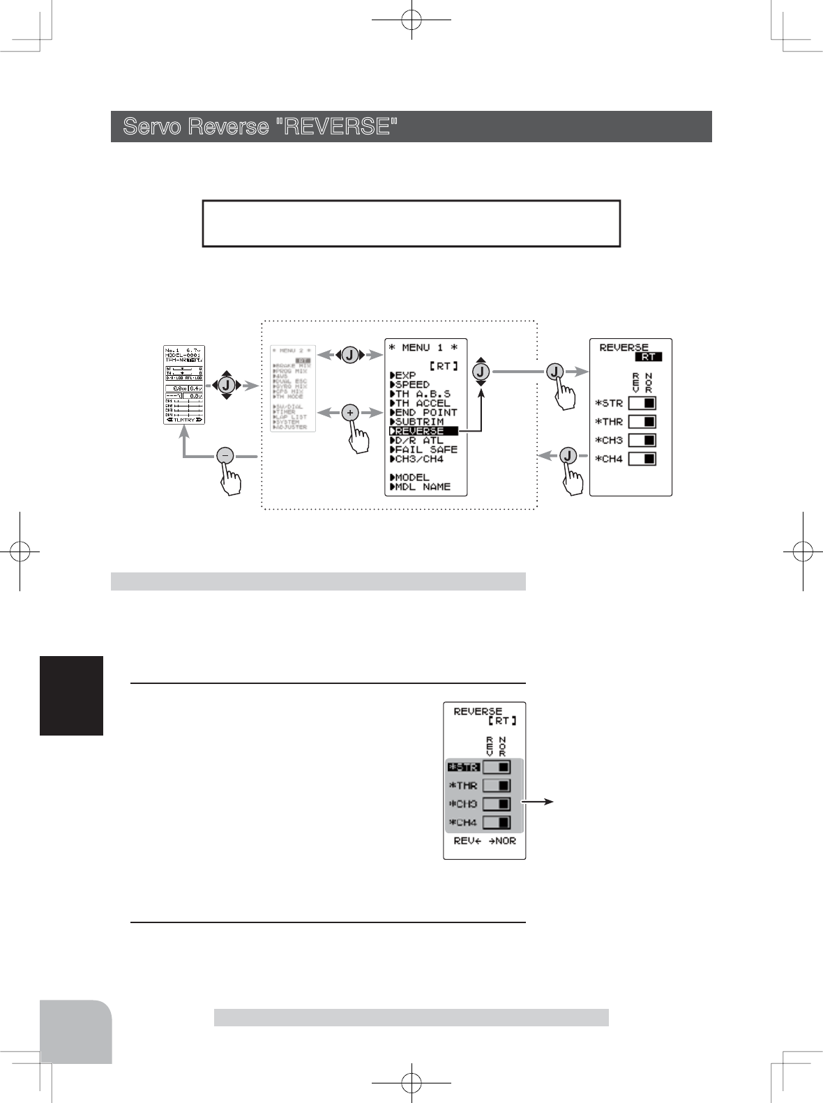
Example:
Select the chan-
nel to be changed
at the REVERSE
screen by (JOG)
button up or down
operation, and set
the servo direction
by selecting "NOR"
or "REV" with the
(+) button or (-) but-
ton.
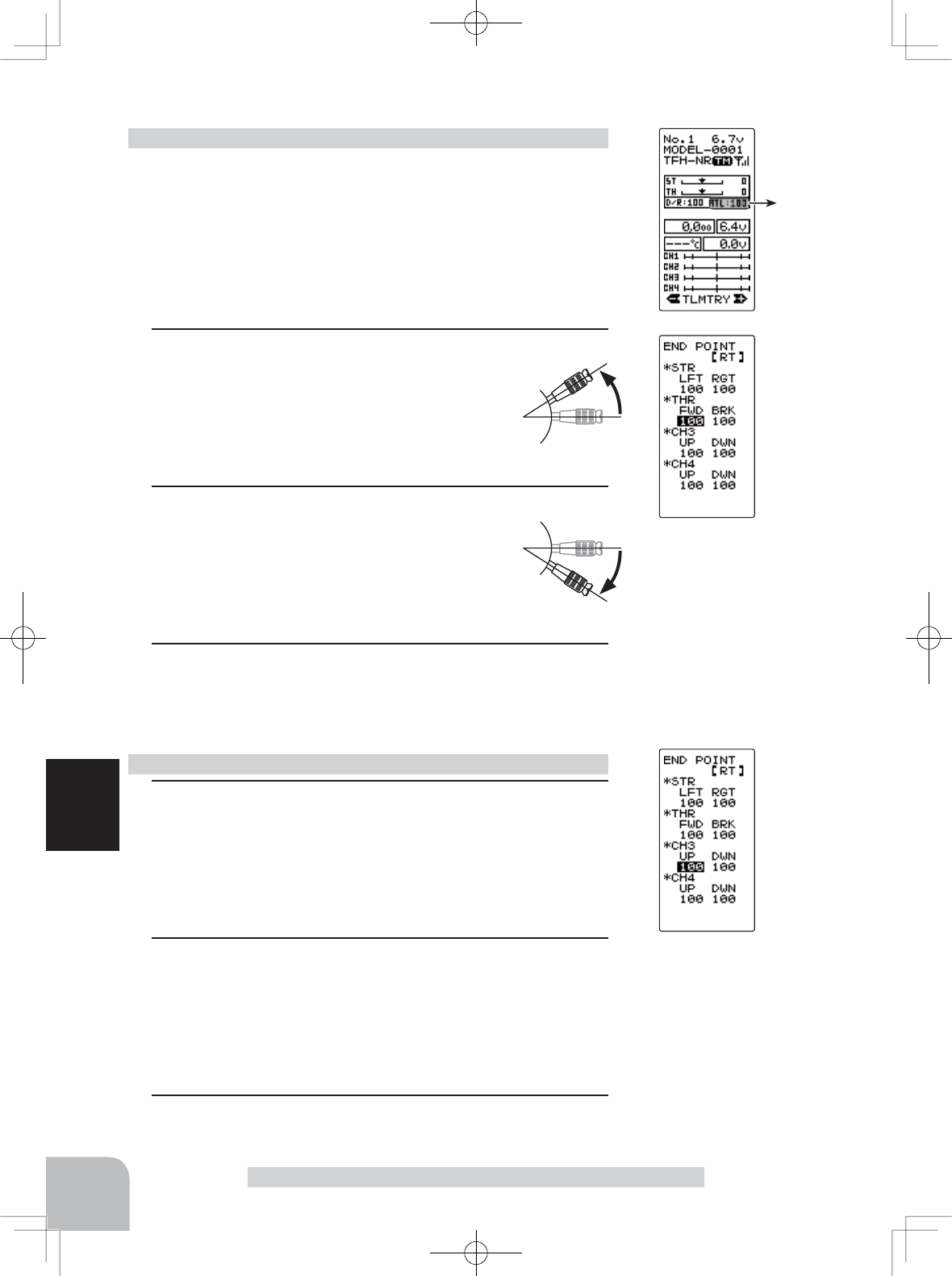
Example:
When changing the
left side travel of
the steering servo
at the END POINT
screen, select LFT
of the STR setting
item by (JOG) but-
ton up, down, left,
or right operation,
and set the steering
servo counterclock-
wise travel with the
(+) or (-) button.
On the MENU1 screen, move the
cursor to "END POINT"
(END POINT screen)
Pres
s
(JOG)button down operation
(JOG)button up operation
Move the cursor
When this is displayed, the
setting can also be changed
by (JOG) button left or right
operation.
44
Function Map
Value Of Each Function And Changing The Set Value
Values, settings, and other data on all the function setting screens are changed with the (+)
and (-) buttons.
Selecting Items On The Menu Screen
The item indicated by the highlighted cursor on the screen is selected.
The cursor is moved using the (JOG) button in up or down movements. The cursor
PRYHPHQW¿JXUHVKRZQEHORZLVDQH[DPSOHRIWKH0(18VFUHHQ+RZHYHUPRYH-
ment of the cursor is the same in all of the screens.
For instance, if the (JOG) button is pressed when the cursor is at the end point (EPA) on
WKH0(18VFUHHQWKHHQGSRLQW(1'32,17IXQFWLRQVHWWLQJVFUHHQDSSHDUV
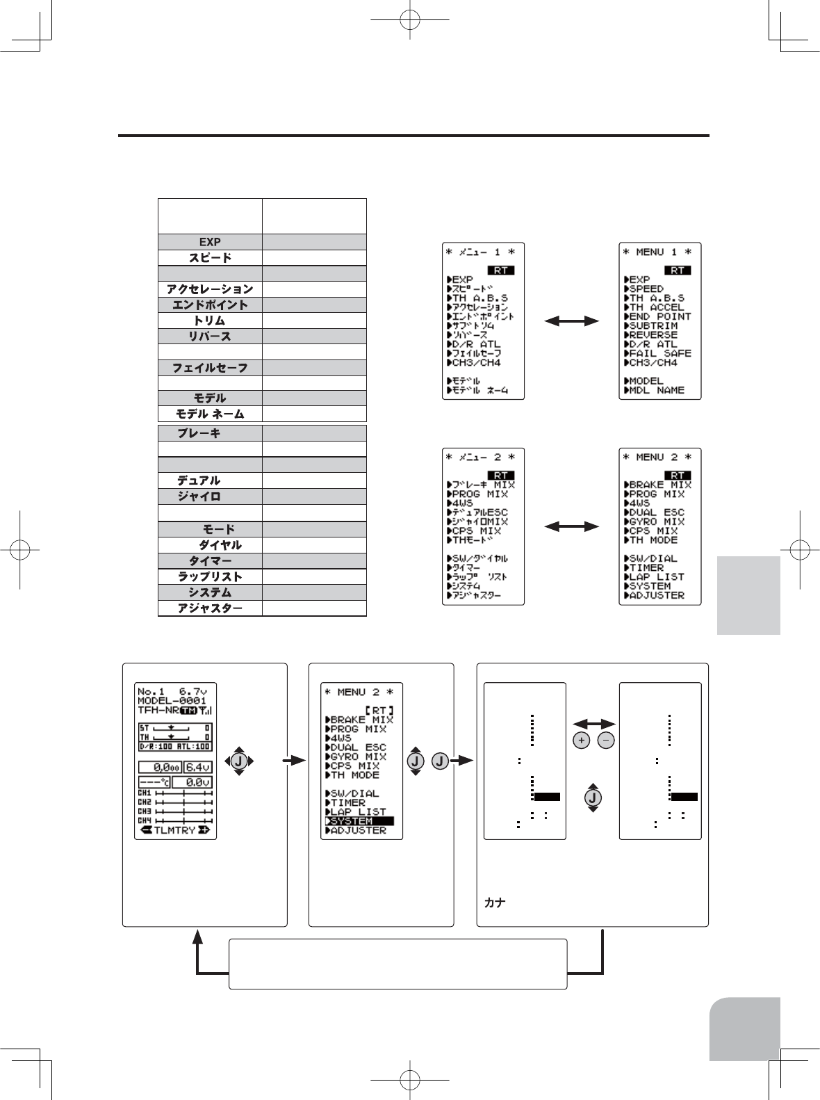
"KATAKANA"
characters
Alphabetic
characters
EXP
SPEED
TH A.B.S
TH A.B.S
TH ACCEL
END POINT
TRIM
REVERSE
D/R ATL
D/R ATL
FAIL SFE
CH3 /CH4
CH3 /CH4
MODEL
MDL NAME
MIX
BRAKE
MIX
PROG MIX
PROG
MIX
4WS
4WS
ESC
DUAL ESC
MIX
GYRO
MIX
CPS
MIX
CPS
MIX
TH
TH MODE
SW/
SW/DIAL
TIMER
LAP LIST
SYSTEM
ADJUSTER (MENU 2 screen)
(MENU 1 screen)
(SYSTEM screen)
CONTRA
LHT-TM
BK-LHT
SYSTEM
[ RT ]
LHT-PW
BATT DRY4
OPE-TM
BUZZER
MENU
TH-STK
DISP
0
ALL
10s
15
65
OFF
TLMTR
5 5
崓崲
CONTRA
LHT-TM
BK-LHT
SYSTEM
[ RT ]
LHT-PW
BATT DRY4
OPE-TM
BUZZER
MENU
TH-STK
DISP
0
ALL
10s
15
65
OFF
TLMTR
5 5
ENG
(HOME screen)
Call the MENU2 screen from the
HOME screen by the (JOG) but-
ton up, down, left or right
opera-
tion and press the (+) button.
On the MENU2 screen, move
the cursor to "SYSTEM" by
the
(JOG) button up or down op-
eration and press the button.
(MENU 2 screen)
45
Function Map
Basic Menu Japanese Katakana Character Display
On the system menu, the basic menu screen shown below can be displayed in Japanese
katakana characters.
On the SYSTEM screen, select MENU by
pressing the (JOG) button and select "ENG" or
"" by pressing the (+) or (-) button.
Changing the character
After changing the setting, return to the MENU2 screen by
pressing the (JOG) button or return to the HOME screen by se-
lecting [RT] and pressing the (JOG) button.
46
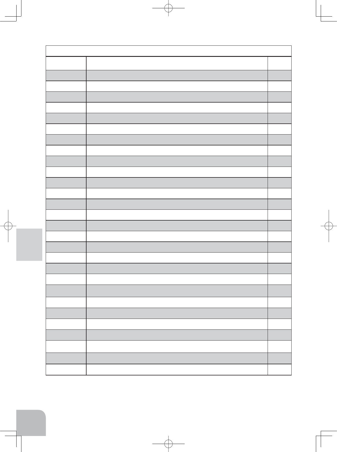
Function Map
Function
Abbreviation Description Of Function Page No
RX MODE
5HFHLYHUW\SHVHOHFWLRQOLQNLQJZLWKWHOHPHWU\W\SH7)+66V\VWHPUHFHLYHU P-37
MODEL
0RGHOPHPRU\VHOHFW0RGHOPHPRU\FRS\0RGHOPHPRU\UHVHW P-47
MDL NAME
0RGHOPHPRU\QDPHVHWPRGLI\XVHUQDPHVHWPRGLI\ P-50
REVERSE
Servo reversing P-52
SUBTRIM
6HUYRFHQWHUSRVLWLRQ¿QHDGMXVWPHQW P-53
END POINT
(QGSRLQWDGMXVWPHQW P-54
FAIL SAFE
Fail safe, battery fail safe P-57
EXP
6WHHULQJFXUYHDGMXVWPHQW7KURWWOHFXUYHDGMXVWPHQW P-59
SPEED
Steering servo delay/ Throttle servo delay P-62
TH ACCEL
Reduces the "lag time" of the throttle from the neutral position. P-65
TH A.B.S Pulsing brake
P-67
CH3/CH4
Channel 3&4 servos operation position set/check P-71
D/R ATL
6WHHULQJDQJOHDGMXVWPHQWZKLOHUXQQLQJ%UDNHVLGHDGMXVWPHQW P-72
SW/DIAL
Selection of functions operated by switch, digital dial and digital trim P-73
BRAKE MIX
)URQWDQGUHDULQGHSHQGHQWEUDNHFRQWUROIRU*3FDUHWF P-76
PROG MIX
3URJUDPPDEOHPL[LQJEHWZHHQVSHFL¿FFKDQQHOV P-78
4WS MIX
:6PL[LQJ P-80
DUAL ESC
)URQWDQGUHDU(6&VPL[LQJ P-82
GYRO ESC
7KHVHQVLWLYLW\RI)XWDEDFDUUDWHJ\URVFDQEHDGMXVWHG P-84
CPS ESC
7KH&36RI)XWDED/('FRQWUROOHUFDQEHDGMXVWHG P-86
TH MODE
Throttle servo forward side and brake side operation rate setting/ Neutral brake/ Idle
up at engine start/ engine cut off by switch P-88
MC LINK
0&&&&5&5&5&5/LQNVRIWZDUHVHWWLQJIXQFWLRQ P-92
MDL TRANS
Data copy from T4GRS to another T4GRS P-100
TIMER
8SGRZQRUODSWLPHU P-102
LAP LIST
/DSWLPHUGDWDODSWLPHWRWDOWLPHFKHFN P-108
SYSTEM
/&'FRQWUDVWEDFNOLJKW%DWWHU\W\SHEX]]HUSRZHUOHIW³21´DODUP%DVLFPHQXFKDUDFWHU
GLVSOD\7KURWWOHVWLFNDGMXVWPHQW+20(VFUHHQGLVSOD\PRGH
P-109
ADJUSTR
Steering stick and throttle stick correction P-113
TELEMETRY
Displays the status during operation, of each sensor unit and records the status in a data log. P-115
Function List
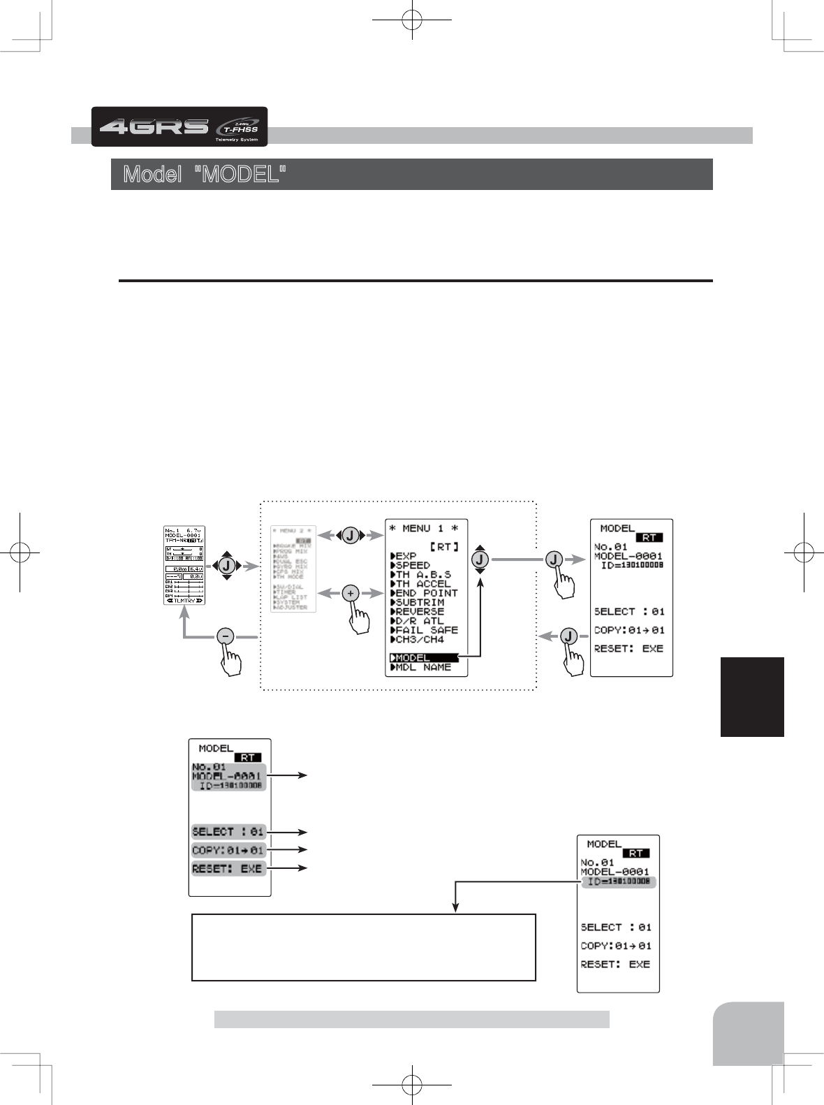
Current model # and model name
ID of T-HSS receiver linked last at this model
Model copy function.
Model reset function.
Model selection function.
When a T-FHSS receiver is not linked with a model whose RX
type is set to T-FHSS, (NO LINK) is displayed.
When RX type is set to S-FHSS or FHSS other than T-FHSS,
nothing is displayed here
Pres
s
Pres
s
(HOME screen) (MENU 2 screen) (MODEL screen)
Pres
s
(MENU 1 screen)
Pres
s
Select
"MODEL"
Setting item
SELECT :Model selection
COPY :Model copy
RESET :Model reset
47
Function
Function
Model "MODEL"
Model "MODEL"
Forty model data (data for 40 R/C cars) can be saved in the T4GRS transmitter. This
menu selects the model, copies data between models.
Model Menu Display
The MENU 1 screen is displayed using (JOG) button up, down, left, or right operation
at the HOME screen.
The display can be switched to the MODEL screen by selecting "MODEL" and using
(JOG) button up or down operation.
The display can be switched to the HOME screen by switching from the MODEL menu
screen to the MENU 1 screen by pressing the (JOG) button and then pressing the (-) but-
ton at the MENU 1 screen.
When the (JOG) button is pressed from the MODEL menu screen, the display switches
to the MENU1 screen and can then be switched to the HOME screen by pressing the (-)
button from the MENU1 screen.
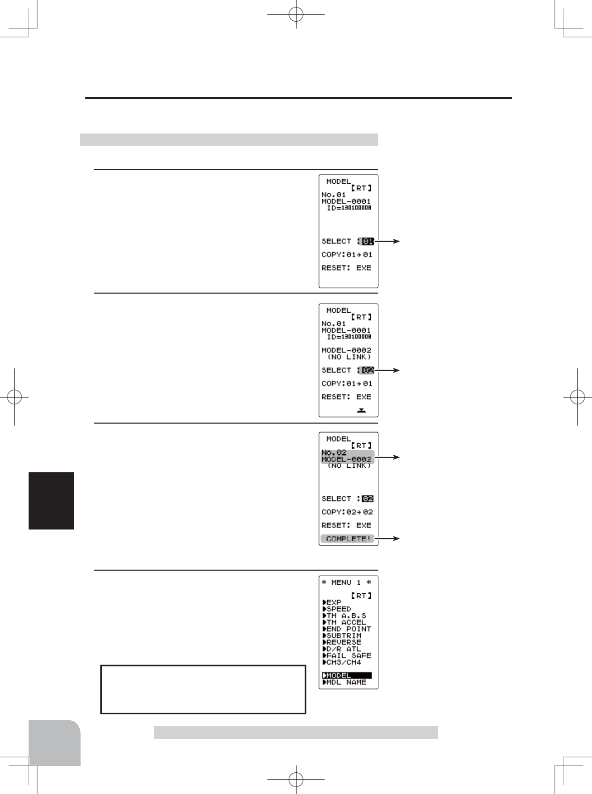
Move the cursor to select mod-
el # with the (JOG) button.
Model #.
01~40
Select model # with the (+) or (-)
button.
Modified model # and model
name
"COMPLETE!" is displayed.
48
Function
Model Selection "SELECT"
Forty model data (model data for 40 R/C cars) can be saved in the 4GRS transmitter and
used when the relevant model data is called.
Model "MODEL"
When the model is changed, switch the
transmitter "OFF" and then "ON" be-
fore operation.
- Display the MODEL screen.
1(Selection of model select)
Move the cursor to "SELECT" using the (JOG)
button up or down operation.
Using the model select function
2(Model #. selection)
Select the model number with the (+) or (-)
button. "01" ~ "40" are displayed.
3(Model select execution)
Press the (JOG) button continuously for 1
second. A beeping sound is generated and
the model is selected.
- Model change is complete when the model No. and model
name on the screen change and "COMPLETE!" is displayed .
4When completed, move the cursor to [RT] by
the (JOG) button, and return to the MENU1
screen by pressing the (JOG) button.
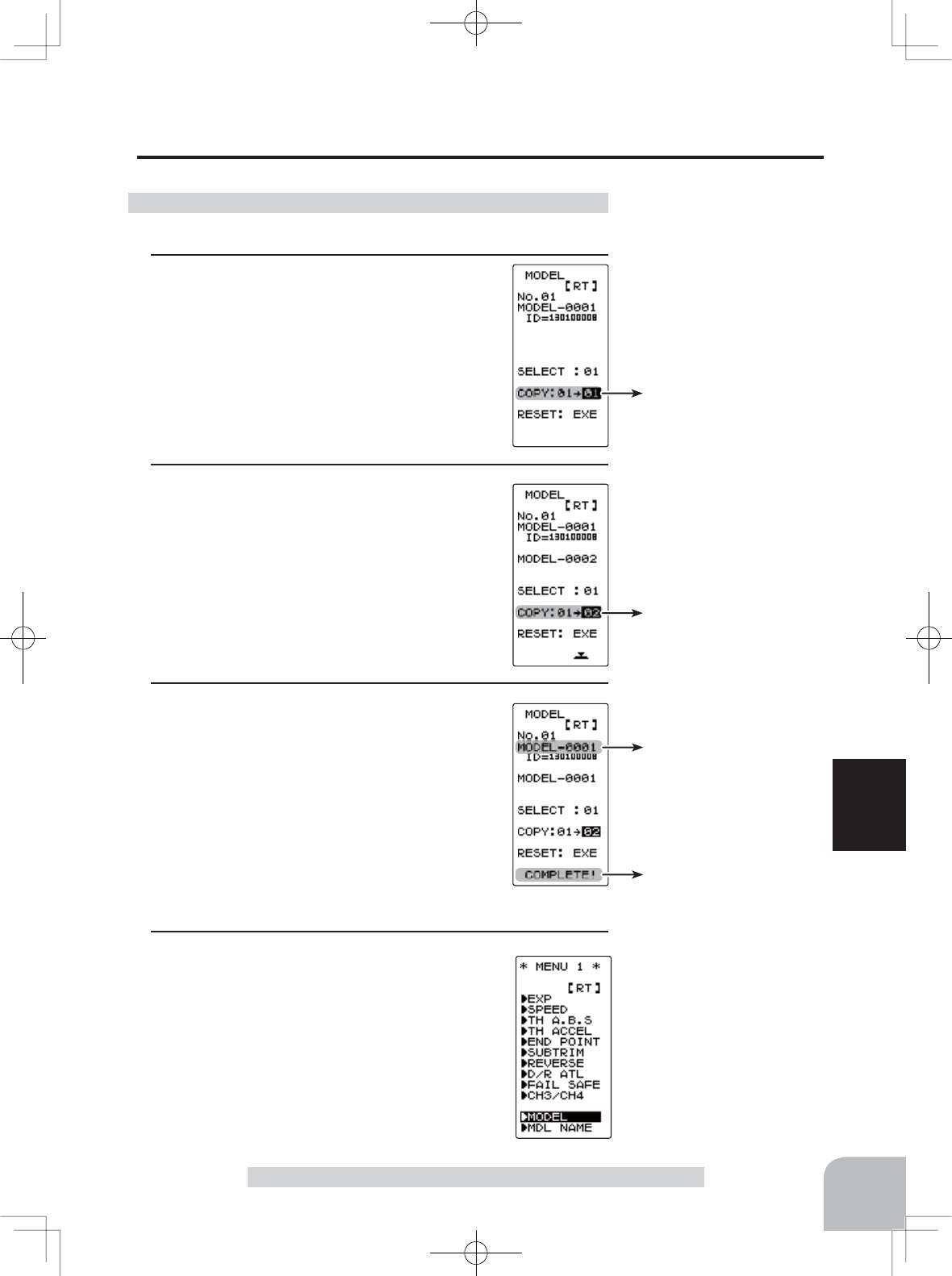
Model name is also copied.
"COMPLETE!" is displayed.
Move the cursor to "COPY"
with the (JOG) button.
The copy destination model #
with the (+) or (-) button.
Model #.
01~40
49
Function
Model "MODEL"
Model Copy "COPY"
The contents of the currently selected model data can be copied to another model.
- Display the MODEL screen.
1(Selection of model copy)
Move the cursor to "COPY" using the (JOG)
button up or down operation.
Using the model copy function
2(Model #. selection)
Select the copy destination model number
with the (+) or (-) button. "01" ~ "40" are dis-
played.
3(Model copy execution)
Press the (JOG) button for about 1 second. A
beeping sound is generated and the model is
selected.
-Copying is complete when "COMPLETE!" is displayed on the screen.
4When completed, move the cursor to [RT] by
the (JOG) button, and return to the MENU1
screen by pressing the (JOG) button.
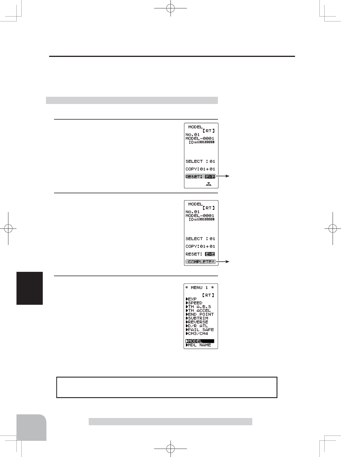
Move the cursor to "RESET"
with the (JOG) button.
"COMPLETE!" is displayed.
The set RX type and T-FHSS receiver ID remain even if the model is reset. The
same receiver can be used as is without re-linking
50
Function
Model "MODEL"
Using the model reset function
Model Reset "RESET"
This function resets and initializes the contents of the currently selected model data.
However, the adjuster function (ADJUSTER), system setting (SYSTEM), and type of
receiver mode (TYPE) are not initialized.
- Display the MODEL screen.
1(Selection of model reset)
Move the cursor to "RESET" using the
(JOG) button up or down operation.
2(Model reset execution)
Press the (JOG) button for about 1 second. A
beeping sound is generated and the model is
selected.
-Resetting is complete when "COMPLETE!" is displayed on
the screen.
3When completed, move the cursor to [RT] by
the (JOG) button, and return to the MENU1
screen by pressing the (JOG) button.
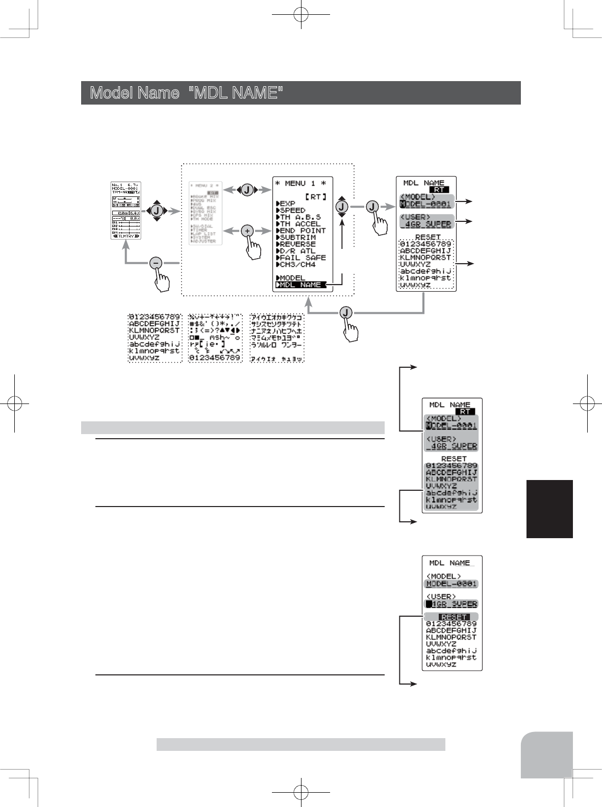
Move the cursor to the char-
acter you want to change by
(+) or (-) button.
Select the character by
(JOG) button.
Move the cursor to "RE-
SET" by the (JOG) button
up or down operation.
[ RT ]
Model name
User name
Character
Pres
s
cursor position [RT]
Pres
s
Pres
s
(MDL NAME screen)
Pres
s
Select
"MDL NAME"
(HOME screen) (MENU 2 screen) (MENU 1 screen)
When (JOG) button left or right operation is performed from both the left
and right ends of the character list, the page (all 3 pages) is changed
and the character set is selected.
(KATAKANA of the 3rd page is displayed when "KANA" is set by the
"SYSTEM" function "MENU".)
51
Function
Model Name "MOE NAME"
Setting the model name and user name
1(Move the cursor to the character you want to change.)
Select the model name character you want to set or change
by moving the cursor using the (+) or (-) button. The selected
character blinks.
2(Selecting the character to be used)
Select the character to be used from the character list at the
lower section of the screen using the (JOG) button up, down,
left, or right operation. The selected character blinks. After
selecting the character to be used, press the (JOG) button.
The character is entered and the model name or user name
character row moves to the right. To clear the model or user
name move the cursor to "RESET" using the (JOG) button
up, down, left, or right operation, and press the button for
about 1 second. A beeping sound is generated and the mod-
el name is initialized to the factory setting.
3When completed, move the cursor to [RT] using the (JOG)
button, and return to the MENU1 screen by pressing the
(JOG) button.
Model Name "MDL NAME"
This function allows you to assign a ten character name to each model memory and
user name.
Display to "MDL NAME" screen by the following method:
Setting item
STR :Steering (1st channel)
THR :Throttle (2nd channel)
CH3 :3rd channel
CH4 :4th channel
Move the cursor to "STR, THR,
CH3 and CH4" with the (JOG)
button.
Pres
s
Pres
s
(HOME screen) (MENU 2 screen) (REVERSE screen)
Pres
s
(MENU 1 screen)
Pres
s
Select
"REVERSE"
52
Function
Servo Reverse "REV"
However, when the position set by trim or subtrim shifts from
the center, the center becomes the opposite side.
Servo Reverse "REVERSE" (All channel)
This function reverses the direction of operation of the servos related to transmitter
steering, throttle, and channel 3 /4 operation.
(Preparation)
- Select the channel to be set using the (JOG) button up or
down operation.
1(Servo reverse setting)
Use the (+) or (-) button to reverse the servo
operation direction.
NOR/REV can also be set using (JOG) button
left or right operation
(Each channel can be set similarly.)
Servo Reverse Function Setting
Select button
- Select with the (+) or (-) but-
tons.
Display to "REVERSE" screen by the following method:
2When completed, move the cursor to [RT] using the (JOG)
button, and return to the MENU1 screen by pressing the
(JOG) button.
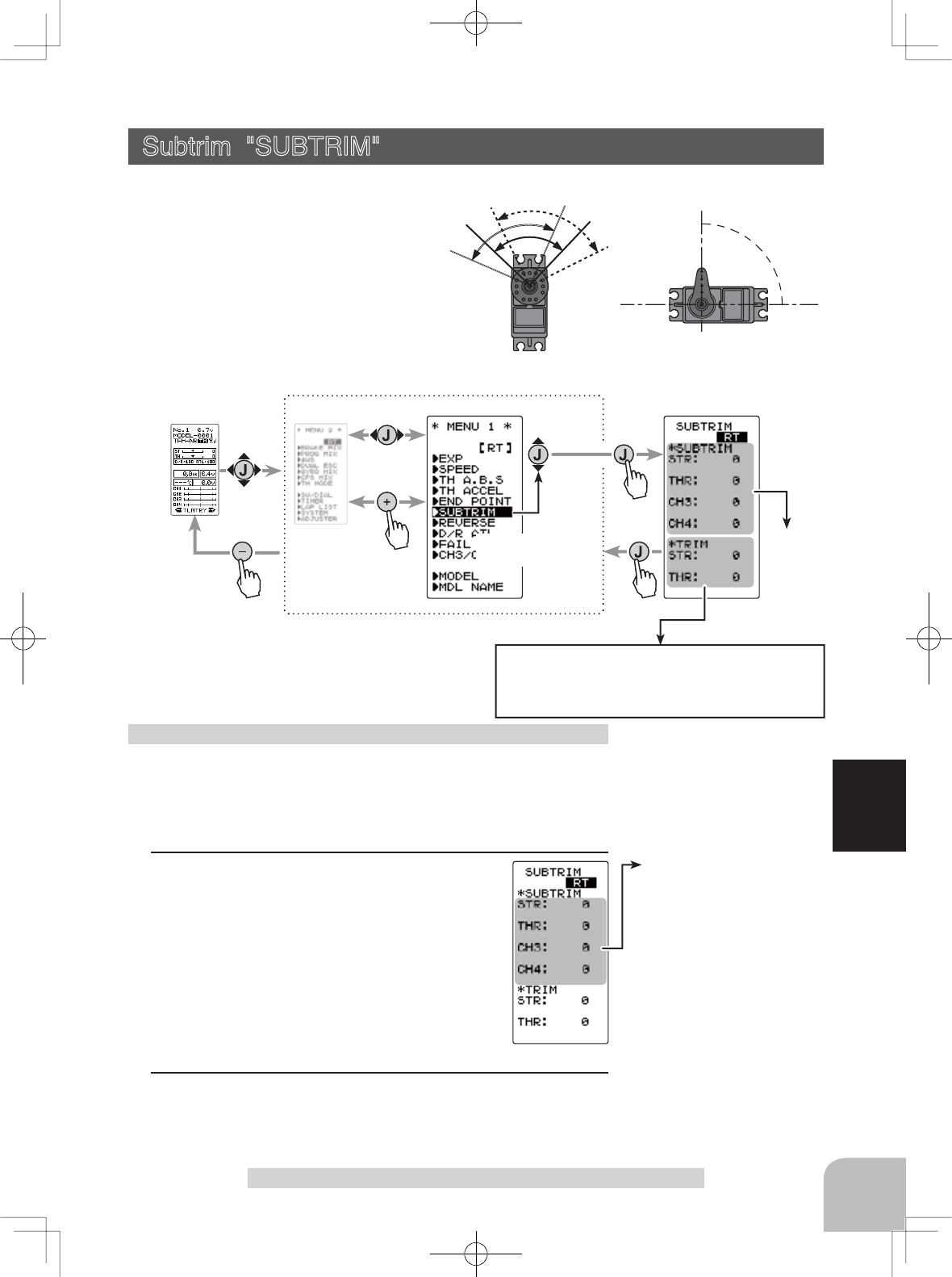
90°
Use to adjust the neutral position
Move the cursor to "STR, THR,
CH3 and CH4" with the (JOG)
button.
Setting item
STR :Steering (1st channel)
THR :Throttle (2nd channel)
CH3 :3rd channel
CH4 :4th channel
Subtrim
Pres
s
Pres
s
(HOME screen) (MENU 2 screen) (SUBTRIM screen)
Pres
s
(MENU 1 screen)
Pres
s
Select
"
SUBTRIM
"
Steering and throttle center trim
When assigning DT1, DT2, or other digital trim-
ming to another function, make adjustments at this
screen.
53
Function
Subtrim "SUBTR"
Use this function to adjust the neutral position of the steering, throttle, channel 3
and channel 4 servos.
(Preparation)
- Set the steering and throttle digital trims to the neutral "0" posi-
tion. Set CH3 and CH4 to the center "0" position.
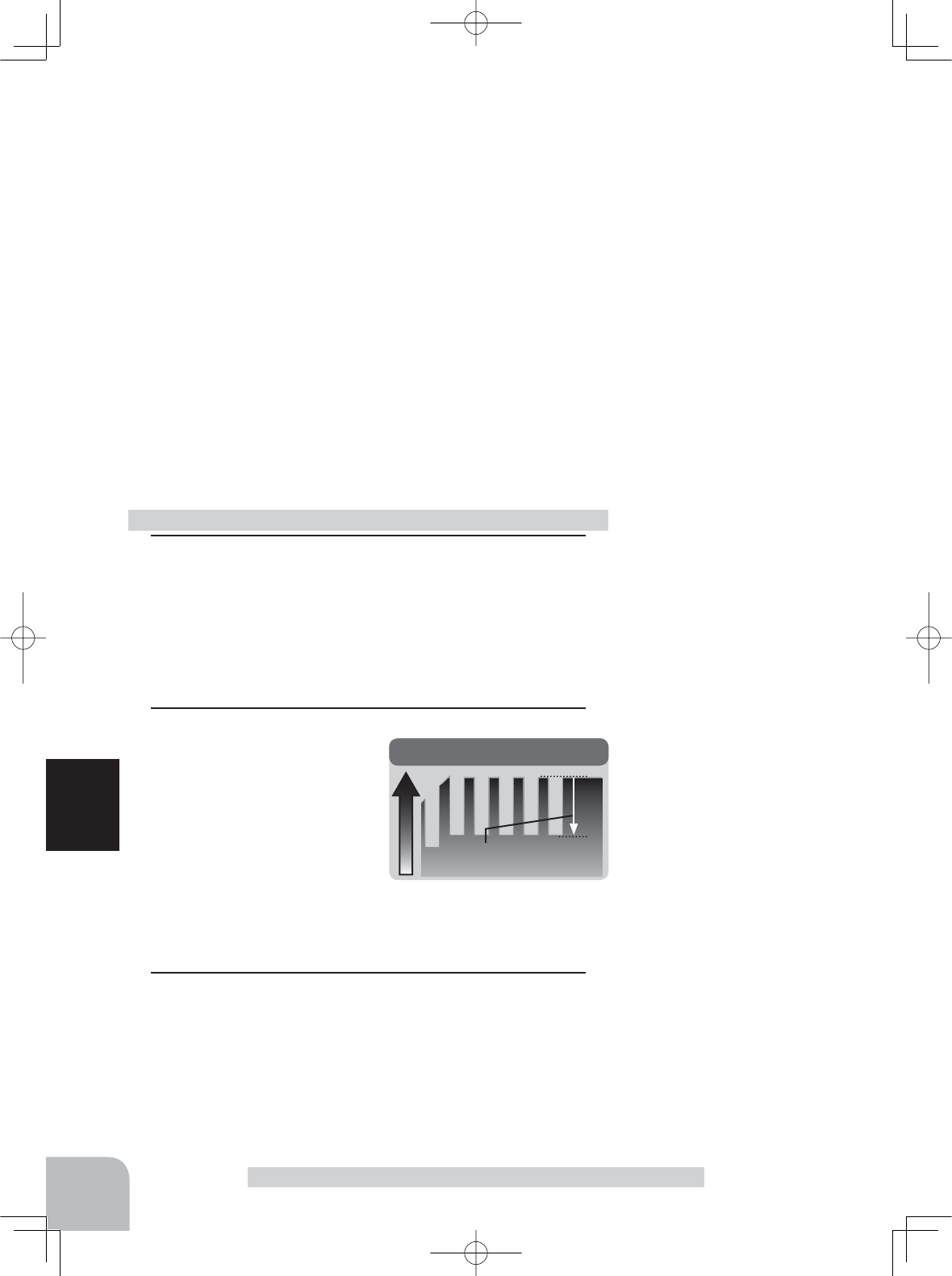
1(Subtrim adjustment)
Use the (+) or (-) button to adjust the center.
(Each channel can be set similarly.)
Subtrim adjustment
*Subtrim adjusts the entire range of
the servo in the set direction.
Subtrim "SUBTRIM" (All channel)
Adjust button
- Adjust with the (+) and (-) but-
tons.
- Return to the initial value "0"
by pressing the (+) and (-)
buttons simultaneously for
about 1 second.
Subtrim
ST :L100~R100
TH :B100~F100
CH3 :-100~+100
CH4 :-100~+100
Initial value : 0
Display to "REVERSE" screen by the following method:
2When completed, move the cursor to [RT] by the (JOG) but-
ton, and return to the MENU1 screen by pressing the (JOG)
button.
54
Function
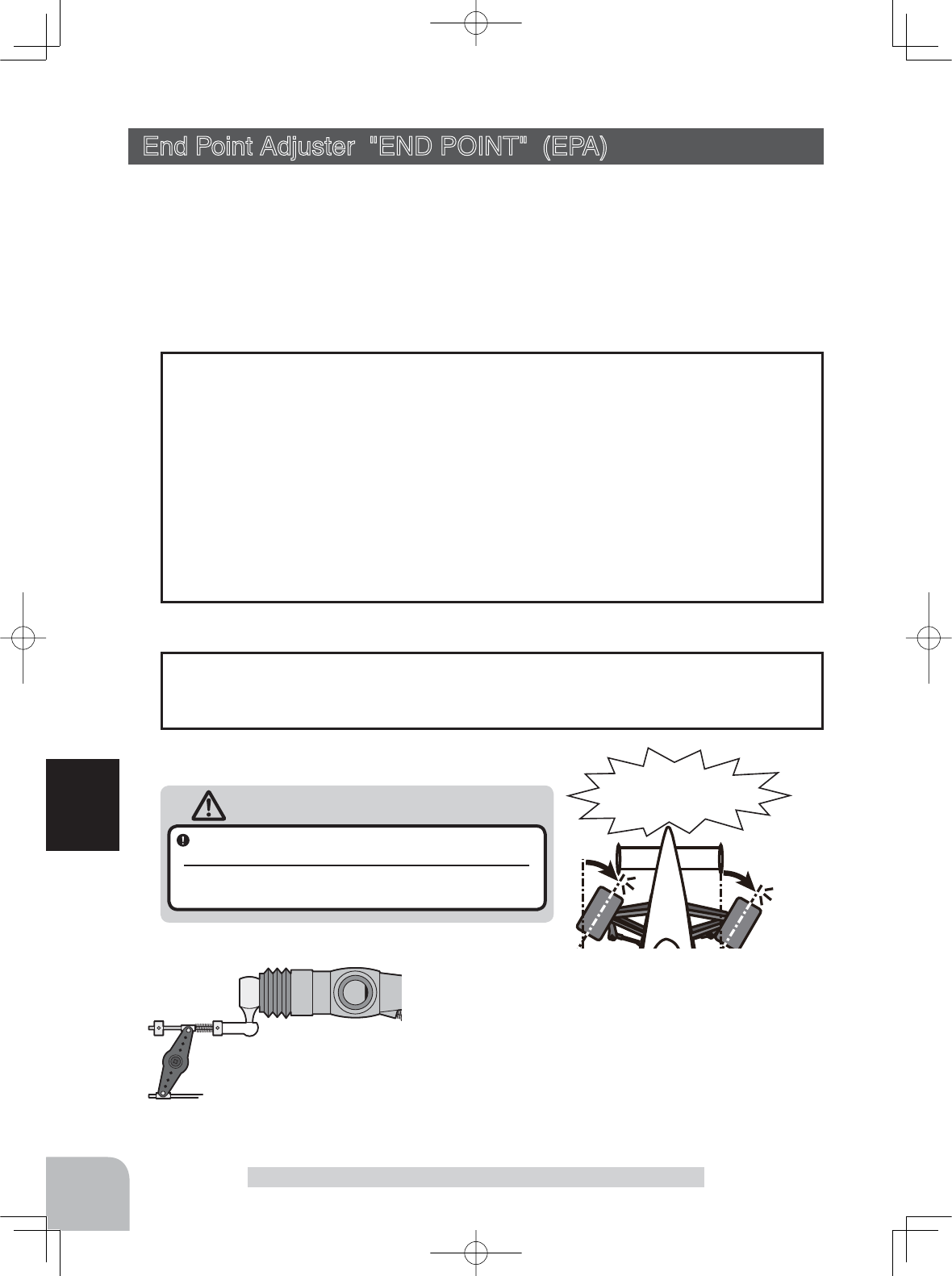
Warning
End Point Adjuster "END POINT" (EPA) (All channel)
Use this when performing left and right end point adjustments, throttle high side/
brake side operation amount adjustment, channel 3 and channel 4 servo up side/
down side operation amount adjustment during linkage.
- Correct the maximum steering angle for left and right steering angles when there
is a difference in the turning radius due to the characteristics, etc. of the vehicle.
The EPA function basically determines the maximum steering angle of each channel.
The functions shown below may have been adjusted or the operating range set by EPA
function may be exceeded. Check the linkage each time the following functions are
adjusted.
- Sub trim (all channels) .................................. P53
- Program mixing slave side (all channels) .....P78
- Idle up (throttle) ............................................ P89
- Throttle off, Engine cut (throttle).................. P91
- Throttle acceration (throttle)......................... P65
Maximum steering angle
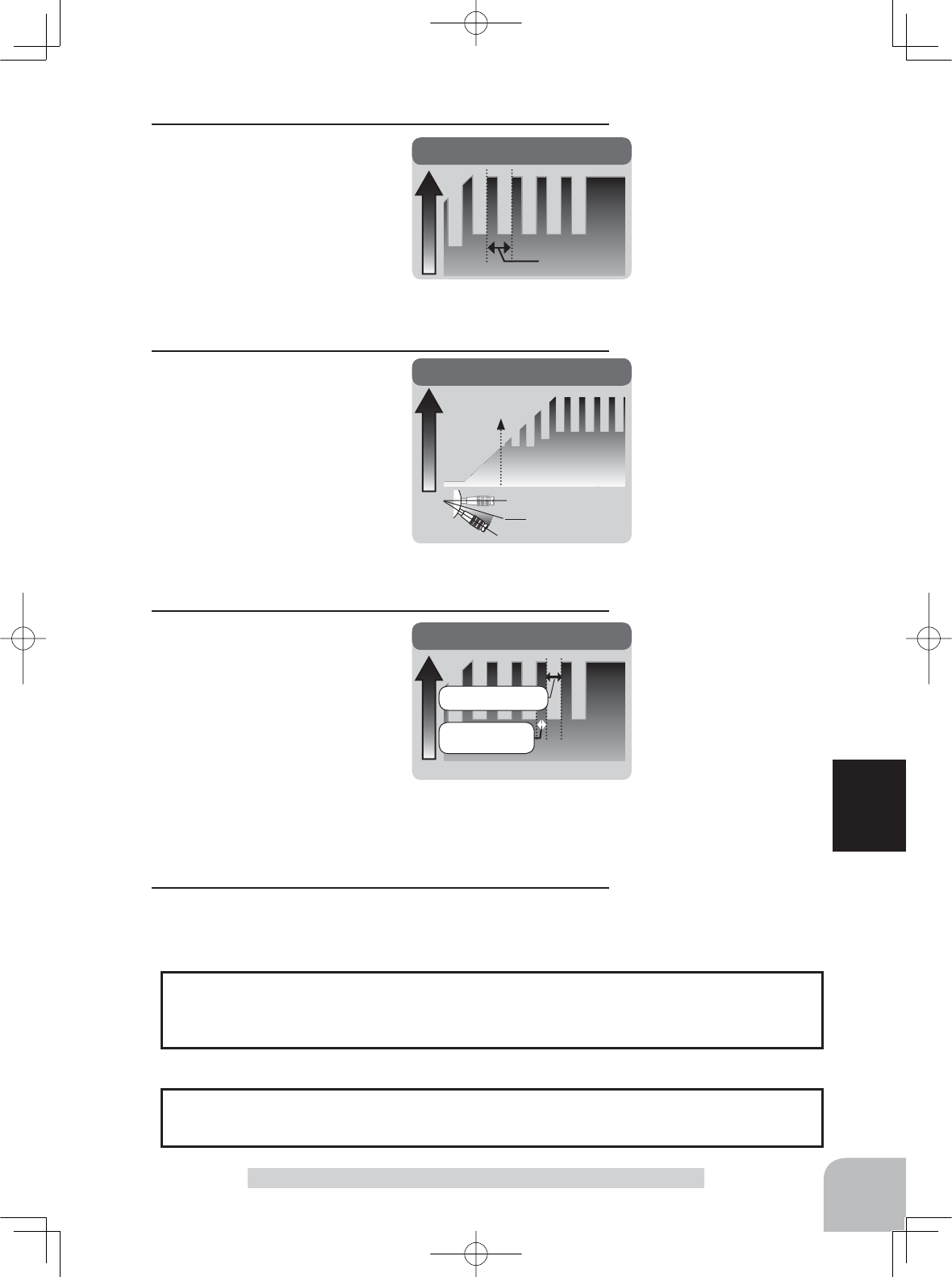
ATL trim allows adjustment of the brake side operation amount during operation.
Therefore, when the operating angle is adjusted with throttle EPA, ATL trim must also
be taken into account.
ATL trim
End Point Adjuster "END POINT"
Operate each servo over its full stroke and be sure
the linkage does not bind or is not loose.
The continuous application of excessive force to a servo may
cause damage and excessive battery drain.
Adjust the throttle servo so that excessive force is not applied when the engine carburetor is fully
open, fully closed, and the brakes are applied fully.
If the brakes overheat while running, their ability to function properly decreases. Before running,
adjust the suitable maximum servo travel so that excessive force is not applied even when the servo
travel is increased while running.
Adjust the steering servo so that excessive
force is not applied to the servo by the chas-
sis at maximum servo travel.
Decide the EPA value at the
contact point.
Caution!
A whining noise indicates that the
steering servo is improperly set.
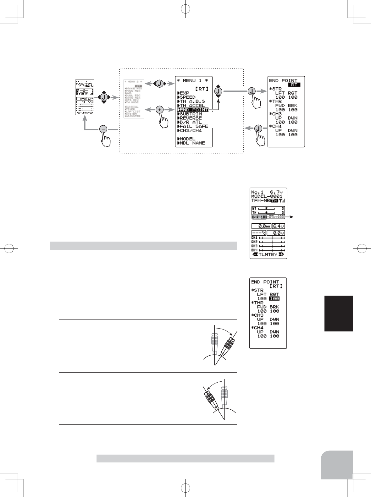
Setting item selection
(Steering and Throttle direction)
- The direction (STR LFT and STR RGT) linked with the steering stick is switched.
- The direction (THR FWD and THR BRK) linked with the throttle stick is switched.
Setting item (channel and direction)
STR LFT :Steering (left side)
STR RGT :Steering (right side)
THR FWD :Throttle (foward side)
THR BRK :Throttle (brake side)
CH3/CH4 UP :3rd or 4th channel (up side)
CH3/CH4 DWN :3rd or 4th channel (down side)
(HOME screen)
100
Pres
s
Pres
s
(HOME screen) (MENU 2 screen) (
END POINT
screen)
(MENU 1 screen)
Pres
s
Pres
s
Select
"END POINT"
55
Function
End Point Adjuster "END POINT"
(Preparation)
- Before setup of the steering end point adjustment (END
POINT), set the steering D/R lever (initial setup: DT3) to the
maximum steering angle position 100%.
- Select the setting item "RGT" using the (JOG) button up, down,
left, or right operation and make the following adjustments:
1Steering (left side) adjustment
Move the steering stick fully to the left and
use the (+) or (-) buttons to adjust the steer-
ing angle.
2Steering (right side) adjustment
Move the steering stick fully to the right and
use the (+) or (-) buttons to adjust the steer-
ing angle.
3When complete, return to the MENU1 screen by pressing
the (JOG) button.
Steering (END POINT) adjustment
Adjust button
Adjust with the (+) and (-)
buttons.
- Return to the initial value
"100" by pressing the (+) and
(-) buttons simultaneously for
about 1 second.
Steering EPA
STR LFT :0~120
STR RGT :0~120
Initial value :100
Display to "END POINT" screen by the following method:
(HOME screen)
100
*This function cannot be used with "TH-STK : F10".
56
Function
End Point Adjuster "END POINT"
(Preparation)
- Before setting the throttle end point adjustment (END POINT),
set the throttle ATL (initial setup: DT4) to the maximum throttle
angle position 100%.
- Select the setting item "FWD" by the (JOG) button up or down
operation and make the following adjustments:
1Throttle (full power) adjustment
Push the throttle stick forward to the full power
position and use the (+) or (-) buttons to ad-
just the throttle angle. However, when using an
FET amp, set to 100%.
2Throttle (brake side/reverse side) adjustment
Pull the throttle stick full back to brake/reverse
and use the (+) or (-) buttons to adjust the
throttle angle. However, when using an ESC,
set to 100%.
3When completed, return to the MENU1 screen by pressing
the (JOG) button.
Throttle (END POINT) adjustment
13rd/4th channel servo (up position) adjustment
Select the setting item "CH3 or CH4 UP" using the (JOG)
button up or down operation, and set the 3rd or 4th channel
dial fully to the up using (+ side) and use the (+) or (-) but-
tons to adjust the servo angle.
23rd/4th channel servo (down position) adjustment
Select the setting item "CH3 or CH4 DWN" using the (JOG)
button up or down operation, and set the 3rd or 4th channel
dial fully to the up position (- side) and use the (+) or (-) but-
tons to adjust the servo angle.
3When completed, return to the MENU1 screen by pressing
the (JOG) button.
3rd & 4th channel servo (END POINT) adjustment
Adjust button
- Use the (+) and (-) buttons to
make adjustments.
- Return to the initial value
"100" by pressing the (+) and
(-) buttons simultaneously for
about 1 second.
Throttle EPA
THR FWD :0~120
THR BRK :0~120
Initial value :100
Adjust button
Adjust with the (+) and (-) but-
tons.
- Return to the initial value "100"
by pressing the (+) and (-) but-
tons simultaneously for about 1
second.
3rd & 4th channel EPA
CH3/CH4 UP :0~120
CH3/CH4 DWN :0~120
Initial value :100
Pres
s
Pres
s
Pres
s
Select
"FAIL SAFE"
Pres
s
(HOME screen) (MENU 2 screen) (
FAIL SAFE
screen)(MENU 1 screen)
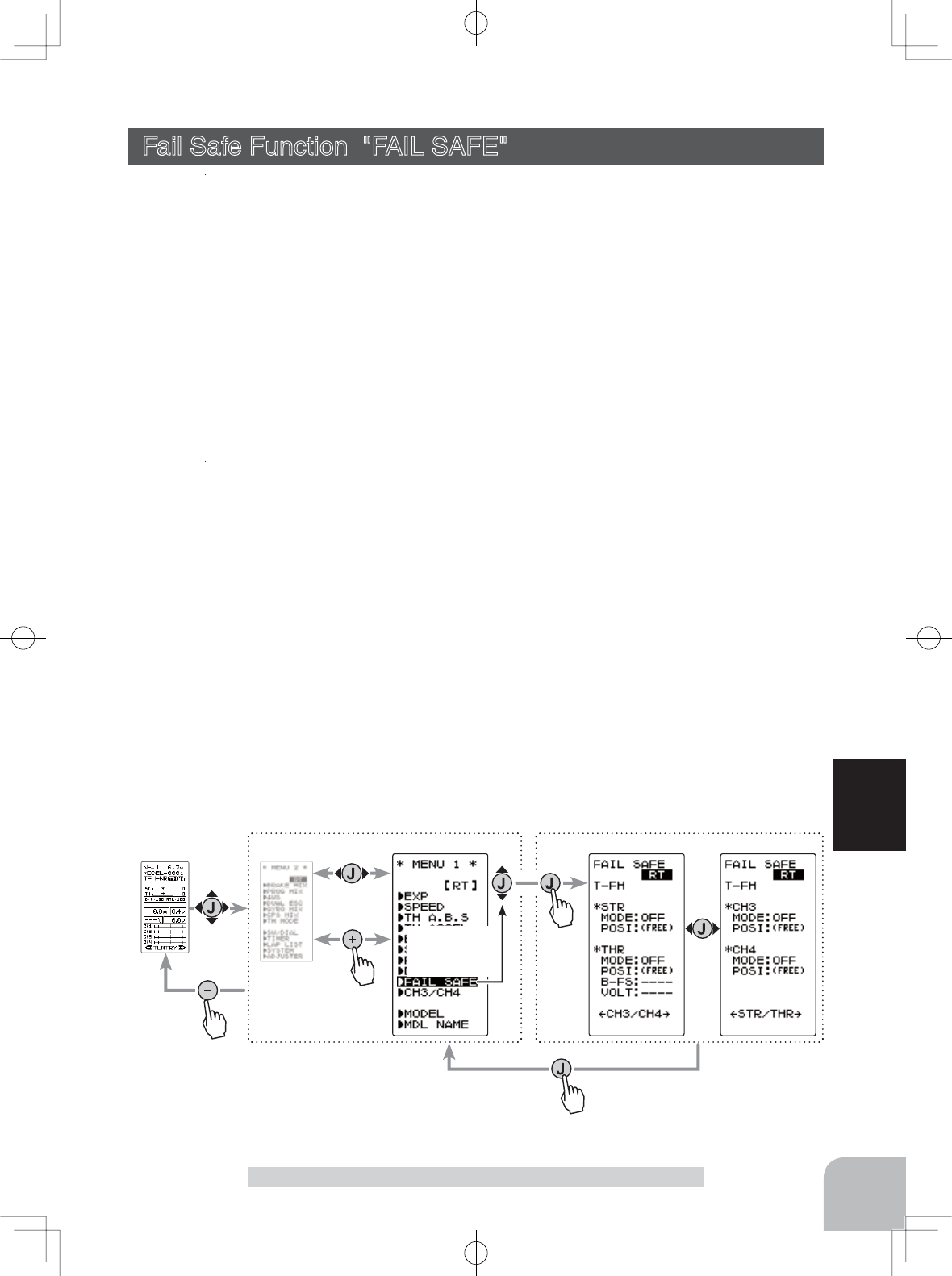
cursor position [RT]
Setting item
MODE :F/S mode selection
POSI :F/S positon set
B-FS :B-FS set (throttle only)
VOLT :B-FS voltage set (throttle only)
57
Function
Fail Safe Function "FAIL SAFE"
Fail Safe Function "FAIL SAFE" (All channel)
Fail Safe Mode (F/S)
This function moves each servo to a preset position when the receiver does not receive a
clear signal from the transmitter.
-When the condition set at "FHSS" is Rx type, fail safe (F/S) can be set only for throttle (TH). Other channels are set to the
normal mode.
-The fail safe data is transferred from the transmitter to the receiver 10 seconds after the transmitter power is turned on. The
GDWDLVWUDQVIHUUHGHYHU\VHFRQGVDIWHUWKDW%HFDUHIXOEHFDXVHQRUPDOO\WKHWUDQVPLWWHUSRZHULVWXUQHGRQ¿UVWDQGWKHUH-
ceiver power is turned on next and the data is transferred for approximately 10 seconds after the receiver power is turned on.
-For gasoline engine cars, for safety we recommend that this fail safe function be used to set the throttle channel in the direc-
tion in which the brakes are applied.
Hold mode (HOLD)
This function holds the servo/s at the position they were in immediately before recep-
tion was lost. This applies to the T-FHSS type (R304SB...,etc.) and the S-FHSS type
(R2104GF...,etc.) receivers only. When the receiver used is an R603GF/2004GF or other
FHSS type, this function is not available.
Off mode (OFF)
In this model the receiver stops outputting a signal to the servos if the transmitter signal
is lost. The servos become effectively unpowered.
The F/S, HOLD, and OFF modes are automatically reset when signals from the trans-
mitter can be received again.
Battery fail safe function (BFS)
If the receiver battery voltage drops below a certain value when this function is enabled,
the throttle servo moves to the position set by fail safe function. When the battery volt-
age recovers, the battery fail safe function is automatically reset.
-This function cannot be used when the throttle (TH) is not set to fail safe (F/S).
-This function is for the T-FHSS type (R304SB...,etc.) and the S-FHSS type (R2104GF...,etc.) receiver only. It cannot be used
with the R603GF and R2004FG and other FHSS type.
Display to "FAIL SAFE" screen by the following method:
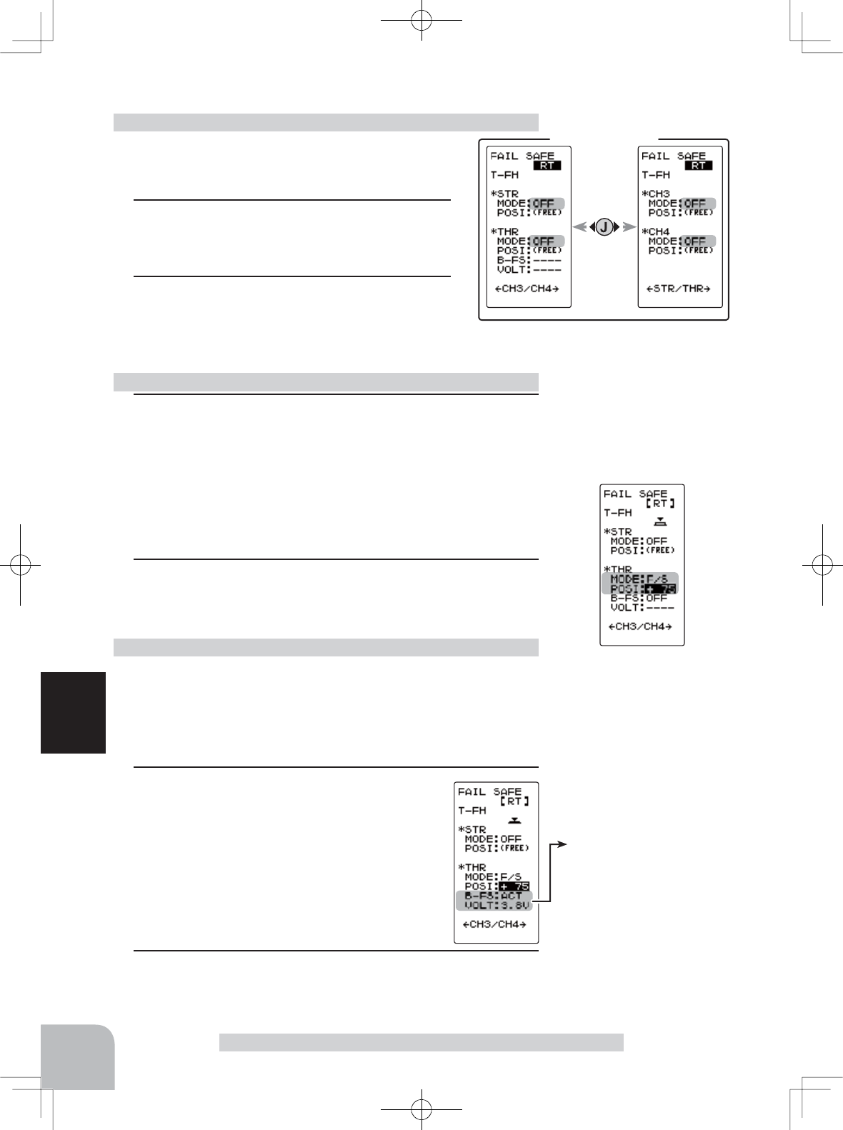
FAIL SAFE screen
Battery fail safe function
OFF, ACT
Initial value: OFF
B-F/S Voltage
3.8, 4.0, 4.2, 4.4, 4.6, 4.8, 5.0,
5.3, 5.6, 5.9, 6.2, 6.5, 6.8, 7.1,
7.4(V)
Initial value 3.8v
Example:
NiMH /NiCd 4cell---3.8V
NiMH /NiCd 6cell---4.4V
LiFe 2cell---4.8V
LiPo 2cell---5.6V
58
Function
Fail Safe Function "FAIL SAFE"
(Preparation)
- Select the channels "MODE" to be set using the
(JOG) button up, down, left, or right operation.
1(Mode selection)
Select the mode by (+) or (-) button.
(Each channel can be individually set.)
2When completed, move the cursor to [RT] us-
ing the (JOG) button, and return to the MENU1
screen by pressing the (JOG) button. When setting fail safe,
set the servo position by the following method.
Fail safe mode selection
(Preparation)
- Select the setting item using the (JOG) button. For Battery F/S
function ON/OF, select "OFF" or "ACT" of "B-FS".
For voltage setting, select RX**v. (The T-FHSS system only. )
The S-FHSS system is fixed at 3.8v.
1(Battery fail safe function ACT/OFF)
BATT-F/S function ACT/OFF and voltage set-
ting which activates the B-F/S function can be
switched by (+) or (-) button.
Battery fail safe function ON/OFF (T-FHSS/ S-FHSS)
1(Servo position setup)
When the fail safe function operates, select the setting item
"POSI" using the (JOG) button. The steering stick, the throt-
tle stick or 3rd, 4th channel dial should be positioned as re-
quired in the event that the failsafe activates. When the (JOG)
button is pressed for about 1 second, the servo position is
displayed and you can confirm that the function was set.
(Each channel can be set similarly.)
2When completed, move the cursor to [RT] using the (JOG) but-
ton, and return to the MENU1 screen by pressing the (JOG)
button.
Fail safe function setup
F/S position setup button
- The (JOG) buttons is pressed
for about 1 second.
F/S mode selection
- Select with the (+) or (-) but-
tons.
F/S mode
OFF, HOLD, F/S
2When completed, move the cursor to [RT] using the (JOG) but-
ton, and return to the MENU1 screen by pressing the (JOG)
button.
+1 ~ +100
-1 ~ -100
Stick operation
Mild
(Negative side)
Quick
(Positive side)
Stick operation
Servo travel
Pres
s
Pres
s
Pres
s
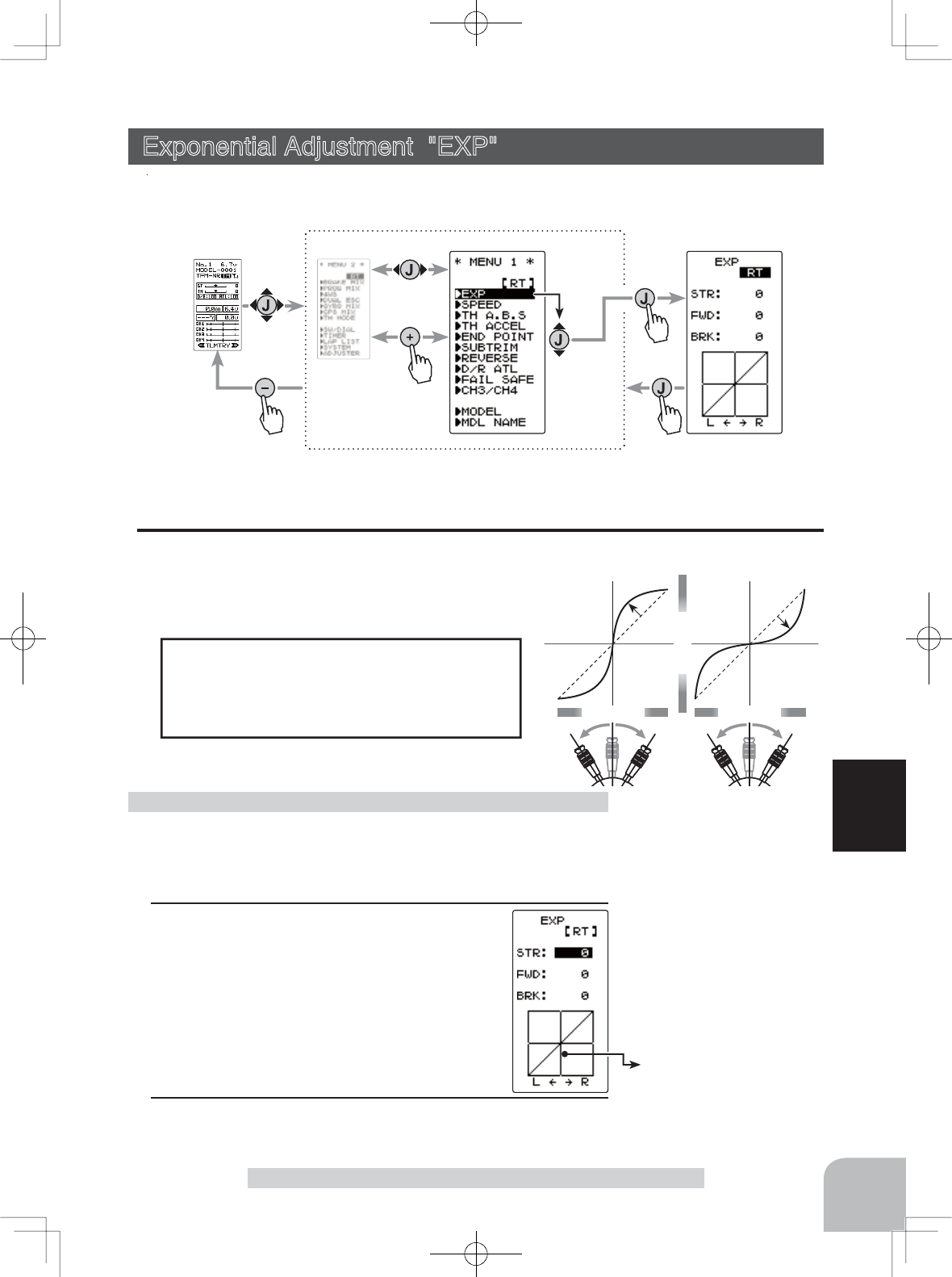
Pres
s
Select
"EXP"
(HOME screen) (MENU 2 screen) (
EXP
screen)
(MENU 1 screen)
Vertical cursor moves in step
with steering stick operation.
59
Function
Exponential Adjustment "EXP"
Exponential Adjustment "EXP" (Steering/ Throttle system)
This function is used to change the sensitivity of the servo around the neutral position.
Display to "EXP" screen by the following method:
(Preparation)
- On the EXP screen, Select the setting item "STR" using the (JOG)
button.
1When you want to speed up initial steering
operation, use the (+) button to adjust the +
side. When you want to make steering opera-
tion gentler initially, use the (-) button to adjust
the - side.
Steering EXP adjustment
When the setting is not determined, or the
characteristics of the model are unknown,
start with 0%. (When EXP is set to 0%, servo
movement is linear.)
STR (Steering EXP)
This function is used to change the sensitivity of the
steering servo around the neutral position. It has no ef-
fect on the maximum servo travel.
Racers Tip
Adjustment range
-100~0~+100
Adjust button
- Adjust with the (+) and (-) but-
tons.
- Return to the initial value "0" by
pressing the (+) and (-) buttons
simultaneously for about 1 sec-
ond.
2When completed, return to the MENU1 screen by pressing
the (JOG) button.
Setting item
STR :Steering
FWD :Throttle forward side
BRK :Throttle brake/ reverse side
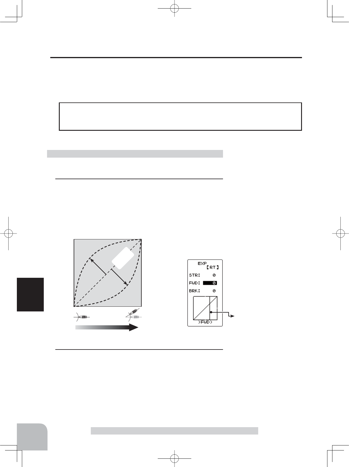
0
Normal
+1 ~ +100
Stick operation
Faster
-1 ~ -100
Gentler
Servo travel
Vertical cursor moves in step
with throttle stick operation.
60
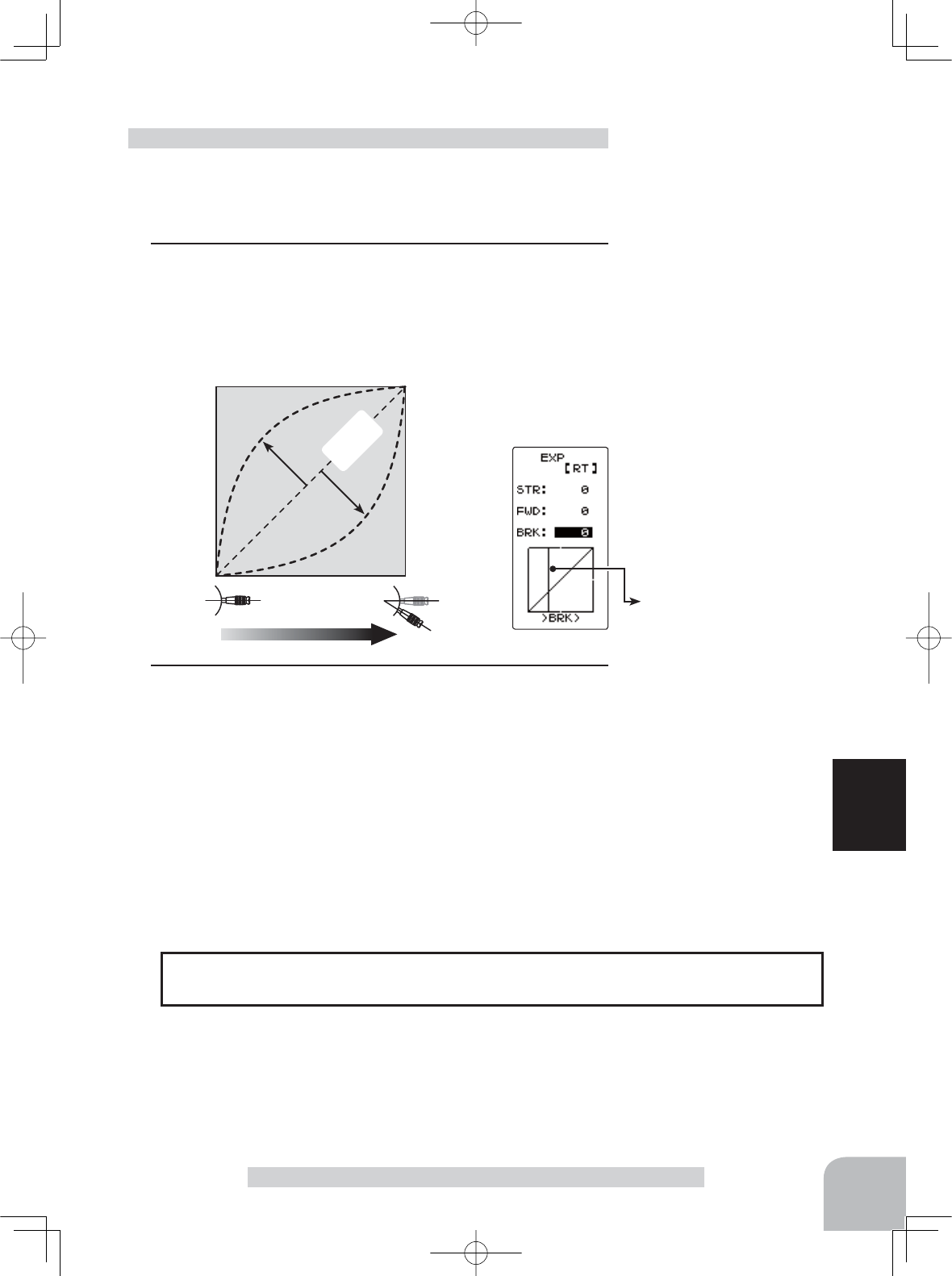
Function
Exponential Adjustment "EXP"
FWD (Throttle Forward Side EXP) BRK (Throttle Brake Side EXP)
This function is used to change the sensitivity of the throttle/brake servo/ESC around
the neutral position. It has no effect on the servo maximum operation amount.
When the course conditions are good and the surface has good grip, set each curve to
the + side (faster initial response). When the road surface is slippery and the tyres do
not have good grip, set each curve to the - side (gentler initial response).
Advice
Adjustment range
-100 ~ 0 ~ +100%
Adjust button
Adjust with the (+) and (-) but-
tons.
- Return to the initial value "0" by
pressing the (+) and (-) buttons
simultaneously for about 1 sec-
ond.
(Preparation)
- On the EXP screen make the following adjustments:
1Select the setting item "FWD" using the (JOG) button up or
down operation.
Use the (+) button to adjust for a faster initial throttle re-
sponse or use the (-) button for a gentler throttle response.
Full throttle EXP adjustment
2When completed, return to the MENU1 screen by pressing
the (JOG) button.
0
Normal
+1 ~ +100
Stick operation
Faster
-1 ~ -100
Gentler
Servo travel
Vertical cursor moves in step
with throttle stick operation.
*This function is not available in "TH-STK : F10 mode"
61
Function
Exponential Adjustment "EXP"
(Preparation)
- On the EXP screen make the following adjustments:
1Select the setting item "BRK" using the (JOG) button up or
down operation.
Use the (+) button to adjust for a faster initial throttle re-
sponse or use the (-) button for a gentler throttle response.
Throttle brake side EXP adjustment
Adjustment range
-100 ~ 0 ~ +100%
Adjust button
Adjust with the (+) and (-) but-
tons.
- Return to the initial value "0" by
pressing the (+) and (-) buttons
simultaneously for about 1 sec-
ond.
The steering and throttle EXP adjustment (RATE) can be controlled with digital dial
or digital trim with the function select
switch dial
function.
Dial / Trim Setting
2When completed, return to the MENU1 screen by pressing
the (JOG) button.
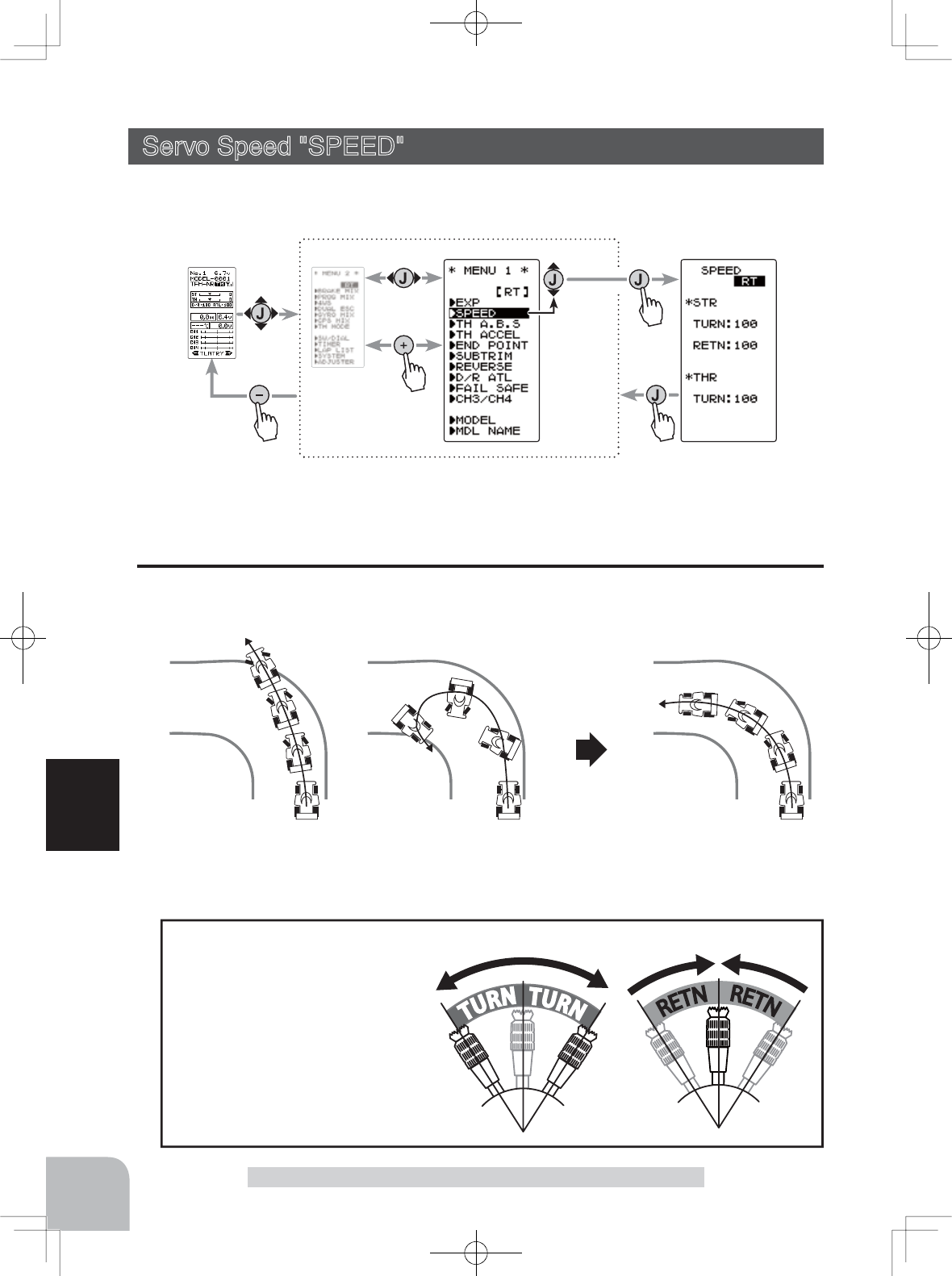
Without "SPEED" With "SPEED"
Under steering
Smooth corneringSpin
(HOME screen) (MENU 2 screen) (
SPEED
screen)
(MENU 1 screen)
Pres
s
Pres
s
Pres
s
Pres
s
Select
"SPEED"
62
Function
Servo Speed "SPEED"
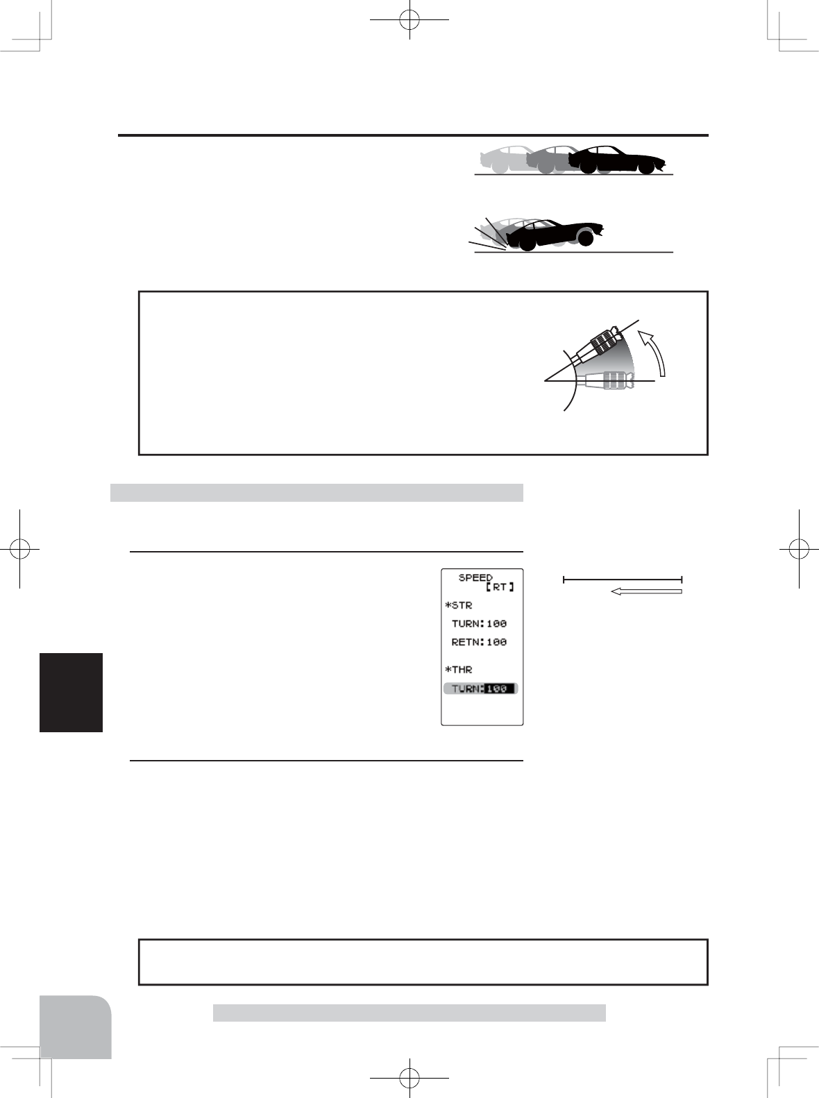
- This function limits the maximum speed of the steering servo. (Delay function)
- The steering speed when the
steering stick is operated (TURN
direction) and returned (RETN
direction) can be independently
set.
- If the steering stick is moved
more slowly than the set speed,
the steering servo is not affected.
Operation
Servo Speed "SPEED" (Steering system)
This function is used to change the servo speed.
Display to "SPEED" screen by the following method:
STR (Steering Speed)
Over quick steering may cause momentary understeer, loss of speed or even a spin -
the steering speed function can be effective in these cases.
Setting item
STR TURN :Steering application
STR RETN :Steering return to neutral
THR TURN :Throttle application
63
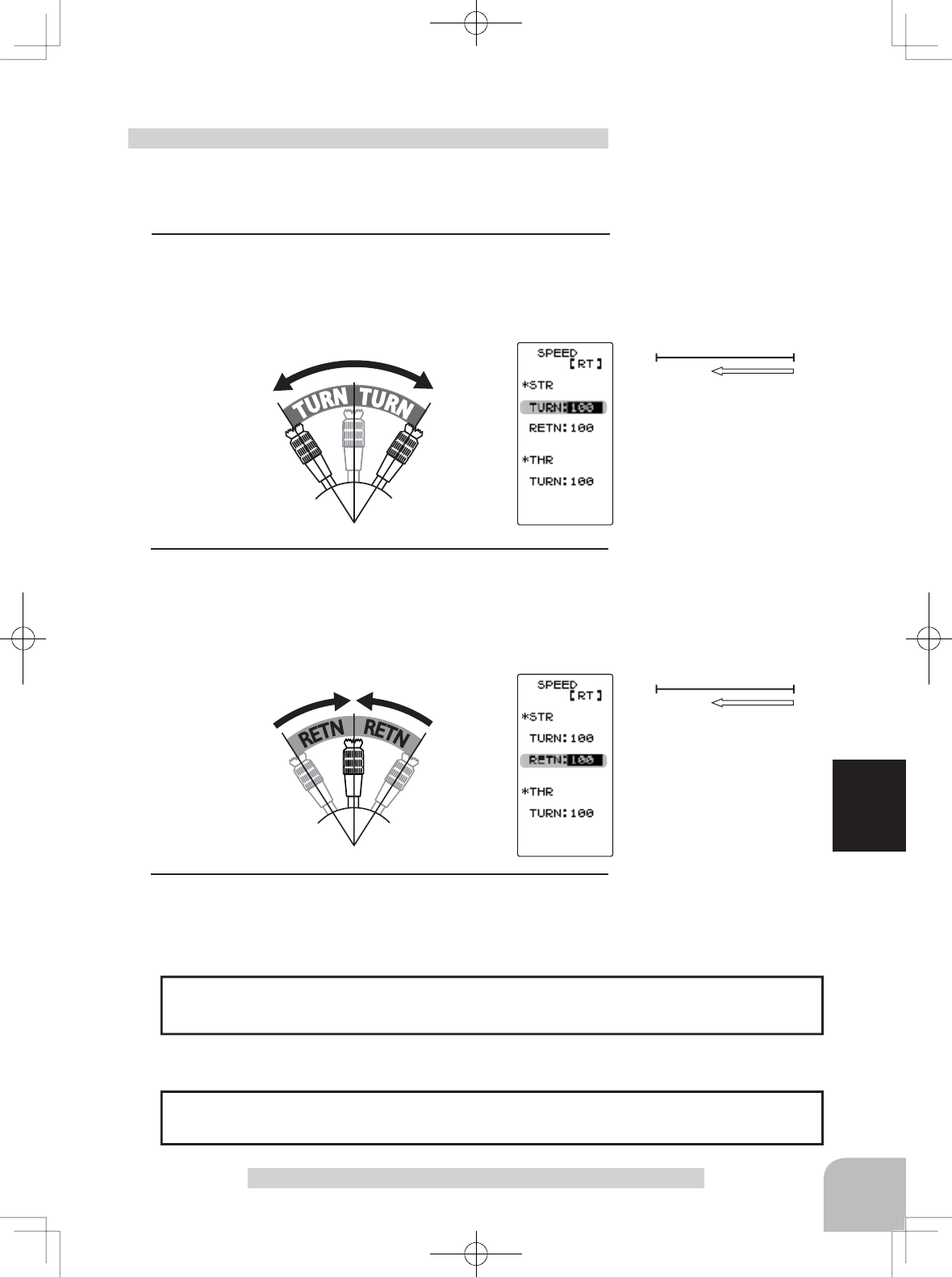
Function
(Preparation)
- On the SPEED screen make the following adjustments:
1"TURN" direction adjustment
On the SPEED screen, Select the setting item STR "TURN"
using the (JOG) button up or down operation and use the (+)
or (-) buttons to adjust the delay amount.
Steering Speed adjustment
100%1%
Servo operation is delayed.
100%1%
Servo operation is delayed.
- Onroad TURN side: Approx. 50~80% RETURN side: Approx. 60~100%
- Offroad TURN side: Approx. 70~100% RETURN side: Approx. 80~100%
Setting example (Steering servo: BLS471SV / BLS371SV) . . . (Setting criteria)
Adjust button
- Adjust with the (+) and (-) but-
tons.
- Return to the initial value "100"
by pressing the (+) and (-) but-
tons simultaneously for about 1
second.
Adjust button
- Adjust with the (+) and (-) but-
tons.
- Return to the initial value "100"
by pressing the (+) and (-) but-
tons simultaneously for about 1
second.
Adjustment range
1~100% (each direction)
At 100%, there is no delay.
Adjustment range
1~100% (each direction)
At 100%, there is no delay.
Servo Speed "SPEED"
2"RETN" direction adjustment
Select the setting item STR "RETN" using the (JOG) button
up or down operation and use the (+) or (-) buttons to adjust
the delay amount.
3When completed, return to the MENU1 screen by pressing
the (JOG) button.
The steering speed adjustment "TURN" and "RETN" can be controlled with digital dial
or digital trim with the function select
switch dial
function.
Dial / Trim Setting
high
neutral
With "SPEED": Quick start without skidding
Without "SPEED": Slow start due to skidding
64
Function
Servo Speed "SPEED"
(Preparation)
- On the SPEED screen make the following adjustments:
1 (Delay adjustment)
On the SPEED screen, Select the setting item
THR "TURN" using the (JOG) button up or
down operation and use the (+) or (-) buttons
to adjust the delay amount.
Throttle Speed adjustment
Adjust button
- Adjust with the (+) and (-) but-
tons.
- Return to the initial value "100"
by pressing the (+) and (-) but-
tons simultaneously for about 1
second.
The throttle speed adjustment
can be controlled with digital dial or digital trim with
the function select
switch dial
function.
Dial / Trim Setting
-Throttle servo (ESC) operation is slowed when the throttle
stick is pushed forward so that the wheels will not spin
even if the throttle is opened faster than required.
This function is not active when the stick is pulled back for
brake/reverse.
Operation
THR (
Throttle
Speed)
Sudden throttle stick operation on a slippery
surface will cause the wheels to spin, resulting
in poor acceleration. Setting the throttle speed
function reduces wasteful battery consumption
while at the same time enabling smooth, enjoy-
able operation.
100%1%
Servo operation is delayed.
Adjustment range
1~100%
At 100%, there is no delay.
2When completed, return to the MENU1 screen by pressing
the (JOG) button.
(HOME screen) (MENU 2 screen) (
TH ACCEL
screen)(MENU 1 screen)
Pres
s
Pres
s
Pres
s
Pres
s
Select
"TH ACCEL"
*This function is not
available in "TH-STK :
F10 mode"
65
Function
Throttle Acceleration "TH ACCEL"
FWRD BRAKE
Servo travel
0%
50%
100%
0%
50%
100%
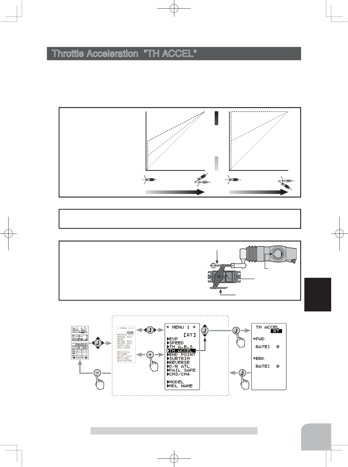
- Operation near the throt-
tle trigger neutral position
becomes an abrupt rise.
- The forward and brake
sides can be set separately.
- When the brake mixing
function is set, the CH3/
CH4 brake can also be set.
Operation
Throttle Acceleration "TH ACCEL" (Throttle system)
The throttle servo will "jump" to a preset position at its maximum possible speed. Un-
like exponential, which adjusts the whole throttle movement into a curve, throttle ac-
celeration simply "jumps" away from neutral and then leaves the remaining response
linear.
The standard value (100% point) of this setup affects the operation amount set by
throttle EPA function.
Set value
Carburetor
Brake side
Servo horn
Clearance
For GP cars, the linkage must have a clearance
because one servo controls the engine carbure-
tor and brake. Thus, there is a noticeable time
delay at both the forward and brake sides. Sharp
response comparable to that of electric motor cars
is obtained by reducing this clearance at the trans-
mitter side.
Convenient usage method
Display to "TH ACCEL" screen by the following method:
Setup item
FWR RATE :Forward side acceleration
BRA RATE :Brake side acceleration
66
Function
Throttle Acceleration "TH ACCEL"
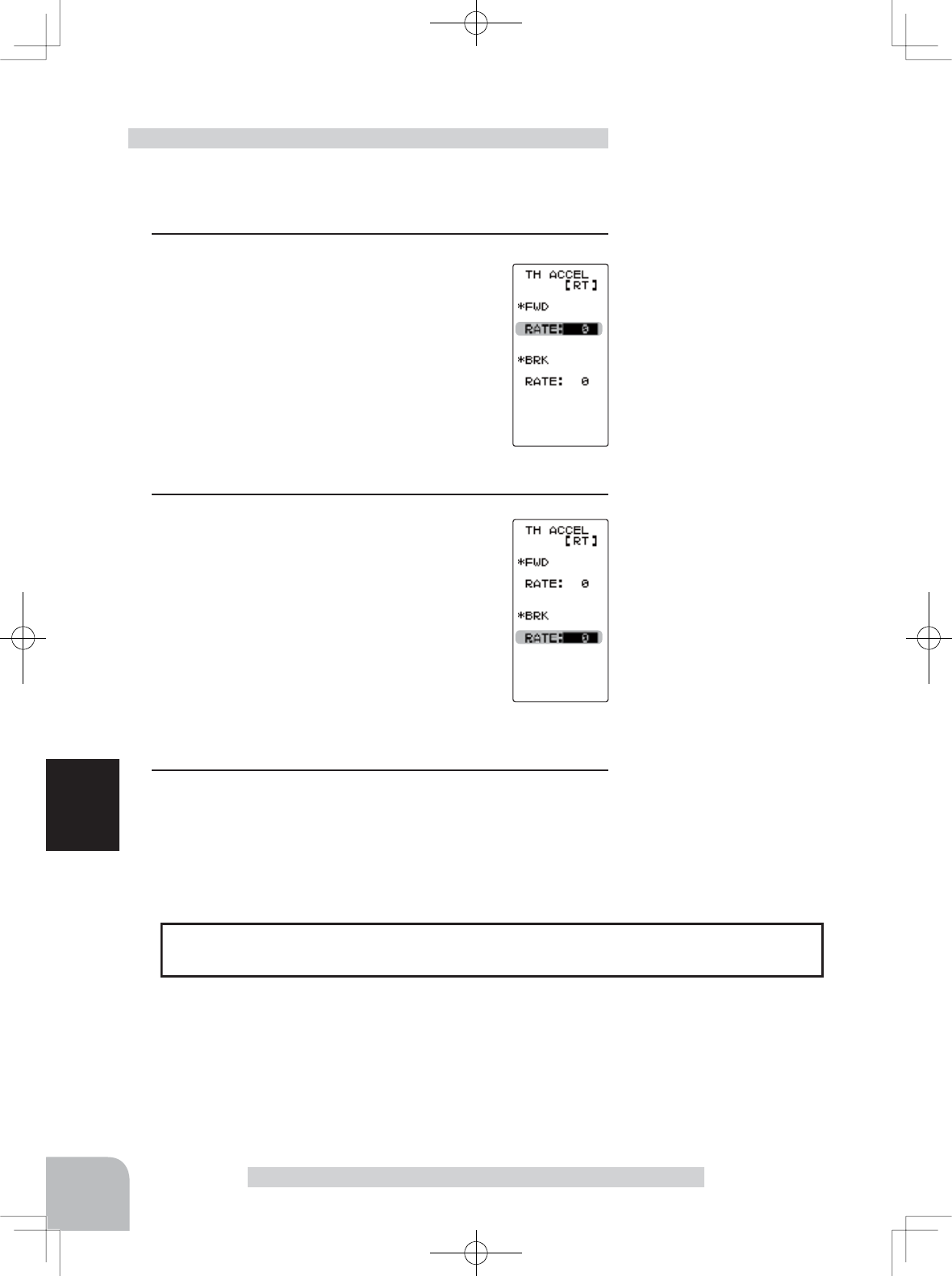
(Preparation)
- On the TH ACCEL screen make the following adjustments:
1(Forward acceleration amount adjustment)
Select the setting item FWD "RATE" using the
(JOG) button up or down operation and use
the (+) and (-) buttons to adjust the accelera-
tion amount.
"0" :No acceleration
"100" :Maximum acceleration (Approximately 1/2 of the forward side throttle angle)
2(Brake side acceleration amount adjustment)
Select the setting item BRK "RATE" using the
(JOG) button up or down operation and use
the (+) and (-) buttons to adjust the accelera-
tion amount.
"0" :No acceleration
"100" :Maximum acceleration (Brake side maximum throttle angle)
4When completed, return to the MENU1 screen by pressing
the (JOG) button.
Throttle acceleration adjustment
The throttle acceleration adjustment amount (FWD), (BRK) can be controlled with
digital dial or digital trim with the function select
switch dial
function.
Dial / Trim Setting
Adjust button
Adjust with the (+) and (-) but-
tons.
- Return to the initial value "0" by
pressing the (+) and (-) buttons
simultaneously for about 1 sec-
ond.
Adjust button
Adjust with the (+) and (-) but-
tons.
- Return to the initial value "0" by
pressing the (+) and (-) buttons
simultaneously for about 1 sec-
ond.
Forward acceleration amount
(FWD)
0~100
Initial value: 0
Brake side acceleration amount
(BRK)
0~100
Initial value: 0
(HOME screen) (MENU 2 screen) (
TH A.B.S
screen)(MENU 1 screen)
Pres
s
Pres
s
Pres
s
Pres
s
Select
"TH A.B.S"
*This function is not available in "TH-STK : F10 mode".
67
Function
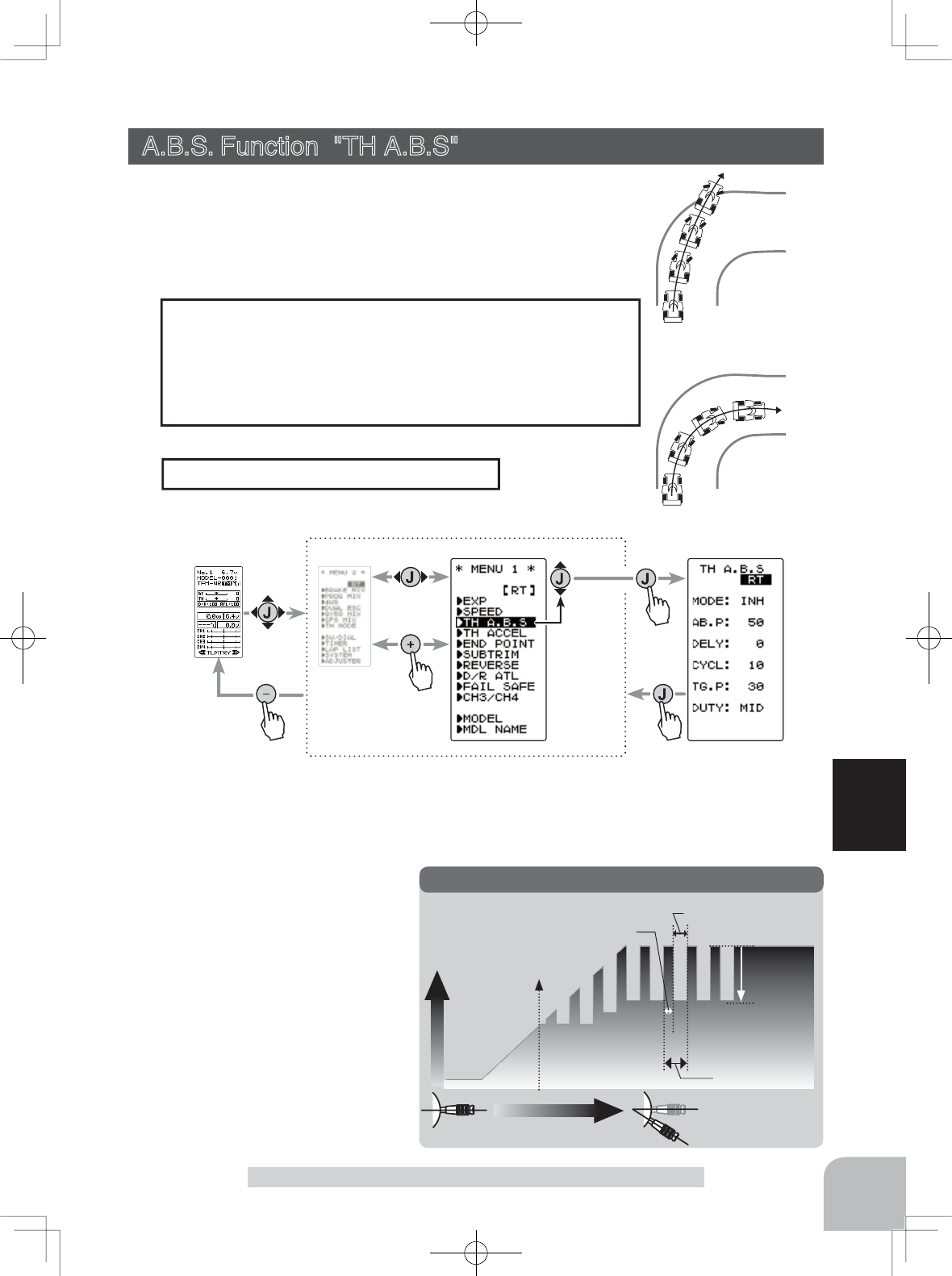
Servo travel
Stick operation
AB.P
(Amount of
brake return)
TG.P (Starting point)
CYCL (Cycle)
DUTY (duty): X and Y ratio
X: (Brake application time)
Y: (Brake return time)
A.B.S
- AB.P : Amount of brake return
Sets the rate at which the servo
returns versus stick operation
for brake release. When set to
0%, the ABS function is not
performed. When set to 50%,
the servo returns 50% (1/2) of
the stick operation amount and
when set to 100%, the servo re-
turns to the neutral position.
With A.B.S.
Without A.B.S.
A.B.S. Function "TH A.B.S"
- When the brakes are applied, the throttle servo will pulse
intermittently. This will have the same effect as pumping the
brakes in a full size car.
- The brake return amount, delay amount, pulse cycle, and
brake duty can be adjusted.
Operation
A.B.S. Function "TH A.B.S" (Throttle system)
When the brakes are applied while cornering with a 4 Wheel
Drive or other type of vehicle, understeer may occur. This under
-
steer can be eliminated and cornering improved using this func-
tion.
During ABS operation, the LED blinks.
Operation display
Display "TH A.B.S" screen by the following method:
Setup items
MODE : Function ON/Off
AB.P : Brake return amount
DELY : Delay amount
CYCL : Cycle speed
TG.P : Starting point
DUTY : Cycle duty ratio
68
Function
AB.P
(Amount of brake return)
AB.P
Servo travel
A.B.S. Function "TH A.B.S"
- DELY : Delay
Sets the delay from brake operation to ABS operation. When set to 0%, the ABS func-
tion is activated without any delay. At 50%, the ABS function is activated after a delay
of approximately 1 second and at 100%, the ABS function is activated after a delay of
approximately 2 seconds.
- CYCL : Cycle speed
Sets the pulse speed (cycle). The smaller the set value, the faster the pulse cycle.
- TG.P : Starting point
Sets the starting point at which the ABS function begins to operate at brake operation.
- DUTY : Cycle duty ratio
Sets the proportion of the time the brakes are applied and the time the brakes are re-
leased by pulse operation. The ratio can be set to HIGH, MID or LOW.
- MODE : Function ON/OFF
ABS function ON/OFF setting. When using the ABS function, set to "ACT(ON)".
1(Function ON/OFF)
Select the setting item "MODE" using the (JOG) button
up or down operation. Set the function to the active state
by pressing the (+) or (-) button.
"INH(OFF)" :Function OFF
"ACT(ON)" :Function ON
"ACT(OFF)" :Switch OFF when setting switches
2(Brake return amount adjustment)
Select the setting item "AB.P"
using
the (JOG) button up or
down operation
. Use the (+)
or (-) button to adjust the re-
turn amount.
"0" :No return
"50" :Return to the 50% position of the brake operation amount
"100" :Return to the neutral position.
3(Delay amount setup)
Select the setting item "DELY" using the (JOG) button up
or down operation. Use the (+) or (-) button to adjust the
delay amount.
"0" :A.B.S. function performed without any delay
"50" :A.B.S function performed after an approximate 1 sec delay.
"100" :A.B.S. function performed after an approximate 2 secs delay.
A.B.S function adjustment
- Brake return amount (AB.P)
is influenced by the "EXP"
rate on the brake side.
Delay amount (DELY)
0 ~ 100
Initial value: 0
Adjustment buttons
- Use the (+) and (-) buttons to
make adjustments.
- Return to the initial value by
pressing the (+) and (-) but-
tons simultaneously (approx.
1 sec).
Adjustment buttons
- Use the (+) and (-) buttons to
make adjustments.
- Return to the initial value by
pressing the (+) and (-) but-
tons simultaneously (approx.
1 sec).
Brake return amount (AB.P)
0 ~ 50 ~ 100
Initial value: 50
Function ON/OFF (MODE)
INH(OFF), ACT(ON,OFF)
Select button
- Select with the (+) or (-) but-
tons.
CYCL
Servo travel
CYCL (Cycle)
Cycle speed (CYCL)
1 ~ 30
Initial value: 10
DUTY
Servo travel
DUTY (duty): X and Y ratio
X: (Brake
application time)
Y: (Brake return time)
Duty ratio (DUTY)
LOW - MID - HIGH
Initial value: MID
Adjustment buttons
- Use the (+) and (-) buttons to
make adjustments.
- Return to the initial value by
pressing the (+) and (-) but-
tons simultaneously (approx.
1 sec).
TG.P
Servo travel
TG.P
(Starting point)
TGP
Brake side
Neutral
Starting point (TG.P)
10 ~ 100
Initial value: 30
Adjustment buttons
- Use the (+) and (-) buttons to
make adjustments.
- Return to the initial value by
pressing the (+) and (-) but-
tons simultaneously (approx.
1 sec).
69
Function
Adjustment buttons
- Use the (+) and (-) buttons to
make adjustments.
- Return to the initial value by
pressing the (+) and (-) but-
tons simultaneously (approx.
1 sec).
A.B.S. Function "TH A.B.S"
Use SW1 or SW2 to switch the A.B.S. function ON/OFF.
See the function select
switch dial
function.
Switch setting
The brake return amount (AB.P), delay amount (DELY) and cycle (CYCL) can be con-
trolled with digital dial or digital trim with the function
switch dial
function.
Dial / Trim Setting
4(Cycle speed adjustment)
Select setting item "CYCL"
using the (JOG) button up or
down operation. Use the (+) or
(-) button to adjust the pulse
speed (cycle).
- The smaller the set value, the faster the pulse speed.
5(Starting point setup)
Select setting item "TG.P" using
the (JOG) button up or down
operation. Use the (+) or (-) but-
ton to adjust the operation point.
- Sets the throttle stick position at which the A.B.S. function is performed.
The number is the % display with the full brake position being 100.
6(Cycle duty ratio setup)
Select setting item "DUTY"
using the (JOG) button up or
down operation. Use the (+) or
(-) button to adjust the duty ra-
tio.
"LOW" :Brake application time reduced to minimum.(Brakes lock with difficulty)
"HIGH" :Brake application time increased to maximum. (Brakes lock easily)
(Remark) For low grip, set at the LOW side and for high grip, set at the
HIGH side.
7When completed, return to the MENU1 screen by pressing
the (JOG) button.
70
Function
A.B.S. Function "TH A.B.S"
When the T4GRS is used with the Futaba fail safe unit (FSU), it will operate as de-
scribed below. However, FSU-1 cannot be used in the high speed mode.
- When the FSU is connected to the throttle channel, and the A.B.S. function has been
DFWLYDWHGWKH)68/('ZLOOÀDVKHDFKWLPHWKHVHUYRRSHUDWHV7KHUHDVRQIRUWKLVLV
that the FSU responds to sudden data changes caused by A.B.S. function pumping op-
eration. It does not mean that the fail safe function is activated. The servo will not be
affected.
Fail Safe Unit
- Basic setting
AB.P: Approx. 30% (If this value is too high, the braking distance will increase.)
CYCL: 5~7
DUTY: (When grip is low: LOW side, when grip is high: HIGH side)
DELY: 10~15%
TG.P: Approx. 70%
- When the wheels lock or the car spins, when the brakes are applied fully
AB.P: Increase from 30%
DUTY: Shift to "LOW" side
DELY: Reduce the delay
- When the braking is poor and thus the braking distance extended when the brakes are
applied fully
AB.P: Decrease from 30%
DUTY: Shift to "HIGH" side
DELY: Increase the delay
Example of A.B.S. function setting when BLS371SV used
(There will be a slight difference depcompleted on the state of the linkage.)
ABS can be independently set for the brakes which are controlled by the 3rd CH and
4th CH by using the brake mixing (BRAKE MIX) function described. For more infor-
mation, read the brake mixing (BRAKE MIX) item.
1/5 scale car and others with independent brakes and ABS
Pres
s
Pres
s
(HOME screen) (MENU 2 screen) (CH3/CH4 screen)
Pres
s
(MENU 1 screen)
Pres
s
Select
"
CH3/CH4
"
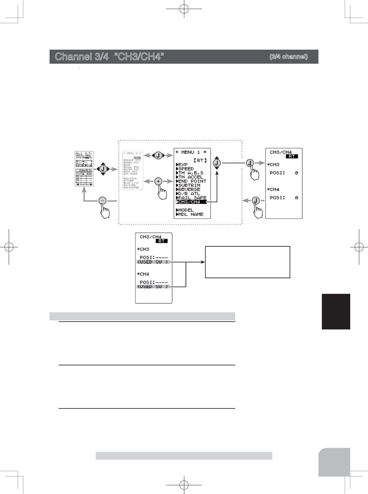
Display when CH3/4 is as-
signed to a switch by the switch
dial function. Cannot adjust the
CH3/4 via the screen.
71
Function
Channel3/4 "CH3/CH4"
Channel 3/4 "CH3/CH4" (3/4 channel)
The channel 3/4 servo position can be set from the transmitter. When CH3 is as-
signed to a dial by the switch dial function , this setting is linked to that dial.
When CH3/4 is not assigned to a dial, it can be set with this screen.
When CH3/4 is assigned to a switch by the switch dial function, you cannot adjust
the CH3/4 via the screen.
Display "CH3/CH4" screen by the following method:
1 (Function selection)
On each CH3/CH4 screen select CH3 "POSI" or CH4 "POSI"
using the (JOG) button up or down operation.
2 (Position setting/rate adjustment)
Use the (+) and (-) buttons to adjust the channel 3 or chan-
nel 4 position.
3When completed, return to the MENU1 screen by pressing
the (JOG) button.
Rate / position adjustment on channel menu screen
Adjust button
- Adjust with the (+) and (-) but-
tons.
- Return to the initial value
"100" by pressing the (+) and
(-) buttons simultaneously for
about 1 second.
Channel 3 position (POSI)
Channel 4 position (POSI)
0~100%
Initial value: 0
Pres
s
Pres
s
(HOME screen) (MENU 2 screen) (D/R ATL screen)
Pres
s
(MENU 1 screen)
Pres
s
Select
"
D/R ATL
"
72
Function
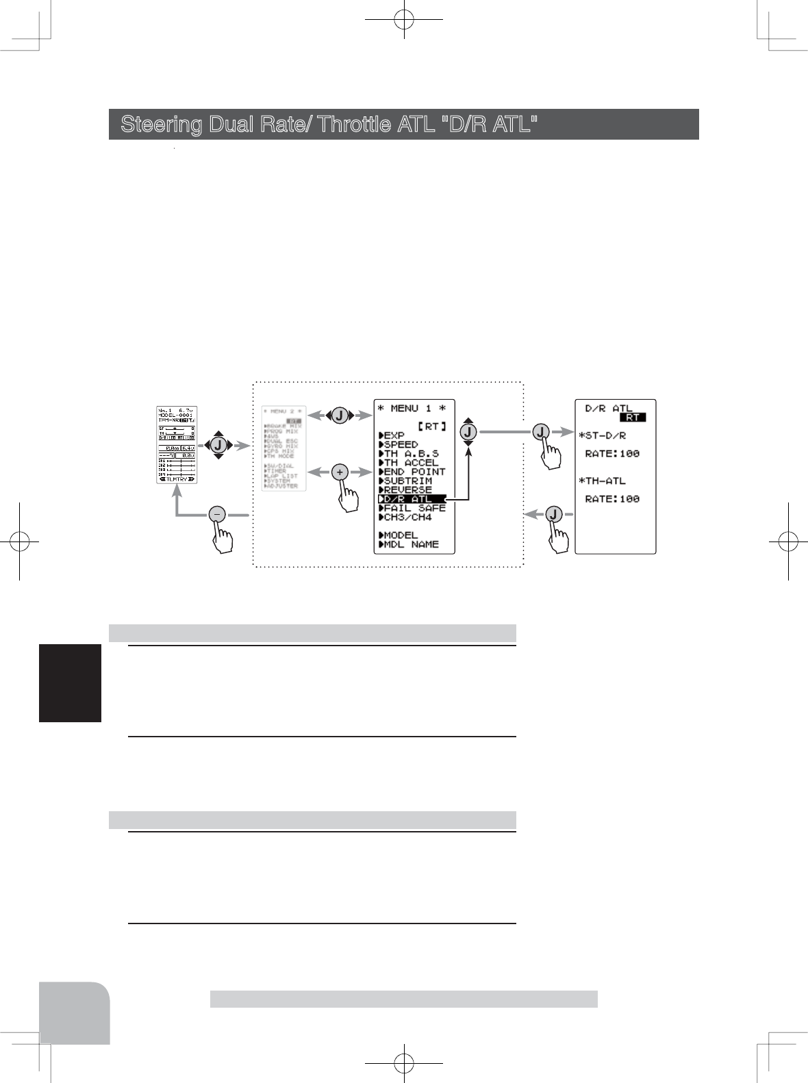
Steering Dual Rate/ Throttle ATL "D/R ATL"
Steering Dual Rate/ Throttle ATL "D/R ATL"
D/R (Steering dual rate)
The steering left and right servo travels are adjusted simultaneously. This setting is
linked to transmitter DT3. When DT3 is assigned another function, dual rate can be
adjusted with this screen.
ATL (Throttle ATL)
This function decreases the set value when the braking effect is strong and increas-
es the set value when the braking effect is weak. This function is linked to transmit-
ter DT4. When DT4 is assigned another function, this function can be set with this
screen.
Display "D/R ATL" screen by the following method:
1(Dual rate adjustment)
Select the setting item ST-D/R "RATE" using (JOG) button up
or down operation. Adjust the servo travel with the (+) and (-)
buttons.
2When completed, return to the MENU1 screen by pressing
the (JOG) button.
1(Brake amount adjustment)
Select the setting item TH-ATL "RATE" using (JOG) button
up or down operation. Adjust the servo travel with the (+) and
(-) buttons.
2When completed, return to the MENU1 screen by pressing
the (JOG) button.
Dual rate adjustment
ATL function adjustment
Adjust button
- Adjust with the (+) and (-) but-
tons.
- Return to the initial value "100"
by pressing the (+) and (-) but-
tons simultaneously for about 1
second.
Adjust button
- Adjust with the (+) and (-) but-
tons.
- Return to the initial value "100"
by pressing the (+) and (-) but-
tons simultaneously for about 1
second.
D/R rate (RATE)
0~100%
Initial value: 100
ATL rate (RATE)
0~100%
Initial value: 100
*This function is not available in "TH-STK : F10 mode".
Pres
s
Pres
s
Pres
s
Pres
s
Select
"
SW/DIAL"
(HOME screen) (MENU 1 screen) (SW/DIAL screen)
(MENU 2 screen)
73
Function
Function Select Trim Dial “TRIM DIAL”
*Function selection
*Step amount setting
*Direction of operation setting
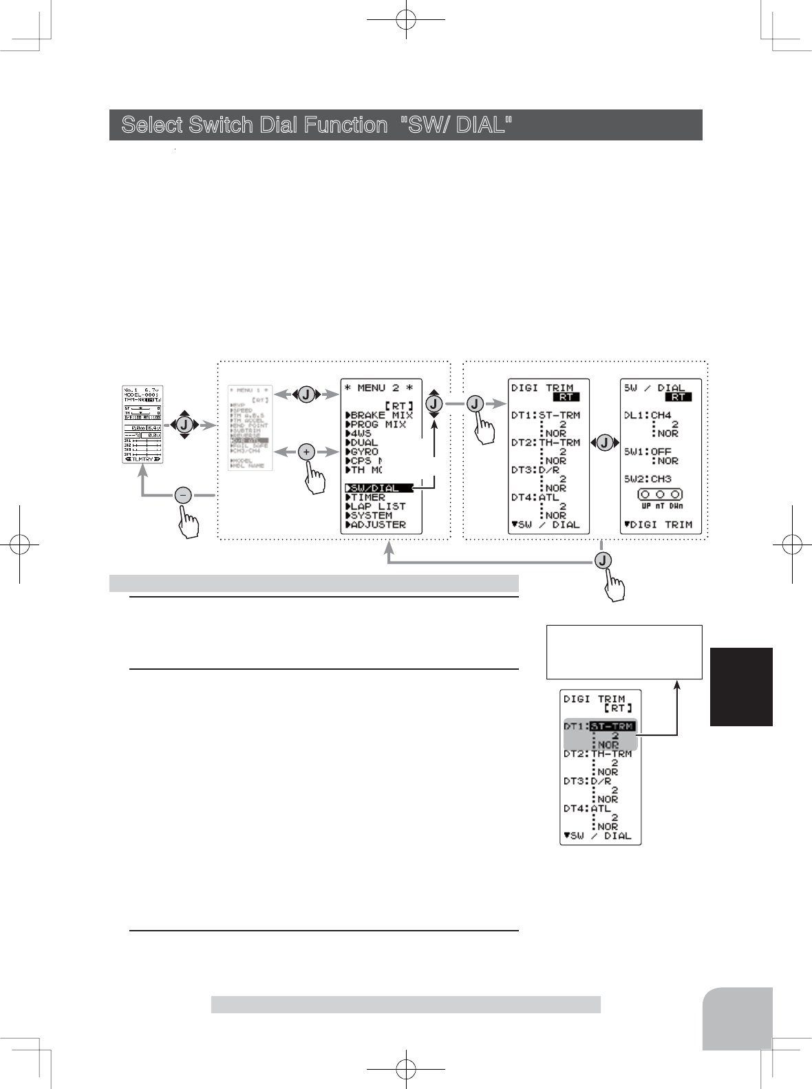
Select Switch Dial Function "SW/ DIAL"
Selection of the function to be performed by digital trim (DT1, DT2, DT3, DT4)
dial (DL1) and switch (SW1, SW2).
-
The functions that can be assigned to dial, digital trim and switch are listed on the next page.
- The
dial and digital trim step
amount can be adjusted. (The relationship between set value
and step amount is shown in the table on the next page.)
- The direction of operation of the servos can be reversed. (NOR/REV)
- SW1 alternate operation (operation which switches between ON and OFF each time the
switch is pressed) is possible.
NOR (Normal) -ON only while pressed, OFF when released.
ALT (Alternate) -Switched between ON and OFF each time pressed.
Display "SW/DIAL" screen by the following method:
1 (Setting dial/trim selection)
Select the dial or trim you want to set using the (JOG) button
up or down operation.
2 (Function setting)
Select the function with the (+) or (-) button.
- Refer to the list on the next page for the abbreviations of the functions.
(Step amount setting)
Select the step amount you want to set using the (JOG) but-
ton up or down operation. Use the (+) or (-) button to set the
step amount.
- Refer to the next page for the relationship between set value and step amount.
(Changing the direction of operation)
Select the Direction of operation you want to set using the
(JOG) button up or down operation. Use the (+) or (-) button
to trim/dial the direction.
3When completed, return to the MENU1 screen by pressing
the (JOG) button.
Function select dial/trim setting
Adjust button
Adjust with the (+) and (-)
buttons.
- Return to the initial value "2"
by pressing the (+) and (-)
buttons simultaneously for
about 1 second.
Adjust button
Adjust with the (+) and (-) but-
tons.
SW1 function selection
Direction of operation set-
ting
SW2 function selection
ON/OFF position is dis-
played.
74
Function
Abbreviation
used on setup
screen
Function name, etc.
D/R Dual rate function
ATL ATL function
EXP-ST Steering EXP
EXP-FW Throttle EXP (Forward side)
EXP-BK Throttle EXP (Brake side)
SPD-TN Steering speed (Turn side)
SPD-RN Steering speed (Return side)
ABS.PS A.B.S. function (Return amount)
ABS.DL A.B.S. function (Delay)
CYCLE A.B.S. function (cycle speed)
ACC-FW Throttle acceleration (Forward side)
ACC-BK Throttle acceleration (Brake side)
TH-SPD Throttle speed
ST-TRM Steering trim
TH-TRM Throttle trim
CH3 Channel 3
CH4 Channel 4
SUBTR1 Sub trim (CH1)
SUBTR2 Sub trim (CH2)
SUBTR3 Sub trim (CH3)
SUBTR4 Sub trim (CH4)
IDLE Idle up function
ESC-RT Dual ESC mixing (4ch ESC rate)
TH-OFF Throttle off (engine cut)
PMX-A Program mixing (RGHT/BRAK/DOWN sides)
PMX-B Program mixing (LEFT/FWRD/UP sides)
BK3-RT Brake mixing (3ch brake rate)
BK4-RT Brake mixing (4th brake rate)
4WS-RT 4WS mixing (3ch steering rate)
ESC-MD Dual ESC mixing (Drive mode select)
GYRO Gyro mixing (Gain rate)
OFF Not used
Set table functions (DL1, DT1/DT2/DT3)
(Setting range: 1~10, 20, 30, 40, 50,
100, 2P)
-Steering trim/throttle trim
When set to the minimum "1", the total
trim operating width is 200 clicks. For
"100", the total operating width is 2 clicks
and for 2P, the total operating width is 1
click.
-Rate, etc. setting
This is the % value which is operated by
1 click relative to the set value of each
rate. Since the total operating width of
functions having a rate of -100~0~+100
is 200%, when set to "100", the total op-
erating width is 2 clicks. Since the total
operating width of functions with a 0~100
rate is 100%, "100" and 2P are operated
by 1 click.
-Channel 3/4
When set to the minimum "1", the to-
tal operating width of channel 3 is 200
clicks. For "100", the total operating with
is 2 clicks and 2P is operated by 1 click.
Relationship between set value
and step amount
Function Select Trim Dial "TRIM DIAL"
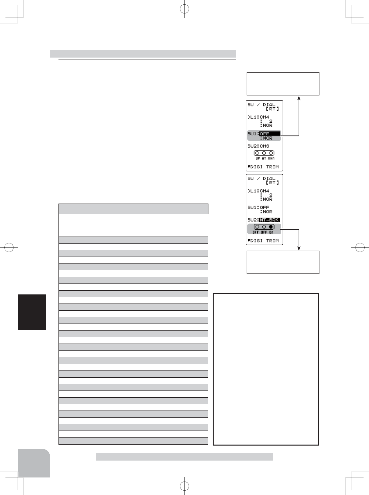
1 (Setting SW selection)
Select the SW you want to set using the (JOG) button up or
down operation.
2 (Function setting)
Select the function with the (+) or (-) button.
-Refer to the list for the abbreviations of the functions.
(Changing the SW1 operation system)
Select DIR of <SW1> using the (JOG) button up or down op-
eration. Select ALT or NOR with the (+) or (-) button.
3When completed, return to the MENU2 screen by pressing
the (JOG) button.
Function select switch setting
75
Function
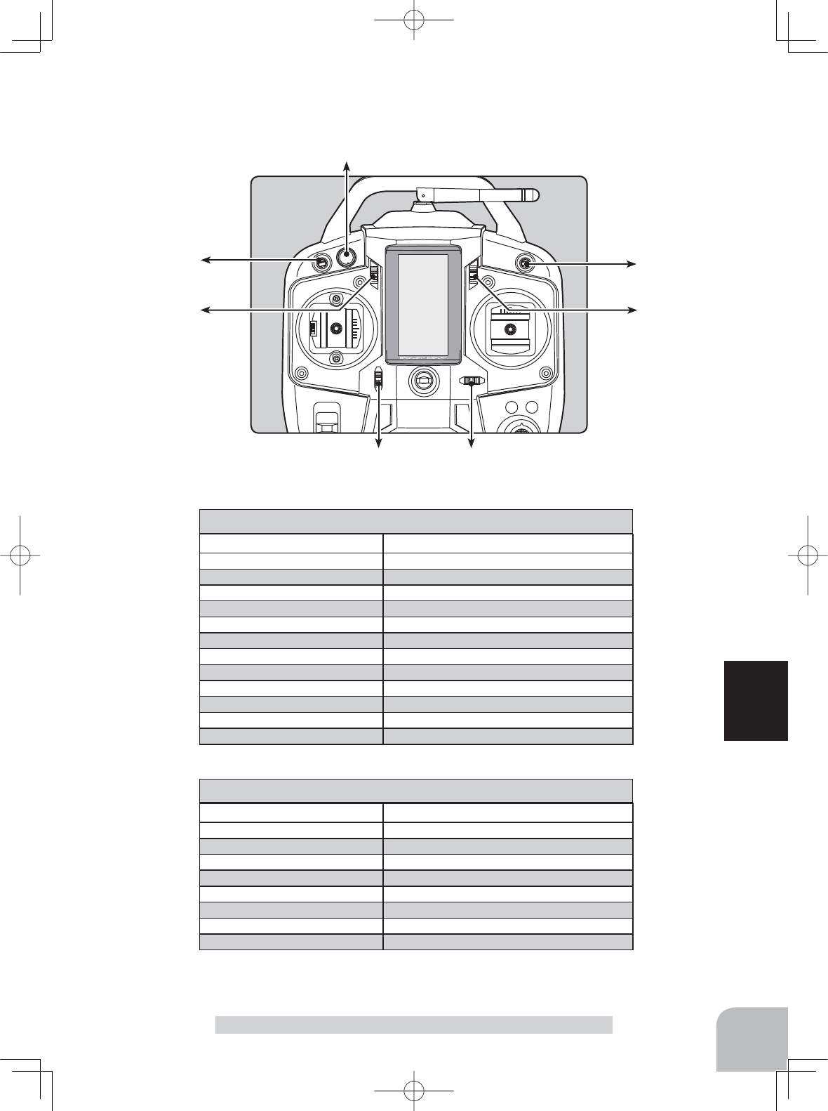
Function Select Trim Dial "TRIM DIAL"
SW1
SW2
DT2 DT1
DT3
DT4
DL1
Abbreviation used on setup screen
Function name, etc.
NT-BRK Neutral brake function ON/OFF
ABS A.B.S function ON/OFF
IDLE Idle up function ON/OFF
PRGMIX Program mixing function ON/OFF
TH-OFF Throttle off (engine cut) function ON/OFF
CH3 Channel 3
CH4 Channel 4
4WS MIX 4WS mixing type select
TIMER Timer function start/stop
LOGGER Telemetry log start/stop
GYRO Switching GYRO mode
OFF Not used
Set table functions (SW1)
Abbreviation used on setup screen
Function name, etc.
NT-BRK Neutral brake function ON/OFF
ABS A.B.S function ON/OFF
IDLE Idle up function ON/OFF
PRGMIX Program mixing function ON/OFF
TH-OFF Throttle off (engine cut) function ON/OFF
CH3 Channel 3
CH4 Channel 4
OFF Not used
Set table functions (SW2)
Pres
s
Pres
s
Pres
s
Pres
s
Select
"BRAKE MIX"
(HOME screen) (MENU 1 screen) (
BRAKE MIX
screen)
(MENU 2 screen)
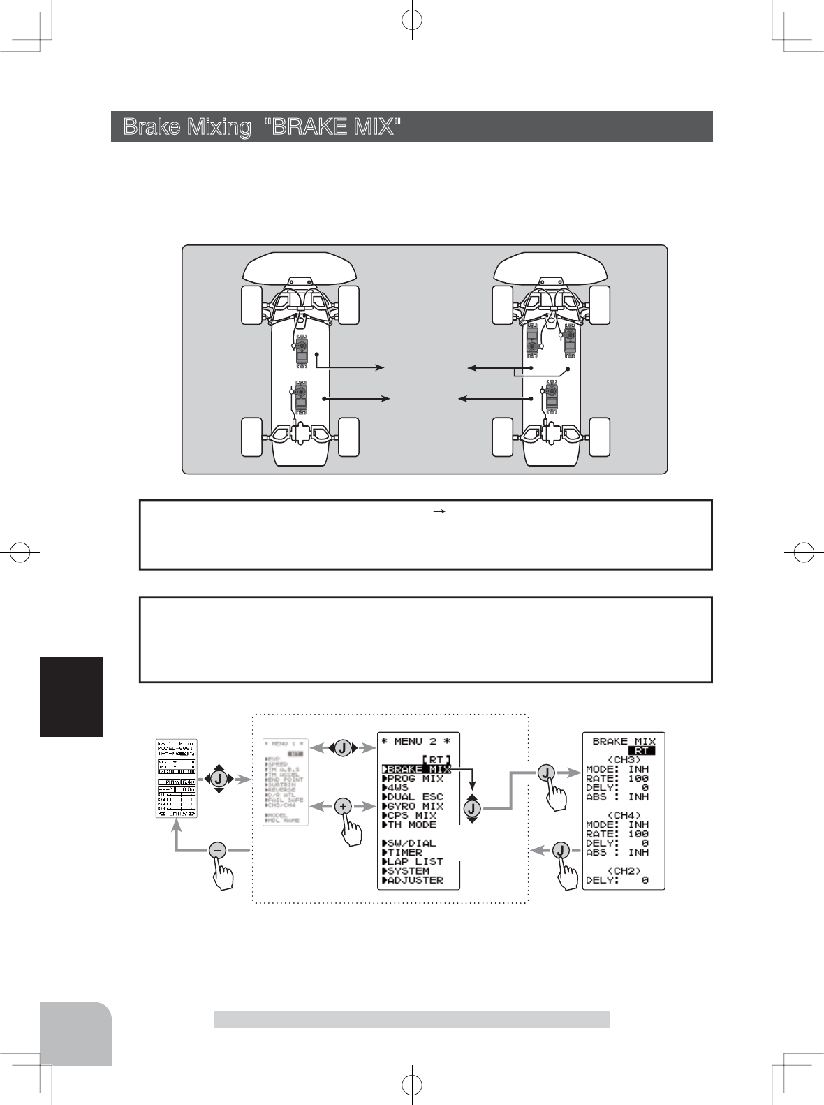
Setup item
<CH3>
MODE : Brake function ON/OFF
RATE : Brake rate
DELY : Delay amount
ABS : ABS. function ON/OFF
<CH4>
MODE : Brake function ON/OFF
RATE : Brake rate
DELY : Delay amount
ABS : ABS. function ON/OFF
<CH2>
DELY : Delay amount
76
Function
Brake Mixing "BRAKE MIX" (Throttle, 3rd /4th channel system)
This function is used when the front and rear brakes must be adjusted independently
such as with a 1/5 scale GP car. This mixing uses the 2nd CH for the rear brakes and
the 3rd or 4th CH for the front brakes, or controls the front brakes with the 3rd CH and
4th CH servos, or controls the 2nd CH by independent throttle and controls the rear and
front brakes with the 3rd CH and 4th CH.
-When braking, mixing is applied to 2nd CH 3rd CH, 4th CH.
-3rd CH and 4th CH brake amount, 2nd CH, 3rd CH, and 4th CH brake delay, and 3rd
CH and 4th CH brake ABS can be set.
Operation
The ABS function can be used independently at the CH3 and CH4 sides even when the
CH2 side ABS function is OFF. The amount of pulsing speed (CYCL), operation point
(TG.P), and duty ratio (DUTY) can be set in common with the CH2 side ABS func-
WLRQ&+DQG&+EUDNHUHWXUQ$%3LV¿[HGDW
CH3/4 brake ABS function
3CH
3CH 4CH
2CH
2CH
or
4CH
Front Brake
Rear Brake
Brake Mixing "BRAKE"
Display "SW/DIAL" screen by the following method:
*This function is not available in "TH-STK : F10 mode".
77
Function
Brake Mixing "BRAKE"
1 (Brake mixing function ON/OFF)
Using the (JOG) button, select "MODE" of <CH3> for CH3
brake and "MODE" of <CH4> for CH 4 brake.
Use the (+) or (-) button and set the function to the "ACT"
state.
"INH" : Function OFF
"ACT" : Function ON
- When "(4WS>OFF)" is displayed below <CH3> ABS, the CH3 brake can-
not be used if the 4WS function is not set to "ACT".
- When "(ESC>INH)" is displayed under <CH4> ABS, the CH4 brake cannot
be used if the dual ESC function is not set to "INH".
2(Brake rate)
Using the (JOG) button, select "RATE" of <CH3> for CH3
brake and "RATE" of <CH4> for CH 4 brake , and use the (+)
and (-) buttons to adjust the Brake rate amount.
3(Delay amount setup)
Using the (JOG) button, select "DELY" of <CH3> for CH3
brake, "DELY" of <CH4> for CH 4 brake and "DELY" of
<CH2> for CH 2 brake. Use the (+) and (-) buttons to adjust
the delay amount.
"0" : No delay
"100" : Maximum delay amount
4(3rd & 4th channels brake-A.B.S ON/OFF)
Using the (JOG) button, select "ABS" of <CH3> for CH3
brake and "ABS" of <CH4> for CH 4 brake. Use the (+) or (-)
button and set the function to the "ACT" state.
5When completed, return to the MENU2 screen by pressing
the (JOG) button.
Brake mixing adjustment
Adjustment buttons
- Use the (+) and (-) buttons to
make adjustments.
- Return to the initial value by
pressing the (+) and (-) but-
tons simultaneously for about
1 second.
Brake rate (RATE)
0 ~ 100
Initial value:100
Delay amount (DELY)
(CH3) 0 ~ 100
(CH4) 0 ~ 100
(CH2) 0 ~ 100
Initial value:0
Function ON/OFF (MODE)
INH, ACT
Function ON/OFF (ABS)
INH, ACT
The function select
switch dial
function can control the 3rd/4th channels. Brake rate
(RATE) can be controlled with digital dial or digital trim, using the function select dial
function.
Dial / Trim Setting
To use CH3 of the brake mixing function, 4WS mixing must be set to "INH".
To use CH4 of the dual ESC function and CPS mixing must be set to "INH".
Setting the 4WS mixing / dual ESC function
Select button
- Select with the (+) or (-) but-
tons.
Select button
- Select with the (+) or (-) but-
tons.
Pres
s
Pres
s
Pres
s
(HOME screen) (MENU 1 screen) (PROG MIX screen)
(MENU 2 screen)
Pres
s
Select
"
PROG MIX
"
78
Function
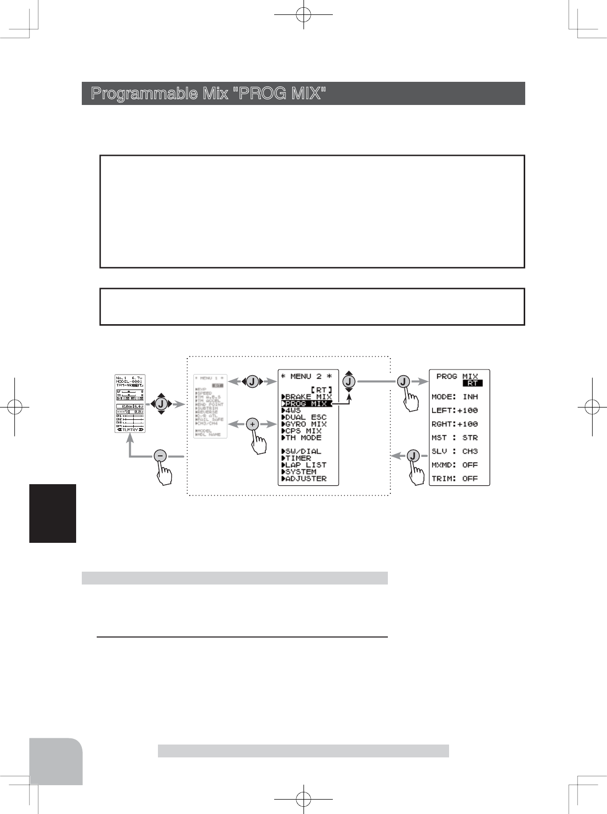
Programmable Mix "PROG MIX"
This function allows you to apply mixing between the steering, throttle, channel 3 and
channel 4.
-When the steering or throttle channel is the master channel (channel that applies mix-
ing), trim data can be added. (Trim mode)
- The mixing mode selection. (Master mixing mode)
Relating function
steering :EPA, STR EXP, D/R, SPEED, 4WS
throttle :EPA, THR EXP, ATL, ABS, SPEED, BRAKE MIX, NT-BRK, ESC MIX, TH ACCEL
CH3 :EPA,BRAKE MIX,4WS
CH4 :EPA,BRAKE MIX,ESC MIX
Additional Functions
The movement of the slave channel will be in proportion to the movement of the master
channel.
Movement of the slave channel side
Programmable Mix "PROG MIX" (All channels)
Function SW
PROGMIX
Program mixing adjustment
(Preparation)
- When "PROG MIX" is turned ON and OFF by switch, set
the switch by select switch dial function.
1 (Mixing function ON/OFF)
Select the setting item "MODE" using the (JOG) button up or
down operation. Use the (+) or (-) and set the function to the
"ON" or "OFF" state.
“INH” : Function OFF
“ON” : Function ON. When the switch is OFF, “OFF” is displayed.
Display "PROG MIX" screen by the following method:
Function ON/OFF (MODE)
INH,ON(OFF)
Setup items
MODE : Function ON/OFF
LEFT :
Mixing rate (Left side)
RGHT :
Mixing rate (Right side)
MST : Master channel
SLV : Slave channel
MXMD : Mix mode
TRIM : Trim mode
Select button
- Select with the (+) or (-) but-
tons.
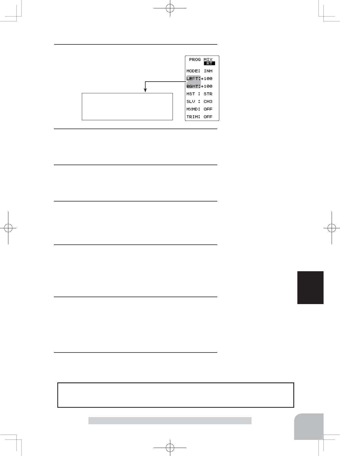
These setup items are different dep-
completed on the master channel.
Upper side : LEFT/FWRD/UP
Lower side : RGHT/BRAK/DOWN
Program mixing function
79
Function
Programmable Mix "PROG MIX"
Mixing amount
-120~0~+120
Initial value: +100
Channel selection (MST)
STR, THR, CH3, CH4
Initial value :STR
Channel selection (SLV)
STR, THR, CH3, CH4
Initial value :CH3
Mixing mode (MXD)
OFF, ON
Initial value: OFF
Mixing amount
-120~0~+120
Initial value: +100
Trim mode (TRIM)
OFF, ON
Initial value: OFF
2(Master channel)
Select setup item "MST" using the (JOG) but-
ton up or down operation, and select the mas-
ter channel by pressing the (+) or (-) button.
Select the program mixing function ON/OFF switch with the function select switch
dial function. Mixing rate (RATE) can be controlled with digital dial or digital trim,
using the function select switch dial function.
Switch / Dial / Trim Setting
3(Slave channel)
Select setup item "SLV" using the (JOG) button up or down
operation, and select the slave channel by pressing the (+)
or (-) button.
4 (Left, forward or up side mixing amount adjustment)
Select the setting item "LEFT", "FWRD", or "UP" using the
(JOG) button up or down operation. Use the (+) or (-) button
and adjust the left, forward, or up side mixing amount.
5 (Right, brake or down side mixing amount adjustment)
Select the setting item "RGHT", "BRAK", or "DOWN" using
the (JOG) button up or down operation. Use the (+) or (-) but-
ton and adjust the right, brake, or down side mixing amount.
6(Mixing mode setup)
Select setup item "MXMD" using the (JOG) button up or
down operation, and use the (+) or (-) button to select the
mixing mode.
"OFF" :Mixing proportional to master channel operation.
"MIX" :Mixing by master channel another function considered.
7(Trim mode setup)
Select setup item "TRIM" using the (JOG) button up or down
operation, and use the (+) or (-) button to select the mixing
mode.
"OFF" :Trim is removed.
"ON" :Trim is added.
8When completed, return to the MENU2 screen by pressing
the (JOG) button.
Adjust button
- Use the (+) and (-) buttons to
make adjustments.
- Return to the initial value
"100" by pressing the (+) and
(-) buttons simultaneously for
about 1 second.
Select button
- Select with the (+) or (-) but-
tons.
Select button
- Select with the (+) or (-) but-
tons.
Select button
- Select with the (+) or (-) but-
tons.
Select button
- Select with the (+) or (-) but-
tons.
*This function is not available in "TH-STK : F10 mode".
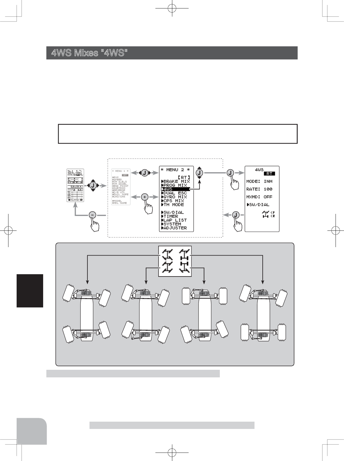
Front axle only
(4WS OFF)
Same steer Reverse steer Rear axle only
Pres
s
Pres
s
Pres
s
(HOME screen) (MENU 1 screen) (4WS screen)
(MENU 2 screen)
Pres
s
Select
"
4WS
"
80
Function
This function can be used with crawlers and other 4WS type vehicles. It is mixing which
uses the 1st CH to control the front axle steering and the 3rd CH to control the rear axle
steering.
OFF (front axle only), reverse steer, same steer, rear axle only and other 4WS type
switching is used by selecting SW1 with the function select switch function. If not se-
lected, <NO SW> is displayed. Therefore, select SW1.
4WS Mixes "4WS" (Steering, 3rd channel system)
Setup items
MODE :4WS Type
RATE :
3ch rate (Rear side)
MXMD :Mix mode
4WS Mixes “4WS”
(Preparation)
Since this function is used by switching the type of 4WS with
a switch, the switch used by the function select switch dial
function is set.
4WS mixing adjustment
When the 3rd CH was set to ACT at Brake Mixing or when Gyro Mixing is used, 4WS
mixing cannot be used.
Setting Special mixings
Display "4WS" screen by the following method:
Function SW
4WS
The function select switch
screen can be displayed
from this screen.
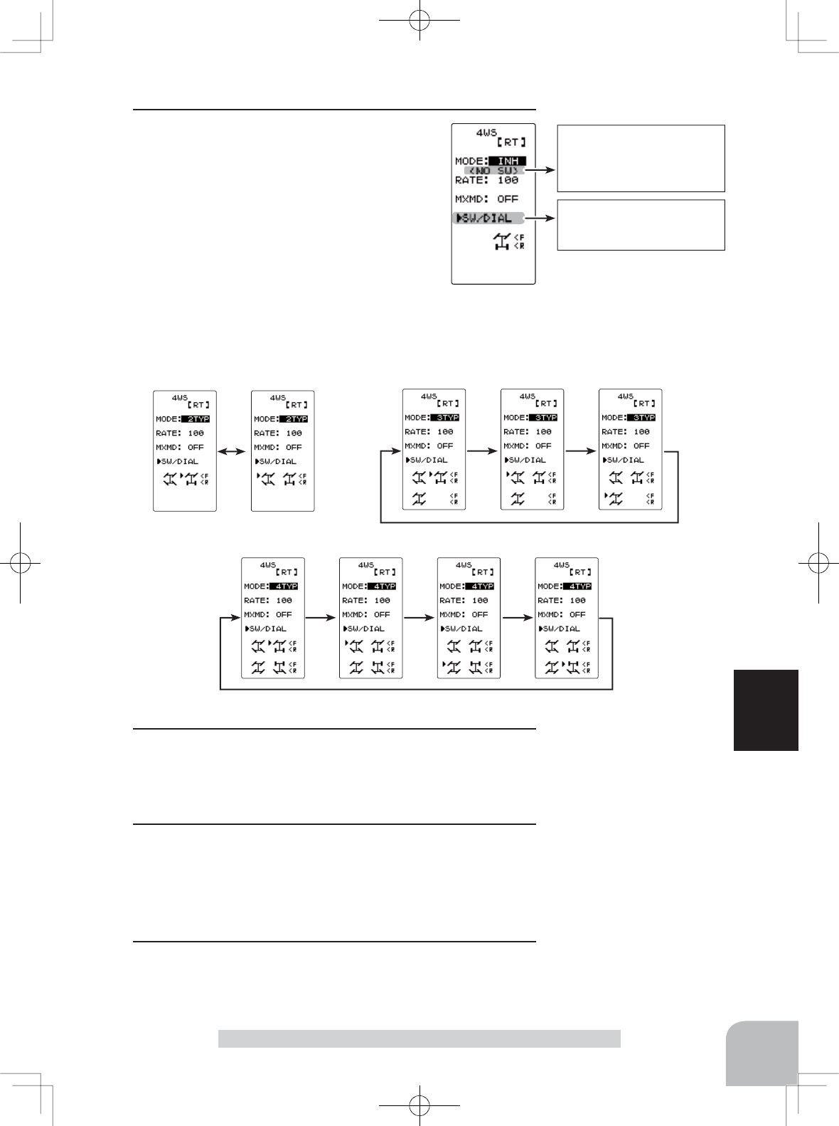
< NO SW >
If function’s ON/OFF
switch is not selected,
<NO SW> is displayed.
81
Function
4WS Mixes “4WS”
1(4WS type selection)
Select the setting item "MODE" using the
(JOG) button up or down operation. Use the
(+) or (-) and set the function to the "ON" or
"OFF" state.
"INH" :Function OFF (front only)
"2TYP" :Front axle only, reverse steer switching
"3TYP" :Front axle only, reverse steer and same steer switching
"4TYP" :Front axle only, reverse steer, same steer, and rear steer only switching
Switched in the order shown in the figure below by set SW
Function ON/OFF (MODE)
OFF, 2TYP, 3TYP, 4TYP
Mixing mode (MXMD)
OFF, ON
Initial value: OFF
Rear rate (RATE)
0 ~ 100
Initial value:100
"2TYP":Front axle only and reverse
steer switching "3TYP":Front axle only, reverse steer, and same steer switching
"4TYP":Front axle only, reverse steer, same steer, and rear axle only switching
Adjustment buttons
- Use the (+) and (-) buttons to
make adjustments.
- Return to the initial value by
pressing the (+) and (-) but-
tons simultaneously (approx.
1 sec).
2(Rear side travel adjustment)
Select setting item "RATE" using the (JOG) button up or
down operation. Adjust the rear axle travel with the (+) or (-)
button.
3(Mix mode setting)
Select setting item "MXMD" using the (JOG) button up or
down operation. Set the mix mode with the (+) or (-) button.
"OFF" :The EXP function of the 1st CH and other settings are not mixed.
"ON" :The EXP function of the 1st CH and other settings are mixed.
4When completed, return to the MENU screen by moving the
cursor to the positions other than SW/DIAL and pressing the
(JOG) button.
Select button
- Select with the (+) or (-) but-
tons.
Select button
- Select with the (+) or (-) but-
tons.
Pres
s
Pres
s
Pres
s
(HOME screen) (MENU 1 screen) (DUAL ESC screen)
(MENU 2 screen)
Pres
s
Select
"
DUAL ESC
"
The function select switch
screen can be displayed
from this screen.
82
Function
Dual ESC mixing "DUAL ESC"
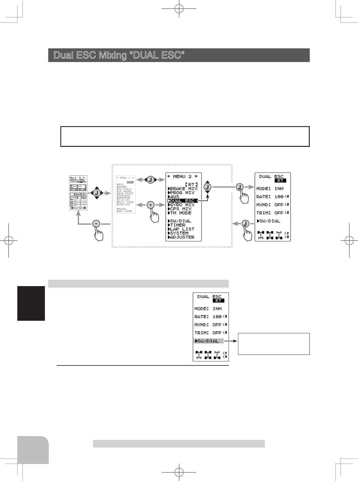
This function is mixing used with crawlers and other 4WD type vehicles and uses the
2nd CH to control the front motor controller and the 4th CH to control the rear motor
controller.
Front drive only, rear drive only, or both front and rear drive can be selected using any
programmed DT (digital trim) button.
Dual ESC Mixing "DUAL ESC" (Throttle system)
(Preparation)
- This function is used to switch between front
drive/4WD/rear drive using one of the dials
(trim). Set the desired dial (trim) for this func-
tion using the SW/DIAL screen.
1 (Dual ESC setting)
Select the setting item "MODE" using the (JOG) button up
or down operation. Set the function by pressing the (+) or (-)
button.
"INH" : Function OFF
"ACT" : Function ON
Dual ESC mixing adjustment
Function ON/OFF (MODE)
INH, ACT
Display "DUAL ESC" function screen by the following method:.
When the 4th CH was set to ACT at Brake Mixing or when CPS Mixing is used, Dual
ESC mixing cannot be used.
Setting Special mixings
Setup items
MODE : Function ON/OFF
RATE :
4ch rate (Rear side)
MXMD : Mix mode
TRIM : Trim mode
Function SW
ESC-MD
Select button
- Select with the (+) or (-) but-
tons.
83
Function
Dual ESC mixing "DUAL ESC"
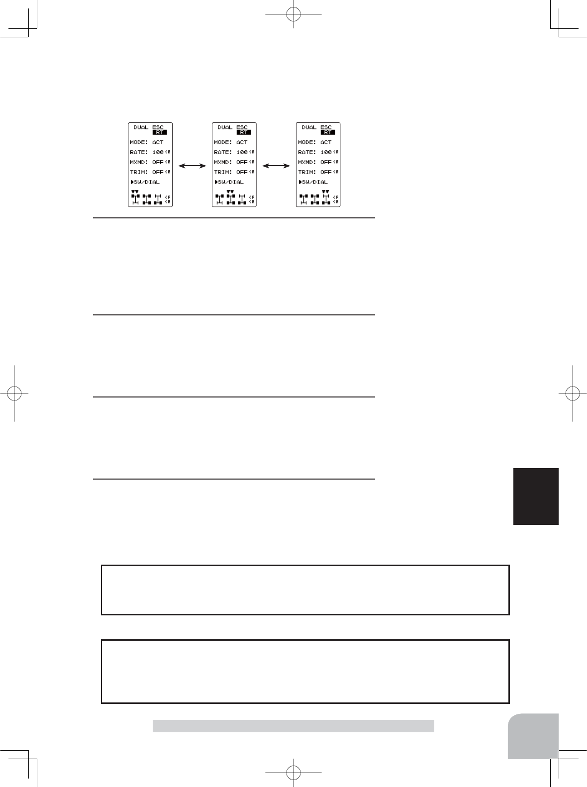
The programmed DT button is used to select the drive type
as shown in the figure below.
The function select dial function can control the 4th channel’s ESC (Rear drive) rate
(RATE) with digital dial or digital trim, using the function select switch dial function.
Dial / Trim Setting
As this function drives 2 separate motor controllers simultaneously, a mutual load is
applied. Use this function carefully so that the motor controllers are not damaged. Fu-
taba will not be responsible for motor controller, motor, and other vehicle trouble due
to use of this function.
Note:
Rear rate (RATE)
0 ~ 120
Initial value:100
Adjustment buttons
- Use the (+) and (-) buttons to
make adjustments.
- Return to the initial value by
pressing the (+) and (-) but-
tons simultaneously (approx.
1 sec).
Mixing mode (MXMD)
OFF, ON
Initial value: OFF
Trim mode (TRIM)
OFF, ON
Initial value: OFF
2 (Rear drive travel adjustment)
Select the setting item "RATE" by the (JOG) button up or
down operation. Use when applying a rotation difference to
the front and rear wheels by adjusting the rear (CH4) motor
controller travel with the (+) or (-) button.
3 (Mix mode setting)
Select the setting item "MXMD" by the (JOG) button up or
down operation. Set the mix mode with the (+) or (-) button.
"OFF" : CH2 EXP function and other settings are not mixed.
"ON" : CH2 EXP function and other settings are mixed.
4 (Trim mode setting)
Select the setting item "TRIM" by the (JOG) button up or
down operation. Set the trim mode with the (+) or (-) button.
"OFF" : Front drive (CH2) trim data is not included.
"ON" : Front drive (CH2) trim data is included.
5When completed, return to the MENU screen by moving the
cursor to the positions other than SW/DIAL and pressing the
(JOG) button.
Select button
- Select with the (+) or (-) but-
tons.
Select button
- Select with the (+) or (-) but-
tons.
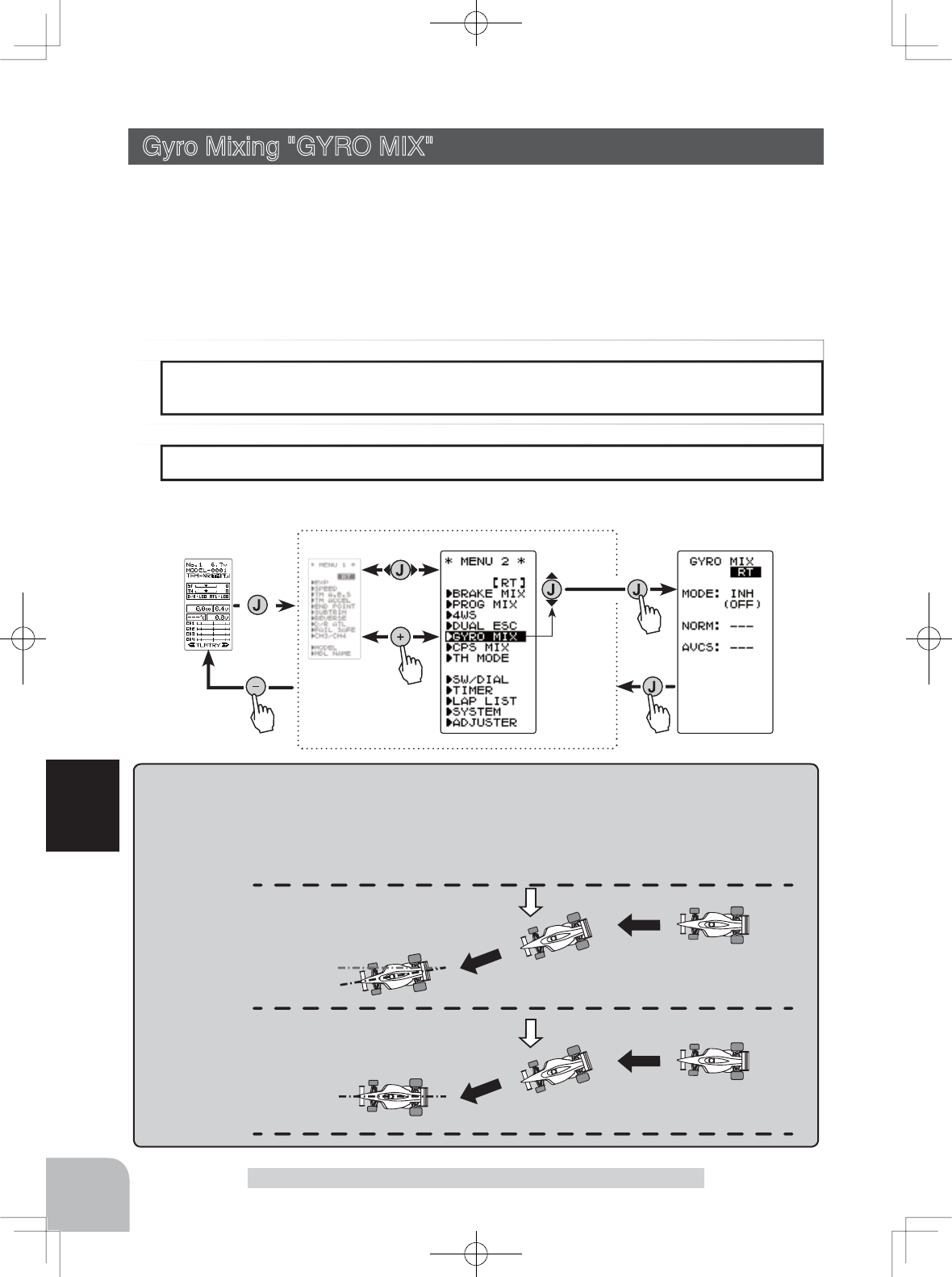
AVCS / NORMAL Modes
The gyro has 2 operating modes: NORMAL mode and AVCS mode. In the AVCS mode, the angle is con-
trolled simultaneously with NORMAL mode rate control (swing speed). The AVCS mode increases straight
running stability more than that of the NORMAL mode. Because the feel of operation is different, choose your
favorite mode.
NORMAL
Countersteers against out-
side force, but cannot cor-
rect the skid direction.
AVCS
Corrects the skidding direc-
tion and forcefully main-
tains the heading.
Outside
force
Outside
force
Pres
s
Pres
s
Pres
s
(HOME screen) (MENU 1 screen) (GYRO MIX screen)
(MENU 2 screen)
Pres
s
Select
"
GYRO MIX
"
84
Function
This function is a remote gain function which adjusts the sensitivity of the Futaba car
rate gyro at the T4GRS side, and is mixing that uses the 3rd CH to adjust the gyro sensi-
tivity.
When using the T4GRS and switching between AVCS and NORMAL modes use SW1
with the function select switch function.
For a description of the car rate gyro mounting method and handling, refer to the rate
gyro instruction manual.
Gyro Mixing "GYRO MIX" (Steering system)
When the 3rd CH was set to ACT at Brake Mixing or when 4WS Mixing is used, Gyro
mixing cannot be used.
Setting Special mixings
The gain amount can be adjusted by using the function switch dial function.
Dial / Trim Setting
Display "GYRO MIX" screen by the following method:
Gyro mixing "GYRO MIX"
The function select switch
screen can be displayed
from this screen.
85
Function
Gyro mixing "GYRO MIX"
(Preparation)
- Refer to the gyro instruction manual and connect the gyro
to the receiver. When using remote gain, connect gyro sensi-
tivity adjustment to the 3rd CH of the receiver.
- When using gyro mixing by switching between the NORM
(normal) and AVCS modes, use the function select switch di-
al function to set the switch to be used.
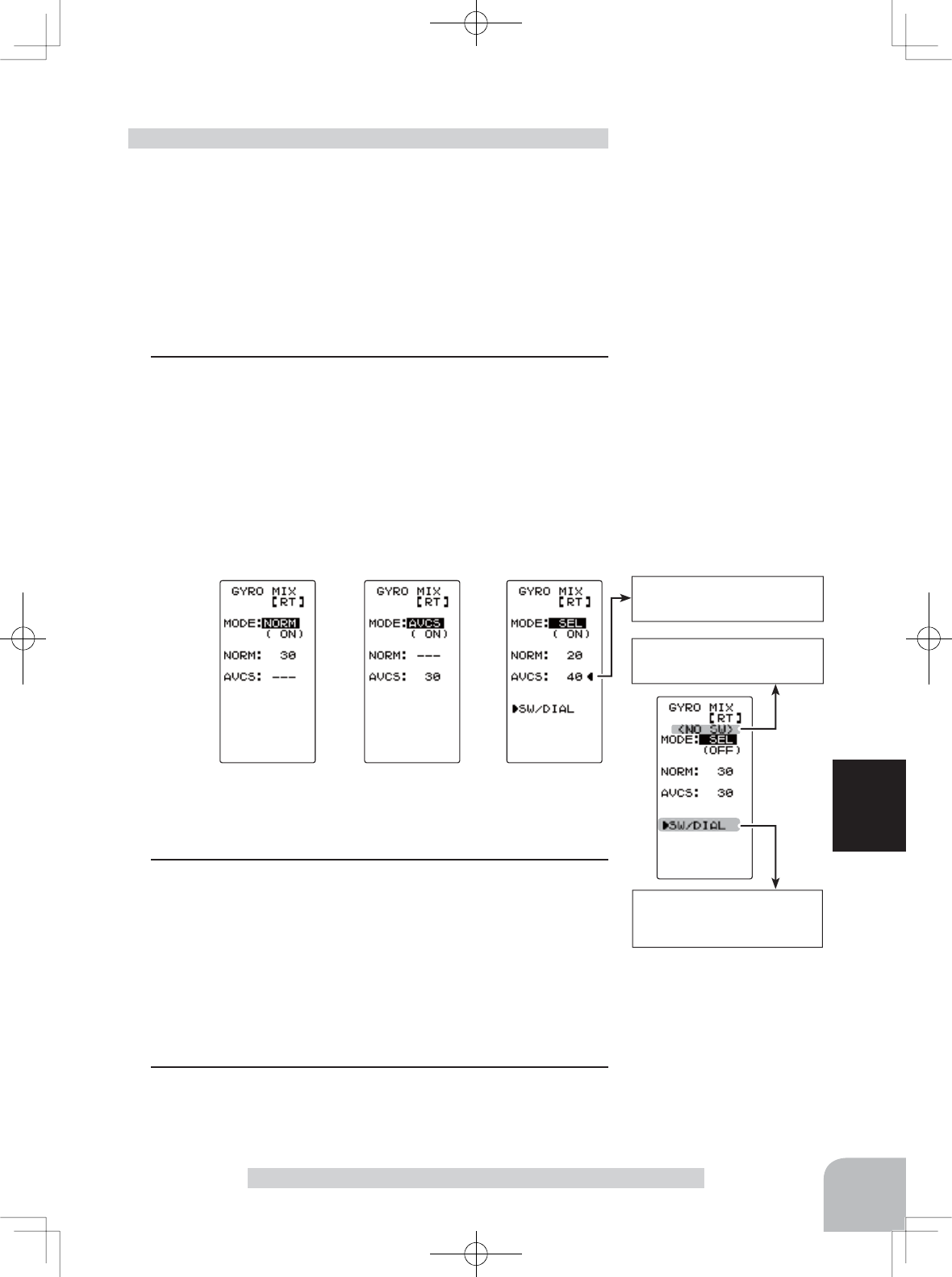
1 (Gyro mixing setting)
Select the setting item "MODE" using the (JOG) button up
or down operation. Set the function by pressing the (+) or (-)
button.
"INH" : Function OFF
"NORM" :NORMAL mode gain
"AVCS" :AVCS mode gain
"SEL" :Switching Normal mode and AVCS mode
(Displayed <NO SW> when the Gyro Mode SW is not used.)
Gyro mixing adjustment
2(NORMAL gain adjustment)
Select the setting item "NORM" using the (JOG) button up or
down operation. Adjust the NORMAL gain with the (+) or (-)
button.
(AVCS gain adjustment)
Select the setting item "AVCS" using the (JOG) button up
or down operation. Adjust the AVCS gain with the (+) or (-)
button.
3When completed, return to the MENU screen by moving the
cursor to the positions other than SW/DIAL and pressing the
(JOG) button.
Function selection (MODE)
INH, NORM, AVCS, SEL
NORMAL / AVCS gain
(NORM / AVCS)
0 ~ 120
Initial value:30
Displayed when the Gyro
Mode SW is not used.
"NORM" mode "AVCS" mode
Shows the gyro mode se-
lect switch mode.
"SELE" mode
Function SW
GYRO
SW type
ALT
Adjustment buttons
- Use the (+) and (-) buttons to
make adjustments.
- Return to the initial value by
pressing the (+) and (-) but-
tons simultaneously for about
1 second.
Select button
- Select with the (+) or (-) but-
tons.
Setup items
MODE : Gyro mode
NORM :
Normal mode gain
AVCS :
AVCS mode gain