Contents
- 1. User Manual Part 1
- 2. User Manual Part 2
- 3. User Manual Part 3
User Manual Part 3
Pres
s
Pres
s
Pres
s
(HOME screen) (MENU 1 screen) (CPS MIX screen)
(MENU 2 screen)
Pres
s
Select
"
CPS MIX
"
86
Function
Gyro mixing "CPS MIX"
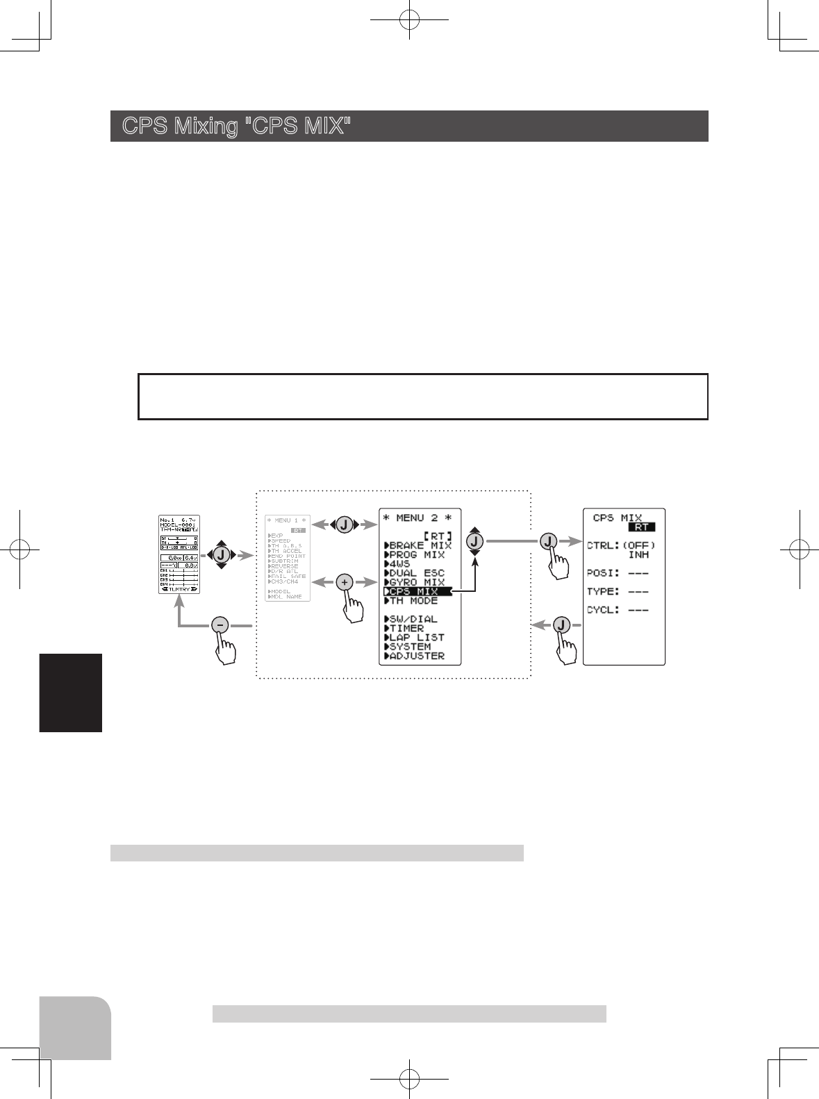
Display "CPS MIX" screen by the following method:
This function controls the Futaba CPS-1 channel power switch.
Normally, when using the CPS-1 unit to power the vehicle lights etc (LED) the CPS-
1 unit with LED connected is connected to a vacant switch channel and the LEDs are
turned on and off by the switch while the vehicle is running. However, when the CPS-
1 mixing (CPS MIX) function is used, the LED can be turned on and off and ashed in
step with steering and throttle operation, as well as being turned on and off by switch.
The ashing speed (cycle) can also be set.
For instance, the LED can be ashed as a brake light when the brakes are operated.
CPS Mixing "CPS MIX"
When the 4th CH was set to ACT at Brake Mixing or when Dual ESC Mixing is used,
CPS mixing cannot be used.
Setting Special mixings
(Preparation)
- Connect the CPS-1 to the 4th CH of the receiver.
- When the LEDs are turned on and off by switch, use the
function select switch dial function to set the switch to be
used.
CPS mixing adjustment
Function SW
CH4
Setup items
MODE : Function ON/OFF, control mode
POSI :
ON/OFF position
TYPE :
ON/OFF type
TCYCL : Flashing speed
ON/OFF Position (POSI)
5 ~ 95
Initial value: 50
Shows the ON/OFF state
87
Function
Gyro mixing "CPS MIX"
1 (Control system setup)
Operate the (JOG) button up and down and select the setting
item "CTRL". Use the (+) or (-) button and select the function.
"INH" : Function OFF
"CH4 FUNC" : ON/OFF by switch set at the 4th CH
"STR NT" : ON at steering neutral
"STR END" : ON at both sides of steering
"THR NT" : ON at throttle neutral
"THR FWD" : ON at throttle forward side
"THR BRK" : ON at throttle back (brake) side
"TH NT+BK" : ON at throttle neutral and back (brake) sides
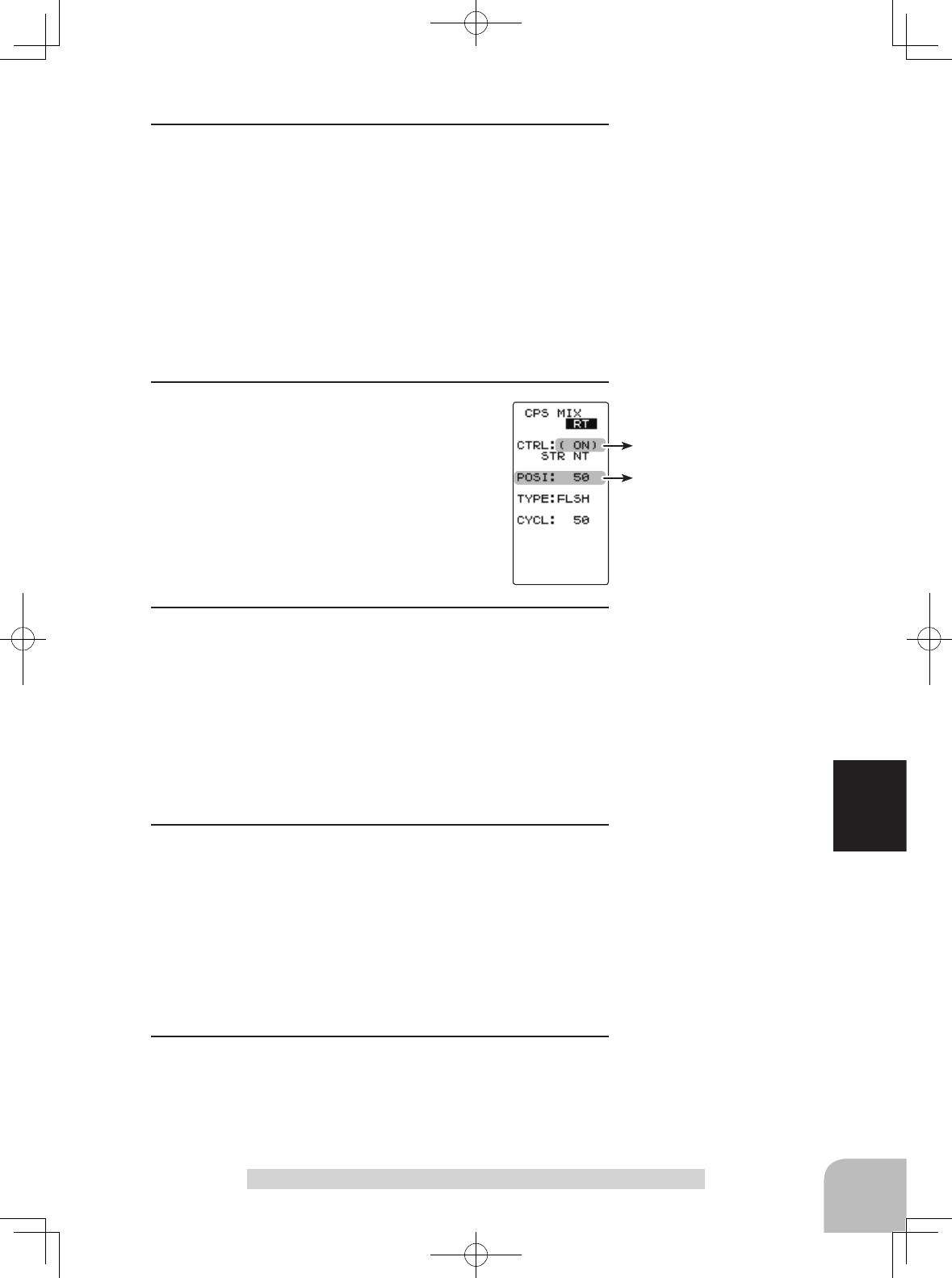
2 (ON/OFF switching position selection)
Select the setting item "POSI" using the (JOG)
button up or down operation. Use the (+) or (-)
button and select the ON/OFF position. Since
the ON/OFF state is displayed at the right
side of the setting item "CTRL", setting can be
confirmed while operating the function to be
controlled (for example, throttle).
3 (ON/OFF type setup)
Select the setting item "TYPE" using the (JOG) button up or
down operation. Use the (+) or (-) button and select the type
of LED lighting. Normal ON/Off type or flashing can be se-
lected.
"NORMAL" : Normal ON/OFF type
"FLASH" : Flashing display
4 (Flashing cycle setting)
When flashing type "FLASH" was selected at the setting item
"TYPE" the flashing speed (cycle) can be set.
Select the setting item "CYCL" using the (JOG) button up or
down operation. Use the (+) or (-) button and select the flash-
ing speed (cycle).
5When completed, return to the MENU2 screen by pressing
the (JOG) button.
Select button
- Select with the (+) or (-) but-
tons.
Adjust button
- Use the (+) and (-) buttons to
make adjustments.
- Return to the initial value by
pressing the (+) and (-) but-
tons simultaneously for about
1 second.
Select button
- Select with the (+) or (-) but-
tons.
Function selection (MODE)
INH, CH4 FUNC, STR NTR,
STR END, THR NT, THR FWD,
THR BRK, TH NT+BK
Function selection (TYPE)
NORMAL, FLASH
Flashing cycle (CYCL)
1 ~ 100
Initial value:50
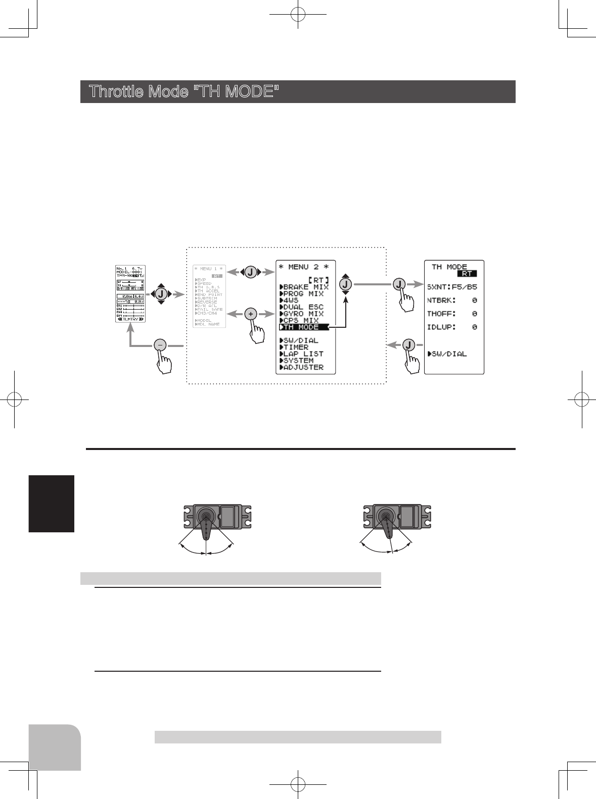
5 : 57 : 3
F5/B5 F7/B3
Forward side Brake side Forward side Brake side
Pres
s
Pres
s
Pres
s
(HOME screen) (MENU 1 screen) (TH MODE screen)
(MENU 2 screen)
Pres
s
Select
"
TH MODE
"
88
Function
Throttle Mode "TH MODE"
This menu has the following 4 functions:
- Servo neutral mode, which sets the throttle neutral ratio to 7:3 or 5:5
- Idle up, which raises the idling speed when starting the engine to improve engine start-
ing performance of a gasoline car (boat)
- Neutral brake, which applies the brakes at the neutral position of the throttle stick
- Throttle off (engine cut), which stops the engine of a boat, etc. by operating the throttle
servo to the low side regardless of the position of the throttle stick.
Throttle servo neutral position "SXNT"
-This function allows selection of the forward side and brake (reverse) side operation ra-
tio from 7:3 or 5:5 by changing the neutral position of the throttle servo.
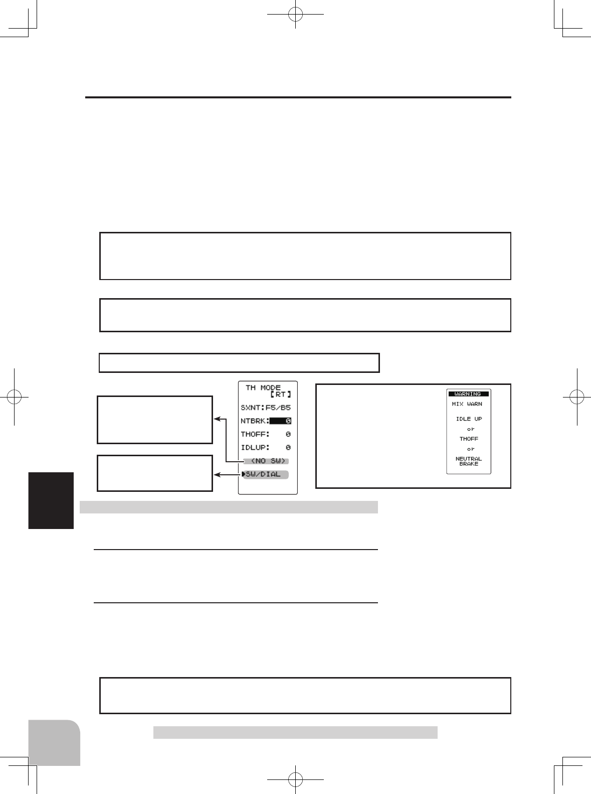
Throttle Mode "TH MODE" (Throttle system)
1 (Mode selection)
Select the setting item "SXNT" by (JOG) button. Select "F5/
B5" or "F7/B3" by (+) or (-) button.
"F5/B5" =Forward 50% : Back50%
"F7/B3" =Forward 70% : Back30%
2When completed, return to the MENU screen by moving the
cursor to the positions other than SW/DIAL and pressing the
(JOG) button.
Selecting the throttle servo neutral position
Mode selection (SXNT)
F5/B5, F7/B3
Display "TH MODE" screen by the following method:
Select button
- Select with the (+) or (-) but-
tons.
Setup items
SXNT :Throttle servo neutral position
IDLUP :Idle-Up rate
NTBRK :Neutral brake rate
THOFF :Throttle off (engine cut) position
*This function is not available in "TH-STK : F10 mode".
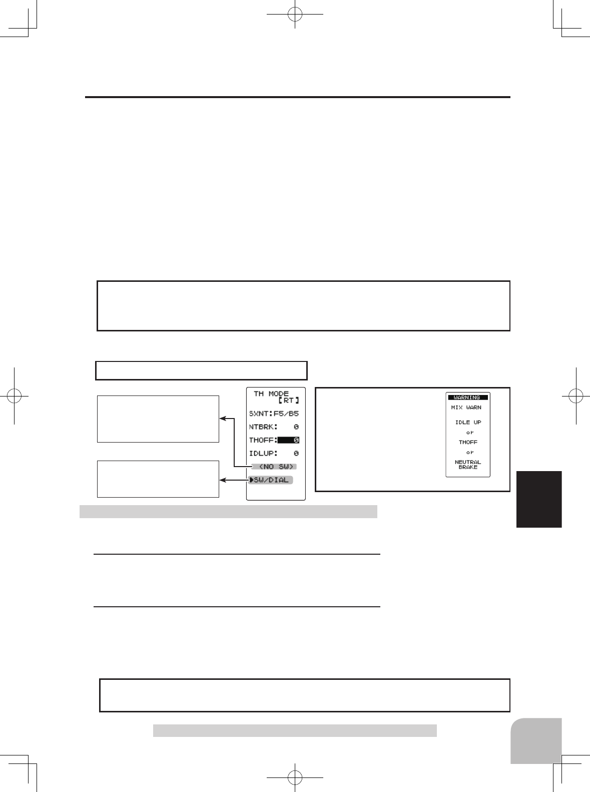
Warning display
The function select switch
dial screen can be dis-
played from this screen.
< NO SW >
If function’s ON/OFF switch
is not selected, <NO SW>
is displayed.
89
Function
Throttle Mode "TH MODE"
Idle-Up "IDLUP"
This is a function select switch dial function. The idle up switch must be set.
This function is used to improve engine starting performance by raising the idling speed
when starting the engine of a gasoline car (boat). It is also effective when you want to
eliminate any braking effect when the power is turned off during running, due to the
effect of your gear ratio setting and choice of motor when operating an electric car.
However, considering safety, and to prevent the motor from rotating instantly when the
power was turned on, the MC950CR, MC851C, MC602C, MC402CR, and other Futaba
MC (Motor Controllers) will not enter the operation mode if the neutral position is not
conrmed. When using the MC950CR, MC851C, MC602C, MC402CR, or other Futaba
MC, conrm that the MC is in the neutral position and the set is in the operation mode
before setting the idle up function switch to ON.
The throttle neutral position is offset to the forward side. There is no linkage locking,
etc. because there is no change near the maximum operation angle even when the neu-
tral position is offset by this function.
Operation
(Preparation)
- Use the function select switch dial to select the switch.
1(Idle-Up rate)
Select the setting item "IDLUP" using the (JOG) button. Use
the (+) and (-) buttons to set the Idle-Up rate.
2When completed, return to the MENU screen by moving the
cursor to the positions other than SW/DIAL and pressing the
(JOG) button
Idle-Up function adjustment Adjust button
- Adjust with the (+) and (-) but-
tons.
- Return to the initial value "0" by
pressing the (+) and (-) buttons
simultaneously for about 1 sec-
ond.
Idle-Up rate (IDLUP)
D50 ~ D1, 0, U1 ~ U50
Initial value: 0
"D": Brake side
"U": Forward side
If the power switch is
turned on while the
idle-up switch is on, an
audible alarm will be
heard. Immediately set
the Idle-Up switch to
OFF.
While this function is ON, the LED blinks.
Operation Display
The function select dial function can control the Idle-up rate with digital dial or digital
trim.
Dial / Trim Setting
Warning display
The function select switch
screen can be displayed
from this screen.
< NO SW >
If function’s ON/OFF
switch is not selected,
<NO SW> is displayed.
90
Function
(Preparation)
- Use the function select switch dial to select the switch.
1(Neutral brake rate)
Select the setting item "NTBRK" using the (JOG) button. Use
the (+) and (-) buttons to set the neutral brake rate.
2When completed, return to the MENU screen by moving the
cursor to the positions other than SW/DIAL and pressing the
(JOG) button
Neutral Brake function adjustment
The ESC neutral brake function and T4GRS neutral brake function can be used simul-
taneously. However, when setting is difcult to understand, we recommend that only
one neutral brake function be used.
Reference
Throttle Mode "TH MODE"
When the neutral brake function is
"
ON
"
, the
neutral
brake rate adjustment is auto-
matically assigned to the throttle trim (DT1/2/3/4 or DL1).
Dial / Trim Setting
Throttle side EPA function, or ATL function setting, also affects neutral brake side
operation.
Effect of set value of other functions on neutral brake
Neutral Brake "NTBRK"
This is a function select switch dial function. The neutral brake function ON/OFF
switch must be set.
The neutral brake, which applies the brakes at the neutral position of the throttle stick,
can be set. However, when using the MC950CR, MC851C, MC602C, MC402CR, or
other Futaba MC (Motor Controller), conrm that the MC is in the neutral position and
the set is in the operation mode before setting the neutral brake function switch to ON,
the same as the idle up function. In addition, when the idle up function or throttle off
function is set, these functions have a higher priority than the neutral brake function.
An LED blinks while the neutral brake function is active.
Operation display
If the power switch is
turned on while the neu-
tral brake switch is on,
an audible alarm will be
heard. Immediately set
the neutral brake switch
to OFF.
Adjust button
- Adjust with the (+) and (-) but-
tons.
- Return to the initial value "0" by
pressing the (+) and (-) buttons
simultaneously for about 1 sec-
ond.
Brake rate (NTBRK)
0 ~ B100
Initial value: 0
*This function is not available in "TH-STK : F10 mode".
Warning display
The function select switch
screen can be displayed
from this screen.
< NO SW >
If function’s ON/OFF
switch is not selected,
<NO SW> is displayed.
91
Function
Throttle Mode "TH MODE"
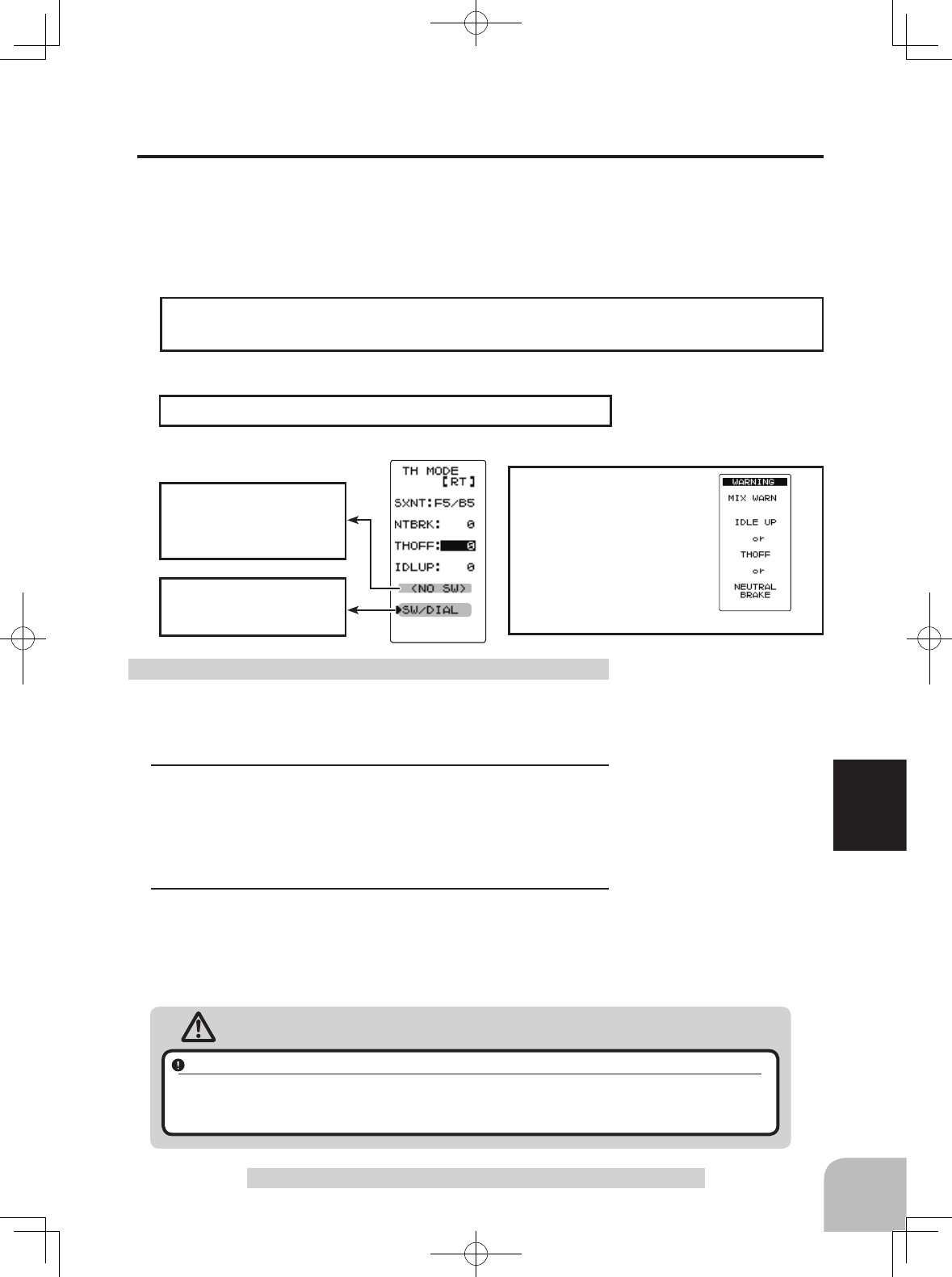
(Preparation)
- Use the function select switch dial to select the switch.
1(Preset position setup)
- Select the setting item "THOFF" using the (JOG) button.
Use the (+) and (-) buttons to set the preset position of the
throttlle servo.
2When completed, return to the MENU screen by moving the
cursor to the positions other than SW/DIAL and pressing the
(JOG) button
Engine Cut function adjustment
Caution
Always check carefully before using this function.
While switch with preset function set is in the ON state, the servo (motor controller) is locked in the preset posi-
tion and does not operate even if the throttle stick is operated. If the servo was operated at the wrong setting,
you may lose control of the car (boat).
Adjust button
- Adjust with the (+) and (-) but-
tons.
- Return to the initial value by
pressing the (+) and (-) buttons
simultaneously (approx. 1 sec).
Preset position (THOFF)
0 ~ B100
Initial value: 0
Throttle Off (engine cut) "THOFF"
This is a function select switch dial function. The throttle off function ON/OFF switch
must be set. The engine cut function stops the engine of a boat, etc. by operating the
throttle servo to the slow side by switch regardless of the position of the throttle stick
and the setting of other functions (reverse function setting is effective).
An LED blinks while the neutral brake function is active.
Operation display
If the power switch is
turned on while the
throttle-off switch is on,
an audible alarm will be
heard. Immediately set
the neutral brake switch
to OFF.
The function select dial function can control the throttle-off position can be controlled
with digital dial or digital trim.
Dial / Trim Setting
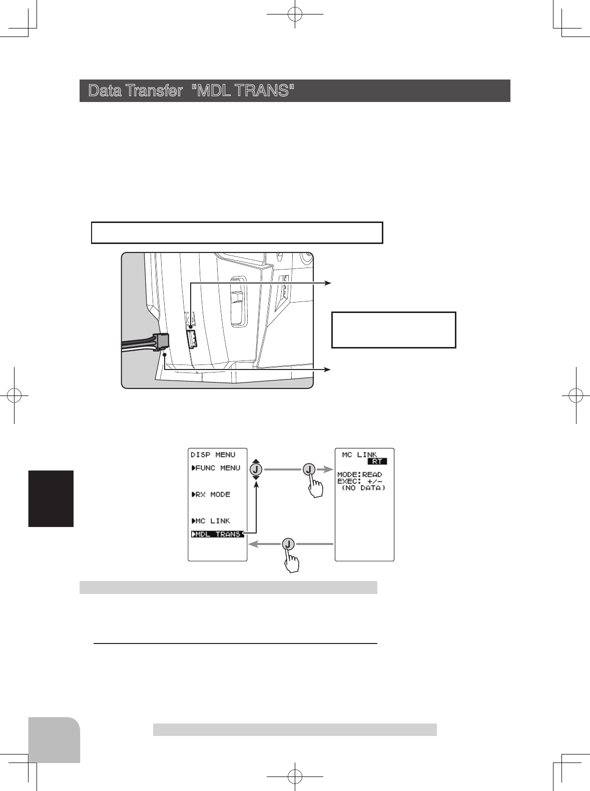
Communication port
ESC receiver connector
Connecting ESC receiver
connector to the transmitter
Communication port
Connection diagram
92
Function
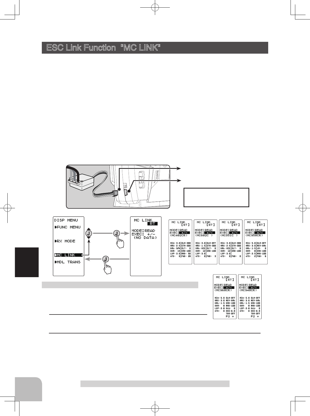
(Preparation)
-Connect the T4GRS and ESC in accordance with the connection
diagram, and connect the battery to ESC.
1Set the transmitter power switch to the display side (DISP).
Display the MC LINK function screen in the above manner.
Using the ESC Link function
ESC Link Function "MC LINK"
This is a special function which lets you set the contents of the Link software in
Futaba speed controller (ESC), MC960CR, MC940CR, MC950CR, MC851C,
MC602C, MC402CR, etc, with variable frequency and other data changes at the
T4GRS transmitter. However, some data changes require a PC and Link software.
This function is used by connecting ESC directly to the transmitter. The T4GRS
power switch is set to the display side. Use the various optional servo extension
cords according to the distance between the transmitter and ESC. The last data read
from ESC to T4GRS or the last data written from T4GRS to ESC is saved to the
T4GRS. Since the data for each model memory can be saved, the data of up to 40
models can be saved.
-When the T4GRS battery voltage drops, the display switches to low battery display. Therefore, use this function when there
is ample battery capacity remaining.
-Also connect the battery at the ESC side.
-Note: Do not read to the T4GRS an MC940/960CR whose speed was set to over 99990rpm by Link software side Boost
Angle rpm setting.
ESC Link Function "MC LNK"
2 (ESC read)
Execute this function to read the connected ESC type and the data currently set at the
amp. To save the ESC data to the T4GRS, rewrite the read data.
When you want to write the data saved in the T4GRS to an ESC of the same type, ex-
ecute the following "WRITE"(write) without executing "READ"(read).
(MC LINK screen)
Pres
s
(DISP MENU screen)
Pres
s
Select
"
MC LINK
"
MC402CR MC602C MC851C MC950CR
MC960CR MC940CR
93
Function
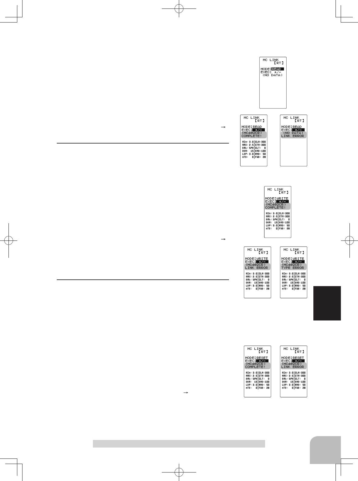
ESC Link Function "MC LNK"
a-Select the setting item "MODE" using the (JOG) button,
and select "READ" by (+) or (-) button.
b-Select the setting item
"
EXEC:+/-
"
using the (JOG) but-
ton, and press the (+) and (-) buttons simultaneously for 1
second or longer.
-"COMPLETE!" blinks on the screen and the ESC type and currently set con-
tents are read.
- If "LINK ERROR" blinks on the screen, communication with the amp is not
being performed normally. Check the T4GRS and ESC connection and the
battery connection to ESC and the ESC power switch and repeat steps a b.
3 (Writing to ESC)
Execute this function to write the setting data to ESC.
a-Select the setting item
"
MODE
"
using the (JOG) button,
and select
"
WRITE
"
by (+) or (-) button.
b-Select the setting item
"
EXEC:+/-
"
using the (JOG) but-
ton, and press the (+) and (-) buttons simultaneously for 1
second or longer.
-"COMPLETE!" blinks on the screen and the setting data is written to ESC.
If "LINK ERROR" blinks on the screen, communication with the amp is not
being performed normally. Check the T4GRS and ESC connection and the
battery connection to ESC and the ESC power switch and repeat steps a b.
In addition, if (NO DATA) is displayed on the T4GRS screen, "WRITE" can-
not be selected because there is no setting data to be written.
- Different type ESC data cannot be written. If writing is attempted, "TYPE
ERROR" will link on the screen to show that the ESC type is wrong.
4 (Initialization)
This function writes the MC setting data set at the factory to
the connected MC and T4GRS. Perform "READ" before per-
forming initialization.
a-Select the setting item "MODE" using the (JOG) button,
and select "RESET" with the (+) or (-) button.
b-Select the setting item "EXEC:+/-" using the (JOG) but-
ton, and press the (+) and (-) buttons simultaneously for ap-
proximately 1 second
- "COMPLETE!" blinks on the screen and the initial data is written to the ESC.
If "LINK ERROR" blinks, communication with the amp was not performed
normally. Check the T4GRS and ESC connection and the battery connection
to ESC and the ESC power switch, and repeat steps a b. In addition, when
(NO DATA) is displayed on the T4GRS screen "RESET" cannot be selected
because there is no written initial data.
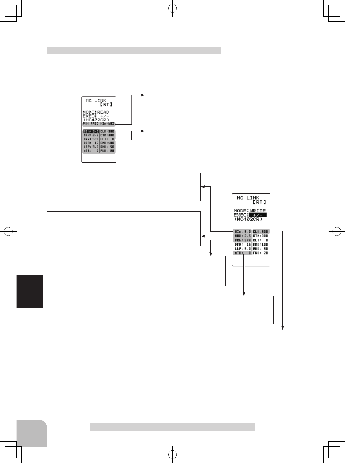
The currently set item is
displayed here.
The item indicated by the
highlighted cursor is se-
lected.
Adjustment buttons
- Use the (+) and (-) buttons to
make adjustments.
- Return to the initial value by
pressing the (+) and (-) buttons
simultaneously (approx. 1 sec).
Setup item selection
- Select by the (JOG) button.
94
Function
MIn-(PWM FREC MIN LD) 100Hz~10000Hz (10kHz)
MC950CR:500Hz~30000Hz (30kHz)
Same as Link software PWM frequency (at Min. load),
MIn sets the "0"A PWM frequency at minimum load.
MAX-(PWM FREC MAX LD) 100Hz~10000Hz (10kHz)
MC950CR:500Hz~30000Hz (30kHz)
Same as Link software PWM frequency (at Max. load).
MAX sets the PWM frequency at maximum load at the output cur-
rent limit value set by Current Limiter.
CLM-(CURRENT LIMIT) 50A~300A (MC950CR:50A~300A), OFF Same as Link software Current Limiter.
Current Limiter sets the current value at maximum load here.
Since setting of the MAX is based on the output current limit value set by Current Limiter, Current Limiter does not
have to be turned OFF except when a current exceeding 300A is generated.
BRK-(PWM FREC BRK LD) nOR(2000Hz)/ HIG(1000Hz)/ SPH(500Hz)
MC950CR:500Hz~30000Hz (30kHz)
Same as Link software Brake PWM at frequency.
This setting can set the brake PWM frequency.
"MIn" which sets the frequency when the load is small, is set to the high frequency side (large value) when extension is desired after straight-
away and curves.
"MAX" which sets the frequency when the load is large, is set to the high frequency side (large value) when you want to suppress the rise
from low speed and when motor heating and commutator roughness are sensed.
When the rise from low speed is poor, and becomes bad even when "MAX" is set to the low frequency side, use the log data to check if there
was a momentary voltage drop. When you want to suppress the overall power, lengthen the run time, and otherwise improve efficiency, set
both "MAX" and "MIn" to the high frequency side. When you want to set a fixed PWM frequency at full range regardless of the load current,
set PWM frequency (at Max. load) and PWM frequency (at Min. load) to the same value.
nTB-(NEUTRAL BRAKE) 0%(OFF)~100%
Same as Link software Neutral Brake.
Use this setting when you want to use the brakes at the neutral throttle (OFF) position by throttle operation. The
larger this value, the greater the braking force. When you want to use the neutral brake, set this value to "0%".
ESC function setup (MC601/602/850/851C, 401/402/950CR)
Setup item
ESC Link Function "MC LNK"
1Select the setting item using the (JOG) button.
Set the value by (+) and (-) button.
95
Function
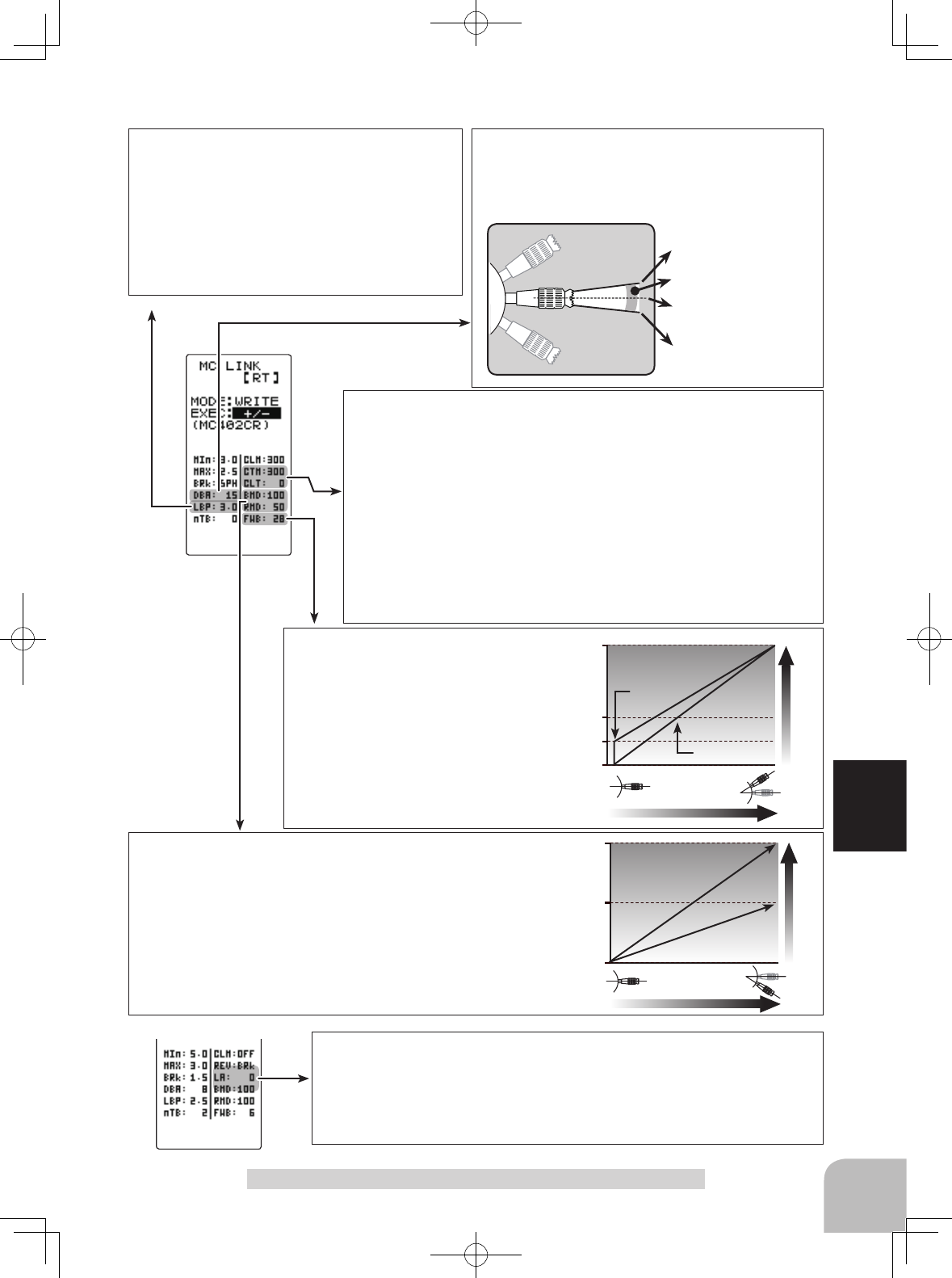
LBP-(LOW BATTERY VOLT) 2.5V~6V
2.5V~7.5V for MC950CR
Same as Link software Low Bat Protection
This setting cuts off the output to the motor when
the main battery voltage drops to the set voltage.
This stops the receiver ceasing operation when the
power to the receiver becomes insufficient whilst
running due to a drop in the power supply voltage.
When the power supply voltage recovers, power is
supplied to the motor once more.
CTM-(C.L. TIME LIMIT) 50A~300A /CLT-(C.L. TIMER) 0sec(OFF)~240sec
(except MC950CR)
Same as Link software Current Limiter (Time Limit)/Current Limit timer.
The output current can be limited up to a set time from the start of running.
This is effective in preventing the motor from outputting wasted energy when
the voltage is high immediately after the power battery was recharged.
- "CTM" (Time Limit) sets the maximum output current for the time the output
current is limited.
- "CLT" sets the time the output current is limited. This function is disabled
when set to "0" sec.
Since the Current Limit Timer starts when the throttle stick is pushed forward
and current is output to the motor, this function begins to operate when the
motor is run during trim adjustment, etc.
100
50
0
%
Brake (Reverse) operation
Braking force
Reverse Power
BMD-(BRAKE MAX DUTY) 0%~100%
Same as Link software Brake Max. Duty.
This setting can set the braking force between the neutral point and Max
brake point. The larger this value, the greater the braking force. When set
to "0%", the brakes are not effective.
RMD-(REVERSE MAX DUTY) w/back only 0%~100%
Same as Link software Reverse Max. Duty
This setting can set the reverse power between the neutral point and Max
reverse point. The larger this value, the greater the reverse power. When
set to "0%", reverse is not effective.
100
50
0
Forward operation
Throttle response
FWB "50"
FWB "0"
FWB-(FORWARD BOOST) 0~100 (except MC850C)
Same as Link software Forward Boost
Operation near the throttle stick (stick) neutral
position becomes a sharp increase.
MC950CR only setup item
REV-(REV CANCEL) BRk /REV Same as Link software Reverse Cancel.
When set to BRk, reverse operation is disabled.
LA-(LEAD ANGLE) 0~1500 Same as Link software Lead Angle.
The lead angle of the motor can be set at the MC950CR side. However, we recommend that it
is normally "0". Since this setting is based setting by referring to the speed log by the Link soft-
ware, independent use of the MC LINK function of the T4GRS is recommended.
ESC Link Function "MC LNK"
Throttle neutral position
Dead Band
Point at which brakes start
taking effect
Position at which motor starts
to run
DBA-(DEAD BAND) ±2μs~±50μs
Same as Link software Dead Band.
This sets the range (neutral point range) over which the
ESC does not respond to transmitter throttle operation.
The larger the set value, the wider this range.
Adjustment buttons
- Use the (+) and (-) buttons to
make adjustments.
- Return to the initial value by
pressing the (+) and (-) buttons
simultaneously (approx. 1 sec).
Setup item selection
- Select by the (JOG) button.
Page1 Page2
To right side
on Page2
To left side
on Page1
96
Function
ESC Link Function "MC LNK"
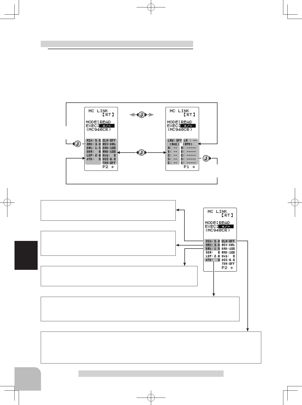
ESC function setup (MC940CR, MC960CR)
1Select the setting item using the (JOG) button.
Set the value by (+) and (-) button.
Operate the following (JOG) button and switch between
Page1 and Page2 of the setup screen.
The cursor positions
"EXEC +/-"
Page1
Setup item
MIn-(PWM FREC MIN LD) 1kHz(1000Hz)~30kHz (30000Hz)
Same as Link software PWM frequency (at Min. load),
MIn sets the "0"A PWM frequency at minimum load.
MAX-(PWM FREC MAX LD) 1kHz(1000Hz)~30kHz (30000Hz)
Same as Link software PWM frequency (at Max. load).
MAX sets the PWM frequency at maximum load at the output cur-
rent limit value set by Current Limiter.
CLM-(CURRENT LIMIT) 50A~500A
Same as Link software Current Limiter.
Current Limiter sets the current value at maximum load here.
Since setting of the MAX is based on the output current limit value set by Current Limiter, Current Limiter does not
have to be turned OFF except when a current exceeding 300A is generated.
BRK-(PWM FREC BRK LD) 1kHz(1000Hz)~30kHz (30000Hz)
Same as Link software Brake PWM at frequency.
This setting can set the brake PWM frequency.
nTB-(NEUTRAL BRAKE) 0%(OFF)~100%
Same as Link software Neutral Brake.
Use this setting when you want to use the brakes at the neutral throttle (OFF) position by throttle operation. The
larger this value, the greater the braking force. When you want to use neutral brake, set this value to "0%".
97
Function
ESC Link Function "MC LNK"
"MIn" which sets the frequency when the load is small, is set to the high frequency side (large value) when extension is desired after straight-
aways and curves.
"MAX" which sets the frequency when the load is large, is set to the high frequency side (large value) when you want to suppress the rise
from low speed and when motor heating and commutator roughness are sensed.
When the rise from low speed is poor, and becomes bad even when "MAX" is set to the low frequency side, use the log data to check if there
was a momentary voltage drop. When you want to suppress the overall power, lengthen the run time, and otherwise improve efficiency, set
both "MAX" and "MIn" to the high frequency side. When you want to set a fixed PWM frequency at full range regardless of the load current,
set PWM frequency (at Max. load) and PWM frequency (at Min. load) to the same value.
LBP-(LOW BATTERY VOLT) 2.5V~7.5V
Same as Link software Low Bat Protection
This setting cuts off the output to the motor when the main battery voltage drops to the set voltage. This stops
the receiver ceasing operation when the power to the receiver becomes insufficient whilst running due to a
drop in the power supply voltage. When the power supply voltage recovers, power is supplied to the motor
once more.
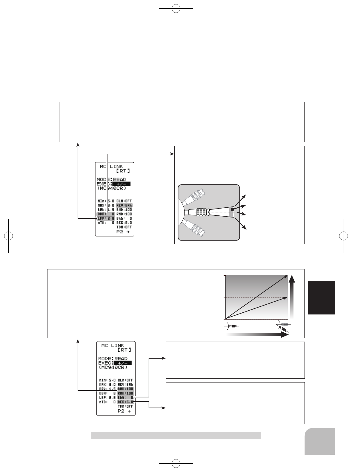
REV-(REV CANCEL) BRk /REV
Same as Link software Reverse Cancel.
When set to BRk, reverse operation is disabled.
DBA-(DEAD BAND) ±2μs~±50μs
Same as Link software Dead Band.
This sets the range (neutral point range) over which the
ESC does not respond to transmitter throttle operation.
The larger the set value, the wider this range.
Page1
Page1
100
50
0
%
Brake (Reverse) operation
Braking force
Reverse Power
BMD-(BRAKE MAX DUTY) 0%~100%
Same as Link software Brake Max. Duty.
This setting can set the braking force between the neutral point and Max
brake point. The larger this value, the greater the braking force. When set
to "0%", the brakes are disabled.
RMD-(REVERSE MAX DUTY) w/back only 0%~100%
Same as Link software Reverse Max. Duty
This setting can set the reverse power between the neutral point and Max
reverse point. The larger this value, the greater the reverse power. When
set to "0%", reverse is disabled.
BKS-(BRAKE SLOPE) 0~300 (Only when used TBM-LEV2)
Same as Link software Brake Slope.
This function adjusts the braking effect when the throttle is
returned (throttle off). It eliminates the effect known as “en-
gine braking” in full sized vehicles.
BEC-(BEC VOLT)
6.0V / 7.4V
Same as Link software BEC Volt.
The receiver BEC voltage can be selected from 6.0V and
7.4V. Match the voltage to the rating of the servo connect-
ed to the same receiver. This BEC voltage cannot output a
voltage higher than the input voltage.
Throttle neutral position
Dead Band
Point at which brakes start
taking effect
Position at which motor starts
to run
98
Function
Page1
TBM-(TURBO MODE)
OFF /LV1 /LV2
Same as Link software Turbo Mode
This function sets the turbo mode. More power can be enabled using the turbo mode. Depcompleted on the
setting, the motor and ESC may be damaged so use this setting carefully.
(Note) When LAU (LEAD ANGLE USE) is off, lead angle setting will not operate even if set to LEV1 or LEV2.
(Turbo mode disabled, TBM=OFF)
OFF mode: (No Lead Angle mode) Lead angle - No
When used in races in which the lead angle setting function is inhibited by ESC, set to this mode. The lead
angle function is disabled in the same manner as if LAU (LEAD ANGLE USE) was turned off.
When the lead angle function is disabled by the method described above, the MC960CR shows that the
lead angle function is off by flashing a blue LED at an ON 0.1 second, OFF 0.9 second cycle at the neutral
point.
LV1 turbo mode: (Lead Angle mode) Lead angle – Yes
The output can be increased by setting a lead angle.
Depcompleted on the set value, the motor may be damaged so increase the lead angle value in steps from
a small value while observing the result.
Turn on LAU (Lead Angle Use) and adjust the lead angle by LA-(LEAD ANGLE) and A, B, C, D, E BA-(A, B,
C, D, E BOOST ANGLE) value.
LV2 power mode: (Power Mode) Lead angle – Yes
Displays still more power than a turbo.
However, since even a motor applies a large load on the ESC, make the lead angle larger in steps from a
small value while observing the result.
Turn on LAU (LEAD ANGLE USE) and adjust the lead angle by LA-(LEAD ANGLE) and A, B, C, D, E BA-(A, B,
C, D, E BOOST ANGLE) value.
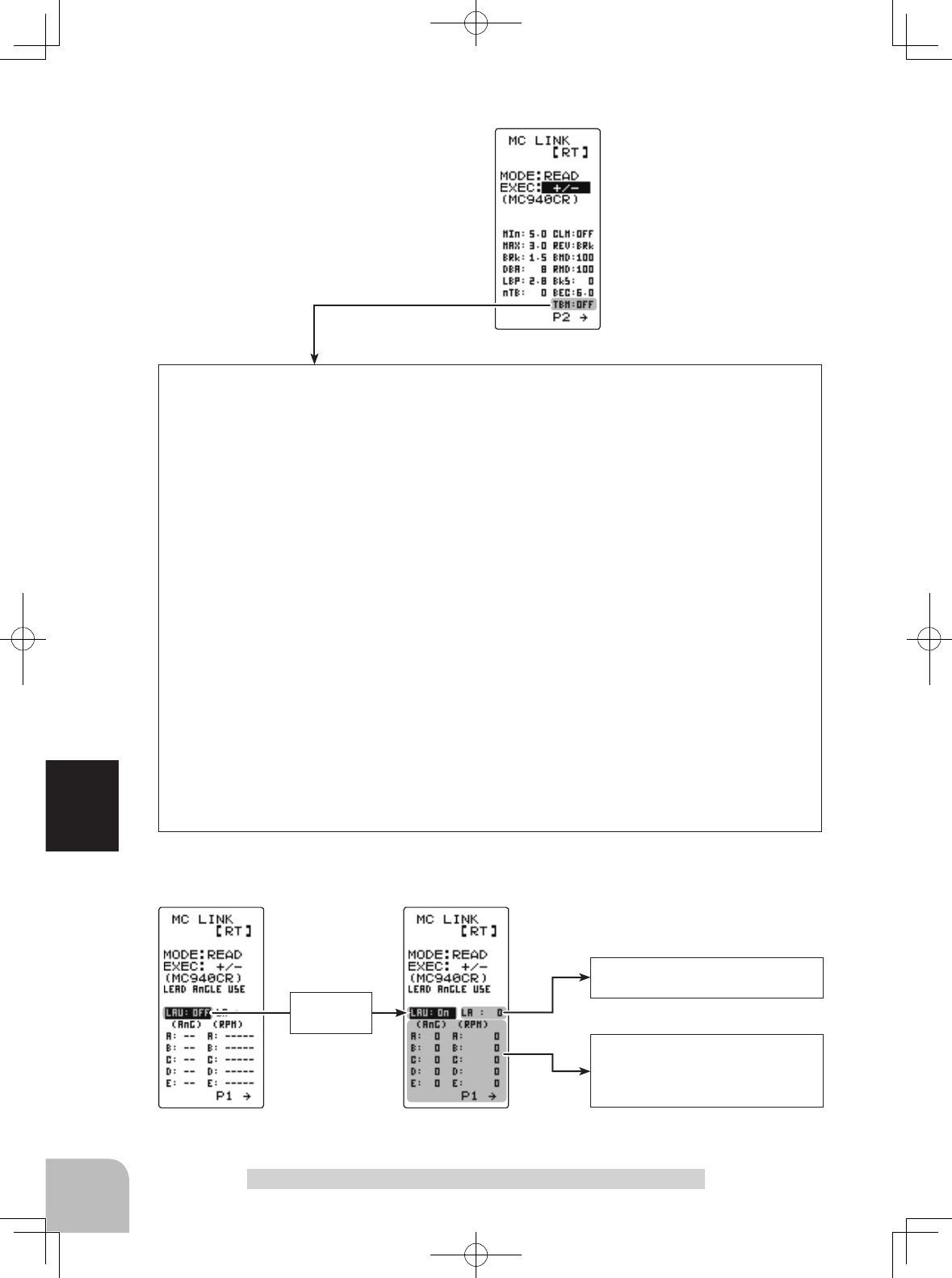
The BOOST ANGLE and BOOST
ANGLE RPM which can set the
lead angle of 5 points relative to
the speed.
Page2 Page2
"LAU"
turned on
"LA" (LEAD ANGLE) is displayed
and the lead angle can be set.
When "LAU" (LEAD ANGLE USE) is turned on "LA" (LEAD ANGLE) is the lead angle can be set. In addition, the "BOOST
ANGLE" and "BOOST ANGLE RPM" can be set.
ESC Link Function "MC LNK"
99
Function
LAU-(LEAD ANGLE USE)
ON /OFF
Same as Link software Lead Angle Use
This function is effective when TBM (Turbo Mode) is LEV1 or LEV2 and
sets whether or not lead angle is used. This setting has priority over the
TURBO MODE setting. When using in races in which the lead angle func-
tion is inhibited by the ESC set this function to OFF.
OFF : Lead angle function not used.
ON : Lead angle used
LA-(LEAD ANGLE) 0~59 deg
Same as Link software Lead Angle
When LAU (LEAD ANGLE USE) is turned on the motor lead angle can
be set at the MC960CR. The lead angle can be set up to 59 degrees in 1
degree increments.
A,B,C,D,E BA-(A,B,C,D,E BOOST ANGLE) 0~59 deg
Same as Link software Boost Angle
A
,B,C,D,E
RPM-(A
,B,C,D,E
BOOST ANGLE RPM) 0~
99990 rpm
Same as Link software Boost Angle rpm
When LAU (LEAD ANGLE USE) is turned on the lead angle versus motor
speed of the 5 points A to E can be set. The lead angle can be set up to
59 degrees in 1 degree increments.
Note: Do not read to the T4GRS an MC940/960CR whose speed was set
to over 99990rpm by Link software side Boost Angle rpm setting.
Page2
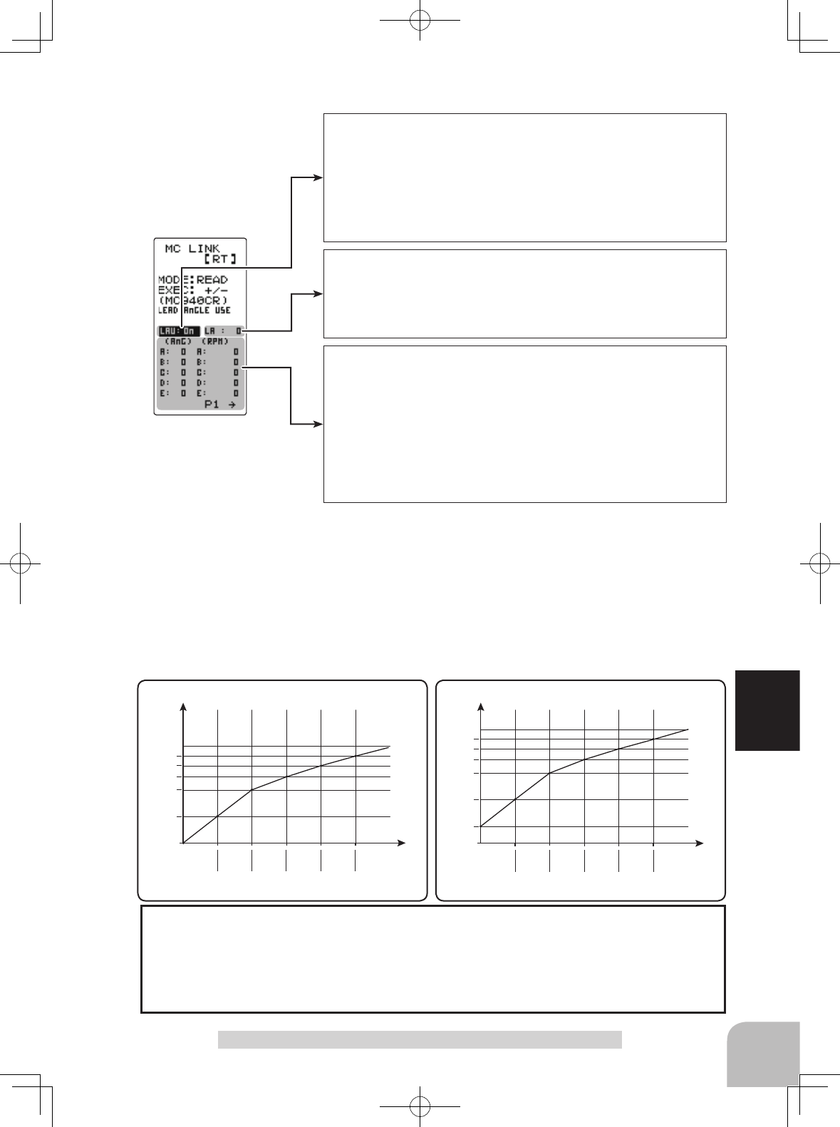
When using in races in which the lead angle setting function is inhibited by the ESC, set LAU (LEAD
ANGLE USE) to OFF. The LAU setting has priority over TBM-(TURBO MODE). If LAU is set to
"OFF", the lead angle setting function can be turned off even if TBM is set to "LV1" or "LV2".
The MC940,960CR shows that the lead angle setting function is OFF ("0" timing) by flashing an
LED.
The LA-(LEAD ANGLE) and A, B, C, D, E BA- (A, B, C, D, E BOOST ANGLE) relationship is shown on
the graphs below. Graph [A] shows the relationship when the same value is set at points A, B, C, D, E BA-
(A, B, C, D, E BOOST ANGLE) of [A] and [B] and the LA-(LEAD ANGLE) was set to "0" and graph [B]
shows the relationship when a value other than "0" was set at LA-(LEAD ANGLE).
As shown in the graphs, [B] is added to the A, B, C, D, E BA-(A, B, C, D, E BOOST ANGLE) set lead an-
gle and [A] is added to the LA-(LEAD ANGLE) set lead angle. For example, if "3" is set at ABA and LA of [B]
is set to "2", the actual ABA becomes 3+2=5 (deg). Since LA of [A] is "0", the actual ABA also becomes
3+0=3 (deg).
RPM(A) RPM(B) RPM(C) RPM(D) RPM(E)
AnG(A)
AnG(B)
AnG(C)
AnG(D)
AnG(E)
RPM(A) RPM(B) RPM(C) RPM(D) RPM(E)
AnG(A)
LA
AnG(B)
AnG(C)
AnG(D)
AnG(E)
B (LA >"0")A (LA ="0") Lead Angle(deg) Lead Angle(deg)
rpmrpm
ESC Link Function "MC LNK"
Connect the communication
port of both T4GRS with the
optional DSC cord.
Communication port
DSC cord for T4PK (option)
(MDL TRANS screen)
Pres
s
(DISP MENU screen)
Pres
s
Select
"
MDL TRANS
"
100
Function
Data Transfer "MDL TRANS"
This function copies the model memory data of one T4GRS to another T4GRS. Con-
nect the communication port of both T4GRS together with the optional DSC cord for
T4PK. Use this function with the T4GRS power switch set to the display side.
Note: If the T4GRS battery voltage drops, the display switches to low battery display.
Therefore, use this function when there is ample battery capacity remaining.
Note: Since the receiving side writes the new contents of the currently selected model
memory, always check the model number before executing this function.
Data is not interchangeable with another type of transmitter.
Display "MDL TRANS" screen by with the T4GRS power switch at the display setting
using following method:
(Preparation)
- Connect the communication port of both transmitters together
with the optional DSC cord for T4PK.
1Set the power switch of both transmitters to the display (DISP)
setting.
Use the (JOG) button and (+) button to display the
"M
DL-
TRN
"
at both transmitter.
Using the Data Transfer function
Data Transfer "MDL TRANS"
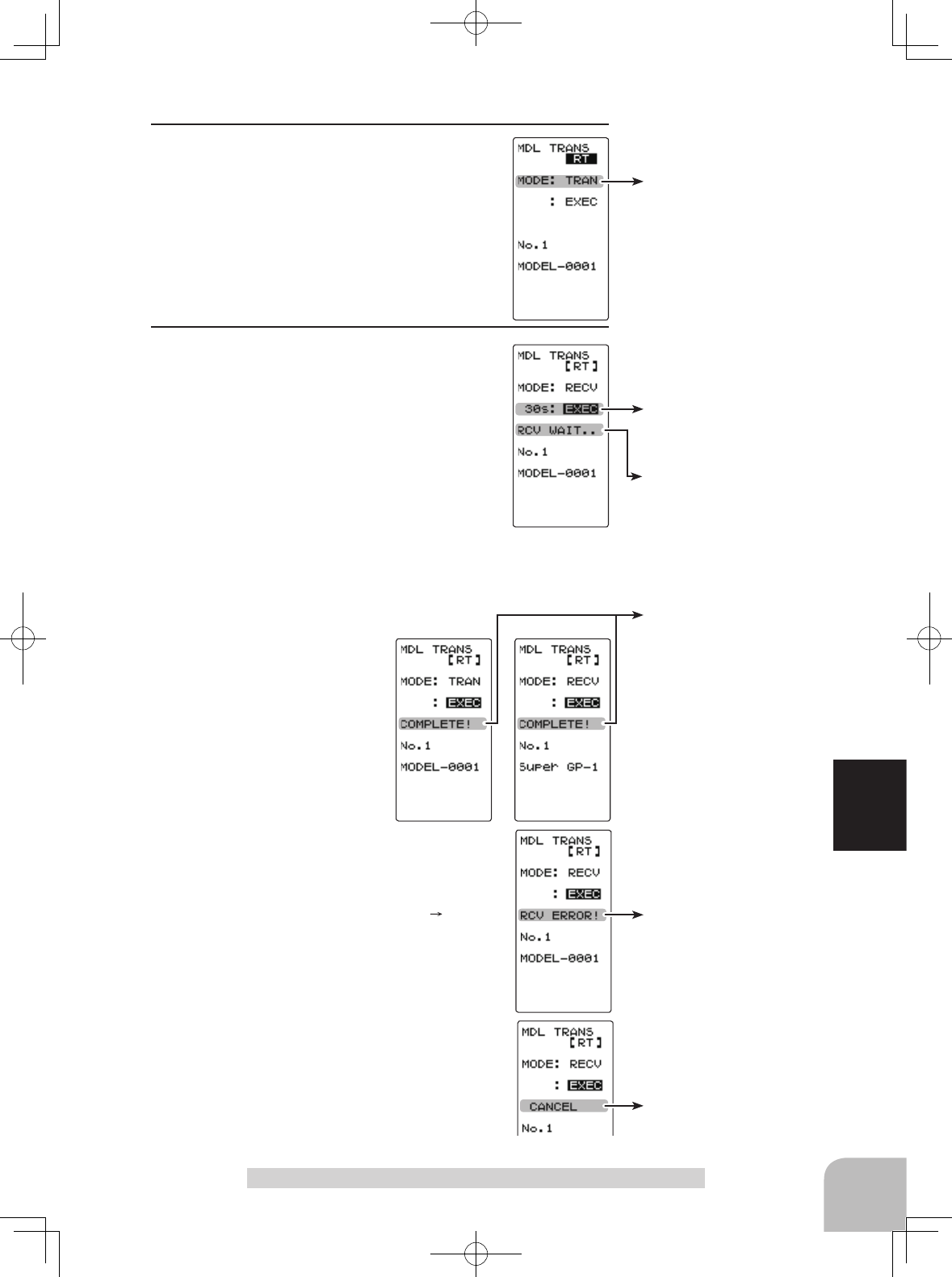
30 seconds wait is displayed
on the receive side screen.
Transfer execution button
- (+) and (-) buttons pressed
simultaneously for about 1
second.
Mode selection
"TRANSFER" "RECEIVE"
Setup item selection
- Select by (JOG) button up or
down operation.
Mode change button
- Use the (+) and (-) buttons to
make adjustments.
"COMPLETE!" is displayed.
"RCV ERROR!" is displayed.
"CANCEL" is displayed.
101
Function
2 (Select the setting item )
"MODE" by the (JOG) button up or down op-
eration, and select the transfer side and re-
ceive side by (+) or (-) button.
"TRAN" :Data transfer side
"RECV" :Data receive side
3 (Data transfer execution)
Select the setting item
"
EXEC
"
using (JOG)
button up or down operation of both transmitter.
First, press the receive side
"
RECV
"
trans-
mitter (+) and (-) buttons simultaneously. The
message
"
RCV WAIT..
"
appears and count
down begins.
Within 30 seconds, press the transfer side
"
TRANS
"
trans-
mitter (+) and (-) buttons simultaneously. (If data transfer is
not executed within 30 seconds, an error will be displayed at
the receive side
"
RECV
"
transmitter.)
-"COMPLETE!" is displayed
on the screen of the receive
side "RECV" transmitter and
data transfer is ended.
-If "RCV ERROR!" is displayed on the screen
of the receive side "RECEIVE" transmitter, da-
ta transfer was not performed normally. Check
the connection and repeat steps 1 3. Since
the transfer side "TRANS" transmitter only
sends, "COMPLETE!" is displayed even when
data transfer was not performed normally.
Data transfer can also be canceled before the
end of transfer by operating the (JOG) button
at a T4GRS that is waiting to receive data.
When completed, return to the DISP MENU
screen by pressing the (JOG) button.
Data Transfer "MDL TRANS"
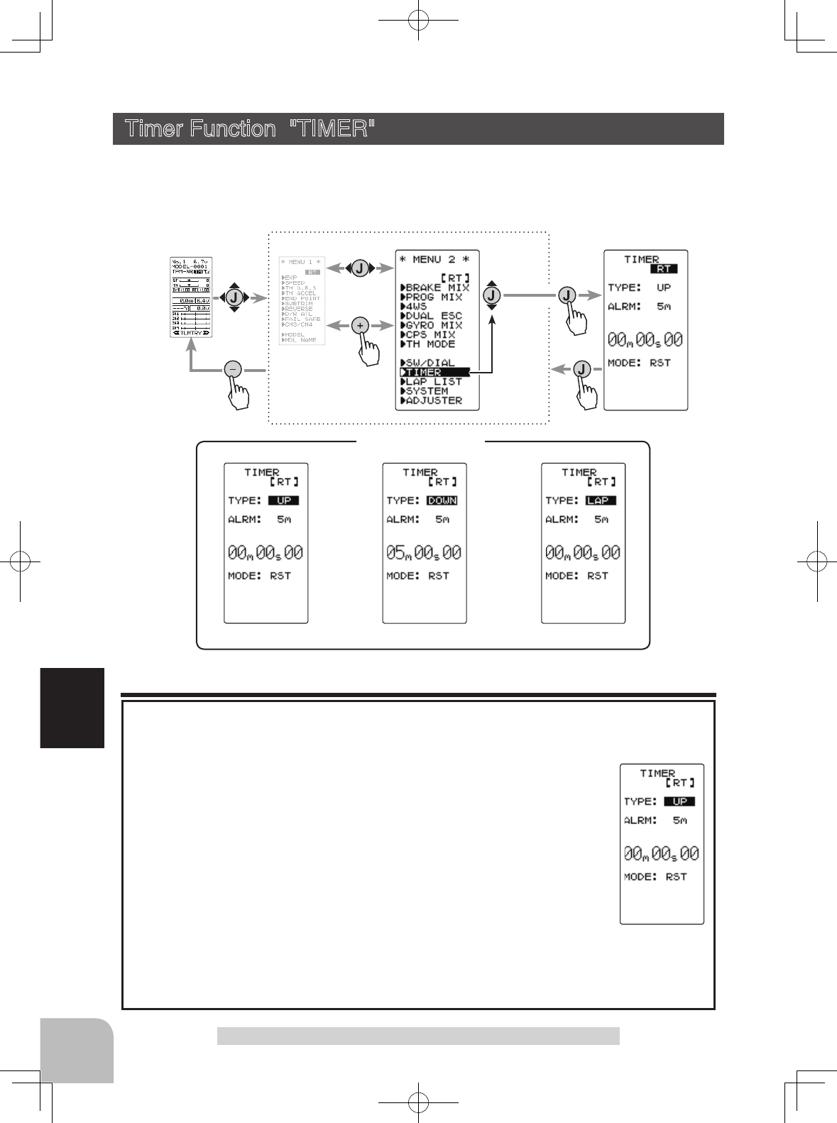
UP TIMER FUEL DOWN TIMER LAP TIMER
TIMER Disply
Pres
s
Pres
s
Pres
s
Pres
s
Select
"
TIMER
"
(HOME screen) (MENU 1 screen) (TIMER screen)
(MENU 2 screen)
102
Function
Timer Function "TIMER"
Use the timer by selecting one of the three timers UP TIMER, DOWN TIMER, and
LAP TIMER.
Display "TIMER" screen by the following method:
UP TIMER function
Up timer function
- This function can be used to count the time between start and stop, etc.
- The timer repeatedly starts and stops each time the switch is pressed and
accumulates the time between each start and stop. When the count reach-
es 99 minutes 99 seconds, the count returns to 00 minutes 00 seconds and
is repeated.
- The rst start operation can be linked to the throttle stick.
- The passage of time is announced by sounding of a buzzer (beep) each
minute after starting.
- Alarm :Beep sounds at the set time (minute).
- Prealarm :Alarm advance announcement sound. Beeping begins 5 seconds before
the alarm.(beeps)
- After starting, the timer continues to count and can be stopped by switch even when
the LCD switches to another screen.
Timer Function "TIMER"
103
Function
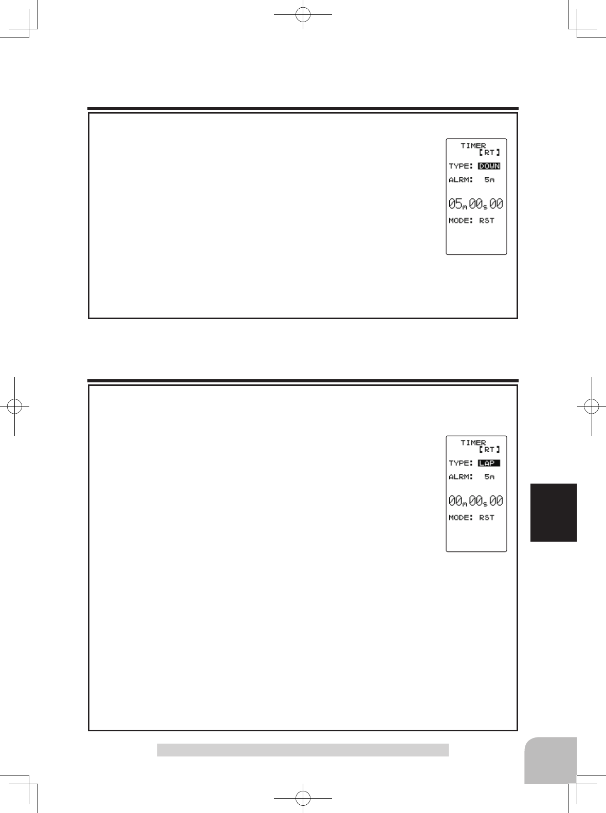
FUEL DOWN TIMER function
Fuel down timer function
- This function is primarily used to check the refueling time of a gasoline
car. (The remaining time is displayed.)
- Each time the switch is pressed, the timer is restarted and the set time is
reset. The start time becomes the alarm set time. (When counted down to
00 minute 00 second, the down timer becomes an up timer.)
- The down timer can be initially started by throttle stick.
- The passing of time is indicated by sounding of a buzzer (beep) each
minute after starting.
- Alarm :A beep sounds at the set time (minute).
- Prealarm :Alarm advance announcement sound. Beeping begins 5 seconds before the alarm.(beeps)
- After starting, the timer continues to count even if the LCD switches to another screen.
Timer Function "TIMER"
LAP TIMER
Lap timer function
- Each lap time can be memorized by switch operation. (100 laps)
- The race time can be set. Switch operation after the time set by alarm
has elapsed automatically stops the timer. The passing of time is indi-
cated by sounding of a buzzer (beep) each minute after starting.
-Alarm :Beep sounds at the set time.
Prealarm :Alarm advance announcement sound. Sounding begins 5 seconds before
the alarm. (beeps)
- The lap timer can be initially started by throttle stick.
(LAP TIMER operation)
- The lap timer is started by switch or throttle stick.
- Number of laps (LAP): After starting, the timer is counted up and the lap time blinks for 3 seconds
each time the switch is pressed. To prevent erroneous counting, switch operation is not accepted
during this period. When 1 lap exceeds 10 minutes, counting is repeated from 0.
- Lap list: Up to 100 lap times are memorized beginning from lap list 1. After lap memory "No.100", op-
eration returns to lap memory "No.1" and the lap memories are overwritten.
- The lap time data memorized in the lap memories can be checked with the lap list screen. The entire
lap list data is cleared the next time the lap timer is started.
- TIME: For the first 3 seconds, the preceding lap time is displayed. After that the current lap time is
displayed.
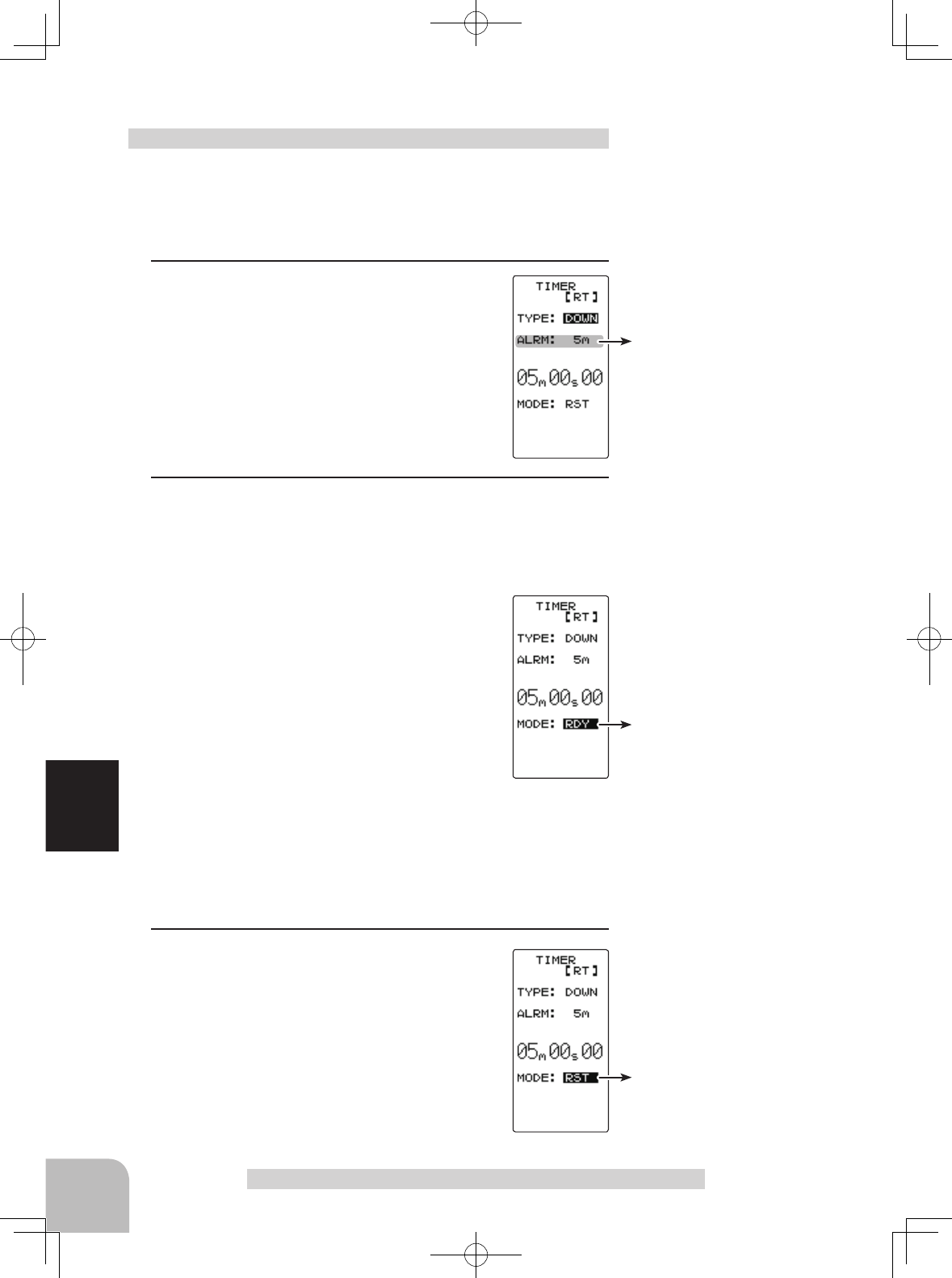
Status display
RST :Reset state
RDY :
Throttle stick operation wait
RUN :Timer running
STP : Timer stopped
104
Function
Timer selection
First, select the type of timer
at the "TYPE" item. The setup
screen varies depcompleted
on the type of timer. This figure
shows the UP TIMER setup
screen.
Timer Function "TIMER"
(Preparation)
Assign the "TIMER" switch using the function select switch .
1 (Racing timer type selection)
Select the setting item "TYPE" using the (JOG) button. Use
the (+) or (-) button and set the racing timer type.
Timer selection (TYPE)
UP : Up timer
DOWN : Down timer
LAP : Lap timer
2When completed, return to the MENU2 screen by pressing
the (JOG) button.
Racing timer type selection
Time display
Minute display (m)
Second display (s)
1/100 second display
Setup item selection
- Select by the (JOG) button.
Adjustment buttons
- Use the (+) and (-) buttons to
make adjustments.
Timer screen
Alarm time (ALRM)
OFF, 1 ~ 99 m
Initial value: 5 m
Status display
RST :Reset state
RDY :
Throttle stick operation wait
RUN :Timer running
STP : Timer stopped
Status display
RST :Reset state
RDY :
Throttle stick operation wait
RUN :Timer running
STP : Timer stopped
Switches
Time start / stop
105
Function
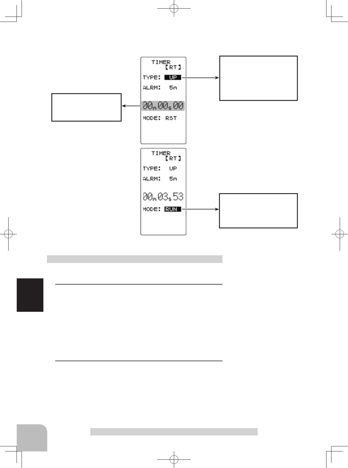
Timer Function "TIMER"
(Preparation)
Select the setting item "TYPE" using the (JOG) button.
Press the (+) or (-) button and select "UP".
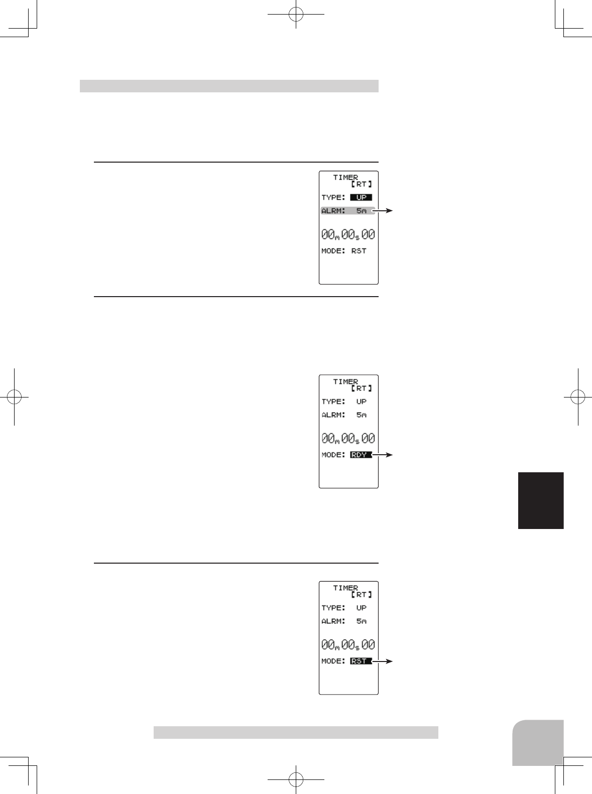
1 (Alarm time setting)
Select the setting item "ALRM" using the (JOG)
button and set the alarm time with the (+) or (-)
button.
2 (Timer start/stop operation)
Start the timer by pressing the switch ("TIMER") set by func-
tion select switch function.
Stop the timer with the same switch ("TIMER") as start.
- Linking start only to the throttle stick
Select the setting item "RST" using the (JOG)
button and press the (+) and (-) buttons simul-
taneously for approximately 1 second. When
the set beeps and the status display switches
from "RST" to blinking "RDY", the system en-
ters the stick operation ready state. When the
stick is operated in the forward direction, the
timer starts. (Status display "RUN")
If the (JOG) button is pressed while the timer is operating,
the LCD returns to MENU2 screen.
3 (Timer reset operation)
Select a status display ("RUN", "STP", or
"RDY") direction the (JOG) button and press
the (+) and (-) buttons simultaneously for ap-
proximately 1 second. A beep is generated
and "RST" appears on the status display and
the timer resets.
Using the up timer
Adjustment buttons
- Use the (+) and (-) buttons to
make adjustments.
- Press the (+) and (-) buttons si-
multaneously (approx. 1 sec) to
return to the HOME screen.
Alarm time (ALRM)
OFF, 1 ~ 99 m
Initial value: 5 m
Status display
RST :Reset state
RDY :
Throttle stick operation wait
RUN :Timer running
STP : Timer stopped
Status display
RST :Reset state
RDY :
Throttle stick operation wait
RUN :Timer running
STP : Timer stopped
106
Function
Timer Function "TIMER"
(Preparation)
Select the setting item "TYPE" using the (JOG) button.
Press the (+) or (-) button and select "DOWN".
1 (Alarm time setting)
Select the setting item "ALRM" using the (JOG)
button and set the alarm time with the (+) or (-)
button.
2 (Alarm start/restart operation)
When the switch ("TIMER") set by function select switch
function is pressed, the timer starts. When the same switch
("TIMER") is pressed while the timer is operating, the timer is
reset and simultaneously restarted. (Restart)
- Linking start only to the throttle stick
Select the setting item "RST" using the (JOG)
button and press the (+) and (-) buttons simul-
taneously for about 1 second. When the set
beeps and the status display switches from
"RST" to blinking "RDY", the system enters
the stick operation ready state.
When the stick is operated in the forward direction, the timer
starts. (Status display "RUN")
If the (JOG) button is pressed while the timer is operating,
the LCD returns to MENU2 screen.
3 (Timer reset operation)
Select a status display ("RUN") using the
(JOG) button and press the (+) and (-) buttons
simultaneously for approximately 1 second.
A beeping sound is generated and "RST" ap-
pears on the status display and the timer re-
sets.
Using the fuel down timer
Adjustment buttons
- Use the (+) and (-) buttons to
make adjustments.
- Press the (+) and (-) buttons si-
multaneously (approx. 1 sec) to
return to the HOME screen.
Switches
Timer start / restart

Status display
RST :Reset state
RDY :
Throttle stick operation wait
RUN :Timer running
GOAL: Timer stopped
Status display
RST :Reset state
RDY :
Throttle stick operation wait
RUN :Timer running
GOAL: Timer stopped
Alarm time (ALRM)
OFF, 1 ~ 99 m
Initial value: 5 m
107
Function
Timer Function "TIMER"
(Preparation)
Select the setting item "TYPE" using the (JOG) button.
Press the (+) or (-) button and select "LAP".
1(Alarm time setting)
Select the setting item "ALRM" using the (JOG)
button and set the alarm time with the (+) and
(-) buttons.
2(Timer start/ lap count/ stop operation)
When the Timer switch (set in the Function select menu) is
pressed, the timer starts. During operation, the same switch
becomes the lap switch and when the set time elapses, the
timer is stopped by the same switch (TIMER)
- Linking start only to the throttle stick
Select the setting item "RST" by the (JOG)
button and press the (+) and (-) buttons simul-
taneously for about 1 second. When the set
beeps and the status display switches from
"RST" to blinking "RDY", the system enters
the stick operation ready state. When the stick
is operated in the forward direction, the timer
starts. (Status display "RUN")
When the switch (TIMER) is pressed after the time set by
alarm has elapsed, the timer stops and the lap time and total
time are memorized. The status display becomes "GOAL".
If the (JOG) button is pressed while the timer is operating,
the LCD returns to MENU2 screen.
3(Timer reset operation)
Select a status display ("GOAL") using the
(JOG) button and press the (+) and (-) buttons
simultaneously for approximately 1 second.
A beeping sound is generated and "RST" ap-
pears on the status display and the timer re-
sets.
- If the reset operation was performed before the "ALRM"
set time had elapsed, the total time is not memorized.
- The lap memory data can be checked with the lap list
screen.
Using the Lap timer Adjustment buttons
- Use the (+) and (-) buttons to
make adjustments.
- Press the (+) and (-) buttons si-
multaneously (approx. 1 sec) to
return to the HOME screen.
Switches
Timer start / Lap count
Reset button
- Reset by pressing the (+) and
(-) buttons simultaneously for
about 1 second.
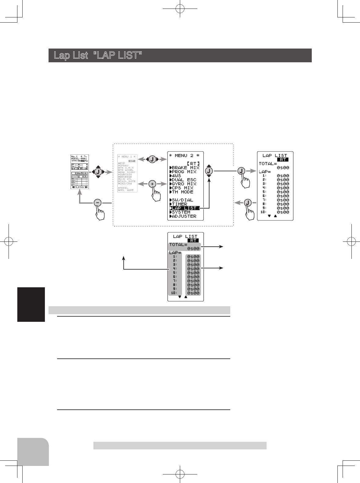
Lap memory No. display
Total time display
Lap time display
Pres
s
Pres
s
Pres
s
Pres
s
Select
"
LAP LIST
"
(HOME screen) (MENU 1 screen) (LAP LIST screen)
(MENU 2 screen)
108
Function
Lap List "LAP LIST"
Lap List "LAP LIST"
The lap list is displayed when checking the lap memory data (lap times) memorized by
lap timer operation.
- After the lap timer starts, the lap times are memorized sequentially each time the
switch is operated.
- If the timer is stopped after the set ALRM time has elapsed, the nal lap time is mem-
orized and the total time after the last lap is automatically written.
- When the timer was stopped before the set ALRM time has elapsed, the total time is not memorized.
Display "LAP LIST" screen by the following method:
1 (Lap memory check)
When the (JOG) button is pressed, the list is scrolled every
10 laps and each lap time can be checked.
2 (Lap memory total data reset)
Press the (+) and (-) buttons simultaneously for approximate-
ly 1 second. A beeping sound is generated and all the data is
reset.
3When completed, return to the MENU2 screen by pressing
the (JOG) button.
Using the lap memory
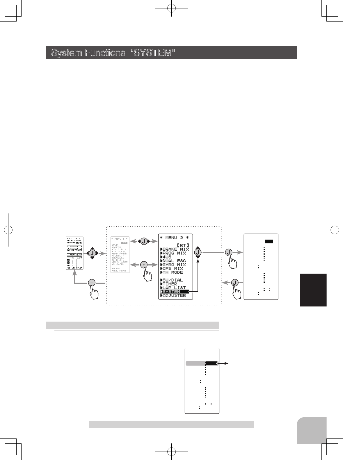
Display "SYSTEM" screen by the following method:
Pres
s
Pres
s
CONTRA
LHT-TM
BK-LHT
SYSTEM
LHT-PW
BATT DRY4
OPE-TM
BUZZER
MENU
TH-STK
DISP
0
ALL
10s
15
65
OFF
TLMTR
ENG
5 5
RT
Pres
s
Pres
s
Select
"
SYSTEM
"
(HOME screen) (MENU 1 screen) (SYSTEM screen)
(MENU 2 screen)
Contrast (CONTRA)
-10~0~+10
Initial value: 0
CONTRA
LHT-TM
BK-LHT
SYSTEM
[ RT ]
LHT-PW
BATT DRY4
OPE-TM
BUZZER
MENU
TH-STK
DISP
ALL
10s
15
65
OFF
TLMTR
ENG
5 5
0
109
Function
System Functions "SYSTEM"
System Functions "SYSTEM"
The graphic liquid crystal screen display mode, buzzer sound and menu character mode,
etc. can be set.
- "CONTRA"---Liquid crystal screen contrast adjustment (20 steps)
- "BK-LHT"---Liquid crystal screen backlighting display mode setup
(OFF, ON at button operation, normally ON)
- "LHT-TM"---Setting of ON time (1~30 secs) when [ON at button operation] was selected above.
- "LHT-PM"---Liquid crystal screen backlighting brightness adjustment (30 steps)
- "BATT"---Battery type setting (LiFe2/NiMH5/DRY4)
The T4GRS can use an optional rechargeable battery. However, the battery alarm setting is dif-
ferent from that of the dry cell battery (alkaline battery recommended). Therefore, always set the
battery type to match the power source used.
If used with the incorrect setting, the normal low battery alarm function will not work and the sys-
tem may stop before a battery alarm is generated. The usage time may also become extremely
short.
- "BUZZER"---Buzzer sound tone adjustment (OFF, 100 steps)
- "OPE-TM"---Alarm Setting if Tx is left switched ON (OFF, 10 m)
- "MENU"---Item which displays the basic menu screen in katakana characters for Japanese use.
- “TH-STK”---This is used, when the neutral adjuster of throttle stick is changed, or when it is
changed into ratchet.(5:5, 7:3, F10)
- "DISP"---HOME screen display mode setting (Telemetry data, Timer, Users name)
1(Setting of each item)
(Adjusting the liquid crystal contrast)
Select the setting item "CONTRA" using
the
(JOG) button
, and use the (+) and (-) buttons to
adjust the screen contrast.
- Adjust to an easy-to-see contrast.
When completed, return to the MENU2 screen
by pressing the (JOG) button.
System function setup Adjustment buttons
- Use the (+) and (-) buttons to
make adjustments.
- Press the (+) and (-) buttons si-
multaneously (approx. 1 sec) to
return to the initial value.
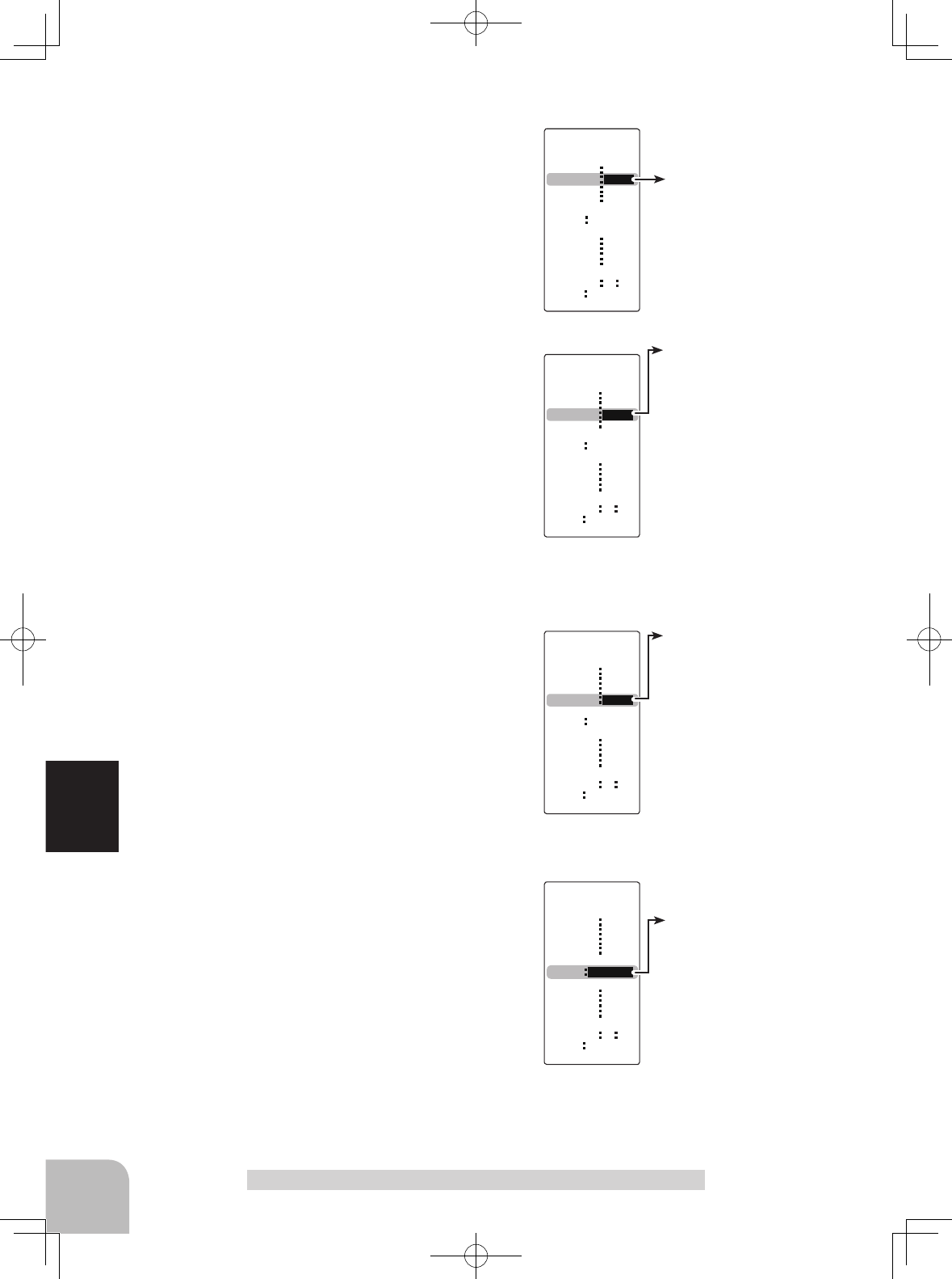
Backlight mode (BK-LHT)
KEY, ALL, OFF
Backlighting time (LHT-TM)
1~30
Initial value: 10
Backlighting brightness
(LHT-PW)
1~30
Initial value: 15
CONTRA
LHT-TM
BK-LHT
SYSTEM
[ RT ]
LHT-PW
BATT DRY4
OPE-TM
BUZZER
MENU
TH-STK
DISP
15
65
OFF
TLMTR
ENG
5 5
0
ALL
10s
CONTRA
LHT-TM
BK-LHT
SYSTEM
[ RT ]
LHT-PW
BATT DRY4
OPE-TM
BUZZER
MENU
TH-STK
DISP
10s
15
65
OFF
TLMTR
ENG
5 5
0
ALL
CONTRA
LHT-TM
BK-LHT
SYSTEM
[ RT ]
LHT-PW
BATT DRY4
OPE-TM
BUZZER
MENU
TH-STK
DISP
65
OFF
TLMTR
ENG
5 5
0
ALL
10s
15
Battery Type (BATT)
LiFe2, DRY4, NiMH5
CONTRA
LHT-TM
BK-LHT
SYSTEM
[ RT ]
LHT-PW
BATT
OPE-TM
BUZZER
MENU
TH-STK
DISP
65
OFF
TLMTR
ENG
5 5
0
ALL
10s
15
DRY4
110
Function
System function setup
(Setting the liquid crystal backlighting mode)
Select the setting item "BK-LHT" using
the (JOG)
button
, and select the mode by pressing the (+)
or (-) button.
"KEY" :Fixed time backlighting ON after button operated.
"ALL" :Backlighting always ON
"OFF" :Backlighting OFF
When completed, return to the MENU2 screen
by pressing the (JOG) button.
(Setting liquid crystal backlighting time)
Select the setting item "LHT-TM" using
the (JOG)
button
, and use the (+) and (-) buttons to set the
ON time.
- When "KEY" is set at the preceding item, this ON time be-
comes effective
.
When completed, return to the MENU2 screen
by pressing the (JOG) button.
(Setting liquid crystal backlighting brightness)
Select the setting item "LHT-PW" using
the
(JOG) button
, and use the (+) and (-) buttons to
set the ON time.
-If too set too bright, the battery will quickly be flattened.
When completed, return to the MENU2 screen
by pressing the (JOG) button.
(Setting the battery type)
Select the setting item "BATT" using the (JOG)
button, and select the mode by pressing the
(+) or (-) button. When changing the battery
type, press the (JOG) button after thorough-
ly checking that the correct battery type has
been entered. An electronic beeping sound is
generated and the setting is changed.
Note: If the battery type is changed to the wrong setting, the
low battery alarm will be generated immediately after the
change and operation will become impossible.
When the low battery alarm was generated, turn off the power and replace the bat-
tery with a fully charged battery or a new dry cell battery and then reset the battery
type.
System Functions "SYSTEM"
Buzzer tone (BUZZER)
OFF, 1~100
Initial value: 85
Voltage display
When BATT is set to dry cell
use DRY4 or LiFe2/NiMH5,
the voltage display of the
HOME screen changes.
CONTRA
LHT-TM
BK-LHT
SYSTEM
[ RT ]
LHT-PW
BATT
OPE-TM
BUZZER
MENU
TH-STK
DISP
OFF
TLMTR
ENG
5 5
0
ALL
10s
15
DRY4
65
DRY4 LiFe2, NiMH5
The power off forgotten alarm
(OPE-TM)
10m, OFF
CONTRA
LHT-TM
BK-LHT
SYSTEM
[ RT ]
LHT-PW
BATT
OPE-TM
BUZZER
MENU
TH-STK
DISP TLMTR
ENG
5 5
0
ALL
10s
15
DRY4
65
OFF
111
Function
Note: If used with the incorrect setting, a normal low battery alarm will not be gen-
erated and the system may stop before the battery alarm is generated. The usage
time may also become extremely short.
"LiFe2" :Futaba LiFe type battery (FT2F1700BV2 / 2100BV2)
"NiMH5" :Futaba MiMH type battery (HT5F1800B)
"DRY4" :Dry cell battery (alkaline battery recommended) 4 batteries
System Functions "SYSTEM"
When completed, return to the menu screen
by pressing the (JOG) button.
(Adjusting the buzzer tone)
Select the setting item "BUZZER" using
the
(JOG) button
, and use the (+) and (-) buttons
to adjust the tone.
- Decide by referring to the tone at adjustment.
When completed, return to the menu screen
by pressing the (JOG) button.
(Changing the Alarm Setting if Tx is left switched ON)
Select the setting item "OPE-TM" using
the
(JOG) button
, and use the (+) and (-) buttons to
select the alarm setting if Tx is left switched ON
mode.
"10m" :If an operation is not performed within 10 min-
utes while the power is on, an audible alarm
sounds.
"OFF" :Alarm setting if Tx is left switched ON is OFF
When completed, return to the menu screen by pressing the
(JOG) button.
CONTRA
LHT-TM
BK-LHT
SYSTEM
[ RT ]
LHT-PW
BATT
OPE-TM
BUZZER
MENU
TH-STK
DISP
5 5
0
ALL
10s
15
DRY4
65
OFF
ENG
TLMTR
USERTIMERTLMTR
Menu character (MENU)
ENG,
CONTRA
LHT-TM
BK-LHT
SYSTEM
[ RT ]
LHT-PW
BATT DRY4
OPE-TM
BUZZER
MENU
TH-STK
DISP
0
ALL
10s
15
65
OFF
TLMTR
5 5
ENG
Throttle stick (TH-STK)
5:5, 7:3, F10 (forward only)
CONTRA
LHT-TM
BK-LHT
SYSTEM
[ RT ]
LHT-PW
BATT DRY4
OPE-TM
BUZZER
MENU
TH-STK
DISP
0
ALL
10s
15
65
OFF
TLMTR
ENG
5 5
HOME screen mode (DISP)
TLMTR, TIMER, USER
When changed into F10
(forward only), brake set-up
cannot be activated.
The display of "NO BRAKE"
or " ---" comes out on
each screen, and a setup is
impossible.
GR
112
Function
System Functions "SYSTEM"
(Changing the menu character display)
Select the setting item "MENU" using the
(JOG) button, and set the basic menu char-
acter display with the (+) or (-) button.
"ENG" : Basic menu displayed in Alphabetic character.
" " : Basic menu displayed in katakana character.
When completed, return to the menu screen by pressing the
(JOG) button.
(When the neutral adjuster of throttle stick is changed )
Select the setting item "TH-STK" using the
(JOG) button, and set the neutral adjuster po-
sition mode with the (+) or (-) button.
"5:5" :Normal
"7:3" :Forward stick travel is increased
"F10" :When ratchet is being used (for GP boat)
Press the (JOG) button after thoroughly
checking whether or not the mistake was
made again. An electronic beeping sound is
generated and the setting is changed.
When completed, return to the menu screen by pressing the
(JOG) button.
(Changing the HOME screen display mode)
Select the setting item “DISP” using the (JOG)
button, and set the HOME screen display
mode with the (+) or (-) button.
“TLMTR” :Telemetry data is displayed
“TIMER” :Timer is displayed
“USER” :User name is displayed
Only the T-FHSS system can display telemetry data.
Nothing is displayed with an S-FHSS/FHSS system.
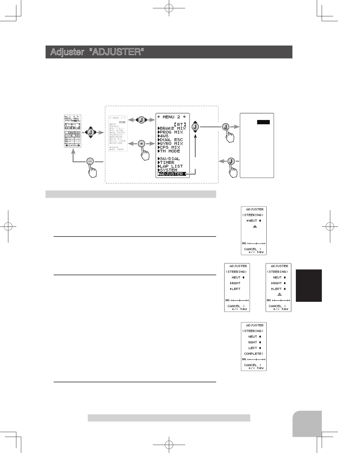
fig-1
fig-4
fig-2 fig-3
Pres
s
Pres
s
ADJUSTER
*STEERING
*THROTTLE
[ RT ]
Pres
s
Pres
s
Select
"
ADJUSTER
"
113
Function
Adjuster "ADJUSTER"
(Preparation)
On the ADJUSTER screen, select the setting item "Steering"
using the (JOG) button, and pressing the (JOG) button.
1 (Steering neutral adjustment)
In the neutral setup screen (fig-1) state, pull the stick back
slightly then allow to return to neutral and press the (JOG)
button whilst ensuring the stick is not touched.
2 (Steering throw adjustment)
In the throw setup screen state (fig-2), lightly turn the stick
fully to the left or right and when button mark (fig-3) is dis-
played, pressing the (JOG) button.
Internal check is performed automatically. When each adjust-
ment point is within a fixed range, correction is performed
and "COMPLETE" (fig-4) is displayed.
If an adjustment point is not within a fixed range, correction
is not performed and the correction data is not updated.
When button mark is not displayed even though correction
was performed again, please contact a Futaba Radio Control
Customer Center.
3When completed, return to the MENU2 screen by pressing
the (JOG) button.
Steering adjustment
Adjuster "ADJUSTER"
Steering stick and throttle stick neutral position and servo operating angle correction
can be applied. This is used when a mechanical offset has occurred for some reason.
*
However, when correction is made, the set value of all the setting functions must
be rechecked.
Display the adjuster screen from the system menu.
(HOME screen) (MENU 1 screen) (ADJUSTER screen)
(MENU 2 screen)
5:5 7:3
Neutral Adjuster
(Throttle stick)
114
Function
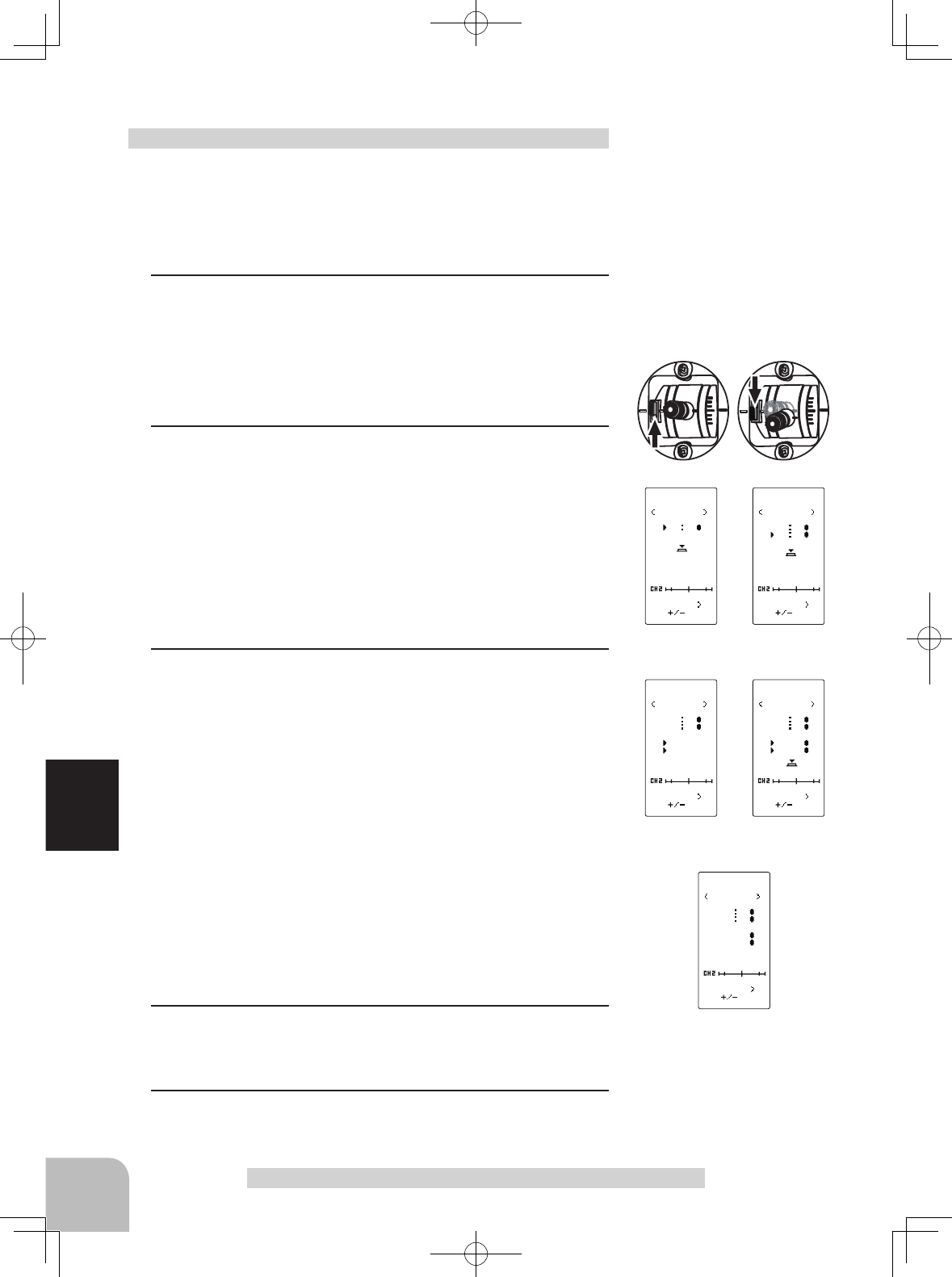
Adjuster "ADJUSTER"
(Preparation)
On the ADJUSTER screen, select the setting item "THROT-
TLE" using the (JOG) button, and press the (JOG) button.
Throttle adjustment will not be made if it has been converted
to ratchet operation. It is necessary to return to a self neutral.
Throttle adjustment
Key
CANCEL
ADJUSTER
THROTTLE
N5 5
Key
CANCEL
ADJUSTER
THROTTLE
N5 5
N7 3
Key
CANCEL
ADJUSTER
THROTTLE
N5 5
N7 3
BRK
FWD
Key
CANCEL
ADJUSTER
THROTTLE
N5 5
N7 3
BRK
FWD
fig-1
fig-3
fig-2
fig-4
1 (Throttle 5:5 neutral adjustment )
Neutral adjuster is set to 5:5 by the Neutral Adjuster switch.
In the 5:5 neutral setup screen (fig-1) state, pull the stick
back slightly then allow to return to neutral and press the
(JOG) button whilst ensuring the stick is not touched.
2 (Throttle 7:3 neutral adjustment )
Neutral adjuster is set to 7:3 by the Neutral Adjuster switch.
In the 7:3 neutral setup screen (fig-2) state, pull the stick
back slightly then allow to return to neutral and press the
(JOG) button whilst ensuring the stick is not touched.
Note that both the 5:5 and 7:3 neutral adjustment procedures
have to be completed as part of the set-up process. Once
complete the required option should be selected.
3 (Throttle throw adjustment)
In the throw setup screen state (fig-3), gently move the stick
fully to the brake side and the forward side and when button
mark (fig-4) is displayed, pressing the (JOG) button.
Internal check is performed automatically. When each adjust-
ment point is within a fixed range, correction is performed
and “COMPLETE!” (fig-5) is displayed.
If an adjustment point is not within a fixed range, correction
is not performed and the correction data is not updated.
When button mark is not displayed even though correction
was performed again, please contact a Futaba Radio Control
Customer Center.
4When completed, return to the ADJUSTER screen by press-
ing the (JOG) button.
5Next, move the cursor to [RT] using the (JOG) button, and press
the (JOG) button.
Key
CANCEL
ADJUSTER
THROTTLE
N5 5
N7 3
BRK
FWD
COMPLETE!
fig-5
Telemetry info
(HOME screen)
115
Function
Info
Info
Info
Info
Signal
Info
Temperature
Sensor
RPM Sensor
Voltage Sensor
Battery voltage is displayed
at the transmitter.
Power battery voltage is
displayed at the transmitter.
voltage
T-FHSS Receiver
Transmitter
Switch
Connect to S.BUS2 Connector
HUB
HUB
Temperature Sensor (SBS-01T)
RPM Sensor (SBS-01RM)
Voltage Sensor (SBS-01V)
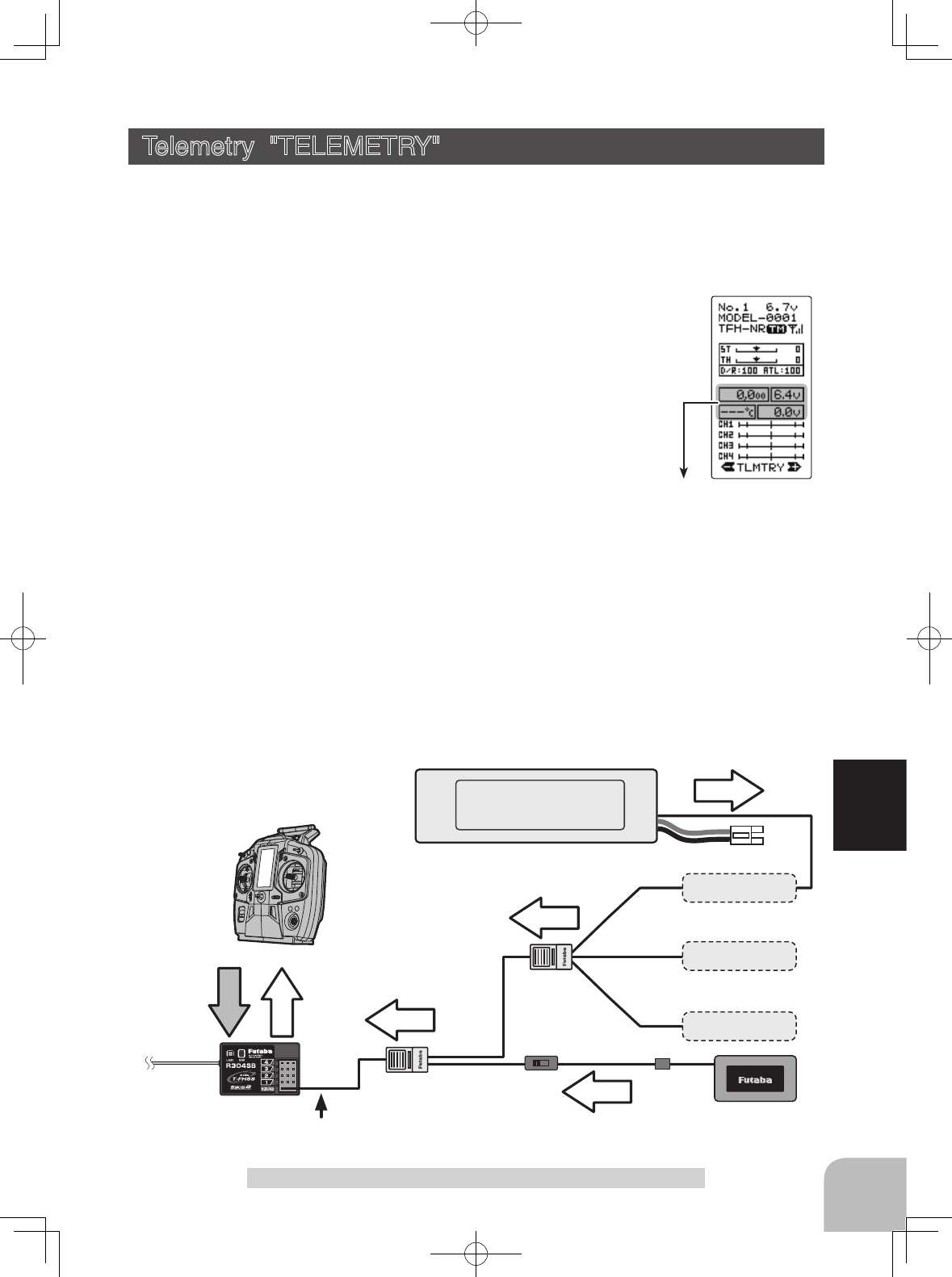
Telemetry "TELEMETRY"
Telemetry "TELEMETRY"
With the telemetry system, the running status can be displayed at the transmitter and
also recorded as a data log by mounting various sensor units to the chassis.
The telemetry related screens are only displayed when the T4GRS power switch is in the
PWR ON position. When the power switch is in the DISP position, the telemetry related
screens are not displayed.
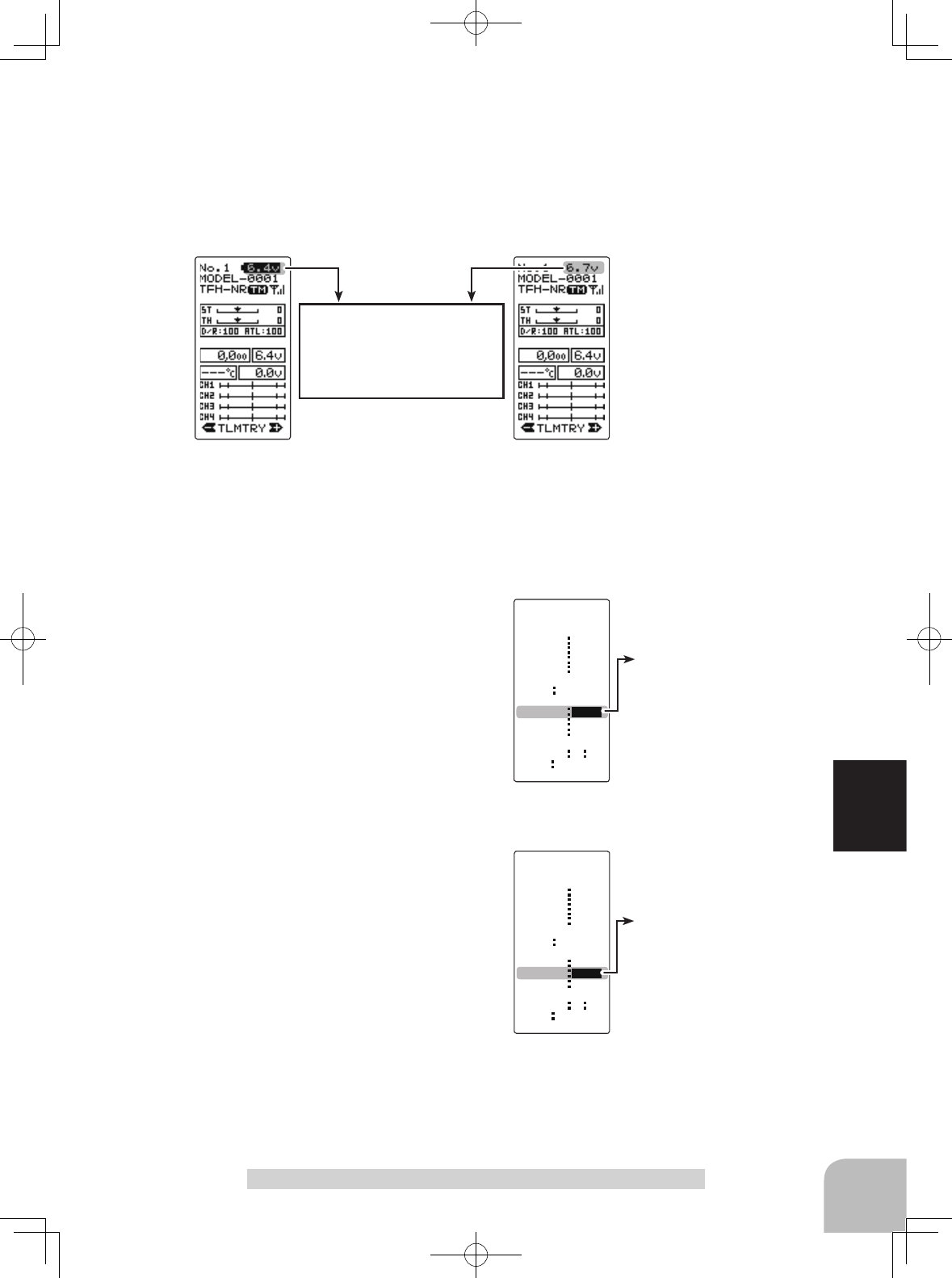
The T4GRS displays four kinds of information on the HOME screen;
receiver power source (battery) voltage, external power supply (drive bat-
tery) voltage, speed, and temperature.
*The telemetry function is compatible with only the T-FHSS system.
*The telemetry function requires a corresponding receiver (R304SB,R304SB-E).
*Only T4GRS with R304SB(-E) ID registered have a telemetry display.
*Multiple sensors of the same type cannot be used.
The sensor data can be checked at the transmitter by connecting
the telemetry sensor sold separately to the S.BUS2 connector of
the R304SB(-E) receiver.
The gure is an example of connection of a telemetry sensor. The data of up to the fol-
lowing 3 types of sensors and the receiver power supply voltage can be transmitted by
using the 3-way extension cord or double extension cord sold separately.
The receiver power supply can also be connected to the S-BUS2 connector or each of
CH1-4. A receiver power supply voltage sensor is unnecessary.
*The S-BUS2 system exerts control by connecting multiple gyros, servos and other devices corresponding to one S-BUS2
connector. Each device is separately controlled by setting the channel No. or slot No. individually for each device.
A slot No. is also set for telemetry sensors. With the T4GRS system, each slot No. of a telemetry sensor must be set to its ini-
tial value. Since the slot No. can be changed for other aircraft type transmitters (T18MZ, etc.), sensors with changed slot No.
will not operate if not returned to their initial slot No. When using a sensor that is used with transmitters other than a T4GRS,
whether or not the slot No. is set to the initial value given in the sensor instruction manual must be checked at the changed
transmitter (T18MZ, etc.). With the T4GRS, the set slot No. cannot be checked or changed. So, essentially, if a sensor has
been used in an 18MZ, and you want to use the same sensor with your T4GRS, you must rst change the slot number through
the 18MZ or it will not work in your T4GRS.
Connection
diagram
(Sensor Set Screen)
(Log Set Screen)
(Telemetry Function ON/OFF Screen)
(HOME screen)
Pres
s
Pres
s
Pres
s
Pres
s
Pres
s
Pres
s
Pres
s
Pres
s
Pres
s
Pres
s
p.117
p.120
p.118
The cursor on [RT]
The cursor on [RT]
(Log Data Screen)
116
Function
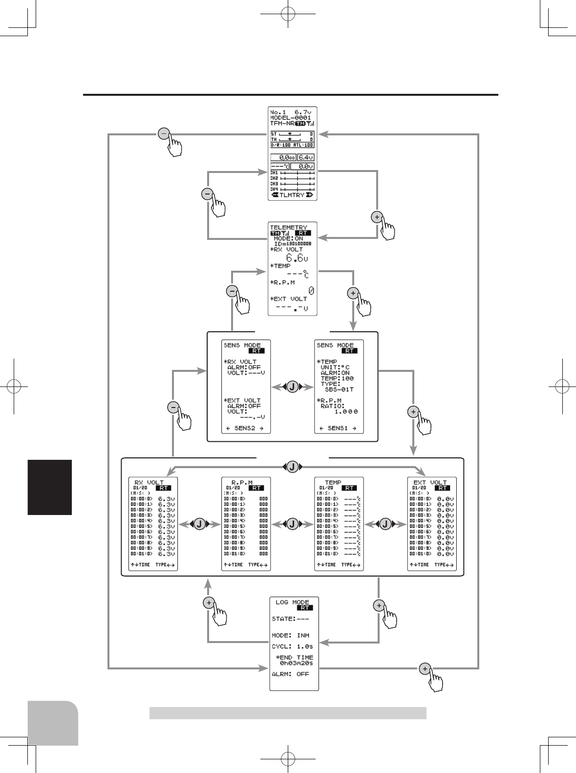
Telemetry "TELEMETRY"
Telemetry/Log Screen Map
Function ON/OFF (MODE)
INH, ACT
Select button
- Select with the (+) or (-) but-
tons.
Telemetry function :OFF- Telemetry function :ON
- Receiver ID before setting or ID mis-
match.
- When the receiver ID is set, before
ID check in the receiver power OFF
state.
- Telemetry function :ON
- Receiver ID setting complete.
- Data receiving sensitivity display.
- shows that data cannot be received be-
cause it is outside the data receiving range or
because of the effects of an obstruction or the
receiver power is OFF after receiver ID check.
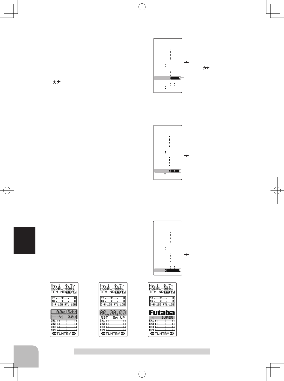
Receiver -> Transmitter:
The reception strength is shown.
The reception strength
No signal reception
High
Low
Telemetry turned ON, LED of
the jog key will blink twice.
117
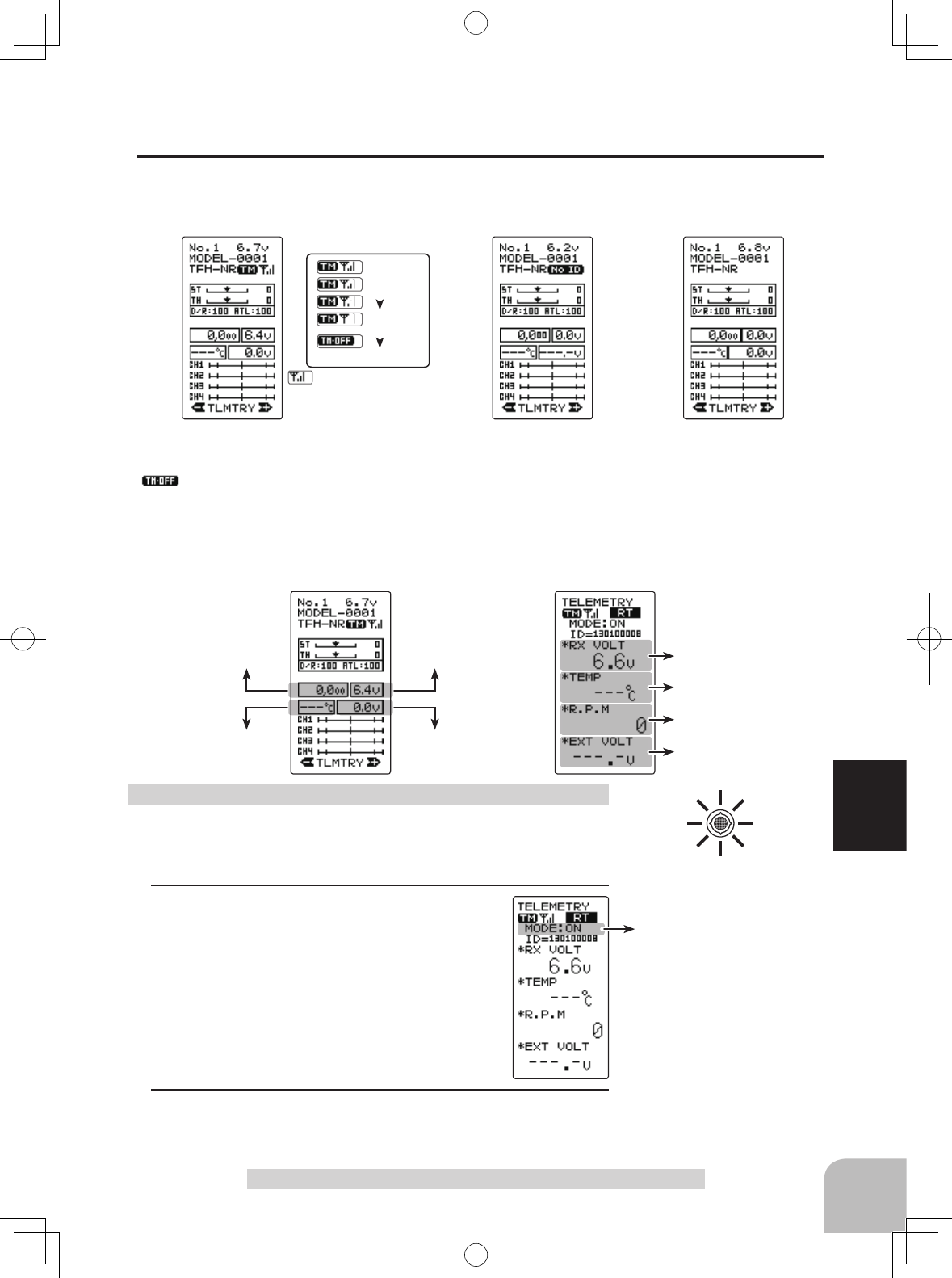
Function
Telemetry "TELEMETRY"
(HOME screen)
Temperature Sensor info
RPM Sensor info Receiver voltage info
Voltage Sensor info
(TELEMETRY ON/OFF screen)
Temperature Sensor info
RPM Sensor info
Receiver voltage info
Voltage Sensor info
Telemetry Function ON/OFF
The telemetry data can be viewed at the HOME screen and telemetry ON/OFF screen.
The telemetry function can also be turned on and off at the telemetry ON/OFF screen.
The telemetry ON/OFF and communication status can be checked at the HOME screen.
Refer to the map on page 116 for the telemetry ON/OFF (telemetry) screen display.
(Preparation)
- On the HOME screen, open the TELEMETRY ON/OFF
screen by pressing the (+) button.
1Select the setting item "MODE" using the
(JOG) button up or down operation. Set the
function by pressing the (+) or (-) button.
"OFF" : Function OFF
"ON" : Function ON
2When completed, move the cursor to [RT] by the (JOG) but-
ton, and return to the HOME screen by pressing the (JOG)
button.
Telemetry function ON/OFF
Alarm
ON/OFF
ON, OFF
- Select with the (+) or (-) but-
tons.
Voltage alarm
3.8V~8.0V
Initial value: 5V
Adjust button
- Adjust with the (+) and (-) but-
tons.
- Return to the initial value "0" by
pressing the (+) and (-) buttons
simultaneously for about 1 sec-
ond.
118
Function
Telemetry "TELEMETRY"
Receiver power sup-
ply voltage setting
External power
supply Voltage
sensor setting
Page1
Temperature sensor
setting
RPM sensor setting
Page2
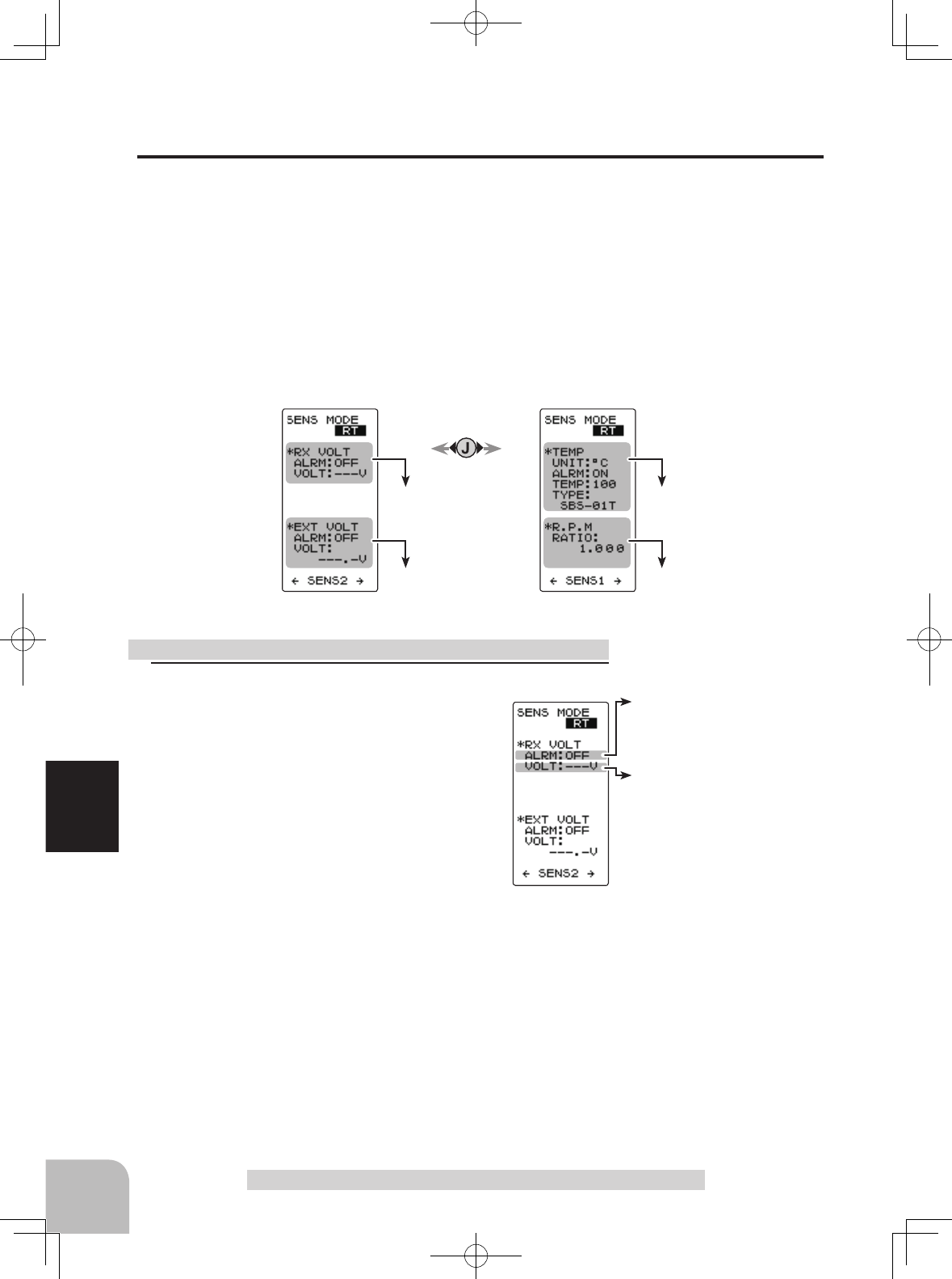
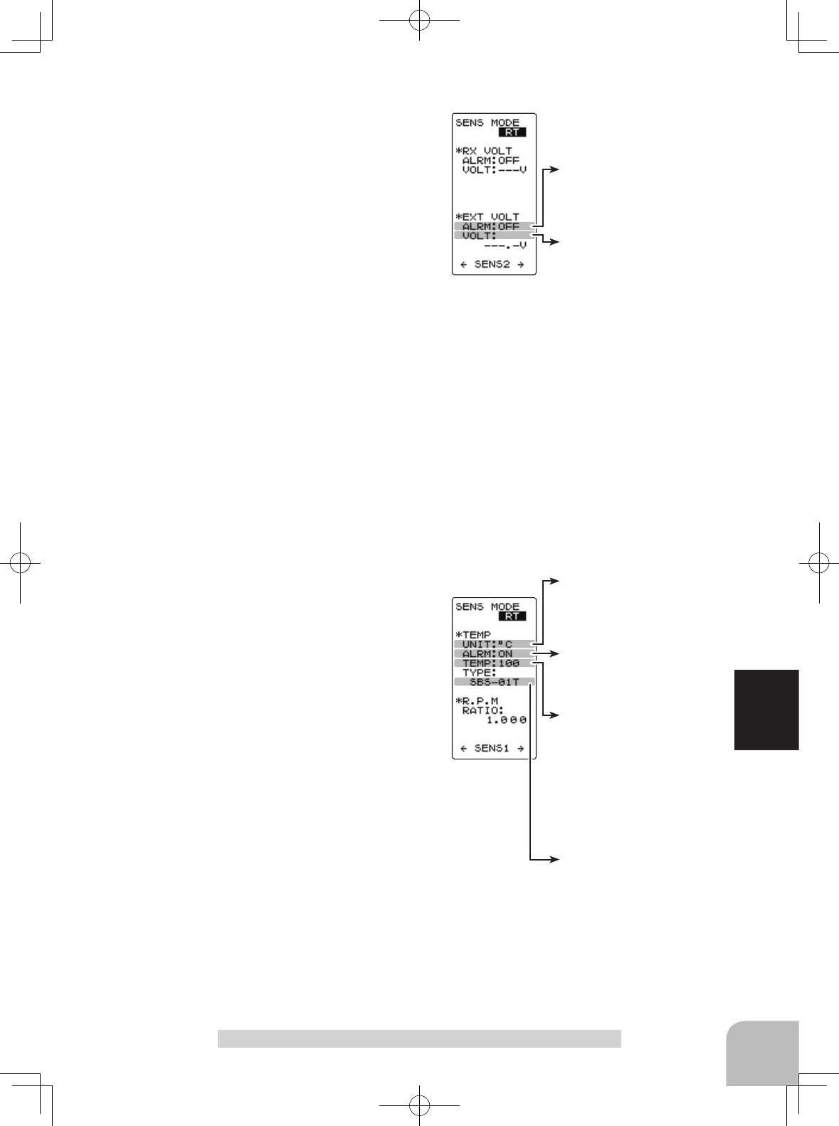
Telemetry Sensor Setting
An audible alarm can be generated by the T4GRS from the data from a telemetry sen-
sor. This setting sets alarm ON/OFF and the alarm conditions.
Refer to the map on page 116 for the sensor setting (SENS MODE) screen display.
There are receiver power source (battery) voltage and external power source (drive bat-
tery) voltage settings on page 1 of the sensor setting screen and temperature and speed
settings on page 2. Pages 1 and 2 are switched by (JOG) button left or right operation.
(Setting of each item)
Setting the receiver power supply voltage alarm
Display page 1 using (JOG) button left or right
operation.
Select "ALRM" of the "*RX VOLT" setting
items using (JOG) button up or down opera-
tion, and set alarm ON/OFF with the (+) but-
ton or (-) button.
"OFF" : Alarm OFF
"ON" : Alarm ON by a voltage drop below the specified voltage
Select "VOLT" of the "*RX VOLT" setting items using (JOG)
button up or down operation, and set the voltage at which
the alarm begins to sound with the (+) button or (-) button.
The number of digits can be shifted using (JOG) button left
or right operation.
When completed, move the cursor to [RT] using the (JOG)
button, and return to the HOME screen by pressing the (JOG)
button twice.
Setting method
Alarm
ON/OFF
ON, OFF
- Select with the (+) or (-) but-
tons.
Voltage alarm
0.0V~90.0V
Initial value: 5V
Adjust button
- Adjust with the (+) and (-) but-
tons.
- Return to the initial value "0" by
pressing the (+) and (-) buttons
simultaneously for about 1 sec-
ond.
Sensor type
SBS-01T, Temp 125
Select button
- Select with the (+) or (-) but-
tons.
Display type
°C, °F
- Select with the (+) or (-) but-
tons.
Alarm
ON/OFF
ON, OFF
- Select with the (+) or (-) but-
tons.
Temperature alarm
-20~200°C/ -4~392°F
Initial value: 200°C/ 212°F
Adjust button
- Adjust with the (+) and (-) but-
tons.
- Return to the initial value "0" by
pressing the (+) and (-) buttons
simultaneously for about 1 sec-
ond.
119
Function
Telemetry "TELEMETRY"
Setting external power supply voltage alarm
Display page 1 using (JOG) button left or right
operation.
Select "ALRM" of the "EXT VOLT" setting
items using (JOG) button up or down opera-
tion, and set alarm ON/OFF with the (+) but-
ton or (-) button.
"OFF" : Alarm OFF
"ON" : Alarm ON by a voltage drop below the specified voltage
Select "VOLT" of the "*EXT VOLT" setting items using (JOG)
button up or down operation, and set the voltage at which
the alarm begins to sound with the (+) button or (-) button.
The number of digits can be shifted using (JOG) button left
or right operation.
When completed, move the cursor to [RT] using the (JOG)
button, and return to the HOME screen by pressing the (JOG)
button twice.
Setting the temperature alarm
Display page 2 using (JOG) button left or right operation.
Select "UNIT" of the "*TEMP" setting items using (JOG) but-
ton up or down operation, and select Celsius or Fahrenheit
temperature display with the (+) button or (-) button.
"°C" : Celsius display
"°F" : Fahrenheit
Select "ALRM" of the "*TEMP" setting items
using (JOG) button up or down operation, and
set alarm ON/OFF with the (+) button or (-)
button.
"OFF" : Alarm OFF
"ON" : Alarm ON at the specified temperature
Select "TEMP" of the "*TEMP" setting items using (JOG)
button up or down operation, and set the temperature at
which the alarm begins to sound with the (+) button or (-)
button. Select "TYPE" of the "*TEMP" setting items using
(JOG) button up or down operation, and set the type of
sensor with the (+) button or (-) button
"SBS-01T" : Option sensor
"Temp 125" : Option sensor for Europ
When completed, move the cursor to [RT] by the (JOG) but-
ton, and return to the HOME screen by pressing the (JOG)
button twice.
Function ON/OFF (MODE)
INH, ACT
- Select with the (+) or (-) but-
tons.
Gear ratio (moderating ratio)
0.001~64
Initial value: 1
Adjust button
- Adjust with the (+) and (-) but-
tons.
- Return to the initial value "0" by
pressing the (+) and (-) buttons
simultaneously for about 1 sec-
ond.
120
Function
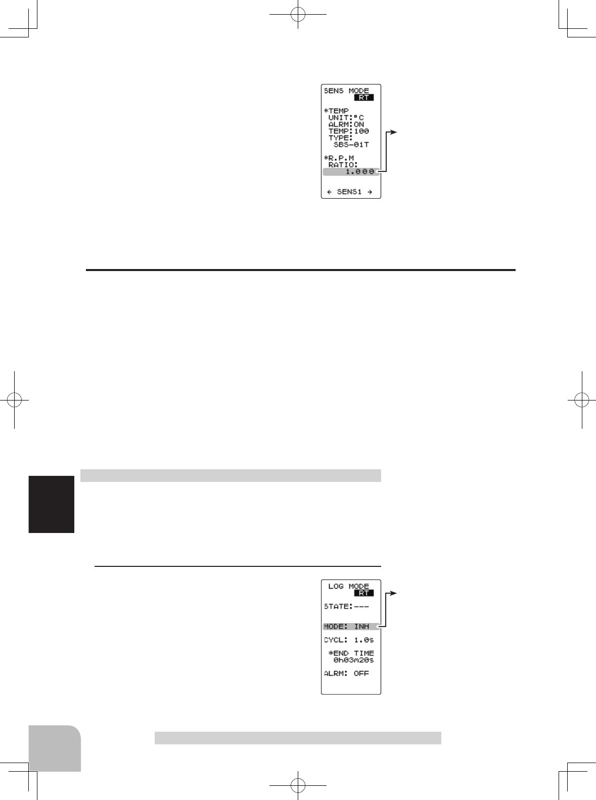
Telemetry "TELEMETRY"
Setting the gear ratio
Display page 2 using (JOG) button left or right
operation. Select "RATIO" of the "R.P.M" set-
ting items using (JOG) button up or down op-
eration, and set the location the sensor is to
actually measure and the gear ratio of the mo-
tor and engine with the (+) button or (-) button.
There is no alarm function.
When completed, move the cursor to [RT] using the (JOG)
button, and return to the HOME screen by pressing the (JOG)
button twice.
Log Setting Start/Stop
The data from a telemetry sensor can be saved to the T4GRS as a data log. Since the
data is sequentially updated, when data logging is performed, the old data is erased.
Only 1 data is saved.
The interval at which the data is acquired can be selected from a minimum 0.1 second
to a maximum 60 seconds. Because the maximum count is 200, if the count is made 200
counts at 0.1 second intervals, 20 seconds worth of data is acquired, and if the count is
made 200 counts at 60 second intervals, 3 hours 20 minutes worth of data is acquired.
Data logging is started and stopped by setting SW1 set by SW/Dial function to "LOG-
GER" and by switch (SW1). If the switch (SW1) is not set, data logging is started by
throttle stick from the log setting screen.
Data logging can also be started by throttle stick from this screen and stopped by switch
(SW1) set by SW/dial function.
Refer to the map on page 116 for the log setting (LOG MODE) screen display.
(Preparation)
When using a switch (SW1) to start and stop data logging,
set SW1 to "LOGGER" by SW/dial function.
- On the HOME screen, open the LOG MODE screen by
pressing the (-) button.
1 (Log function ON/OFF)
Move the cursor to the "MODE" setting item
using (JOG) button up or down operation, and
turn on the log function by setting "MODE" to
"ACT" by pressing the (+) button or (-) button.
If "MODE" is not set to "ACT", the log function
will not be performed even if the switch etc, is
operated.
"INH" : Function OFF
"ACT" : Function ON
Log setting method
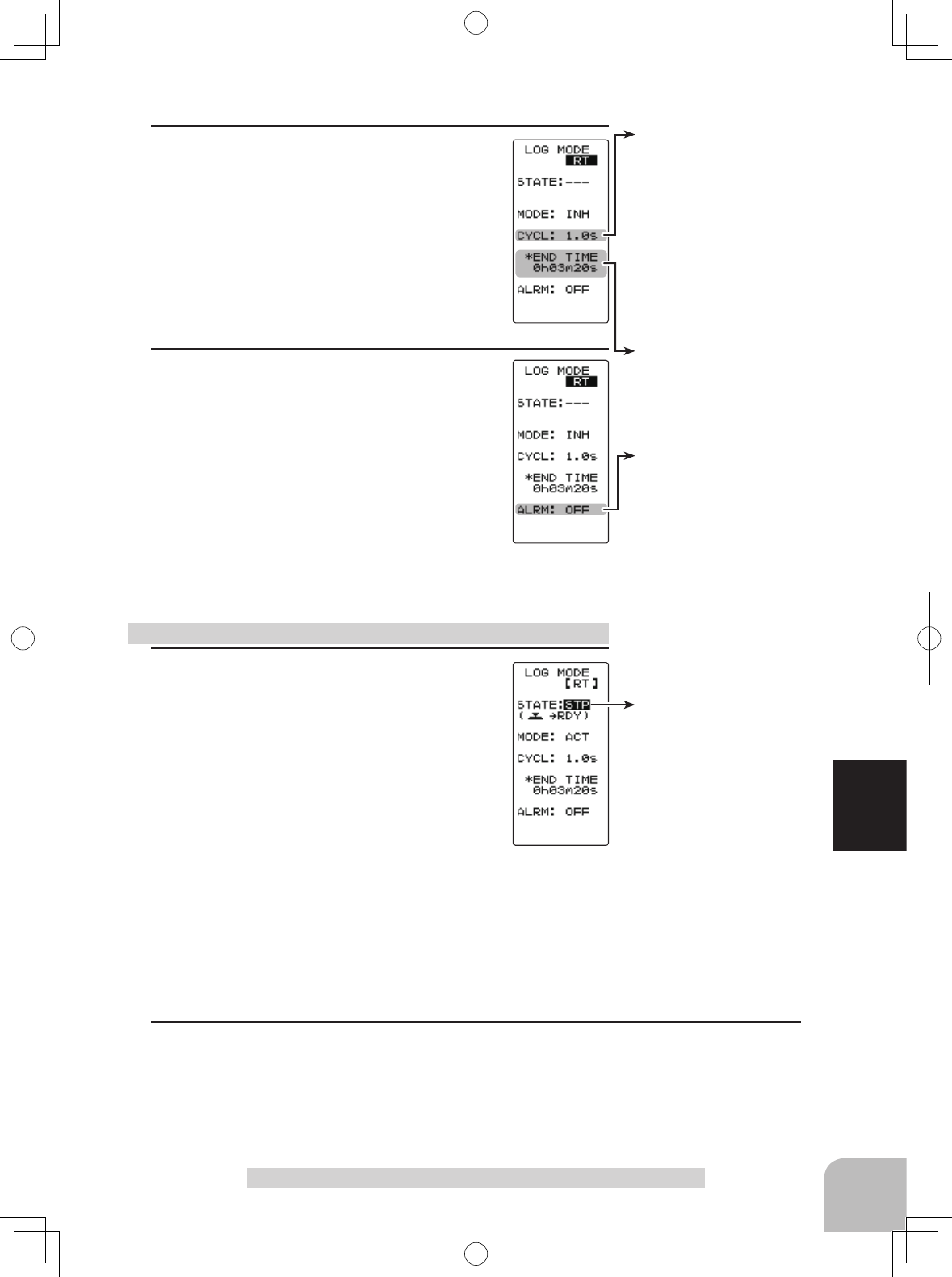
Log recording cycle
0.1~60s(sec)
0.1~10s(sec)0.1s step
10s~60s(sec)1s step
Initial value: 1.0sec
Adjust button
- Adjust with the (+) and (-) but-
tons.
- Return to the initial value "0" by
pressing the (+) and (-) buttons
simultaneously for about 1 sec-
ond.
Log recording time
20s (seconds)~3h 20m (3
hours 20 minutes)
The maximum recordable time
set by CYCL is displayed auto-
matically.
Status display
RDY :
Throttle stick operation wait
STA :Logger running
STP : Logger stopped
Alarm
ON/OFF
ON, OFF
- Select with the (+) or (-) but-
tons.
121
Function
Telemetry "TELEMETRY"
1 (Log start operation)
-Start by switch (SW1)
When the switch (SW1) set by SW/dial func-
tion is pressed, data logging starts.
-Starting by throttle stick
Display the log setting (LOG MODE) screen
and select the "STATE" setting item using
(JOG) button up or down operation, and press
the (JOG) button for approximately 1 second.
Log function start/stop operation
2 (Recording cycle setting)
Select the "CYCL" setting item using (JOG)
button up or down operation, and set the data
acquisition interval from a minimum 0.1 sec-
ond to a maximum 60 seconds with the (+)
button or (-) button.
The maximum recordable time set by CYCL is
displayed at END TIME shown below.
3 (Count alarm ON/OFF)
Select the "ALRM" setting item using (JOG)
button up or down operation. To sound an
electronic beep at each log count, set "ALRM"
to ON with the (+) button or (-) button.
"OFF" : Alarm OFF
"ON" : Alarm ON at each log count
When completed, move the cursor to [RT] using the (JOG)
button, and return to the HOME screen by pressing the (JOG)
button twice.
An electronic beeping sound is generated and the "STATE" display switches from "RST"
to blinking "RDY", and the logger enters the stick operation wait state. When the stick
is operated in the forward direction, data logging begins. (STATE display "STA") When
the end time arrives, an electronic beep sounds and data logging stops. To return to the
HOME screen during data logging, move the cursor to [RT] using (JOG) button up or
down operation, and press the (JOG) button or (+) button.
2 (Log forced end)
To abort logging, press the switch (SW1), in the same way as starting, or display the log
setting (LOG MODE) screen and select the "STATE" setting item using (JOG) button up
or down operation and press the (JOG) button for approximately 1 second. An electronic
beeping sound is generated and logging is stopped.
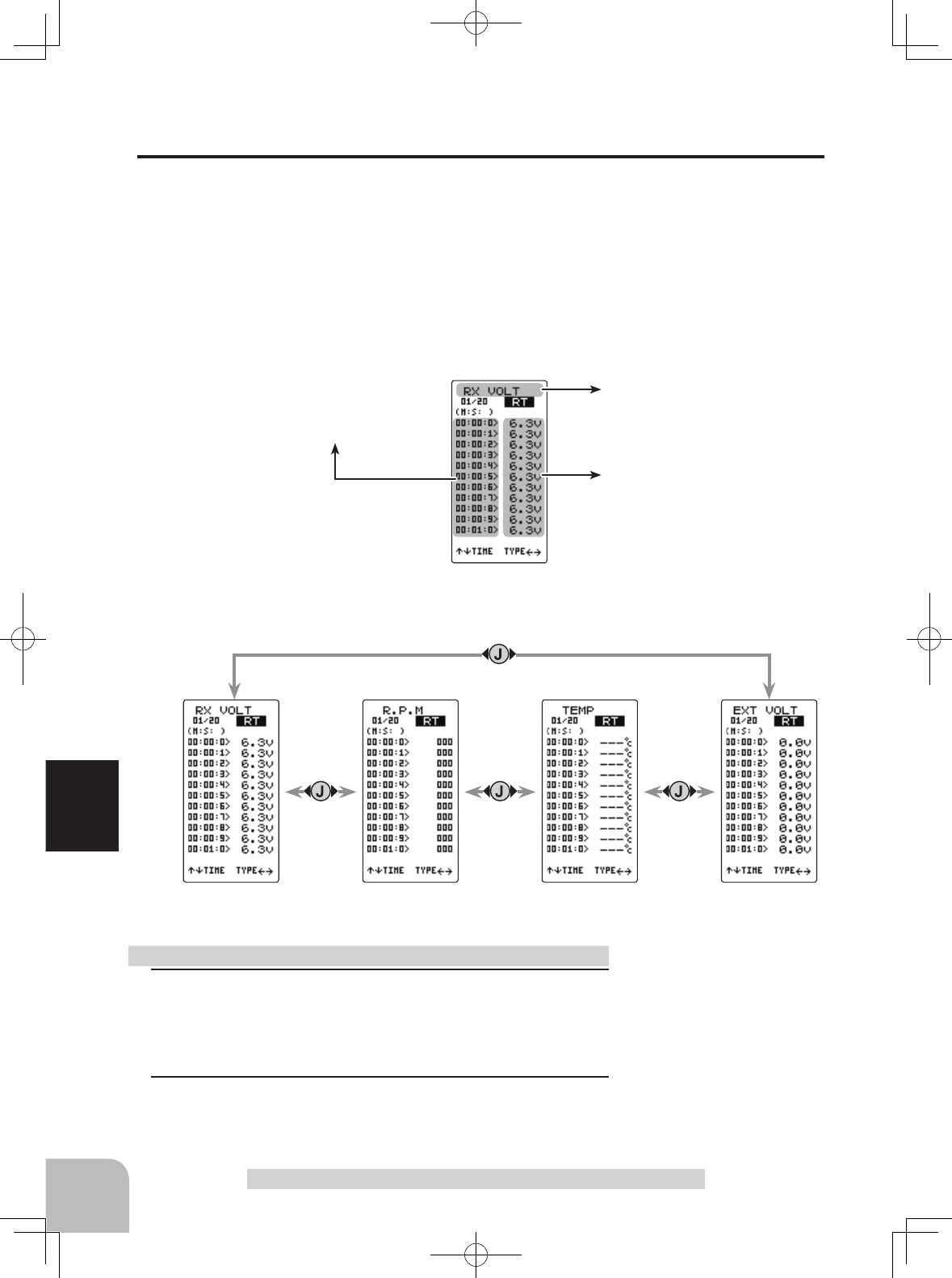
122
Function
Telemetry "TELEMETRY"
Displays the log data elapsed time.
Displays the type of log data.
Displays the data
Receiver power supply voltage.
Receiver power supply voltage log.
Receiver power supply
voltage log
External power sup-
ply voltage log
Temperature sensor log RPM sensor log
1(Log memory check)
Each time the (JOG) button is operated up or down the list is
scrolled 10 counts and each log data can be checked up to
200 counts.
2 When completed, return to the HOME screen by pressing
the (JOG) button.
Log list check method
Log Data List
The log data list can be called up when checking the log data memorized by logging op-
eration .
The maximum log data is up to 200 counts.
Refer to the map on page 116 for the log list screen.
Example: Receiver power supply voltage log list screen.
Refer to the below map for the display method of each log list screen.
123
Reference
Reference
Ratings
*Specications and ratings are subject to change without prior notice.
Caution
Communication method:One-way operation system
Maximum operating range:100m (Optimum condition)
For safety: F/S, B-F/S, ID
Transmitter T4GRS-2.4G
(T-FHSS/S-FHSS/FHSS system, 2 stick type, 4 channels)
Transmitting frequency:
2.4GHz band
Power requirement:
AA Dry cell batteries x 4 (6V)
Current drain:
150mA or less
Transmission antenna:
1/2λ di-pole
Receiver R304SB: (T-FHSS system, 4 channels)
Power requirement:
4.8V~7.4V battery / 3.5 ~ 8.4V useable
(Dry cell battery cannot be used.)
Receiving frequency:
2.4GHz band
System:
T-FHSS system (auto detection)
Size:
1.38x0.91x0.33" (35.1x23.2x8.5mm)(excluding a projection part)
Weight: 0.23oz. (6.6g)
When using the T4GRS in the T-FHSS (HIGH) and S-FHSS (HIGH) mode, always use it under
the following conditions:
Servos :
Futaba digital servo (including BLS Series brushless servos)
Receiver’s battery :Matched to the ratings of the receiver and connected digital servo (dry cell battery cannot be used).
Transmitter mode :
RX MODE
Under other conditions, the set will not operate, or the specified performance will not be displayed even if it operates.
In addition, it may cause servo trouble. Futaba will not be responsible for damage, etc. caused by combination with the
products of other companies.
In addition, the FSU Fail Safe Unit cannot be used because the system is different. Use the fail safe function of the trans-
mitter.
When using analog servos, always switch the T4GRS servo response to the "NORM" mode.
Transmitter mode
:"
T-FHSS(NORM)", "T-FHSS(NORM)"and FHSS mode .
Receiver’s battery :Matched to the ratings of the receiver and connected servo (dry cell battery cannot be used).
The set cannot operate in the "HIGH" mode. Operation in this mode will cause trouble with the servo and other equipment.
Digital servos (including BLS Series brushless servos) can also be used in the "NORM" mode.
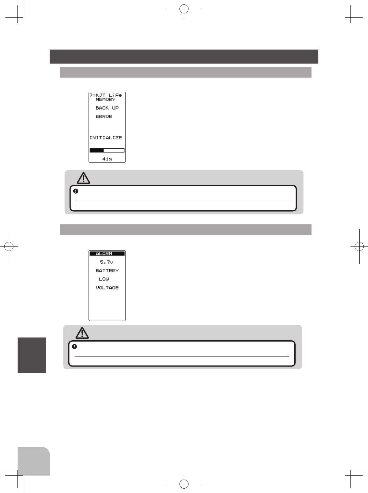
124
Reference
Warning Displays
Low Battery Alarm
If the transmitter battery voltage drops to 4.1V(when us-
ing Futaba rechargeable type battery: 4.9V) or less, an
audible alarm will sound and "BATTERY LOW VOLT-
AGE" will be displayed on the LCD screen.
LCD screen:
Audible alarm:
Continuous tone.
Warning
When a low battery alarm is generated, cease operation immediately and retrieve the
model.
If the battery goes dead while in operation, you will lose control.
Power supply and low battery alarm
The T4GRS can use an optional rechargeable battery. However, the battery alarm setting
is different from that of the dry cell battery (alkaline battery recommended). Therefore,
always set the battery type to match the power source used. Always set the battery type
to "N5/L2" especially when using a Futaba rechargeable type battery. If the set is used
at "DRY4" setting, the time from low battery alarm to system stopping will become ex-
tremely short.
Backup Error
If the data is lost for an unknown reason, an audible
alarm will sound and "MEMORY BACK UP ERROR"
will be displayed on the LCD screen.
LCD screen:
Audible alarm:
Tone will sound (9 times), then repeat.
Warning
When a backup error is generated, immediately stop using the system and request
repair from the Futaba Service Center.
If you continue to use the system, the transmitter may malfunction and cause loss of control
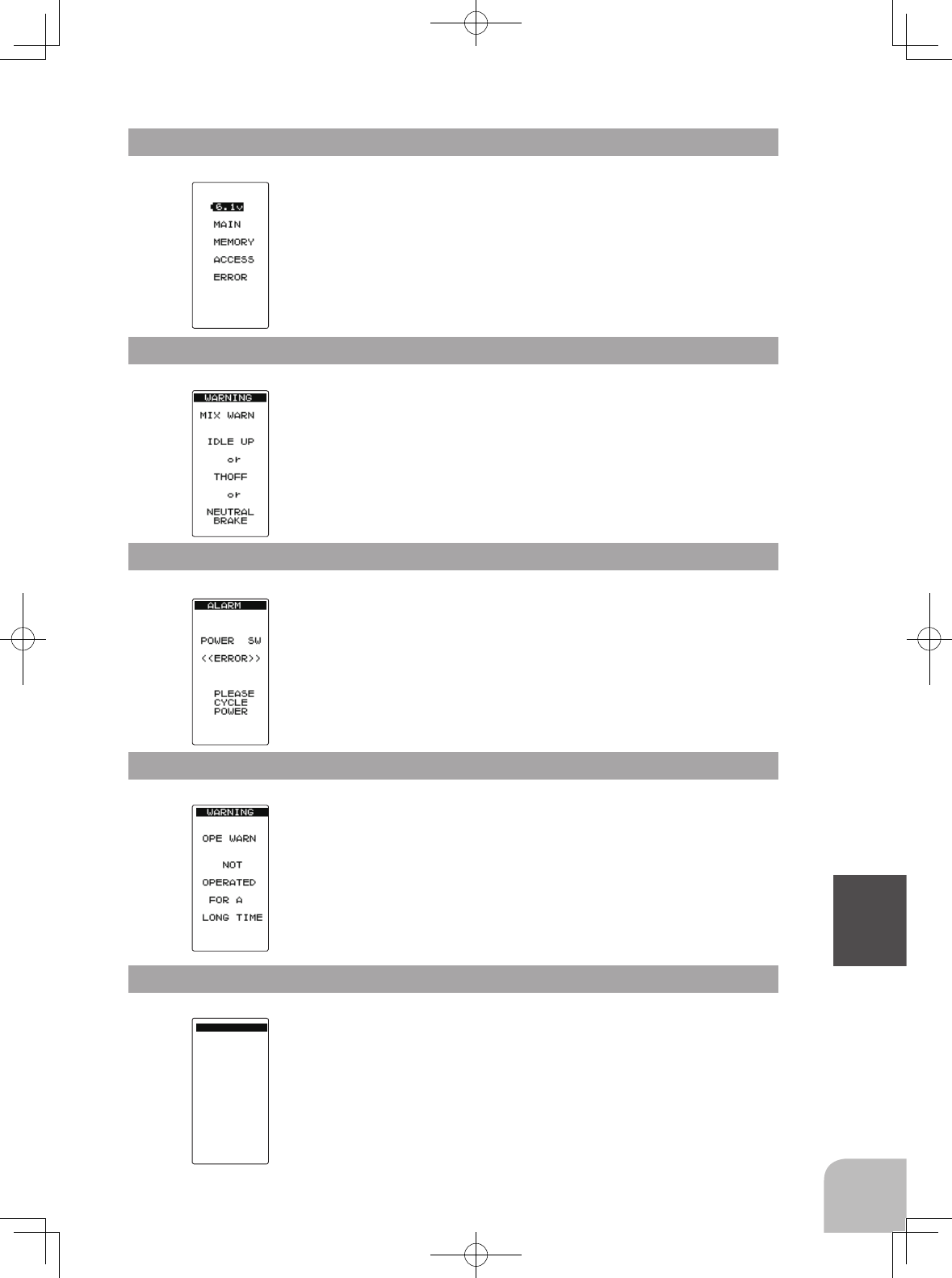
THROTTLE
STICK
RX セッテイ
WARNING
If the power switch is quickly switched from the DISP
mode to the PW ON mode or vice versa, the switch er-
ror shown at the left may be generated. If this occurs,
cycle the power.
LCD screen:
125
Reference
Power off forgotten warning
Throttle stick warning
If the T4GRS is not operated for 10 minutes, an audible
alarm is sounded and "OPE WARN" is displayed on the
screen. The audible alarm stops when the steering stick,
throttle stick, and any dial, switch, or edit button is op-
erated. If you are not going to use the transmitter, turn
the power off.
If the transmitter is switched on with the throttle stick
above the slow position and alarm will sound. The
alarm will stop when the stick is moved to the slow po-
sition. Ensure that the throttle stick is in the slow posi-
tion when the transmitter is switched on.
Audible alarm:
Tone sounds (7 times) and stops (repeated)
Audible alarm:
Tone sounds (7 times) and stops (repeated)
LCD screen:
LCD screen:
MIX Warning
MIX Warning
When the power switch is turned on while the idle-up,
preset (engine cut) or neutral brake function switch is on,
an audible alarm will sound and "MIX WARN" will be
displayed on the LCD. When that function switch is turned
off, the alarm will stop.
LCD screen:
Audible alarm:
Tone sounds (7 times) and stops (repeated)
Audible alarm:
Tone sounds (7 times) and stops (repeated)
Memory Error
If the data in the transmitter is not transferred normally
when the power is turned on, an audible alarm will
sound and "MAIN MEMORY ACCESS ERROR" will
be displayed on the LCD.
- To stop the alarm, turn off the power.
- Turn the power back on. If the alarm is not generated again, there
is no problem.
LCD screen:
Audible alarm:
Tone sounds (7 times) and stops (repeated)
*This function only operates when in "TH-STK : F10" mode.

Optional Parts
126
Reference
The following parts are available as 4GRS options. Purchase them to match your appli-
cation. For other optional parts, refer to our catalog.
Transmitter Battery
When purchasing a transmitter battery use the following:
Part name
HT5F1800B (6V/1800mAh) NiMH battery
FT2F1700V2(6.6V/1700mAh)/2100BV2 (6.4V/2100mAh) LiFe battery
Please do not use the transmitter batteries HT5F1800B and
FT2F1700V2/2100BV2
as the
receiver's battery.
Since the transmitter's battery has an overload protection circuit, the output power will be
shut down when the high current load is applied. This may result in runaway or fatal crash.
Temperature Sensor (SBS-01T)
RPM Sensor (SBS-01RM)
Voltage Sensor (SBS-01V)
When requesting repair
Before requesting repair, read this manual again and recheck your system. Should the
problems continue, continue as follows.
(Information needed for repair)
Describe the problem in as much detail as possible and send the letter along with the
system in question.
- Symptom (Including the conditions and when the problem occurred)
- R/C System (Send transmitter, receiver and servos)
- Model (Type of model, brand name and model number or kit name)
- Detailed packing list (Make a list of all items sent in for repair)
- Your name, postal and e-mail address and telephone number.
(Warranty)
Read the Warranty card.
- When requesting warranty service, send the card or some type of dated proof pur-
chase.

©Copyright 2014. No part of this manual may be reproduced in any form without prior permission. The contents of this manual are subject
to change without prior notice. While this manual has been carefully written, there may be inadvertent errors or omissions. Please contact
our service center if you feel that any corrections or clarifications should be made.
FUTABA CORPORATION Phone: +81 475 32 6982, Facsimile: +81 475 32 6983
1080 Yabutsuka, Chosei-mura, Chosei-gun, Chiba 299-4395, Japan
©FUTABA CORPORATION 2014, 09 (1)
Federal Communications Commission Interference Statement (for U.S.A.)
This equipment has been tested and found to comply with the limits for a Class B digital
device, pursuant to Part 15 of the FCC Rules. These limits are designed to provide rea-
sonable protection against harmful interference in a residential installation.
This equipment generates, uses and can radiate radio frequency energy and, if not in-
stalled and used in accordance with the instructions, may cause harmful interference to
radio communications. However, there is no guarantee that interference will not occur
in a particular installation. If this equipment does cause harmful interference to radio
or television reception, which can be determined by turning the equipment off and on,
the user is encouraged to try to correct the interference by one or more of the following
measures:
--Reorient or relocate the receiving antenna.
--Increase the separation between the equipment and receiver.
--Connect the equipment into an outlet on a circuit different from that to which the re-
ceiver is connected.
--Consult the dealer or an experienced radio/TV technician for help.
Compliance Information Statement (for U.S.A.)
This device, complies with part 15 of the FCC Rules. Operation is subject to the follow-
ing two conditions:
(1) This device may not cause harmful interference, and (2) This device must accept any
interference received, including interference that may cause undesired operation.
(3) This module meets the requirements for a mobile device that may be used at separa-
tion distances of more than 20cm from human body. To meet the RF exposure require-
ments of the FCC this device shall not be co-located with another transmitting device.
The responsible party for the compliance of this device is:
Futaba Service Center
3002 N Apollo Drive Suite 1, Champaign, IL 61822 U.S.A
TEL (217)398-8970 or E-mail: support@futaba-rc.com (Support)
CAUTION:
To assure continued FCC compliance:
Any changes or modications not expressly approved by the grantee of this device could
void the user’s authority to operate the equipment.
Exposure to Radio Frequency Radiation
To comply with FCC RF exposure compliance requirements, a separation distance of at
least 20 cm must be maintained between the antenna of this device and all persons. This de-
vice must not be located or operating in conjunction with any other antenna or transmitter.