Futurecom Systems Group ULC DVRSVHF MOBEXCOM DVR VHF User Manual 8F083X03 Rev 1
Futurecom Systems Group ULC. MOBEXCOM DVR VHF 8F083X03 Rev 1
Contents
RF Exposure Booklet

Product Safety and RF Energy Exposure Booklet for
Digital Vehicular Repeater Systems (DVRS)
ATTENTION!
Before using this equipment, please read this booklet which contains
important operating instructions for safe usage, RF energy control and
compliance with exposure limits.
8F083X03 Rev. 1
8F083X03 Rev 1
DVRS - Product Safety and RF Energy Exposure Booklet Page 2 of 6
RF Exposure
ATTENTION!
Changes or modifications not expressly approved by Futurecom Systems Group Inc. could void
the User’s authority to operate the equipment.
ATTENTION!
This radio is intended for use in occupational / controlled conditions, where users have full
knowledge of their exposure and can exercise control over their exposure to meet FCC
limits. This radio device is NOT authorized for general population, consumer, or any other
use.
If this vehicular repeater is used in combination with a separate mobile radio transmitter, it is the
responsibility of the Repeater Operator to ensure that Maximum Permissible Exposure (MPE)
limits are observed at all times during repeater transmissions. The Repeater operator must ensure
at all times that no person comes within the MPE distance from the vehicle body to ensure
compliance with the FCC’s RF energy exposure limits for the general population.
The minimum lateral distance between all possible personnel and the body of the DVRS equipped
vehicle must be as specified in Table 1 (Stand-alone DVR) and Table 2 (DVR interfaced to a
Mobile Radio i.e. DVRS).
Failure to observe the MPE distance exclusion area around the antenna may expose persons
within this area to RF energy above the FCC exposure limit for bystanders (general population).
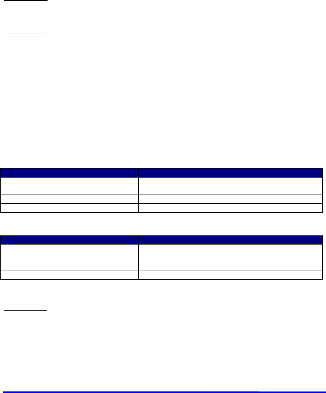
Stand Alone DVR (20W) Recommended Lateral Distance from Vehicle Body
VHF 82cm (50:50 Tx duty)
UHF 403-512MHz 70cm (50:50 Tx duty)
700MHz 73cm
800MHz 76cm
Table 1 Recommended Lateral Distance - Stand Alone DVR
Mobile Radio Rated Power Recommended Lateral Distance from Vehicle Body
DVRS with <7 Watt Mobile Radio 20 cm
DVRS with 7 to 15 Watt Mobile Radio 30 cm
DVRS with 16 to 39 Watt Mobile Radio 60 cm
DVRS with 40 to 100 Watt Mobile Radio 90 cm
Table 2 Recommended Lateral Distance – DVRS (DVR interfaced to a Mobile Radio)
IMPORTANT
The maximum allowed gain of the λ/4 omni-directional antenna for the Mobexcom P25 DVR
Repeater is Unity (0dBd).

8F083X03 Rev 1
DVRS - Product Safety and RF Energy Exposure Booklet Page 3 of 6
RF Exposure Label
The RF Exposure Label should be affixed in the vehicle beside the mobile radio control head.
The label should be in the direct view of the Repeater operator. The label is supplied with the
Mobexcom P25 DVR Repeater.
FCC Label
including interference that may cause undesired
2) This device must accept any interference received,
1) This device may not cause harmful interference, and
Operation is subject to the following two conditions:
This device complies with Part 15 of the FCC Rules.
operation.
Transmit Duty Cycle Alert Tones for DVRS
In order to satisfy the FCC’s RF Exposure limits, a maximum transmitting duty factor of 50% over
any 30 minute period should not be exceeded.
The DVRS is equipped with a software algorithm that tracks mobile radio transmission time and
duty factor on a rolling 25 minute basis. If the mobile radio transmit duty factor approaches 50% at
the end of any 25 minute period, then the DVRS will transmit an alert tone over the air to the
listening subscriber radios in order to alert users to cut back on talk time.
8F083X03 Rev 1
DVRS - Product Safety and RF Energy Exposure Booklet Page 4 of 6
Installation Requirements for Compliance with Radio
Frequency (RF) Energy Exposure Safety Standards
ATTENTION!
To ensure compliance with RF Energy Safety Standards:
Install only Futurecom / Motorola approved antennas and accessories and set conducted
power into the DVR and Mobile antennas equal to or lower then the approved power levels –
refer to Table 3 (Stand Alone DVR) or Table 4 (DVR interfaced to a Mobile Radio i.e. DVRS).
Ensure the antenna installation is consistent with the DVR Antenna Installation instructions
described in this document as well as with the Mobile Radio Antenna Installation Instructions
published in the applicable Motorola Installation Manual.
Ensure the Product & RF Safety Booklets enclosed with the Mobile Radio and the DVR are
available to the end user upon completion of the installation.
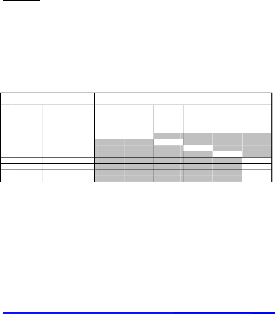
ANTENNA STAND ALONE DVR MODEL
# Kit # Freq.
Range
[MHz] Type 700 MHz
(20W) 800 MHz
(20W) 403-430
(20W) 450-470
(20W) 470-512
(20W) VHF (20W)
1 *HAF4016 764-870 ¼ wave 20W 20W
2 HAE6012A 380-433 ¼ wave 20W
3 HAE4003A 450-470 ¼ wave 20W
4 HAE4004 470-512 ¼ wave 20W
5 HAD4006 136-144 ¼ wave 20W
6 HAD4007 144-150.8 ¼ wave 20W
7 HAD4008 150.8-162 ¼ wave 20W
8 HAD4009 162-174 ¼ wave 20W
Table 3 Approved Stand-Alone DVR Combinations
8F083X03 Rev 1
DVRS - Product Safety and RF Energy Exposure Booklet Page 5 of 6
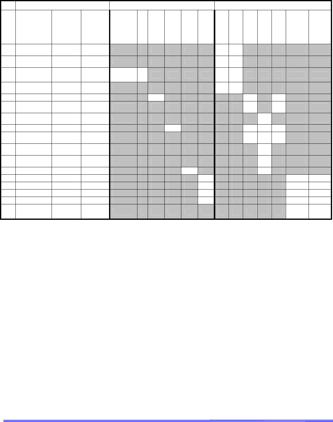
Antenna DVR Band Mobile Radio Band
# Kit # Freq.
Range
[MHz] Type
700 MHz
(20W)
800 MHz
(
20W
)
380-430
(20W)
450-470
(20W)
470-512
(20W)
VHF (20W)
700 MHz
(30W)
800 MHz
(35W)
380-470
(40W)
450-520
(45W)
380-470
(110W)
VHF (50W)
VHF
(110W)
1 HAF4013 764-870 ¼ wave,
3db X X
2 HAF4014 764-870 ¼ wave,
3db X X
3 *HAF4016 764-870 ¼ wave 5W /
12.6W* X X X
4 HAF4017 764-870 ¼ wave,
3db X X
5 HAE6012A 380-433 ¼ wave X X X
6 HAE6013 380-470 ½ wave,
2db X X
7 HAE6016 450-512 Low
wideband X
8 HAE4003A 450-470 ¼ wave X X X X
9 HAE4011 445-470 ½ wave,
3.5db X X X
10 HAE4012 470-495 ½ wave,
3.5db X
11 HAE4013 494-512 ½ wave,
3.5db X
12 HAE4004 470-512 ¼ wave X X
13 HAD4006 136-144 ¼ wave 6W X X
14 HAD4007 144-150.8 ¼ wave 6W 57W 57W
15 HAD4008 150.8-162 ¼ wave 6W 57W 57W
16 HAD4009 162-174 ¼ wave 6W 57W 57W
17 *RAD4010A 136-174 ½ wave X *
120W
Table 4 Approved DVRS Configurations
* DVR RF Power into DVR Antenna HAF4016 can be 12.6W only when used with Mobile Radio equipped with ½
wave length antenna RAD4010A. VHF Mobile radio with RAD4010A can only be used in conjunction with 700MHz
DVR (equipped with HAF4016 antenna).
X – Band Combination not currently FCC Approved.
Empty cells – Unused Configuration.
Non Empty Cells – MPE / SAR compliant power output.
VHF mobiles are limited to 57 Watts and 147-174 MHz when using 1/4 wave antennas.
Due to the ERP limitations enforced by FCC the antenna cables may not be trimmed.

8F083X03 Rev 1
DVRS - Product Safety and RF Energy Exposure Booklet Page 6 of 6
Antenna Installation Instructions
IMPORTANT
To assure optimum performance and compliance with RF Energy Safety standards, these
antenna installation guidelines and instructions are limited to metal-body vehicles with
appropriate ground planes and take into account the potential exposure of back seat
passengers and bystanders outside the vehicle.
Selecting an Antenna Site/Location on a Metal Body Vehicle
External installation
Check the requirements of the antenna supplier and install the vehicle antenna external to a metal
body vehicle in accordance with those requirements.
Roof top
For optimum performance and compliance with RF Energy Safety standards, mount the mobile
radio antenna in the center area of the roof.
Trunk lid
For optimum performance and compliance with RF Energy Safety standards, mount the DVRS
antenna in the center area of the trunk.
Before installing an antenna on the trunk lid:
Ensure that the distance from the antenna location on the trunk lid will be at least 85 cm (33
inches) from the front surface of the rear seat-back to assure compliance with RF Energy
Safety standards.
Ensure that the trunk lid is grounded by connecting grounding straps between the trunk lid and
the vehicle chassis.
Ensure that the antenna cable can be easily routed to the radio. Route the antenna cable as
far away as possible from any vehicle electronic control units and associated wiring.
Check the antenna location for any electrical interference.
Ensure that any other mobile radio antenna on this vehicle is at least 1ft (30.48cm) away from
the DVR and its associated mobile radio antennas.
NOTE:
Any two metal pieces rubbing against each other (such as seat springs, shift levers, trunk and
hood lids, exhaust pipes etc.) in close proximity to the antenna can cause severe receiver
interference.
Mobile Radio / DVR Antenna separation
To ensure interference-free performance when both the Mobile Radio and the DVR are active, the
two antennas must be mounted in such way as to provide 30dB minimum antenna isolation.