Futurecom Systems Group ULC DVRSVHF MOBEXCOM DVR VHF User Manual
Futurecom Systems Group ULC. MOBEXCOM DVR VHF
Contents
User Manual
Futurecom Systems Group Inc.
MOBEXCOM DVRS
VEHICULAR REPEATER
USERS MANUAL
8A083X02 Rev- 2.0

Vehicular Repeater System
Futurecom Systems Group Inc.DVRS Users Manual 8A083X02_VHF_Rev2_0 Rev. Preliminary Page 2
1. TABLE OF CONTENTS
Section Page
1. TABLE OF CONTENTS .....................................................................................................2
Notes, Attentions, Important ........................................................................................................3
REPEATER MODES......................................................................................................................................6
CONTROL HEAD..........................................................................................................................................7
REPEATER RADIO UNIT ............................................................................................................................8
MOBILE RADIO UNIT .................................................................................................................................8
3. OPERATION ........................................................................................................................9
CONTROL HEAD..........................................................................................................................................9
APPENDIX 1................................................................................................................................12
APPENDIX 2................................................................................................................................13

Vehicular Repeater System
Futurecom Systems Group Inc.DVRS Users Manual 8A083X02_VHF_Rev2_0 Rev. Preliminary Page 3
Notes, Attentions, Important
Throughout this manual, you will see Notes, and Attentions, Important
Their meaning is as follows:
NOTE:
A clarifying statement that expands on the text that follows.
IMPORTANT:
An important statement that should be considered and / or implemented in order to achieve
adequate equipment operation.
ATTENTION:
An instruction that must be followed in insure compliance with the appropriate standards or
proper equipment operations.
Vehicular Repeater System
Futurecom Systems Group Inc.DVRS Users Manual 8A083X02_VHF_Rev2_0 Rev. Preliminary Page 4
NOTE:
This equipment has been tested and found to comply with the limits for a Class A digital device, pursuant to Part
15 of the FCC Rules. These limits are designed to provide reasonable protection against harmful interference when the
equipment is operated in a commercial environment. This equipment generates, uses, and can radiate radio frequency energy
and, if not installed and used in accordance with the instruction manual, may cause harmful interference to radio
communications. However, there is no guarantee that interference will not occur in a particular installation.
ATTENTION:
Changes or modifications not expressly approved by Futurecom Systems Group Inc. could void the user’s authority
to operate the equipment.
RF EXPOSURE
ATTENTION:
To satisfy FCC/IC RF exposure requirements for mobile transmitting devices, a separation distance of 82 cm or
more should be maintained between the antenna of this device and persons during 50% TX – 50% RX duty cycle
operation. To ensure compliance, operations at closer than this distance is not allowed.
RADIO OPERATOR:
Futurecom requires the MOBEXCOM DVRS Repeater operator to ensure FCC Requirements for Radio Frequency
Exposure are met. The minimum distance between all possible personnel and an omnidirectional antenna with gain
not greater than 0dBd = 2.15 dBi must be at least 82cm (approximately 32.3”). If MOBEXCOM DVRS is used with
a mobile radio, please refer to Appendix 2 for further instructions.
FAILURE TO OBSERVE THE MPE DISTANCE EXCLUSION AREA AROUND THE ANTENNA MAY
EXPOSE PERSONS WITHIN THIS AREA TO RF ENERGY ABOVE THE FCC EXPOSURE LIMIT FOR
BYSTANDERS (GENERAL POPULATION).IT IS THE RESPONSIBILITY OF THE REPEATER OPERATOR
TO ENSURE THAT MPE LIMITS ARE OBSERVED AT ALL TIMES DURING REPEATER
TRANSMISSIONS. THE REPEATER OPERATOR MUST ENSURE AT ALL TIMES THAT NO PERSON
COMES WITHIN MPE DISTANCE FROM THE ANTENNA.
ATTENTION:
The MOBEXCOM DVRS Repeater must be restricted to occupational use only to satisfy FCC RF Exposure
requirements.
Vehicular Repeater System
Futurecom Systems Group Inc.DVRS Users Manual 8A083X02_VHF_Rev2_0 Rev. Preliminary Page 5
ANTENNA INSTALLATION
IMPORTANT:
The maximum allowed gain of the omni-directional antenna for the MOBEXCOM DVRS Repeater is 0 dBd
(dipole) = 2.15 dBi.
FCC LABELS:
This device complies with Part 15 of the FCC Rules. Operation is subject to the following two conditions:
(1) This device may not cause harmful interference and
(2) This device must accept any interference received, including interference that may cause
undesired operation.
RF EXPOSURE LABEL:
Restricted to occupational use to satisfy FCC RF exposure
limits. See user manual for operating requirements.
RF EXPOSURE LABEL INSTALLATION LOCATION:
IMPORTANT:
The RF Exposure Label should be affixed in the vehicle beside the mobile radio control head. The label should be
in the direct view of the Repeater operator. The label is supplied with the MOBEXCOM DVRS Repeater.

Vehicular Repeater System
Futurecom Systems Group Inc.DVRS Users Manual 8A083X02_VHF_Rev2_0 Rev. Preliminary Page 6
2. INTRODUCTION
The Futurecom MOBEXCOM DVRS® Vehicular Repeater is designed to interface to a range of mobile radios and
control heads. It permits expanded operation of portable radios. The Vehicular Repeater system consists of. a mobile radio,
MOBEXCOM DVRS® Vehicular Repeater unit, a mobile radio Control Head and a RF multiplexer. The Control Head
communicates with the Vehicular Repeater and the mobile using a serial data protocol.
REPEATER MODES
The Vehicular Repeater operates in one of three modes. The mode of operation is selectable from the Mobile Control
Head by the mobile radio operator.
The three modes are known as the MOBILE, LOCAL and SYSTEM modes. The function and purpose of each mode is
described as follows.
Mobile Mode
In the MOBILE mode, the vehicular repeater is completely disabled. The mobile radio is operational and will permit
the mobile radio user to communicate conventionally, using the mobile radio. The mobile user may select the desired
mobile operating channel, adjust the receiver volume level and transmit using the microphone Push-to-Talk (PTT).
This mode is used when Repeater operation is not desired. The Vehicular Repeater System operates similarly to a
standard mobile radio system, as if the Repeater were not present. The RF multiplexer is disabled and the antenna is
connected directly to the mobile radio.
The MOBILE mode should be selected if several Repeater equipped vehicles are in the same area and another
Vehicular Repeater already has LOCAL or SYSTEM mode enabled.
Local Repeat Mode
In the LOCAL repeat mode, the Vehicular Repeater is enabled to permit communications among nearby portable
radio users and the mobile radio user. Repeater signals are not retransmitted by the Mobile Radio, so that
communications on the mobile channel will not be disturbed. However, all functions of the mobile radio operate
normally, except for scan, microphone mobile Push-to-Talk, scan activation, mode selection, zone selection, home
channel operation and mobile channel selection. When the LOCAL repeat mode is selected, the mobile radio scan is
deactivated and the mobile radio reverts to the selected mobile channel. Signals received by the Vehicular Repeater
receiver are heard in the mobile speaker and will also be retransmitted by the Vehicular Repeater transmitter. Signals
received by the Mobile receiver are heard in the Mobile speaker and will be transmitted by the Vehicular Repeater.
When signals are present in both the Vehicular Repeater and Mobile receivers simultaneously, the signal from the
Vehicular Repeater will have priority in the mobile speaker. (Note that the receiver/PTT and speaker priorities are
programmable.)
The mobile user will key only the Vehicular Repeater transmitter when using the microphone Push-to-Talk. The
Vehicular Repeater receiver has full priority over the mobile radio operator microphone Push-to-Talk. To respond to a
mobile signal, the mobile operator must enter either the MOBILE or SYSTEM mode to be able to transmit from the
mobile radio.
The mobile user may adjust the receiver volume level and transmit over the Vehicular Repeater using the
microphone Push-to-Talk.
The LOCAL mode, as the name implies, permits communications among portable radio users and the mobile radio
operator, without interfering with the mobile radio dispatch channels.
System Repeat Mode
In the SYSTEM repeat mode, both the Mobile Radio and the Vehicular Repeater are enabled to permit the full
exchange of communications among nearby portable radio users, the mobile radio user and the dispatcher and other
users on the Mobile Radio channel. Signals received by the Vehicular Repeater receiver are heard in the mobile speaker
and will also be retransmitted by both the Vehicular Repeater and Mobile transmitters. Signals received by the Mobile
receiver are heard in the mobile radio speaker and are also retransmitted out of the Vehicular Repeater transmitter.
However, all functions of the mobile radio operate normally, except for scan, scan activation, mode selection, zone
selection, home channel operation and mobile channel selection. When the SYSTEM repeat mode is selected, the mobile
radio scan is deactivated and the mobile radio reverts to the selected mobile channel. When signals are present in both
the Vehicular Repeater and Mobile receivers simultaneously, the signal from the Vehicular Repeater will have priority in
the mobile speaker. (Note that the receiver/PTT and speaker priorities are programmable.)

Vehicular Repeater System
Futurecom Systems Group Inc.DVRS Users Manual 8A083X02_VHF_Rev2_0 Rev. Preliminary Page 7
The mobile user simultaneously keys both the Mobile radio and Vehicular Repeater transmitters when using the
microphone Push-to-Talk. The Vehicular Repeater receiver has full priority over the mobile radio operator microphone
Push-to-Talk. The mobile radio operator microphone Push-to-Talk has priority over the Mobile receiver.
When signals are present in both the Vehicular Repeater and Mobile receivers simultaneously, the signal from the
Vehicular Repeater has priority in the mobile speaker.
The mobile user may adjust the receiver volume level and transmit over the Vehicular Repeater and Mobile Radio,
using the microphone Push-to-Talk.
The SYSTEM repeat mode is used when full communications among all radio parties is desired.
CONTROL HEAD
The control unit is a standard mobile radio control head. The Vehicular Repeater is designed to operate with a variety of
control heads. It is a ruggedly constructed weatherized control unit, incorporating an array of pushbuttons, a Liquid Crystal
display, 2 knobs and 2 LED indicators. The display and pushbuttons are backlit for night time visibility.
The control unit is housed in a two-piece plastic, weather-resistant housing. The external radio/repeater connections are
made to connector on the rear of the unit. A microphone is provided and is secured to the control unit connector on the front
of the control unit.
A serial-control data interface is used to provide a communications connection between the control unit, the Vehicular
Repeater and the mobile radio.
The following features are provided:
Knobs for:
‘Volume’ with integral Power On/Off pushbutton switch
‘Channel’ selection
Pushbuttons for:
‘Zone’
‘Page’
‘Monitor’ ON/OFF
‘Alarm’ (∆)
‘Private’ (∅)
‘Repeater mode’ selection (H/L)
‘Phon’
‘Scan’
‘Call’
‘Opt’
‘Home Menu’
‘Sel’
LED Indicators for:
‘Mobile Transmit’ (Red LED)
‘Mobile Receiver Busy’ (Orange LED)
Display:
Alphanumeric LCD (with backlighting)
Indicators are provided to display the receiver and transmitter status of the mobile. The ‘Mobile Transmit’ red
indicator lights whenever the mobile transmitter is keyed. The ‘Mobile Receiver Busy’ orange indicator lights whenever the
receiver is busy, regardless of presence or absence of any CTCSS (Channel-Guard) tone coding.

Vehicular Repeater System
Futurecom Systems Group Inc.DVRS Users Manual 8A083X02_VHF_Rev2_0 Rev. Preliminary Page 8
REPEATER RADIO UNIT
The Repeater is designed to implement a Vehicular Repeater System, to provide portable radio users greater
communication range by repeating signals through the vehicle's mobile radio to the dispatch centre. Various modes of
repeater operation are available, to suit different operational requirements. The Vehicular Repeater Radio is the central
connection point for the vehicular system. It connects to an external Control Head and Mobile Radio.
It includes all the necessary hardware for repeater operations. The Repeater is housed in a weather resistant metal
enclosure with 2 removable covers. The covers provide protection for the connectors. The Repeater is mounted on a RF
multiplexer.
The Repeater communicates with the control head and the mobile radio via serial communication bus.
MOBILE RADIO UNIT
The Mobile Radio used in the Vehicular Repeater System is a standard mobile radio. Refer to the mobile radio’s user
manual for details of operation of this radio. The Vehicular Repeater is designed to operate with a variety of mobile radio
units.

Vehicular Repeater System
Futurecom Systems Group Inc.DVRS Users Manual 8A083X02_VHF_Rev2_0 Rev. Preliminary Page 9
3. OPERATION
CONTROL HEAD
The Repeater Control Head selects mode of operation for both the Repeater and the Mobile Radio.
To Turn the Repeater ON or OFF
Press the button in the Volume knob located on the left side of the control unit. The display should become active
when the system turns ON. A test message appears briefly on the display. When the system is turned ON, the Mobile
Channel and Repeater Mode will automatically return to the same settings that were in effect when the power was last
turned OFF. Press the button in the Volume knob second time to turn the Repeater OFF.
To Change the Speaker Volume
Turn the Volume knob until the desired volume level is reached.
To Change the Repeater Mode
Press the 'H/L' button once. The Repeater mode is changed in the following sequence: MOBILE-SYSTEM-
LOCAL-… In the Mobile mode the alphanumeric display shows ‘ZONE CHANNEL’. In the System mode the display
changes to ‘RSYS CHANNEL’ and in the Local mode it shows ‘RLOC CHANNEL’. (‘ZONE’ is the selected Mobile
zone name while ‘CHANNEL’ is the selected Mobile channel name.) When the LOCAL or SYSTEM repeat modes are
selected, the mobile radio scan is deactivated and the mobile radio reverts to the selected mobile channel.
NOTE
The Mobile zone and channel cannot be changed while in LOCAL and SYSTEM repeat
modes.
Refer to the earlier description of repeat modes.
MOBILE XMIT Status Indicator
The 'MOBILE XMIT' red LED indicator is one of two status indicators that is provided on the Control Head,
located in the upper left corner. This indicator will light whenever the Mobile Transmitter is keyed. This will occur in
'MOBILE' or 'SYSTEM' mode when the microphone Push-to-Talk is being pressed or when a signal from the Vehicular
Repeater is being retransmitted by the Mobile Radio (In 'SYSTEM' mode).
MOBILE BUSY Status Indicator
The 'MOBILE BUSY' orange LED indicator is one of two status indicators that are provided on the Control Head,
located in the upper left corner. This indicator will light whenever the Mobile Radio is receiving any signal on the
selected Mobile Channel. If CTCSS (Channel Guard) tone coding is used, the signal may not be audible if the coding
does not match.
Note that if the microphone is “off-hook”, the Mobile/Repeater audio will be heard on the speaker even if CTCSS is
not present or is incorrect. This is the same as the Monitor function.
ALPHANUMERIC Status Indication
The ‘ZONE’ is not displayed in the LOCAL and SYSTEM repeat modes. Instead, this portion of the alphanumeric
display shows the status of the Repeater in these two modes together with 'MOBILE XMIT' and 'MOBILE BUSY' status
indicators.
The following tables summarize indicators for different Repeater states:
Vehicular Repeater System
Futurecom Systems Group Inc.DVRS Users Manual 8A083X02_VHF_Rev2_0 Rev. Preliminary Page 10
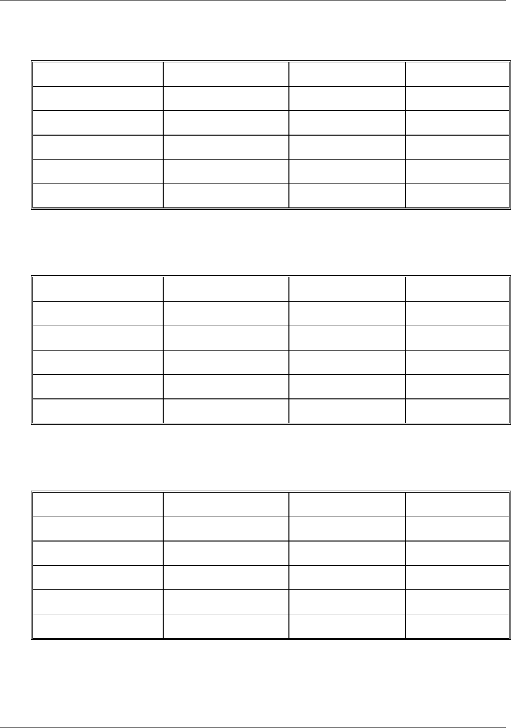
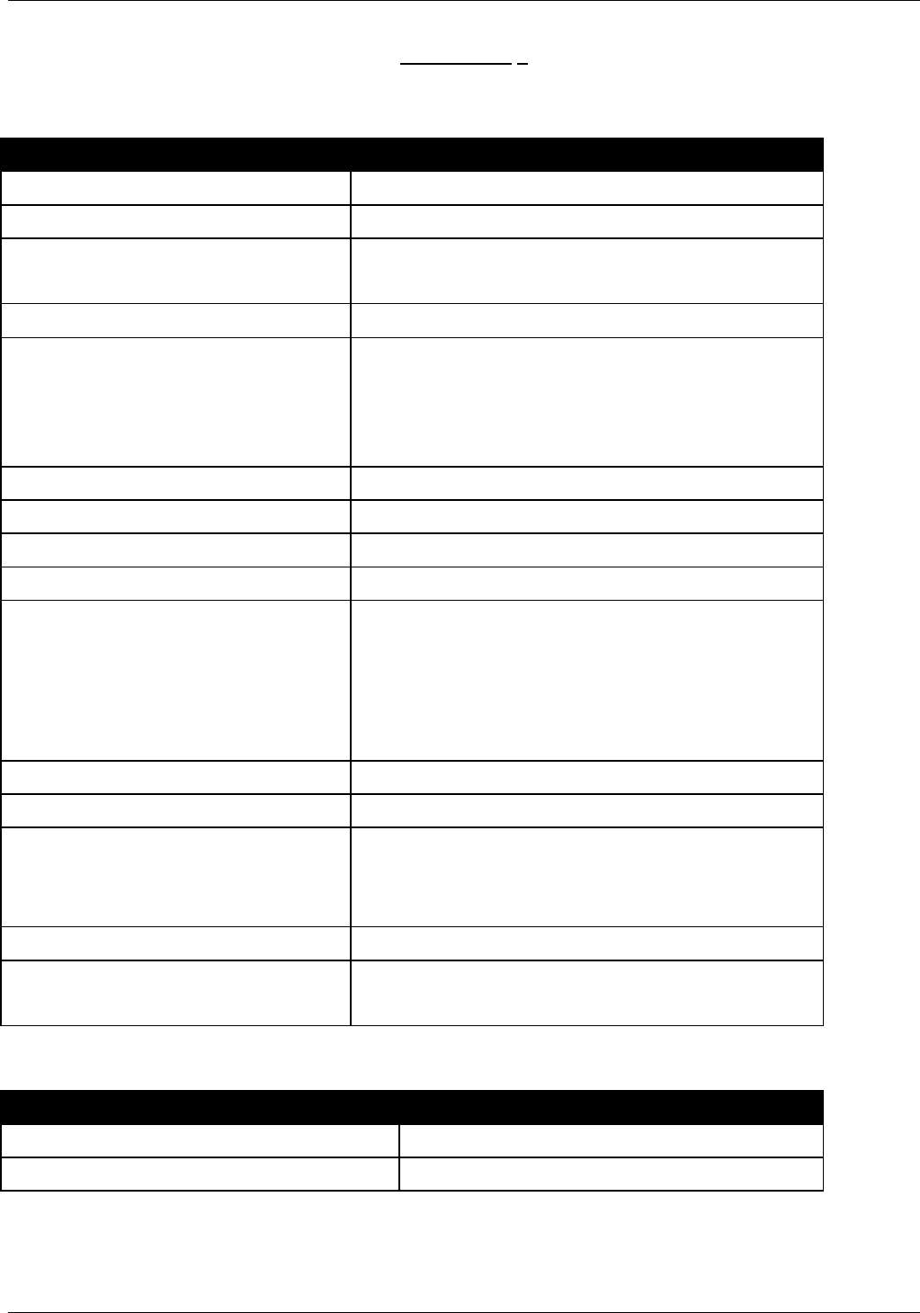
CONTROL HEAD INDICATORS AND ALPHANUMERIC DISPLAY – MOBILE MODE
REPEATER STATE
‘MOBILE BUSY’ ‘MO BILE XMIT’ DISPLAY
MOBILE RECEIVE WITH
CTCSS ON
‘ZONE CHANNEL’
MOBILE RECEIVE
WITHOUT CTCSS ON
‘ZONE CHANNEL’
MICROPHONE PTT ON
‘ZONE CHANNEL’
REPEATER RECEIVE
WITH CTCSS ‘ZONE CHANNEL’
REPEATER RECEIVE
WITHOUT CTCSS ‘ZONE CHANNEL’
CONTROL HEAD INDICATORS AND ALPHANUMERIC DISPLAY – LOCAL MODE
REPEATER STATE
‘MOBILE BUSY’ ‘MO BILE X MIT’ DISPLAY
MOBILE RECEIVE WITH
CTCSS ON ‘RL TX CHANNEL’
MOBILE RECEIVE
WITHOUT CTCSS ON ‘RLOC CHANNEL’
MICROPHONE PTT ‘RL TX CHANNEL’
REPEATER RECEIVE
WITH CTCSS ‘RL RT CHANNEL’
REPEATER RECEIVE
WITHOUT CTCSS ‘RL RX CHANNEL’
CONTROL HEAD INDICATORS AND ALPHANUMERIC DISPLAY – SYSTEM MODE
REPEATER STATE
‘MOBILE BUSY’ ‘MO BILE X MIT’ DISPLAY
MOBILE RECEIVE WITH
CTCSS ON ‘RS TX CHANNEL’
MOBILE RECEIVE
WITHOUT CTCSS ON ‘RSYS CHANNEL’
MICROPHONE PTT ON ‘RS TX CHANNEL’
REPEATER RECEIVE
WITH CTCSS ON ‘RS RT CHANNEL’
REPEATER RECEIVE
WITHOUT CTCSS ‘RS RX CHANNEL’
Note that ‘ZONE’ and ‘CHANNEL’ are the selected Mobile zone and channel names, respectively.

Vehicular Repeater System
Futurecom Systems Group Inc.DVRS Users Manual 8A083X02_VHF_Rev2_0 Rev. Preliminary Page 11
Functions Disabled in LOCAL and SYSTEM Repeat Modes
There are several control unit button and knob functions, which are disabled in the LOCAL and SYSTEM repeat
modes. These are Scan activation, Mode selection, Zone selection, Home channel operation and Mobile channel
selection.
NOTE
A standard audible error signal “bop” as well as an error message is displayed ‘RLOC
VR ACTIVE’ or ‘RSYS VR ACTIVE’ if any of the above functions are attempted in the
LOCAL or SYSTEM repeat modes.
Other Button and Knob Functions
The available Repeater functions are:
• ‘Monitor’ - unmutes speaker audio when Mobile or Repeater RF carrier is present.
• ‘H/C’ - changes Repeat mode of operation.
• ‘Call’ - sends call signal via Mobile transmission (SYSTEM and MOBILE mode only).
• ‘Opt’ - dims alphanumeric display.
All other buttons and knobs function as programmed in the standard mobile radio. Please refer to the mobile radio’s
documentation for details of operation.
Vehicular Repeater System
Futurecom Systems Group Inc.DVRS Users Manual 8A083X02_VHF_Rev2_0 Rev. Preliminary Page 12
APPENDIX 1
General Specifications
Dimensions Height / Width / Depth 92mm (3.63”) / 186mm (7.32”) / 315mm ( 12.41”)
Weight 5.2 kg (11.5 lbs) approx.
Channel Spacing 12.5 kHz or 25 kHz
Analog Voice or P25 Modulation
Power Supply 13.8 VDC ± 20%, negative ground only
DC Current Drain Repeater OFF
RPTR Standby
Receive
Transmit
Max. 0.01 A
Max. 0.8 A
Max 1.7 A @ 7.5 W Audio @ 13.8 VDC
Max. 6.0 A @ 20 W RF output at TX Connector
Operating Temperature -30°C to +60°C
Protection Against Liquids IP6 (water jet proof)
RF Connector Impedance 50 Ohms
Duty Cycle 50% TX – 50% RX
External Connectors
RF Connectors
Computer Interface
Mobile Radio
DC Power
TNC female
USB, 9 pin male circular
20 pin male circular
6 pin male circular
Power Output at TX Connector 20 W Max. (programmable per channel from 1 W Min.)
CCT Option 15 sec to 15 min. or disabled
Carrier Frequency Stability
12.5kHz Channel Spacing
25kHz Channel Spacing
± 1.5 ppm, from –30° to +60°C, ambient +25°C reference
± 2.5 ppm, from –30° to +60°C, ambient +25°C reference
Audio Distortion <3%
Frequency Band (TX and RX)
136 - 174 MHz
Applicable Standards Test
MIL-STD 810C,D,E,F For rain, dust and salt atmospheres
MIL-STD 810C,D,E,F For shock and vibration
Vehicular Repeater System
Futurecom Systems Group Inc.DVRS Users Manual 8A083X02_VHF_Rev2_0 Rev. Preliminary Page 13
APPENDIX 2
Refer to this addendum when using your DVRS in a combination with a separate Mobile transmitter.
If this vehicular repeater is used in combination with a separate mobile radio transmitter, it is the responsibility
of the Repeater Operator to ensure that MPE limits are observed at all times during Repeater transmissions.
The Repeater Operator must ensure at all times that no person comes within the MPE distance from the vehicle
body to ensure compliance with the FCC's RF energy exposure limits for the general population.
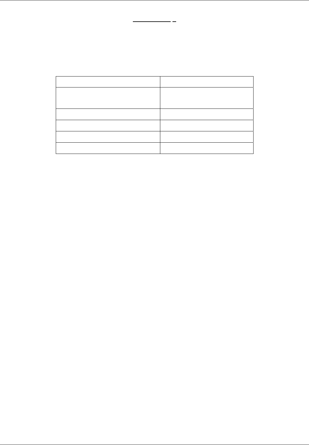
Table 1: Recommended Lateral Distance
Installation Configurations
(Mobile Radio Rated Power)
Recommended Lateral
Distance from Vehicle Body
DVRS with <7 Watt Mobile Radio 20 cm
DVRS with 7 to 15 Watt Mobile Radio 30 cm
DVRS with 16 to 39 Watt Mobile Radio 60 cm
DVRS with 40 to 110 Watt Mobile Radio 90 cm
Antenna Installation Instructions:
IMPORTANT NOTE: To assure optimum performance and compliance with RF Energy
Safety standards, these antenna installation guidelines and instructions are limited to
metal-body vehicles with appropriate ground planes and take into account the potential
exposure of back seat passengers and bystanders outside the vehicle.
Selecting an Antenna Site/Location on a Metal Body Vehicle
1. External installation – Check the requirements of the antenna supplier and install the
vehicle antenna external to a metal body vehicle in accordance with those requirements.
2. Roof top – For optimum performance and compliance with RF Energy Safety standards,
mount the mobile radio ½ λ antenna in the center area of the roof.
NOTE: If using a 1/4 λ mobile antenna, the mobile power must be limited to 57 Watts, and the
DVRS is limited to 5 Watts conducted power into DVRS antenna.
Also, the specific Motorola Mobile radios tested with the DVRS are approved under
FCC ID: AZ492FT3806 and FCC ID: AZ492FT3808.
3. Trunk lid – For optimum performance and compliance with RF Energy Safety standards,
mount the DVRS antenna in the center area of the trunk.
Before installing an antenna on the trunk lid,
- Be sure that the distance from the antenna location on the trunk lid will be at least 85 cm
(33 inches) from the front surface of the rear seat-back to assure compliance with RF
Energy Safety standards.
- Ensure that the trunk lid is grounded by connecting grounding straps between the trunk lid
and the vehicle chassis.
4. Ensure that the antenna cable can be easily routed to the radio. Route the antenna cable as
far away as possible from any vehicle electronic control units and associated wiring.
5. Check the antenna location for any electrical interference.

Vehicular Repeater System
Futurecom Systems Group Inc.DVRS Users Manual 8A083X02_VHF_Rev2_0 Rev. Preliminary Page 14
6. Ensure that any other mobile radio antenna on this vehicle is at least one foot (30.48 cm)
away from the DVRS and mobile radio antenna.
NOTE: Any two metal pieces rubbing against each other (such as seat springs, shift
levers, trunk and hood lids, exhaust pipes, etc.) in close proximity to the antenna can
cause severe receiver interference.