G G Telecom MINI-LIVE Surveillance Camera User Manual Quick start guide LIVE EN FR v1 0
G.G.Telecom Surveillance Camera Quick start guide LIVE EN FR v1 0
Users Guide
Quick start guide
v1.0
PINTSPY INTPSPY
Surveillance
camera
LIVE series
Model:
mini-LIVE
mini-LIVE-4G
mini-LIVE-4GV
1-888-779-7646
www.spypoint.com
under Support section
k
L
K
tech@spypoint.com
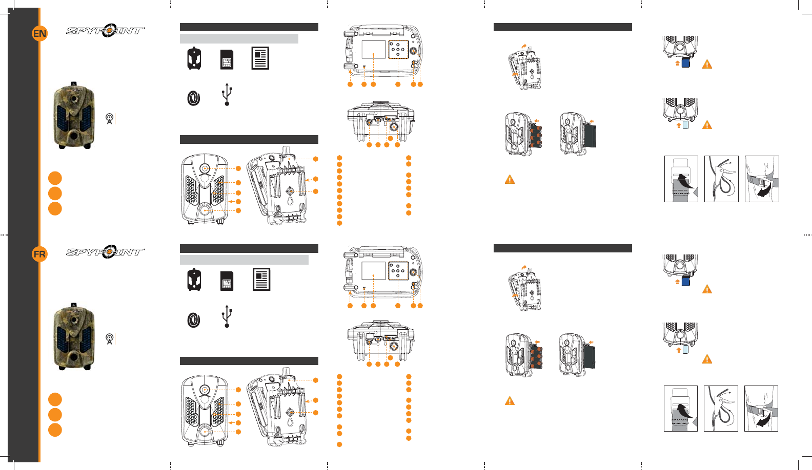
In the box
1
2
3
5
4
6
8
7
Components
Installation
strap USB
cable
Note: Memory card and batteries are sold separately.
Camera Quick start
guide
SIM card*
* mini-LIVE and mini-LIVE-4G only
Included for United-Stated, Canada and United Kingdom only
Navigation buttons
Microphone
(mini-LIVE-4G
and mini-LIVE-4GV)
Power button
12V/Solar panel jack
USB port
SIM card slot (mini-LIVE and
mini-LIVE-4G)
SD card slot
Built-in speaker
(mini-LIVE-4G
and mini-LIVE-4GV)
Photo lens
Invisible LEDs
Test light
Battery case
Detection lens
Mounting bracket
Slot for installation strap
Tripod mount
Cable lock hole
BUSY LED
Viewing screen
1
2
3
4
5
6
7
8
9
10
11
12
910 11 12 13 14
13
14
15 17 1916
18
15
16
17
18
19
3. INSERT THE MEMORY CARD
Insert an SD/SDHC memory card (up to 32
GB capacity) in the card slot, gold contacts
facing up. The card is inserted correctly
when a click is heard.
Before inserting or removing a me-
mory card, always turn off the came-
ra to prevent loss or damage of the photos
already recorded.
4. INSERT THE SIM CARD (MINI-LIVE AND MINI-LIVE-4G)
A SIM card is required to use cellular func-
tions. Carefully insert a SIM card in the card
slot, gold contact area facing down. The card
is inserted correctly when a click is heard.
Before inserting or removing a SIM
card, always turn off the camera.
5. INSTALL THE CAMERA WITH THE SUPPLIED STRAP
Recommended installation height: about 3 feet above the ground.
Do not place the camera facing the sun.
Guide de
démarrage rapide
v1.0
PINTSPY INTPSPY
Caméra de
surveillance
Série LIVE
Modèles :
mini-LIVE
mini-LIVE-4G
mini-LIVE-4GV
1-888-779-7646
www.spypoint.com
sous la section Support
k
L
K
tech@spypoint.com
Dans la boîte
1
2
3
5
4
6
8
7
Composants
Courroie
d'installation Câble
USB
Note: Carte mémoire et piles sont vendues séparément.
Caméra Guide de
démarrage rapide
Carte SIM*
* mini-LIVE et mini-LIVE-4G seulement
Incluse pour les États-Unis, le Canada et Royaume-Uni seulement
Écran de visionnement
Boutons de navigation
Microphone
(mini-LIVE-4G
et mini-LIVE-4GV)
Bouton de mise sous tension
Prise 12V/panneau solaire
Port USB
Fente pour carte SIM
(mini-LIVE et mini-LIVE-4G)
Fente pour carte SD
Haut-parleur
(mini-LIVE-4G
et mini-LIVE-4GV)
Lentille photo
DEL invisibles
Lumière de test
Compartiment à piles
Lentille de détection
Socle
Fente pour courroie
d’installation
Support pour trépied
Ouverture pour câble
cadenas
Lumière BUSY
1
2
3
4
5
6
7
8
9
10
11
12
910 11 12 13 14
13
14
15 17 1916
18
15
16
17
18
19
1. RETIRER LA CAMÉRA DU SOCLE
$3RXVVHUVXUODODQJXHWWHD¿QGHGpJDJHU
la caméra du socle.
B. Retirer la caméra.
2. INSÉRER DES PILES
1RXV UHFRPPDQGRQV O¶XWLOLVDWLRQ GH SLOHV QHXYHV D¿Q
d’assurer un rendement maximal de la caméra. Les piles
AA rechargeables sont déconseillées.
A.
B.
Mise en route 3. INSÉRER UNE CARTE MÉMOIRE
Insérer une carte mémoire de type SD/
SDHC (jusqu’à une capacité de 32 Go) dans
la fente pour carte SD, contacts dorés vers
le haut. La carte est correctement insérée
lorsqu’un clic se fait entendre.
Avant d’insérer ou de retirer une carte
mémoire, toujours mettre la caméra
à OFF pour éviter que les images
présentes sur la carte soient supprimées ou
endommagées.
4. INSÉRER UNE CARTE SIM (MINI-LIVE ET MINI-LIVE-4G)
Une carte SIM est requise pour les fonctions
cellulaires. Insérer délicatement une carte
SIM dans la fente pour carte SIM, zone de
contacts dorée vers le bas. La carte est cor-
rectement insérée lorsqu’un clic se fait en-
tendre.
Avant d’insérer ou de retirer une carte
SIM, toujours mettre la caméra à OFF.
5. INSTALLER LA CAMÉRA À L’AIDE DE LA COURROIE
FOURNIE
Hauteur d’installation recommandée : environ 1 mètre du sol.
Ne pas installer la caméra face au soleil.
1. REMOVE CAMERA FROM THE MOUNTING BRACKET
A. Push the tab to release the camera from
the mounting bracket.
B. Remove the camera.
2. INSERT THE BATTERIES
We recommend the use of new batteries to ensure a
maximum performance of the camera. Rechargeable AA
batteries are not recommended.
A.
B.
Getting started
Lithium battery pack
LIT-09/LIT-C-8
6 alkaline AA
batteries or
Bloc pile lithium
LIT-09/LIT-C-8
6 piles AA
alcalines ou
E. Set the Transmission mode option (mini-LIVE only).
• mySPYPOINT: The camera communicates with the
mySPYPOINT server to update its status or to send photos
to the user account.
MySPYPOINT subscription is required. Activation pro-
cedure available at spypoint.com/activation.
• MMS: The camera communicates by MMS to update its
status or to send photos. Enter up to 5 different phone
numbers to which the MMS will be sent. The country code
and area code must be entered. One MMS is charged for
each recipient.
A MMS plan is required, available from a compatible
cellular service provider.
• Email: The camera communicates by email to update its
status or to send photos. Enter up to 5 different email
DGGUHVVHVWRZKLFKQRWL¿FDWLRQVZLOOEHVHQW
A data plan is required, available from a cellular ser-
vice provider.
F. Set the Frequency option. Allows the user to choose the
number of synchronizations that the camera performs in a
day.
G. Set the First synch time option. Allows the user to choose at
ZKDWWLPHRIWKHGD\WKHFDPHUDFRPPXQLFDWHVIRUWKH¿UVW
time.
E.g.: If the "Frequency" option is set to 6/day and "First synch
time" at 04:00, the camera performs 6 synchronizations per
GD\DQGVWDUWV¿UVWVHQGLQJDWKKKKKDQG
24 h.
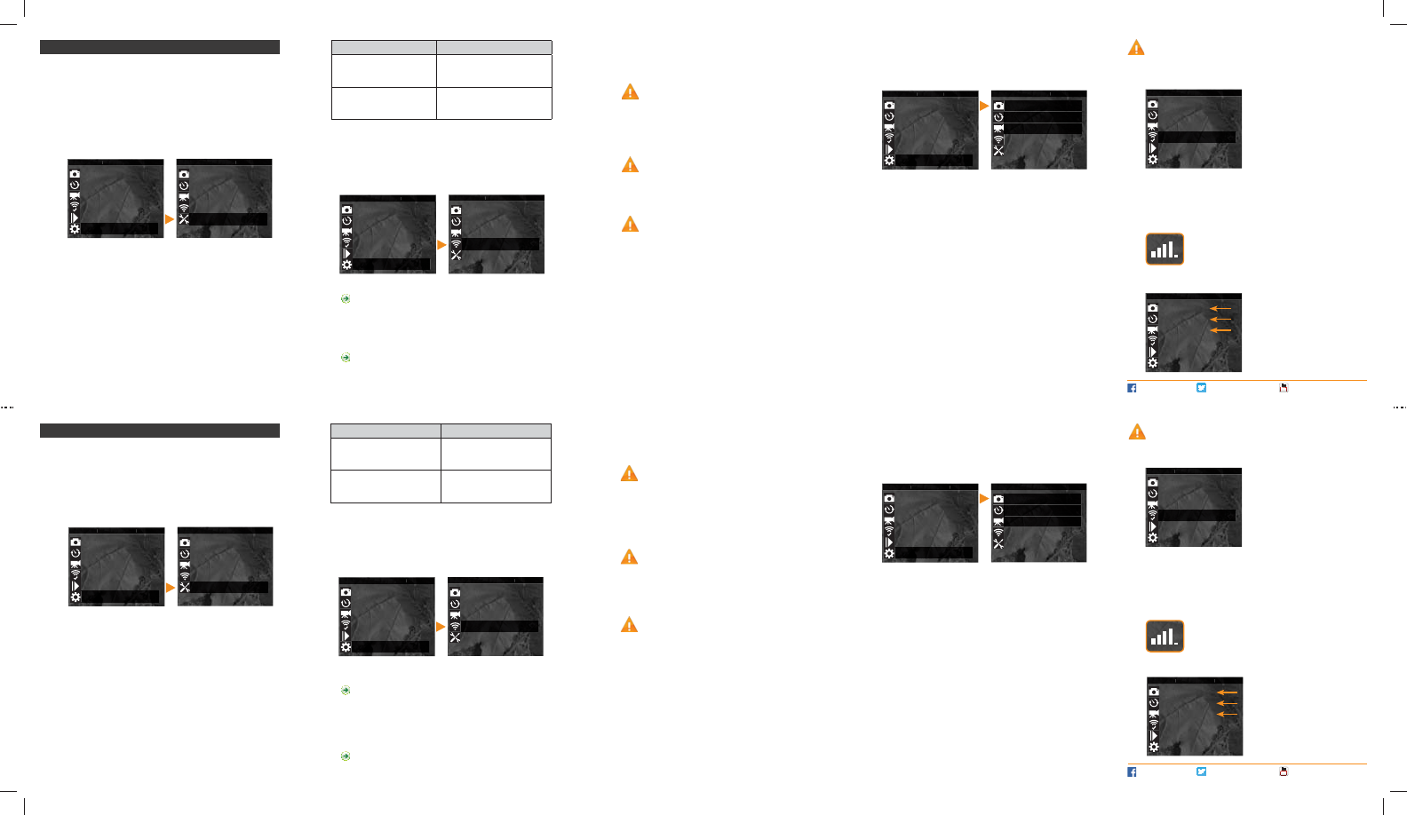
2. CONFIGURE THE WIRELESS SETTINGS
A. In the main menu, select SETTINGS and then, WIRELESS to
access to the Wireless settings menu.
B. Set the Cellular option. Activate this option to send photos by
cellular transmission.
For mini-LIVE-4GV camera, go directly to the F step.
C. Set the Country option. The country where the camera is
used must be selected.
D. Set the Provider option. The provider selected must
correspond with the SIM card used in the camera.
For mini-LIVE-4G camera, go directly to the F step.
Power source LIT-09 charger option
• 6 AA
• 12V
• 12V + 6 AA OFF
• LIT-09*
• 12V + LIT-09*
• Solar panel + LIT-09*ON
* Rechargeable lithium battery pack, sold separately (LIT-09)
or with a charger (LIT-C-8).
Use the K and buttons to navigate in the interface and to change
RSWLRQV8VHWKH2.EXWWRQWRFRQ¿UPDQGWKH2 button to return to
the previous menu.
1. CONFIGURE THE GENERAL SETTINGS
A. Turn on the camera by pressing the power button.
B. In the main menu, select SETTINGS and then GENERAL to
access to the General settings menu.
C. Set the Date (MM/DD/YY or DD/MM/YY).
D. Set the Time (Hour/Minute).
E. Set the Schedule option. This option allows the user to set
the period of operation of the camera for each day of the
week. For a 24 hour operation, the same start and stop times
must be entered as followed (e.g.: 00:00/00:00).
F. Set the LIT-09 charger option depending on the power
source (see next table).
Settings 3. CONFIGURE THE SETTINGS OF THE OPERATING MODE
In the main menu, select SETTINGS and then, PHOTO, TIME
LAPSE or VIDEO to access to the respective operating mode
menu.
PHOTO
Delay: Allows the user to choose the time interval between each
detection before the camera can record the next photo.
Multi-shot: Takes up to 6 consecutive shots at each detection,
with a 10 second delay between each photo.
TIME LAPSE
Interval: This option allows the camera to take photos at regular
preset intervals without detection.
VIDEO
Delay: Allows the user to choose the time interval between each
detection before the camera can record the next video.
Video lenght: Allows the user to select the duration of the
ecording.
3KRWR ¿UVW: When this option is enabled, a photo is taken
immediately before each video.
PERFORM THE STEPS 4 TO 6 DURING THE FINAL
INSTALLATION OF THE CAMERA.
4. TEST THE DETECTION OF THE CAMERA
When the TEST mode is selected,
no photo or video is recorded. Pass
in front of the camera from left to
right. When the camera detects
motion, the test light blinks to
indicate that the camera would
normally have saved a photo or
video. If the system does not
detect the movement, increase
the detection sensitivity using the
SENSITIVITY option in the GENERAL SETTINGS menu or realign
the system differently. In TEST mode, it is possible to take a
photo by pressing the OK button. The photo is saved and appears
in the VIEW mode.
5. VERIFY THE CELLULAR SIGNAL
Still in the TEST mode, make sure to have a cellular
signal. The signal bars are displayed at the top of
the screen.
6. START THE CAMERA
Select the desired operating mode
(photo, time lapse or video) on the
main menu by pressing OK. When
the mode is selected, the test light
LQIURQWRIWKHFDPHUDZLOOÀDVKIRU
60 seconds to allow the user to
leave the area without being pho-
tographed or recorded.
FACEBOOK.COM/SPYPOINT TWITTER.COM/SPYPOINTCAMERA YOUTUBE.COM/SPYPOINTTRAILCAM
Utiliser les boutons K et pour naviguer sur l’interface et changer
d’option, le bouton OK pour sélectionner et le bouton 2 pour retourner
au menu précédent.
1. CONFIGURER LES PARAMÈTRES GÉNÉRAUX
A. Allumer la caméra en appuyant sur le bouton de mise sous
tension.
B. Dans le menu principal, sélectionner CONFIGURATION puis,
*e1e5$/SRXUDFFpGHUDXPHQXGHFRQ¿JXUDWLRQJpQpUDO
C. Régler l'option Date (MM/JJ/AA ou JJ/MM/AA).
D. Régler l'option Heure (Heure/Minute).
E. Régler l'option Période &HWWH RSWLRQ SHUPHW GH FRQ¿JXUHU
la période de fonctionnement de la caméra pour chaque
journée de la semaine. Pour un fonctionnement en tout temps
(période d’opération de 24 heures), les mêmes heures de
début et d’arrêt doivent être programmées (ex.: 00:00/00:00).
F. Régler l'option Chargement LIT-09 en fonction de la source
d'alimentation (voir tableau suivant).
CRQ¿JXUDWLRQ
2. CONFIGURER LES PARAMÈTRES SANS FIL
A. Dans le menu principal, sélectionner CONFIGURATION puis,
6$16),/SRXUDFFpGHUDXPHQXGHFRQ¿JXUDWLRQVDQV¿O
B. Régler l'option Cellulaire. Activer cette option pour que les
photos soient envoyées par transmission cellulaire.
Pour la caméra mini-LIVE-4GV, passer directement à
l'étape
F.
C. Régler l'option Pays. Le pays où la caméra est utilisée doit
être sélectionné.
D. Régler l'option Fournisseur. Le fournisseur sélectionné doit
correspondre à la carte SIM utilisée dans la caméra.
Pour la caméra mini-LIVE-4G, passer directement à
l'étape
F.
Source d'alimentation Option Chargement LIT-09
• 6 AA
• 12V
• 12V + 6 AA Arrêt
• LIT-09*
• 12V + LIT-09*
• Panneau solaire + LIT-09*Marche
* Bloc pile lithium rechargeable, vendu séparément (LIT-09) ou
avec un chargeur (LIT-C-8).
E. Régler l'option Mode transmission (mini-LIVE seulement).
• mySPYPOINT: La caméra communique avec le serveur
mySPYPOINT pour mettre à jour son état ou pour envoyer
des photos sur le compte de l’utilisateur.
Abonnement au service mySPYPOINT requis. Procé-
dure d'activation disponible à spypoint.com/activation.
• MMS: La caméra communique par MMS pour mettre à jour
son état ou pour envoyer des photos. Entrer jusqu'à 5
numéros de téléphone différents vers lesquels les MMS
seront envoyés. Le code de pays ainsi que l'indicatif régional
doivent être entrés. Un MMS est facturé pour chaque
destinataire.
Un forfait MMS est nécessaire, disponible auprès d'un
fournisseur cellulaire compatible.
• Email: La caméra communique par courriel pour mettre à
jour son état ou pour envoyer des photos. Entrer jusqu'à 5
DGUHVVHVFRXUULHOGLIIpUHQWHVYHUVOHVTXHOOHVOHVQRWL¿FDWLRQV
seront envoyés.
Un plan data est nécessaire, disponible auprès d'un
fournisseur cellulaire.
F. Régler l'option Fréquence. Permet de choisir le nombre de
synchronisations que la caméra effectue par jour.
G. Régler l'option Première synch à. Permet de choisir à quel
moment de la journée que la caméra communique pour la
première fois.
Ex. : Si l’option «Fréquence» est réglée à 6/Jour et «Première
synch à» à 04:00, le contrôleur effectue 6 synchronisations
par jour et commence son premier envoi à 4 h, puis à 8 h, 12 h,
16 h, 20 h et 24 h.
3. CONFIGURER LES PARAMÈTRES DES MODES
D'OPÉRATION
Dans le menu principal, sélectionner CONFIGURATION puis,
3+2727,0(/$36(RX9,'e2SRXUDFFpGHUDXPHQXGHFRQ¿JX
ration du mode respectif.
PHOTO
Délai : Permet de choisir l’intervalle de temps avant que la
caméra ne détecte à nouveau et puisse enregistrer la prochaine
photo.
Multi-photos : Permet de prendre jusqu’à 6 photos consécutives
à chaque détection, avec un délai de 10 secondes entre chaque
photo.
TIME LAPSE
Intervalle : Permet la prise de photos à intervalles réguliers
SUpGp¿QLV VDQV TX¶LO \ DLW SRXU DXWDQW XQH GpWHFWLRQ GH
mouvement.
VIDÉO
Délai : Permet de choisir l’intervalle de temps avant que la
caméra ne détecte à nouveau et puisse enregistrer la prochaine
vidéo.
Durée vidéo3HUPHWGHFRQ¿JXUHUODGXUpHG¶HQUHJLVWUHPHQW
des séquences vidéo.
Photo prévidéo : Lorsque cette option est activée, une photo
est prise immédiatement avant chaque vidéo.
EFFECTUER LES ÉTAPES 4 À 6 PENDANT
L'INSTALLATION FINALE DE LA CAMÉRA.
4. TESTER LA DÉTECTION DE LA CAMÉRA
Lorsque le mode TEST est sélec-
tionné, aucune photo ou vidéo n’est
enregistrée. Passer devant la caméra
de façon perpendiculaire. Lorsque la
caméra détecte un mouvement, la
lumière de test clignote pour indi-
quer que la caméra aurait normale-
ment enregistré une photo ou une
vidéo. Si le système ne détecte
pas les mouvements, augmenter la
sensibilité de détection à l’aide de l’option «Sensibilité» située
dans le menu de CONFIGURATION GÉNÉRALE. Réaligner le
système peut aussi être nécessaire. En mode TEST, il est possible
de prendre une photo en appuyant sur le bouton OK. La photo est
enregistrée et apparaît dans le mode VISIONNEMENT.
5. VÉRIFIER LE SIGNAL CELLULAIRE
Toujours dans le mode TEST, s'assurer d'avoir un
VLJQDOFHOOXODLUH/HVEDUUHVGHVLJQDOVRQWDI¿FKpHV
en haut de l'écran.
6. DÉMARRER LA CAMÉRA
Sélectionner le mode d'opération
désiré (photo, time lapse ou vidéo)
dans le menu principal en appuy-
ant sur OK. Lorsque le mode est
sélectionné, la lumière de test sur
le devant de l’appareil clignote du-
rant 60 secondes pour permettre à
l’utilisateur de quitter les lieux sans
rWUHSKRWRJUDSKLpRX¿OPp
FACEBOOK.COM/SPYPOINT TWITTER.COM/SPYPOINTCAMERA YOUTUBE.COM/SPYPOINTTRAILCAM
Photo
Time lapse
Video
Test
View
Settings
MAIN MEN
MAIN MEN
MAIN MEN
MAIN MENU
EIN
EIN
EIN
EIN
Photo
Time lapse
Video
Wireless
General Photo
Time lapse
Video
Test
View
Settings
MAIN MEN
MAIN MEN
MAIN MEN
MAIN MENU
EINEIN
EIN
EIN
Photo
Time lapse
Video
Wireless
General
Photo
Time lapse
Video
Test
View
Settings
MAIN MEN
MAIN MEN
MAIN MENU
MAIN MEN
EIN
EIN
EIN
EIN
Photo
Time lapse
Video
Wireless
General
Photo
Time lapse
Video
Test
View
Settings
MAIN MEN
MAIN MEN
MAIN MENU
MAIN MEN
Photo
Time lapse
Video
Test
View
Settings
MAIN MEN
MAIN MEN
MAIN MENU
MAIN MEN
Photo
Time lapse
Vidéo
Test
Visionnement
&RQ¿JXUDWLRQ
MENU IN
MENU INMENU IN
MENU IN
IA
I
I
NIUA
NIUA
NIUA
NIUA
IN
Photo
Time lapse
Vidéo
6DQV¿O
Général Photo
Time lapse
Vidéo
Test
Visionnement
&RQ¿JXUDWLRQ
MENU INMENU INMENU IN
MENU IN
IA
I
I
NIUA
NIUA
NIUA
NIUA
IN
I
Photo
Time lapse
Vidéo
6DQV¿O
Général
Photo
Time lapse
Vidéo
Test
Visionnement
&RQ¿JXUDWLRQ
MENU IN
MENU INMENU IN
MENU IN
IA
I
I
NIUANIUA
NIUA
NIUA
IN
Photo
Time lapse
Vidéo
6DQV¿O
Général
Photo
Time lapse
Vidéo
Test
Visionnement
&RQ¿JXUDWLRQ
I
I
I
I
CI
C
CI
CI
Photo
Time lapse
Vidéo
Test
Visionnement
&RQ¿JXUDWLRQ
MENU IN
MENU IN
MENU IN
MENU IN
IA
I
I
I

53
Regulation
FCC REGULATIONS
FCC Part l5
This equipment has been tested and found to comply with the limits
for a Class B digital device, pursuant to Part 15 of the Federal
Communications Commission (FCC) rules. These limits are designed to
provide reasonable protection against harmful interference in a residential
installation. This equipment generates, uses and can radiate radio frequen-
cy energy and, if not installed and used in accordance with the instructions,
may cause harmful interference to radio communications. However, there
is no guarantee that interference will not occur in a particular installation.
If this equipment does cause harmful interference to radio or television
reception, which can be determined by turning the equipment o and on,
the user is encouraged to try to correct the interference by one or more of
the following measures:
• Reorient or relocate the receiving antenna.
• Increase the separation between the equipment and receiver.
• Connect the equipment into an outlet on a circuit dierent from
that to which the receiver is connected.
• Consult the dealer or an experienced radio/TV technician for help.
Changes or modications to this equipment not expressly approved by the
party responsible for compliance could void the user’s authority to operate
the equipment.This device complies with Part 15 of the FCC rules. Opera-
tion is subject to the following two conditions: (1) this device may not cau-
se harmful interference, and (2) this device must accept any interference
received, including interference that may cause undesired operation.