G Lufft Mess Und Regeltechnik Gmbh IPS149 2.4 GHz Radar Sensor User Manual Annex No 5
G. Lufft Mess-Und Regeltechnik Gmbh 2.4 GHz Radar Sensor Annex No 5
Manual
Annex No.5
1 of 38
User Manual
2.4 GHz Radar Sensor IPS-149
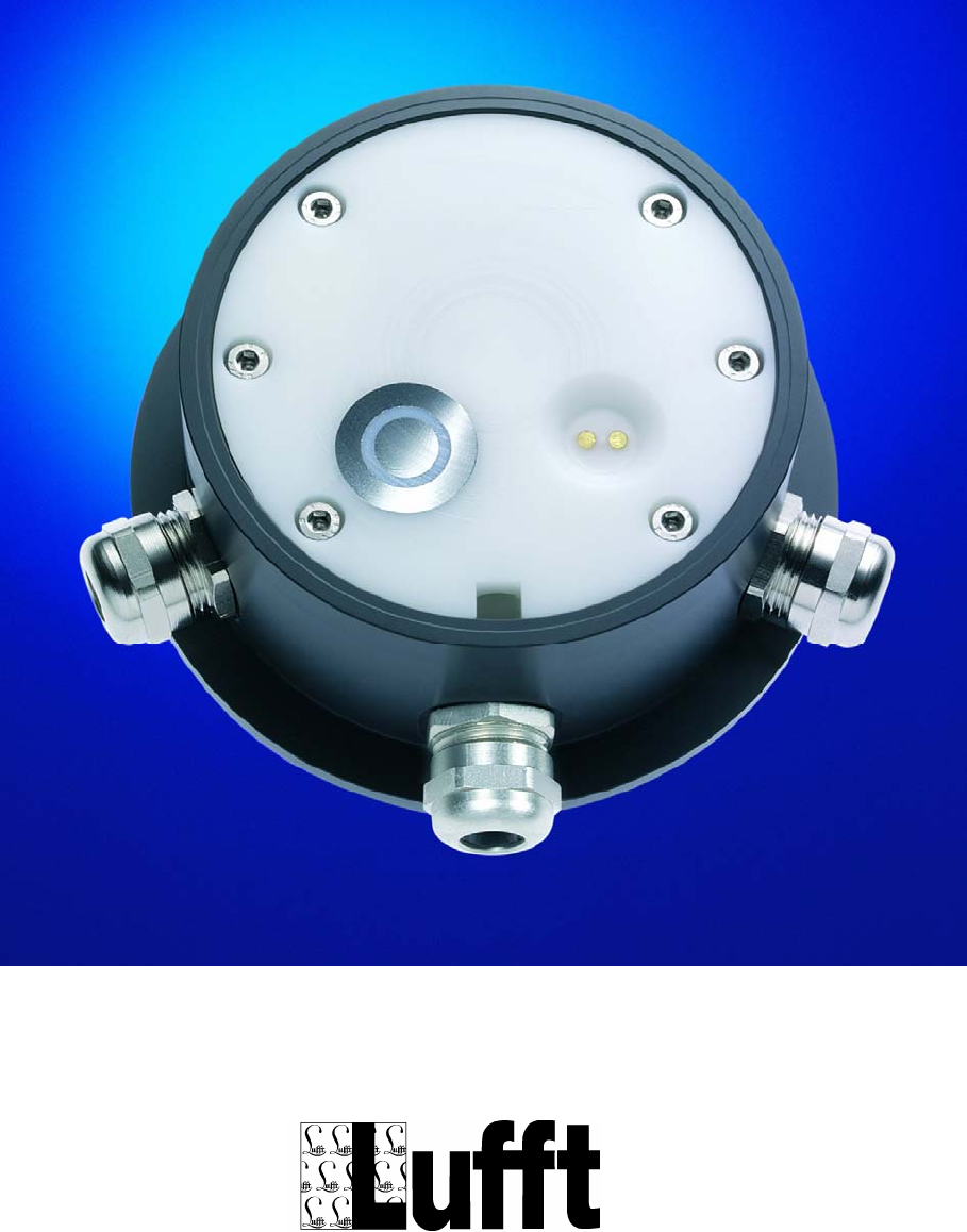
Manual IRS21
Version V1.29C (09/2006)

Technical Documentation IRS20/21
Page 2 of 37
Table of contents
1 GENERAL REMARKS 4
2 STORAGE CONDITIONS 5
3 OPERATING CONDITIONS 5
4 APPROVALS 5
5 QUALITY 5
6 SYSTEM DESCRIPTION 6
6.1 HARDWARE 6
6.2 THE INTERFACES 8
7 MOUNTING AND INSTALLATION 10
7.1 PREPARATION 10
7.2 MOUNTING 11
7.3 CONNECTION OF THE SUPPLY LEAD 12
7.4 COMMISSIONING AND TESTING 14
8 MAINTENANCE 14
8.1 EXCHANGE OF THE SENSOR 14

Technical Documentation IRS20/21
Page 3 of 37
9 IRS-21 PROTOCOL 16
9.1 INTRODUCTION 16
9.1.1 IRS-21 BUS PROTOCOLS 16
9.2 BINARY PROTOCOL 17
9.2.1 TELEGRAM SETUP (DESCENDING BYTE SERIES) 17
9.2.2 PHYSICAL CONDITIONS 17
9.2.3 COMMANDS 18
9.2.4 DEFINING THE IDENTIFICATION 22
9.3 ASCII-PROTOKOLL (IRS-21 <-> HOST COMPUTER) 23
9.3.1 PHYSICAL CONDITIONS AND FEATURES 23
9.3.2 COMMANDS FOR READING OUT MEASUREMENT VALUES 24
9.3.3 EEPROM CONFIGURATION + ADDRESSING THE RS485 BUS 27
9.4 BINARY PROTOCOL (IRS-21 OVER OPUS200/300 <-> HOST COMPUTER) 28
9.4.1 PHYSICAL CONNECTION AND HARDWARE STRUCTURE 28
9.4.2 SOFTWARE PROTOCOL 28
9.4.3 TELEGRAM AND DATA FORMAT 29
9.4.4 CONFIGURATION OF THE OPUS200 MODULES 32
9.4.5 CONFIGURATION OF THE ROAD SENSOR 33
ENCLOSURE 35
10 COMPLIANCE STATEMENT 36

Technical Documentation IRS20/21
Page 4 of 37
1 General remarks
The IRS-20/21 Road Sensor serves to monitor road conditions.
In contrast to most other sensors on the market, the IRS determines the road condition
within the sensor itself. This was made possible by means of a high-end microcontroller and
a sensor system which consists of the following components:
• Surface temperature measurement.
Two additional temperature sensors can be connected for measuring temperature under
ground. These latter values are not taken into account for determining the road condition.
• Multi-frequency measurement
• Measurement of salt concentration and freezing temperature
• Determination of the water film height on the surface of the sensor.
Depending on the measured values the IRS-20/21-software calculates a possible road con-
dition based on correlation factors and operates within a temperature range from –20°C to
+60°C.
For temperature values higher than a nominated temperature TPOS (default value 2ºC) the
model recognises the conditions "Dry", "Residual Salt", "Damp" and "Wet". Values below
TPOS additionally allow the determination of "Freezing Wetness", "Hoar Frost / Dry Snow"
and "Ice / Wet Snow".
The IRS-20 can be used only in combination with a Lufft datalogger OPUS 2.
The IRS-21 can be connected to any host computer which is able to support one of the
communication protocols described in chapter 9.
Furthermore, the sensor has the following characteristics:
• Compact construction and easy installation
• Low maintenance
• Resistant to physical and chemical influences
• Exchangeable even when installed
• Data transmission via RS 485 (IRS-21)
• Measurement time < 2s, therefore low energy consumption

Technical Documentation IRS20/21
Page 5 of 37
2 Storage conditions
Permissible ambient temperature ...............................-30°C ... +70°C
Permissible relative humidity ......................................0...100 % rel. humidity
3 Operating Conditions
Permissible ambient temperature ..............................-30°C ... +70°C
Permissible relative humidity .....................................0...100 % rel. humidity
Protection Class..........................................................IP68
4 Approvals
Design conforms to CE
5 Quality
Warranty period ..........................................................2 years
Maintenance interval...................................................annually

Technical Documentation IRS20/21
Page 6 of 37
6 System description
6.1 Hardware
The sensor consists basically of two components:
• Basic housing with connection cables for communication and power supply
• Housing cover with sensor electronics and evaluation electronics
These two components are joined together by 6 screws.
Two concentric circles on the sensor surface provide the measurement values for the multi-
frequency measurement. Alonside, in a recess, there are two electrodes that provide infor-
mation about salt concentration and thereby the freezing temperature. Additionally, a tem-
perature sensor, which determines the surface temperature, is installed in the central elec-
trode.
Beneath the remainder of the surface is the aerial for the impedance sensor, by means of
which the water film height above the cover can be determinded.
The printed circuit board, which contains the signal conditioning and evaluation electronics,
is also directly connected to the cover. Data is output via an RS485 interface.
Important!!
Power consumption during measurement is approximately 200 mA. In order to exclude
measurement errors through self-heating, the IRS-20/21 should only be supplied with power
only for approx. 2s.
For the IRS-20 this is controlled by the OPUS2.
The IRS-21 must be switched on and off by the control program of the host system.
After data interrogation, therefore, the sensor must be free of voltage. The measurement
interval must be >1 minute.
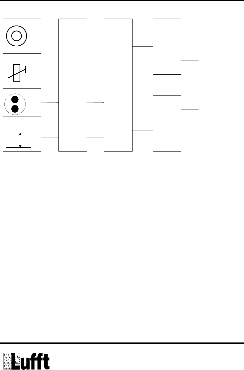
Technical Documentation IRS20/21
Page 7 of 37
h
Multi-frequency
Temperature
Freezing temp.
Water film
Signal conditioning
Controller
RS485
Power supply
A
B
12V
GND
Illustration 1: IRS-20/21 Schematic Unit Diagram
Technical Documentation IRS20/21
Page 8 of 37
6.2 The Interfaces
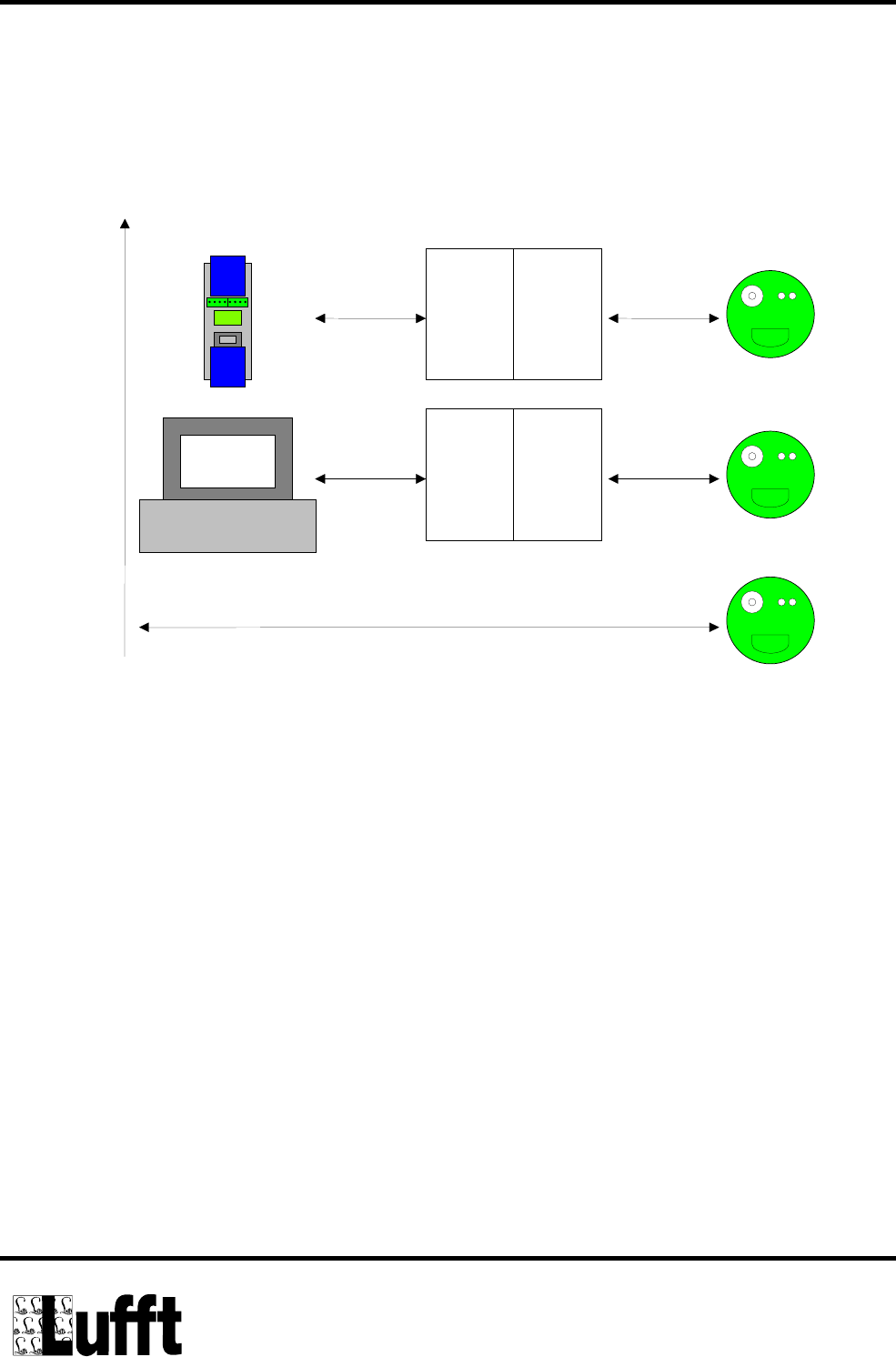
Illustration 2 shows three possible combinations by means of which the IRS-20/21 can
communicate with terminal devices. Please also consider the manual 8410.KON2.
8161.SV3
Mains
Unit Level
Transducer
8160.RS485
8161.SV3
Mains
Unit Level
Transducer
8160.RS485
Null-Modem Cable
RS232 Interface
IRS Configurations
Via OPUS200
Open Protocol
OEM Applications
Via RS232-PC
Open Protocol
OEM Applications
Via RS485
Open Protocol
OEM Applications
RS485/ UB=12V, clocked (both electrically isolated for all sensors)
Radar
IRS-20
Radar
Radar
Illustration 2: IRS-20/21 Connection Possibilities
The combination IRS-20 and OPUS200 is useful when, in addition to the IRS-20 data, addi-
tional measurement values are to be distributed via a common interface. Interrogation takes
place via the RS232 interface of the OPUS200/300.
The combination IRS-20 and PC (RS232 terminal device) can be applied when the terminal
device has an RS232 interface. The modem control lines can be used in combinations with
an appropriate program for switching the data direction (from the host computer to the IRS-
21 and/or from IRS-21 to the host computer) as well as the power supply of the IRS-21.
Concerning the hardware, this function is provided by the combination mains unit
(8161.SV3) and level transducer (8410.KON2). The terminal device software is responsible
that power is not supplied longer than it is necessary for the data transmission. The meas-
urement interval must be >=1 minute.

Technical Documentation IRS20/21
Page 9 of 37
The same conditions apply when the sensor is read out directly via the RS485 interface.
When using the level transducer (8410.KON2) the following aspects must be taken into ac-
count in the control software of the host computer (PC):
• The modem control line 'DTR' (Pin 4 of a 9 pin RS232 cable) switches the IRS power
supply 'on' (H level [approx. +10 V]) or 'off' (L level [approx. -10 V]), respectively. The
current state can be seen on a red LED on the circuit board of the level transducer.
• The modem control line 'RTS' (Pin 7 of a 9 pin RS232 cable) controls the data direction
(halfduplex) from the host computer to the IRS (L level [approx. -10V]) or from the IRS to
the host computer (H level [approx. +10V]), respectively.
• The IRS is always the slave. That means, the communication is always initiated by the
host program.
• Before starting the communication, the IRS power supply has to be switched on for
about 2 seconds, so that the sensor can carry out measurements. Commands which the
host system sends too early will be ignored by the IRS.
• Immediately after transmitting the command telegram, the host computer must switch
the data direction of the level transducer to 'IRS to host' by using the 'RTS' control line.
• The level transducer will instantaneously return all characters sent by the host (echo).
These should be ignored by the control software.
• The IRS will wait about 100ms before answering.
• After reception of the IRS answer the data direction should be switched back to 'host to
IRS' and the power supply for the road sensor should be deactivated.
The protocols for data transmission can be found from chapter 9 onward.

Technical Documentation IRS20/21
Page 10 of 37
7 Mounting and Installation
The road sensor is installed in the centre of the road lane. On two lane carriageways instal-
lation takes place in the left-hand lane.
7.1 Preparation
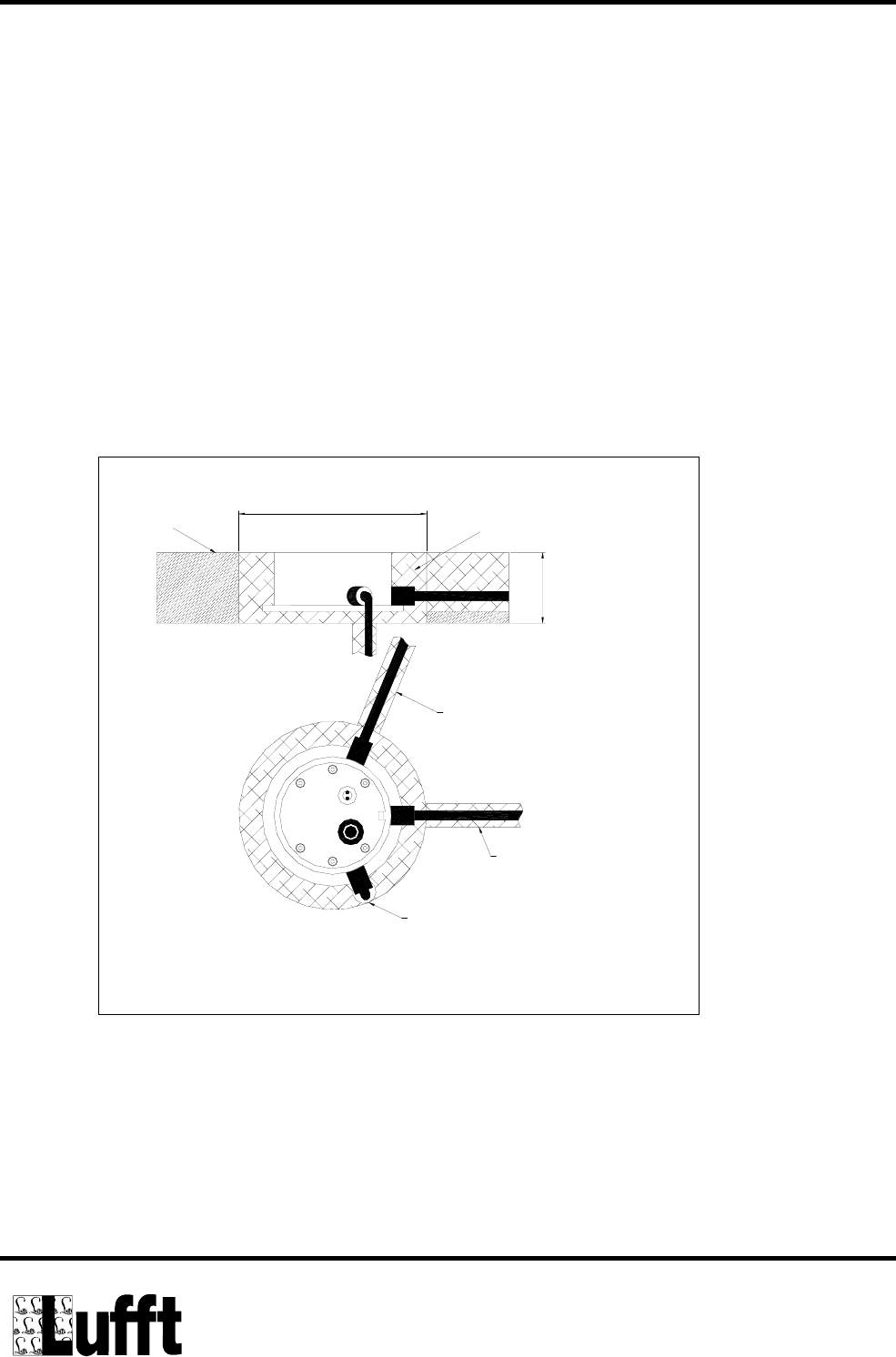
For inserting the sensor you need a drill hole with a diameter of 16 cm and a depth of 6 cm.
For the connection cable mill-cut a slot of width 2cm and depth 5cm into the road surface.
Attention! Be careful not to damage the isolation layer when working on bridges. A
depth of 6cm may not be possible in any case.
The installation of temperature sensor 1 (optional) requires an additional slot in an angle of
about 68º from the connection cable slot. The temperature sensor slot will be mill-cut into
the road with a width of 2 cm, depth 5 cm and length 35 cm.
For temperature sensor 2 (optional) a drill hole of 30cm depth with diameter 2cm is re-
quired. This is supposed to be positioned in an angle of about –68º on the outer rim of the
road sensor bore hole.
The external temperature sensors are protected to IP67. Constant use under water has to
be avoided.

Technical Documentation IRS20/21
Page 11 of 37
7.2 Mounting
Warning: The cable unions must no be opened in any case!
Shortening the cable is only permitted at the cabinet end of the cable. The cable must be
placed in a protection tube which prevents pavement expansions from being transmitted to
the cable. Be careful not to expose the sensor cables to tensile stress during the installation!
Warning: Damages on the cable sheathing or on the external temperature sensors
will lead to water entering the sensor! Sensors with damaged cabled must not be
built in and can only repaired by Lufft.
The road sensor is inserted into the corresponding drill hole so that its surface flushes with
the pavement. In order to achieve this, put the mounting bracket which is fixed on the sen-
sor on the rim of the drilling hole. If necessary, adjust the sensor position by bending the
mounting bracket.
Important:
The road sensor must by no means jut out over the pavement surface (Possible dam-
ages through snow clearing vehicles!).
Hollow spaces will be filled with resine concrete.
Important: Reaction heat in the resine concrete curing process can sometimes reach
temperatures over 80 °C (176ºF) which will damage the road sensor. It is important to
use only materials whose temperature remains below 80 °C (176ºF) in the curing
process!
When the filling compound is hardened, remove the mounting bracket and the green plastic
protection layer. The screws of the mounting bracket must be re-inserted in the correspond-
ing screw holes of the road sensor (turning moment 2 Nm).
Technical Documentation IRS20/21
Page 12 of 37
7.3 Connection of the Supply Lead
The road sensor supply lead is connected with the power supply and the bus system of the
evaluation electronics in the control panel.
Connection of the road sensor supply lead:
brown positive power supply
white negative power supply
yellow RS485_A
green RS485_B
Attention: Errors in connection will destroy the road sensor!
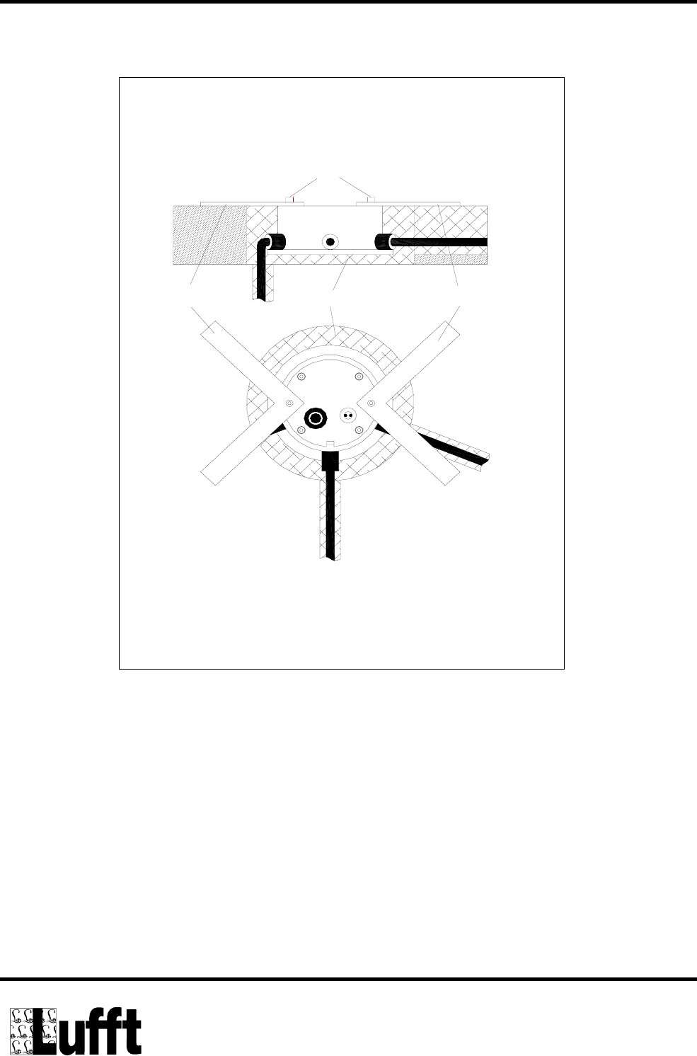
Illustration. 3: IRS20/21 Installation in the road
road sensor
min. Ø 16 cm
6 cm
resine concrete
road surface
road sensor
drill hole: Ø 2 cm
deep: 30 cm
slot 2 cm wide
5 cm deep
35 cm long
slot 2 cm wide
5 cm deep
Technical Documentation IRS20/21
Page 13 of 37
hexagon socket
installation aid installation aid
resine concrete
Illustration 4: Mounting the IRS20/21

Technical Documentation IRS20/21
Page 14 of 37
7.4 Commissioning and Testing
After successful installation of the road sensor, its correct functioning should be checked.
Connect the sensor to your evaluation device and check whether the communication be-
tween the sensor and the evaluation unit works properly. The road condition which is de-
termined by the sensor should be checked for dry and wet sensor.
8 Maintenance
The road sensor should be serviced annually. This includes the visual inspection of the
housing. It is recommended to clean the sensor surface when very dirty. Where there is sig-
nificant mechanical damage to the sensor, which could influence the tightness of the hous-
ing, it is recommended to exchange the sensor. This also applies in the case where the
plastic assembly of the sensor is heavily degraded by wear and tear.
8.1 Exchange of the sensor
If the plastic assembly of the road sensor becomes unusable due to mechanical effects, or
the sensor electronics are damaged, the plastic assembly can be exchanged without the
need to exchange the entire housing.
Attention:
Exchange must only be carried out when the road is dry!
To uninstall the plastic assembly remove all six hexagonal screws. On the edge of the cover
there is a small opening that serves to provide access for a screwdriver. Thereby the plastic
assembly can be lifted out. Take care not to pull out the connection cables on the underside
of the sensor. The plug connections must be removed without tensile strain on the cables!

Technical Documentation IRS20/21
Page 15 of 37
Important:
when changing the sensor the ring gasket must always be replaced and a new drying
agent bag must be laid in!
The housing has to be cleansed carefully before inserting a new sensor. Even tiny dirt parti-
cles in the gasket fit may lead to sensor failure in the long term! No humidity must be en-
closed in the housing! The new drying agent bag must be taken out of the sealed protection
cover only shortly before being placed in the housing. The sticker on its outside indicates
the functioning (blue: ok, pink: the drying agent is spent).
When connecting the new sensor to the plugs be careful not to touch the electronics of the
sensor. Electrostatic discharge may easily destroy the sensor!
The gasket has to be placed using silicone grease. It must not cant when the plastic cover
plate is inserted. The plastic cover plate must fit into the housing without the use of force.
Grease the thread of the fixing screws. First lightly fasten the screws and then tighten them
one by one proceeding in pairs of screws placed opposite each other.

Technical Documentation IRS20/21
Page 16 of 37
9 IRS-21 Protocol
9.1 Introduction
Both types of intelligent road sensors are equipped with 2 different types of interfaces for
the communication with superordinate systems:
• IRS-20: Only for use with the Lufft datalogger OPUS-2.
(The protocol of this interface is not included in this manual)
• IRS-21: Flexible connection of several road sensors via one RS485 interface
(2 wire, half duplex) to a customer designed host computer
9.1.1 IRS-21 bus protocols
The IRS-21 provides for 2 different communication protocols in order to grant easy connec-
tivity to a superordinate host system:
• Binary protocol (Chapter 10.2)
Data frame limited by the control characters STX (02h) and ETX (03h)
CRC (cyclic redundancy check)
• ASCII protocol (Chapter 10.3)
Plain text protocol with end characters CR (0Dh) + LF (0Ah)
Both types can be used on a bus, i.e. every road sensor can have its own address and be
connected to a host computer.

Technical Documentation IRS20/21
Page 17 of 37
9.2 Binary protocol
The binary protocol is used for connecting host computer (e.g. OPUS200) to the Intelligent
Road Sensor via RS485:
9.2.1 Telegram setup (descending byte series)
Byte number Meaning Abbr Range
1 Telegram start STX 0x02
2 Identicifacation ID 0 ... 250
3 Length CNT 1 ... 255
4 Command CMD 0 ... 255
5 ... n Additional data D0 ... Dn 0 ... 254 Bytes
n + 1
n + 2 Block check CRC_L
CRC_H
16 Bit CRC check sum
from ID until the last Data byte
n + 3 End of telegram ETX 0x03
9.2.2 Physical conditions
Interface: RS485 – 2 wire (half duplex)
Data bits: 8
Stop bits: 1
Parity: none
Baudrate: 19200 Baud (Default setting)
(1200 Bd., 2400 Bd., 4800 Bd., 9600 Bd., 19200 Bd., 38400 Bd. can be
adjusted)
Check sum: 16 Bit CRC from Ident.-Byte (ID) until the last data byte
CRC polynomial: x16 + x12 + x5 + 1 (LSB first mode); see enclosure
Timeout: Answer from the slave must be available max. 0.5 Sec. after request from the
master
Ident: On delivery = 0

Technical Documentation IRS20/21
Page 18 of 37
9.2.3 Commands
9.2.3.1 Request of data from IRS21 to host
Sensor is connected (CMD = 0x00)
Host: STX, ID, CNT = 2, CMD = 0x00, D0, CRC_L, CRC_H, ETX
IRS-21: STX, ID, CNT = 2, CMD = 0x00, inverted D0 value, CRC_L, CRC_H, ETX
Example: Master sends D0 = 0x55, IRS-21 answers D0 = 0xAA
Request of soft and hardware version (CMD = 0x01)
Host: STX, ID, CNT = 1, CMD = 0x01, CRC_L = 0x51, CRC_H = 0x08, ETX
IRS-21: STX, ID, CNT = 3, CMD = 0x01, D0 = HW, D1 = SW , CRC_L, CRC_H, ETX
Example: HW = 04 -> hardware version 0.4; SW = 23 -> software version 2.3
Request of individual sensor data (CMD = 0x02)
Host: STX, ID, CNT = 2, CMD = 0x02, D0 = Sensor (see table), CRC_L, CRC_H, ETX
IRS-21: STX, ID, CNT = 3, CMD = 0x02, D0 = Lowbyte (see table), D1 = Highbyte
(see table below), CRC_L, CRC_H, ETX
Host
D0 = Sen-
sor
Sensor type Range IRS-21
D0 = Low- / D1 = Highbyte
0 Internal temperature
sensor
0 ... 2000 Digits =
-50,0 °C ... +150,0 °C.
0 ... 2000
in case of error 50000
1 External temperature
sensor - 1
0 ... 2000 Digits =
-50,0 °C ... +150,0 °C.
0 ... 2000
in case of error 50000
2 External temperature
sensor - 2
0 ... 2000 Digits =
-50,0 °C ... +150,0 °C.
0 ... 2000
in case of error 50000
3 Multi frequency – 1000k 0 ... 255 Digits 0 ... 255 / 0

Technical Documentation IRS20/21
Page 19 of 37
4 Multi frequency – 500k 0 ... 255 Digits 0 ... 255 / 0
5 Multi frequency – 200k 0 ... 255 Digits 0 ... 255 / 0
6 Multi frequency – 51k 0 ... 255 Digits 0 ... 255 / 0
7 Salt concentration
Freezing temperature
0 ... 250 Digits =
0,0 % ... 25, 0% (NaCl)
0 ... 250 Digits =
0,0 °C ... -25.0 °C.
Lowbyte: 0 ... 255
Highbyte: 0 ... 255
8 Impedance sensor 0 ... 250 Digits =
Normalised value
0...255 Digits =
Humidity adaptation
Lowbyte: 0 ... 250
Highbyte: 0 ... 255
9 Water film height 0 ... 4000 Digits =
0 ... 4000 μm
0 ... 4000
Request of sensor data for being stored in the host as a block (CMD = 0x03) (CMD =
0x03)
Host: STX, ID, CNT = 1, CMD = 0x03, CRC_L = 0x43, CRC_H = 0x2B, ETX
IRS-21: STX, ID, CNT = x, CMD = 0x03, D0 ... D13 (see table below), CRC_L, CRC_H,
ETX
IRS-21 D0 ... D11 Meaning
0 / 1 Internal temp. sensor (0 ... 2000 Digits = -50,0 °C ... +150,0 °C.)
(Byte 0 = Lowbyte, Byte 1 = Highbyte)
2 / 3 Externeral temp. sensor - 1 (0 ... 2000 Digits = -50,0 °C ... +150,0 °C.)
(Byte 2 = Lowbyte, Byte 3 = Highbyte)

Technical Documentation IRS20/21
Page 20 of 37
4 / 5 External temperature sensor – 2 (0 ... 2000 Digits)
(Byte 4 = Lowbyte, Byte 5 = Highbyte)
6 / 7 Byte 6 = Freezing temperatures (0 ... 250 Digits)
Byte 7 = 0
8 / 9 Byte 8 = Normalised radar value (0 ... 250 Digits)
Byte 9 = 0
10 / 11 Water film height (0 … 4000 Digits = 0 ... 4000 µm)
(Byte 10 = Lowbyte, Byte 11 = Highbyte)
12 / 13 Byte 12 = Defined Road Condition (0 ... 99)
0: Dry
1: Damp
2: Wet 3: Ice
4: Frost/Snow 5: Residual salt
6: Freezing wet > 6: Undefined condition
Byte 13 = Physical Road Conditions (0 ... 99)
0: Dry 1: Residual salt
2: Damp 3: Wet
4: Freezing wet 5: Hoarfrost
6: Dry snow 7: Dry ice
8: Wet snow 9: Ice
> 9: Undefined condition
The defined road condition is a subset of the physical road condition.

Technical Documentation IRS20/21
Page 21 of 37
Read out individual EEPROM memory cells (CMD = 0x04)
Host: STX, ID, CNT = 3, CMD = 0x04, D0 = Lowbyte address, D1 = Highbyte
address, CRC_L, CRC_H, ETX
IRS-21: STX, ID, CNT = 5, CMD = 0x04, D0 = Lowbyte address, D1 = Highbyte adres-
se
, D2 = Lowbyte date, D3 = Highbyte date, CRC_L, CRC_H, ETX
Note: The EEPROM address range is 0 ... 2047.
Read out EEPROM memory cells as block (CMD = 0x05)
Host: STX, ID, CNT = 4, CMD = 0x05, D0 = Lowbyte start address, D1 = Highbyte
Start address, number of words, CRC_L, CRC_H, ETX
IRS-21: STX, ID, CNT = 3 + 2 x number of words, CMD = 0x05, D0 = Lowbyte start ad-
dress,
D1 = Highbyte start address, D2 = Lowbyte date, D3 = Highbyte date,
D4 = Lowbyte date, ..., Dn = Highbyte date, CRC_L, CRC_H, ETX
Note: The number of words is limited to 32 (= 64 Byte).
9.2.3.2 Transmission of data from host to IRS-21
Write individual EEPROM memory cells (CMD = 0x10)
Host: STX, ID, CNT = 5, CMD = 0x10, D0 = Lowbyte address, D1 = Highbyte adress,
D2 = Lowbyte date, D3 = Highbyte date, CRC_L, CRC_H, ETX
IRS-21: STX, ID, CNT = 1, ACK = 0x06 = OK or NACK = 0x15 = error, CRC_L,
CRC_H, ETX
Disable ASCII protocol (CMD = 0x11)
Host: STX, ID, CNT = 1, CMD = 0x11, CRC_L = 0xD0, CRC_H = 0x18, ETX
IRS21: STX, ID, CNT = 1, ACK = 0x06 = OK, CRC_L, CRC_H, ETX
Enable ASCII protocol (CMD = 0x12)
Host: STX, ID, CNT = 1, CMD = 0x12, CRC_L = 0x4B, CRC_H = 0x2A, ETX
IRS21: STX, ID, CNT = 1, ACK = 0x06 = OK, CRC_L, CRC_H, ETX

Technical Documentation IRS20/21
Page 22 of 37
RESET - IRS-21 (CMD = 0x1F)
Host: STX, ID, CNT = 1, CMD = 0x1F, CRC_L = 0xAE, CRC_H = 0xF1, ETX
IRS-21: STX, ID, CNT = 1, ACK = 0x06 = OK, CRC_L, CRC_H, ETX
Note: After transmitting 'OK' the sensor is re-set.
9.2.3.3 IRS-21 answer in case of receiving wrong data from the host
IRS-21: STX, ID, CNT = 1, NACK = 0x15 = Not Acknowledged (Data were not accepted),
CRC_L, CRC_H, ETX
9.2.4 Defining the identification
2 scenarios are possible:
• Establishing a new bus line
• Connecting an additional sensor to an existing bus line
The default identification [short ID] (=0) should have been changed previously. By using
ID=0 all sensors in a bus line are contacted.
Important!
It is important to make sure that the new sensor has a different ID from the sensors which
are already in the line. As discussed above the new ID should be >0. The possible range is
0…250.
The command for transferring the new identification is basically the same as the one for
writing EEPROM cells:
Host: STX, ID, CNT = 5, CMD = 0x10, D0 = 0x05, D1 = 0x00, D2 = new ID, D3 = 0x00,
CRC_L, CRC_H, ETX
IRS-21: STX, ID, CNT = 1, ACK = 0x06 = OK or NACK = 0x15 = error, CRC_L,
CRC_H, ETX
In order to have the sensor accept the new ID it has to be re-started with the reset com-
mand (with the old identification still) or by switching it off and on again.

Technical Documentation IRS20/21
Page 23 of 37
9.3 ASCII-Protokoll (IRS-21 <-> host computer)
In addition to the above binary protocol measured values can be requested in plain text from
the IRS-21. To this end, a terminal software is needed which converts incoming and outgo-
ing data from COM ports to RS485 – 2 wire bus (halfduplex).
9.3.1 Physical conditions and features
Parameter Options on request Default settings
Baudrate 2400 - 38400 Baud 19200 Baud
Data bits 8 (fix) 8
Stop bits 1 (fix) 1
Interface settings for the ASCII protocol
The following features have to be taken into account:
• Any command of the Host must be preceeded by '&' or '$'
• Any telegram from the host to the IRS-21 is ended by ‘CR’ (= 0Dh). All further characters
will be ignored.
• Answers from the IRS to the host are always ended by ‘CR & LF’ (= 0Dh & 0Ah).
• If several values IRS->Host are trasmitted (e.g. the values of 3 temperature sensors),
these will be seperated from one another by 1 'Space' (=20h). Groups of measuring val-
ues (e.g. water film and road condition) are separated from one another by 3 'Spaces'.
• In case of errors (e.g. wrong E2 memory cell) the IRS sends ‚NACK’ + ‚CR’ + ‚LF’
• For data handover the indicated digits may be reduced
(e.g. read address 24 of the EEPROM: command EL0024 + ‚CR’ or EL24 + ‚CR’).

Technical Documentation IRS20/21
Page 24 of 37
9.3.2 Commands for reading out measurement values
Com-
mand Function
&T
+’CR’
Output of the normalised values of 3 temperature sensors:
1st Value = External Sensor-1
2nd Value = External Sensor-2
3rd Value = Internal Sensor
The respective value range covers 0 ... 2000 Digits = -50,0 ° ... +150,0 °C.
For a non-connected or defective sensor the value is always 'xxx'.
&F
+’CR’
Output of the normalised values of 4 frequencies of the multi-frequency measure-
ment:
1st Value = F1000k range
2nd Value = F500k range
3rd Value = F200k range
4th Value = F51k range
The respective value range covers 0...255 digits.
In case of a dry or wet but clean road, the values tends towards 255. On the other
hand, this value comes near '000' when the road is wet and dirty.
For non-tuned or faulty frequency measurement the values are always set at 'xxx'.
&L
+’CR’
Output of the normalised conductivity measurement values
1st Value = Concentration of the salt solution 0 ... 250 Digits = 0,0 % ... 25, 0%
(NaCl)
2nd Value = Freezing temperature of the salt solution 0...50 Digits = 0,0 ... -25.0°C.
In case the measurement cannot be determined, both values are set to 'xxx'. The
measuring range for determining the salt concentrations is –20 °C... + 15 °C (inter-
nal temperature sensor).
&R
+’CR’
Output of the normalised water film height in 0 ... 250 digits.
On a dry road the water film value tends towards 150 (=dry). With increasing water
level the value declines towards '000'.
For non-tuned water film measurement the value is always set to 'xxx'.The water
film can be measured up to +60°C air temperature.

Technical Documentation IRS20/21
Page 25 of 37
&Z
+’CR’
Output of the road conditions in figures 0...99:
0 = Dry
1 = Damp
2 = Wet
3 = Icy
4 = Frost / Snow
5 = Residual Salt
6 = Freezing Wet
98, 99 = undefined values (road conditions could not be determined).
Road condition 99 is displayed when measuring below –20 °C and above +60 °C.
&A
+’CR’
Output of all the above values in order T, L, R, Z.
There are always 3 'spaces' (=20h) between the different measurement groups (e.g.
'T' and 'F').
Furthermore, the error state of the sensor is transmitted at the end of the line.
The following error conditions have been defined:
‘000’ = The unit is in order.
‘001’ = The external temperature sensors are not connected or faulty
> ‘001’ = The unit is faulty
&V
+’CR’
Output of the hard and software version.
e.g. 0.4 (= HW Version) 2.0 (= SW Version) 16.06.00 (SW creation date)
Technical Documentation IRS20/21
Page 26 of 37
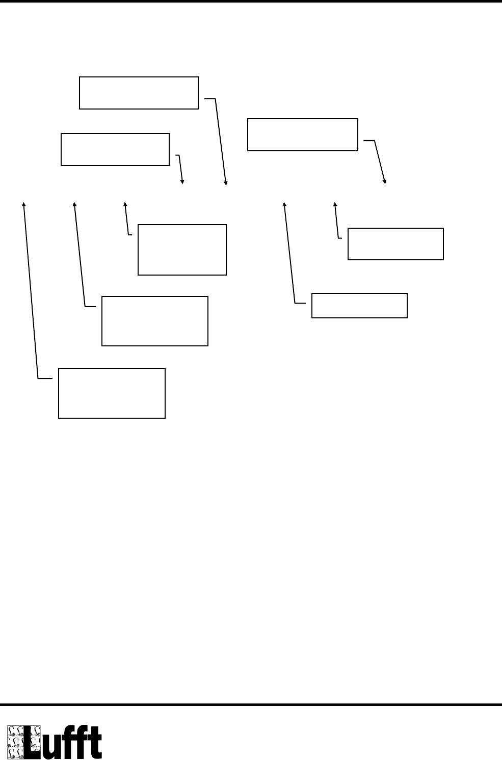
Example of data output after the command &A↵ has been sent by the host computer
(standard output)
0423 0424 0423 020 010 144 01 000
External
temp. sensor -1
= - 7,7 °C
External
temp. sensor -2
= - 7,6 °C
Internal
temp. sensor
= - 7,7 °C
Salt concentration
= 2,0 % NaCl
Freezing tempera-
ture
water film height
Road condition
= damp
Error status
= unit in order

Technical Documentation IRS20/21
Page 27 of 37
9.3.3 EEPROM configuration + addressing the RS485 Bus
Command +
Data Function
&ELxxxx + ’CR’ Read EEPROM memory cell with address xxxx
Address = 0 ... 2047, displayed value = 0 ... 65535 (2 Byte)
Answer: yyyyy (= E2 contents) + ‚CR’ + ‚LF’
&Essxxxx yyyyy
+ ’CR’
Write EEPROM on address xxxx with value yyyyy
Address=0 ... 2047, Value=0 ... 65535
Answer: yyyyy (= E2 contents written and re-read) + ‚CR’ + ‚LF’.
$ + ’CR’ Read RS485 bus ident (address) and bus selector
Answer: xxx (= Ident) + 3 Spaces + yyy (= Selector) + ‚CR’ + ‚LF’.
$Ixxx + ’CR’ Assign RS485 bus ident (address) and configuration of the bus selec-
tor to this address.
Ident-No.= 1 ... 255
Answer: xxx (= Ident) + 3 Spaces + yyy (= Selektor) + ‚CR’ + ‚LF’.
$Sxxx + ’CR’ Set new RS485 bus selector (=selection of an IRS)
Selektor No = 0 ... 255
Answer: xxx (= Ident) + 3 Spaces + yyy (= Selektor) + ‚CR’ + ‚LF’.
Addressing the IRS bus is possible only from sw version 2.2 onwards.
Remarks about the RS485 bus ident and selector:
The bus ident corresponds to the bus address in the binary protocol.
The bus selector is used for selecting a determined IRS. All other participants on the bus
will remain passive until a new selector no. is set. A new ident no. can only be assigned to a
selected IRS.
The selector no. is set to the new value at the same time as the new ident no. The IRS re-
mains therefore selected in spite of the changed ID. Every participant in the bus must have
its own ident no.

Technical Documentation IRS20/21
Page 28 of 37
9.4 Binary protocol (IRS-21 over OPUS200/300 <-> host computer)
9.4.1 Physical connection and hardware structure
The sensors are connected to the host system via OPUS200 modules. Each of these mod-
ules can bear 1 road senor or 2 standard sensors (temperature / humidity etc.) and they are
connected among each other by CAN bus. Further modules can be added if necessary.
Each of these modules can be used as interface to the host system with the exception of
the ones which are connected to an intelligent road sensor. The connection is established
through the RS232 interface. The baudrate is 19200 with 8 data bits, no parity and 1 stop bit
(8N1). All sensors connected to the system can be addressed and read out via the RS232
connection.
9.4.2 Software protocol
The sensors are adressed and read out with a defined protocol through the host computer.
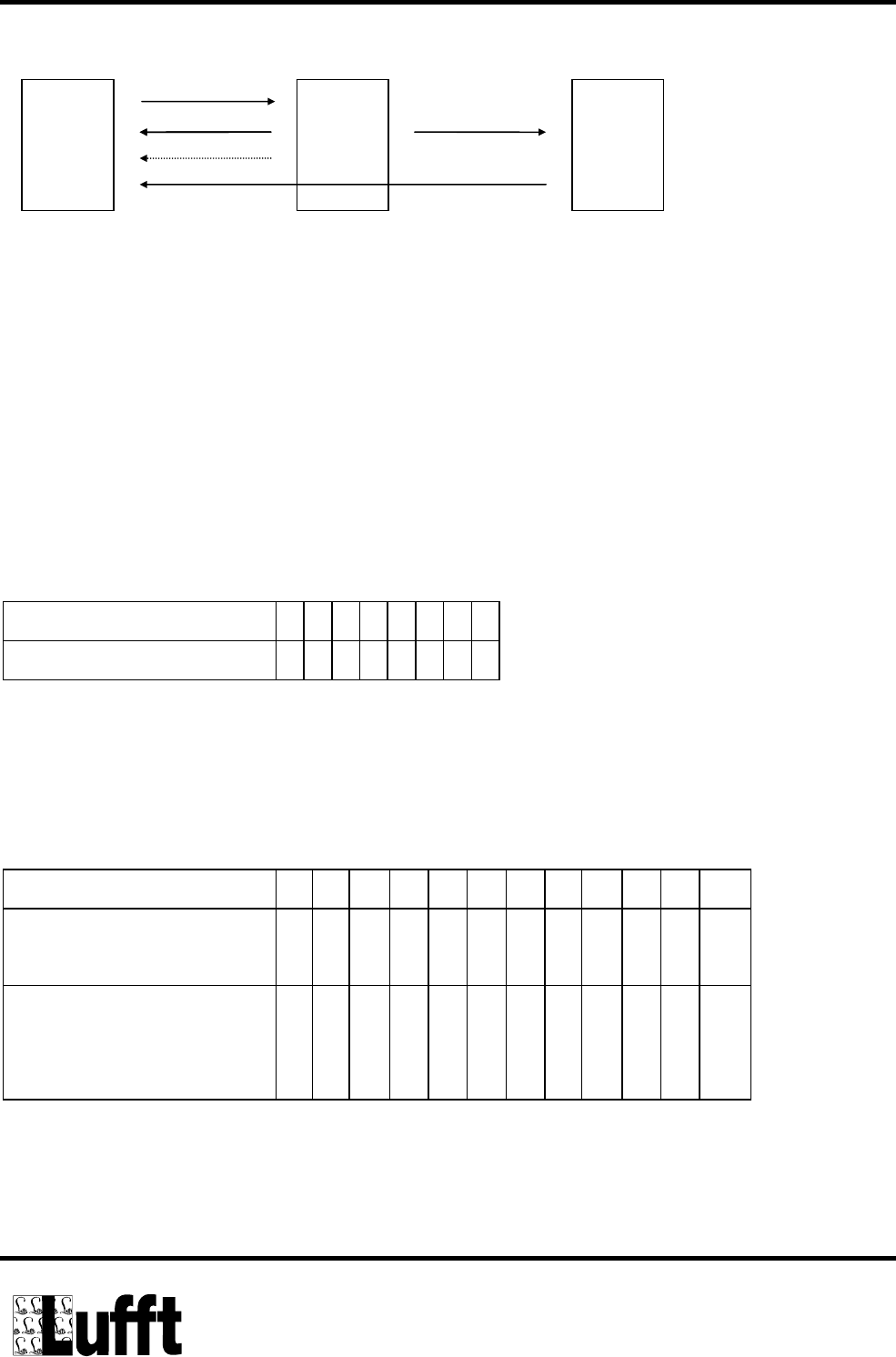
The host computer will send an inquiry telegram in cyclical intervals to each OPUS200 in
the system. If the OPUS which is connected to the serial interface has received the tele-
gram correctly, it will send an ACK telegram. In case an error is detected, it will send a
NACK telegram. If the telegram has been received correctly, the OPUS200 to which the
inquiry was designated will answer by sending the current values to the host computer.
The polling has to be done synchronously. The sensors and transmitters will not initiate any
messages on their own. The floating measurement values are mapped linearly to a normal-
ised value range of 0 – 65520 (= standard transmission protocol), with 0 corresponding to
the mimimum and 65520 to the maximum measurement value of the installed sensor. The
values above 65520 are used as error codes.
Technical Documentation IRS20/21
Page 29 of 37
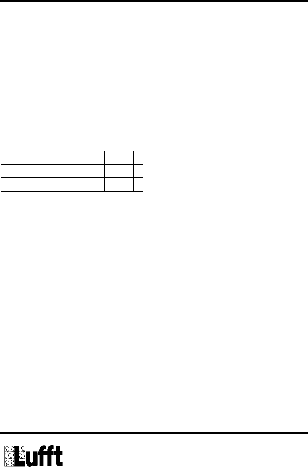
Host computer OPUS designated OPUS
9.4.3 Telegram and data format
9.4.3.1 Data format:
LONG: LowLowByte LowHighByte HighLowByte HighHighByte
INT: LowByte HighByte
9.4.3.2 Telegram format
Inquiry telegram
Byte 1 2 345678
Online data inquiry ? N xxxxcc
x : Address of the OPUS200 as LONG
cc: sum of all preceeding bytes as INT (LSB first)
Answering telegram
Byte 1 2 3 4 5 6 7 8 9 10 11 12
Online data answer at up
to 4 measured values,
? N v1 v1 v2 v2 v3 v3 v4 v4 c c
in case of more than 4
measured values, a sec-
ond telegram will follow
? N v5 v5 v6 v6 v7 v7 c c - -
v1 – v7: Maximum of 7 measurement values, each as INT.
The number of measurement values transmitted by an OPUS depends on the respective
configuration. If the OPUS provides only average values over the storage interval, only the
Inquiry
ACK
NACK
Answer
Technical Documentation IRS20/21
Page 30 of 37
measurement values v1 and v2 will be sent. If the minimum and/or maximum values of the
storage interval shall also be delivered, the number of values increases to 4 or 6, respec-
tively..
When an IRS-21 is connected to an OPUS (see Chapter 10.4.3.3), a maximum of 7 meas-
urement values can be transmitted.
cc: sum of all preceeding bytes as INT (LSB first)
ACK / NACK Telegram following an online inquiry
Byte 1 2 3 4 5
ACK Telegram $ ? N c c
NACK Telegram # ? N c c
cc: sum of all preceeding bytes as INT (LSB first)
9.4.3.3 Special case Intelligent Road Sensor (IRS-21)
An OPUS200 which has been configured for connecting an Intelligent Road Sensor uses
the same telegram format for transmitting data as do the OPUSses with standard sensors.
When the OPUS with the IRS receives an inquiry, it will send 2 telegrams with a total of 6 or
7 measurement values. In contrast to the standard OPUS 200, these measurement values
are not the average, maximum and minimum values, but have special meanings, which are
:
v1: internal temperature sensor IRS21 -50 °C – 150 °C
v2: external temperature sensor 1 IRS21 -50 °C – 150 °C
v3: external temperature sensor 2 IRS21 -50 °C – 150 °C
v4: Freezing temperature -25 °C – 0 °C

Technical Documentation IRS20/21
Page 31 of 37
At configuration for transmitting the normalized water film height:
v5: Normalized water film height 0 - 250
v6: Water film height 0 – 4000 µm
v7: Road condition 0 – 99
At configuration without transmitting the water film height:
v5: Water film height 0 - 4000 µm
v6: Road condition 0 – 99
All measurement values with the exception of the road condition are transferred in the stan-
dard transmission protocol (see Chapter 10.4.2) and have to be converted accordingly. The
road condition is transmitted directly (i.e. 0 – 99)
9.4.3.4 Error codes
The following error codes have been defined:
Designation Value
Value Over-
flow
0xFFF3 The measured value is above or below the sensor en-
trance range, or no is sensor connected
Conf Error 0xFFF4 An invalid configuration has been detected.
Xor Error 0xFFF5 The check sum over the E2 is wrong.
Invalid Value 0xFFFD

Technical Documentation IRS20/21
Page 32 of 37
9.4.4 Configuration of the OPUS200 modules
The configuration of an OPUS200 is carried out using the software SmartControl. Smart-
Control provides for the configuration of all sensors except the Intelligent Road Sensor. The
configurations of the OPUS200 has influences directly the size and the number of the an-
swering telegrams following an online inquiry (see telegram format of answering telegrams)

Technical Documentation IRS20/21
Page 33 of 37
9.4.5 Configuration of the Road Sensor
Any OPUS 200 which is supposed to communicate to a road sensor has to be configured
manually. This is carried out in the monitor mode by setting E2 address no. 368 to the value
of 98 (connect the OPUS200 to the serial interface, and switch it into the monitor mode with
!xxxxx (xx = id of the OPUS). The OPUS should send a small message to the terminal
program)
In the monitor mode use the command
ES 368 98
to write the value into the E2 address.
By setting E2 address no. 367 the output format can be defined. If this address carries the
value of 98, the normalized water film height will not be transferred and the codification of
the road condition is changed. (Command: ES 367 98)
After the following re-start "FASS" should be displayed on the OPUS.
An OPUS that is configurated for the road sensor has the following settings:
Measuring interval 60 seconds
Storage interval 10 minutes
Mode Sleep mode
The provided values (see telegram format: Special case Intelligent Road Sensor) have the
following meaning:
v1: internal temperature sensor Road surface temperature in the range -50°C - 150°C
v2: external temperature sensor 1 Temperature of the first external temperature sensor in
the range -50°C - 150°C
v3: external temperature sensor 2 Temperature of the second external temperature sen-
sor in the range -50°C - 150°C
v4: Freezing temperature Freezing temperature of the salt solution on the street
in the range -25°C - 0°C

Technical Documentation IRS20/21
Page 34 of 37
Configuration for transferring the normalized water film height (E2 address 367 - value un-
equal to 98)
v5: normalized water film height (Qualitative Water film height)
0 much water
150 no water
250 much ice
v6: Water film height Water film height between 0 and 4000 µm
v7: Road condition Road condition
0 dry
1 damp
2 wet
3 ice
4 frost / snow
5 residual salt
6 freezing wet
99 Road condition cannot be determined
Configuration without transferring the normalized water film height (E2 address 367 – value
equal to 98):
v5: Water film height Water film height between 0 and 4000 µm
v7: Road condition Road condition
1 dry
2 wet
3 ice
4 damp
5 residual salt
6 freezing wet
99 Road condition cannot be determined

Technical Documentation IRS20/21
Page 35 of 37
Enclosure
CRC-Calculation For IRS-20/21
The checksum is calculated according to the following rules:
Polynomial: 1021h = x16 + x12 + x5 + 1 (LSB-first-mode)
Start value: 0000h
(Note: Unlike the checksum calculation of the UMB-protocol the start value is not FFFFh but 0000h!
The UMB-protocol is used by devices clearly marked with the UMB logo.)
Please note that the checksum calculation starts with the second byte of the datagram.
Example
When calculating the checksum for several bytes the previously calculated checksum need
to be stored temporarily in an unsigned short variable. In the beginning, this variable has to
be initialized by 0000h.
/*************************************************************************
Function: 16 Bit CRC-Calculation For IRS-20/21
--------------------------------------------------------------------------
Parameter: calc_crc(unsigned short crc_buff, unsigned char input)
--------------------------------------------------------------------------
Return: CRC checksum
--------------------------------------------------------------------------
Diskription: Calculates CRC checksum using polynomial x^16 + x^12 + x^5 + 1
'crc_buff' holds the temporarily calculated checksum for 'input'.
'crc_buff' has to be initialized by 0x0000.
*************************************************************************/
unsigned short calc_crc(unsigned short crc_buff, unsigned char input)
{
unsigned char i;
unsigned short x16; // we will use this to hold the XOR mask
for (i=0; i<8; i++)
{
// XOR current D0 and next input bit to determine x16 value
if( (crc_buff & 0x0001) ^ (input & 0x01) )
x16 = 0x8408;
else
x16 = 0x0000;
// shift crc buffer
crc_buff = crc_buff >> 1;

Technical Documentation IRS20/21
Page 36 of 37
// XOR in the x16 value
crc_buff ^= x16;
// shift input for next iteration
input = input >> 1;
}
return(crc_buff);
}
// ******************* MAIN ************************************
void main(void)
{
// example: CRC for 8 Bytes
unsigned char values[8] =
{0x30, 0x31, 0x32, 0x33, 0x34, 0x35, 0x36, 0x37};
// initialise startvalue 0000h
unsigned short crc = 0x0000;
// calculation
for(int n = 0; n < 8; n++)
{
crc = calc_crc(crc, values[n]);
}
// output
printf("\ndata: 30h, 31h, 32h, 33h, 34h, 35h, 36h, 37h");
printf("\nCRC: %04Xh\n", crc);
}
Output:
data: 30h, 31h, 32h, 33h, 34h, 35h, 36h, 37h
CRC: 84CFh
10 Compliance Statement

Technical Documentation IRS20/21
Page 37 of 37
USA
This device complies with Part 15 of the FCC Rules. Operation is subject to the following
two conditions:
(1) This device may not cause harmful interference, and
(2) this device must accept any interference received, including
interference that may cause undesired operation.
Usually this is followed by the following FCC caution:
Any changes or modifications not expressly approved by the party responsible for compli-
ance could void the user's authority to operate this equipment.
Kanada
Operation is subject to the following two conditions:
(1) this device may not cause interference, and
(2) this device must accept any interference, including interference that may cause unde-
sired operation of the device."
Usually this is followed by the following RSS caution:
Any changes or modifications not expressly approved by the party responsible for compli-
ance could void the user's authority to operate this equipment.