G Way Solutions PS82070M Industrial Signal Boosters User Manual BDA PSX 20 20 70 M manual
G-Way Microwave / G-Wave Industrial Signal Boosters BDA PSX 20 20 70 M manual
UserManual.wiki
>
G Way Solutions
>
PS82070M User Manual
User Manual
Navigation menu
Upload a User Manual
Namespaces
Wiki Guide
HTML
PDF
Info
Views
User Manual
Discussion / Help
Navigation
![6 | P a ge Table1CODEUPLINKBAND DOWNLINKBANDBDA‐PS7W‐20/20‐70‐M(US)788‐805MHz758‐775MHzBDA‐PS7W‐20/20‐70‐MBDA‐PS7‐20/20‐70‐M(Canada)798‐806MHz768‐776MHzBDA‐PS8NEPS‐20/20‐70‐M(US)806‐816MHz851‐861MHzBDA‐PS8‐20/20‐70‐MBDA‐NPSPAC‐20/20‐70‐MBDA‐SMR‐0.15/0.15W‐35‐EBDA‐SMR‐0.5/0.5W‐70‐A(Canada)806‐824MHz851‐869MHzBDA‐PS9‐20/20‐70‐M(US&Canada)896‐902MHz935‐941MHzELECTRICALSPECIFICATIONSSpecificationsTypicalFrequencyRangeSeeTable1PassbandGain@minattenuation70dBMaximumRFInputSignalLevel‐30dBmVariableStepAttenuatorRange(2dBsteps)0‐30dBPassbandRipple±1.5dBNoiseFigure@+25 Catmaxgain5.0dBIP3[dBm]@2Tones+17dBmUplinkDownlink+37dBm+37dBmCompositeOutputPower(SingleChannel)UplinkDownlink+20dBm+20dBmIsolationbetweenUp/DownLink+25dBmInput/OutputImpedance105dB(Min.)VSWR(Input/Output)50OhmsPowerSupply1.5:1(Max) 110VAC/0.56Amp240VAC/0.28Amp50to60HzAutoranging](https://usermanual.wiki/G-Way-Solutions/PS82070M/User-Guide-3626843-Page-6.png)
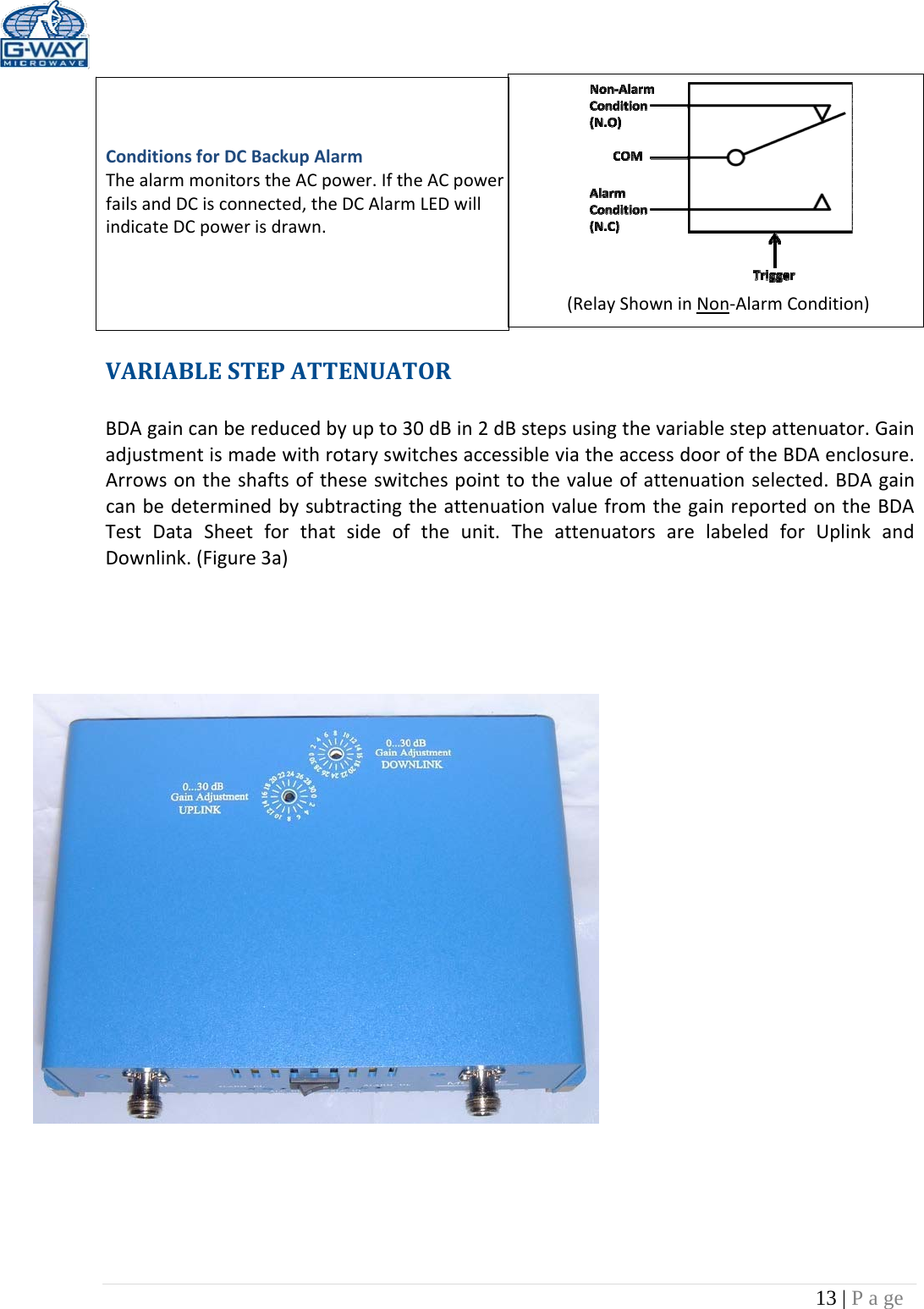
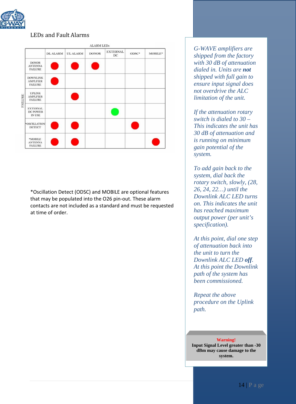
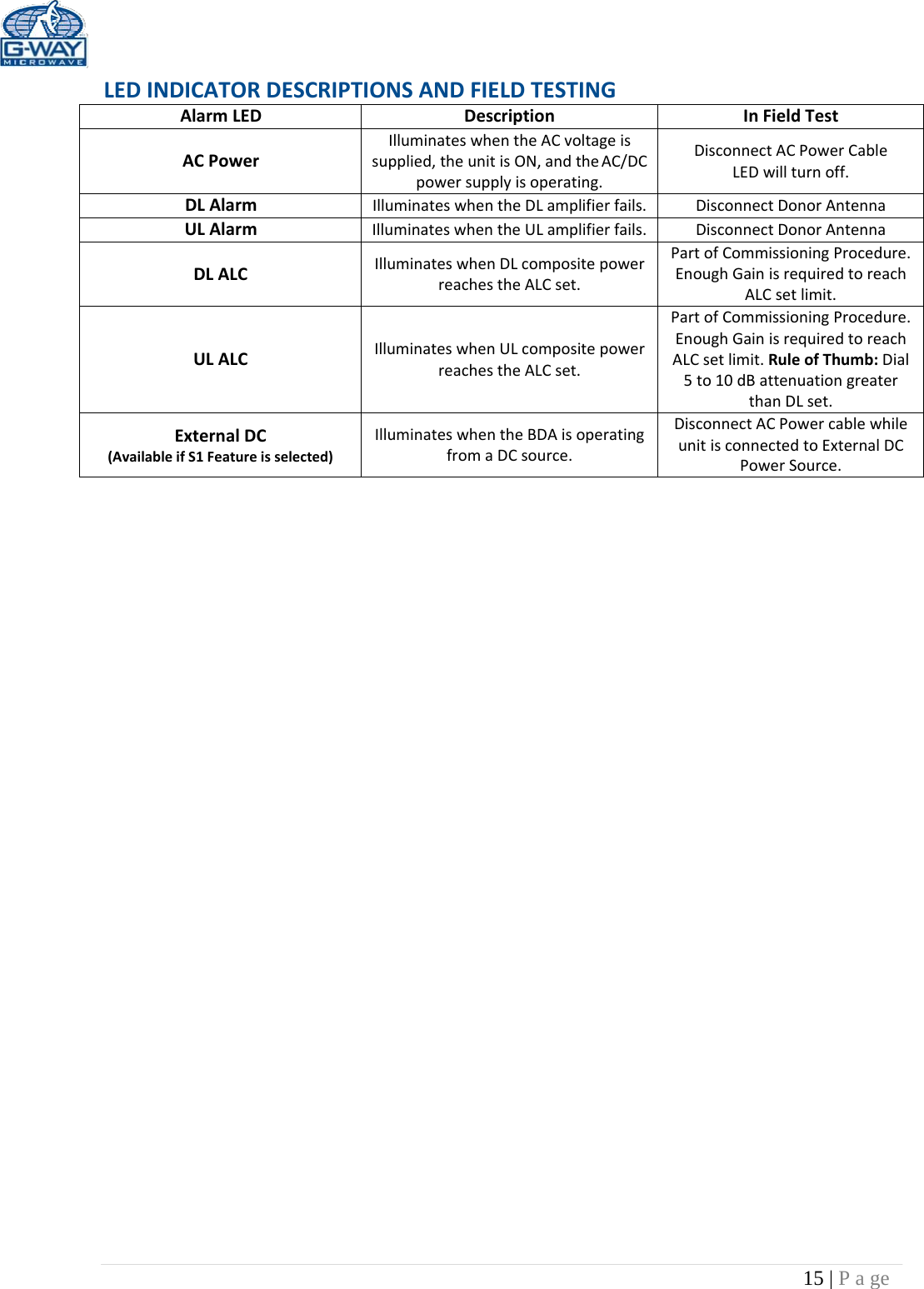
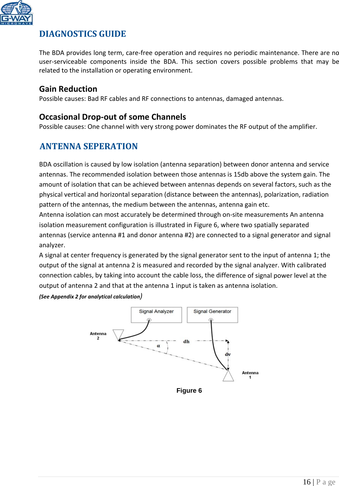
![12 | P a ge BDAOPERATIONALC(AutomaticLevelControl)Tominimizeintermodulationproducts,eachamplifierintheBDAcontainsanALCfeedbackloop.TheALCcircuitsensestheoutputpowerandlimitsittothefactorypresetlevelasspecifiedoneachproductspecification.EachamplifierintheBDAcontainsanALCfeedbackloop.TheALCcircuitsensestheoutputpowerandlimitsittothefactorypresetlevel.AredindicatorlampislocatedontheinteriorpaneloftheBDAandilluminateswhentheoutputpowerexceedstheALCsetpoint.ToestablishproperoperatinggainontheUplinkandDownlinkpaths,startwiththeDownlink.ObservetheredindicatorlampontheUplinkamplifier.Unitsareshippedwithmaximumattenuation.Decreaseattenuationonestepatatimeuntilthe[DOWNLINKALC]ledislit.Then,usingtheDownlinkstepattenuator,increasetheattenuationuntiltheLEDturnsoff.RepeattheprocessfortheUplink.Thelevelindicatorisaccurateto+/‐ 0.4dBoftheALCsetpoint.IfatestradioisunavailableduringcommissioningtotesttheactualUplinkpower,asaferuleofthumbonUplinkadjustmentistosetthegain10dBlowerthantheDownlinkpath.OperationoftheBDAatmaximumgainwithgreaterthan‐30dBmaveragepowerincidentoneitherBASEorMOBILEportcancausedamagetotheBDA.Figure2aConditionsforALCAlarmThealarmmonitorscurrentofbothuplinkanddownlinkamplifiers.Analarmconditionwilloccurifeitheruplinkordownlinkamplifiersareoveritscurrenttolerance/ALClimitation.ConditionsforUplink/DownlinkAlarmThesealarmsmonitorthestatusofthecorrespondingamplifierpath.IfeitheroftheseLEDsareon,andnootheralarmLEDare,thisisanindicationofamplifierfailure,pleasecontactG‐WaveforanRMA.ConditionsforDonorAlarmThealarmmonitorstheconnectionoftheBDAtothedonorantenna.Analarmconditionwilloccurifthereisadisconnectatthedonorantenna.DonorLED,UL/DLAmplifierLEDwillindicateandallamplifierswillshutdown.ConditionsforMobileAlarmThealarmmonitorsmobileantennaconditionstotheVSWR.Intheeventamobileantennafails,thiswillgeneratereflectedpowertotheamplifier.MobileAlarmandAmplifierULwillindicate.](https://usermanual.wiki/G-Way-Solutions/PS82070M/User-Guide-3626843-Page-12.png)