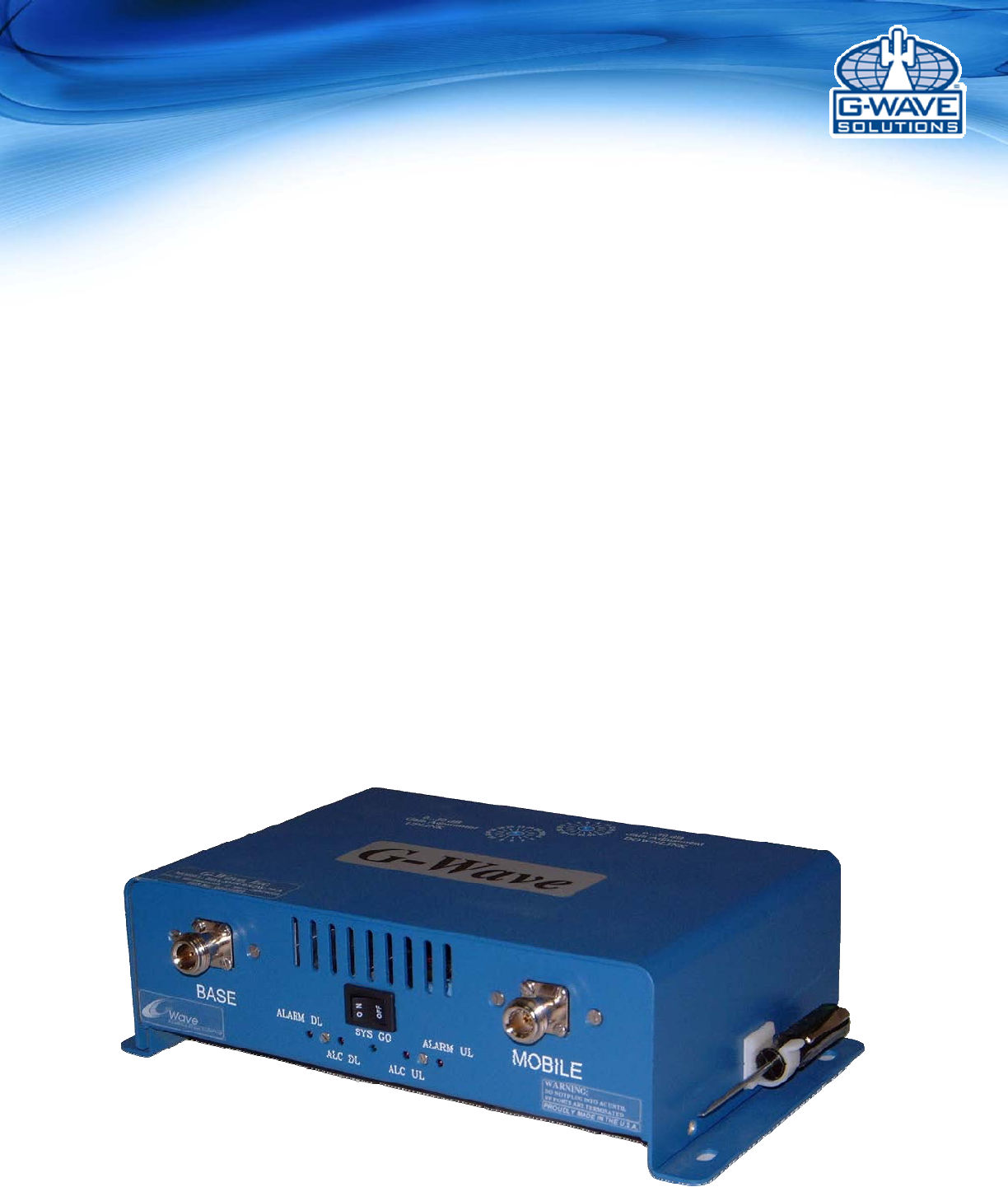
G Way Solutions PS82070M Industrial Signal Boosters User Manual BDA PSX 20 20 70 M manual
G-Way Microwave / G-Wave Industrial Signal Boosters BDA PSX 20 20 70 M manual
User Manual
Installation and
Operating Manual
BDA-PS8NEPS-20/20-70-M
BDA-PS8-20/20-70-M
BDA-PS7W-20/20-70-M
BDA-PS9-20/20-70-M
Single Band Mini Bi-Directional Amplifier

2 | P a ge
Table of Contents
SAFETYOPERATIONINSTRUCTIONS..........................................................................................................3
OVERVIEW...............................................................................................................................................................4
FCC NOTE .................................................................................................................................. 4
IC NOTE ...................................................................................................................................... 4
NOTE ........................................................................................................................................... 4
RF EXPOSURE WARNING- FCC ............................................................................................. 4
GENERALOPERATIONALDESCRIPTION...................................................................................................5
ELECTRICALSPECIFICATIONS.......................................................................................................................6
MECHANICALSPECIFICATIONS.....................................................................................................................7
ENVIRONMENTALCONDITIONS....................................................................................................................7
AVAILABLE,OPTIONALFEATURES..............................................................................................................8
ALARM CONDITIONS .............................................................................................................. 8
BDACONNECTIONS.............................................................................................................................................9
BDA INSTALLATION ............................................................................................................. 10
MECHANICALOUTLINE..................................................................................................................................11
BDAOPERATION................................................................................................................................................12
VARIABLESTEPATTENUATOR...................................................................................................................13
LED INDICATOR DESCRIPTIONS AND FIELD TESTING ................................................ 15
DIAGNOSTICSGUIDE........................................................................................................................................16
ANTENNASEPERATION.................................................................................................................................16
APPENDIX1..........................................................................................................................................................17
APPENDIX2..........................................................................................................................................................18
3 | P a ge
SAFETYOPERATIONINSTRUCTIONS
BEFOREUSE
Reviewthismanualandinsurethatallconditionsarecompatiblewiththe
amplifier'sspecifications.Safeoperationmaybeimpairedifthisequipmentis
notusedasintended.
GENERALDESCRIPTION
Thissymbolismarkedinthemanualanddenotesimportantsafetyoperation
instructions.Pleasereadcarefullybeforecontinuing.
Thisequipmentissuitableforawidevarietyofscientific,industrial,
laboratoryandcommunicationapplicationswherehighlevelsof
electromagneticRadioFrequency(RF)energyarerequired.Therefore,the
outputoftheamplifiermustbeterminatedtoanappropriateload,suchas
ahighpowerattenuator,dummyload,acommunicationorradiation
antenna.Usermustinsurethatradiatedenergydonotviolateregulatory
levelsofelectromagneticinterference.
PROTECTIVEGROUND
Thissymbolismarkedontheequipmentanddenotesprotectiveground
terminal.
Thisamplifierincludesprotectivegroundterminal.Theequipmentshouldn't
beusedifthisprotectionisimpaired.Thesuppliedpowercordmustbeused
alongwithanuninterruptedexternalpowersource.
HAZARDOUSLINEANDRFVOLTAGES
Thissymbolismarkedontheequipmentwheredangerousvoltagesare
present.Useextremecaution.
BothRFinputandoutputconnectorsshouldbeterminatedpriortothe
applicationoftheexternalACsource.Otherwise,contactwiththeRF
outputcenterpincanbedangerous.PlacetheamplifierintheOFFposition
priortoconnectinganddisconnectingRFoutputload.
ELECTROSTATICDISCHARGE(ESD)
ThissymbolismarkedontheequipmentwhereESDsensitivedevicesare
present.Donothandlewithouttheproperprotection.
MAINTENANCE
Maintenance,repairandcalibrationmustbeperformedbyqualified
personnelonly.Contactwiththeinternalamplifiercomponentsmaybe
dangerousevenwhentheequipmentisintheOFFposition.
ThisdenotesaconditionthatmaycausedamagetotheAmplifierif
procedureisnotcorrectlyperformed.Donotproceeduntiltheindicated
conditionsaremet.
FORCEDAIRCOOLING
Donotblocktheinletandoutletoftheinternalcoolingblowers.Otherwise
damagemayresulttotheamplifier.
CAUTION

4 | P a ge
OVERVIEW
TheBDAassemblyextendsthecoverageareaofradiocommunicationsinbuildingsandRF
shieldedenvironments.TheBDAhasdualRFpathstoextendcoverageintwodistinct
frequencybands.
Theunitfeatureslownoisefigureandwidedynamicrange.Itisbasedonaduplexedpath
configurationwithsharpoutofbandattenuationallowingimprovedisolationbetweenthe
receivingandtransmittingpaths.
FCCNOTE
ThisisaClassBdevice.TheproducthasbeentestedandfoundtocomplywiththeBooster
requirementsperFCCPart90.
TheBDA‐PS9‐20/20‐70‐MBDAhasbeentestedandfoundtocomplywiththeBoosterrequirements
perFCCPart90andPart24.
ICNOTE
TheproducthasbeentestedandfoundtocomplywiththeIndustryCanada(IC)RFExposure
Requirements,pursuanttoICRSS‐131.
https://www.ic.gc.ca/eic/site/smt‐gst.nsf/vwapj/cpc2105e.pdf/$FILE/cpc2105e.pdf
NOTE
TheManufacturer’sratedoutputpowerofthisequipmentisforsinglecarrieroperation.Forsituations
whenmultiplecarriersignalsarepresent,theratingwouldhavetobereducedby3.5dB,especially
wheretheoutputsignalisre‐radiatedandcancauseinterferencetoadjacentbandusers.Thispower
reductionistobebymeansofinputpowerorgainreductionandnotbyanattenuatorattheoutput
ofthedevice.
RFEXPOSUREWARNING
Anantennamustbeinstalledsoastoprovideaminimumseparationdistanceofatleast7.87inch(20
cm)betweentheindoorantennaconnectedtotheRFboosterandthehumanuser’sbodywithinthe
area.Thisassumesatypicalwide‐beamtypeantennawithgainof0‐2dBi,VSWR≤2:1,Zo=50ohms.
Use of unauthorized.antennas,cables and/or coupling devices not conforming with ERP/EIRP are not allowed.

5 | P a ge
GENERALOPERATIONALDESCRIPTION
TheBDADownlinkpathreceivesRFsignalsfromthebasestationandamplifiesandtransmitsthemto
thesubscriber.TheBDAUplinkpathreceivesRFsignalsfromthesubscriberandamplifiesand
transmitsthemtothebasestation.TheUplinkandDownlinkoccupytwodistinctfrequencybands.
Seetableonpage6forlistofbandsandcorrespondingbandcodes.Frequenciesapplicabletoyour
unitwillalsobeonunit’sspecificationsheet.
Thediplexerisolatesthepathsandrouteeachsignaltotheproperamplifyingchannel.
AnAutomaticLevelControl(ALC)allowsforoutputpowerlimiting.Avariablestepattenuatorgives0–
30dBofattenuationin2dBsteps.Theuseofthesecontrolsiscoveredinthe“OPERATION”section,
laterinthisdocument.
TheMini‐BDAcanbeusedasalineamplifier.Withanoptionalexternalbias‐tee,theMini‐BDAwill
functionwithpowercomingfromtheIn‐buildingantenna.
6 | P a ge
Table1
CODEUPLINKBAND DOWNLINKBAND
BDA‐PS7W‐20/20‐70‐M(US)788‐805MHz758‐775MHz
BDA‐PS7W‐20/20‐70‐M
BDA‐PS7‐20/20‐70‐M(Canada)798‐806MHz768‐776MHz
BDA‐PS8NEPS‐20/20‐70‐M(US)806‐816MHz851‐861MHz
BDA‐PS8‐20/20‐70‐M
BDA‐NPSPAC‐20/20‐70‐M
BDA‐SMR‐0.15/0.15W‐35‐E
BDA‐SMR‐0.5/0.5W‐70‐A
(Canada)
806‐824MHz851‐869MHz
BDA‐PS9‐20/20‐70‐M(US&Canada)896‐902MHz935‐941MHz
ELECTRICALSPECIFICATIONS
S
pecificationsTypica
l
FrequencyRangeSeeTable1
PassbandGain@minattenuation70dB
MaximumRFInputSignalLeve
l
‐30dBm
VariableStepAttenuatorRange
(2dBsteps)
0‐30dB
PassbandRipple±1.5dB
NoiseFigure@+25
Catmaxgain5.0dB
IP3[dBm]@2Tones+17dBm
Uplink
Downlink
+37dBm
+37dBm
CompositeOutputPower
(SingleChannel)
Uplink
Downlink
+20dBm
+20dBm
IsolationbetweenUp/DownLink+25dBm
Input/OutputImpedance105dB(Min.)
VSWR(Input/Output)50Ohms
PowerSupply1.5:1(Max)
110VAC/0.56Amp240VAC/0.28Amp
50to60HzAutoranging

7 | P a ge
MECHANICALSPECIFICATIONS:
Size:10x6.2x3.0inch
RFConnectors:N‐typeFemale
Weight:4.6Lbs.approx.
**Note:Mayvaryperunit,seespecformoreaccurateinformationspecifictoyourSKU
ENVIRONMENTALCONDITIONS
Theunitisdesignedforindoorapplications:
Operatingtemperature:‐30Cto+55C
Storagetemperature:‐50Cto+90C
StandardIndoorBDA’saredesignedtooperateinanindoorenvironment,
withintypicaloperatingtemperaturerangeof‐30Cto+55C,withnormal
airflowonheatdissipationsurfacesofthesystems.TheACpowersupply
shouldbeconditionedfornormalindoorapplianceapplications.
StandardIndoorBDA’sareNOTdesignedforoutdoorapplicationswheretheambient
temperatureisoutsidetherecommendedrangeorinsideanadditionalenclosure.This
willpreventnormalairflowonheatdissipationsurfacesofthesystems,damaging
AmplifiersandtheMainPowerSupply.
StandardIndoorBDA’sareNOTdesignedfortheusewithunstablepowersources,i.e.:
generators.Shouldtheseunitsfailduetoconditionsnotwithinspecifiedparameters,the
warrantywillvoid.
G‐WavemaysupplyBDA’swithadditionalprotectiondesignedforoutdoorapplications
uponrequest

8 | P a ge
AVAILABLE,OPTIONALFEATURES
Thefollowingoptionsareavailable,(pleasereviewthespecificationprovidedwiththeunit,toverify
thefeaturesincludedinyourBDA)
VisualAlarms
AllG‐Wavesystemsincludelocalvisualalarmsasastandard.Local
visualalarmsareLEDlightslocatedintheunitthatindicatevarious
failures.Foralistofcorrespondingalarms,pleaseseeVariable
GainAdjustmentandLEDIndicators.
DC28
PoweredDCOnly@+28VDC
ACSP
ACSurgeProtectionandDCLineConditioning(Requiredifpoweredbygenerator)
RM9
9‐Pinconnectortoenableremotealarmingviadrycontact.Alarmsinclude:UplinkAmplifierFailure,
DownlinkAmplifierFailure,UplinkALC,DownlinkALC.
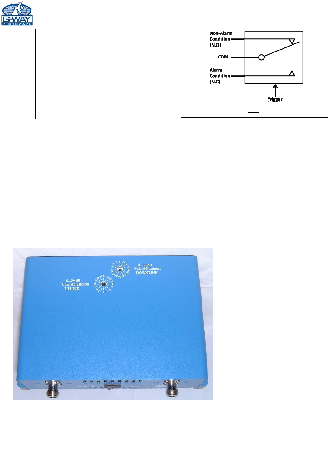
ALARM CONDITIONS
Thealarmmonitorsthecurrentofboththeuplinkanddownlinkamplifiers.Analarmconditionwill
occurifeithertheuplinkordownlinkamplifiersareoverorunderitscurrenttolerance.
Additionally,eachfailure/alarm/indicatorfromtheavailablefeaturesmaybemonitoredviaan
audiblealarmdrycontactconnector,3contactspereachalarm.ThefollowingdiagramshowsaNon
Alarmcondition.Ifanalarmoccursthetriggerwillswitchthepositionoftherelay,ashortwillbe
betweenCOMandN.C.
(
Relay Shown in Non-Alarm
9 | P a ge
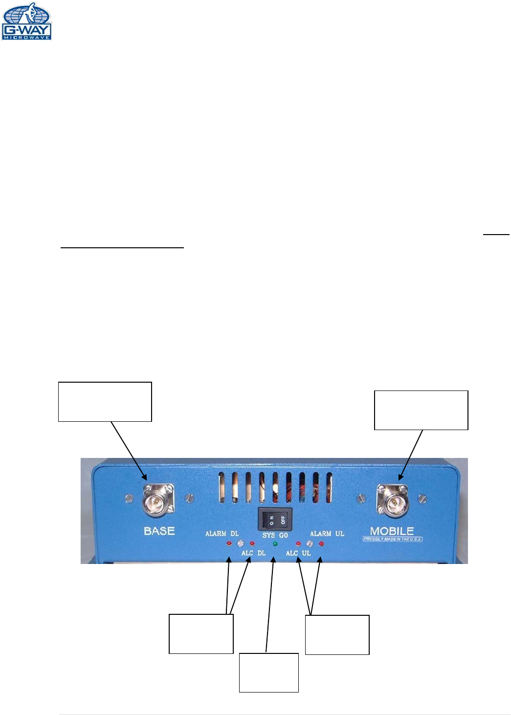
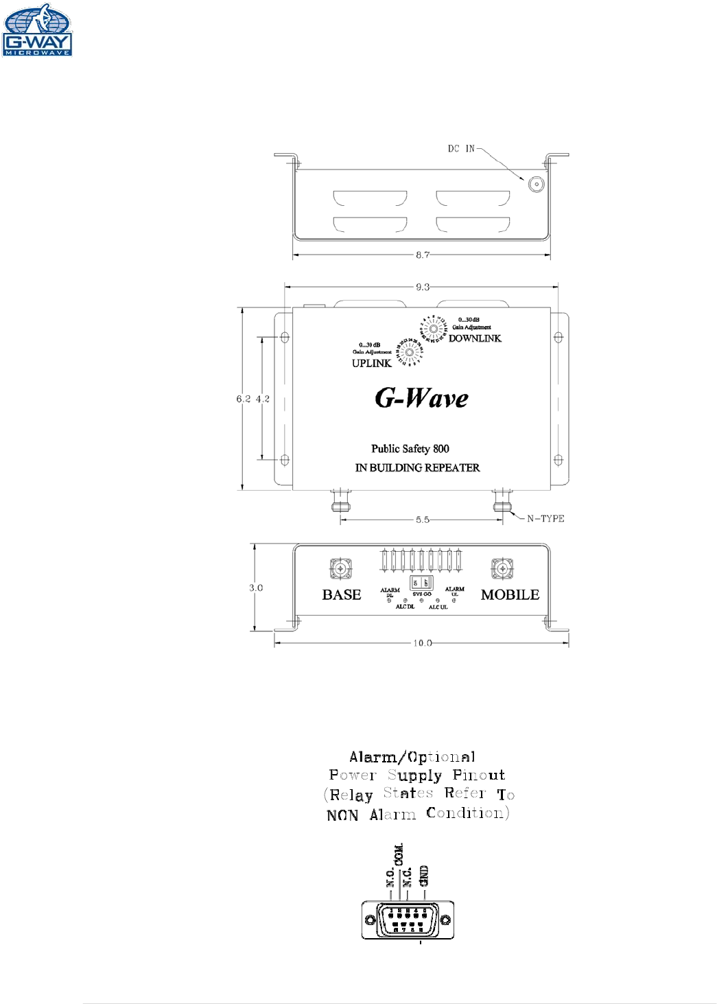
BDACONNECTIONS
TheBDAusesanexternalpowersupplywhichconnectsthroughasinglepin15VDCinputlocatedonthe
backoftheunit.
Aoptional9‐pinD‐Subconnectorprovidesfailurealarmoutputcontacts.
TheRFconnectionsaremadeviatwotype“N”femaleconnectors.TheRFconnectorlabeled“BASE”
mustbeconnectedtotheantennapointingtowardsthebasestation.TheRFconnectionlabeled
“MOBILE”mustbeconnectedtotheantennafacingtheareatobecoveredbytheBDA.
TheRFconnectionsmustbemadethroughcableswithcharacteristicimpedanceof50ohms.
Theisolationbetweenthebasestationantennaandthemobileantennashouldbeatleast15dB
higherthantheBDAgain.Isolationlessthanthisvaluecancausegainrippleacrosstheband.
IsolationequaltoorlessthantheBDAgainwillgiverisetooscillationswhichwillsaturatethe
amplifiersandpossiblycausedamagetotheBDA.
Connector from
Donor Antenna Connector to
DAS
DL Alarm
LEDs UL Alarm
LEDs
Power
On LED
10 | P a ge
BDA INSTALLATION
DONOTAPPLYA.C.POWERTOTHEBDAUNTILCABLESARECONNECTED
TOBOTHPORTSOFTHEBDAANDTHEANTENNAS.
1. MounttheBDAonthewallwiththeRFconnectorspointingDOWN.Usingappropriate
screwsandanchors,attachtheBDAtothewallatthefourmountingholesontheside
flanges.
2. Ensurethattheisolationbetweenthedonorantennaandtheserviceantennaisatleast15
dBgreaterthantheBDAgain.(UsethehigheroftheUplinkandDownlinkgainsreportedon
theBDAtestdatasheet).
3. ConnectthecablefromthedonorantennatotheBDAconnectorlabeled“BASE”andthe
cablefromtheserviceantennastotheBDAconnectorlabeled“MOBILE”.
4. Verifythatbothoftheattenuator’sarepositionedtoitsmaximumsetting(30dB)onthe
unit’sfrontpanel.
5. ConnectthepowercordtotheBDAandthentothepowersource.Verifythatthe“Power
ON”lampisilluminated.
InstallationoftheBDAisnowcomplete.Toadjustthegaincontrolstosuitthespecificsignal
environment,refertothenextsection(Operation)ofthemanual.
Note:Forrepeatinstallationsofexistingequipment,makesuretheattenuationis
positionedtoitsmaximumsetting(30dB).Afterverificationoftheattenuation,followthe
abovestepsstartingwithstep1.
11 | P a ge
MECHANICALOUTLINE

12 | P a ge
BDAOPERATION
ALC(AutomaticLevelControl)
Tominimizeintermodulationproducts,eachamplifierintheBDAcontainsanALCfeedbackloop.The
ALCcircuitsensestheoutputpowerandlimitsittothefactorypresetlevelasspecifiedoneach
productspecification.
EachamplifierintheBDAcontainsanALCfeedbackloop.TheALCcircuitsensestheoutputpowerand
limitsittothefactorypresetlevel.AredindicatorlampislocatedontheinteriorpaneloftheBDAand
illuminateswhentheoutputpowerexceedstheALCsetpoint.
ToestablishproperoperatinggainontheUplinkandDownlinkpaths,startwiththeDownlink.
ObservetheredindicatorlampontheUplinkamplifier.Unitsareshippedwithmaximumattenuation.
Decreaseattenuationonestepatatimeuntilthe[DOWNLINKALC]ledislit.Then,usingtheDownlink
stepattenuator,increasetheattenuationuntiltheLEDturnsoff.RepeattheprocessfortheUplink.
Thelevelindicatorisaccurateto+/‐ 0.4dBoftheALCsetpoint.Ifatestradioisunavailableduring
commissioningtotesttheactualUplinkpower,asaferuleofthumbonUplinkadjustmentistosetthe
gain10dBlowerthantheDownlinkpath.
OperationoftheBDAatmaximumgainwithgreaterthan‐30dBmaveragepowerincidentoneither
BASEorMOBILEportcancausedamagetotheBDA.
Figure2a
ConditionsforALCAlarm
Thealarmmonitorscurrentofbothuplinkand
downlinkamplifiers.Analarmconditionwilloccur
ifeitheruplinkordownlinkamplifiersareoverits
currenttolerance/ALClimitation.
ConditionsforUplink/DownlinkAlarm
Thesealarmsmonitorthestatusofthe
correspondingamplifierpath.Ifeitherofthese
LEDsareon,andnootheralarmLEDare,thisisan
indicationofamplifierfailure,pleasecontactG‐
WaveforanRMA.
ConditionsforDonorAlarm
ThealarmmonitorstheconnectionoftheBDAto
thedonorantenna.Analarmconditionwilloccur
ifthereisadisconnectatthedonorantenna.
DonorLED,UL/DLAmplifierLEDwillindicateand
allamplifierswillshutdown.
ConditionsforMobileAlarm
Thealarmmonitorsmobileantennaconditionsto
theVSWR.Intheeventamobileantennafails,this
willgeneratereflectedpowertotheamplifier.
MobileAlarmandAmplifierULwillindicate.
13 | P a ge
(RelayShowninNon‐AlarmCondition)
VARIABLESTEPATTENUATOR
BDAgaincanbereducedbyupto30dBin2dBstepsusingthevariablestepattenuator.Gain
adjustmentismadewithrotaryswitchesaccessibleviatheaccessdooroftheBDAenclosure.
Arrowsontheshaftsoftheseswitchespointtothevalueofattenuationselected.BDAgain
canbedeterminedbysubtractingtheattenuationvaluefromthegainreportedontheBDA
TestDataSheetforthatsideoftheunit.TheattenuatorsarelabeledforUplinkand
Downlink.(Figure3a)
ConditionsforDCBackupAlarm
ThealarmmonitorstheACpower.IftheACpower
failsandDCisconnected,theDCAlarmLEDwill
indicateDCpowerisdrawn.
LEDsandFaultAlarms
G-WAVE amplifiers are
shipped from the factory
with 30 dB of attenuation
dialed in. Units are not
shipped with full gain to
ensure input signal does
not overdrive the ALC
limitation of the unit.
If the attenuation rotary
switch is dialed to 30 –
This indicates the unit has
30 dB of attenuation and
is running on minimum
gain potential of the
system.
*OscillationDetect(ODSC)andMOBILEareoptionalfeatures
thatmaybepopulatedintotheO26pin‐out.Thesealarm
contactsarenotincludedasastandardandmustberequested
attimeoforder.
To add gain back to the
system, dial back the
rotary switch, slowly, (28,
26, 24, 22…) until the
Downlink ALC LED turns
on. This indicates the unit
has reached maximum
output power (per unit’s
specification).
At this point, dial one step
of attenuation back into
the unit to turn the
Downlink ALC LED off.
At this point the Downlink
path of the system has
been commissioned.
Repeat the above
procedure on the Uplink
path.
Warning!
Input Signal Level greater than -30
dBm may cause damage to the
system.
14 | P a ge

15 | P a ge
LEDINDICATORDESCRIPTIONSANDFIELDTESTING
AlarmLEDDescription InFieldTest
ACPower
IlluminateswhentheACvoltageis
supplied,theunitisON,andtheAC/DC
powersupplyisoperating.
DisconnectACPowerCable
LEDwillturnoff.
DLAlarm
IlluminateswhentheDLamplifierfails.DisconnectDonorAntenna
ULAlarm
IlluminateswhentheULamplifierfails.DisconnectDonorAntenna
DLALC
IlluminateswhenDLcompositepower
reachestheALCset.
PartofCommissioningProcedure.
EnoughGainisrequiredtoreach
ALCsetlimit.
ULALC
IlluminateswhenULcompositepower
reachestheALCset.
PartofCommissioningProcedure.
EnoughGainisrequiredtoreach
ALCsetlimit.RuleofThumb:Dial
5to10dBattenuationgreater
thanDLset.
ExternalDC
(AvailableifS1Featureisselected)
IlluminateswhentheBDAisoperating
fromaDCsource.
DisconnectACPowercablewhile
unitisconnectedtoExternalDC
PowerSource.
16 | P a ge
DIAGNOSTICSGUIDE
TheBDAprovideslongterm,care‐freeoperationandrequiresnoperiodicmaintenance.Thereareno
user‐serviceablecomponentsinsidetheBDA.Thissectioncoverspossibleproblemsthatmaybe
relatedtotheinstallationoroperatingenvironment.
GainReduction
Possiblecauses:BadRFcablesandRFconnectionstoantennas,damagedantennas.
OccasionalDrop‐outofsomeChannels
Possiblecauses:OnechannelwithverystrongpowerdominatestheRFoutputoftheamplifier.
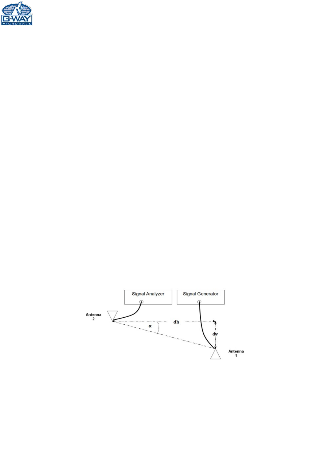
ANTENNASEPERATION
BDAoscillationiscausedbylowisolation(antennaseparation)betweendonorantennaandservice
antennas.Therecommendedisolationbetweenthoseantennasis15dbabovethesystemgain.The
amountofisolationthatcanbeachievedbetweenantennasdependsonseveralfactors,suchasthe
physicalverticalandhorizontalseparation(distancebetweentheantennas),polarization,radiation
patternoftheantennas,themediumbetweentheantennas,antennagainetc.
Antennaisolationcanmostaccuratelybedeterminedthroughon‐sitemeasurementsAnantenna
isolationmeasurementconfigurationisillustratedinFigure6,wheretwospatiallyseparated
antennas(serviceantenna#1anddonorantenna#2)areconnectedtoasignalgeneratorandsignal
analyzer.
Asignalatcenterfrequencyisgeneratedbythesignalgeneratorsenttotheinputofantenna1;the
outputofthesignalatantenna2ismeasuredandrecordedbythesignalanalyzer.Withcalibrated
connectioncables,bytakingintoaccountthecableloss,thedifferenceofsignalpowerlevelatthe
outputofantenna2andthatattheantenna1inputistakenasantennaisolation.
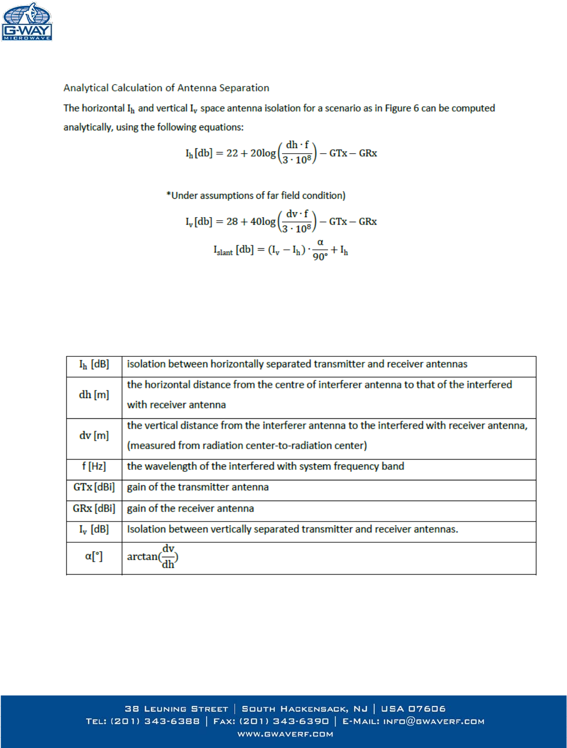
(SeeAppendix2foranalyticalcalculation
)
Figure 6
17 | P a ge
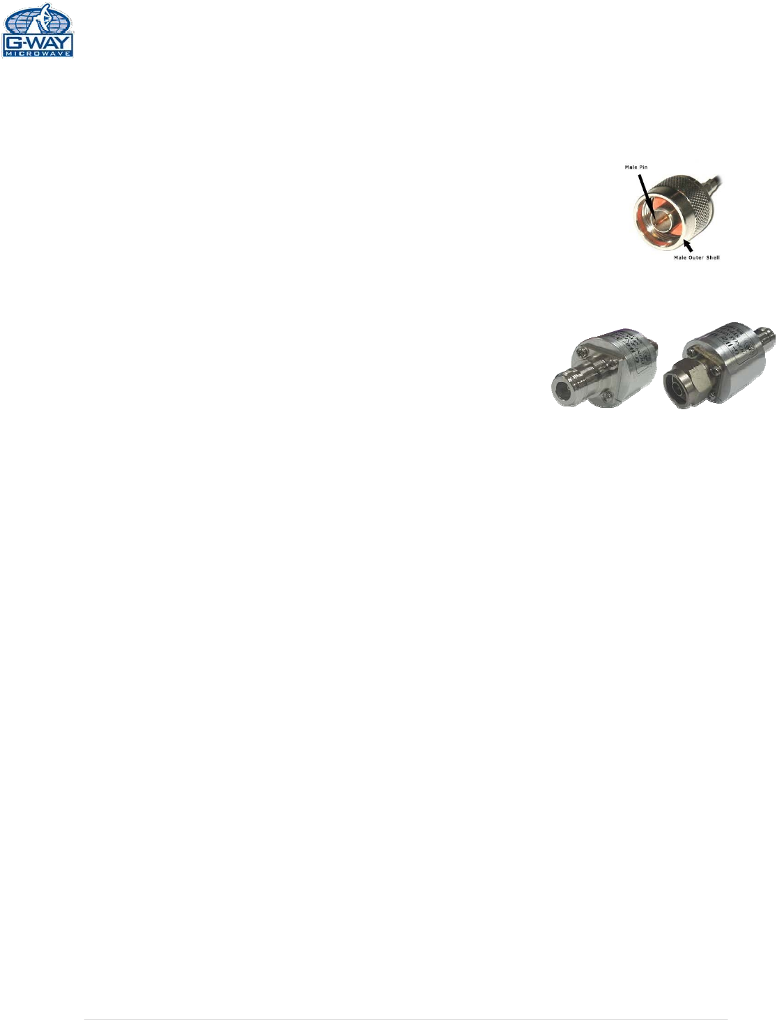
APPENDIX1
ConditionsforDonorAlarm(26‐pin)
ThisfunctionalityappliesonlyforaDonorantennawithaDC
short.AlarmmonitorstheconnectionoftheBDAtothedonor
antenna.Analarmconditionwilloccurifthereisadisconnect
atthedonorantenna.UplinkandDownlinkamplifierswillshut
down.DonorAlarm,CurrentDL,andCurrentULwillindicate.
Test for DC short between male pin and
outer shell of antenna connectors
Figure 7a
Ifthedonorantennadoesnotshortpleaseconnect
G‐Wave’sspecialDonorShortSimulator.
Pleasenote,ifyouintendtouseothercomponents(i.e.Lightning
Protector)betweenthebaseportanddonorantennamakesurethey
haveanopenshort.
NTypeFemale/Female
DonorShortSimulator
NTypeMale/Female
DonorShortSimulator
Figure7b
ConditionsforDCBackupAlarm
ThealarmmonitorstheACpower.IftheACpowerfails
andDCisconnected,theDCAlarmLEDwillindicateDC
power.
ConditionsforMobileAlarm
*OPTIONAL
ThealarmmonitorsmobileantennaconditionstotheVSWR.In
poorconditions,MobileAlarmandCurrentULwillindicate.
18
|
P a
g
e
APPENDIX2
AntennaSeparationvariabledefinitions: