G Way Solutions PS93790R DL/896-901 MHz UL/935-940 MHz User Manual
G-Way Microwave / G-Wave DL/896-901 MHz UL/935-940 MHz
UserManual.wiki
>
G Way Solutions
>
PS93790R User Manual
>
User Manual
Contents
1.
Manual
2.
User Manual
User Manual
Navigation menu
Upload a User Manual
Namespaces
Wiki Guide
HTML
PDF
Info
Views
User Manual
Discussion / Help
Navigation
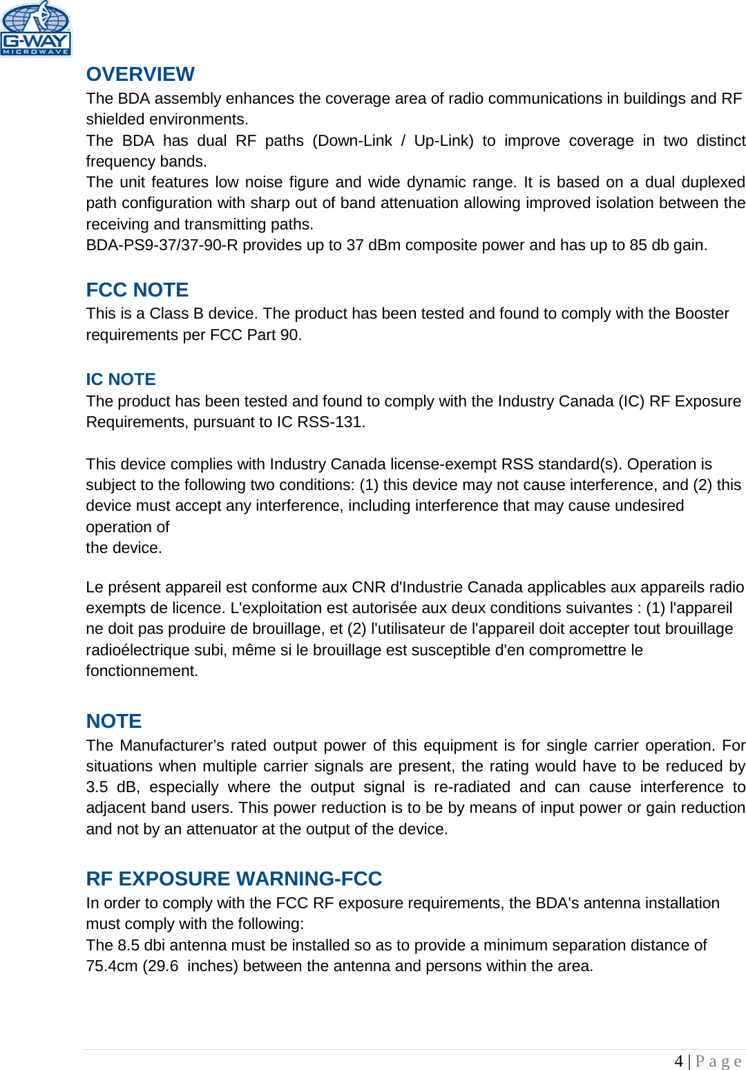
![6 | Page ELECTRICAL SPECIFICATIONS Down-Link Frequency Range 935-941 MHz Up-Link Frequency Range 896-902 MHz Pass band Gain @ Min. attenuation Up to 85 dB Variable Step Attenuator Range 2-dB steps 0-30 dB Maximum Input Signal Level -30 dBm Input/Output Impedance 50 Ohms VSWR (Input/Output) <1.5: 1 Power Supply @ 37dbm unit 110VAC/0.6Amps 220VAC/0.6Amps 50 to 60 Hz MECHANICAL SPECIFICATIONS Size 15”x19”x5.2” RF Connectors N-Type Female Weight 35 Lb. ENVIRONMENTAL CONDITIONS The unit is designed for indoor applications: Operating temperature: - 30°C to +55°C Storage temperature: - 40°C to +85°C Composite Output Power 25 dBm 27 dBm 33 dBm 37 dBm Gain Flatness [dB] ± 1.5 ± 2.0 ± 1.5 ± 1.5 Noise Figure [dB] 5.0 (Max.) 4.5 (Typ.) 5.0 (Max.) 4.5 (Typ.) 5.0 (Max.) 4.5 (Typ.) 5.5 (Max.) 5.0 (Typ.) Output Power ALC Set [dBm] UL: +25 ±1 DL: +25 ±1 UL: +27 ±1 DL: +27 ±1 UL: +33 ±1 DL: +33 ±1 UL: +37 ±1 DL: +37 ±1 3rd Order Intercept Point [dBm] UL: +46 (Typ.) DL: +46 (Typ.) UL: +48 (Typ.) DL: +48 (Typ.) UL: +51 (Typ.) DL: +51 (Typ.) UL: +55 (Typ.) DL: +55 (Typ.)](https://usermanual.wiki/G-Way-Solutions/PS93790R.User-Manual/User-Guide-3217623-Page-6.png)
![7 | Page 15 Amp Fuse 15 Amp - 12 Volt Lead-Acid Battery 12 Volt Lead-Acid Battery + + + Battery of BDA - Optional Battery Back-Up Configuration Figure 2: Optional Battery Back-Up Configuration Output Composite Power Typical DC Current Draw @24VDC [A] Battery Back-Up Time [Hours] Recommend Battery Rated Capacity (20 Hour Rate) [Amp Hours] 37 dBm 3.55 4 17.75 8 35.5 12 53.25 24 106.5 33 dBm 2.47 4 12.35 8 24.7 12 37.05 24 74.1 31 dBm 2.35 4 11.75 8 23.5 12 35.25 24 70.5 27 dBm 2.1 4 10.5 8 21 12 31.5 24 63](https://usermanual.wiki/G-Way-Solutions/PS93790R.User-Manual/User-Guide-3217623-Page-7.png)
![18 | Page APPENDIX 2 The horizontal Ih and vertical Iv space antenna isolation for a scenario as in Figure 6 can be computed analytically, using the following equations: Ih[db]=22 +20log dh f3108GTx GRx *Under assumptions of far field condition) Iv[db]=28 +40log dv f3108GTx GRx Islant [db]= (IvIh)90°+ Ih Antenna Separation variable definitions: Ih [dB] isolation between horizontally separated transmitter and receiver antennas dh [m] the horizontal distance from the centre of interferer antenna to that of the interfered with receiver antenna dv [m] the vertical distance from the interferer antenna to the interfered with receiver antenna, (measured from radiation centre-to-radiation centre) f [Hz] the wavelength of the interfered with system frequency band GTx [dBi] gain of the transmitter antenna GRx [dBi] gain of the receiver antenna Iv [dB] Isolation between vertically separated transmitter and receiver antennas. [°] arctan(dvdh)](https://usermanual.wiki/G-Way-Solutions/PS93790R.User-Manual/User-Guide-3217623-Page-18.png)