G Way Solutions PS93790R DL/896-901 MHz UL/935-940 MHz User Manual
G-Way Microwave / G-Wave DL/896-901 MHz UL/935-940 MHz
Contents
- 1. Manual
- 2. User Manual
User Manual
Installation and
Operating Manual
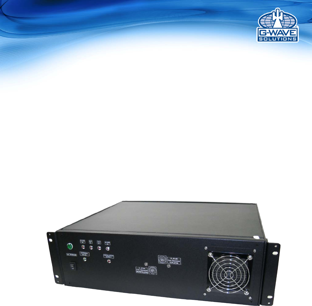
BDA-PS9-37/37-90-R
900 Band Bi-Directional Amplifier

2 | Page
Table of Contents
SAFETY OPERATION INSTRUCTIONS ................................................................................. 3
OVERVIEW ................................................................................................................................ 4
FCC NOTE .................................................................................................................................. 4
IC NOTE ...................................................................................................................................... 4
NOTE ........................................................................................................................................... 4
RF EXPOSURE WARNING-FCC .............................................................................................. 4
RF EXPOSURE WARNING- INDUSTRY CANADA .............................................................. 5
GENERAL DESCRIPTION ....................................................................................................... 5
ELECTRICAL SPECIFICATIONS ............................................................................................ 6
MECHANICAL SPECIFICATIONS .......................................................................................... 6
ENVIRONMENTAL CONDITIONS ......................................................................................... 6
MECHANICAL OUTLINE......................................................................................................... 8
CONNECTIONS ......................................................................................................................... 9
AVAILABLE, OPTIONAL FEATURES ................................................................................. 10
ALARM CONDITIONS ............................................................................................................ 11
VARIABLE GAIN ADJUSTMENT AND LED INDICATORS ............................................. 12
INSTALLATION ...................................................................................................................... 13
OPERATION ............................................................................................................................. 14
DIAGNOSTICS GUIDE ........................................................................................................... 15
ANTENNA SEPERATION ....................................................................................................... 15
APPENDIX 1 ............................................................................................................................. 16
APPENDIX 2 ............................................................................................................................. 18
3 | Page
SAFETY OPERATION INSTRUCTIONS
BEFORE USE
Review this manual and insure that all conditions are compatible with
the amplifier's specifications. Safe operation may be impaired if this
equipment is not used as intended.
GENERAL DESCRIPTION
This symbol is marked in the manual and denotes important safety
operation instructions. Please read carefully before continuing.
This equipment is suitable for a wide variety of scientific, industrial,
laboratory and communication applications where high levels of
electromagnetic Radio Frequency (RF) energy are required.
Therefore, the output of the amplifier must be terminated to an
appropriate load, such as a high power attenuator, dummy load, a
communication or radiation antenna. User must insure that radiated
energy do not violate regulatory levels of electromagnetic interference.
PROTECTIVE GROUND
This symbol is marked on the equipment and denotes protective ground
terminal.
This amplifier includes protective ground terminal. The equipment
shouldn't be used if this protection is impaired. The supplied power cord
must be used along with an uninterrupted external power source.
HAZARDOUS LINE AND RF VOLTAGES
This symbol is marked on the equipment where dangerous voltages are
present. Use extreme caution.
Both RF input and output connectors should be terminated prior to the
application of the external AC source. Otherwise, contact with the
RF output center pin can be dangerous. Place the amplifier in the
OFF position prior to connecting and disconnecting RF output load.
ELECTROSTATIC DISCHARGE (ESD)
This symbol is marked on the equipment where ESD sensitive devices
are present. Do not handle without the proper protection.
MAINTENANCE
Maintenance, repair and calibration must be performed by qualified
personnel only. Contact with the internal amplifier components maybe
dangerous even when the equipment is in the OFF position.
CAUTION This denotes a condition that may cause damage to the Amplifier if
procedure is not correctly performed. Do not proceed until the
indicated conditions are met.
FORCED AIR COOLING
Do not block the inlet and outlet of the internal cooling blowers.
Otherwise damage may result to the amplifier.

4 | Page
OVERVIEW
The BDA assembly enhances the coverage area of radio communications in buildings and RF
shielded environments.
The BDA has dual RF paths (Down-Link / Up-Link) to improve coverage in two distinct
frequency bands.
The unit features low noise figure and wide dynamic range. It is based on a dual duplexed
path configuration with sharp out of band attenuation allowing improved isolation between the
receiving and transmitting paths.
BDA-PS9-37/37-90-R provides up to 37 dBm composite power and has up to 85 db gain.
FCC NOTE
This is a Class B device. The product has been tested and found to comply with the Booster
requirements per FCC Part 90.
IC NOTE
The product has been tested and found to comply with the Industry Canada (IC) RF Exposure
Requirements, pursuant to IC RSS-131.
This device complies with Industry Canada license-exempt RSS standard(s). Operation is
subject to the following two conditions: (1) this device may not cause interference, and (2) this
device must accept any interference, including interference that may cause undesired
operation of
the device.
Le présent appareil est conforme aux CNR d'Industrie Canada applicables aux appareils radio
exempts de licence. L'exploitation est autorisée aux deux conditions suivantes : (1) l'appareil
ne doit pas produire de brouillage, et (2) l'utilisateur de l'appareil doit accepter tout brouillage
radioélectrique subi, même si le brouillage est susceptible d'en compromettre le
fonctionnement.
NOTE
The Manufacturer’s rated output power of this equipment is for single carrier operation. For
situations when multiple carrier signals are present, the rating would have to be reduced by
3.5 dB, especially where the output signal is re-radiated and can cause interference to
adjacent band users. This power reduction is to be by means of input power or gain reduction
and not by an attenuator at the output of the device.
RF EXPOSURE WARNING-FCC
In order to comply with the FCC RF exposure requirements, the BDA's antenna installation
must comply with the following:
The 8.5 dbi antenna must be installed so as to provide a minimum separation distance of
75.4cm (29.6 inches) between the antenna and persons within the area.

5 | Page
RF EXPOSURE WARNING- INDUSTRY CANADA
.
This system has been evaluated for RF Exposure per RSS-102 and is in compliance with the
limits specified by Health Canada Safety Code 6. The 8.5 dbi antenna must be installed so as
to provide a minimum separation distance of 87.3 cm (34.37 inches) between the antenna
and persons within the area.
L’exposition aux radiofréquences de ce système a été évaluée selon la norme RSS-102 et est
jugée conforme aux limites établies par le Code de sécurité 6 de Santé Canada. Le système
doit être installé à une distance minimale de 34.37 pouces (87.3 cm) séparant l’antenne
(8.5dbi) d’une personne présente en conformité avec les limites permises d’exposition du
grand public.
GENERAL DESCRIPTION
The downlink path of BDA receives RF signals from the base station, amplifies the signal and
transmits the signal, without changing the frequency, into a Distributed Antenna System at the
direction of the mobiles. The signal travels over a DAS medium that then dissipates the signal
to the Mobile subscribers. The uplink path receives RF signals at the Mobile side from the
DAS system, then amplifies it, and transmits the amplified signal (without changing the
frequency) to the base station.
This BDA supports Uplink and Downlink, 900 occupied distinct dedicated frequency bands.
The diplexer isolates the paths and route each signal to the proper amplifying channel.
An Automatic Level Control (ALC) allows for output power limiting. A variable step attenuator
gives 0 – 30 dB of attenuation in 2 dB steps. The use of these controls is covered in the
“OPERATION” section, later in this document.
6 | Page
ELECTRICAL SPECIFICATIONS
Down-Link Frequency Range
935-941 MHz
Up-Link Frequency Range
896-902 MHz
Pass band Gain @ Min. attenuation
Up to 85 dB
Variable Step Attenuator Range 2-dB
steps
0-30 dB
Maximum Input Signal Level
-30 dBm
Input/Output Impedance
50 Ohms
VSWR (Input/Output)
<1.5: 1
Power Supply @ 37dbm unit
110VAC/0.6Amps
220VAC/0.6Amps
50 to 60 Hz
MECHANICAL SPECIFICATIONS
Size
15”x19”x5.2”
RF
Connectors
N-Type Female
Weight
35 Lb.
ENVIRONMENTAL CONDITIONS
The unit is designed for indoor applications:
Operating temperature: - 30°C to +55°C
Storage temperature: - 40°C to +85°C
Composite Output
Power
25 dBm
27 dBm
33 dBm
37 dBm
Gain Flatness [dB]
± 1.5
± 2.0
± 1.5
± 1.5
Noise Figure [dB]
5.0 (Max.)
4.5 (Typ.)
5.0 (Max.)
4.5 (Typ.)
5.0 (Max.)
4.5 (Typ.)
5.5 (Max.)
5.0 (Typ.)
Output Power ALC Set
[dBm]
UL: +25 ±1
DL: +25 ±1
UL: +27 ±1
DL: +27 ±1
UL: +33 ±1
DL: +33 ±1
UL: +37 ±1
DL: +37 ±1
3rd Order Intercept Point
[dBm]
UL: +46
(Typ.)
DL: +46
(Typ.)
UL: +48
(Typ.)
DL: +48
(Typ.)
UL: +51
(Typ.)
DL: +51
(Typ.)
UL: +55
(Typ.)
DL: +55
(Typ.)
7 | Page
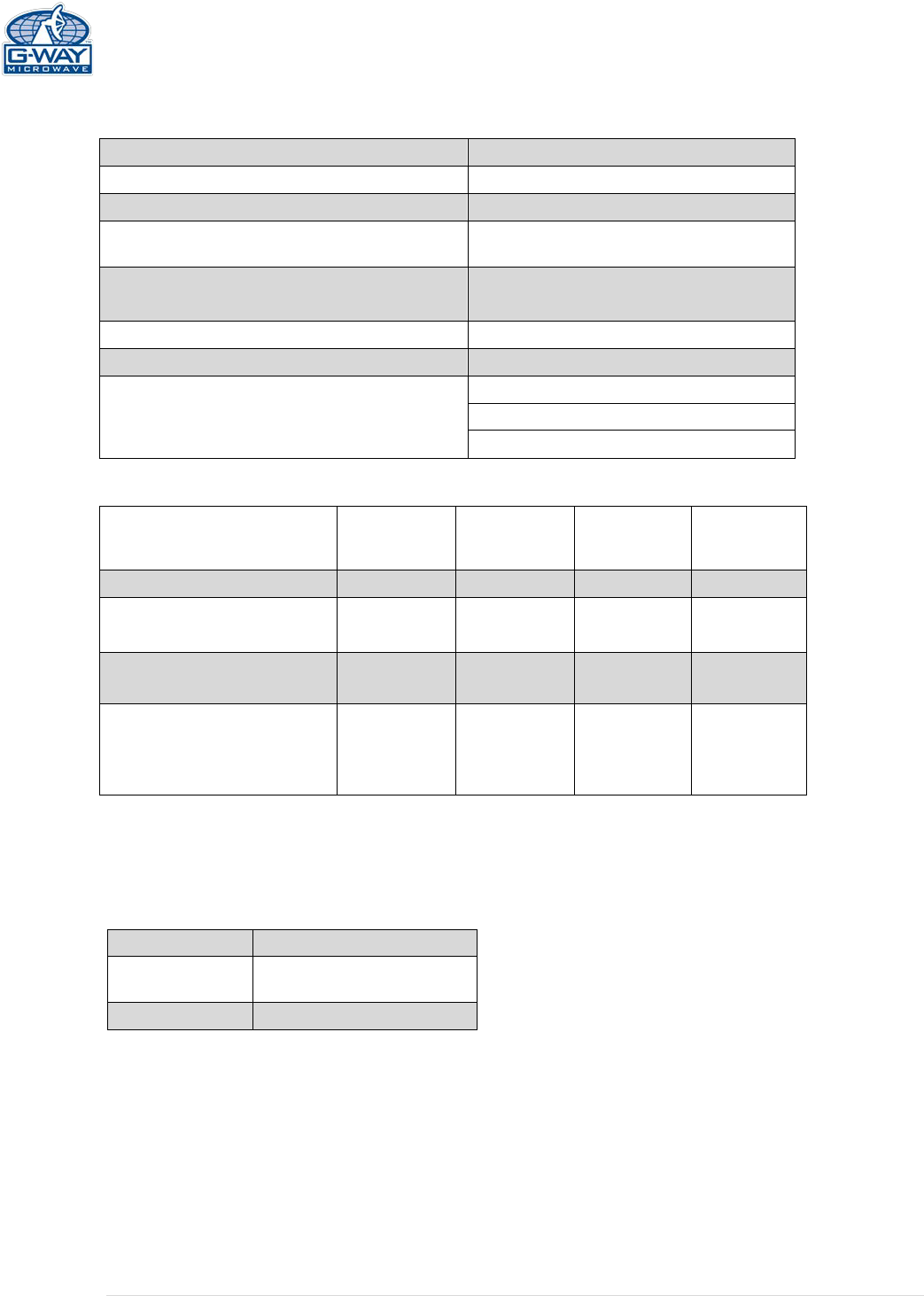
15 Amp Fuse
15 Amp
-
12 Volt
Lead-Acid
Battery
12 Volt
Lead-Acid
Battery
+
+
+ Battery of
BDA
-
Optional Battery Back-Up Configuration
Figure 2: Optional Battery Back-Up Configuration
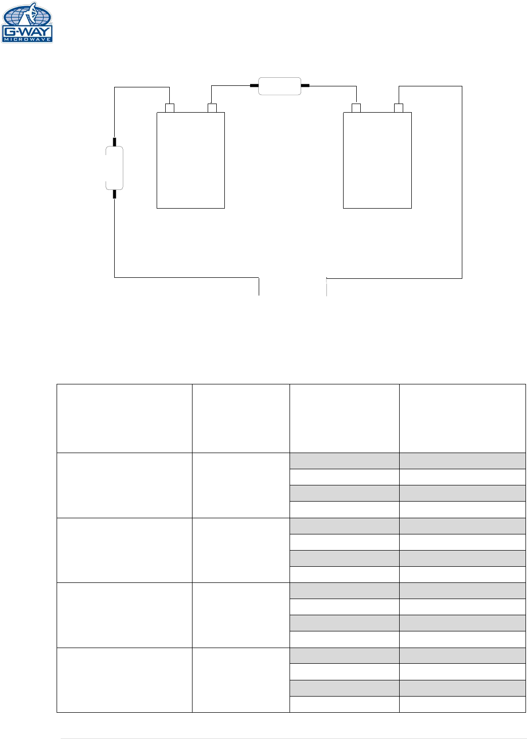
Output Composite
Power
Typical DC
Current Draw
@24VDC
[A]
Battery
Back-Up Time
[Hours]
Recommend Battery
Rated Capacity
(20 Hour Rate)
[Amp Hours]
37 dBm 3.55
4 17.75
8 35.5
12 53.25
24 106.5
33 dBm 2.47
4 12.35
8 24.7
12 37.05
24 74.1
31 dBm 2.35
4 11.75
8 23.5
12 35.25
24 70.5
27 dBm 2.1
4 10.5
8 21
12 31.5
24 63
8 | Page
Note: We do not guarantee specifications under Battery Back-Up power.
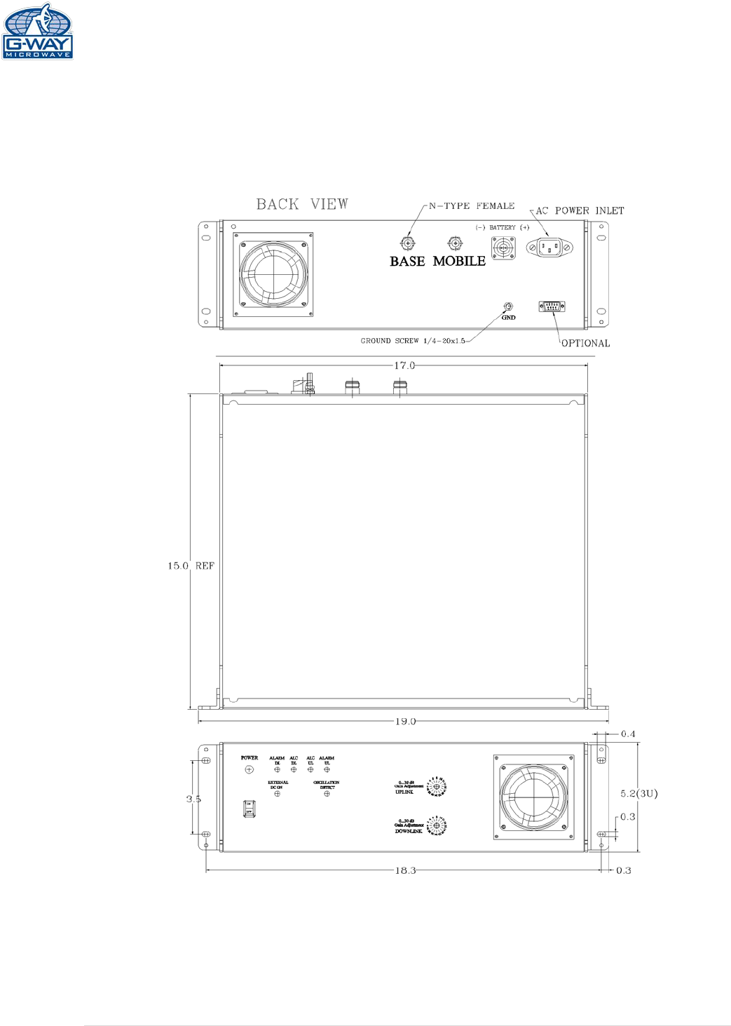
MECHANICAL OUTLINE
Figure 3: Mechanical Outline
9 | Page
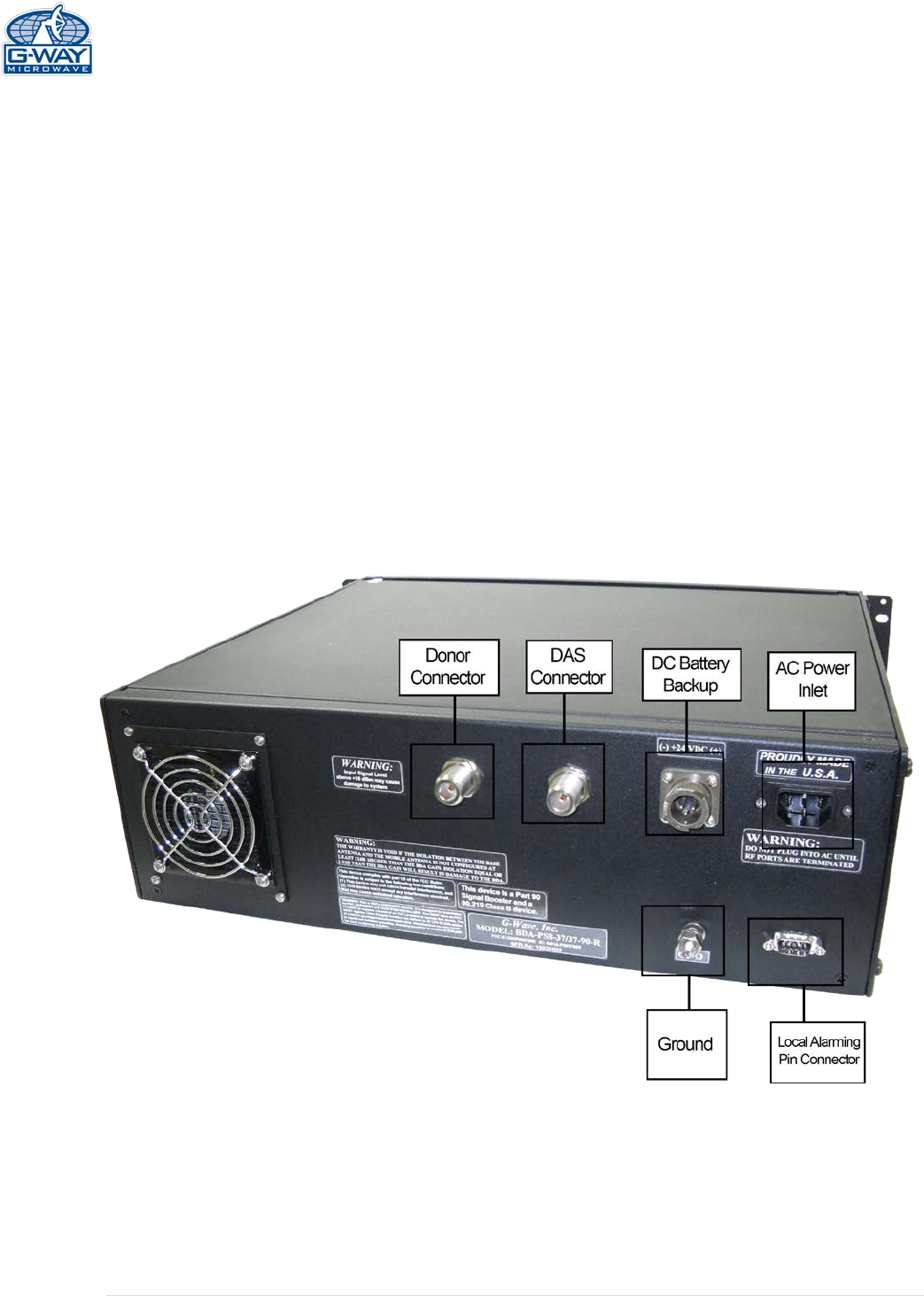
CONNECTIONS
The RF connections are made via two “N-type” female connectors. The RF connector labeled
“BASE” must be connected to the antenna pointing towards the base station. The RF
connection labeled “MOBILE” must be connected to the antenna / passive DAS facing the
area to be covered by the BDA.
The RF connections must be made through cables with characteristic impedance of 50 ohms.
The BDA AC power is accepted through a standard 3-wire male plug (IEC-320) with phase,
neutral and ground leads. The AC power is wired to a high efficiency DC switching power supply
which is CE and UL approved. The power supply runs the amplifiers and the LED indicators. The
metal enclosure of the BDA is connected to ground.
Additional monitoring connectors are available as described in the “Features” section.
Figure 4: Back Panel Connections
10 | Page
AVAILABLE, OPTIONAL FEATURES
The following options are available, (please review codes per features listed on the
product specification provided with the quote, to verify the features included in your
unit )
• Visual Alarms
All G-Wave systems include local visual alarms as a
standard. Local visual alarms are LED lights located on the
unit that indicate various failures. For a list of corresponding
alarms, please see Variable Gain Adjustment and LED
Indicators.
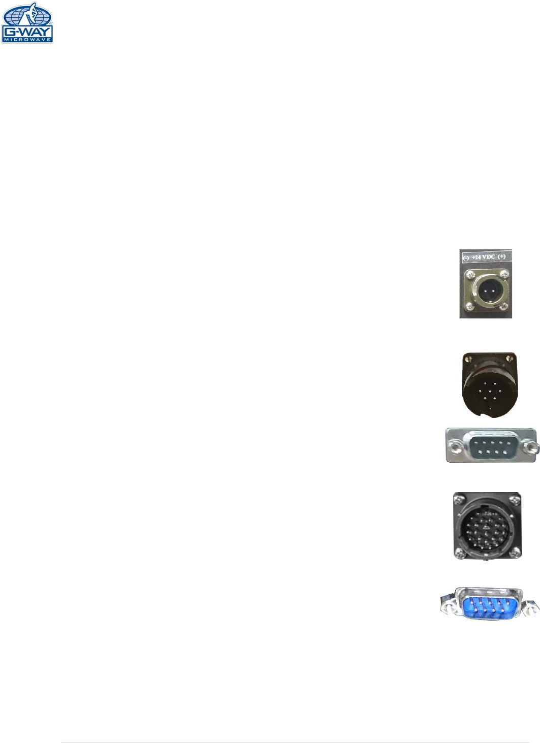
• DC Input Power Option (S1)
The BDA is equipped with both AC and DC voltage inputs for
power operation. This gives the flexibility of powering the BDA
with either an AC or DC source. If both sources are
connected, the BDA will automatically select the stronger
voltage source for power. (See page 7 for Composite Power Table)
• Local Alarming via dry contact 7-pin Connector (RM7)
A 7-Pin dry contact will be provided to hard wire into a
building’s alarm system. Dry contact will provide alarms for
ALC and amplifier failure.
• Local Alarming via dry contact 9-Pin Connector (RM9)
A 9-Pin dry contact will be provided to hard wire into a building’s
alarm system. Dry contact will provide alarms for ALC and
amplifier failure.
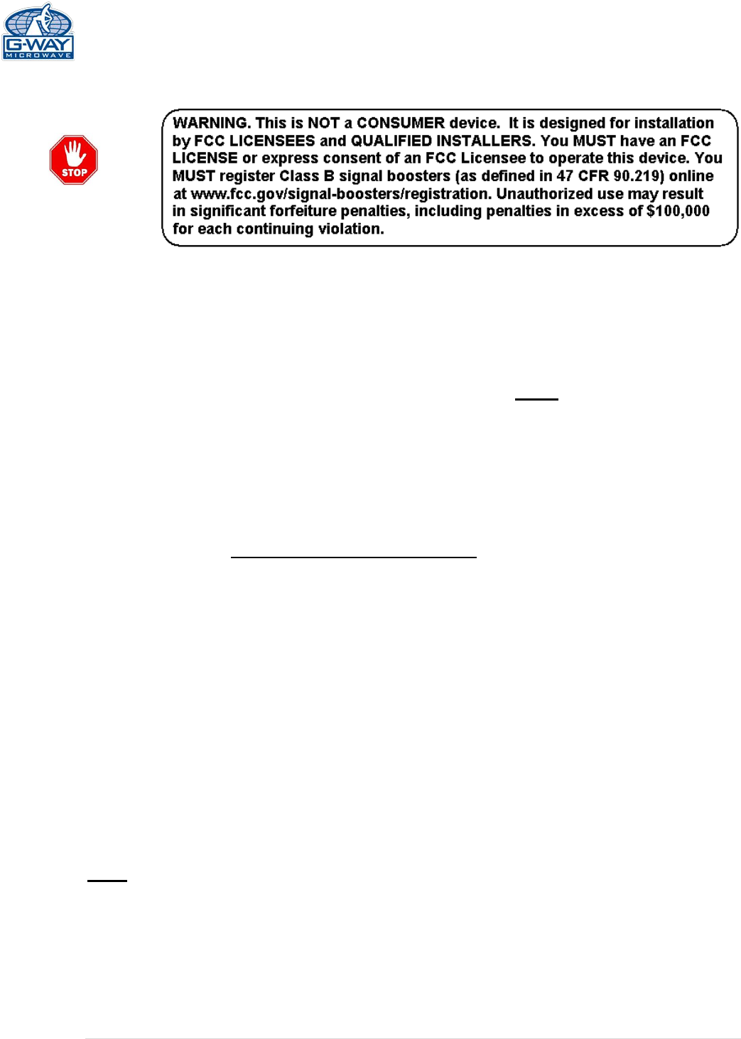
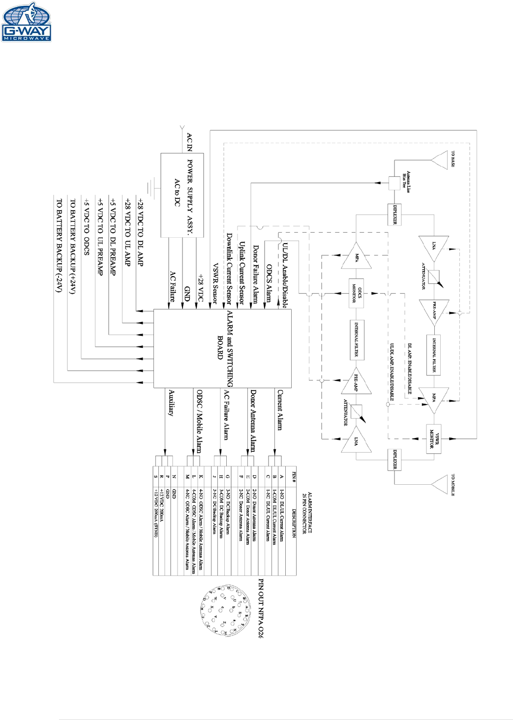
• Local Alarming via dry contact 26-Pin Connector (026)
A 26-Pin dry contact will be provided to hard wire into a
building’s alarm system. Dry contact will provide alarms for
ALC, amplifier failure, donor antenna failure and DC backup
failure. (See details in appendix 1)
• Oscillation Detector and Shutdown - ODSC / ODSCRM9
To minimize interference with other RF systems, this unit
includes an Oscillation detection module that continuously
monitors the BDA operation, in a case of Oscillation detection
inside the BDA, the detector will shut down all the amplifiers to
avoid RF interference with other systems in the area, when the
Oscillation condition passes or is resolved, the ODSC
operation will turn on all the amplifiers, returning to regular
operation. The ODSCRM9 module will allow Oscillation detect
/ display & shutdown of all amplifiers with local alarming via
11 | Page
dry contact connector. A red LED located on the front panel
(See figure 4) illuminates when oscillation is detected.
AVAILBLE, OPTIONAL FEATURES (Cont.)
• DC28
Powered DC Only @ + 28 VDC
• LGHT
Lightning Protection on UL/DL Ports
• RED
Red Enclosure to signify equipment is for public safety. Please verify your local requirements.
• ACSP
AC Surge Protection and DC Line Conditioning (Required if powered by generator)
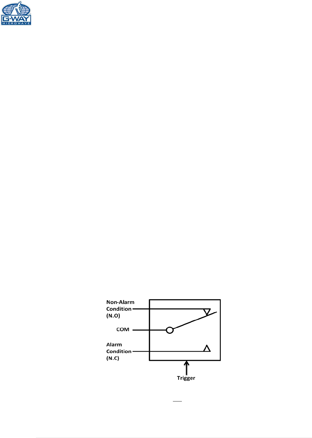
ALARM CONDITIONS
The alarm monitors the current of both the uplink and downlink amplifiers. An alarm condition
will occur if either the uplink or downlink amplifiers are over or under its current tolerance.
Additionaly, each failure/alarm/indicator from the available features can be monitored via an
alarm monitoring connector, 3 contacts per each alarm .The following diagram shows a Non
Alarm condition. If an alarm occurs the trigger will change the position of the relay, a short
will be between COM and N.C.
(
Relay Shown in Non-Alarm
)
12 | Page
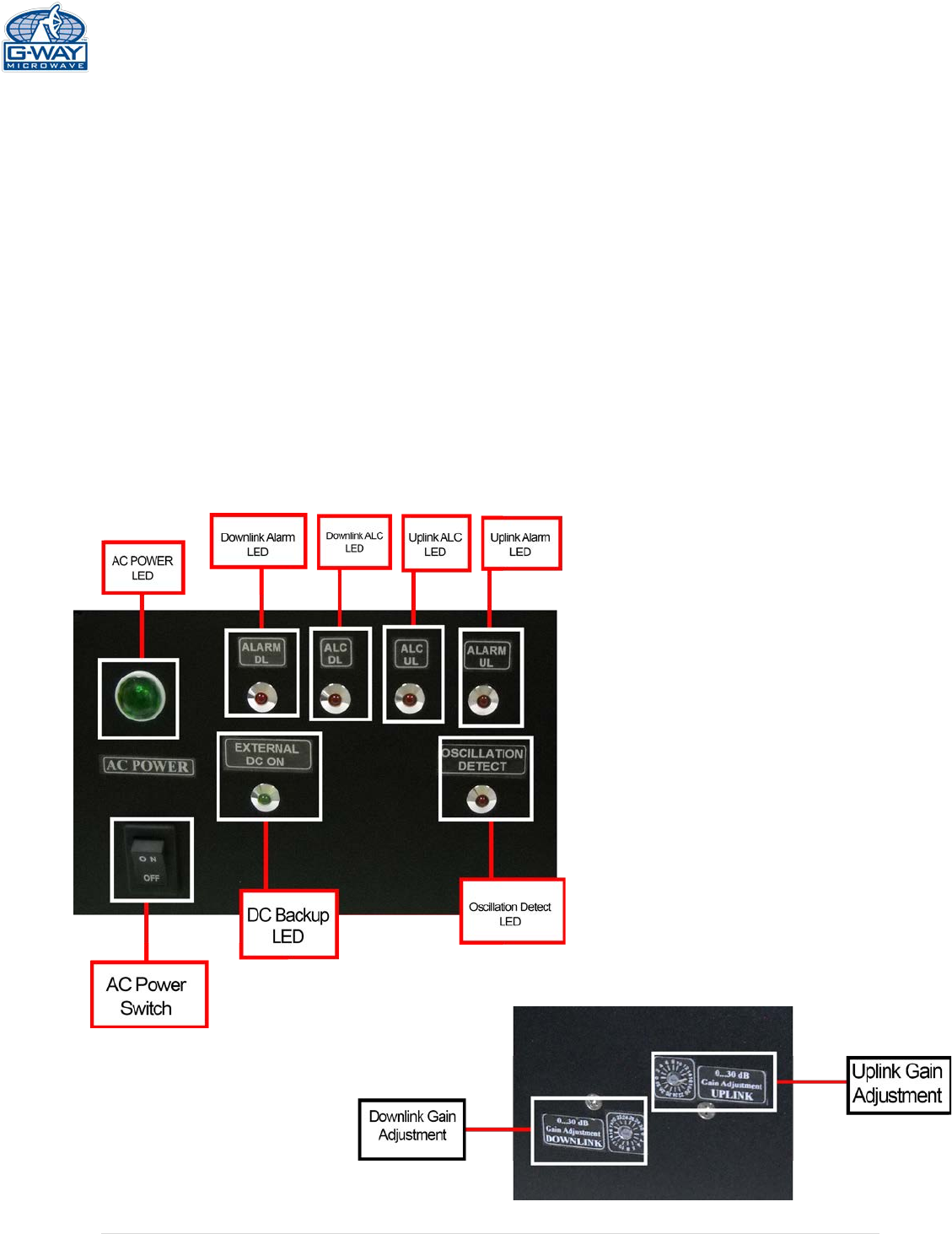
VARIABLE GAIN ADJUSTMENT AND LED INDICATORS
• AC Power LED - Illuminates when the AC voltage is supplied, the unit is ON, and the
AC/DC power supply is operating.
• DL ALC LED - Illuminates when DL composite power reaches the ALC set
• DL Alarm - Illuminates when the DL amplifier fails.
• UL ALC LED - Illuminates when UL composite power reaches the ALC set.
• UL Alarm - Illuminates when the UL amplifier fails.
• External DC LED (optional) - Illuminates when the BDA is operating from a DC source.
• Oscillation detection LED (optional) - Illuminates when oscillation is detected.
• Donor antenna alarm LED (optional) - Illuminates when Donor Antenna is disconnected.
• Mobile antenna alarm LED (optional) - Illuminates when the mobile port is disconnected.
• DL Manual Gain Attenuator- Is a switch used for DL gain attenuation
• UL Manual Gain Attenuator- Is a switch used for UL gain attenuation
Figure 5a:
Front Panel LED Indication
Figure 5b:
Front Panel Manual Attenuation
In 2 dB steps
13 | Page
INSTALLATION
DO NOT APPLY A.C. POWER TO THE UNIT UNTIL CABLES ARE
CONNECTED TO BOTH PORTS OF THE BDA AND THE ANTENNAS.
1. Place the BDA in the cabinet. Using appropriate screws and anchors or attach the BDA to
the wall at the four mounting holes on the side flanges (special version not shown in this
manual).
2. Ensure that the isolation between the base station antenna and the mobile antenna
should be at least 12 dB higher than the BDA gain (Use the higher of the Uplink and
Downlink gains reported on the BDA test data sheet).
Isolation less than this value can cause gain ripple across the band. Isolation equal to
or less than the BDA gain will give rise to oscillations which will saturate the amplifiers
and possibly cause damage to the BDA.
3. Connect the cable from the donor antenna to the BDA connector labeled “BASE” and the
cable from the service antennas to the BDA connector labeled “MOBILE”.
4. See main Panel of the BDA and verify that both of the Uplink and Downlink attenuation is
set to 30 dB via dial Attenuator.
5. Connect the AC power cord to the BDA and then to the power source. Verify that the
“Power ON” lamp is illuminated.
Installation of the BDA is now complete. To adjust the gain controls to suit the specific signal
environment, refer to the next section of the manual.
Note: For repeat installations of existing equipment, make sure the attenuation is
positioned to its maximum setting (30 dB). After verification attenuation, follow the
above steps starting with step 1.

14 | Page
OPERATION
Refer to Figure 4 & 5 for adjustment access location, connectors and labels.
Variable Step Attenuator
BDA gain that indicated in the spec can be reduced by up to 30 dB in 2 dB steps using the
variable step attenuator. Gain adjustment is made with rotary switches located on the front
panel of the BDA enclosure. Arrows on the shafts of these switches point to the value of
attenuation selected. BDA gain can be determined by subtracting the attenuation value from
the gain reported on the BDA Test Data Sheet for that side of the unit. The attenuators are
labeled for Uplink and Downlink.
ALC (Automatic Level Control)
To minimize intermodulation products, each amplifier in the BDA contains an ALC feedback
loop. The ALC circuit senses the output power and limits it to the factory preset level, as
indicated in the specification.
ALC function is located in each power amplifier. A red LED indicator located on the Front main
panel (see figure 5) illuminates when output power meets or exceeds the ALC preset point.
To establish proper operating gain on the Uplink and Downlink sides, start with the Downlink.
Observe the red LED indicator on the Downlink amplifier. Units are shipping with maximum
attenuation. Decrease attenuation one step at a time until the red LED is lit. Then, using the
Downlink step attenuator, increase the attenuation until the red LED goes off. Repeat the
process for the Uplink, and then repeat the process for the second band. This setup should be
done under RF signal transmit for either path the level indicator is accurate to +/- 0.4 dB of the
ALC set point.
Verify the downlink in-building signal strength and the uplink signal strength at donor antenna
meets requirements. Reduce the gain if needed.
Note: Operation of BDA-PS9-37/37-90-R at maximum gain with greater
than -30 dBm average power incidents on the MOBILE or BASE ports could
cause damage to the BDA.
15 | Page
DIAGNOSTICS GUIDE
The BDA provides long term, care-free operation and requires no periodic maintenance.
There are no user-serviceable components inside the BDA.
This section covers possible problems that may be related to the installation or operating
environment.
Gain Reduction
Possible causes: Defective RF cables and RF connections to antennas, damaged antenna or
Leaky cable.
Occasional Drop-out of some Channels
Possible causes: One channel with very strong power dominates the RF output of the
amplifier.
Excessive Intermodulation or Spurious
Possible causes: Amplifier oscillation caused by insufficient isolation between two antennas.
See antenna separation paragraph below.
ANTENNA SEPERATION
BDA oscillation is caused by low isolation (antenna separation) between donor antenna and
service antennas. The recommended isolation between those antennas is 15db above the
system gain. The amount of isolation that can be achieved between antennas depend
s on
several factors, such as the physical vertical and horizontal separation (distance between the
antennas), polarization, radiation pattern of the antennas, the medium between the
antennas, antenna gain etc.
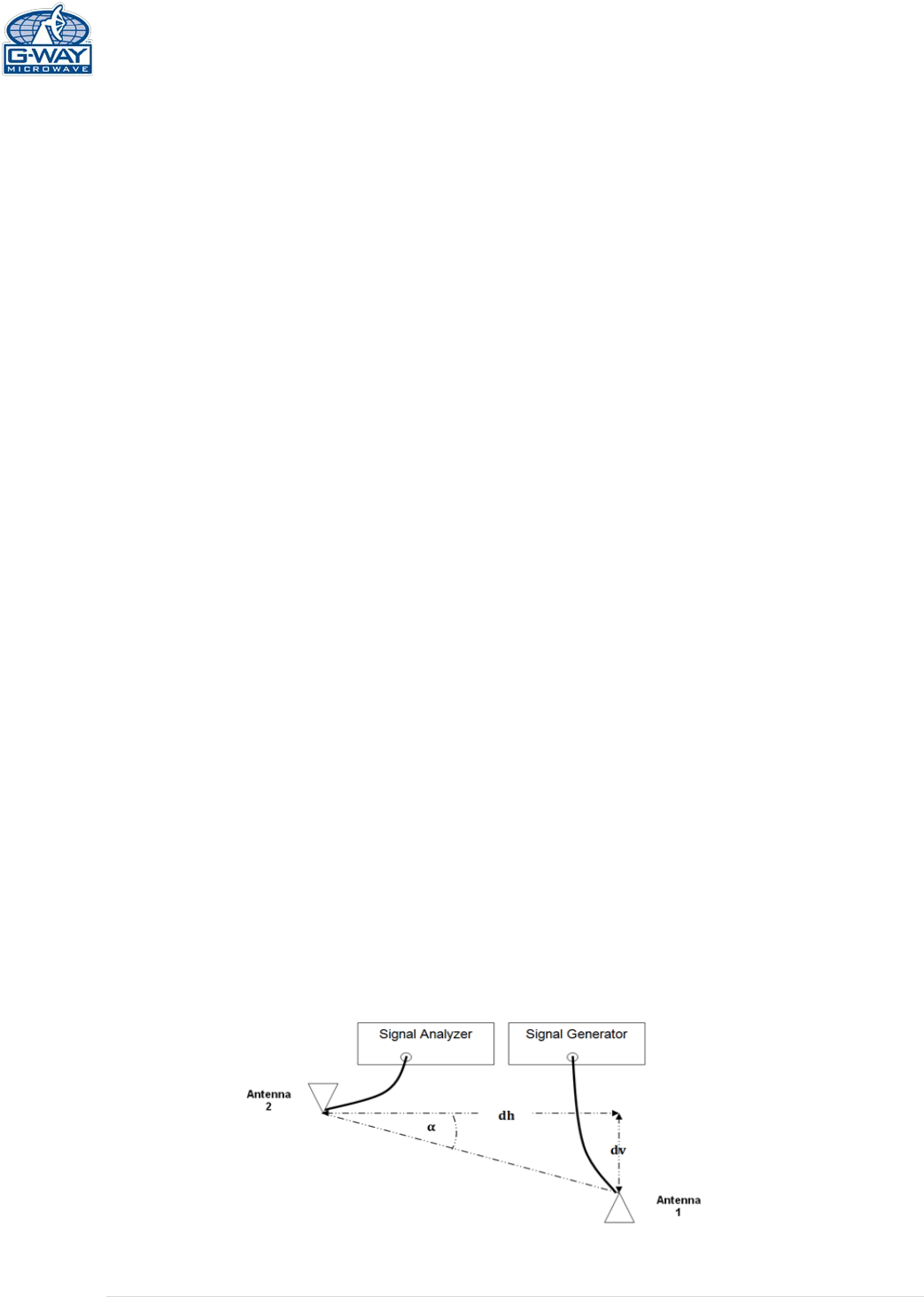
Antenna isolation can most accurately be det
ermined through on-site measurements An
antenna isolation measurement configuration is illustrated in Figure
6, where two spatially
separated antennas (service antenna #1 and donor antenna #2) are connected to a signal
generator and signal analyzer.
A sig
nal at centre frequency is generated by the signal generator sent to the input of antenna
1; the output of the signal at antenna 2 is measured and recorded by the signal analyzer.
With calibrated connection cables, by taking into account the cable loss, th
e difference of
signal power level at the output of antenna 2 and that at the antenna 1 input is taken as
antenna isolation.
(
See Appendix 2 for analytical calculation)
Figure 6
16 | Page
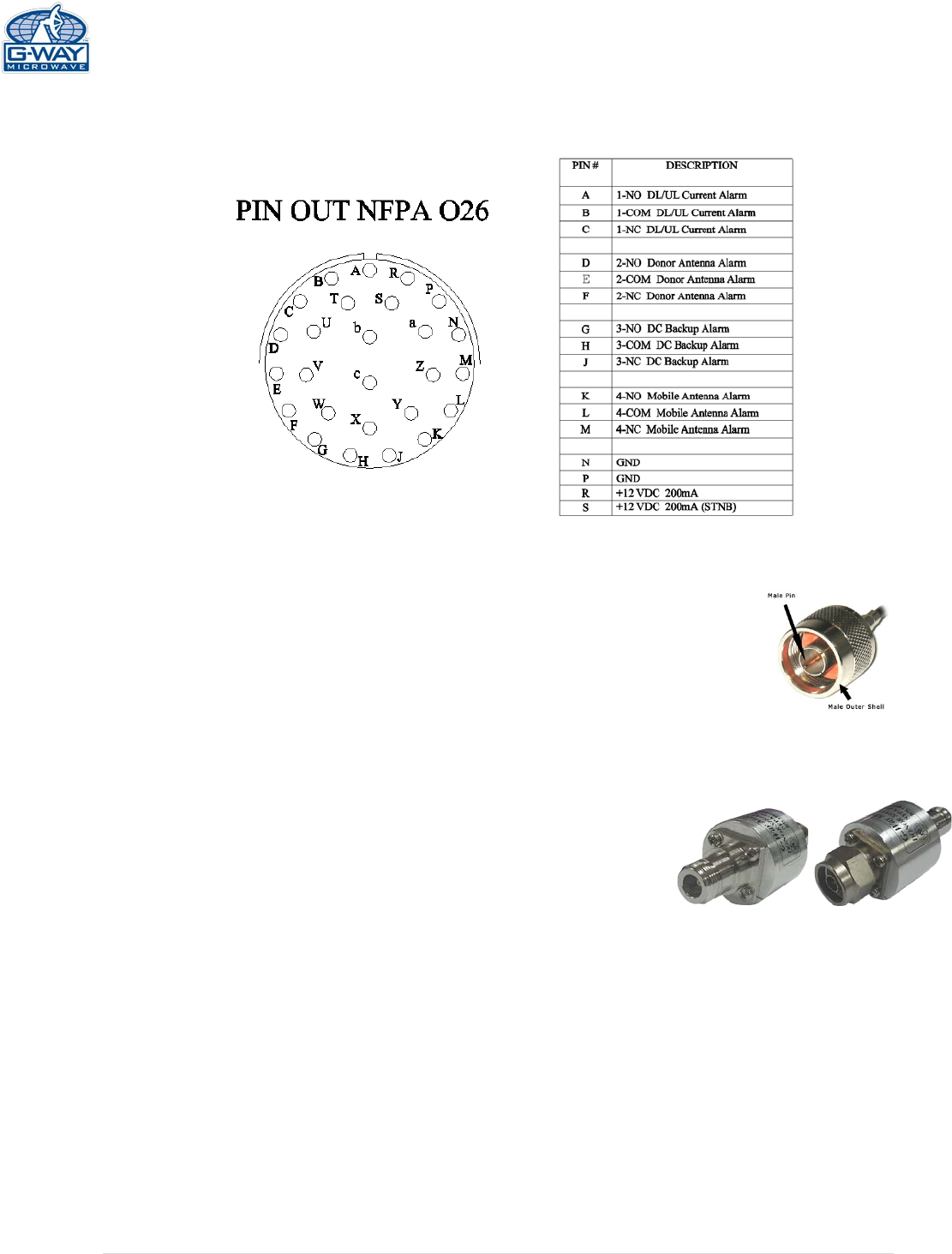
APPENDIX 1
26-Pin Connector
Conditions for Donor Alarm (26-pin)
This functionality applies only for a Donor antenna with a
DC short. Alarm monitors the connection of the BDA to
the donor antenna. An alarm condition will occur if there
is a disconnect at the donor antenna. Uplink and
Downlink amplifiers will shut down. Donor Alarm, Current
DL, and Current UL will indicate.
Test for DC short between male pin and
outer shell of antenna connectors
Figure 7a
If the donor antenna does not short please connect
G-Way’s special Donor Short Simulator.
Please note, if you intend to use other components (i.e.
Lightning Protector) between the base port and donor antenna
make sure they have an open short.
N Type Female/Female
Donor Short Simulator
N Type Male/Female
Donor Short Simulator
Figure 7b
Conditions for DC Backup Alarm
The alarm monitors the AC power. If the AC power
fails and DC is connected, the DC Alarm LED will
indicate DC power.
Conditions for Mobile Alarm *OPTIONAL
The alarm monitors mobile antenna conditions to
the VSWR. In poor conditions, Mobile Alarm and
Current UL will indicate.
17 | Page
Alarm Block Diagram
18 | Page
APPENDIX 2
The horizontal Ih and vertical Iv space antenna isolation for a scenario as in Figure 6 can be
computed analytically, using the following equations:
Ih[db]=22 +20log dh f
3108GTx GRx
*Under assumptions of far field condition)
Iv[db]=28 +40log dv f
3108GTx GRx
Islant [db]= (IvIh)
90°+ Ih
Antenna Separation variable definitions:
Ih [dB]
isolation between horizontally separated transmitter and receiver antennas
dh
[m]
the horizontal distance from the centre of interferer antenna to that of the
interfered with receiver antenna
dv
[m]
the vertical distance from the interferer antenna to the interfered with receiver
antenna, (measured from radiation centre-to-radiation centre)
f [Hz]
the wavelength of the interfered with system frequency band
GTx [dBi]
gain of the transmitter antenna
GRx [dBi]
gain of the receiver antenna
Iv [dB]
Isolation between vertically separated transmitter and receiver antennas.
[
°
]
arctan(dv
dh)