GE Analytical Instruments SIEVERSM9 Total Organic Carbon Analyzer User Manual DLM 77000 01 EN MC9 MC2
GE Analytical Instruments, Inc. Total Organic Carbon Analyzer DLM 77000 01 EN MC9 MC2
UserManual.wiki
>
GE Analytical Instruments
>
SIEVERSM9 User Manual
User Manual
Navigation menu
Upload a User Manual
Namespaces
Wiki Guide
HTML
PDF
Info
Views
User Manual
Discussion / Help
Navigation


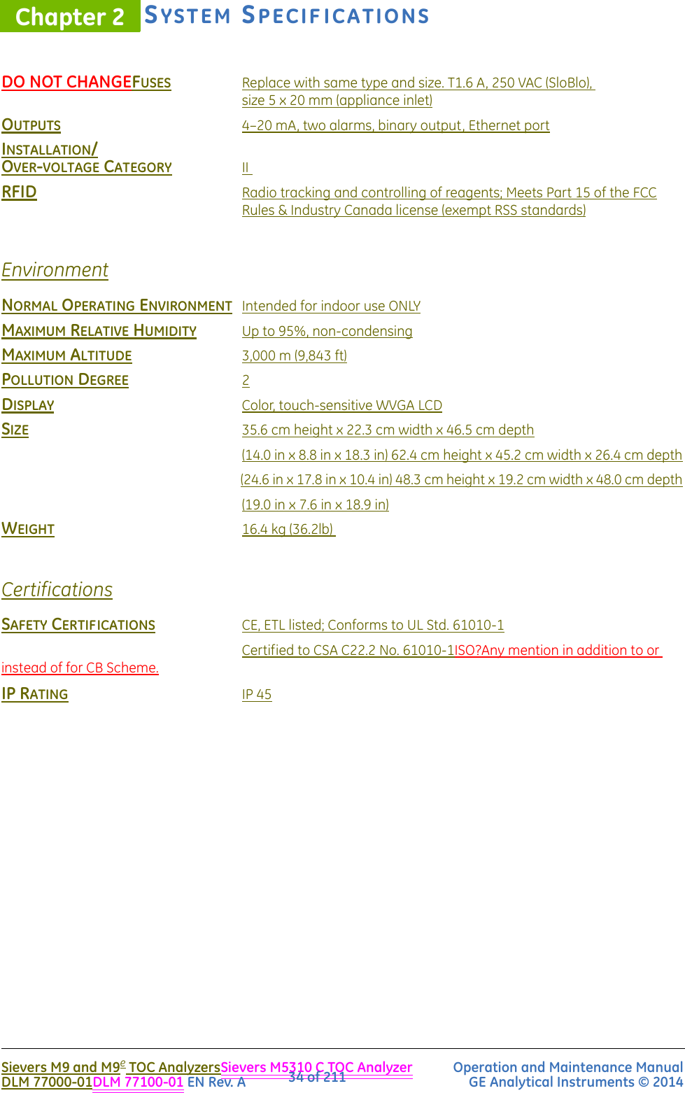

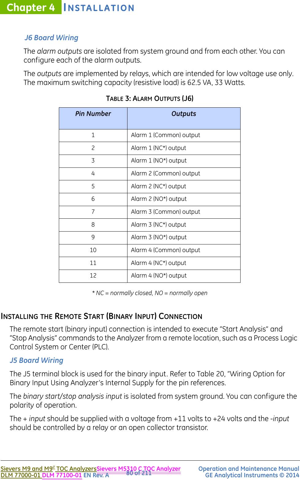
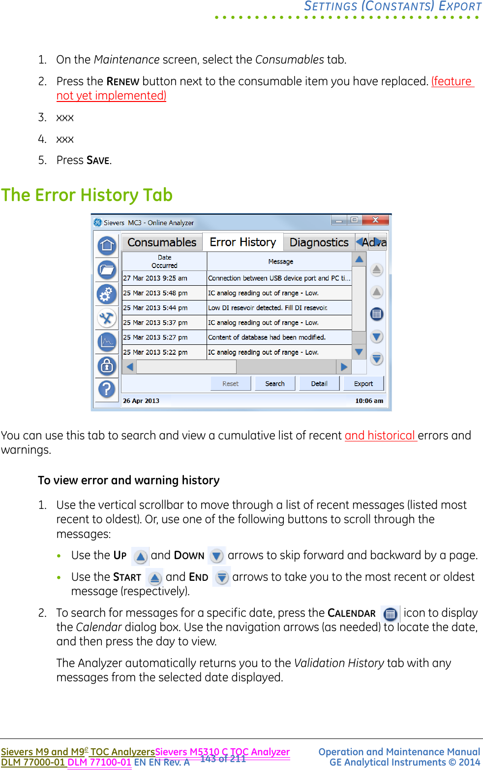
![SYSTEM OVERVIEWChapter 3Sievers M9 and M9eTOC AnalyzersSievers M5310 C TOC Analyzer Operation and Maintenance Manual DLM 77000-01DLM 77100-01 EN Rev. A GE Analytical Instruments © 201440 of 211sample flow path, connect the needle’s attached sample tubing to the sample inlet port located to the left of the iOS.As with the other models, you can set up the Portable TOC Analyzer for single grab samples to accommodate spot checks of TOC samples from various points in the water system. With this method, you will use a sipper tube2 and laboratory glassware (such as a flask or beaker).For step-by-step setup instructions, refer to “Sampling Using a Sipper Tube” on page 114.After sample is introduced into the Analyzer, 6M phosphoric acid (H3PO4) is injected into the sample3 at the programmed flow rate to reduce sample pH to 2. This allows for accurate measurement of TC and IC.An (optional) Inorganic Carbon Remover (ICR) may be used to remove excess IC by vacuum degasification. See “Inorganic Carbon Remover (ICR)” on page 45.See “Inorganic Carbon Remover (ICR)” on page 61 for more information on this optional configuration. If the ICR unit is utilized, additional acid may need to be added to the sample to remove excess IC by the ICR. The acidified sample is then combined4 with 15% ammonium persulfate [(NH4)2S2O8] to promote oxidation of the organics.5 The sample travels through a mixing coil and on to a stream splitter.The stream splitter divides the sample stream into two equal, but separate flows. One stream is processed for the measurement of IC. The other is processed for measurement of TC.The TC stream passes to an oxidation reactor where the sample is exposed to UV light. The combination of UV light and (depending on the application) persulfate oxidizes the organic compounds in the sample, converting carbon to CO2.The reactor is a spiral quartz tube wrapped around the UV lamp. The UV lamp emits light at 185 nm and 254 nm resulting in the formation of powerful chemical oxidizing agents in the form of hydroxyl radicals produced by the photolysis of water (equation 1) and persulfate (equations 2 and 3):H2O + hv (185 nm) →OH + H (1)S2O8-2 + hn (254 nm) →2 SO4-(2)SO4- + H2O →SO4- + OH (3)3. The phosphoric acid is referred to as Acid in the user interface.4. Depending on the application, some samples do NOT require the addition of persulfate. For example, when the TOC concentration in the sample is low (<1 ppm), complete oxidation can usually be achieved using only the hydroxyl radicals from the photolysis of water.5. The ammonium persulfate is referred to as Oxidizer in the user interface.](https://usermanual.wiki/GE-Analytical-Instruments/SIEVERSM9/User-Guide-2109564-Page-40.png)

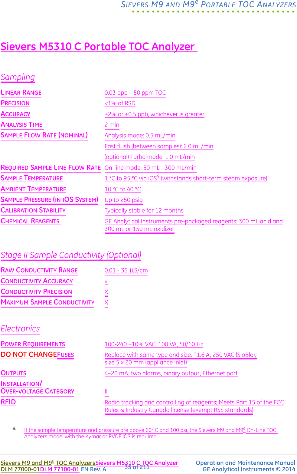
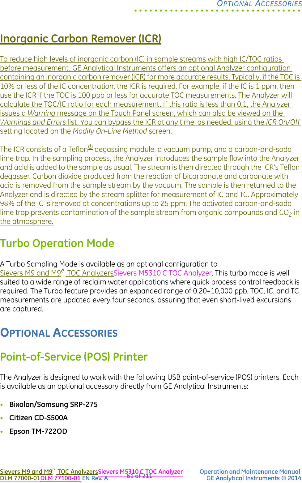
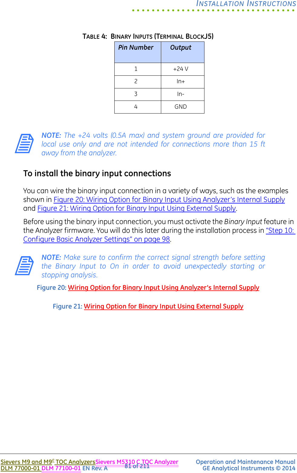
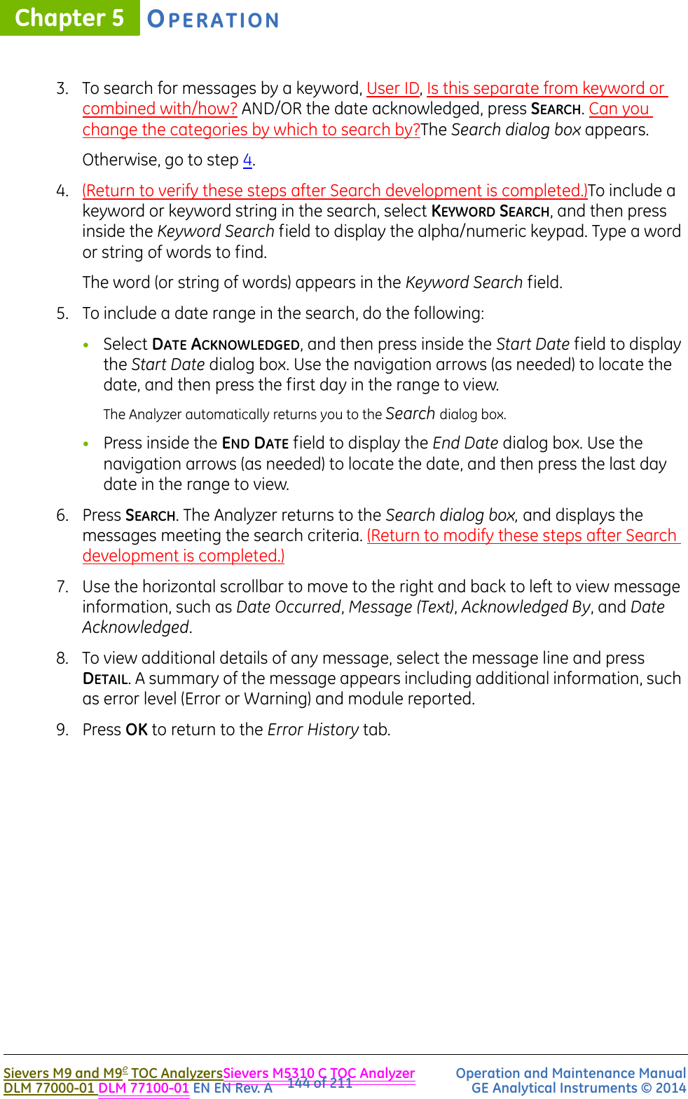
![SYSTEM OVERVIEWChapter 3Sievers M9 and M9eTOC AnalyzersSievers M5310 C TOC Analyzer Operation and Maintenance Manual DLM 77000-01DLM 77100-01 EN Rev. A GE Analytical Instruments © 201446 of 211dioxide produced from the reaction of bicarbonate and carbonate with acid is removed from the sample stream by the vacuum. The sample is then returned to the Analyzer and is directed by the stream splitter for measurement of IC and TC. Approximately 98% of the IC is removed at concentrations up to 25 ppm. Chemical Reagent SystemPhosphoric acid (H3PO4) and ammonium persulfate [(NH4)2S2O8], referred to respectively as Acid and Oxidizer in the User Interface and this manual, are introduced as reagents into the sample at different points in the flow path. The Acid brings about a chemical reaction to reduce the sample pH to 2, which is needed in order to allow for the accurate measurement of TC and IC.The acidified sample is then combined with the Oxidizer to create oxidation of the organics, to promote accurate TC and IC measurements. The sample then goes through a mixing coil and on to a stream splitter, where it is divided into two separate flows for TC and IC processing. Separate cartridge reservoirs hold the Acid and Oxidizer inside the Analyzer on the fluidics (right) side. Each reservoir is connected to a needle-and-syringe pump mechanism. The Analyzer activates each syringe pump at pre-programmed intervals and lengths (using the Auto Reagent setting) to dispense the optimal amount of Acid and Oxidizer into the sample.The modular assembly of the chemical reagent system is designed for easy removal and replacement of the reagent cartridges. See “Replacing Consumable Items” on page 164.Oxidizer ReactorPHOTO PlaceholderPHOTO Placeholder](https://usermanual.wiki/GE-Analytical-Instruments/SIEVERSM9/User-Guide-2109564-Page-46.png)

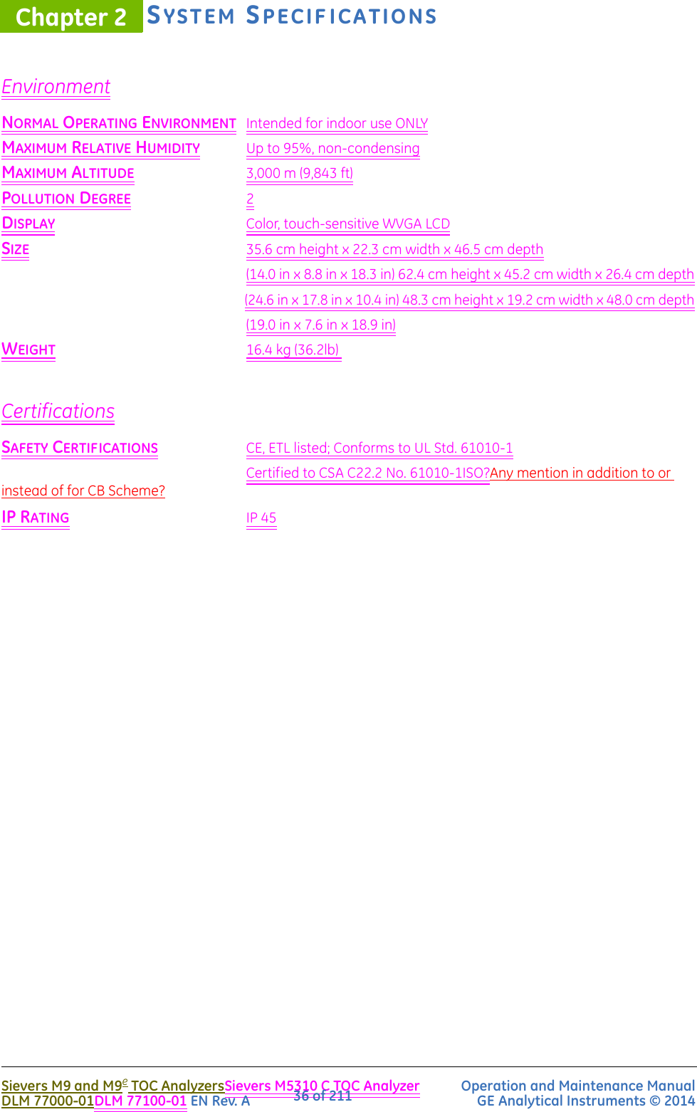
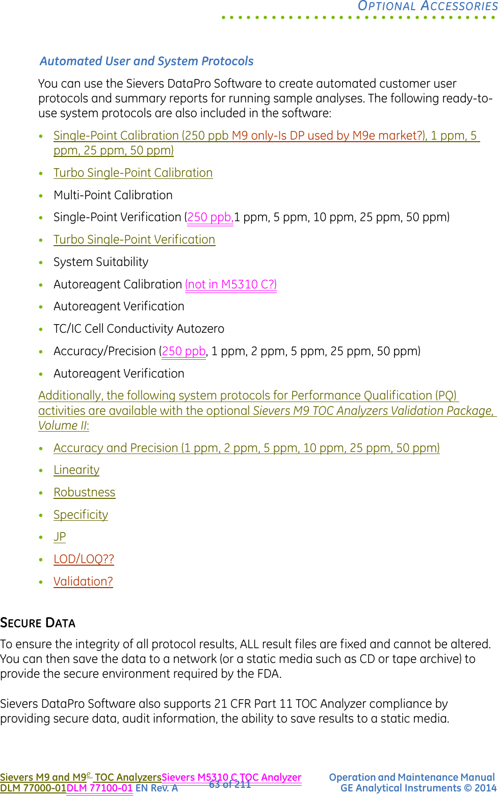
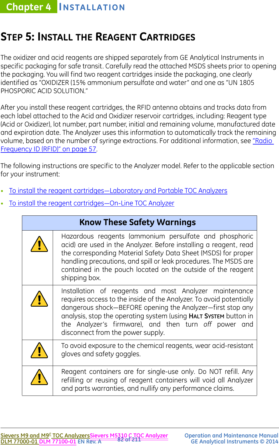
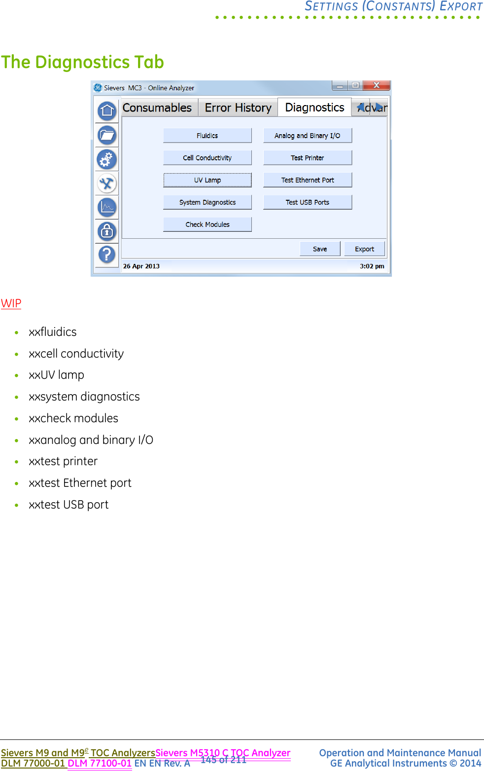
![SYSTEM OVERVIEWChapter 3Sievers M9 and M9eTOC AnalyzersSievers M5310 C TOC Analyzer Operation and Maintenance Manual DLM 77000-01DLM 77100-01 EN Rev. A GE Analytical Instruments © 201456 of 211The three 4-20 mA current loop analog outputs are independently isolated, so they may be connected to different remote locations [(such as multiple industrial control systems (ICS)] without causing inadvertent ground loops.SINGLE-CELL SIGNAL PROCESSOR BOARD(Laboratory and Portable TOC Analyzers Only)Figure 14: The Single-Cell Signal Processor BoardThe Single Cell Signal Processor (SCSP) Board is available as an optional configuration in Laboratory and Portable TOC Analyzers. This board measures the conductivity of the incoming water sample.](https://usermanual.wiki/GE-Analytical-Instruments/SIEVERSM9/User-Guide-2109564-Page-56.png)
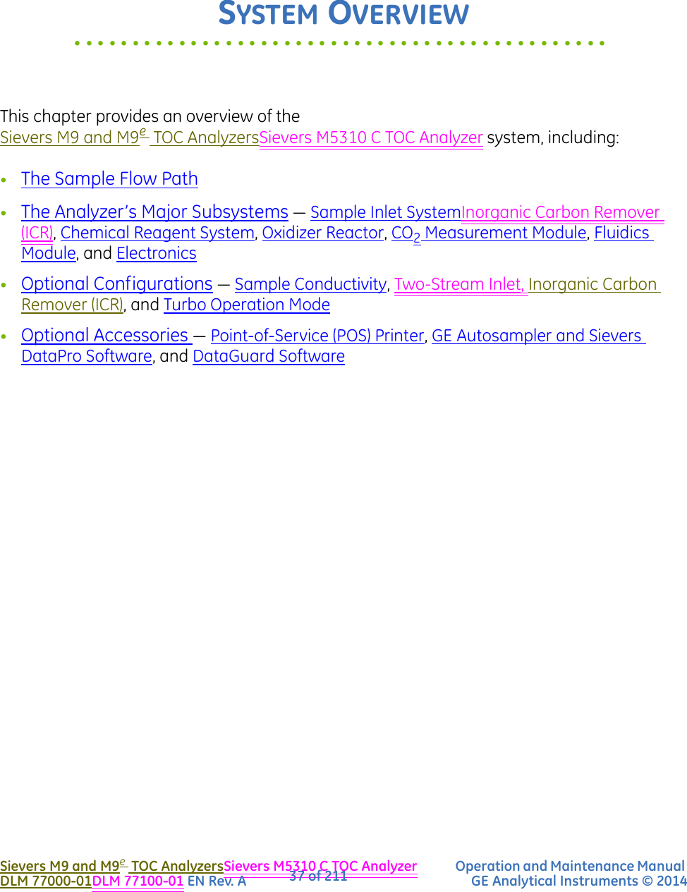
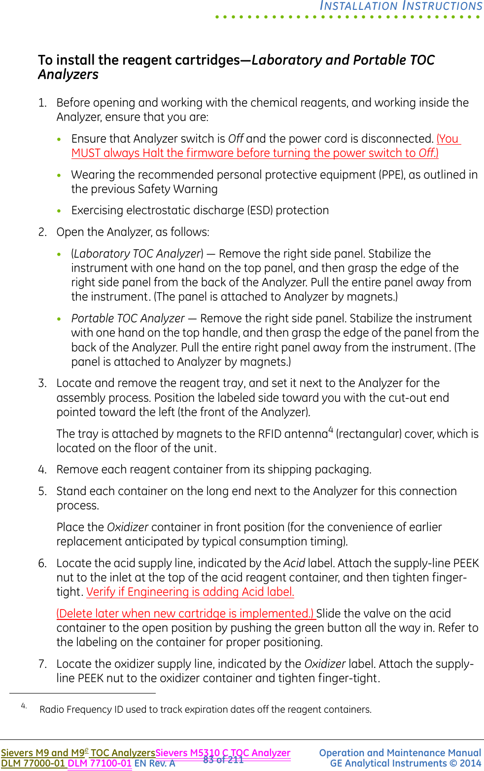
![SYSTEM OVERVIEWChapter 3Sievers M9 and M9eTOC AnalyzersSievers M5310 C TOC Analyzer Operation and Maintenance Manual DLM 77000-01DLM 77100-01 EN Rev. A GE Analytical Instruments © 201462 of 211GE Autosampler and Sievers DataPro Software(Laboratory and Portable TOC Analyzers Only)Any M9e electronics industry application?The GE Autosampler system can be used to automatically transfer up to 120 vial samples from the unit’s vial rack(s) into the sample inlet port on a Sievers MC9 and MC9e Laboratory or Portable TOC AnalyzerSievers M5310 C Laboratory or Portable TOC Analyzer. Sampling results are displayed and stored on your computer via the Sievers DataPro Software.This optional system for high-volume laboratory applications consists of the following:•GE Autosampler•Sievers DataPro Software, running on a your computer with a Windows® Operating Systems [Windows XP (SP2 or higher), Windows 7, Windows 8, Windows Server 2008, or Windows Server 2012]7/8 Vamsi is providing which systems are supported on both 32-bit and 64-bit systems.•Sievers MC9 and MC9e Laboratory or Portable TOC Analyzer or Sievers M5310 C Laboratory or Portable TOC Analyzer•Printer (optional)SIEVERS DATAPRO SOFTWARESievers DataPro Software integrates the GE Autosampler with Sievers M9 and M9eTOC Analyzersthe Sievers M5310 C TOC Analyzer, giving you the ability to operate the GE Autosampler with up to two Analyzers. The software runs on the following Microsoft operating systems with a familiar Windows interface design:•Windows XP (SP2 or higher)•Windows 7•Windows 8•Windows Server 2008•Windows Server 20127/8 Vamsi is providing which systems are supported on both 32-bit and 64-bit systems.](https://usermanual.wiki/GE-Analytical-Instruments/SIEVERSM9/User-Guide-2109564-Page-62.png)
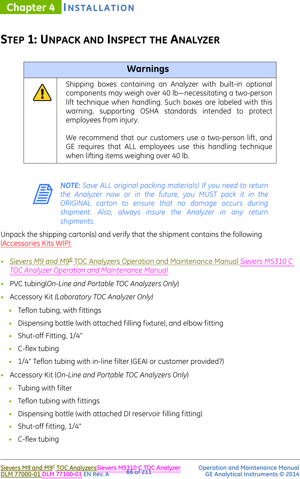
![.................................INSTALLATION INSTRUCTIONSSievers M9 and M9e TOC AnalyzersSievers M5310 C TOC Analyzer Operation and Maintenance ManualDLM 77000-01 DLM 77100-01 EN Rev. A GE Analytical Instruments © 201467 of 211•1/4” Teflon tubing with in-line filter (GEAI or customer provided?)•Waste outlet fitting•Certificate of Calibration•DataGuard Activation key (optional)•Reagents carton (shipped separately)Additional Equipment RequirementsYou will also need to provide the following for the installation process:•ESD protection•3/4” OD plastic tubing for the waste outlet (in kit or customer supplied??)•Ethernet cable (optional)(On-Line TOC Analyzer Only)•Conduit connector (strain relief hubs) for power conduit wiring•Sealing washer for conduit connector•Ring terminal for AC conduit ground wire, 16-14 American Wire Gauge (AWG)•Insulated wire for AC power conduit1 (18-12 AWG), rated to 300 Volts. Strip length should be 8-9 mm (.33 in.) (Metallic conduit is required for the Analyzer to meet CE Mark electrical requirements.)•External circuit breaker or switch that disconnects both poles of the supply voltage, rated appropriately•Strain relief hub (conduit connector) and washer for I/O wiring•Analog (4-20 mA) recorder (optional)•Wire for 4-20 mA and alarm output (28-16 AWG), rated to 300 Volts(On-Line TOC Analyzer Only)•Mounting hardware to support the Analyzer — Mounting bolts should support four times the weight of the Analyzer [Total of 64.20 kg (141.50 lb)]. For more information, see “Step 3: Select a Location for the Analyzer.”(Portable TOC Analyzer Only) •Analog (4-20 mA) recorder (optional)1. Metallic conduit is required for the Analyzer to meet CE Mark electrical requirements.](https://usermanual.wiki/GE-Analytical-Instruments/SIEVERSM9/User-Guide-2109564-Page-67.png)
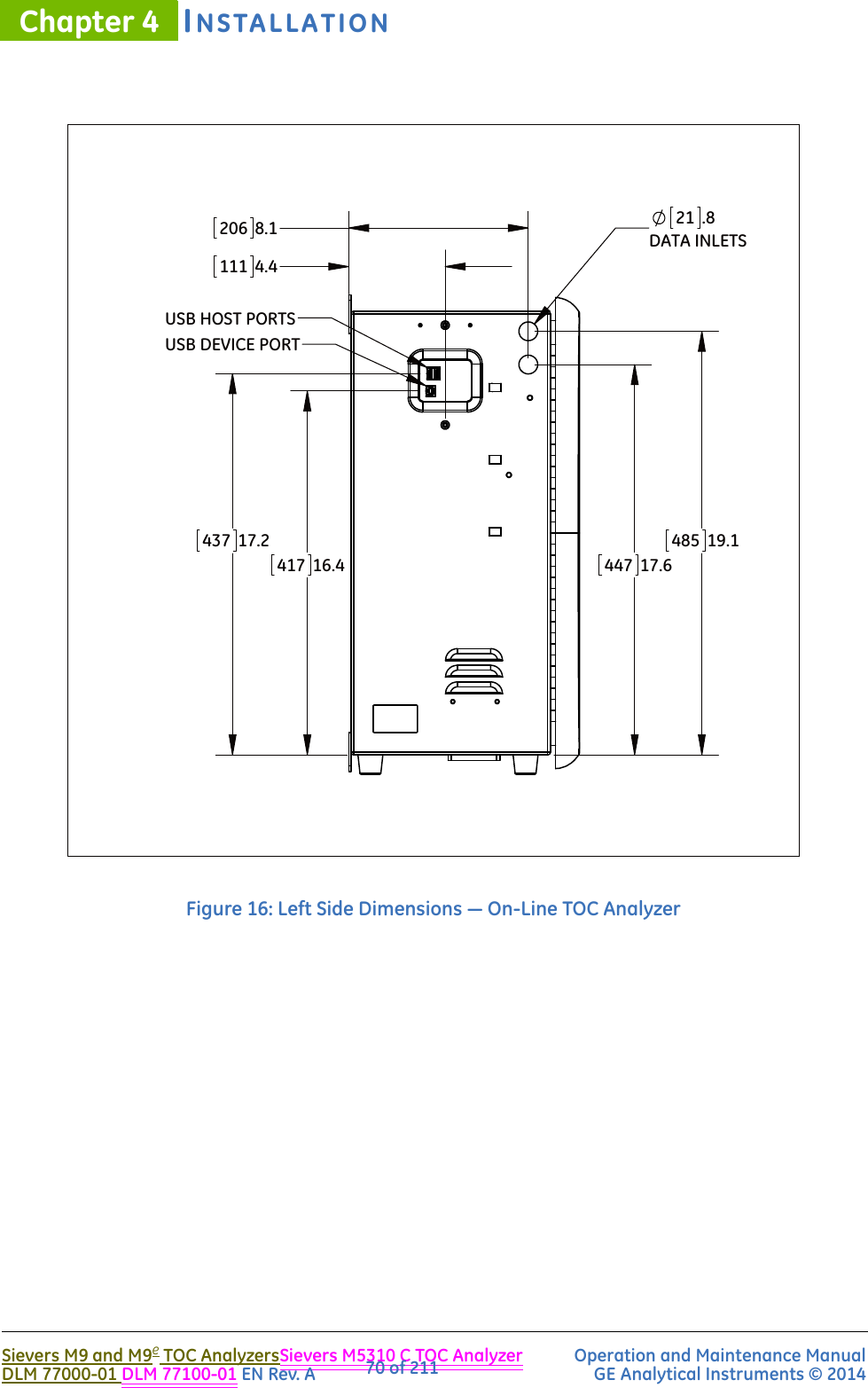
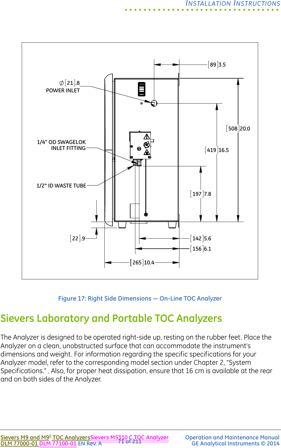
![INSTALLATIONChapter 4Sievers M9 and M9e TOC AnalyzersSievers M5310 C TOC Analyzer Operation and Maintenance ManualDLM 77000-01 DLM 77100-01 EN Rev. A GE Analytical Instruments © 201468 of 211STEP 2: COMPLETE THE IDENTIFICATION RECORDSComplete the Identification Records information on page 4 by recording the Analyzer serial number and the date of installation. The serial number is located on the rear outside panel of Laboratory and Portable TOC Analyzers, and on the left outside panel of the On-Line TOC Analyzer.STEP 3: SELECT A LOCATION FOR THE ANALYZERThe enclosure for the On-Line TOC Analyzer is rated IP 45 to withstand the hazards of industrial process environments. The Portable TOC Analyzer is rated (a WIP) IP 21 for incidental exposure to water.Select a location away from direct sunlight and extreme temperatures. Avoid operating at elevated temperatures greater than 40 °C, which can prevent proper operation. Also avoid operating at temperatures lower than 10 °C, which can cause errors in the measurements. Make sure that the back of the Analyzer is protected from water spray to ensure the electrical and data connections remain dry.In addition to these general instructions, refer to the sections that follow for information pertaining to the specific model of your Analyzer.Sievers On-Line TOC AnalyzerSievers M9 or M9e On-Line TOC Analyzers are designed to be mounted on a wall or support stand. When selecting the location, mount the Analyzer so that the display screen is approximately at eye-level. For illustrations of required clearances, see Figures 15, 16, and 17. Allow a minimum of 5 cm clearance between the back of the Analyzer and the wall for heat dissipation. Plan for 30.5 cm of clearance on the sides, top, and bottom of the Analyzer for the plumbing and electrical connections. This clearance provides for the proper circulation for temperature and humidity control. You will need to provide hardware for mounting the Analyzer on a wall or instrument rack, as hardware should be selected based on site-specific circumstances. Choose mounting bolts to support four times the weight of the unit2 [total = 65.68 kg (144.80 lb)].2. 4 x 26.42 kg = 65.68 kg (4 x 35.2 lb = 144.80 lb)](https://usermanual.wiki/GE-Analytical-Instruments/SIEVERSM9/User-Guide-2109564-Page-68.png)
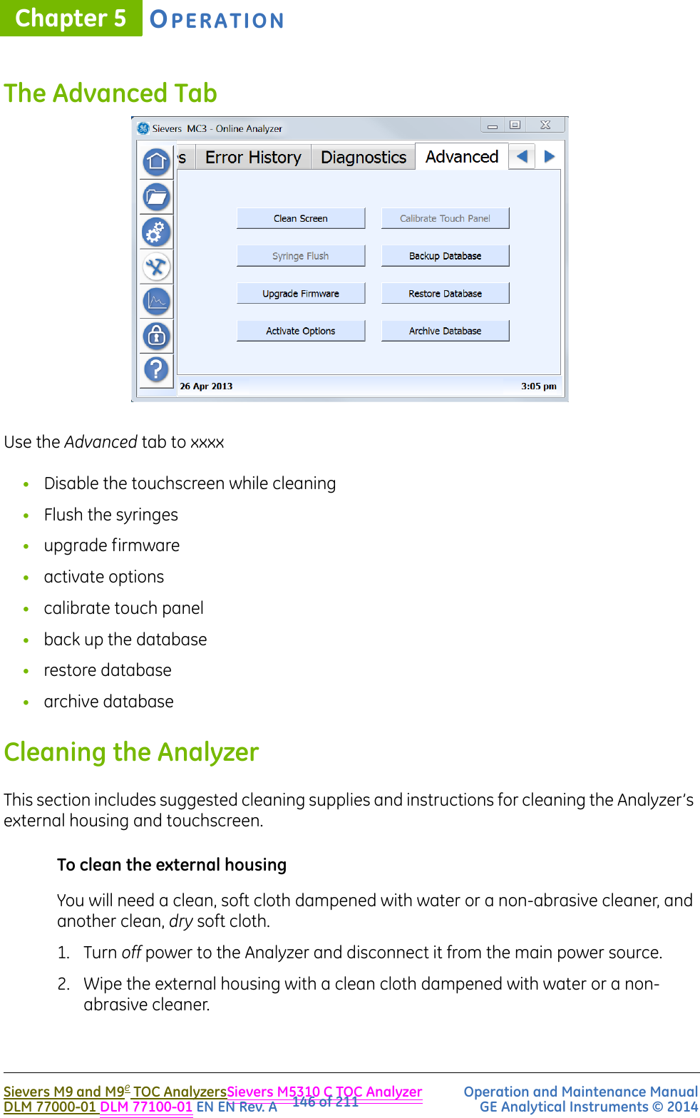
![.................................INSTALLATION INSTRUCTIONSSievers M9 and M9e TOC AnalyzersSievers M5310 C TOC Analyzer Operation and Maintenance ManualDLM 77000-01 DLM 77100-01 EN Rev. A GE Analytical Instruments © 201469 of 211Figure 15: Required Installation Clearances — On-Line TOC Analyzer45017.7032712.952720.854621.54X 8.3 [305]12.0 [305]12.0 [305]12.0 [305]12.0 [450]17.7IN FRONT[50]2.0IN BACK](https://usermanual.wiki/GE-Analytical-Instruments/SIEVERSM9/User-Guide-2109564-Page-69.png)
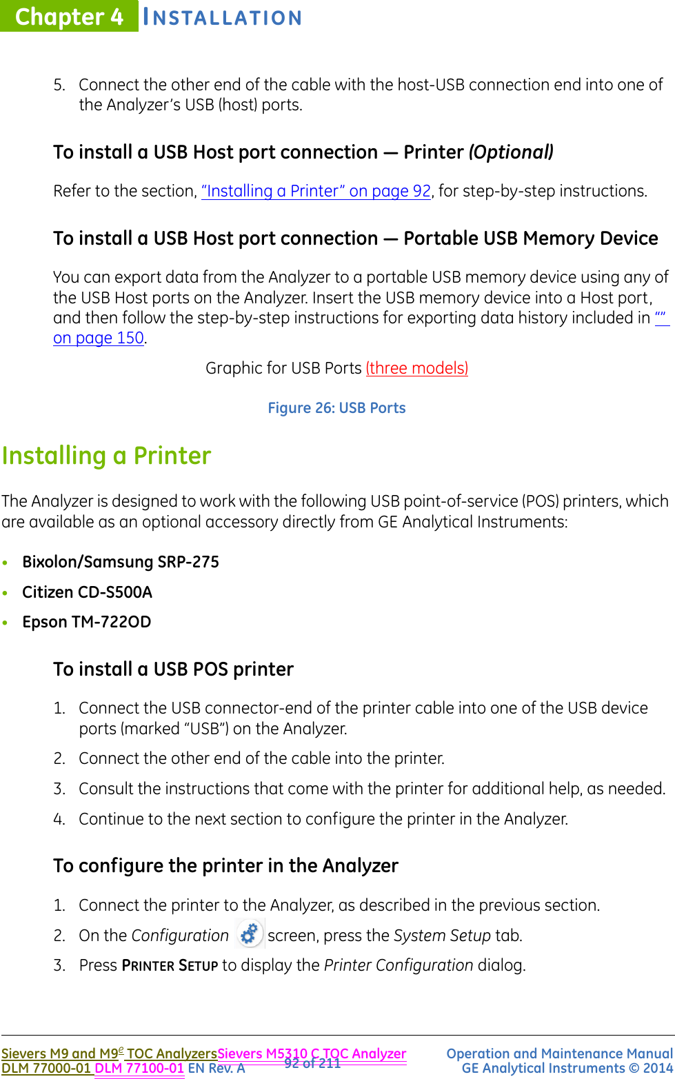
![.................................INSTALLATION INSTRUCTIONSSievers M9 and M9e TOC AnalyzersSievers M5310 C TOC Analyzer Operation and Maintenance ManualDLM 77000-01 DLM 77100-01 EN Rev. A GE Analytical Instruments © 201491 of 211To install a USB connection — Device Port (Optional) 1. Install the DataPro Software on your computer now, or come back to and perform this instruction after you have installed the software. Instructions for installing the DataPro Software are included in the GE Autosampler Installation Guide.2. Locate one of the USB-Device to USB-Host cables in the GE Autosampler Accessories Kit. [You will use the other cable later in this section.)3. Connect the Device USB-Device connection end of the cable into the “Computer” USB port on the Analyzer.4. Connect the other end of the cable with the host USB connection end into your computer’s USB (host) port.5. “To install a USB Host port connection — GE Autosampler (Optional)” on page 91.]USB HOST PORTSThe On-Line and Portable TOC Analyzers have two USB host ports (labeled “USB”) on the back of the instrument. The (Laboratory TOC Analyzer) also contains two USB host ports (labeled “USB”) on the back of the instrument, as well one additional USB host port (labeled “USB”) on the front of the instrument. The USB host ports are designed for use with the following peripheral accessories:•GE Autosampler•Printer (Must be one of the specific brands/models identified in the “Installing a Printer” section.)•Portable USB memory deviceTo install a USB Host port connection — GE Autosampler (Optional) 1. Complete this instruction after you have installed the DataPro Software on your computer, or come back to and perform this instruction after you have installed the software.2. Ensure that you have connected the Analyzer to your computer, as described in “To install a USB connection — Device Port (Optional)” on page 90. 3. Locate the remaining USB-Device to USB-Host cable in the GE Autosampler Accessories Kit.4. Connect the Device-USB connection end of the cable into the “Computer” USB port on the GE Autosampler.](https://usermanual.wiki/GE-Analytical-Instruments/SIEVERSM9/User-Guide-2109564-Page-91.png)


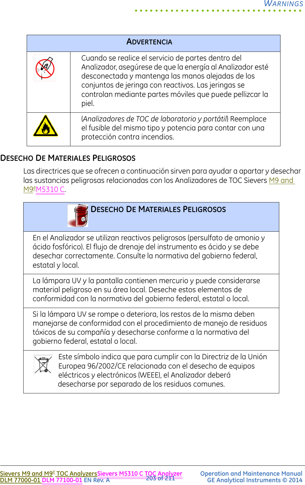
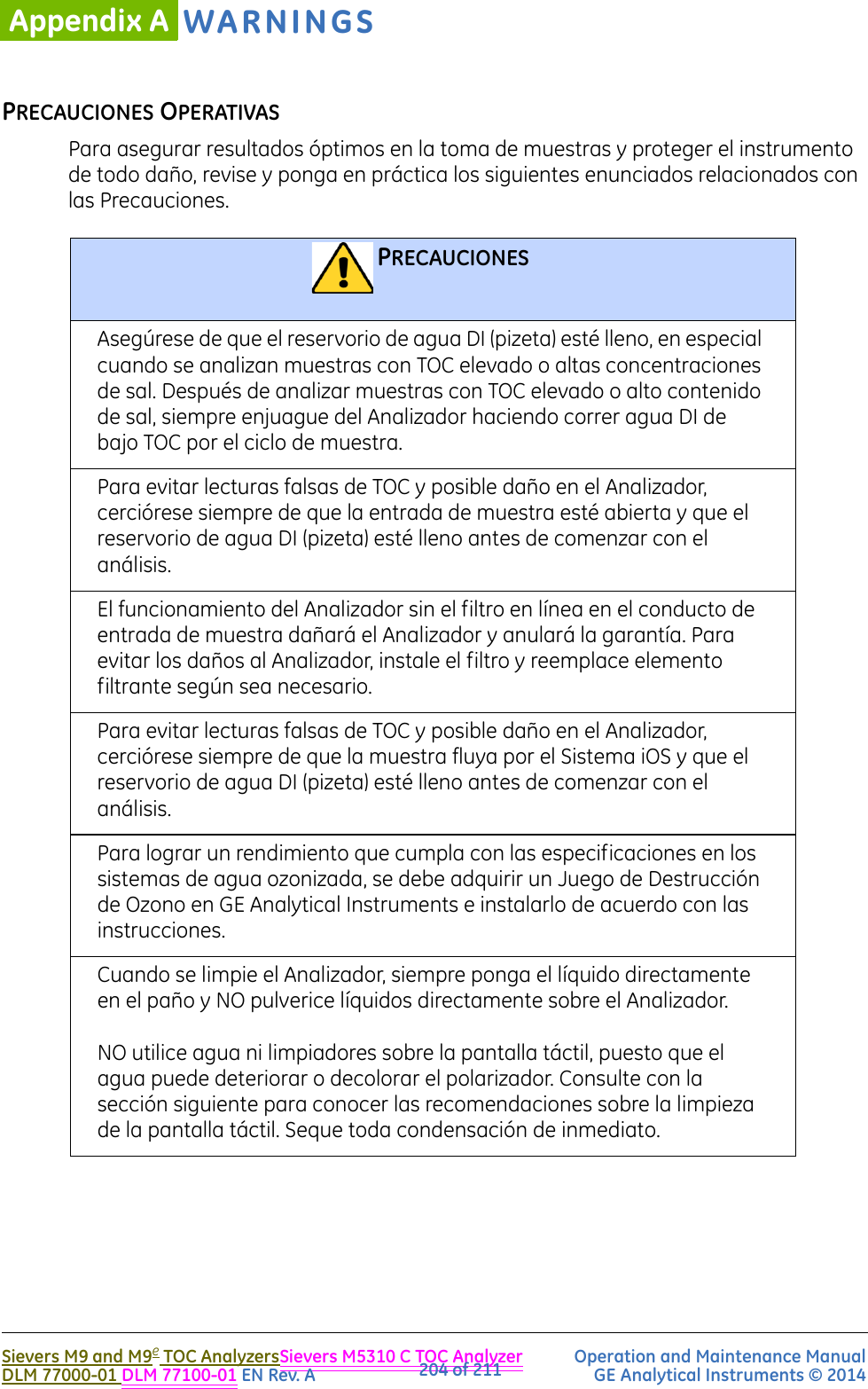
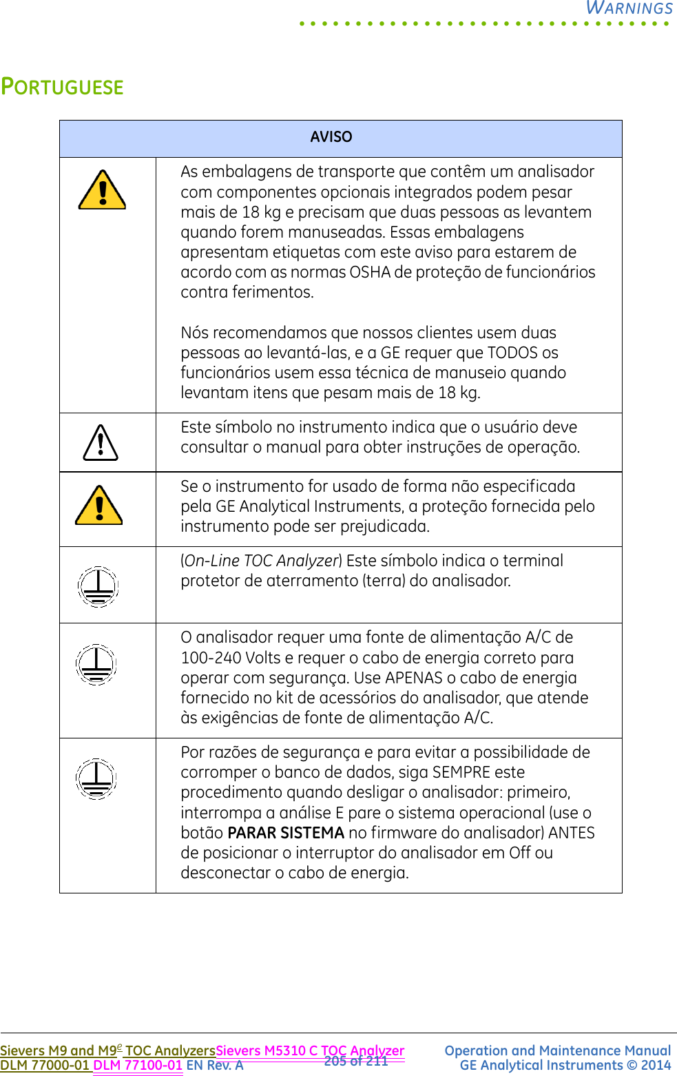
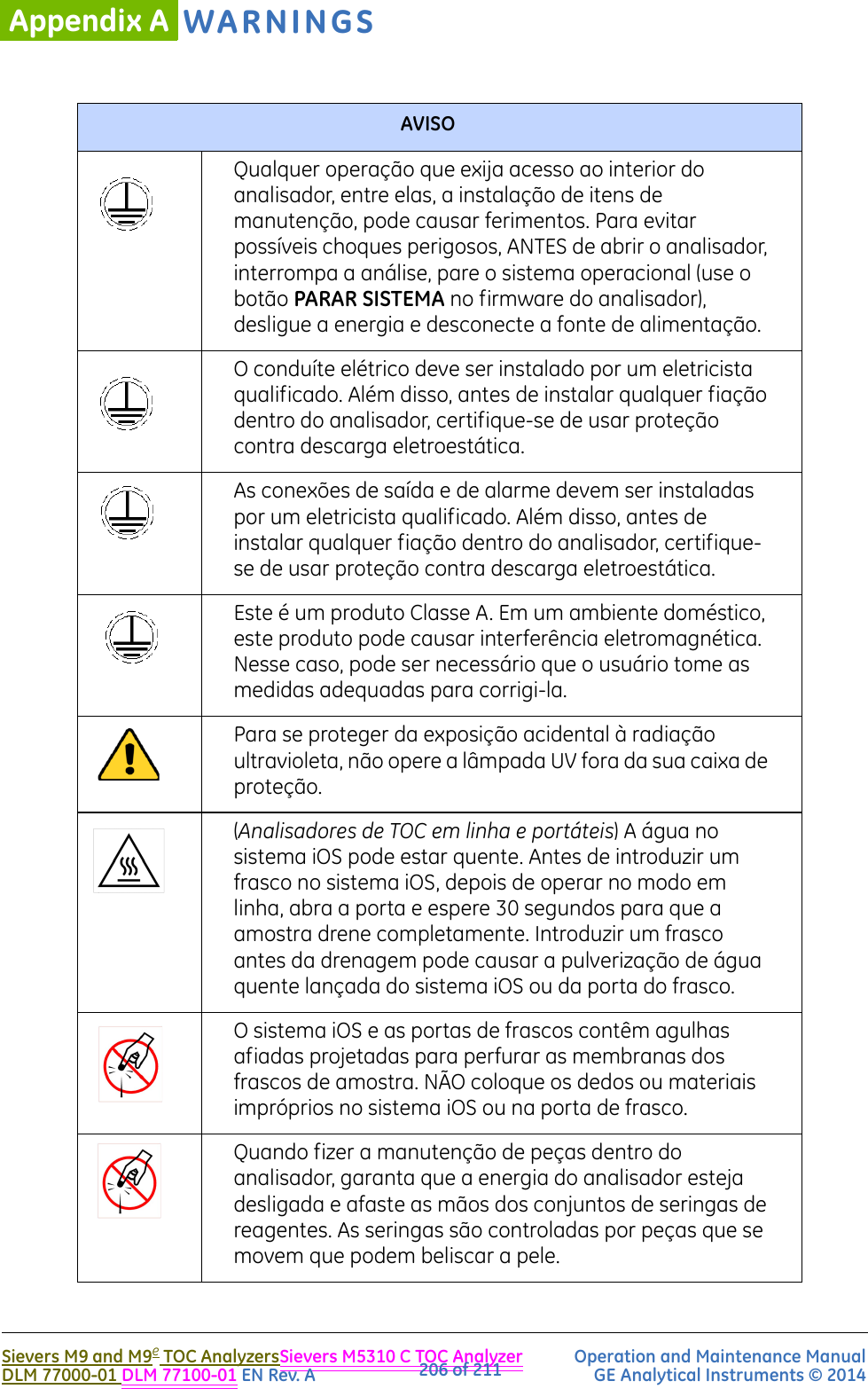
![.................................WARNINGSSievers M9 and M9e TOC AnalyzersSievers M5310 C TOC Analyzer Operation and Maintenance ManualDLM 77000-01 DLM 77100-01 EN Rev. A GE Analytical Instruments © 2014201 of 211EspañolADVERTENCIALas cajas de envío que contienen el Analizador con los componentes opcionales incorporados pueden pesar más de 18 kg (40 lb). Se necesita a dos personas para levantarlas cuando se las manipule. Las cajas presentan una etiqueta con esta advertencia, conforme a las normas OSHA destinadas a la protección del empleado contra lesiones.Recomendamos a nuestros clientes emplear la ayuda de dos personas y GE requiere que TODOS los empleados utilicen la técnica de manejo de materiales cuando se deban levantar elementos que superen los 18 kg (40 lb). Este símbolo en el instrumento indica que el usuario debe consultar el manual para conocer las instrucciones de funcionamiento.Si este instrumento se utiliza de una manera que no sea la especificada por GE Analytical Instruments, es posible que se vea disminuida la protección provista por el instrumento.(Analizador de TOC En Línea) Este símbolo indica el terminal de protección a tierra (masa) para el Analizador.El Analizador requiere una alimentación por red de CA de 100 a 240 voltios, y necesita el cable de energía correcto para un funcionamiento seguro del instrumento. Utilice SOLAMENTE el cable de energía suministrado en el Juego de Accesorios del Analizador junto con el Analizador, que cumple con estos requisitos de alimentación por red de CA.Por razones de seguridad y para evitar la posibilidad de corromper la base de datos, SIEMPRE siga este procedimiento cuando corte el Analizador. Primero pare el análisis Y detenga el sistema operativo (utilizando el botón Detener Sistema [Halt System] en el Firmware del Analizador) ANTES de pulsar el interruptor de energía del analizador en la posición Off o desenchufar el cable de energía.](https://usermanual.wiki/GE-Analytical-Instruments/SIEVERSM9/User-Guide-2109564-Page-201.png)
![WARNINGSAppendix ASievers M9 and M9e TOC AnalyzersSievers M5310 C TOC Analyzer Operation and Maintenance ManualDLM 77000-01 DLM 77100-01 EN Rev. A GE Analytical Instruments © 2014202 of 211Toda operación que necesite el acceso al interior del Analizador, incluyéndose la instalación de los elementos de mantenimiento, podría provocar lesiones. Para evitar el peligro de una posible descarga eléctrica, ANTES de abrir el Analizador, primero pare el análisis, detenga el sistema operativo (utilizando el botón Detener Sistema [HALT SYSTEM] en el Firmware del Analizador), y luego apague la energía y desconecte de la alimentación por red.Un electricista matriculado debe instalar un conductor eléctrico de tipo "conduit". Además, antes de instalar cualquier cableado dentro del Analizador, asegúrese de usar protección electrostática.La instalación de las conexiones para las salidas y alarmas debe ser instalada por un electricista matriculado. Además, antes de instalar cualquier cableado dentro del Analizador, asegúrese de usar protección electrostática.Este es un producto de Clase A. En un entorno doméstico, este producto puede causar interferencia electromagnética, en cuyo caso el usuario tal vez deba tomar medidas adecuadas para corregir dicha interferencia.Para proteger contra la exposición accidental a la radiación de rayos ultravioletas, no ponga a funcionar la lámpara UV fuera de su carcasa de protección.(Analizadores de TOC En Línea y Portátil) El agua en el Sistema iOS puede estar caliente. Antes de introducir un vial en el Sistema iOS después de hacer funcionar el instrumento en modo en línea, deslice la puerta para abrirla y espere 30 segundos para que la muestra drene totalmente. Cuando se introduce un vial antes de drenar puede que el agua caliente se expulse y salpique hacia arriba del Sistema iOS o el puerto de viales.El Sistema iOS y los puertos de viales contienen dos agujas filosas diseñadas para perforar los septa de los viales con las muestras. NO ponga los dedos o materiales inadecuados dentro del Sistema iOS o el puerto de viales.ADVERTENCIA](https://usermanual.wiki/GE-Analytical-Instruments/SIEVERSM9/User-Guide-2109564-Page-202.png)