GE Analytical Instruments SIEVERSM9 Total Organic Carbon Analyzer User Manual DLM 77000 01 EN MC9 MC2
GE Analytical Instruments, Inc. Total Organic Carbon Analyzer DLM 77000 01 EN MC9 MC2
User Manual


Printed in USA ©2014
The Americas Europe/Middle East/Africa Asia Pacific
6060 Spine Road Unit 3, Mercury Way 7/F, Building 1, No. 1 Hua Tuo Rd.
Boulder, CO 80301-3687 USA Urmston, Manchester, M41 7LY ZhangJiang Hi-Tech Park, Pudong
T +1 800 255 6964 United Kingdom Shanghai China 201203
T +1 303 444 2009 T +44 0 161 864 6800 T + 8621 38777735
F +1 303 444 9543 F +44 0 161 864 6829 F + 8621 38777469
www.geinstruments.com geai.europe@ge.com geai.asia@ge.com
techsupport@geinstruments.com

Sievers M9 and M9e TOC AnalyzersSievers M5310 C TOC Analyzer Operation and Maintenance Manual
DLM 77000-01DLM 77100-01 EN Rev. A GE Analytical Instruments © 2014
3 of 211
Identification Records
Analyzer serial number1: _________________________
Analyzer serial number1: _________________________
Date Analyzer Received and Installed2: _________________________
1. The serial number is located on the rear panel of the Laboratory and Portable Analyzers, and on the side panel
of the On-Line TOC Analyzer.
2. This is the warranty date.

Sievers M9 and M9e TOC AnalyzersSievers M5310 C TOC Analyzer Operation and Maintenance Manual
DLM 77000-01DLM 77100-01 EN Rev. A GE Analytical Instruments © 2014
4 of 211
Table of Contents
Identification Records . . . . . . . . . . . . . . . . . . . . . . . . . . . . . . . . . . . . . . . . . . . . . . . . 3
Sievers M9 and M9e TOC Analyzers. . . . . . . . . . . . . . . . . . . . . . . . . . . . . . . . . . . . 16
Sievers M5310 C TOC Analyzer. . . . . . . . . . . . . . . . . . . . . . . . . . . . . . . . . . . . . . . . 16
Document Revision History. . . . . . . . . . . . . . . . . . . . . . . . . . . . . . . . . . . . . . . . . . . . . . . . . . . . . . . . . . 16
Trademarks and Patents . . . . . . . . . . . . . . . . . . . . . . . . . . . . . . . . . . . . . . . . . . . . . . . . . . . . . . . . . . . . 16
Confidentiality . . . . . . . . . . . . . . . . . . . . . . . . . . . . . . . . . . . . . . . . . . . . . . . . . . . . . . . . . . . . . . . . . . . . . . 17
Declaration of Conformity . . . . . . . . . . . . . . . . . . . . . . . . . . . . . . . . . . . . . . . . . . . . . . . . . . . . . . . . . . . 17
Standard Limited Warranty . . . . . . . . . . . . . . . . . . . . . . . . . . . . . . . . . . . . . . . . . . . . . . . . . . . . . . . . . 17
Chapter 1: Introduction . . . . . . . . . . . . . . . . . . . . . . . . . . . . . . . . . . . . . . . . . . . . . . 23
Chapter 2: System Specifications . . . . . . . . . . . . . . . . . . . . . . . . . . . . . . . . . . . . . 25
Sievers M9 and M9e On-Line TOC Analyzers. . . . . . . . . . . . . . . . . . . . . . . . . . . . . . . . . . . . . . . . . . . . . . 25
Sievers M5310 C On-Line TOC Analyzer . . . . . . . . . . . . . . . . . . . . . . . . . . . . . . . . . . . . . . . . . . . . . . . . . . 27
Sievers MC9 and MC9e Laboratory TOC Analyzers. . . . . . . . . . . . . . . . . . . . . . . . . . . . . . . . . . . . . . . . 29
Sievers M5310 C Laboratory TOC Analyzer. . . . . . . . . . . . . . . . . . . . . . . . . . . . . . . . . . . . . . . . . . . . . . . 31
Sievers M9 and M9e Portable TOC Analyzers . . . . . . . . . . . . . . . . . . . . . . . . . . . . . . . . . . . . . . . . . . . . . 33
Chapter 3: System Overview. . . . . . . . . . . . . . . . . . . . . . . . . . . . . . . . . . . . . . . . . . 37
The Sample Flow Path . . . . . . . . . . . . . . . . . . . . . . . . . . . . . . . . . . . . . . . . . . . . . . . . . . . . . . . . . . . . . . 38
CO2 Transfer Modules . . . . . . . . . . . . . . . . . . . . . . . . . . . . . . . . . . . . . . . . . . . . . . . . . . . . . . . . . . . . . . . . . . 41
The Analyzer’s Major Subsystems. . . . . . . . . . . . . . . . . . . . . . . . . . . . . . . . . . . . . . . . . . . . . . . . . . . . 42
Sample Inlet System . . . . . . . . . . . . . . . . . . . . . . . . . . . . . . . . . . . . . . . . . . . . . . . . . . . . . . . . . . . . . . . . . . . . 43
The iOS System . . . . . . . . . . . . . . . . . . . . . . . . . . . . . . . . . . . . . . . . . . . . . . . . . . . . . . . . . . . . . . . . . . . . . 44
Inorganic Carbon Remover (ICR). . . . . . . . . . . . . . . . . . . . . . . . . . . . . . . . . . . . . . . . . . . . . . . . . . . . . . . . . 45
Chemical Reagent System . . . . . . . . . . . . . . . . . . . . . . . . . . . . . . . . . . . . . . . . . . . . . . . . . . . . . . . . . . . . . . 46
Oxidizer Reactor. . . . . . . . . . . . . . . . . . . . . . . . . . . . . . . . . . . . . . . . . . . . . . . . . . . . . . . . . . . . . . . . . . . . . . . . 46
CO2 Measurement Module . . . . . . . . . . . . . . . . . . . . . . . . . . . . . . . . . . . . . . . . . . . . . . . . . . . . . . . . . . . . . . 47
Fluidics Module. . . . . . . . . . . . . . . . . . . . . . . . . . . . . . . . . . . . . . . . . . . . . . . . . . . . . . . . . . . . . . . . . . . . . . . . . 48
Electronics . . . . . . . . . . . . . . . . . . . . . . . . . . . . . . . . . . . . . . . . . . . . . . . . . . . . . . . . . . . . . . . . . . . . . . . . . . . . . 49

Sievers M9 and M9e TOC AnalyzersSievers M5310 C TOC Analyzer Operation and Maintenance Manual
DLM 77000-01DLM 77100-01 EN Rev. A GE Analytical Instruments © 2014
5 of 211
Electronic Controller and Processing Boards . . . . . . . . . . . . . . . . . . . . . . . . . . . . . . . . . . . . . . . . . 49
Data/User Controller (DUC) Board . . . . . . . . . . . . . . . . . . . . . . . . . . . . . . . . . . . . . . . . . . . . . . . . . . . 50
Instrument Controller Board . . . . . . . . . . . . . . . . . . . . . . . . . . . . . . . . . . . . . . . . . . . . . . . . . . . . . . . . 51
Fluidics Controller Board . . . . . . . . . . . . . . . . . . . . . . . . . . . . . . . . . . . . . . . . . . . . . . . . . . . . . . . . . . . . 53
Dual Cell Signal Processor (DCSP) Board . . . . . . . . . . . . . . . . . . . . . . . . . . . . . . . . . . . . . . . . . . . . . 54
I/O Controller Board . . . . . . . . . . . . . . . . . . . . . . . . . . . . . . . . . . . . . . . . . . . . . . . . . . . . . . . . . . . . . . . . 55
Single-Cell Signal Processor Board . . . . . . . . . . . . . . . . . . . . . . . . . . . . . . . . . . . . . . . . . . . . . . . . . . 56
Touch Panel Display . . . . . . . . . . . . . . . . . . . . . . . . . . . . . . . . . . . . . . . . . . . . . . . . . . . . . . . . . . . . . . . . . . . . 57
Radio Frequency ID (RFID). . . . . . . . . . . . . . . . . . . . . . . . . . . . . . . . . . . . . . . . . . . . . . . . . . . . . . . . . . . . . . . 57
Optional Configurations . . . . . . . . . . . . . . . . . . . . . . . . . . . . . . . . . . . . . . . . . . . . . . . . . . . . . . . . . . . . . 59
Sample Conductivity. . . . . . . . . . . . . . . . . . . . . . . . . . . . . . . . . . . . . . . . . . . . . . . . . . . . . . . . . . . . . . . . . . . . 60
Two-Stream Inlet . . . . . . . . . . . . . . . . . . . . . . . . . . . . . . . . . . . . . . . . . . . . . . . . . . . . . . . . . . . . . . . . . . . . . . . 60
Inorganic Carbon Remover (ICR). . . . . . . . . . . . . . . . . . . . . . . . . . . . . . . . . . . . . . . . . . . . . . . . . . . . . . . . . 61
Turbo Operation Mode. . . . . . . . . . . . . . . . . . . . . . . . . . . . . . . . . . . . . . . . . . . . . . . . . . . . . . . . . . . . . . . . . . 61
Optional Accessories. . . . . . . . . . . . . . . . . . . . . . . . . . . . . . . . . . . . . . . . . . . . . . . . . . . . . . . . . . . . . . . . 61
Point-of-Service (POS) Printer . . . . . . . . . . . . . . . . . . . . . . . . . . . . . . . . . . . . . . . . . . . . . . . . . . . . . . . . . . . 61
GE Autosampler and Sievers DataPro Software . . . . . . . . . . . . . . . . . . . . . . . . . . . . . . . . . . . . . . . . . . 62
Sievers DataPro Software . . . . . . . . . . . . . . . . . . . . . . . . . . . . . . . . . . . . . . . . . . . . . . . . . . . . . . . . . . . 62
Secure Data . . . . . . . . . . . . . . . . . . . . . . . . . . . . . . . . . . . . . . . . . . . . . . . . . . . . . . . . . . . . . . . . . . . . . . . . 63
DataGuard Software . . . . . . . . . . . . . . . . . . . . . . . . . . . . . . . . . . . . . . . . . . . . . . . . . . . . . . . . . . . . . . . . . . . 64
Chapter 4: Installation . . . . . . . . . . . . . . . . . . . . . . . . . . . . . . . . . . . . . . . . . . . . . . . 65
Overview . . . . . . . . . . . . . . . . . . . . . . . . . . . . . . . . . . . . . . . . . . . . . . . . . . . . . . . . . . . . . . . . . . . . . . . . . . . 65
Installation Instructions . . . . . . . . . . . . . . . . . . . . . . . . . . . . . . . . . . . . . . . . . . . . . . . . . . . . . . . . . . . . . 65
Step 1: Unpack and Inspect the Analyzer . . . . . . . . . . . . . . . . . . . . . . . . . . . . . . . . . . . . . . . . . . . . 66
Additional Equipment Requirements . . . . . . . . . . . . . . . . . . . . . . . . . . . . . . . . . . . . . . . . . . . . . . . . . . . . 67
Step 2: Complete the Identification Records . . . . . . . . . . . . . . . . . . . . . . . . . . . . . . . . . . . . . . . . . 68
Step 3: Select a Location for the Analyzer . . . . . . . . . . . . . . . . . . . . . . . . . . . . . . . . . . . . . . . . . . . . 68
Sievers On-Line TOC Analyzer . . . . . . . . . . . . . . . . . . . . . . . . . . . . . . . . . . . . . . . . . . . . . . . . . . . . . . . . . . . 68
Sievers Laboratory and Portable TOC Analyzers. . . . . . . . . . . . . . . . . . . . . . . . . . . . . . . . . . . . . . . . . . 71
On-Line Sampling . . . . . . . . . . . . . . . . . . . . . . . . . . . . . . . . . . . . . . . . . . . . . . . . . . . . . . . . . . . . . . . . . . 72
GE Autosampler System . . . . . . . . . . . . . . . . . . . . . . . . . . . . . . . . . . . . . . . . . . . . . . . . . . . . . . . . . . . . 72
Step 4: Install Power and I/O Control Wiring . . . . . . . . . . . . . . . . . . . . . . . . . . . . . . . . . . . . . . . . . 72
Installing the Power Source . . . . . . . . . . . . . . . . . . . . . . . . . . . . . . . . . . . . . . . . . . . . . . . . . . . . . . . . . . . . . 73
Power Cord Installation . . . . . . . . . . . . . . . . . . . . . . . . . . . . . . . . . . . . . . . . . . . . . . . . . . . . . . . . . . . . . 73

Sievers M9 and M9e TOC AnalyzersSievers M5310 C TOC Analyzer Operation and Maintenance Manual
DLM 77000-01DLM 77100-01 EN Rev. A GE Analytical Instruments © 2014
6 of 211
Conduit Installation . . . . . . . . . . . . . . . . . . . . . . . . . . . . . . . . . . . . . . . . . . . . . . . . . . . . . . . . . . . . . . . . . 73
To wire the AC conduit . . . . . . . . . . . . . . . . . . . . . . . . . . . . . . . . . . . . . . . . . . . . . . . . . . . . . . . . . . 74
Installing I/O Control Wiring. . . . . . . . . . . . . . . . . . . . . . . . . . . . . . . . . . . . . . . . . . . . . . . . . . . . . . . . . . . . . 75
Installing Serial and 4-20 mA Analog Outputs . . . . . . . . . . . . . . . . . . . . . . . . . . . . . . . . . . . . . . . . 76
To install 4-20 mA and alarm outputs — On-Line TOC Analyzer. . . . . . . . . . . . . . . . . . . . . 76
To install 4-20 mA and alarm outputs — Portable TOC Analyzer . . . . . . . . . . . . . . . . . . . . 77
Pinout Tables and Wiring Diagrams . . . . . . . . . . . . . . . . . . . . . . . . . . . . . . . . . . . . . . . . . . . . . . . . . 78
Installing the Remote Start (Binary Input) Connection. . . . . . . . . . . . . . . . . . . . . . . . . . . . . . . . . 80
To install the binary input connections. . . . . . . . . . . . . . . . . . . . . . . . . . . . . . . . . . . . . . . . . . . . 81
Step 5: Install the Reagent Cartridges . . . . . . . . . . . . . . . . . . . . . . . . . . . . . . . . . . . . . . . . . . . . . . . 81
To install the reagent cartridges—Laboratory and Portable TOC Analyzers . . . . . . . . . . 82
To install the reagent cartridges—On-Line TOC Analyzer . . . . . . . . . . . . . . . . . . . . . . . . . . . 84
Step 6: Install the DI Water System . . . . . . . . . . . . . . . . . . . . . . . . . . . . . . . . . . . . . . . . . . . . . . . . . . 85
To fill the DI water reservoir. . . . . . . . . . . . . . . . . . . . . . . . . . . . . . . . . . . . . . . . . . . . . . . . . . . . . . 86
To set the DI resin cartridge and prime the DI pump . . . . . . . . . . . . . . . . . . . . . . . . . . . . . . . 87
To prime the DI Water pump. . . . . . . . . . . . . . . . . . . . . . . . . . . . . . . . . . . . . . . . . . . . . . . . . . . . . 87
Step 7: Install Ethernet and External Devices . . . . . . . . . . . . . . . . . . . . . . . . . . . . . . . . . . . . . . . . . 89
Installing an Ethernet Connection . . . . . . . . . . . . . . . . . . . . . . . . . . . . . . . . . . . . . . . . . . . . . . . . . . . . . . . 89
To install the Ethernet Connection. . . . . . . . . . . . . . . . . . . . . . . . . . . . . . . . . . . . . . . . . . . . . . . . 89
Installing a USB Connection . . . . . . . . . . . . . . . . . . . . . . . . . . . . . . . . . . . . . . . . . . . . . . . . . . . . . . . . . 90
USB Device Port . . . . . . . . . . . . . . . . . . . . . . . . . . . . . . . . . . . . . . . . . . . . . . . . . . . . . . . . . . . . . . . . . . . . 90
To install a USB connection — Device Port (Optional) . . . . . . . . . . . . . . . . . . . . . . . . . . . . . . 90
USB Host Ports . . . . . . . . . . . . . . . . . . . . . . . . . . . . . . . . . . . . . . . . . . . . . . . . . . . . . . . . . . . . . . . . . . . . . 91
To install a USB Host port connection — GE Autosampler (Optional) . . . . . . . . . . . . . . . . 91
To install a USB Host port connection — Printer (Optional) . . . . . . . . . . . . . . . . . . . . . . . . . 91
To install a USB Host port connection — Portable USB Memory Device. . . . . . . . . . . . . . 92
Installing a Printer . . . . . . . . . . . . . . . . . . . . . . . . . . . . . . . . . . . . . . . . . . . . . . . . . . . . . . . . . . . . . . . . . . . . . . 92
To install a USB POS printer. . . . . . . . . . . . . . . . . . . . . . . . . . . . . . . . . . . . . . . . . . . . . . . . . . . . . . 92
To configure the printer in the Analyzer. . . . . . . . . . . . . . . . . . . . . . . . . . . . . . . . . . . . . . . . . . . 92
Step 8: Connect an On-Line Sample Inlet System . . . . . . . . . . . . . . . . . . . . . . . . . . . . . . . . . . . . . 93
To connect the inlet tubing to the iOS. . . . . . . . . . . . . . . . . . . . . . . . . . . . . . . . . . . . . . . . . . . . . 94
Step 9: Install the Waste Outlet (Laboratory Model) . . . . . . . . . . . . . . . . . . . . . . . . . . . . . . . . . . . 97
To install the waste outlet . . . . . . . . . . . . . . . . . . . . . . . . . . . . . . . . . . . . . . . . . . . . . . . . . . . . . . . 97
Step 10: Configure Basic Analyzer Settings . . . . . . . . . . . . . . . . . . . . . . . . . . . . . . . . . . . . . . . . . . 98
Powering On and Off the Analyzer. . . . . . . . . . . . . . . . . . . . . . . . . . . . . . . . . . . . . . . . . . . . . . . . . . . . . . . 98

Sievers M9 and M9e TOC AnalyzersSievers M5310 C TOC Analyzer Operation and Maintenance Manual
DLM 77000-01DLM 77100-01 EN Rev. A GE Analytical Instruments © 2014
7 of 211
To power On the Analyzer . . . . . . . . . . . . . . . . . . . . . . . . . . . . . . . . . . . . . . . . . . . . . . . . . . . . . . . 99
To power Off the Analyzer . . . . . . . . . . . . . . . . . . . . . . . . . . . . . . . . . . . . . . . . . . . . . . . . . . . . . . . 99
Enabling Password Protection or DataGuard (Optional). . . . . . . . . . . . . . . . . . . . . . . . . . . . . . . . . . . 99
To enable Password Protection . . . . . . . . . . . . . . . . . . . . . . . . . . . . . . . . . . . . . . . . . . . . . . . . . 100
To enable DataGuard . . . . . . . . . . . . . . . . . . . . . . . . . . . . . . . . . . . . . . . . . . . . . . . . . . . . . . . . . . 100
To create a new Administrator Account (DataGuard Only) . . . . . . . . . . . . . . . . . . . . . . . . 101
To deactivate the Default Administrator account . . . . . . . . . . . . . . . . . . . . . . . . . . . . . . . . . 101
Naming the Analyzer Location (Optional) . . . . . . . . . . . . . . . . . . . . . . . . . . . . . . . . . . . . . . . . . . . . . . . 102
To name an Analyzer Location . . . . . . . . . . . . . . . . . . . . . . . . . . . . . . . . . . . . . . . . . . . . . . . . . . 102
Setting the Analyzer Mode and Reagent Flow Rates . . . . . . . . . . . . . . . . . . . . . . . . . . . . . . . . . . . . . 102
To set the Analyzer mode and reagent flow rates . . . . . . . . . . . . . . . . . . . . . . . . . . . . . . . . 102
Setting Up the Data History . . . . . . . . . . . . . . . . . . . . . . . . . . . . . . . . . . . . . . . . . . . . . . . . . . . . . . . . . . . . 103
To set up the Data History . . . . . . . . . . . . . . . . . . . . . . . . . . . . . . . . . . . . . . . . . . . . . . . . . . . . . . 103
Activating the Ethernet Connection and Modbus. . . . . . . . . . . . . . . . . . . . . . . . . . . . . . . . . . . . . . . . 103
To activate the Ethernet Connection and Modbus . . . . . . . . . . . . . . . . . . . . . . . . . . . . . . . . 103
Setting Up the Printer (Optional) . . . . . . . . . . . . . . . . . . . . . . . . . . . . . . . . . . . . . . . . . . . . . . . . . . . . . . . . 104
To set up the printer. . . . . . . . . . . . . . . . . . . . . . . . . . . . . . . . . . . . . . . . . . . . . . . . . . . . . . . . . . . . 104
Enabling Turbo . . . . . . . . . . . . . . . . . . . . . . . . . . . . . . . . . . . . . . . . . . . . . . . . . . . . . . . . . . . . . . . . . . . . . . . . 104
To enable Turbo. . . . . . . . . . . . . . . . . . . . . . . . . . . . . . . . . . . . . . . . . . . . . . . . . . . . . . . . . . . . . . . . 104
Exporting and Printing System Constants. . . . . . . . . . . . . . . . . . . . . . . . . . . . . . . . . . . . . . . . . . . . . . . 104
To export the settings to a comma-separated text file . . . . . . . . . . . . . . . . . . . . . . . . . . . . 104
To print a copy of the settings. . . . . . . . . . . . . . . . . . . . . . . . . . . . . . . . . . . . . . . . . . . . . . . . . . . 105
Setting up the Data I/O . . . . . . . . . . . . . . . . . . . . . . . . . . . . . . . . . . . . . . . . . . . . . . . . . . . . . . . . . . . . . . . . 105
To set up the Data I/O . . . . . . . . . . . . . . . . . . . . . . . . . . . . . . . . . . . . . . . . . . . . . . . . . . . . . . . . . . 105
Step 11: Flush and Rinse the Analyzer . . . . . . . . . . . . . . . . . . . . . . . . . . . . . . . . . . . . . . . . . . . . . . 105
To flush the reagent syringes . . . . . . . . . . . . . . . . . . . . . . . . . . . . . . . . . . . . . . . . . . . . . . . . . . . 105
To rinse the sample flow path. . . . . . . . . . . . . . . . . . . . . . . . . . . . . . . . . . . . . . . . . . . . . . . . . . . 107
How to Install Valco Tube Fittings . . . . . . . . . . . . . . . . . . . . . . . . . . . . . . . . . . . . . . . . . . . . . . . . . . . . . . 110
Step 12: Install a GE Autosampler . . . . . . . . . . . . . . . . . . . . . . . . . . . . . . . . . . . . . . . . . . . . . . . . . . 110
Chapter 5: Operation . . . . . . . . . . . . . . . . . . . . . . . . . . . . . . . . . . . . . . . . . . . . . . . 113
Overview . . . . . . . . . . . . . . . . . . . . . . . . . . . . . . . . . . . . . . . . . . . . . . . . . . . . . . . . . . . . . . . . . . . . . . . . . . 113
Miscellaneous Notes for Sections to Add . . . . . . . . . . . . . . . . . . . . . . . . . . . . . . . . . . . . . . . . . . . . 113
To sample using the iOS . . . . . . . . . . . . . . . . . . . . . . . . . . . . . . . . . . . . . . . . . . . . . . . . . . . . . . . . 113
Sampling Using a Sipper Tube. . . . . . . . . . . . . . . . . . . . . . . . . . . . . . . . . . . . . . . . . . . . . . . . . . . . . . 114
Grab Sample Installation — From a Sampling Container . . . . . . . . . . . . . . . . . . . . . . . . . . . . . 114
To collect grab samples from a container . . . . . . . . . . . . . . . . . . . . . . . . . . . . . . . . . . . . . . . . 114

Sievers M9 and M9e TOC AnalyzersSievers M5310 C TOC Analyzer Operation and Maintenance Manual
DLM 77000-01DLM 77100-01 EN Rev. A GE Analytical Instruments © 2014
8 of 211
Introduction to the Analyzer Screens. . . . . . . . . . . . . . . . . . . . . . . . . . . . . . . . . . . . . . . . . . . . . . . . 115
Navigating in the Screens. . . . . . . . . . . . . . . . . . . . . . . . . . . . . . . . . . . . . . . . . . . . . . . . . . . . . . . . . . . . . . 116
Buttons . . . . . . . . . . . . . . . . . . . . . . . . . . . . . . . . . . . . . . . . . . . . . . . . . . . . . . . . . . . . . . . . . . . . . . . . . . . 116
Tabs and Scrolling . . . . . . . . . . . . . . . . . . . . . . . . . . . . . . . . . . . . . . . . . . . . . . . . . . . . . . . . . . . . . . . . . 117
Field Selections. . . . . . . . . . . . . . . . . . . . . . . . . . . . . . . . . . . . . . . . . . . . . . . . . . . . . . . . . . . . . . . . . . . . . . . . 118
Using The Home Screen. . . . . . . . . . . . . . . . . . . . . . . . . . . . . . . . . . . . . . . . . . . . . . . . . . . . . . . . . . . . 118
Creating Sample Setup Configurations OVERVIEW . . . . . . . . . . . . . . . . . . . . . . . . . . . . . . . . . . . . . . 119
Understanding Analysis Time . . . . . . . . . . . . . . . . . . . . . . . . . . . . . . . . . . . . . . . . . . . . . . . . . . . . . . 119
Fast Flush and Normal Flush . . . . . . . . . . . . . . . . . . . . . . . . . . . . . . . . . . . . . . . . . . . . . . . . . . . . . . . 119
Selecting a Measurement Mode . . . . . . . . . . . . . . . . . . . . . . . . . . . . . . . . . . . . . . . . . . . . . . . . . . . . 119
Setting Reagent Flow Rates . . . . . . . . . . . . . . . . . . . . . . . . . . . . . . . . . . . . . . . . . . . . . . . . . . . . . . . . 119
Using an ICR . . . . . . . . . . . . . . . . . . . . . . . . . . . . . . . . . . . . . . . . . . . . . . . . . . . . . . . . . . . . . . . . . . . . . . 120
Running Samples in Turbo Mode . . . . . . . . . . . . . . . . . . . . . . . . . . . . . . . . . . . . . . . . . . . . . . . . . . . 120
Fast Flush Normal Flush . . . . . . . . . . . . . . . . . . . . . . . . . . . . . . . . . . . . . . . . . . . . . . . . . . . . . . . . . . . 120
To create or change a Sampling Method? — GRAB MODE . . . . . . . . . . . . . . . . . . . . . . . . . 120
To create or change a Sampling Method? — ONLINE MODE . . . . . . . . . . . . . . . . . . . . . . . 123
Running a sample . . . . . . . . . . . . . . . . . . . . . . . . . . . . . . . . . . . . . . . . . . . . . . . . . . . . . . . . . . . . . . . . . . . . . 126
To run a sample. . . . . . . . . . . . . . . . . . . . . . . . . . . . . . . . . . . . . . . . . . . . . . . . . . . . . . . . . . . . . . . . 126
Reviewing the Home Screen . . . . . . . . . . . . . . . . . . . . . . . . . . . . . . . . . . . . . . . . . . . . . . . . . . . . . . . . . . . 127
Viewing Consumables Levels. . . . . . . . . . . . . . . . . . . . . . . . . . . . . . . . . . . . . . . . . . . . . . . . . . . . . . . 128
Shutting Down the Instrument . . . . . . . . . . . . . . . . . . . . . . . . . . . . . . . . . . . . . . . . . . . . . . . . . . . . . 128
Using the Protocols Screen . . . . . . . . . . . . . . . . . . . . . . . . . . . . . . . . . . . . . . . . . . . . . . . . . . . . . . . . . 128
Using The Configuration Screen . . . . . . . . . . . . . . . . . . . . . . . . . . . . . . . . . . . . . . . . . . . . . . . . . . . . 129
Overview information. . . . . . . . . . . . . . . . . . . . . . . . . . . . . . . . . . . . . . . . . . . . . . . . . . . . . . . . . . . . . . . . . . 129
System Settings (Constants) Export. . . . . . . . . . . . . . . . . . . . . . . . . . . . . . . . . . . . . . . . . . . . . . . . . . . . . 129
To export system settings (constants). . . . . . . . . . . . . . . . . . . . . . . . . . . . . . . . . . . . . . . . . . . . 129
The Result Preferences Tab . . . . . . . . . . . . . . . . . . . . . . . . . . . . . . . . . . . . . . . . . . . . . . . . . . . . . . . . . . . . 130
To set result preferences. . . . . . . . . . . . . . . . . . . . . . . . . . . . . . . . . . . . . . . . . . . . . . . . . . . . . . . . 130
The Environment Preferences Tab. . . . . . . . . . . . . . . . . . . . . . . . . . . . . . . . . . . . . . . . . . . . . . . . . . . . . . 131
To set the language . . . . . . . . . . . . . . . . . . . . . . . . . . . . . . . . . . . . . . . . . . . . . . . . . . . . . . . . . . . . 131
To set environment preferences. . . . . . . . . . . . . . . . . . . . . . . . . . . . . . . . . . . . . . . . . . . . . . . . . 132
The Keyword Search Tab . . . . . . . . . . . . . . . . . . . . . . . . . . . . . . . . . . . . . . . . . . . . . . . . . . . . . . . . . . . . . . 133
To set keyword search options . . . . . . . . . . . . . . . . . . . . . . . . . . . . . . . . . . . . . . . . . . . . . . . . . . 133
The System Setup Tab . . . . . . . . . . . . . . . . . . . . . . . . . . . . . . . . . . . . . . . . . . . . . . . . . . . . . . . . . . . . . . . . . 134
Setting the System Clock. . . . . . . . . . . . . . . . . . . . . . . . . . . . . . . . . . . . . . . . . . . . . . . . . . . . . . . . . . . 134
To set the system clock . . . . . . . . . . . . . . . . . . . . . . . . . . . . . . . . . . . . . . . . . . . . . . . . . . . . . . . . . 135
Configuring a Printer. . . . . . . . . . . . . . . . . . . . . . . . . . . . . . . . . . . . . . . . . . . . . . . . . . . . . . . . . . . . . . . 135
To configure a printer connection (optional). . . . . . . . . . . . . . . . . . . . . . . . . . . . . . . . . . . . . . 135

Sievers M9 and M9e TOC AnalyzersSievers M5310 C TOC Analyzer Operation and Maintenance Manual
DLM 77000-01DLM 77100-01 EN Rev. A GE Analytical Instruments © 2014
9 of 211
Configuring the Network . . . . . . . . . . . . . . . . . . . . . . . . . . . . . . . . . . . . . . . . . . . . . . . . . . . . . . . . . . . 136
To configure the network connection . . . . . . . . . . . . . . . . . . . . . . . . . . . . . . . . . . . . . . . . . . . . 136
Configuring 4-20mA output . . . . . . . . . . . . . . . . . . . . . . . . . . . . . . . . . . . . . . . . . . . . . . . . . . . . . . . . 137
To configure the 4-20mA output (optional) . . . . . . . . . . . . . . . . . . . . . . . . . . . . . . . . . . . . . . . 137
Configuring Binary I/O Input. . . . . . . . . . . . . . . . . . . . . . . . . . . . . . . . . . . . . . . . . . . . . . . . . . . . . . . . 137
To configure the binary I/O input (optional) . . . . . . . . . . . . . . . . . . . . . . . . . . . . . . . . . . . . . . 137
Pharmacopoeia Overview. . . . . . . . . . . . . . . . . . . . . . . . . . . . . . . . . . . . . . . . . . . . . . . . . . . . . . . . . . 138
Selecting a Pharmacopoeia Monograph . . . . . . . . . . . . . . . . . . . . . . . . . . . . . . . . . . . . . . . . . . . . 140
To specify the pharmacopoeia (optional). . . . . . . . . . . . . . . . . . . . . . . . . . . . . . . . . . . . . . . . . 140
Using The Maintenance Screen. . . . . . . . . . . . . . . . . . . . . . . . . . . . . . . . . . . . . . . . . . . . . . . . . . . . . 141
Overview. . . . . . . . . . . . . . . . . . . . . . . . . . . . . . . . . . . . . . . . . . . . . . . . . . . . . . . . . . . . . . . . . . . . . . . . . . . . . . 141
Settings (Constants) Export . . . . . . . . . . . . . . . . . . . . . . . . . . . . . . . . . . . . . . . . . . . . . . . . . . . . . . . . . 142
To export system settings (constants). . . . . . . . . . . . . . . . . . . . . . . . . . . . . . . . . . . . . . . . . . . . 142
The Consumables Tab . . . . . . . . . . . . . . . . . . . . . . . . . . . . . . . . . . . . . . . . . . . . . . . . . . . . . . . . . . . . . . . . . 142
To renew an expiration date . . . . . . . . . . . . . . . . . . . . . . . . . . . . . . . . . . . . . . . . . . . . . . . . . . . . 142
The Error History Tab . . . . . . . . . . . . . . . . . . . . . . . . . . . . . . . . . . . . . . . . . . . . . . . . . . . . . . . . . . . . . . . . . . 143
To view error and warning history . . . . . . . . . . . . . . . . . . . . . . . . . . . . . . . . . . . . . . . . . . . . . . 143
The Diagnostics Tab . . . . . . . . . . . . . . . . . . . . . . . . . . . . . . . . . . . . . . . . . . . . . . . . . . . . . . . . . . . . . . . . . . . 145
The Advanced Tab. . . . . . . . . . . . . . . . . . . . . . . . . . . . . . . . . . . . . . . . . . . . . . . . . . . . . . . . . . . . . . . . . . . . . 146
Cleaning the Analyzer . . . . . . . . . . . . . . . . . . . . . . . . . . . . . . . . . . . . . . . . . . . . . . . . . . . . . . . . . . . . . . . . . 146
To clean the external housing. . . . . . . . . . . . . . . . . . . . . . . . . . . . . . . . . . . . . . . . . . . . . . . . . . . 146
To clean the touchscreen . . . . . . . . . . . . . . . . . . . . . . . . . . . . . . . . . . . . . . . . . . . . . . . . . . . . . . . 147
Flushing the syringes . . . . . . . . . . . . . . . . . . . . . . . . . . . . . . . . . . . . . . . . . . . . . . . . . . . . . . . . . . . . . . . . . . 147
Upgrading the Firmware. . . . . . . . . . . . . . . . . . . . . . . . . . . . . . . . . . . . . . . . . . . . . . . . . . . . . . . . . . . . . . . 147
Activating DataGuard and Turbo Options. . . . . . . . . . . . . . . . . . . . . . . . . . . . . . . . . . . . . . . . . . . . . . . 148
Calibrating the Touch Panel. . . . . . . . . . . . . . . . . . . . . . . . . . . . . . . . . . . . . . . . . . . . . . . . . . . . . . . . . . . . 148
Backing up the Database . . . . . . . . . . . . . . . . . . . . . . . . . . . . . . . . . . . . . . . . . . . . . . . . . . . . . . . . . . . . . . 149
Using The Data View Screen. . . . . . . . . . . . . . . . . . . . . . . . . . . . . . . . . . . . . . . . . . . . . . . . . . . . . . . . 149
Using the Security/DataGuard Screen . . . . . . . . . . . . . . . . . . . . . . . . . . . . . . . . . . . . . . . . . . . . . . 149
Using the Help Screen. . . . . . . . . . . . . . . . . . . . . . . . . . . . . . . . . . . . . . . . . . . . . . . . . . . . . . . . . . . . . . 149
Using the Ethernet Connection and Modbus . . . . . . . . . . . . . . . . . . . . . . . . . . . . . . . . . . . . . . . . 149
Using The Security/DataGuard Screen . . . . . . . . . . . . . . . . . . . . . . . . . . . . . . . . . . . . . . . . . . . . . . 150
Chapter 6: Password Protection . . . . . . . . . . . . . . . . . . . . . . . . . . . . . . . . . . . . . 153
Overview . . . . . . . . . . . . . . . . . . . . . . . . . . . . . . . . . . . . . . . . . . . . . . . . . . . . . . . . . . . . . . . . . . . . . . . . . . 153

Sievers M9 and M9e TOC AnalyzersSievers M5310 C TOC Analyzer Operation and Maintenance Manual
DLM 77000-01DLM 77100-01 EN Rev. A GE Analytical Instruments © 2014
10 of 211
Chapter 7: Calibration and Verification . . . . . . . . . . . . . . . . . . . . . . . . . . . . . . . 155
Overview . . . . . . . . . . . . . . . . . . . . . . . . . . . . . . . . . . . . . . . . . . . . . . . . . . . . . . . . . . . . . . . . . . . . . . . . . . 155
Using The Protocols Screen . . . . . . . . . . . . . . . . . . . . . . . . . . . . . . . . . . . . . . . . . . . . . . . . . . . . . . . . 155
Protocol 1 test . . . . . . . . . . . . . . . . . . . . . . . . . . . . . . . . . . . . . . . . . . . . . . . . . . . . . . . . . . . . . . . . . . . . . 156
Test SingleSource. . . . . . . . . . . . . . . . . . . . . . . . . . . . . . . . . . . . . . . . . . . . . . . . . . . . . . . . . . . . . . . . . . 156
heading 2 . . . . . . . . . . . . . . . . . . . . . . . . . . . . . . . . . . . . . . . . . . . . . . . . . . . . . . . . . . . . . . . . . . . . . . . . . . . . . 156
heading 3 . . . . . . . . . . . . . . . . . . . . . . . . . . . . . . . . . . . . . . . . . . . . . . . . . . . . . . . . . . . . . . . . . . . . . . . . . 156
Chapter 8: Maintenance . . . . . . . . . . . . . . . . . . . . . . . . . . . . . . . . . . . . . . . . . . . . 159
Overview . . . . . . . . . . . . . . . . . . . . . . . . . . . . . . . . . . . . . . . . . . . . . . . . . . . . . . . . . . . . . . . . . . . . . . . . . . 159
Interior Views of the Analyzer . . . . . . . . . . . . . . . . . . . . . . . . . . . . . . . . . . . . . . . . . . . . . . . . . . . . . . . . . . 160
Using The Maintenance Screen. . . . . . . . . . . . . . . . . . . . . . . . . . . . . . . . . . . . . . . . . . . . . . . . . . . . . 160
Overview. . . . . . . . . . . . . . . . . . . . . . . . . . . . . . . . . . . . . . . . . . . . . . . . . . . . . . . . . . . . . . . . . . . . . . . . . . . . . . 160
Performing Routine Maintenance Tasks. . . . . . . . . . . . . . . . . . . . . . . . . . . . . . . . . . . . . . . . . . . . . 161
Flushing Reagent Syringes . . . . . . . . . . . . . . . . . . . . . . . . . . . . . . . . . . . . . . . . . . . . . . . . . . . . . . . . . . . . . 161
To flush the reagent syringes . . . . . . . . . . . . . . . . . . . . . . . . . . . . . . . . . . . . . . . . . . . . . . . . . . . 161
Maintaining the DI Water Reservoir Level . . . . . . . . . . . . . . . . . . . . . . . . . . . . . . . . . . . . . . . . . . . . . . . 162
To fill the DI water reservoir. . . . . . . . . . . . . . . . . . . . . . . . . . . . . . . . . . . . . . . . . . . . . . . . . . . . . 162
Cleaning the Analyzer . . . . . . . . . . . . . . . . . . . . . . . . . . . . . . . . . . . . . . . . . . . . . . . . . . . . . . . . . . . . . . . . . 162
To clean the external housing. . . . . . . . . . . . . . . . . . . . . . . . . . . . . . . . . . . . . . . . . . . . . . . . . . . 162
To clean the touchscreen . . . . . . . . . . . . . . . . . . . . . . . . . . . . . . . . . . . . . . . . . . . . . . . . . . . . . . . 162
Replacing Consumables Overview . . . . . . . . . . . . . . . . . . . . . . . . . . . . . . . . . . . . . . . . . . . . . . . . . . 163
Maintenance Schedule . . . . . . . . . . . . . . . . . . . . . . . . . . . . . . . . . . . . . . . . . . . . . . . . . . . . . . . . . . . . . . . . 163
Tracking Consumables Expiration Dates . . . . . . . . . . . . . . . . . . . . . . . . . . . . . . . . . . . . . . . . . . . . . . . . 163
To renew an expiration date . . . . . . . . . . . . . . . . . . . . . . . . . . . . . . . . . . . . . . . . . . . . . . . . . . . . 164
Replacing Consumable Items . . . . . . . . . . . . . . . . . . . . . . . . . . . . . . . . . . . . . . . . . . . . . . . . . . . . . . . . . . 164
Replacing the Resin Cartridge . . . . . . . . . . . . . . . . . . . . . . . . . . . . . . . . . . . . . . . . . . . . . . . . . . . . . . 165
To replace the resin cartridge . . . . . . . . . . . . . . . . . . . . . . . . . . . . . . . . . . . . . . . . . . . . . . . . . . . 165
Replacing the Chemical Reagents . . . . . . . . . . . . . . . . . . . . . . . . . . . . . . . . . . . . . . . . . . . . . . . . . . 165
To replace the reagent cartridges . . . . . . . . . . . . . . . . . . . . . . . . . . . . . . . . . . . . . . . . . . . . . . . 165
Replacing the UV Lamp . . . . . . . . . . . . . . . . . . . . . . . . . . . . . . . . . . . . . . . . . . . . . . . . . . . . . . . . . . . . 165
To replace the UV Lamp . . . . . . . . . . . . . . . . . . . . . . . . . . . . . . . . . . . . . . . . . . . . . . . . . . . . . . . . 165
Replacing the Pump Heads . . . . . . . . . . . . . . . . . . . . . . . . . . . . . . . . . . . . . . . . . . . . . . . . . . . . . . . . 165
To replace the pump heads . . . . . . . . . . . . . . . . . . . . . . . . . . . . . . . . . . . . . . . . . . . . . . . . . . . . . 165
Replacing the In-Line Filter Element . . . . . . . . . . . . . . . . . . . . . . . . . . . . . . . . . . . . . . . . . . . . . . . . 165

Sievers M9 and M9e TOC AnalyzersSievers M5310 C TOC Analyzer Operation and Maintenance Manual
DLM 77000-01DLM 77100-01 EN Rev. A GE Analytical Instruments © 2014
11 of 211
To replace the in-line filter element . . . . . . . . . . . . . . . . . . . . . . . . . . . . . . . . . . . . . . . . . . . . . . 166
Replacing the ICR Chemical Trap (ICR users ONLY). . . . . . . . . . . . . . . . . . . . . . . . . . . . . . . . . . . 166
To replace the chemical trap. . . . . . . . . . . . . . . . . . . . . . . . . . . . . . . . . . . . . . . . . . . . . . . . . . . . 166
Chapter 9: Troubleshooting . . . . . . . . . . . . . . . . . . . . . . . . . . . . . . . . . . . . . . . . . 167
Overview . . . . . . . . . . . . . . . . . . . . . . . . . . . . . . . . . . . . . . . . . . . . . . . . . . . . . . . . . . . . . . . . . . . . . . . . . . 167
The Diagnostics Tab . . . . . . . . . . . . . . . . . . . . . . . . . . . . . . . . . . . . . . . . . . . . . . . . . . . . . . . . . . . . . . . . . . . 167
Warning and Error Messages. . . . . . . . . . . . . . . . . . . . . . . . . . . . . . . . . . . . . . . . . . . . . . . . . . . . . . . 167
Overfilling the DI Water reservoir . . . . . . . . . . . . . . . . . . . . . . . . . . . . . . . . . . . . . . . . . . . . . . . . . . . . . . . 168
To drain excess water from the DI water reservoir. . . . . . . . . . . . . . . . . . . . . . . . . . . . . . . . 168
The Error History Tab . . . . . . . . . . . . . . . . . . . . . . . . . . . . . . . . . . . . . . . . . . . . . . . . . . . . . . . . . . . . . . . . . . 169
To view error and warning history . . . . . . . . . . . . . . . . . . . . . . . . . . . . . . . . . . . . . . . . . . . . . . 169
The Diagnostics Tab . . . . . . . . . . . . . . . . . . . . . . . . . . . . . . . . . . . . . . . . . . . . . . . . . . . . . . . . . . . . . . . . . . . 170
Chapter 10: Turbo Operation . . . . . . . . . . . . . . . . . . . . . . . . . . . . . . . . . . . . . . . . 173
Overview . . . . . . . . . . . . . . . . . . . . . . . . . . . . . . . . . . . . . . . . . . . . . . . . . . . . . . . . . . . . . . . . . . . . . . . . . . 173
Appendix A: WARNINGS . . . . . . . . . . . . . . . . . . . . . . . . . . . . . . . . . . . . . . . . . . . . . 175
English. . . . . . . . . . . . . . . . . . . . . . . . . . . . . . . . . . . . . . . . . . . . . . . . . . . . . . . . . . . . . . . . . . . . . . . . . 175
Hazardous Material Disposal. . . . . . . . . . . . . . . . . . . . . . . . . . . . . . . . . . . . . . . . . . . . . . . . . . . . . . . 179
Operational Cautions . . . . . . . . . . . . . . . . . . . . . . . . . . . . . . . . . . . . . . . . . . . . . . . . . . . . . . . . . . . . . . 179
中文 (Chinese). . . . . . . . . . . . . . . . . . . . . . . . . . . . . . . . . . . . . . . . . . . . . . . . . . . . . . . . . . . . . . . . . . . . . . . . . 181
有害物质处理 . . . . . . . . . . . . . . . . . . . . . . . . . . . . . . . . . . . . . . . . . . . . . . . . . . . . . . . . . . . . . . . . . . . . . . . . . . . . . 182
操作注意事项 . . . . . . . . . . . . . . . . . . . . . . . . . . . . . . . . . . . . . . . . . . . . . . . . . . . . . . . . . . . . . . . . . . . . . . . . . . . . . 183
日本語 (Japanese). . . . . . . . . . . . . . . . . . . . . . . . . . . . . . . . . . . . . . . . . . . . . . . . . . . . . . . . . . . . . . . . . . . . . 184
有害物質処分 . . . . . . . . . . . . . . . . . . . . . . . . . . . . . . . . . . . . . . . . . . . . . . . . . . . . . . . . . . . . . . . . . . . . . . . . . . . . . 186
操作上の注意 . . . . . . . . . . . . . . . . . . . . . . . . . . . . . . . . . . . . . . . . . . . . . . . . . . . . . . . . . . . . . . . . . . . . . . . . . . . . . 186
Deutsch . . . . . . . . . . . . . . . . . . . . . . . . . . . . . . . . . . . . . . . . . . . . . . . . . . . . . . . . . . . . . . . . . . . . . . . 188
ENTSORGUNG VON GEFAHRSTOFFEN. . . . . . . . . . . . . . . . . . . . . . . . . . . . . . . . . . . . . . . . . . . . . . . 190
VORSICHTSMASSNAHMEN BEIM BETRIEB. . . . . . . . . . . . . . . . . . . . . . . . . . . . . . . . . . . . . . . . . . . . 191
Français . . . . . . . . . . . . . . . . . . . . . . . . . . . . . . . . . . . . . . . . . . . . . . . . . . . . . . . . . . . . . . . . . . . . . . . 192
PRÉCAUTIONS DE FONCTIONNEMENT. . . . . . . . . . . . . . . . . . . . . . . . . . . . . . . . . . . . . . . . . . . . . . . 195
Italiano . . . . . . . . . . . . . . . . . . . . . . . . . . . . . . . . . . . . . . . . . . . . . . . . . . . . . . . . . . . . . . . . . . . . . . . . 197
SMALTIMENTO DI MATERIALI PERICOLOSI . . . . . . . . . . . . . . . . . . . . . . . . . . . . . . . . . . . . . . . . . . . 199
AVVERTENZE PER IL FUNZIONAMENTO. . . . . . . . . . . . . . . . . . . . . . . . . . . . . . . . . . . . . . . . . . . . . . 200
Español . . . . . . . . . . . . . . . . . . . . . . . . . . . . . . . . . . . . . . . . . . . . . . . . . . . . . . . . . . . . . . . . . . . . . . . . 201
DESECHO DE MATERIALES PELIGROSOS . . . . . . . . . . . . . . . . . . . . . . . . . . . . . . . . . . . . . . . . . . . . . 203
PRECAUCIONES OPERATIVAS . . . . . . . . . . . . . . . . . . . . . . . . . . . . . . . . . . . . . . . . . . . . . . . . . . . . . . . 204
Portuguese . . . . . . . . . . . . . . . . . . . . . . . . . . . . . . . . . . . . . . . . . . . . . . . . . . . . . . . . . . . . . . . . . . . . 205
DESCARTE DE MATERIAIS PERIGOSOS . . . . . . . . . . . . . . . . . . . . . . . . . . . . . . . . . . . . . . . . . . . . . . . 207

Sievers M9 and M9e TOC AnalyzersSievers M5310 C TOC Analyzer Operation and Maintenance Manual
DLM 77000-01DLM 77100-01 EN Rev. A GE Analytical Instruments © 2014
12 of 211
CUIDADOS OPERACIONAIS . . . . . . . . . . . . . . . . . . . . . . . . . . . . . . . . . . . . . . . . . . . . . . . . . . . . . . . . . 207
Appendix B: Modbus Map . . . . . . . . . . . . . . . . . . . . . . . . . . . . . . . . . . . . . . . . . . . 209
Using PuTTY . . . . . . . . . . . . . . . . . . . . . . . . . . . . . . . . . . . . . . . . . . . . . . . . . . . . . . . . . . . . . . . . . . . . . . . 209
To install the serial connection:. . . . . . . . . . . . . . . . . . . . . . . . . . . . . . . . . . . . . . . . . . . . . . . . . . 209

Sievers M9 and M9e TOC AnalyzersSievers M5310 C TOC Analyzer Operation and Maintenance Manual
DLM 77000-01DLM 77100-01 EN Rev. A GE Analytical Instruments © 2014
13 of 211
List of Tables
Table 1 Sample Inlet Systems by Analyzer Model . . . . . . . . . . . . . . . . . . . . . . . . . . . . . . . . . . . . . 43
Table 2 Serial and 4-20 mA Outputs (J4). . . . . . . . . . . . . . . . . . . . . . . . . . . . . . . . . . . . . . . . . . . . . . 79
Table 3 Alarm Outputs (J6) . . . . . . . . . . . . . . . . . . . . . . . . . . . . . . . . . . . . . . . . . . . . . . . . . . . . . . . . . . 80
Table 4 Binary Inputs (Terminal BlockJ5) . . . . . . . . . . . . . . . . . . . . . . . . . . . . . . . . . . . . . . . . . . . . 81
Table 5 Recommended Acid Flow Rates. . . . . . . . . . . . . . . . . . . . . . . . . . . . . . . . . . . . . . . . . . . . . 119
Table 6 Recommended Oxidizer Flow Rates . . . . . . . . . . . . . . . . . . . . . . . . . . . . . . . . . . . . . . . . . 120

Sievers M9 and M9e TOC AnalyzersSievers M5310 C TOC Analyzer Operation and Maintenance Manual
DLM 77000-01DLM 77100-01 EN Rev. A GE Analytical Instruments © 2014
14 of 211
List of Figures
Figure 1 Analyzer Schematic—On-Line and Portable Models . . . . . . . . . . . . . . . . . . . . . . . . . . 38
Figure 2 Analyzer Schematic—Laboratory Model . . . . . . . . . . . . . . . . . . . . . . . . . . . . . . . . . . . . . 39
Figure 3 Sample Flow through the CO2 Transfer Module . . . . . . . . . . . . . . . . . . . . . . . . . . . . . . 41
Figure 4 The Analyzer’s Major Subsystems . . . . . . . . . . . . . . . . . . . . . . . . . . . . . . . . . . . . . . . . . . . 42
Figure 5 The Analyzer’s Major Subsystems . . . . . . . . . . . . . . . . . . . . . . . . . . . . . . . . . . . . . . . . . . . 43
Figure 6 Electronics Block Diagram — Sievers M9 and M9eTOC Analyzers . . . . . . . . . . . . . 49
Figure 7 Sievers M5310 C TOC Analyzer . . . . . . . . . . . . . . . . . . . . . . . . . . . . . . . . . . . . . . . . . . . . . . 49
Figure 8 The Data/User Controller (DUC) Board . . . . . . . . . . . . . . . . . . . . . . . . . . . . . . . . . . . . . . . 50
Figure 9 The Instrument Controller Board . . . . . . . . . . . . . . . . . . . . . . . . . . . . . . . . . . . . . . . . . . . . 51
Figure 10 Ethernet and USB Port Locations . . . . . . . . . . . . . . . . . . . . . . . . . . . . . . . . . . . . . . . . . . . . 52
Figure 11 The Fluidics Controller Board . . . . . . . . . . . . . . . . . . . . . . . . . . . . . . . . . . . . . . . . . . . . . . . . 53
Figure 12 The Dual Cell Signal Processor (DCSP) Board . . . . . . . . . . . . . . . . . . . . . . . . . . . . . . . . . 54
Figure 13 The I/O Controller Board . . . . . . . . . . . . . . . . . . . . . . . . . . . . . . . . . . . . . . . . . . . . . . . . . . . . 55
Figure 14 The Single-Cell Signal Processor Board . . . . . . . . . . . . . . . . . . . . . . . . . . . . . . . . . . . . . . 56
Figure 15 Required Installation Clearances — On-Line TOC Analyzer . . . . . . . . . . . . . . . . . . . . 69
Figure 16 Left Side Dimensions — On-Line TOC Analyzer . . . . . . . . . . . . . . . . . . . . . . . . . . . . . . . 70
Figure 17 Right Side Dimensions — On-Line TOC Analyzer . . . . . . . . . . . . . . . . . . . . . . . . . . . . . . 71
Figure 18 Wiring AC Power Conduit . . . . . . . . . . . . . . . . . . . . . . . . . . . . . . . . . . . . . . . . . . . . . . . . . . . 75
Figure 19 Wiring 4-20 mA Connections . . . . . . . . . . . . . . . . . . . . . . . . . . . . . . . . . . . . . . . . . . . . . . . . 78
Figure 20 Wiring Option for Binary Input Using Analyzer’s Internal Supply . . . . . . . . . . . . . . . 81
Figure 21 Wiring Option for Binary Input Using External Supply . . . . . . . . . . . . . . . . . . . . . . . . . 81
Figure 22 Inserting the DI Loop Fill Tube . . . . . . . . . . . . . . . . . . . . . . . . . . . . . . . . . . . . . . . . . . . . . . . 87
Figure 23 Filling the DI Water Reservoir. . . . . . . . . . . . . . . . . . . . . . . . . . . . . . . . . . . . . . . . . . . . . . . . 87
Figure 24 DI Cartridge Inlet Fittings for Priming Activity. . . . . . . . . . . . . . . . . . . . . . . . . . . . . . . . . 88
Figure 25 DI Cartridge Positioning for Analyzer Operation . . . . . . . . . . . . . . . . . . . . . . . . . . . . . . 88
Figure 26 USB Ports . . . . . . . . . . . . . . . . . . . . . . . . . . . . . . . . . . . . . . . . . . . . . . . . . . . . . . . . . . . . . . . . . . 92
Figure 27 iOS Waste Outlet Fitting — On-Line and Portable TOC Analyzers . . . . . . . . . . . . . 94
Figure 28 This iOS . . . . . . . . . . . . . . . . . . . . . . . . . . . . . . . . . . . . . . . . . . . . . . . . . . . . . . . . . . . . . . . . . . . . 95
Figure 29 Flow Rate Adjustment Screw . . . . . . . . . . . . . . . . . . . . . . . . . . . . . . . . . . . . . . . . . . . . . . . . 96
Figure 30 Waste Outlet Fitting — Laboratory TOC Analyzer . . . . . . . . . . . . . . . . . . . . . . . . . . . . . 98
Figure 31 Modify Online Method Dialog Box . . . . . . . . . . . . . . . . . . . . . . . . . . . . . . . . . . . . . . . . . . 108

Sievers M9 and M9e TOC AnalyzersSievers M5310 C TOC Analyzer Operation and Maintenance Manual
DLM 77000-01DLM 77100-01 EN Rev. A GE Analytical Instruments © 2014
15 of 211
Figure 32 Modify Timed Online Method Dialog Box . . . . . . . . . . . . . . . . . . . . . . . . . . . . . . . . . . . . 108
Figure 33 Modify TOC Removal Online Method Dialog Box. . . . . . . . . . . . . . . . . . . . . . . . . . . . . 108
Figure 34 Stainless Steel Tubing — Connecting the Analyzer and iOS. . . . . . . . . . . . . . . . . . . 110
Figure 35 Nut and Ferrule Orientation . . . . . . . . . . . . . . . . . . . . . . . . . . . . . . . . . . . . . . . . . . . . . . . . 110
Figure 36 Modify Online Method Dialog Box . . . . . . . . . . . . . . . . . . . . . . . . . . . . . . . . . . . . . . . . . . 124
Figure 37 Modify Timed Online Method Dialog Box . . . . . . . . . . . . . . . . . . . . . . . . . . . . . . . . . . . . 124
Figure 38 Modify TOC Removal Online Method Dialog Box. . . . . . . . . . . . . . . . . . . . . . . . . . . . . 124
Figure 39 USB Connection Locations . . . . . . . . . . . . . . . . . . . . . . . . . . . . . . . . . . . . . . . . . . . . . . . . . 149
Figure 40 XX . . . . . . . . . . . . . . . . . . . . . . . . . . . . . . . . . . . . . . . . . . . . . . . . . . . . . . . . . . . . . . . . . . . . . . . . 150
Figure 41 Interior Overview — On-Line TOC Analyzer . . . . . . . . . . . . . . . . . . . . . . . . . . . . . . . . . . 160
Figure 42 Interior Overview — Laboratory TOC Analyzer. . . . . . . . . . . . . . . . . . . . . . . . . . . . . . 160
Figure 43 Interior Overview — Portable TOC Analyzer. . . . . . . . . . . . . . . . . . . . . . . . . . . . . . . . . . 160
Figure 44 1-Year Maintenance Record Log . . . . . . . . . . . . . . . . . . . . . . . . . . . . . . . . . . . . . . . . . . . 163
Figure 45 Dispensing Bottle Tip . . . . . . . . . . . . . . . . . . . . . . . . . . . . . . . . . . . . . . . . . . . . . . . . . . . . . . 168

Sievers M9 and M9e TOC AnalyzersSievers M5310 C TOC Analyzer Operation and Maintenance Manual
DLM 77000-01DLM 77100-01 EN Rev. A GE Analytical Instruments © 2014
16 of 211
Sievers M9 and M9e TOC Analyzers
Sievers M5310 C TOC Analyzer
DOCUMENT REVISION HISTORY
Document Version Firmware/Software Version Date
DLM 77000-01 Rev. A 1.0 Product Release January 2014
TRADEMARKS AND PATENTS
*Sievers is a trademark of General Electric Company and may be registered in one or more
countries.
Allen® is a trademark of the Allen Manufacturing Company; HyperTerminal® is a registered
trademark of Hilgraeve; Norprene® is a registered trademark of Norton Performance Plastics
Corporation; Swagelok® is a registered trademark of the Swagelok Company. Microsoft
Windows®, Windows XP®, Windows Vista®, Microsoft®, Excel®, and Internet Explorer® are
registered trademarks of Microsoft Corporation.
The Analyzer described in this manual is covered by one or more patents issued to and
owned or pending by General Electric Company, including the following:
;US 5132094 GB 0897538
US 5443991 FR 0897538
US 5820823 DE 0897538
US 5798271 EP 0897530
US 6228325 GB 0897530
US 5902751 FR 0897530
US 8003048 DE 0897530
EP 0 471 067 US 5976468

Sievers M9 and M9e TOC AnalyzersSievers M5310 C TOC Analyzer Operation and Maintenance Manual
DLM 77000-01DLM 77100-01 EN Rev. A GE Analytical Instruments © 2014
17 of 211
CONFIDENTIALITY
The information contained in this manual may be confidential and proprietary, and is the
property of GE Analytical Instruments. Information disclosed herein shall not be used to
manufacture, construct, or otherwise reproduce the goods disclosed herein. The information
disclosed herein shall not be disclosed to others or made public in any manner without the
express written consent of GE Analytical Instruments.
DECLARATION OF CONFORMITY
A copy of the Declaration of Conformity for this product is available in the Library on our
website:
http://www.geinstruments.com/conformity
STANDARD LIMITED WARRANTY
GE Analytical Instruments warrants its Sievers1products for defects in materials and
workmanship. GE Analytical Instruments will, at its option, repair or replace instrument
components that prove to be defective with new or remanufactured components (that is,
equivalent to new). The warranty set forth is exclusive and no other warranty, whether
written or oral, is expressed or implied.
WARRANTY TERM
The GE Analytical Instruments warranty term is thirteen (13) months ex-works, or twelve (12) months
from installation or start up by GE Analytical Instruments certified service personnel. In no event shall
the standard limited warranty coverage extend beyond thirteen (13) months from original shipment
date.
WARRANTY SERVICE
Warranty Service is provided to customers through telephone support (1 800 255 6964), Monday -
Friday, from 8:00 a.m. to 5:00 p.m. (Mountain Time), excluding all company and legal holidays.
Telephone support is provided for troubleshooting and determination of parts to be shipped from
GE Analytical Instruments to the customer in order to return the product to operation. If telephone
EP 0897538 and other patents pending
1Trademark of General Electric Company; may be registered in one or more countries.

Sievers M9 and M9e TOC AnalyzersSievers M5310 C TOC Analyzer Operation and Maintenance Manual
DLM 77000-01DLM 77100-01 EN Rev. A GE Analytical Instruments © 2014
18 of 211
support is not effective, the product may be returned to GE Analytical Instruments for repair or
replacement. In some instances, suitable instruments may be available for short duration loan or
lease.
GE Analytical Instruments warrants that any labor services provided shall conform to the reasonable
standards of technical competency and performance effective at the time of delivery. All service
interventions are to be reviewed and authorized as correct and complete at the completion of the
service by a customer representative, or designate. GE Analytical Instruments warrants these services
for 30 days after the authorization and will correct any qualifying deficiency in labor provided that the
labor service deficiency is exactly related to the originating event. No other remedy, other than the
provision of labor services, may be applicable.
Repair components (parts and materials), but not consumables, provided in the course of a repair, or
purchased individually, are warranted for 90 days ex-works for materials and workmanship. In no
event will the incorporation of a warranted repair component into an instrument extend the whole
instrument’s warranty beyond its original term.
Consumables (e.g., dilution standards, verification solutions, and UV lamps, etc.) are warranted to the
extent of their stated shelf life, provided these items are maintained within the stated environmental
limitations. Warranty claims for consumables and verification standards are limited to the
replacement of the defective items, prorated from the time of claim to the expiration of shelf life.
SHIPPING
A Repair Authorization Number (RA) must be obtained from the Technical Support Group before any
product can be returned to the factory. GE Analytical Instruments will pay freight charges, exclusive of
any taxes and duties, for replacement or repaired products shipped to the customer site. Customers
shall pay freight charges, including all taxes and duties, for all products returning to
GE Analytical Instruments. Any product returned to the factory without an RA number will be returned
to the customer.
LIMITATION OF REMEDIES AND LIABILITY
The foregoing warranty shall not apply to defects resulting from improper or inadequate installation,
maintenance, adjustment, calibration, or operation by customer. Installation, maintenance,
adjustment, calibration, or operation must be performed in accordance with instructions stated in the
Operation and Maintenance Manual. Usage of non-recommended maintenance materials may void a
warranty claim.
The remedies provided herein are the customer's sole and exclusive remedies. In no event shall
GE Analytical Instruments be liable for direct, indirect, special, incidental or consequential damages
(including loss of profits) whether based on contract, tort, or any other legal theory. The Operation
and Maintenance Manual is believed to be accurate at the time of publication and no responsibility is
taken for any errors that may be present. In no event shall GE Analytical Instruments be liable for
incidental or consequential damages in connection with or arising from the use of the manual and its
accompanying related materials. Warranty is valid only for the original purchaser. This Limited
Warranty is not transferable from the original purchaser to any other party without the express

Sievers M9 and M9e TOC AnalyzersSievers M5310 C TOC Analyzer Operation and Maintenance Manual
DLM 77000-01DLM 77100-01 EN Rev. A GE Analytical Instruments © 2014
19 of 211
written consent from GE Analytical Instruments. GE Analytical Instruments specifically disclaims the
implied warranties of merchantability and fitness for a particular purpose.
LIMITACIÓN DE REMEDIOS Y RESPONSABILIDAD
La garantía anterior no se aplicará a los defectos que resulten de la realización incorrecta o
inadecuada de la instalación, el mantenimiento, el ajuste, la calibración o el manejo por parte del
cliente. La instalación, el mantenimiento, el ajuste, la calibración o el manejo deberán llevarse a cabo
de acuerdo con las instrucciones indicadas en el manual de funcionamiento y mantenimiento. El uso
de materiales de mantenimiento que no sean los recomendados puede anular una reclamación de
garantía.
Los remedios que aquí se indican serán los únicos los remedios para el cliente. En ningún caso
GGE Analytical Instruments será responsable de daños directos, indirectos, especiales, incidentales o
consecuentes (incluida la pérdida de beneficios) ya sean contractuales, extracontractuales o basado
en cualquier otra teoría legal. Se considera que el manual de funcionamiento y mantenimiento es
exacto en el momento de su publicación y no se acepta ninguna responsabilidad por los errores que
pueda contener. En ningún caso será GE Analytical Instruments responsable de los daños incidentales
o consecuentes que resulten o estén relacionados con el uso del manual y los materiales que lo
acompañan. La garantía es únicamente válida para el comprador original. El comprador original no
puede transferir esta garantía limitada a ninguna otra parte sin el consentimiento expreso por escrito
de GE Analytical Instruments. GE Analytical Instruments renuncia específicamente a las garantías
implícitas de comercialización e idoneidad para un determinado propósito.
LIMITES DE CORRECTION ET DE FIABILITÉ
La garantie susdite ne s’applique pas aux défauts résultants d’une installation, d’une maintenance,
d’un réglage, d’un calibrage ou d’un fonctionnement inapproprié, opéré par l’utilisateur. L’installation,
la maintenance, le réglage, le calibrage ou le fonctionnement doit être réalisé conformément aux
instructions du manuel de l’utilisateur et de maintenance. La mise en œuvre de procédures de
maintenance non recommandées peut annuler toute disposition de garantie.
Les procédures de correction indiquées dans le présent document sont les seuls remèdes du client. Le
groupe GE Analytical Instruments ne saurait en aucun cas être tenu pour responsable de tout
préjudice direct, indirect ou spécial de quelque nature que ce soit (y compris, les pertes de bénéfices),
qu’il soit fondé sur un contrat, sur un acte dommageable ou sur une autre théorie légale. Le manuel
de l’opérateur et de maintenance est aussi précis que possible au moment de la publication et la
responsabilité du groupe ne saurait être engagée pour les éventuelles erreurs qu’il pourrait contenir.
Le groupe GE Analytical Instruments ne saurait en aucun cas être tenu pour responsable des
préjudices accidentels ou de quelque nature que ce soit, dus à l’utilisation du manuel ou de la
documentation connexe. La garantie ne s’applique qu’à l’acquéreur d’origine. La garantie limitée ne
peut être transférée par l’acquéreur d’origine à une autre partie sans l’autorisation expresse écrite du
groupe GE Analytical Instruments. GE Analytical Instruments exclut tout particulièrement les
garanties implicites de commercialisation et d’adaptabilité dans un but spécifique.

Sievers M9 and M9e TOC AnalyzersSievers M5310 C TOC Analyzer Operation and Maintenance Manual
DLM 77000-01DLM 77100-01 EN Rev. A GE Analytical Instruments © 2014
20 of 211
BESCHRÄNKTE ANSPRÜCHE UND HAFTUNG
Die vorangehende Garantie gilt nicht für Schäden, die aus unsachgemäßer oder unzureichender
Installation, Wartung, Anpassung, Kalibrierung oder Betrieb durch den Kunden resultieren.
Installation, Wartung, Anpassung, Kalibrierung oder Betrieb müssen gemäß den Anweisungen in der
Bedienungsanleitung durchgeführt werden. Durch die Verwendung von nicht empfohlenen
Wartungsmaterialien kann der Garantieanspruch erlöschen.
Die hier erwähnten Ansprüche beziehen sich auf die einzigen und ausschließlichen Ansprüche des
Kunden. GE Analytical Instruments ist unter keinen Umständen verantwortlich für direkte, indirekte,
besondere, zufällig entstandene oder Folgeschäden (einschließlich Verlust von Einkünften), die auf
Vertrag, unerlaubten Handlungen oder andere Rechtstheorien basieren. Die Bedienungsanleitung ist
zur Zeit der Veröffentlichung nach bestem Wissen korrekt, und es wird keine Verantwortung für
mögliche vorhandene Fehler übernommen. GE Analytical Instruments ist unter keinen Umständen
haftbar für zufällige oder Folgeschäden, die in Verbindung mit oder durch die Verwendung der
Bedienungsanleitung und begleitender Materialien entstehen. Die Garantie gilt nur für den
ursprünglichen Käufer. Die beschränkte Garantie lässt sich nicht ohne ausdrückliche schriftliche
Genehmigung von GE Analytical Instruments vom ursprünglichen Käufer auf eine andere Person
übertragen. GE Analytical Instruments schließt besonders die konkludente Garantie der
Handelsüblichkeit und Eignung für einen bestimmten Zweck aus.
LIMITAZIONE DI RIMEDI E RESPONSABILITÀ
La precedente garanzia non è valida per difetti risultanti da installazione, manutenzione, regolazione,
taratura o utilizzo improprio o inadeguato da parte dell’utente. L’installazione, la manutenzione, la
regolazione, la taratura o l’utilizzo deve essere conforme alle istruzioni indicate nel manuale d’uso e
manutenzione. L’utilizzo di materiali di manutenzione diversi da quelli consigliati rende nullo un
reclamo in garanzia.
Gli unici rimedi spettanti all’utente sono quelli qui inclusi. In nessun caso GE Analytical Instruments
sarà responsabile per danni diretti, indiretti, speciali, accidentali o consequenziali (inclusa la perdita di
profitti) risultanti dall’applicazione del contratto, atto illecito o altra teoria legale. Il manuale d’uso e
manutenzione è accurato al momento della pubblicazione e l’azienda non si assume alcuna
responsabilità per la presenza di eventuali errori. In nessun caso GE Analytical Instruments sarà
responsabile per danni accidentali o consequenziali correlati o derivanti dall’utilizzo del manuale e di
altro materiale di supporto correlato. La garanzia è valida solo per l’acquirente originale. La presente
garanzia limitata non è trasferibile dall’acquirente originale a terzi senza l’espresso consenso scritto
da parte di GE Analytical Instruments. GE Analytical Instruments declina espressamente le garanzie
implicite di commerciabilità e idoneità a un particolare scopo.
限定責任および救済
前述の保証は、お客様による不適切または不十分な取り付け、保守、調整、校正、あるいは操
作によって生じた不具合には適用されないものとします。 取り付け、保守、調整、校正、また
は操作は、Operation and Maintenance Manual ( 操作取扱説明書 )』に記載されている指示に従っ
て行う必要があります。 推奨外の保守資材を使用すると、保証請求が無効になる場合がありま
す。

Sievers M9 and M9e TOC AnalyzersSievers M5310 C TOC Analyzer Operation and Maintenance Manual
DLM 77000-01DLM 77100-01 EN Rev. A GE Analytical Instruments © 2014
21 of 211
ここで提供される救済は、お客様の唯一の排他的救済となります。 GE Analytical Instruments は、
いかなる場合においても、直接的、間接的、特別的、付随的、または派生的損害(利益の逸失
を含む)に対し、それが契約、不法行為、またはその他の法的理論に基づくものであるかどう
かにかかわらず、一切責任を負いません。 Operation and Maintenance Manual ( 操作取扱説明書
)』は、出版された時点で正確であるものと考えられており、万が一発生した誤りに対する責任
は一切負いません。 GE Analytical Instruments は、いかなる場合においても、マニュアルまた
はそれに付属の関連資料の使用に関連して、またはその使用が原因で発生した付随的または派
生的損害にも一切責任を負いません。 保証は最初の購入者に対してのみ有効です。 本限定保証
を、GE Analytical Instruments の書面による同意なしに、最初の購入者から第三者に譲渡する
ことはできません。 GE Analytical Instruments は、商品性および特定の目的に対する適合性の
黙示の保証を一切拒否します。
赔偿与责任限制
上述保证不适用于因客户不正确或不恰当的安装、维护、调整、校准或操作导致的故障。安装、维
护、调整、校准或操作必须遵循操作与维护手册中的说明进行。使用非推荐的维护材料可能会导
致保证失效。这里提供的赔偿为客户的唯一和独占赔偿。在任何情况下,
GE Analytical Instruments 不对任何直接的、间接的、特殊的、偶发的或连带发生的损失 (包括
利润损失)负责,无论这些损害是依据何种合同责任理论、侵权行为责任理论或其它法律理论进行
推断的。操作与维护手册在出版时被认为是准确的, GE Analytical Instruments 不对其中可能
存在的任何错误负责。在任何情况下, GE Analytical Instruments 均不对因使用该手册 (或与其使
用有关)或相关材料导致的偶发或连带发生的损失负责。保证仅对原购买者有效。未经
GE Analytical Instruments 明确书面同意,此有限保证不可由原购买者转让给任何其他方。
GE Analytical Instruments 特此声明不提供任何关于特殊用途的适销性和适用性的暗示担保。


1
..............................................
Sievers M9 and M9e TOC AnalyzersSievers M5310 C TOC Analyzer Operation and Maintenance Manual
DLM 77000-01DLM 77100-01 EN Rev. A GE Analytical Instruments © 2014
23 of 211
INTRODUCTION
The Sievers M9 and M9e TOC AnalyzersSievers M5310 C TOC Analyzer from GE Analytical
Instruments includes patented1 high-sensitivity Analyzers used to measure the concentration
of total organic carbon (TOC), total inorganic carbon (TIC), and total carbon (TC = TOC + TIC) in
water samples.
The Analyzer is based on the oxidation of organic compounds to form carbon dioxide (CO2)
using UV radiation and a chemical oxidizing agent (ammonium persulfate). Carbon dioxide is
measured using a sensitive, selective membrane-based conductometric detection technique
as described by Godec et al. (R. Godec et al., “Method and Apparatus for the Determination of
Dissolved Carbon in Water,” U.S. Patent No. 5,132,094). For each TOC measurement, the
concentration of inorganic carbon species (CO2, HCO3-, and CO3-2) is determined and, after
oxidation of the organic compounds, the total carbon (TC) content of the sample is measured.
The concentration of the organic compounds is then calculated from the difference between
the concentrations of TC and total inorganic carbon (TIC), generally referred to simply as
inorganic carbon (IC).
(TOC = TC - IC)
You can use the Analyzer to monitor water samples ranging from high-purity water
containing 0.03 parts per billion (ppb) TOC to water samples containing up to
50 parts per million (ppm) TOC. The Analyzer is easy to operate, with extremely low
maintenance, and requiring no special training or chemical knowledge. The Analyzer is
calibrated at the factory, and calibration remains stable for approximately one year.
Recalibration and validation is easily performed at your location site.
This manual presents operation and maintenance information for the Sievers M9 and M9e
TOC AnalyzersSievers M5310 C TOC Analyzer. This information, including step-by-step
instructions, applies to ALL three models (On-Line, Lab, and Portable), except where
specifically noted.
1. For a complete list of patents issued to GE Analytical Instruments, see “Trademarks and Patents”
on page 16.


2
..............................................
Sievers M9 and M9e TOC AnalyzersSievers M5310 C TOC Analyzer Operation and Maintenance Manual
DLM 77000-01DLM 77100-01 EN Rev. A GE Analytical Instruments © 2014
25 of 211
SYSTEM SPECIFICATIONS
This chapter provides a system specifications1 for each model (On-Line, Laboratory, and
Portable) of the Sievers M9 and M9e TOC Analyzers areSievers M5310 C TOC Analyzer is
included in this section.
Sievers M9 and M9e On-Line TOC Analyzers
Sampling
LINEAR RANGE 0.03 ppb – 50 ppm TOC
PRECISION <1% of RSD
ACCURACY ±2% or ±0.5 ppb, whichever is greater
ANALYSIS TIME 2 min
SAMPLE FLOW RATE (NOMINAL)Analysis mode: 0.5 mL/min
Fast flush (between samples): 2.0 mL/min
(optional) Turbo mode: 1.0 mL/min
REQUIRED SAMPLE LINE FLOW RATE On-line mode: 50 mL - 300 mL/min
SAMPLE TEMPERATURE 1 °C to 95 °C via iOS2 (withstands short-term steam exposure)
AMBIENT TEMPERATURE 10 °C to 40 °C
SAMPLE PRESSURE (IN IOS SYSTEM)Up to 250 psig
CALIBRATION STABILITY Typically stable for 12 months
CHEMICAL REAGENTS GE Analytical Instruments pre-packaged reagents: 300 mL acid and
300 mL or 150 mL oxidizer
1. Stated analytical performance is achievable under controlled laboratory conditions that minimize operator
and standards errors.
2. If the sample temperature and pressure are above 60° C and 100 psi, the Sievers M9 and M9e On-Line TOC
Analyzers model with the Kymar or PVDF iOS is required.

SYSTEM SPECIFICATIONS
Chapter 2
Sievers M9 and M9e TOC AnalyzersSievers M5310 C TOC Analyzer Operation and Maintenance Manual
DLM 77000-01DLM 77100-01 EN Rev. A GE Analytical Instruments © 2014
26 of 211
Turbo (Optional)
LINEAR RANGE xx
PRECISION xx
ACCURACY xx
ANALYSIS TIME xx
Electronics
POWER REQUIREMENTS 100-240 ±10% VAC, 100 VA, 50/60 Hz
DO NOT CHANGEFUSES No user-replaceable fuses
OUTPUTS 4–20 mA, two alarms, binary output, Ethernet port
INSTALLATION/
OVER-VOLTAGE CATEGORY II
RFID Radio tracking and controlling of reagents; Meets Part 15 of the FCC
Rules & Industry Canada license (exempt RSS standards)
Environment
NORMAL OPERATING ENVIRONMENT Intended for indoor use ONLY
MAXIMUM RELATIVE HUMIDITY Up to 95%, non-condensing
MAXIMUM ALTITUDE 3,000 m (9,843 ft)
POLLUTION DEGREE 2
DISPLAY Color, touch-sensitive WVGA LCD
SIZE 35.6 cm height x 22.3 cm width x 46.5 cm depth
(14.0 in x 8.8 in x 18.3 in) 62.4 cm height x 45.2 cm width x 26.4 cm depth
(24.6 in x 17.8 in x 10.4 in) 48.3 cm height x 19.2 cm width x 48.0 cm depth
(19.0 in x 7.6 in x 18.9 in)
WEIGHT 16.4 kg (36.2lb)
Certifications
SAFETY CERTIFICATIONS CE, ETL listed. Conforms to UL Std. 61010-1
Certified to CSA C22.2 No. 61010-1ISO?Any mention in addition to or
instead of for CB Scheme.
IP RATING IP 45

.................................
SIEVERS M5310 C ON-LINE TOC ANALYZER
Sievers M9 and M9e TOC AnalyzersSievers M5310 C TOC Analyzer Operation and Maintenance Manual
DLM 77000-01DLM 77100-01 EN Rev. A GE Analytical Instruments © 2014
27 of 211
Sievers M5310 C On-Line TOC Analyzer
Sampling
LINEAR RANGE 0.03 ppb – 50 ppm TOC
PRECISION <1% of RSD
ACCURACY ±2% or ±0.5 ppb, whichever is greater
ANALYSIS TIME 2 min
SAMPLE FLOW RATE (NOMINAL)Analysis mode: 0.5 mL/min
Fast flush (between samples): 2.0 mL/min
(optional) Turbo mode: 1.0 mL/min
REQUIRED SAMPLE LINE FLOW RATE On-line mode: 50 mL - 300 mL/min
SAMPLE TEMPERATURE 1 °C to 95 °C via iOS3 (withstands short-term steam exposure)
AMBIENT TEMPERATURE 10 °C to 40 °C
SAMPLE PRESSURE (IN IOS SYSTEM)Up to 250 psig
CALIBRATION STABILITY Typically stable for 12 months
CHEMICAL REAGENTS GE Analytical Instruments pre-packaged reagents: 300 mL acid and
300 mL or 150 mL oxidizer
Electronics
POWER REQUIREMENTS 100-240 ±10% VAC, 100 VA, 50/60 Hz
DO NOT CHANGEFUSES No user-replaceable fuses
OUTPUTS 4–20 mA, two alarms, binary output, Ethernet port, and one USB device
port4 and two USB host ports5
INSTALLATION/
OVER-VOLTAGE CATEGORY II
RFID Radio tracking and controlling of reagents; Meets Part 15 of the FCC
Rules & Industry Canada license (exempt RSS standards)
Environment
NORMAL OPERATING ENVIRONMENT Intended for indoor use ONLY
MAXIMUM RELATIVE HUMIDITY Up to 95%, non-condensing
MAXIMUM ALTITUDE 3,000 m (9,843 ft)
3. If the sample temperature and pressure are above 60° C and 100 psi, the Sievers M9 and M9e On-Line TOC
Analyzers model with the Kymar or PVDF iOS is required.
4. The USB device port is used for connecting to a computer when operating with a GE Autosampler.
5. The two USB host ports are used for connecting a GE Autosampler, printer, or portable USB memory device
(for installing updates or exporting data),

SYSTEM SPECIFICATIONS
Chapter 2
Sievers M9 and M9e TOC AnalyzersSievers M5310 C TOC Analyzer Operation and Maintenance Manual
DLM 77000-01DLM 77100-01 EN Rev. A GE Analytical Instruments © 2014
28 of 211
POLLUTION DEGREE 2
DISPLAY Color, touch-sensitive WVGA LCD
SIZE 35.6 cm height x 22.3 cm width x 46.5 cm depth
(14.0 in x 8.8 in x 18.3 in) 62.4 cm height x 45.2 cm width x 26.4 cm depth
(24.6 in x 17.8 in x 10.4 in) 48.3 cm height x 19.2 cm width x 48.0 cm depth
(19.0 in x 7.6 in x 18.9 in)
WEIGHT 16.4 kg (36.2lb)
Certifications
SAFETY CERTIFICATIONS CE, ETL listed; Conforms to UL Std. 61010-1
Certified to CSA C22.2 No. 61010-1ISO?Any mention in addition to or
instead of for CB Scheme.
IP RATING IP 45

.................................
SIEVERS MC9 AND MC9e LABORATORY TOC ANALYZERS
Sievers M9 and M9e TOC AnalyzersSievers M5310 C TOC Analyzer Operation and Maintenance Manual
DLM 77000-01DLM 77100-01 EN Rev. A GE Analytical Instruments © 2014
29 of 211
Sievers MC9 and MC9e Laboratory TOC Analyzers
Sampling
LINEAR RANGE 0.03 ppb – 50 ppm TOC
PRECISION <1% of RSD
ACCURACY ±2% or ±0.5 ppb, whichever is greater
ANALYSIS TIME 2 min
SAMPLE FLOW RATE (NOMINAL)Analysis mode: 0.5 mL/min
Fast flush (between samples): 2.0 mL/min
(optional) Turbo mode: 1.0 mL/min
REQUIRED SAMPLE LINE FLOW RATE On-line mode: 50 mL - 300 mL/min
SAMPLE TEMPERATURE 1 °C to 95 °C via iOS6 (withstands short-term steam exposure)
AMBIENT TEMPERATURE 10 °C to 40 °C
SAMPLE PRESSURE (IN IOS SYSTEM)Up to 250 psig
CALIBRATION STABILITY Typically stable for 12 months
CHEMICAL REAGENTS GE Analytical Instruments pre-packaged reagents: 300 mL acid and
300 mL or 150 mL oxidizer
Turbo (Optional)
LINEAR RANGE xx
PRECISION xx
ACCURACY xx
ANALYSIS TIME xx
Stage II Sample Conductivity (Optional)
RAW CONDUCTIVITY RANGE 0.01 - 35 S/cm
CONDUCTIVITY ACCURACY x
CONDUCTIVITY PRECISION X
MAXIMUM SAMPLE CONDUCTIVITY X
Electronics
POWER REQUIREMENTS 100-240 ±10% VAC, 100 VA, 50/60 Hz
6. If the sample temperature and pressure are above 60° C and 100 psi, the Sievers M9 and M9e On-Line TOC
Analyzers model with the Kymar or PVDF iOS is required.

SYSTEM SPECIFICATIONS
Chapter 2
Sievers M9 and M9e TOC AnalyzersSievers M5310 C TOC Analyzer Operation and Maintenance Manual
DLM 77000-01DLM 77100-01 EN Rev. A GE Analytical Instruments © 2014
30 of 211
DO NOT CHANGEFUSES Replace with same type and size. T1.6 A, 250 VAC (SloBlo),
size 5 x 20 mm (appliance inlet)
OUTPUTS 4–20 mA, two alarms, binary output, Ethernet port
INSTALLATION/
OVER-VOLTAGE CATEGORY II
RFID Radio tracking and controlling of reagents; Meets Part 15 of the FCC
Rules & Industry Canada license (exempt RSS standards)
Environment
NORMAL OPERATING ENVIRONMENT Intended for indoor use ONLY
MAXIMUM RELATIVE HUMIDITY Up to 95%, non-condensing
MAXIMUM ALTITUDE 3,000 m (9,843 ft)
POLLUTION DEGREE 2
DISPLAY Color, touch-sensitive WVGA LCD
SIZE 35.6 cm height x 22.3 cm width x 46.5 cm depth
(14.0 in x 8.8 in x 18.3 in) 62.4 cm height x 45.2 cm width x 26.4 cm depth
(24.6 in x 17.8 in x 10.4 in) 48.3 cm height x 19.2 cm width x 48.0 cm depth
(19.0 in x 7.6 in x 18.9 in)
WEIGHT 16.4 kg (36.2lb)
Certifications
SAFETY CERTIFICATIONS CE, ETL listed; Conforms to UL Std. 61010-1
Certified to CSA C22.2 No. 61010-1ISO?Any mention in addition to or
instead of for CB Scheme.
IP RATING IP 45

.................................
SIEVERS M5310 C LABORATORY TOC ANALYZER
Sievers M9 and M9e TOC AnalyzersSievers M5310 C TOC Analyzer Operation and Maintenance Manual
DLM 77000-01DLM 77100-01 EN Rev. A GE Analytical Instruments © 2014
31 of 211
Sievers M5310 C Laboratory TOC Analyzer
Sampling
LINEAR RANGE 0.03 ppb – 50 ppm TOC
PRECISION <1% of RSD
ACCURACY ±2% or ±0.5 ppb, whichever is greater
ANALYSIS TIME 2 min
SAMPLE FLOW RATE (NOMINAL)Analysis mode: 0.5 mL/min
Fast flush (between samples): 2.0 mL/min
(optional) Turbo mode: 1.0 mL/min
REQUIRED SAMPLE LINE FLOW RATE On-line mode: 50 mL - 300 mL/min
SAMPLE TEMPERATURE 1 °C to 95 °C via iOS7 (withstands short-term steam exposure)
AMBIENT TEMPERATURE 10 °C to 40 °C
SAMPLE PRESSURE (IN IOS SYSTEM)Up to 250 psig
CALIBRATION STABILITY Typically stable for 12 months
CHEMICAL REAGENTS GE Analytical Instruments pre-packaged reagents: 300 mL acid and
300 mL or 150 mL oxidizer
Stage II Sample Conductivity (Optional)
RAW CONDUCTIVITY RANGE 0.01 - 35 S/cm
CONDUCTIVITY ACCURACY x
CONDUCTIVITY PRECISION X
MAXIMUM SAMPLE CONDUCTIVITY X
Electronics
POWER REQUIREMENTS 100-240 ±10% VAC, 100 VA, 50/60 Hz
DO NOT CHANGEFUSES Replace with same type and size. T1.6 A, 250 VAC (SloBlo),
size 5 x 20 mm (appliance inlet)
OUTPUTS 4–20 mA, two alarms, binary output, Ethernet port
INSTALLATION/
OVER-VOLTAGE CATEGORY II
RFID Radio tracking and controlling of reagents; Meets Part 15 of the FCC
Rules & Industry Canada license (exempt RSS standards)
7. If the sample temperature and pressure are above 60° C and 100 psi, the Sievers M9 and M9e On-Line TOC
Analyzers model with the Kymar or PVDF iOS is required.

SYSTEM SPECIFICATIONS
Chapter 2
Sievers M9 and M9e TOC AnalyzersSievers M5310 C TOC Analyzer Operation and Maintenance Manual
DLM 77000-01DLM 77100-01 EN Rev. A GE Analytical Instruments © 2014
32 of 211
Environment
NORMAL OPERATING ENVIRONMENT Intended for indoor use ONLY
MAXIMUM RELATIVE HUMIDITY Up to 95%, non-condensing
MAXIMUM ALTITUDE 3,000 m (9,843 ft)
POLLUTION DEGREE 2
DISPLAY Color, touch-sensitive WVGA LCD
SIZE 35.6 cm height x 22.3 cm width x 46.5 cm depth
(14.0 in x 8.8 in x 18.3 in) 62.4 cm height x 45.2 cm width x 26.4 cm depth
(24.6 in x 17.8 in x 10.4 in) 48.3 cm height x 19.2 cm width x 48.0 cm depth
(19.0 in x 7.6 in x 18.9 in)
WEIGHT 16.4 kg (36.2lb)
Certifications
SAFETY CERTIFICATIONS CE, ETL listed; Conforms to UL Std. 61010-1
Certified to CSA C22.2 No. 61010-1ISO?Any mention in addition to or
instead of for CB Scheme.
IP RATING IP 45

.................................
SIEVERS M9 AND M9e PORTABLE TOC ANALYZERS
Sievers M9 and M9e TOC AnalyzersSievers M5310 C TOC Analyzer Operation and Maintenance Manual
DLM 77000-01DLM 77100-01 EN Rev. A GE Analytical Instruments © 2014
33 of 211
Sievers M9 and M9e Portable TOC Analyzers
Sampling
LINEAR RANGE 0.03 ppb – 50 ppm TOC
PRECISION <1% of RSD
ACCURACY ±2% or ±0.5 ppb, whichever is greater
ANALYSIS TIME 2 min
SAMPLE FLOW RATE (NOMINAL)Analysis mode: 0.5 mL/min
Fast flush (between samples): 2.0 mL/min
(optional) Turbo mode: 1.0 mL/min
REQUIRED SAMPLE LINE FLOW RATE On-line mode: 50 mL - 300 mL/min
SAMPLE TEMPERATURE 1 °C to 95 °C via iOS8 (withstands short-term steam exposure)
AMBIENT TEMPERATURE 10 °C to 40 °C
SAMPLE PRESSURE (IN IOS SYSTEM)Up to 250 psig
CALIBRATION STABILITY Typically stable for 12 months
CHEMICAL REAGENTS GE Analytical Instruments pre-packaged reagents: 300 mL acid and
300 mL or 150 mL oxidizer
Stage II Sample Conductivity (Optional)
RAW CONDUCTIVITY RANGE 0.01 - 35 S/cm
CONDUCTIVITY ACCURACY x
CONDUCTIVITY PRECISION X
MAXIMUM SAMPLE CONDUCTIVITY X
Turbo (Optional)
LINEAR RANGE xx
PRECISION xx
ACCURACY xx
ANALYSIS TIME xx
Electronics
POWER REQUIREMENTS 100-240 ±10% VAC, 100 VA, 50/60 Hz
8. If the sample temperature and pressure are above 60° C and 100 psi, the Sievers M9 and M9e On-Line TOC
Analyzers model with the Kymar or PVDF iOS is required.

SYSTEM SPECIFICATIONS
Chapter 2
Sievers M9 and M9e TOC AnalyzersSievers M5310 C TOC Analyzer Operation and Maintenance Manual
DLM 77000-01DLM 77100-01 EN Rev. A GE Analytical Instruments © 2014
34 of 211
DO NOT CHANGEFUSES Replace with same type and size. T1.6 A, 250 VAC (SloBlo),
size 5 x 20 mm (appliance inlet)
OUTPUTS 4–20 mA, two alarms, binary output, Ethernet port
INSTALLATION/
OVER-VOLTAGE CATEGORY II
RFID Radio tracking and controlling of reagents; Meets Part 15 of the FCC
Rules & Industry Canada license (exempt RSS standards)
Environment
NORMAL OPERATING ENVIRONMENT Intended for indoor use ONLY
MAXIMUM RELATIVE HUMIDITY Up to 95%, non-condensing
MAXIMUM ALTITUDE 3,000 m (9,843 ft)
POLLUTION DEGREE 2
DISPLAY Color, touch-sensitive WVGA LCD
SIZE 35.6 cm height x 22.3 cm width x 46.5 cm depth
(14.0 in x 8.8 in x 18.3 in) 62.4 cm height x 45.2 cm width x 26.4 cm depth
(24.6 in x 17.8 in x 10.4 in) 48.3 cm height x 19.2 cm width x 48.0 cm depth
(19.0 in x 7.6 in x 18.9 in)
WEIGHT 16.4 kg (36.2lb)
Certifications
SAFETY CERTIFICATIONS CE, ETL listed; Conforms to UL Std. 61010-1
Certified to CSA C22.2 No. 61010-1ISO?Any mention in addition to or
instead of for CB Scheme.
IP RATING IP 45

.................................
SIEVERS M9 AND M9e PORTABLE TOC ANALYZERS
Sievers M9 and M9e TOC AnalyzersSievers M5310 C TOC Analyzer Operation and Maintenance Manual
DLM 77000-01DLM 77100-01 EN Rev. A GE Analytical Instruments © 2014
35 of 211
Sievers M5310 C Portable TOC Analyzer
Sampling
LINEAR RANGE 0.03 ppb – 50 ppm TOC
PRECISION <1% of RSD
ACCURACY ±2% or ±0.5 ppb, whichever is greater
ANALYSIS TIME 2 min
SAMPLE FLOW RATE (NOMINAL)Analysis mode: 0.5 mL/min
Fast flush (between samples): 2.0 mL/min
(optional) Turbo mode: 1.0 mL/min
REQUIRED SAMPLE LINE FLOW RATE On-line mode: 50 mL - 300 mL/min
SAMPLE TEMPERATURE 1 °C to 95 °C via iOS9 (withstands short-term steam exposure)
AMBIENT TEMPERATURE 10 °C to 40 °C
SAMPLE PRESSURE (IN IOS SYSTEM)Up to 250 psig
CALIBRATION STABILITY Typically stable for 12 months
CHEMICAL REAGENTS GE Analytical Instruments pre-packaged reagents: 300 mL acid and
300 mL or 150 mL oxidizer
Stage II Sample Conductivity (Optional)
RAW CONDUCTIVITY RANGE 0.01 - 35 S/cm
CONDUCTIVITY ACCURACY x
CONDUCTIVITY PRECISION X
MAXIMUM SAMPLE CONDUCTIVITY X
Electronics
POWER REQUIREMENTS 100-240 ±10% VAC, 100 VA, 50/60 Hz
DO NOT CHANGEFUSES Replace with same type and size. T1.6 A, 250 VAC (SloBlo),
size 5 x 20 mm (appliance inlet)
OUTPUTS 4–20 mA, two alarms, binary output, Ethernet port
INSTALLATION/
OVER-VOLTAGE CATEGORY II
RFID Radio tracking and controlling of reagents; Meets Part 15 of the FCC
Rules & Industry Canada license (exempt RSS standards)
9. If the sample temperature and pressure are above 60° C and 100 psi, the Sievers M9 and M9e On-Line TOC
Analyzers model with the Kymar or PVDF iOS is required.

SYSTEM SPECIFICATIONS
Chapter 2
Sievers M9 and M9e TOC AnalyzersSievers M5310 C TOC Analyzer Operation and Maintenance Manual
DLM 77000-01DLM 77100-01 EN Rev. A GE Analytical Instruments © 2014
36 of 211
Environment
NORMAL OPERATING ENVIRONMENT Intended for indoor use ONLY
MAXIMUM RELATIVE HUMIDITY Up to 95%, non-condensing
MAXIMUM ALTITUDE 3,000 m (9,843 ft)
POLLUTION DEGREE 2
DISPLAY Color, touch-sensitive WVGA LCD
SIZE 35.6 cm height x 22.3 cm width x 46.5 cm depth
(14.0 in x 8.8 in x 18.3 in) 62.4 cm height x 45.2 cm width x 26.4 cm depth
(24.6 in x 17.8 in x 10.4 in) 48.3 cm height x 19.2 cm width x 48.0 cm depth
(19.0 in x 7.6 in x 18.9 in)
WEIGHT 16.4 kg (36.2lb)
Certifications
SAFETY CERTIFICATIONS CE, ETL listed; Conforms to UL Std. 61010-1
Certified to CSA C22.2 No. 61010-1ISO?Any mention in addition to or
instead of for CB Scheme?
IP RATING IP 45

3
..............................................
Sievers M9 and M9eTOC AnalyzersSievers M5310 C TOC Analyzer Operation and Maintenance Manual
DLM 77000-01DLM 77100-01 EN Rev. A GE Analytical Instruments © 2014
37 of 211
SYSTEM OVERVIEW
This chapter provides an overview of the
Sievers M9 and M9eTOC AnalyzersSievers M5310 C TOC Analyzer system, including:
•The Sample Flow Path
•The Analyzer’s Major Subsystems — Sample Inlet SystemInorganic Carbon Remover
(ICR), Chemical Reagent System, Oxidizer Reactor, CO2 Measurement Module, Fluidics
Module, and Electronics
•Optional Configurations — Sample Conductivity, Two-Stream Inlet, Inorganic Carbon
Remover (ICR), and Turbo Operation Mode
•Optional Accessories — Point-of-Service (POS) Printer, GE Autosampler and Sievers
DataPro Software, and DataGuard Software

SYSTEM OVERVIEW
Chapter 3
Sievers M9 and M9eTOC AnalyzersSievers M5310 C TOC Analyzer Operation and Maintenance Manual
DLM 77000-01DLM 77100-01 EN Rev. A GE Analytical Instruments © 2014
38 of 211
THE SAMPLE FLOW PATH
This section provides an overview of the sample’s path through the
Sievers M9 and M9eTOC AnalyzersSievers M5310 C TOC Analyzer. As you read about the
details of the process, you may find it helpful to periodically refer to Figure 1: Analyzer
Schematic—On-Line and Portable Models and Figure 2: Analyzer Schematic—Laboratory
ModelFigure 2: Analyzer Schematic—Laboratory Model,
Figure 1: Analyzer Schematic—On-Line and Portable Models
PLACEHOLDER FROM 500

.................................
THE SAMPLE FLOW PATH
Sievers M9 and M9eTOC AnalyzersSievers M5310 C TOC Analyzer Operation and Maintenance Manual
DLM 77000-01DLM 77100-01 EN Rev. A GE Analytical Instruments © 2014
39 of 211
Figure 2: Analyzer Schematic—Laboratory Model
The process begins by introducing sample into the Analyzer with a one or two-stream1
sample-line and inlet connection(s) for continuous monitoring with ALL models (On-Line, Lab,
and Portable) of the Sievers M9 and M9eTOC AnalyzersSievers M5310 C TOC Analyzer. Or, you
can introduce discrete grab samples with one of the following model-specific sampling
methods.
•On-Line TOC Analyzer — Measure discrete grab samples by inserting a 40 mL sample vial
into the iOS System, located on the right side of the instrument.
You can also set up the On-Line TOC Analyzer for single grab samples to accommodate
spot checks of TOC samples from various points in the water system. With this method,
you will use a sipper tube2 and laboratory glassware (such as a flask or beaker).
•Laboratory TOC Analyzer — Measure discrete grab samples by inserting a 40 mL sample
vial into the vial port located on the front of the Analyzer, or by using the optional
GE Autosampler to introduce samples from up to 120 vials. To establish the sample flow
path, connect the needle’s attached sample tubing to the sample inlet port located on the
back of the Analyzer.
The Laboratory TOC Analyzer also accommodates single grab samples for spot checks of
TOC samples from various points in the water system. With this method, you will use a
sipper tube2 and laboratory glassware (such as a flask or beaker).
•Portable TOC Analyzer — Measure discrete grab samples by inserting a 40 mL sample vial
into the iOS System, or via a sipper tube bypassing the iOS System. You can also use the
optional GE Autosampler to introduce samples from up to 120 vials. To establish the
1. A two-stream configuration is available as an option with the Sievers M5310 C TOC Analyzer.
2. The preferred methods for sampling are on-line and grab samples using the iOS system or vial port. Testing
using a grab method with a sipper tube and laboratory glassware shows additional risk for contamination by
sample preparation and handling. Contamination can be minimized with this method by using good sampling
techniques including covering the open portion of the glassware, sampling and analyzing in the absence of
volatile organics, and using scrupulously clean glassware. For additional information, reference
GE Analytical Instruments, “On-Line or Grab Sample Monitoring,” Application Note 300 00001 Rev. A, 2005.
ADD GRAPHIC

SYSTEM OVERVIEW
Chapter 3
Sievers M9 and M9eTOC AnalyzersSievers M5310 C TOC Analyzer Operation and Maintenance Manual
DLM 77000-01DLM 77100-01 EN Rev. A GE Analytical Instruments © 2014
40 of 211
sample flow path, connect the needle’s attached sample tubing to the sample inlet port
located to the left of the iOS.
As with the other models, you can set up the Portable TOC Analyzer for single grab samples
to accommodate spot checks of TOC samples from various points in the water system.
With this method, you will use a sipper tube2 and laboratory glassware (such as a flask or
beaker).
For step-by-step setup instructions, refer to “Sampling Using a Sipper Tube” on page 114.
After sample is introduced into the Analyzer, 6M phosphoric acid (H3PO4) is injected into the
sample3 at the programmed flow rate to reduce sample pH to 2. This allows for accurate
measurement of TC and IC.
An (optional) Inorganic Carbon Remover (ICR) may be used to remove excess IC by vacuum
degasification. See “Inorganic Carbon Remover (ICR)” on page 45.See “Inorganic Carbon
Remover (ICR)” on page 61 for more information on this optional configuration. If the ICR unit
is utilized, additional acid may need to be added to the sample to remove excess IC by the
ICR.
The acidified sample is then combined4 with 15% ammonium persulfate [(NH4)2S2O8] to
promote oxidation of the organics.5 The sample travels through a mixing coil and on to a
stream splitter.
The stream splitter divides the sample stream into two equal, but separate flows. One stream
is processed for the measurement of IC. The other is processed for measurement of TC.
The TC stream passes to an oxidation reactor where the sample is exposed to UV light. The
combination of UV light and (depending on the application) persulfate oxidizes the organic
compounds in the sample, converting carbon to CO2.
The reactor is a spiral quartz tube wrapped around the UV lamp. The UV lamp emits light at
185 nm and 254 nm resulting in the formation of powerful chemical oxidizing agents in the
form of hydroxyl radicals produced by the photolysis of water (equation 1) and persulfate
(equations 2 and 3):
H2O + hv (185 nm) →OH + H (1)
S2O8-2 + hn (254 nm) →2 SO4-(2)
SO4- + H2O →SO4- + OH (3)
3. The phosphoric acid is referred to as Acid in the user interface.
4. Depending on the application, some samples do NOT require the addition of persulfate. For example, when
the TOC concentration in the sample is low (<1 ppm), complete oxidation can usually be achieved using only
the hydroxyl radicals from the photolysis of water.
5. The ammonium persulfate is referred to as Oxidizer in the user interface.

.................................
THE SAMPLE FLOW PATH
Sievers M9 and M9eTOC AnalyzersSievers M5310 C TOC Analyzer Operation and Maintenance Manual
DLM 77000-01DLM 77100-01 EN Rev. A GE Analytical Instruments © 2014
41 of 211
The hydroxyl radicals (OH) will completely oxidize organic compounds, converting the carbon
atoms of the organic compound into CO2 (equation 4):
Organic Compounds + OH →CO2 + H2O(4)
When the TOC concentration in the sample is low (<1 ppm), complete oxidation can usually be
achieved using only the hydroxyl radicals from the photolysis of water (example 1) without
the addition of persulfate.
The IC stream passes through a delay coil, which is designed to make the total transit time of
the IC stream through the Analyzer the same as the transit time of the TC stream through the
Analyzer.
CO2 Transfer Modules
Figure 3: Sample Flow through the CO2 Transfer Module
When the TC stream exits the oxidation reactor and the IC stream exits the delay coil, each
stream moves to the CO2 Transfer Module, and through its respective channel. The CO2
Transfer Module is our patented Sievers Selective Membrane Conductometric design, utilizing
a gas-permeable membrane that allows the transfer of CO2 across the membrane. A graphic
depiction of this technology representative for either the TC or IC channel is shown in Figure 3:
Sample Flow through the CO2 Transfer Module on page 41.
NOTE: If you are reading this manual in an Adobe® PDF® format, click
the Figure 3 graphic to activate a flow animation, and click any of the
numbered processes for more information.
The membrane for each respective channel separates the sample side of the Analyzer from
the DI side. The DI side of the Analyzer is a closed loop, and consists of two conductivity cells
(one for the TC stream and one for the IC stream), a DI water pump, a DI water reservoir, and
an ion exchange resin bed.

SYSTEM OVERVIEW
Chapter 3
Sievers M9 and M9eTOC AnalyzersSievers M5310 C TOC Analyzer Operation and Maintenance Manual
DLM 77000-01DLM 77100-01 EN Rev. A GE Analytical Instruments © 2014
42 of 211
CO2 from the sample passes through the membrane into the DI water supplied by the
integrated DI Loop, while interfering compounds and other oxidation by-products are
blocked by the membrane and remain on the sample side. The CO2 forms carbonic acid upon
reaction with water, and the carbonic acid disassociates into hydrogen ions and bicarbonate
ions (equation 5):
CO2 + H2O ↔ H2CO3 ↔ H+ + HCO3-(5)
DI water is continuously pumped through the DI side of the Analyzer, collecting the H+ and
HCO3- ions and H2CO3 and CO2 molecules from the CO2 transfer modules, delivering it to the
conductivity cell for measurement. Then the ion exchange resin removes the HCO3- and
other ions. The water is then pumped back to the CO2 transfer module to repeat the
sequence.
The TC and IC conductivity cells each contain a thermistor, and all conductivity readings are
temperature corrected. The CO2 from the TC and IC sample streams are measured by the
respective conductivity cells, and the conductivity readings are used to calculate the
concentration of TC and IC. After the values are measured, TOC is calculated as the difference
(equation 6):
TOC = TC - IC (6)
THE ANALYZER’S MAJOR SUBSYSTEMS
With the sample flow path (presented in the previous section) in mind, let’s take a closer look
inside the Analyzer. The Sievers M9 and M9eTOC Analyzers consistSievers M5310 C TOC
Analyzer consists of sixseven major subsystems. Each subsystem is discussed briefly in this
section.
Figure 4: The Analyzer’s Major Subsystems

.................................
THE ANALYZER’S MAJOR SUBSYSTEMS
Sievers M9 and M9eTOC AnalyzersSievers M5310 C TOC Analyzer Operation and Maintenance Manual
DLM 77000-01DLM 77100-01 EN Rev. A GE Analytical Instruments © 2014
43 of 211
Figure 5: The Analyzer’s Major Subsystems
Sample Inlet System
The sample inlet system introduces continuous sample into the Analyzer using a dual pump
system and a one or two-stream sample line connection to the Analyzer’s sample inlet port(s).
The two-stream inlet option enables efficient sampling of two independent sample sources,
without the need to alter the initial inlet setup. This optional configuration is discussed in
more detail in the "Optional Configurations"section, under “Two-Stream Inlet” on page 60.
The Analyzer introduces discrete grab samples from the Integrated On-Line Sampling (iOS)
System in both the On-Line and Portable TOC Analyzers, and from the vial port on the
Laboratory TOC Analyzer.
You can also use the GE Autosampler system to automatically introduce up to 120 vial
samples from the unit’s vial rack(s) into the sample inlet port on the Laboratory and Portable
TOC Analyzers. This optional system for high-volume laboratory applications is described in
the section, “GE Autosampler and Sievers DataPro Software” on page 62.
All Analyzer models also accommodate single grab samples for spot checks of TOC samples
from various points in the water system using a sipper tube2 (on page 39) and laboratory
glassware.
A summary of available inlet systems by Analyzer model is included in the following Table 1.
TABLE 1: SAMPLE INLET SYSTEMS BY ANALYZER MODEL
Available Inlet Systems Analyzer Model
Continuous On-Line Sampling On-Line and Portable TOC Analyzers
On-Line Sample (iOS) System On-Line and Portable TOC Analyzers

SYSTEM OVERVIEW
Chapter 3
Sievers M9 and M9eTOC AnalyzersSievers M5310 C TOC Analyzer Operation and Maintenance Manual
DLM 77000-01DLM 77100-01 EN Rev. A GE Analytical Instruments © 2014
44 of 211
For additional information on the optional iOS and GE Autosampler, see the following
sections, "The iOS System" and “GE Autosampler and Sievers DataPro Software” on
page 62“GE Autosampler and Sievers DataPro Software” on page 62.
THE IOS SYSTEM
The patented Integrated On-Line Sampling (iOS) System enables easy introduction of
external samples and standards. Simply stop analysis, slide the iOS System door open to the
left, wait 30 seconds for sample to drain from the iOS System, and then insert a 40-mL vial
containing sample or a standard.
Grab Sampling by Vial Port Laboratory TOC Analyzer
Grab Sampling by Sipper Tube On-Line, Laboratory, and Portable Analyzers
GE Autosampler Laboratory and Portable TOC Analyzers
TABLE 1: SAMPLE INLET SYSTEMS BY ANALYZER MODEL
Available Inlet Systems Analyzer Model

.................................
THE ANALYZER’S MAJOR SUBSYSTEMS
Sievers M9 and M9eTOC AnalyzersSievers M5310 C TOC Analyzer Operation and Maintenance Manual
DLM 77000-01DLM 77100-01 EN Rev. A GE Analytical Instruments © 2014
45 of 211
You can conveniently switch between on-line sampling and discrete sampling using the iOS.
After the initial iOS setup, you do NOT need to change the configuration to analyze a
standard with the iOS System. This unique feature allows you to introduce calibration,
validation, and system suitability standards directly without removing the instrument from
the continuous sample source or changing the sample inlet configuration. The Analyzer
automatically shuts off on-line water flow when it detects that the iOS door is closed and/or a
vial is inserted into the iOS.
The iOS operational steps are minimal and initial setup is brief, as described in “To sample
using the iOS” on page 113 and “To connect the inlet tubing to the iOS” on page 94.
For step-by-step instructions on spot checking TOC samples from other locations in the water
system using a sipper tube2 (on page 39) and laboratory glassware (such as a beaker or flask),
see “Grab Sample Installation — From a Sampling Container” on page 114.
Inorganic Carbon Remover (ICR)
To reduce high levels of inorganic carbon (IC) in sample streams with high IC/TOC ratios (such
as raw surface and ground waters) before measurement, the Analyzer contains an inorganic
carbon remover (ICR) for more accurate results. Typically, if the TOC is 10% or less of the IC
concentration, the ICR is required. For example, if the IC is 1 ppm, then use the ICR if the TOC is
100 ppb or less for accurate TOC measurements. The Analyzer will calculate the TOC/IC ratio
for each measurement. If this ratio is less than 0.1, the Analyzer issues a Warning message on
the Touch Panel screen, which can also be viewed on the Warnings and Errors list. You can
bypass the ICR at any time, as needed, using the ICR On/Off setting located on the Modify On-
Line Method screen.
The ICR consists of a Teflon® degassing module and a vacuum pump. In the sampling
process, the Analyzer introduces the sample flow into the Analyzer and acid is added to the
sample. The stream is then directed through the ICR’s Teflon degasser before continuing on
through the Analyzer’s sample flow path. (See “The Sample Flow Path” on page 38.) Carbon
PHOTO Placeholder

SYSTEM OVERVIEW
Chapter 3
Sievers M9 and M9eTOC AnalyzersSievers M5310 C TOC Analyzer Operation and Maintenance Manual
DLM 77000-01DLM 77100-01 EN Rev. A GE Analytical Instruments © 2014
46 of 211
dioxide produced from the reaction of bicarbonate and carbonate with acid is removed from
the sample stream by the vacuum. The sample is then returned to the Analyzer and is
directed by the stream splitter for measurement of IC and TC. Approximately 98% of the IC is
removed at concentrations up to 25 ppm.
Chemical Reagent System
Phosphoric acid (H3PO4) and ammonium persulfate [(NH4)2S2O8], referred to respectively as
Acid and Oxidizer in the User Interface and this manual, are introduced as reagents into the
sample at different points in the flow path. The Acid brings about a chemical reaction to
reduce the sample pH to 2, which is needed in order to allow for the accurate measurement
of TC and IC.
The acidified sample is then combined with the Oxidizer to create oxidation of the organics,
to promote accurate TC and IC measurements. The sample then goes through a mixing coil
and on to a stream splitter, where it is divided into two separate flows for TC and IC
processing.
Separate cartridge reservoirs hold the Acid and Oxidizer inside the Analyzer on the fluidics
(right) side. Each reservoir is connected to a needle-and-syringe pump mechanism. The
Analyzer activates each syringe pump at pre-programmed intervals and lengths (using the
Auto Reagent setting) to dispense the optimal amount of Acid and Oxidizer into the sample.
The modular assembly of the chemical reagent system is designed for easy removal and
replacement of the reagent cartridges. See “Replacing Consumable Items” on page 164.
Oxidizer Reactor
PHOTO Placeholder
PHOTO Placeholder

.................................
THE ANALYZER’S MAJOR SUBSYSTEMS
Sievers M9 and M9eTOC AnalyzersSievers M5310 C TOC Analyzer Operation and Maintenance Manual
DLM 77000-01DLM 77100-01 EN Rev. A GE Analytical Instruments © 2014
47 of 211
After the acidified sample is combined with Oxidizer, the TC sample passes into the oxidizer
reactor, a spiral quartz tube wrapped around an ultraviolet (UV) lamp. The UV lamp emits light
at 185 nm and 254 nm, and this exposure along with the persulfate6 utilizes the UV-promoted
photolysis of water to convert carbon to CO2.
The UV lamp is a consumable item and replacement is recommended every six months to
ensure the intensity of the beam. See “Replacing the UV Lamp” on page 165.
CO2 Measurement Module
After the TC stream passes the oxidizer reactor, and the IC stream simultaneously exits the
delay coil, each stream moves to the CO2 measurement module. The CO2 measurement
module consists of a:
•Our patented CO2 Transfer manifold, a fluidics block with separate TC and IC channels to
the gas-permeable membrane that allows the transfer of CO2
•Two quartz conductivity cells, one for the TC channel and the other for the IC channel
•Dual Conductivity Signal Processor (CSP), processing data from each TC and IC channel
The membrane separates the sample side of the Analyzer from the DI side. In each TC and IC
stream channel, CO2 from the sample passes freely through the membrane to the DI side,
while interfering compounds and oxidation by-products are blocked by the membrane and
remain on the sample side, thus eliminating interference from non-carbon based compounds
and byproducts.
The CO2 that has passed through to the DI side reacts with water supplied by the integrated
DI Loop to form carbonic acid. The carbonic acid disassociates into hydrogen ions and
bicarbonate ions. The concentration of CO2 and ions increases until they both approach
equilibrium on both sides of the membrane.
6. When the TOC concentration in the sample is low (<1 ppm), complete oxidation can usually be achieved using
only the hydroxyl radicals from the photolysis of water without the addition of persulfate.
PHOTO Placeholder

SYSTEM OVERVIEW
Chapter 3
Sievers M9 and M9eTOC AnalyzersSievers M5310 C TOC Analyzer Operation and Maintenance Manual
DLM 77000-01DLM 77100-01 EN Rev. A GE Analytical Instruments © 2014
48 of 211
The Analyzer opens the valve of each TC and IC channel in the CO2 transfer manifold, and CO2
and ions transfer to the respective conductivity cell. Each conductivity cell contains a
thermistor, which the Analyzer uses to temperature-correct all conductivity readings. The
conductivity readings are then used to calculate the concentration of TC and IC. TOC is
calculated as the difference:
TOC = TC - IC
The Analyzer pumps the sample remaining on the sample side out through the waste outlet.
The water on the DI side continues through the DI loop, as described in the following section.
Fluidics Module
The fluidics module subsystem contains the:
•TC and IC sample pumps
•DI water loop
•DI water reservoir
•Ion exchange resin column
•Circulation pump
A dual-pump system (one for TC flow and one for IC) draws sample through the sample flow
path in the Analyzer. (See “The Sample Flow Path” on page 38.)
An enclosed DI water loop serves to deliver deionized water to the CO2 transfer module. The
circulation pump continuously pushes deionized water from the DI water reservoir in a
continuous loop into the CO2 transfer manifold (and through both the inside TC and IC
channels), and then out the manifold to the related conductivity cell for measurement. The
water continues on the loop path to the ion exchange resin column where CO2 and the ions
are removed, producing freshly deionized water. This is then fed back into the DI side of the
CO2 transfer module. And, the loop is repeated on a continuous basis while the Analyzer is
running (whether or not you are sampling).

.................................
THE ANALYZER’S MAJOR SUBSYSTEMS
Sievers M9 and M9eTOC AnalyzersSievers M5310 C TOC Analyzer Operation and Maintenance Manual
DLM 77000-01DLM 77100-01 EN Rev. A GE Analytical Instruments © 2014
49 of 211
Electronics
Figure 6: Electronics Block Diagram — Sievers M9 and M9eTOC Analyzers
Figure 7: Sievers M5310 C TOC Analyzer
The electronics subsystem of the Sievers M9 and M9eTOC AnalyzersSievers M5310 C TOC
Analyzer includes:
•Electronic Controller and Processing Boards
•Ethernet Port
•USB Ports
•Touch Panel Display
•Radio Frequency ID (RFID)
ELECTRONIC CONTROLLER AND PROCESSING BOARDS
The Analyzer controls all operations using six electronic boards designed with
microcontrollers and microprocessors, as shown in Figure 6: Electronics Block Diagram —
Sievers M9 and M9eTOC Analyzers. A brief description of the following electronic controller
and processing boards is included in this section:

SYSTEM OVERVIEW
Chapter 3
Sievers M9 and M9eTOC AnalyzersSievers M5310 C TOC Analyzer Operation and Maintenance Manual
DLM 77000-01DLM 77100-01 EN Rev. A GE Analytical Instruments © 2014
50 of 211
•Data/User Controller (DUC) Board
•Instrument Controller Board
•Fluidics Controller Board
•Dual Cell Signal Processor (DCSP) Board
•II/O Controller Board
•Single-Cell Signal Processor Board
DATA/USER CONTROLLER (DUC) BOARD
Figure 8: The Data/User Controller (DUC) Board
The Analyzer uses the Data/User Controller (DUC) board to control the user interface, display,
and data processing operations using a 64-bit microprocessor running at 1 GHz. The
microprocessor has 1 GB of onboard Dynamic Random Access Memory (DRAM) and two card
slots for USB flash memory cards. One slot holds a 1 GB program memory card and the other
holds a 1 GB data memory card.
The DUC board communicates with external devices and systems over Ethernet and USB
serial interfaces. This board also controls the optional GE Autosampler and a GEAI-supported
Point of Service (POS) printer.

.................................
THE ANALYZER’S MAJOR SUBSYSTEMS
Sievers M9 and M9eTOC AnalyzersSievers M5310 C TOC Analyzer Operation and Maintenance Manual
DLM 77000-01DLM 77100-01 EN Rev. A GE Analytical Instruments © 2014
51 of 211
The DUC board controls power to the rest of the electronics in the Analyzer and
communicates to the Instrument Control Board over a full-speed USB serial port.
INSTRUMENT CONTROLLER BOARD
Figure 9: The Instrument Controller Board
The Analyzer uses the Instrument Controller Board to distribute power and communicate to
the other circuit boards in the Analyzer. Power is distributed over a ribbon cable and
communications are sent to the other circuit boards over a dual serial CAN bus.
The Instrument Controller board also provides power to the UV lamp, monitors the output
from the UV lamp, controls and monitors the (optional) Inorganic Carbon Remover (ICR),
controls and monitors the reagent syringes, manages the Radio Frequency ID (RFID) tags on
the reagent containers, monitors the vial door position, drives and monitors the vial door LED,
and controls and monitors the sample valve.
This board also contains connection ports for both Ethernet and USB. These ports are
positioned for convenient access from outside the Analyzer, as follows:

SYSTEM OVERVIEW
Chapter 3
Sievers M9 and M9eTOC AnalyzersSievers M5310 C TOC Analyzer Operation and Maintenance Manual
DLM 77000-01DLM 77100-01 EN Rev. A GE Analytical Instruments © 2014
52 of 211
Figure 10: Ethernet and USB Port Locations
USB Ports
There are two types of USB ports:
•One Device Port — This USB port is ONLY used for connecting a computer when
operating with Sievers DataPro Software.
•Host Port — This USB port is used for connecting a GE Autosampler, printer, or
portable USB memory device.)
For additional information, please refer to "USB Device Port" and “USB Host Ports” on
page 91 in the "Installation" chapter in this manual.
Ethernet Port
The Instrument Controller board also contains the Ethernet connection port. You can
export historical data from the Analyzer to your computer or computer network via
this Ethernet port, and using an Ethernet cable and the Modbus communications
protocol. For more information on the types of data available for export, as well how-
to instructions, refer to “Installing an Ethernet Connection” on page 89 and“Using the
Ethernet Connection and Modbus” on page 149.
PHOTO Placeholder

.................................
THE ANALYZER’S MAJOR SUBSYSTEMS
Sievers M9 and M9eTOC AnalyzersSievers M5310 C TOC Analyzer Operation and Maintenance Manual
DLM 77000-01DLM 77100-01 EN Rev. A GE Analytical Instruments © 2014
53 of 211
FLUIDICS CONTROLLER BOARD
Figure 11: The Fluidics Controller Board
The Fluidics Controller Board is used to control and monitor the sample pumps and the
sample valve. This board also monitors sample flow, the IOS flow switches, and the iOS vial
door position.

SYSTEM OVERVIEW
Chapter 3
Sievers M9 and M9eTOC AnalyzersSievers M5310 C TOC Analyzer Operation and Maintenance Manual
DLM 77000-01DLM 77100-01 EN Rev. A GE Analytical Instruments © 2014
54 of 211
DUAL CELL SIGNAL PROCESSOR (DCSP) BOARD
Figure 12: The Dual Cell Signal Processor (DCSP) Board
The Analyzer uses the Dual Cell Signal Processor (DCSP) Board to control and monitor the flow
valve, measure the conductivity of the water in the IC and TC cells, and monitor the
temperature of both cells and the manifold.

.................................
THE ANALYZER’S MAJOR SUBSYSTEMS
Sievers M9 and M9eTOC AnalyzersSievers M5310 C TOC Analyzer Operation and Maintenance Manual
DLM 77000-01DLM 77100-01 EN Rev. A GE Analytical Instruments © 2014
55 of 211
I/O CONTROLLER BOARD
(On-Line and Portable TOC Analyzers Only)
Figure 13: The I/O Controller Board
The I/O Board is an optional configuration for On-Line and Portable TOC Analyzers. This board
provides three 4-20 mA current loop analog outputs, six alarm relay outputs, and one binary
input to remotely control the start and stop of analysis.

SYSTEM OVERVIEW
Chapter 3
Sievers M9 and M9eTOC AnalyzersSievers M5310 C TOC Analyzer Operation and Maintenance Manual
DLM 77000-01DLM 77100-01 EN Rev. A GE Analytical Instruments © 2014
56 of 211
The three 4-20 mA current loop analog outputs are independently isolated, so they
may be connected to different remote locations [(such as multiple industrial control
systems (ICS)] without causing inadvertent ground loops.
SINGLE-CELL SIGNAL PROCESSOR BOARD
(Laboratory and Portable TOC Analyzers Only)
Figure 14: The Single-Cell Signal Processor Board
The Single Cell Signal Processor (SCSP) Board is available as an optional configuration in
Laboratory and Portable TOC Analyzers. This board measures the conductivity of the
incoming water sample.

.................................
THE ANALYZER’S MAJOR SUBSYSTEMS
Sievers M9 and M9eTOC AnalyzersSievers M5310 C TOC Analyzer Operation and Maintenance Manual
DLM 77000-01DLM 77100-01 EN Rev. A GE Analytical Instruments © 2014
57 of 211
Touch Panel Display
The Analyzer has a 7-in. diagonal touch panel display. This color touch panel consists of a
Wide Video Graphics Array (WVGA) liquid crystal display (LCD), with a light emitting diode (LED)
backlight and a resistive-touch panel. Use this touchscreen display to navigate through the
Analyzer’s intuitive menu-driven interface. Simply touch the screen with your finger in a
touch-and-lift motion. You can operate the resistive-touch panel even when you are wearing
laboratory gloves.
Radio Frequency ID (RFID)
The Analyzer uses a Radio Frequency ID (RFID) antenna to obtain and track data from each
Acid and Oxidizer reservoir cartridge. The antenna is located on the inside floor of the
Analyzer near the front of the syringe assemblies. The RFID collects the following information
from the labels on reagent cartridges sold by GE Analytical Instruments7:
•Reagent type (Acid or Oxidizer)
•Lot number
•Part number
•Initial and remaining volume
•Manufactured date
•Expiration date
The Analyzer uses this information to automatically track the remaining volume, based on the
number of syringe extractions. You can view the remaining Acid and Oxidizer level indicators
on the Home screen. (See “Viewing Consumables Levels” on page 128.) The Analyzer also
reminds you to replace each reagent reservoir by displaying a Warning message at the top of
the screen when each reagent level reaches 10% of its original capacity, and an Error
message when the reservoir reaches 5% capacity. For additional information, refer to
“Warning and Error Messages” on page 167.
7. GE Analytical Instruments directs operators to ONLY use reagents manufactured and sold by
GE Analytical Instruments in the Analyzer, as these reagents and their cartridges have been designed for
optimal operation and sampling results. The RFID does NOT read data from any other manufacturer’s label,
and therefore will not be able to automatically track expiration volumes or other data. If using other
manufacturer’s reagents, you can manually enter the installation date on the Consumables tab on the
Maintenance screen, however, GE Analytical Instruments cannot guarantee optimal Analyzer operation or
sampling results.

SYSTEM OVERVIEW
Chapter 3
Sievers M9 and M9eTOC AnalyzersSievers M5310 C TOC Analyzer Operation and Maintenance Manual
DLM 77000-01DLM 77100-01 EN Rev. A GE Analytical Instruments © 2014
58 of 211
WARNINGS
Changes or modifications not expressly approved by the party responsible
for compliance could void the user's authority to operate the equipment.
This device complies with Part 15 of the FCC Rules & Industry Canada
license-exempt RSS standards. Operation is subject to the following two
conditions:
(1) This device may not cause harmful interference, and
(2) This device must accept any interference received, including interference
that may cause undesired operation.
The RFID antenna is a Part 15 & RSS-210 - Class A digital device:
This equipment has been tested and found to comply with the limits for a
Class A digital device, pursuant to part 15 of the FCC Rules. These limits are
designed to provide reasonable protection against harmful interference
when the equipment is operated in a commercial environment. This
equipment generates, uses, and can radiate radio frequency energy and, if
not installed and used in accordance with the instruction manual, may
cause harmful interference to radio communications. Operation of this
equipment in a residential area is likely to cause harmful interference in
which case the user will be required to correct the interference at his own
expense.
This equipment complies with FCC electromagnetic radiation exposure
limits set forth for an uncontrolled environment. This equipment should be
installed and operated with a minimum separation distance of 20cm (7 in.)
between the RFID antenna and your body. The antenna is located on the
inside floor of the Analyzer near the front of the syringe assemblies.

.................................
OPTIONAL CONFIGURATIONS
Sievers M9 and M9eTOC AnalyzersSievers M5310 C TOC Analyzer Operation and Maintenance Manual
DLM 77000-01DLM 77100-01 EN Rev. A GE Analytical Instruments © 2014
59 of 211
OPTIONAL CONFIGURATIONS
The following optional configurations and accessories (including software) are available for
the Sievers M9 and M9eTOC AnalyzersSievers M5310 C TOC Analyzer:
Configurations
•Sample Conductivity
•Two-Stream Inlet
•Inorganic Carbon Remover (ICR)
AVERTISSEMENT
Les changements ou modifications à la radio RFID non explicitement
approuvés par la partie responsable de la conformité peuvent annuler
l'autorité de l'utilisateur à utiliser l'équipement.
Cet appareil est conforme à la Partie 15 de la réglementation FCC et des
normes RSS exemptes de licence d'Industry Canada. Le fonctionnement
est assujetti aux deux conditions suivantes :
(1) Cet appareil ne peut pas provoquer d'interférences nocives, et
(2) Cet appareil doit accepter toute interférence reçue, y compris
l'interférence qui peut provoquer un fonctionnement indésirable.
L'antenne RFID est un appareil digital conforme à la partie 15 et RSS-
210 - Classe A : Cet appareil a été testé et a été trouvé conforme avec
les limites d'un appareil digital de classe A, selon la partie 15 des
normes FCC. Ces limites sont conçues pour fournir une protection
raisonnable contre l'interférence nocive lorsque l'appareil fonctionne
dans un environnement commercial. Cet appareil produit, utilise et peut
émettre de l'énergie de fréquence radio et, s'il n'est pas installé et utilisé
selon le manuel d'instruction, il peut provoquer une interférence nocive
aux communications radio. Le fonctionnement de cet appareil dans
une zone résidentielle peut probablement provoquer des interférences
nocives et, dans ce cas, l'utilisateur devra corriger l'interférence à ses
propres frais.
Cet appareil est conforme aux limites d'exposition de radiation
électromagnétique FCC établies pour un environnement non contrôlé.
Cet appareil doit être installé et utilisé avec une distance de séparation
minimum de 20cm (7 pouces) entre l'antenne RFID et le corps.
L'antenne est située à l'intérieur du fond de l'analyseur à proximité de la
partie avant de la seringue.

SYSTEM OVERVIEW
Chapter 3
Sievers M9 and M9eTOC AnalyzersSievers M5310 C TOC Analyzer Operation and Maintenance Manual
DLM 77000-01DLM 77100-01 EN Rev. A GE Analytical Instruments © 2014
60 of 211
•Turbo Operation Mode
Accessories (including software)
•Printer
•GE Autosampler with Sievers DataPro Software
•Sievers DataGuard Software
•DataGuard Software for DataPro
•Sievers DataGuard Software for M-Series Analyzers
Sample Conductivity
(Laboratory and Portable TOC Analyzers Only)
The Sievers M9 and M9e Laboratory and Portable AnalyzersSievers M5310 C Laboratory and
Portable TOC Analyzers can be configured to include a conductivity cell to measure and
report the amount of conductivity in your samples. The conductivity cell is located at the
beginning of the IC sample flow path and can detect a raw conductivity range between 0.01 -
35 S/cm. Pharmaceutical customers will find this range to meet USP Chapter <645>
conductivity measurement. For additional conductivity specifications, refer to Chapter 2, "02-
00_System Specifications.fm."
Two-Stream Inlet
(On-Line and Portable TOC Analyzers Only)
The Sievers M5310 C Laboratory and Portable TOC Analyzers are available with a two-stream
sample line connection to the Analyzer’s sample inlet port(s). The two-stream inlet option
enables efficient sampling of two independent sample sources, without the need to alter the
initial inlet setup.
Just select one of the two streams to sample at a time using the Setup screen, and run the
sample analysis for this stream. You can save one or more methods for Stream 1 and one or
more methods for Stream 2 (each with unique settings) to use again. You can then easily
switch between streams by just selecting the stream and method, and without having to re-
plumbing the inlet.

.................................
OPTIONAL ACCESSORIES
Sievers M9 and M9eTOC AnalyzersSievers M5310 C TOC Analyzer Operation and Maintenance Manual
DLM 77000-01DLM 77100-01 EN Rev. A GE Analytical Instruments © 2014
61 of 211
Inorganic Carbon Remover (ICR)
To reduce high levels of inorganic carbon (IC) in sample streams with high IC/TOC ratios
before measurement, GE Analytical Instruments offers an optional Analyzer configuration
containing an inorganic carbon remover (ICR) for more accurate results. Typically, if the TOC is
10% or less of the IC concentration, the ICR is required. For example, if the IC is 1 ppm, then
use the ICR if the TOC is 100 ppb or less for accurate TOC measurements. The Analyzer will
calculate the TOC/IC ratio for each measurement. If this ratio is less than 0.1, the Analyzer
issues a Warning message on the Touch Panel screen, which can also be viewed on the
Warnings and Errors list. You can bypass the ICR at any time, as needed, using the ICR On/Off
setting located on the Modify On-Line Method screen.
The ICR consists of a Teflon® degassing module, a vacuum pump, and a carbon-and-soda
lime trap. In the sampling process, the Analyzer introduces the sample flow into the Analyzer
and acid is added to the sample as usual. The stream is then directed through the ICR’s Teflon
degasser. Carbon dioxide produced from the reaction of bicarbonate and carbonate with
acid is removed from the sample stream by the vacuum. The sample is then returned to the
Analyzer and is directed by the stream splitter for measurement of IC and TC. Approximately
98% of the IC is removed at concentrations up to 25 ppm. The activated carbon-and-soda
lime trap prevents contamination of the sample stream from organic compounds and CO2 in
the atmosphere.
Turbo Operation Mode
A Turbo Sampling Mode is available as an optional configuration to
Sievers M9 and M9eTOC AnalyzersSievers M5310 C TOC Analyzer. This turbo mode is well
suited to a wide range of reclaim water applications where quick process control feedback is
required. The Turbo feature provides an expanded range of 0.20–10,000 ppb. TOC, IC, and TC
measurements are updated every four seconds, assuring that even short-lived excursions
are captured.
OPTIONAL ACCESSORIES
Point-of-Service (POS) Printer
The Analyzer is designed to work with the following USB point-of-service (POS) printers. Each
is available as an optional accessory directly from GE Analytical Instruments:
•Bixolon/Samsung SRP-275
•Citizen CD-S500A
•Epson TM-722OD

SYSTEM OVERVIEW
Chapter 3
Sievers M9 and M9eTOC AnalyzersSievers M5310 C TOC Analyzer Operation and Maintenance Manual
DLM 77000-01DLM 77100-01 EN Rev. A GE Analytical Instruments © 2014
62 of 211
GE Autosampler and Sievers DataPro Software
(Laboratory and Portable TOC Analyzers Only)
Any M9e electronics industry application?
The GE Autosampler system can be used to automatically transfer up to 120 vial samples
from the unit’s vial rack(s) into the sample inlet port on a Sievers MC9 and MC9e Laboratory or
Portable TOC AnalyzerSievers M5310 C Laboratory or Portable TOC Analyzer. Sampling results
are displayed and stored on your computer via the Sievers DataPro Software.
This optional system for high-volume laboratory applications consists of the following:
•GE Autosampler
•Sievers DataPro Software, running on a your computer with a Windows® Operating
Systems [Windows XP (SP2 or higher), Windows 7, Windows 8, Windows Server 2008, or
Windows Server 2012]
7/8 Vamsi is providing which systems are supported on both 32-bit and 64-bit systems.
•Sievers MC9 and MC9e Laboratory or Portable TOC Analyzer or Sievers M5310 C
Laboratory or Portable TOC Analyzer
•Printer (optional)
SIEVERS DATAPRO SOFTWARE
Sievers DataPro Software integrates the GE Autosampler with
Sievers M9 and M9eTOC Analyzersthe Sievers M5310 C TOC Analyzer, giving you the ability
to operate the GE Autosampler with up to two Analyzers. The software runs on the following
Microsoft operating systems with a familiar Windows interface design:
•Windows XP (SP2 or higher)
•Windows 7
•Windows 8
•Windows Server 2008
•Windows Server 2012
7/8 Vamsi is providing which systems are supported on both 32-bit and 64-bit systems.

.................................
OPTIONAL ACCESSORIES
Sievers M9 and M9eTOC AnalyzersSievers M5310 C TOC Analyzer Operation and Maintenance Manual
DLM 77000-01DLM 77100-01 EN Rev. A GE Analytical Instruments © 2014
63 of 211
Automated User and System Protocols
You can use the Sievers DataPro Software to create automated customer user
protocols and summary reports for running sample analyses. The following ready-to-
use system protocols are also included in the software:
•Single-Point Calibration (250 ppb M9 only-Is DP used by M9e market?), 1 ppm, 5
ppm, 25 ppm, 50 ppm)
•Turbo Single-Point Calibration
•Multi-Point Calibration
•Single-Point Verification (250 ppb,1 ppm, 5 ppm, 10 ppm, 25 ppm, 50 ppm)
•Turbo Single-Point Verification
•System Suitability
•Autoreagent Calibration (not in M5310 C?)
•Autoreagent Verification
•TC/IC Cell Conductivity Autozero
•Accuracy/Precision (250 ppb, 1 ppm, 2 ppm, 5 ppm, 25 ppm, 50 ppm)
•Autoreagent Verification
Additionally, the following system protocols for Performance Qualification (PQ)
activities are available with the optional Sievers M9 TOC Analyzers Validation Package,
Volume II:
•Accuracy and Precision (1 ppm, 2 ppm, 5 ppm, 10 ppm, 25 ppm, 50 ppm)
•Linearity
•Robustness
•Specificity
•JP
•LOD/LOQ??
•Validation?
SECURE DATA
To ensure the integrity of all protocol results, ALL result files are fixed and cannot be altered.
You can then save the data to a network (or a static media such as CD or tape archive) to
provide the secure environment required by the FDA.
Sievers DataPro Software also supports 21 CFR Part 11 TOC Analyzer compliance by
providing secure data, audit information, the ability to save results to a static media.

SYSTEM OVERVIEW
Chapter 3
Sievers M9 and M9eTOC AnalyzersSievers M5310 C TOC Analyzer Operation and Maintenance Manual
DLM 77000-01DLM 77100-01 EN Rev. A GE Analytical Instruments © 2014
64 of 211
For additional information, refer to Sievers GE Autosampler Installation Guide and the
Sievers M Series DataPro Software + DataGuard Software User Guide.
DataGuard Software
Sievers DataGuard Software for DataPro8 and Sievers DataGuard Software for M-
Series Analyzers9 are available options offering a complete 21 CFR Part 11 TOC Analyzer
compliance solution using the following:
•Administratively controlled user-level security control
•Electronic signatures that assign ownership to all controlled system actions
•An audit trail system that records system changes including file creation, viewing, and
modification
For additional information, refer to the Sievers M Series DataPro Software + DataGuard
Software User Guide.
8. Sievers DataGuard Software for DataPro is compatible with Sievers Laboratory and Portable TOC Analyzers
ONLY.
9. Sievers DataGuard Software for M-Series Analyzers can be used directly with ALL? Laboratory and Portable
TOC Analyzers in configurations not using a GE Autosampler.

4
..............................................
Sievers M9 and M9e TOC AnalyzersSievers M5310 C TOC Analyzer Operation and Maintenance Manual
DLM 77000-01 DLM 77100-01 EN Rev. A GE Analytical Instruments © 2014
65 of 211
4
INSTALLATION
OVERVIEW
This chapter provides installation instructions for the Sievers M9 and M9e TOC
AnalyzersSievers M5310 C TOC Analyzer, and applies to ALL models (On-Line, Laboratory, and
Portable), except where noted.
An interior overview diagram of each Analyzer model is provided for your reference in
Chapter 8, "Maintenance." If you need additional assistance, contact
GE Analytical Instruments Technical Support at 303.444-2009 or 888.245.2595. Technical
Support in the United Kingdom is available at 44 (0) 161.864.6800. In other countries, visit
www.geinstruments.com to locate your representative. Installation and training by a qualified
service technician is also available.
INSTALLATION INSTRUCTIONS
Perform the following steps, in the listed order, to install and configure the Analyzer for
operation.
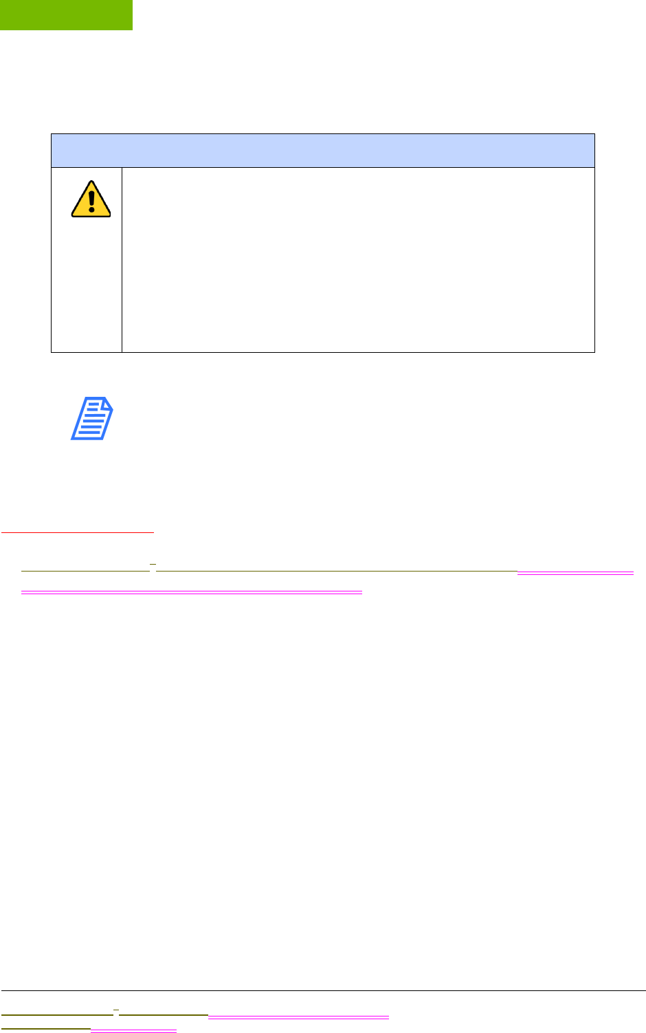
INSTALLATION
Chapter 4
Sievers M9 and M9e TOC AnalyzersSievers M5310 C TOC Analyzer Operation and Maintenance Manual
DLM 77000-01 DLM 77100-01 EN Rev. A GE Analytical Instruments © 2014
66 of 211
STEP 1: UNPACK AND INSPECT THE ANALYZER
NOTE: Save ALL original packing materials! If you need to return
the Analyzer now or in the future, you MUST pack it in the
ORIGINAL carton to ensure that no damage occurs during
shipment. Also, always insure the Analyzer in any return
shipments.
Unpack the shipping carton(s) and verify that the shipment contains the following
(Accessories Kits WIP):
•Sievers M9 and M9e TOC Analyzers Operation and Maintenance Manual Sievers M5310 C
TOC Analyzer Operation and Maintenance Manual
•PVC tubing(On-Line and Portable TOC Analyzers Only)
•Accessory Kit (Laboratory TOC Analyzer Only)
•Teflon tubing, with fittings
•Dispensing bottle (with attached filling fixture), and elbow fitting
•Shut-off Fitting, 1/4”
•C-flex tubing
•1/4” Teflon tubing with in-line filter (GEAI or customer provided?)
•Accessory Kit (On-Line and Portable TOC Analyzers Only)
•Tubing with filter
•Teflon tubing with fittings
•Dispensing bottle (with attached DI reservoir filling fitting)
•Shut-off fitting, 1/4”
•C-flex tubing
Warnings
Shipping boxes containing an Analyzer with built-in optional
components may weigh over 40 lb—necessitating a two-person
lift technique when handling. Such boxes are labeled with this
warning, supporting OSHA standards intended to protect
employees from injury.
We recommend that our customers use a two-person lift, and
GE requires that ALL employees use this handling technique
when lifting items weighing over 40 lb.

.................................
INSTALLATION INSTRUCTIONS
Sievers M9 and M9e TOC AnalyzersSievers M5310 C TOC Analyzer Operation and Maintenance Manual
DLM 77000-01 DLM 77100-01 EN Rev. A GE Analytical Instruments © 2014
67 of 211
•1/4” Teflon tubing with in-line filter (GEAI or customer provided?)
•Waste outlet fitting
•Certificate of Calibration
•DataGuard Activation key (optional)
•Reagents carton (shipped separately)
Additional Equipment Requirements
You will also need to provide the following for the installation process:
•ESD protection
•3/4” OD plastic tubing for the waste outlet (in kit or customer supplied??)
•Ethernet cable (optional)
(On-Line TOC Analyzer Only)
•Conduit connector (strain relief hubs) for power conduit wiring
•Sealing washer for conduit connector
•Ring terminal for AC conduit ground wire, 16-14 American Wire Gauge (AWG)
•Insulated wire for AC power conduit1 (18-12 AWG), rated to 300 Volts. Strip length should
be 8-9 mm (.33 in.) (Metallic conduit is required for the Analyzer to meet CE Mark electrical
requirements.)
•External circuit breaker or switch that disconnects both poles of the supply voltage, rated
appropriately
•Strain relief hub (conduit connector) and washer for I/O wiring
•Analog (4-20 mA) recorder (optional)
•Wire for 4-20 mA and alarm output (28-16 AWG), rated to 300 Volts
(On-Line TOC Analyzer Only)
•Mounting hardware to support the Analyzer — Mounting bolts should support four times
the weight of the Analyzer [Total of 64.20 kg (141.50 lb)]. For more information, see “Step 3:
Select a Location for the Analyzer.”
(Portable TOC Analyzer Only)
•Analog (4-20 mA) recorder (optional)
1. Metallic conduit is required for the Analyzer to meet CE Mark electrical requirements.

INSTALLATION
Chapter 4
Sievers M9 and M9e TOC AnalyzersSievers M5310 C TOC Analyzer Operation and Maintenance Manual
DLM 77000-01 DLM 77100-01 EN Rev. A GE Analytical Instruments © 2014
68 of 211
STEP 2: COMPLETE THE IDENTIFICATION RECORDS
Complete the Identification Records information on page 4 by recording the Analyzer serial
number and the date of installation. The serial number is located on the rear outside panel of
Laboratory and Portable TOC Analyzers, and on the left outside panel of the On-Line TOC
Analyzer.
STEP 3: SELECT A LOCATION FOR THE ANALYZER
The enclosure for the On-Line TOC Analyzer is rated IP 45 to withstand the hazards of
industrial process environments. The Portable TOC Analyzer is rated (a WIP) IP 21 for
incidental exposure to water.
Select a location away from direct sunlight and extreme temperatures. Avoid operating at
elevated temperatures greater than 40 °C, which can prevent proper operation. Also avoid
operating at temperatures lower than 10 °C, which can cause errors in the measurements.
Make sure that the back of the Analyzer is protected from water spray to ensure the electrical
and data connections remain dry.
In addition to these general instructions, refer to the sections that follow for information
pertaining to the specific model of your Analyzer.
Sievers On-Line TOC Analyzer
Sievers M9 or M9e On-Line TOC Analyzers are designed to be mounted on a wall or support
stand. When selecting the location, mount the Analyzer so that the display screen is
approximately at eye-level. For illustrations of required clearances, see Figures 15, 16, and 17.
Allow a minimum of 5 cm clearance between the back of the Analyzer and the wall for heat
dissipation. Plan for 30.5 cm of clearance on the sides, top, and bottom of the Analyzer for the
plumbing and electrical connections. This clearance provides for the proper circulation for
temperature and humidity control.
You will need to provide hardware for mounting the Analyzer on a wall or instrument rack, as
hardware should be selected based on site-specific circumstances. Choose mounting bolts
to support four times the weight of the unit2 [total = 65.68 kg (144.80 lb)].
2. 4 x 26.42 kg = 65.68 kg (4 x 35.2 lb = 144.80 lb)
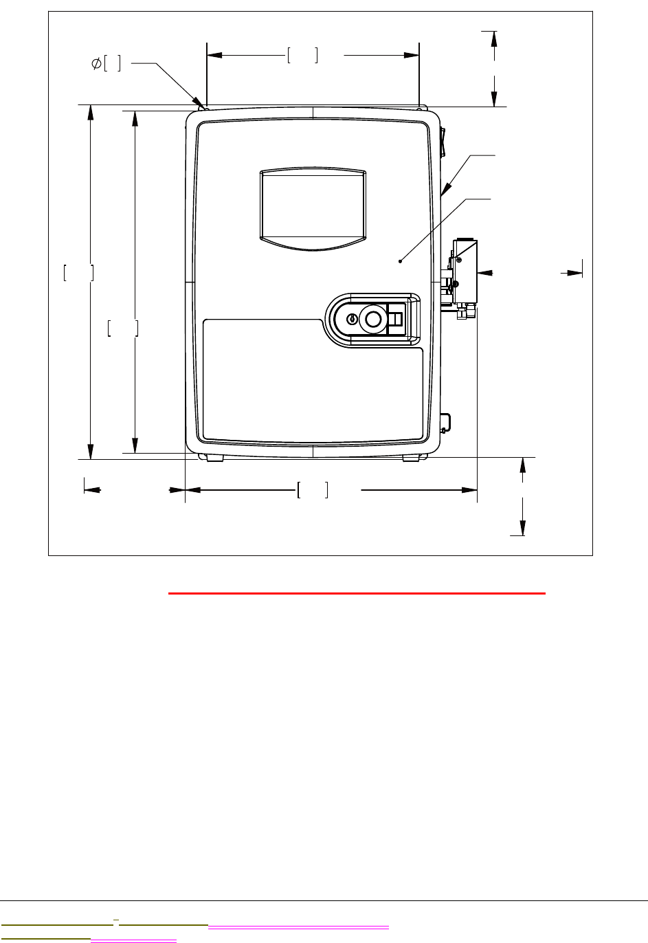
.................................
INSTALLATION INSTRUCTIONS
Sievers M9 and M9e TOC AnalyzersSievers M5310 C TOC Analyzer Operation and Maintenance Manual
DLM 77000-01 DLM 77100-01 EN Rev. A GE Analytical Instruments © 2014
69 of 211
Figure 15: Required Installation Clearances — On-Line TOC Analyzer
450
17.70
327
12.9
527
20.8
546
21.5
4X
8
.3
[305]12.0
[305]12.0
[305]12.0
[305]12.0
[450]17.7
IN FRONT
[50]2.0
IN BACK
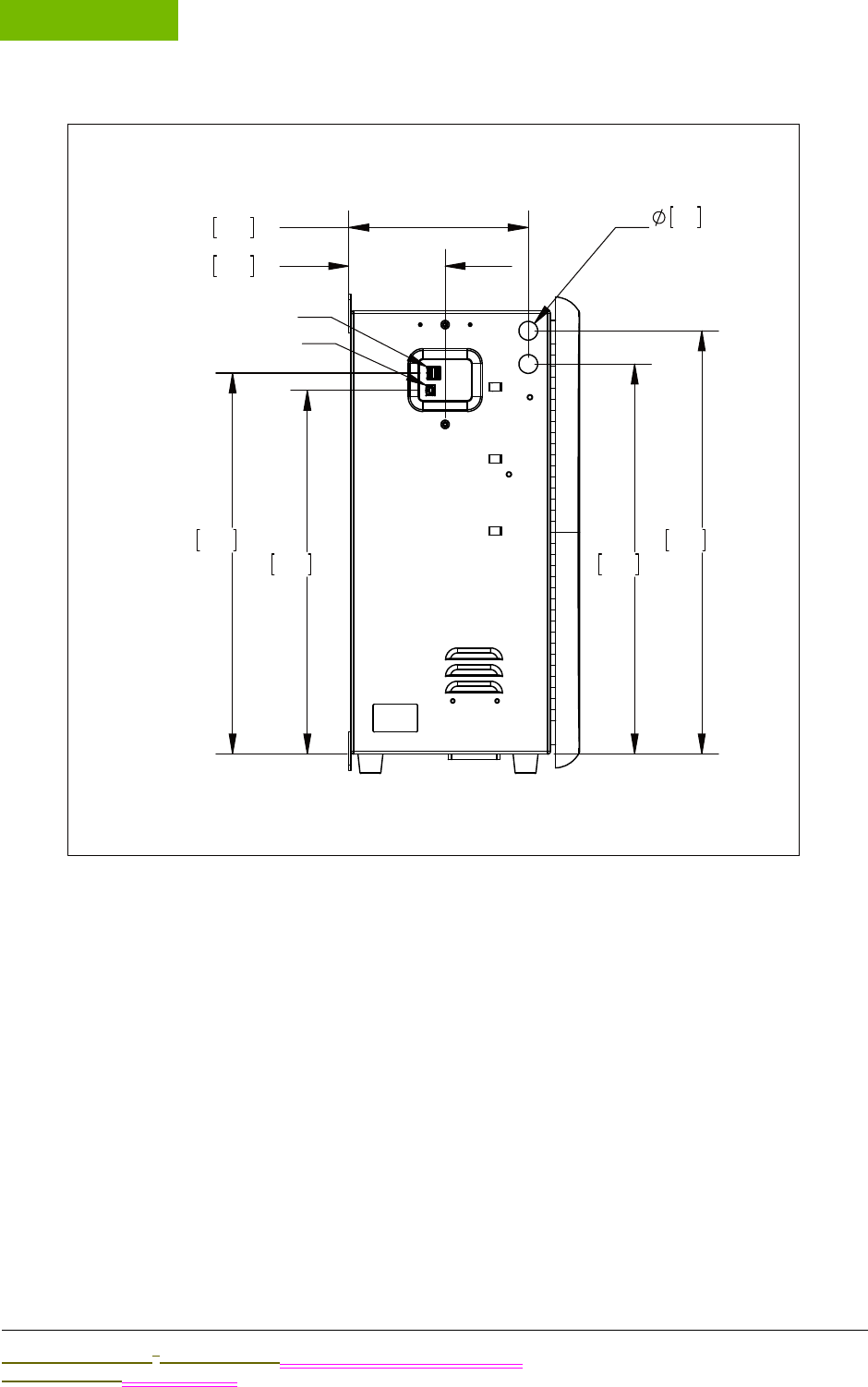
INSTALLATION
Chapter 4
Sievers M9 and M9e TOC AnalyzersSievers M5310 C TOC Analyzer Operation and Maintenance Manual
DLM 77000-01 DLM 77100-01 EN Rev. A GE Analytical Instruments © 2014
70 of 211
Figure 16: Left Side Dimensions — On-Line TOC Analyzer
111
4.4
206
8.1
447
17.6
485
19.1
21
.8
DATA INLETS
417
16.4
437
17.2
USB HOST PORTS
USB DEVICE PORT
.................................
INSTALLATION INSTRUCTIONS
Sievers M9 and M9e TOC AnalyzersSievers M5310 C TOC Analyzer Operation and Maintenance Manual
DLM 77000-01 DLM 77100-01 EN Rev. A GE Analytical Instruments © 2014
71 of 211
Figure 17: Right Side Dimensions — On-Line TOC Analyzer
Sievers Laboratory and Portable TOC Analyzers
The Analyzer is designed to be operated right-side up, resting on the rubber feet. Place the
Analyzer on a clean, unobstructed surface that can accommodate the instrument’s
dimensions and weight. For information regarding the specific specifications for your
Analyzer model, refer to the corresponding model section under Chapter 2, "System
Specifications." . Also, for proper heat dissipation, ensure that 16 cm is available at the rear
and on both sides of the Analyzer.
265
10.4
508
20.0
197
7.8
419
16.5
89
3.5
22
.9
21
.8
POWER INLET
156
6.1
142
5.6
1/4" OD SWAGELOK
INLET FITTING
1/2" ID WASTE TUBE
INSTALLATION
Chapter 4
Sievers M9 and M9e TOC AnalyzersSievers M5310 C TOC Analyzer Operation and Maintenance Manual
DLM 77000-01 DLM 77100-01 EN Rev. A GE Analytical Instruments © 2014
72 of 211
ON-LINE SAMPLING
For on-line sampling in the Portable TOC Analyzer, place the Analyzer within 3 m of the
sampling port or beaker to be tested.
GE AUTOSAMPLER SYSTEM
If you will be using the Analyzer with an Autosampler system, allow approximately 1” of
space between the GE Autosampler and Analyzer to ensure the proper functioning of both
instruments. The front edge of the Autosampler should be parallel with the front edge of the
Analyzer. Also, plan for room to accommodate a computer and (if applicable) a printer near
the Analyzer and Autosampler. For more details, refer to the
GE Autosampler Installation Guide.
STEP 4: INSTALL POWER AND I/O CONTROL WIRING
This section contains information about how to install power to the Analyzer. Both the
Laboratory and Portable TOC Analyzers come supplied with power cords. The On-Line TOC
Analyzer requires the installation of conduit to provide an external source of AC power, which
is connected to the enclosure using a water-tight conduit connector. This type of electrical
connection should be performed by a qualified electrician.
This section also includes instructions for installing I/O control wiring, including: I/O controller
board connections, 4-20 mA outputs, alarm outputs, and binary remote start and stop.
The following step-by-step instructions are included for guiding the installation process:
•Installing the Power Source
•Power Cord Installation (Laboratory and Portable TOC Analyzers)
•Power Conduit Installation (On-Line TOC Analyzer)
•On and Off Powering Guidelines
•Installing I/O Control Wiring
Warning
To avoid damaging the DI water pump, Do NOT turn the
Analyzer to On until Step 6: Install the DI Water System, after you
have completed Steps 5-7 to ensure the DI water reservoir is
filled and properly primed, as described in Step 6: Install the DI
Water System.
.................................
INSTALLATION INSTRUCTIONS
Sievers M9 and M9e TOC AnalyzersSievers M5310 C TOC Analyzer Operation and Maintenance Manual
DLM 77000-01 DLM 77100-01 EN Rev. A GE Analytical Instruments © 2014
73 of 211
•I/O Controller Board Connections
•4-20 mA Outputs
•Alarm Outputs
•Binary Remote Start/Stop
Installing the Power Source
Instructions for connecting to a power source follow. Proceed to the section that applies to
your specific model of Analyzer:
•Laboratory and Portable Analyzers — “Power Cord Installation” section
•On-Line Analyzers — “Conduit Installation” section
POWER CORD INSTALLATION
(Laboratory and Portable TOC Analyzers Only)
The Sievers M9 and M9e Laboratory and Portable Analyzers Sievers M5310 C Laboratory and
Portable TOC Analyzers come supplied with power cords. Attach the connector end of the
power cord into the connection labeled “Power” on the Analyzer, and then insert the plug end
into a grounded power source. Make sure the cord is seated securely at both ends.
CONDUIT INSTALLATION
(On-Line TOC Analyzer Only)
The Sievers M9 or M9e On-Line TOC Analyzers requireSievers M5310 C On-Line TOC Analyzer
requires the installation of an external source of AC power connected to the enclosure using
a water-tight conduit connector. The electrical connection MUST be performed by a qualified
electrician. We recommend an external switch or circuit breaker to facilitate maintenance
and servicing of the Analyzer. Install it near the Analyzer and clearly mark it as the
disconnecting device for the Analyzer.
Warning
The Analyzer requires an A/C mains supply of 100-240 volts, and
requires the correct power cord for safe operation. ONLY use the
power cord supplied in the Analyzer’s Accessory Kit with the
Analyzer, which meets this A/C mains supply requirement.
INSTALLATION
Chapter 4
Sievers M9 and M9e TOC AnalyzersSievers M5310 C TOC Analyzer Operation and Maintenance Manual
DLM 77000-01 DLM 77100-01 EN Rev. A GE Analytical Instruments © 2014
74 of 211
To wire the AC conduit
You will need to provide the following:
•Insulated wire for AC power conduit (18-12 AWG), rated to 300 Volts. Strip
length should be 8-9 mm (.33 in.).
•Metallic AC power conduit3 (optional)
•Strain relief hub (conduit connector) and washer
•Terminal ring for AC conduit ground wire, 16-14 American Wire Gauge (AWG)
•External circuit breaker or switch that disconnects both poles of the supply
voltage, rated appropriately (recommended)
1. Before working with any of the Analyzer’s inside components, ensure that you are
exercising ESD protection.
2. Unlatch and open the door to the Analyzer (Push the release button first).
3. Remove the electrical enclosure cover at the top of the instrument by using a
Phillips-head (crosshead) screwdriver #2 to loosen the two captive screws
securing the cover.
4. Remove the cap from the pass-through port located on the right side-panel of the
Analyzer. Squeeze the conical side of the cap, and then push it outside of the
Analyzer.
5. Route the AC power conduit1 through this same pass-through port, and secure a
strain relief hub (conduit connector) and washer to the conduit and Analyzer
bulkhead.
6. Connect the conduit Line (brown or black wire) to the bottom of the Terminal block
in the left port, and connect the Neutral (blue or white wire) in the right port. Refer
to Figure 18: Wiring AC Power Conduit.
When connecting the wire to the terminal block, loosen the screws on the front of
the block and then insert the wires as designated. Tighten the screws to secure
the wires.
Warning
Electrical conduit should be installed by a qualified electrician.
Also, before installing any wiring inside the Analyzer, make sure
you are wearing ESD protection.
3. Metallic conduit is required for the Analyzer to meet CE Mark electrical requirements
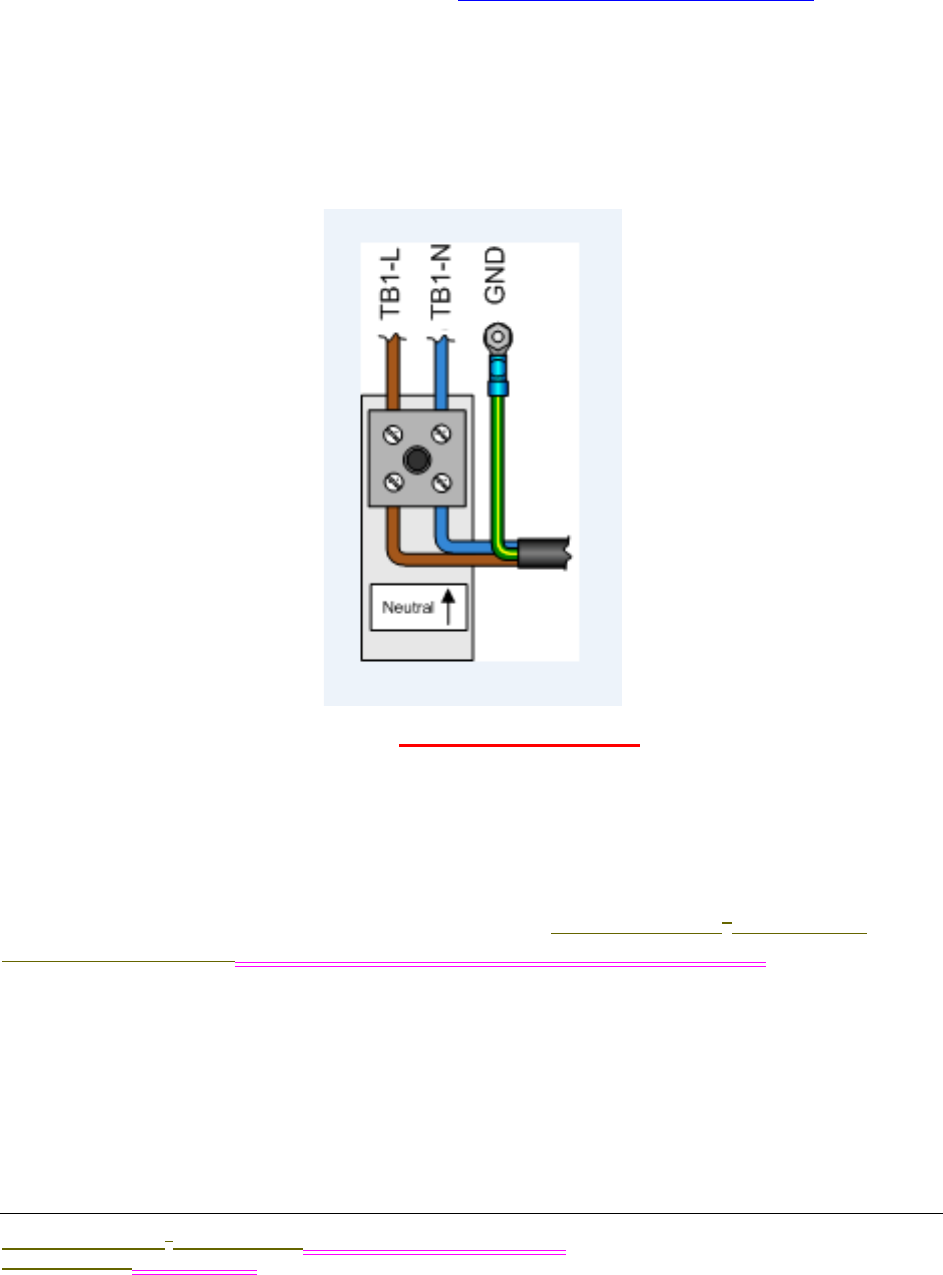
.................................
INSTALLATION INSTRUCTIONS
Sievers M9 and M9e TOC AnalyzersSievers M5310 C TOC Analyzer Operation and Maintenance Manual
DLM 77000-01 DLM 77100-01 EN Rev. A GE Analytical Instruments © 2014
75 of 211
7. After connecting the wires, pull on each connection gently to make sure the
connection is secure.
8. Attach a terminal ring to the grounding conductor (green OR green/yellow wire),
and connect it to the ground stud. Figure 18: Wiring AC Power Conduit.
9. Replace the electrical enclosure cover at the top of the instrument, and using a
Phillips-head (crosshead) screwdriver #2 to tighten the two captive screws for
securing the cover.
10. Close and latch the door to the Analyzer. (Or, proceed directly to the next section to
install the I/O control wiring.)
Figure 18: Wiring AC Power Conduit
Installing I/O Control Wiring
(On-Line and Portable TOC Analyzers Only)
An I/O Controller Board is available as an option in the Sievers M9 or M9e On-Line and
Portable TOC AnalyzersSievers M5310 C On-Line and Portable TOC Analyzers. With this board,
you can install up to three 4-20 mA analog outputs and four alarm outputs on the Analyzer.
Additionally, you can wire one binary input connection for communicating remote start and
stop commands to the Analyzer.
INSTALLATION
Chapter 4
Sievers M9 and M9e TOC AnalyzersSievers M5310 C TOC Analyzer Operation and Maintenance Manual
DLM 77000-01 DLM 77100-01 EN Rev. A GE Analytical Instruments © 2014
76 of 211
The J4, J5, and J6 terminal blocks contain the following:
•(J4) Serial and 4-20 mA Outputs 1-3 — Use these outputs to record Analyzer data. The
analog output is calibrated at the factory prior to shipping. Each pin has a power isolation
level of 500 V and is individually isolated, The maximum 4-20 mA load is 600 ohms.
•(J5) Binary Input — Use these connections to execute “Start Analysis” and “Stop Analysis”
commands to the Analyzer from a remote location, such as a Process Logic Control
System or Center (PLC).
•(J6) Alarm Output 1-4 — Use these outlets for alarm outputs. Each pin has a power
isolation level of 500 V and is individually isolated. The maximum load for the alarm ports
is 30 VDC at 1.0 A or 125 VAC at 0.5 A.
INSTALLING SERIAL AND 4-20 MA ANALOG OUTPUTS
This section includes step-by-step instructions for wiring 4-20 mA and alarm connections.
Pinout Tables and Wiring Diagrams are also provided for your reference.
To install 4-20 mA and alarm outputs — On-Line TOC Analyzer
Use this instruction to install 4-20 mA and alarm output connections on the I/O board
inside the On-Line TOC Analyzer.
You will need a small flat-blade screwdriver and wire to complete this procedure. The
wire should be 28-16 AWG, rated to 300 Volts. The strip length for each pin should be
8-9 mm (.33 in).
1. Before working with any of the Analyzer’s inside components, ensure that you are
exercising ESD protection.
2. To access the I/O board, open the door to the Analyzer (push the release button
and then pull the tab to unlatch). Remove the enclosure cover located on the back
of the door by using a Phillips-head (crosshead) screwdriver #2 to loosen the two
captive screws securing the cover. The I/O board is located behind the inside panel
of the Analyzer’s door, and the board is mounted in the lower-left area of the door.
3. Remove the cap from the pass-through cut-out (labeled “XXX” Decision not final),
located on the left side-panel. Squeeze the conical side of the cap, and then push it
out of the Analyzer.
Warning
The output and alarm connections should be installed by a
qualified electrician. Also, before installing any wiring inside the
Analyzer, make sure you are wearing ESD protection.

.................................
INSTALLATION INSTRUCTIONS
Sievers M9 and M9e TOC AnalyzersSievers M5310 C TOC Analyzer Operation and Maintenance Manual
DLM 77000-01 DLM 77100-01 EN Rev. A GE Analytical Instruments © 2014
77 of 211
4. Route the cables to the terminal blocks through this pass-through port. Terminal
block J4 is designated for 4-20 mA outputs and terminal block J6 is for the alarm
outputs.
To install the wires in a terminal block, first remove it from the I/O board. Note the
orientation of the terminal block before removing it, and then firmly grasp the
terminal block and pull it straight out from the terminal header on the board.
5. Identify the correct pin position for each wire you are installing according to Tables
2 and 3.
6. Use a small, flat blade screwdriver to completely loosen the screw for that pin. (The
screws are located underneath the terminal block.) Insert the wire into the clamp
for the pin (located on the side of the terminal block), and then tighten the pin
screw to secure the wire.
7. Repeat steps 5 and 6 for each pin you will be using.
8. Gently pull on each connection to make sure the connection is secure.
9. Plug the terminal block into the terminal header on the I/O board.
10. Repeat steps through 9 for each terminal block, as needed.
To install 4-20 mA and alarm outputs — Portable TOC Analyzer
You will need a small flat-blade screwdriver, a #2 Phillips head screwdriver, and wire to
complete this procedure. The wire should be 28-16 AWG, rated to 300 Volts. The strip
length for each pin should be 8-9 mm (.33 in).
1. Before working with any of the Analyzer’s inside components, ensure that you are
exercising ESD protection.
2. To access the I/O board, detach the protective cover from the rear of the
instrument by removing the two Phillips-head screws.
The I/O board is mounted perpendicular to the back of the Analyzer, and the
terminal blocks extend outside the instrument through cutouts in the housing.
These terminal blocks are accessible from the back of the instrument and are
labeled “Alarms,” “Binary,” and “4-20 mA.”
3. To install the wires in a terminal block, first pull out the terminal block for ease in
the installation process. Note the orientation of the terminal block before removing
it, and then firmly grasp the terminal block and pull it straight out from the
terminal header on the board.
4. Identify the correct pin location for each wire you are installing according to Tables
2 and 3.
5. Use a small flat-blade screwdriver to completely loosen the screw for that pin. The
screws are located underneath the terminal block. Insert the wire into the clamp
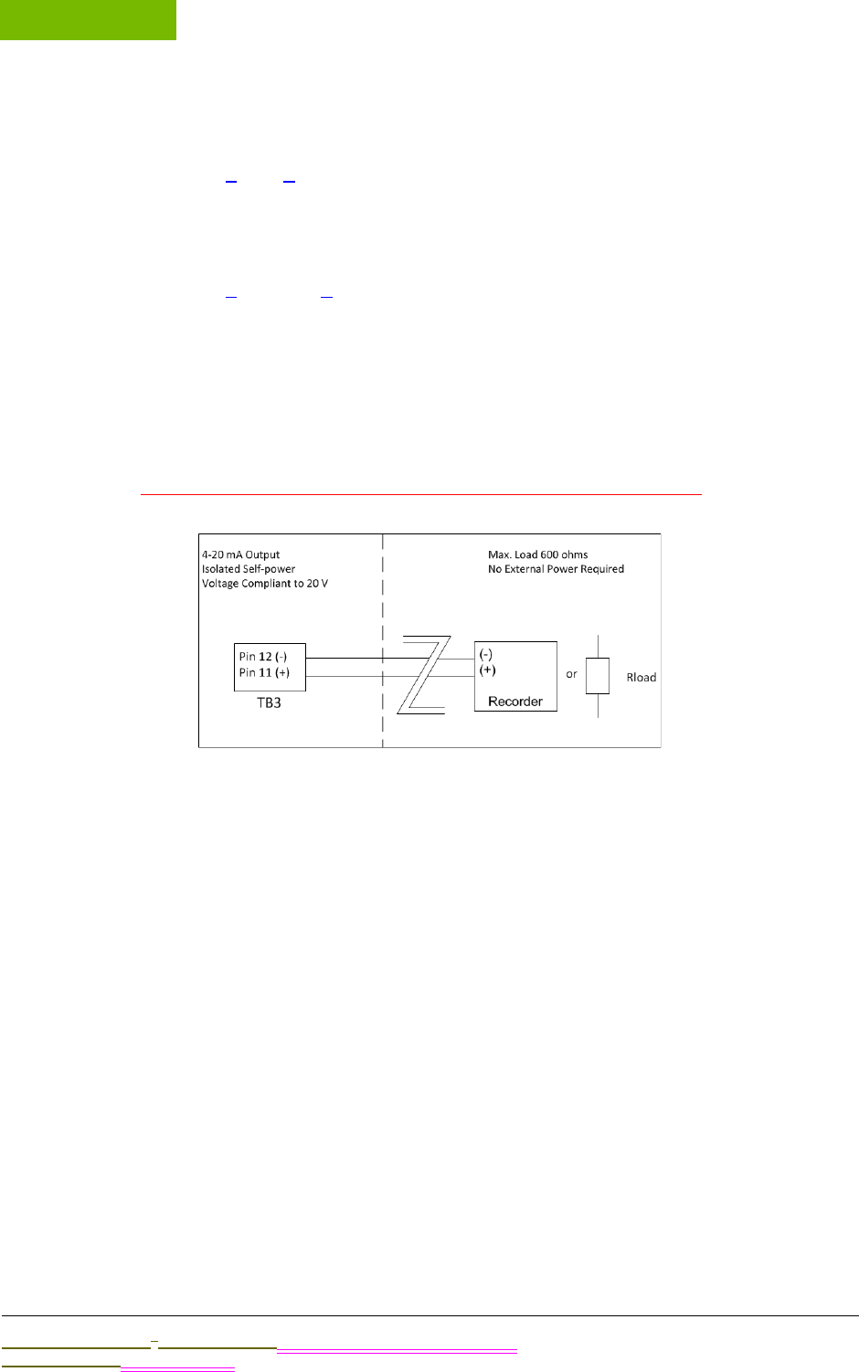
INSTALLATION
Chapter 4
Sievers M9 and M9e TOC AnalyzersSievers M5310 C TOC Analyzer Operation and Maintenance Manual
DLM 77000-01 DLM 77100-01 EN Rev. A GE Analytical Instruments © 2014
78 of 211
for the pin (located on the side of the terminal block), and then tighten the pin
screw to secure the wire.
6. Repeat steps 4 and 5 for each pin you will be using.
7. Gently pull on each connection to make sure the connection is secure.
8. Plug the terminal block into the terminal header on the I/O board.
9. Repeat steps 3 through 8 for each terminal block, as needed.
10. Replace the Analyzer’s enclosure panel, making sure that the magnets are
secured.
PINOUT TABLES AND WIRING DIAGRAMS
Reference the following information, as needed, when wiring 4-20 mA outputs and
alarms. Allen providing new wiring diagrams from Mike Cunningham.
Figure 19: Wiring 4-20 mA Connections
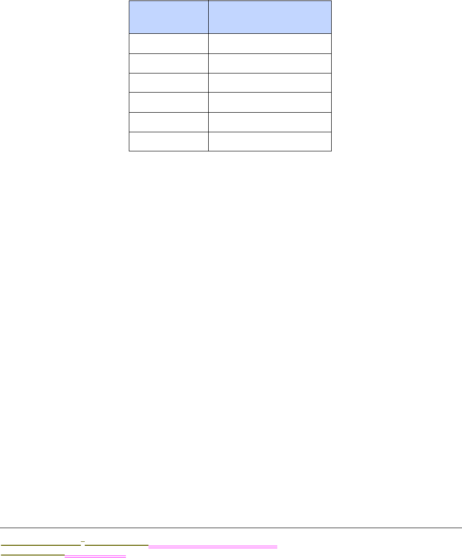
.................................
INSTALLATION INSTRUCTIONS
Sievers M9 and M9e TOC AnalyzersSievers M5310 C TOC Analyzer Operation and Maintenance Manual
DLM 77000-01 DLM 77100-01 EN Rev. A GE Analytical Instruments © 2014
79 of 211
J4 Board Wiring
The 4-20 mA analog outputs are isolated from system ground. You can configure the
analog outputs to output IC, TC, or TOC.
The 4-20 mA outputs are also individually isolated from each other, and therefore may
be connected to multiple industrial control systems (ICS) with differences in ground
potential.
.
TABLE 2: SERIAL AND 4-20 MA OUTPUTS (J4)
Pin Number Output
1 #1 4-20 mA (Return) -
2 #1 4-20 mA (Out) +
3 #2 4-20 mA (Return) -
4 #3 4-20 mA (Out) +
5 #3 4-20 mA (Return) -
6 #3 4-20 mA (Out) +
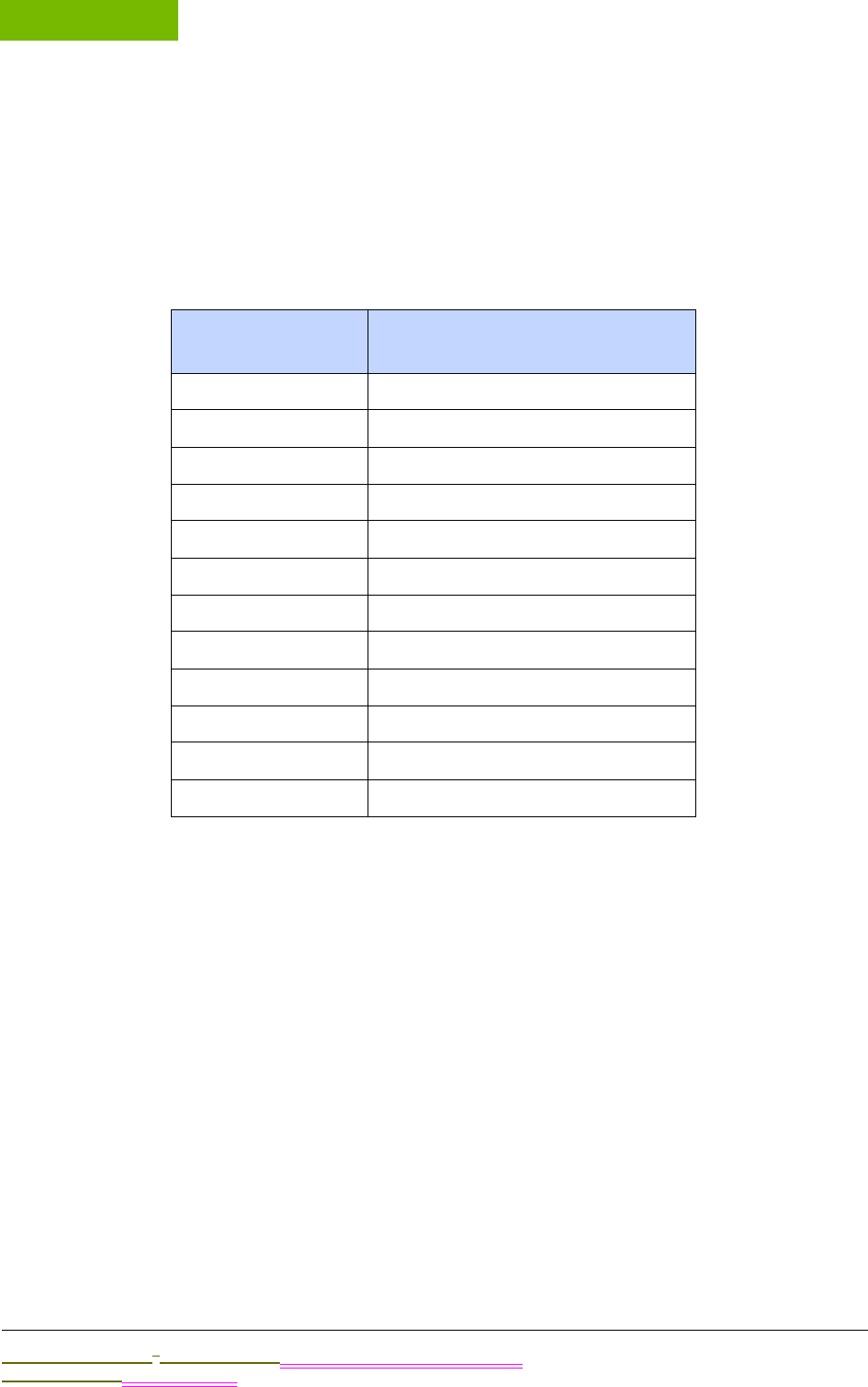
INSTALLATION
Chapter 4
Sievers M9 and M9e TOC AnalyzersSievers M5310 C TOC Analyzer Operation and Maintenance Manual
DLM 77000-01 DLM 77100-01 EN Rev. A GE Analytical Instruments © 2014
80 of 211
J6 Board Wiring
The alarm outputs are isolated from system ground and from each other. You can
configure each of the alarm outputs.
The outputs are implemented by relays, which are intended for low voltage use only.
The maximum switching capacity (resistive load) is 62.5 VA, 33 Watts.
* NC = normally closed, NO = normally open
INSTALLING THE REMOTE START (BINARY INPUT) CONNECTION
The remote start (binary input) connection is intended to execute “Start Analysis” and
“Stop Analysis” commands to the Analyzer from a remote location, such as a Process Logic
Control System or Center (PLC).
J5 Board Wiring
The J5 terminal block is used for the binary input. Refer to Table 20, “Wiring Option for
Binary Input Using Analyzer’s Internal Supply for the pin references.
The binary start/stop analysis input is isolated from system ground. You can configure the
polarity of operation.
The + input should be supplied with a voltage from +11 volts to +24 volts and the -input
should be controlled by a relay or an open collector transistor.
TABLE 3: ALARM OUTPUTS (J6)
Pin Number Outputs
1 Alarm 1 (Common) output
2 Alarm 1 (NC*) output
3 Alarm 1 (NO*) output
4 Alarm 2 (Common) output
5 Alarm 2 (NC*) output
6 Alarm 2 (NO*) output
7 Alarm 3 (Common) output
8 Alarm 3 (NC*) output
9 Alarm 3 (NO*) output
10 Alarm 4 (Common) output
11 Alarm 4 (NC*) output
12 Alarm 4 (NO*) output
.................................
INSTALLATION INSTRUCTIONS
Sievers M9 and M9e TOC AnalyzersSievers M5310 C TOC Analyzer Operation and Maintenance Manual
DLM 77000-01 DLM 77100-01 EN Rev. A GE Analytical Instruments © 2014
81 of 211
TABLE 4: BINARY INPUTS (TERMINAL BLOCKJ5)
NOTE: The +24 volts (0.5A max) and system ground are provided for
local use only and are not intended for connections more than 15 ft
away from the analyzer.
To install the binary input connections
You can wire the binary input connection in a variety of ways, such as the examples
shown in Figure 20: Wiring Option for Binary Input Using Analyzer’s Internal Supply
and Figure 21: Wiring Option for Binary Input Using External Supply.
Before using the binary input connection, you must activate the Binary Input feature in
the Analyzer firmware. You will do this later during the installation process in “Step 10:
Configure Basic Analyzer Settings” on page 98.
NOTE: Make sure to confirm the correct signal strength before setting
the Binary Input to On in order to avoid unexpectedly starting or
stopping analysis.
Figure 20: Wiring Option for Binary Input Using Analyzer’s Internal Supply
Figure 21: Wiring Option for Binary Input Using External Supply
Pin Number Output
1 +24 V
2In+
3In-
4GND
INSTALLATION
Chapter 4
Sievers M9 and M9e TOC AnalyzersSievers M5310 C TOC Analyzer Operation and Maintenance Manual
DLM 77000-01 DLM 77100-01 EN Rev. A GE Analytical Instruments © 2014
82 of 211
STEP 5: INSTALL THE REAGENT CARTRIDGES
The oxidizer and acid reagents are shipped separately from GE Analytical Instruments in
specific packaging for safe transit. Carefully read the attached MSDS sheets prior to opening
the packaging. You will find two reagent cartridges inside the packaging, one clearly
identified as “OXIDIZER (15% ammonium persulfate and water” and one as “UN 1805
PHOSPORIC ACID SOLUTION.”
After you install these reagent cartridges, the RFID antenna obtains and tracks data from
each label attached to the Acid and Oxidizer reservoir cartridges, including: Reagent type
(Acid or Oxidizer), lot number, part number, initial and remaining volume, manufactured date
and expiration date. The Analyzer uses this information to automatically track the remaining
volume, based on the number of syringe extractions. For additional information, see “Radio
Frequency ID (RFID)” on page 57.
The following instructions are specific to the Analyzer model. Refer to the applicable section
for your instrument:
•To install the reagent cartridges—Laboratory and Portable TOC Analyzers
•To install the reagent cartridges—On-Line TOC Analyzer
Know These Safety Warnings
Hazardous reagents (ammonium persulfate and phosphoric
acid) are used in the Analyzer. Before installing a reagent, read
the corresponding Material Safety Data Sheet (MSDS) for proper
handling precautions, and spill or leak procedures. The MSDS are
contained in the pouch located on the outside of the reagent
shipping box.
Installation of reagents and most Analyzer maintenance
requires access to the inside of the Analyzer. To avoid potentially
dangerous shock—BEFORE opening the Analyzer—first stop any
analysis, stop the operating system (using HALT SYSTEM button in
the Analyzer’s firmware), and then turn off power and
disconnect from the power supply.
To avoid exposure to the chemical reagents, wear acid-resistant
gloves and safety goggles.
Reagent containers are for single-use only. Do NOT refill. Any
refilling or reusing of reagent containers will void all Analyzer
and parts warranties, and nullify any performance claims.

.................................
INSTALLATION INSTRUCTIONS
Sievers M9 and M9e TOC AnalyzersSievers M5310 C TOC Analyzer Operation and Maintenance Manual
DLM 77000-01 DLM 77100-01 EN Rev. A GE Analytical Instruments © 2014
83 of 211
To install the reagent cartridges—Laboratory and Portable TOC
Analyzers
1. Before opening and working with the chemical reagents, and working inside the
Analyzer, ensure that you are:
•Ensure that Analyzer switch is Off and the power cord is disconnected. (You
MUST always Halt the firmware before turning the power switch to Off.)
•Wearing the recommended personal protective equipment (PPE), as outlined in
the previous Safety Warning
•Exercising electrostatic discharge (ESD) protection
2. Open the Analyzer, as follows:
•(Laboratory TOC Analyzer) — Remove the right side panel. Stabilize the
instrument with one hand on the top panel, and then grasp the edge of the
right side panel from the back of the Analyzer. Pull the entire panel away from
the instrument. (The panel is attached to Analyzer by magnets.)
•Portable TOC Analyzer — Remove the right side panel. Stabilize the instrument
with one hand on the top handle, and then grasp the edge of the panel from the
back of the Analyzer. Pull the entire right panel away from the instrument. (The
panel is attached to Analyzer by magnets.)
3. Locate and remove the reagent tray, and set it next to the Analyzer for the
assembly process. Position the labeled side toward you with the cut-out end
pointed toward the left (the front of the Analyzer).
The tray is attached by magnets to the RFID antenna4 (rectangular) cover, which is
located on the floor of the unit.
4. Remove each reagent container from its shipping packaging.
5. Stand each container on the long end next to the Analyzer for this connection
process.
Place the Oxidizer container in front position (for the convenience of earlier
replacement anticipated by typical consumption timing).
6. Locate the acid supply line, indicated by the Acid label. Attach the supply-line PEEK
nut to the inlet at the top of the acid reagent container, and then tighten finger-
tight. Verify if Engineering is adding Acid label.
(Delete later when new cartridge is implemented.) Slide the valve on the acid
container to the open position by pushing the green button all the way in. Refer to
the labeling on the container for proper positioning.
7. Locate the oxidizer supply line, indicated by the Oxidizer label. Attach the supply-
line PEEK nut to the oxidizer container and tighten finger-tight.
4. Radio Frequency ID used to track expiration dates off the reagent containers.

INSTALLATION
Chapter 4
Sievers M9 and M9e TOC AnalyzersSievers M5310 C TOC Analyzer Operation and Maintenance Manual
DLM 77000-01 DLM 77100-01 EN Rev. A GE Analytical Instruments © 2014
84 of 211
(Delete later when new cartridge is implemented.) Slide the valve on the oxidizer
container to the open position by pushing the green button all the way in. Refer to
the labeling on the container for proper positioning.
8. Verify that the labeled side of the reagent tray is facing you and the cut-out side of
the tray is facing left toward the front of the Analyzer.
9. Place the Acid container into the back compartment of the reagent tray, and then
place the Oxidizer container into the front compartment of the reagent tray. Make
sure to position the tubing-end of each container toward the cut-out side of the
tray.
10. Now, lift the entire reagent tray (with the Acid and Oxidizer containers in place),
and set the tray back on the RFID antenna5 (rectangular) cover, which is located on
the floor of the unit. The magnet feet of the tray fit into the corner grooves on the
RFID cover. You will feel the magnets secure the tray into place.
NOTE: When installing the reagent tray, make sure the labeled
side of the tray is facing you and the tubing-ends of the reagent
containers are pointed left (toward the front of the Analyzer).
11. You will flush the reagent syringes later in the installation process, as described in
“To flush the reagent syringes” on page 105,
To install the reagent cartridges—On-Line TOC Analyzer
1. Before opening and working with the chemical reagents, and working inside the
Analyzer, ensure that:
•The Power switch is Off and the power cord is disconnected (Laboratory and
Portable TOC Analyzers), or the Mains turned off (On-Line TOC Analyzer). (You
MUST always Halt the firmware to turn off power to the Analyzer.)
•You are wearing the recommended personal protective equipment (acid-
resistant gloves and safety goggles).
•You are Exercising electrostatic discharge (ESD) protection
1. Open the door to the Analyzer. Push the release button and then pull the tab to
unlatch the door.
2. Loosen the thumbscrews on the reagent housing cover, which is located on the
(lower front) floor of the Analyzer. Lift the cover straight up to remove, and then set
aside the cover during the assembly process.
3. Remove each reagent container from its shipping packaging.
5. Radio Frequency ID used to track expiration dates off the reagent containers.
.................................
INSTALLATION INSTRUCTIONS
Sievers M9 and M9e TOC AnalyzersSievers M5310 C TOC Analyzer Operation and Maintenance Manual
DLM 77000-01 DLM 77100-01 EN Rev. A GE Analytical Instruments © 2014
85 of 211
4. Locate the acid supply line, indicated by the Acid label. Attach the supply-line PEEK
nut to the inlet at the top of the acid reagent container, and then tighten finger-
tight. Verify if Engineering is adding Acid label.
(Delete later when new cartridge is implemented.) Slide the valve on the acid
container to the open position by pushing the green button all the way in. Refer to
the labeling on the container for proper positioning.
5. Place the Acid container into the back compartment of the reagent tray,
positioning the container horizontally with the tubing-end facing toward the right
and open-side of the tray.
6. Locate the oxidizer supply line, indicated by the Oxidizer label. Attach the supply-
line PEEK nut to the oxidizer container and tighten finger-tight.
(Delete later when new cartridge is implemented.) Slide the valve on the oxidizer
container to the open position by pushing the green button all the way in. Refer to
the labeling on the container for proper positioning.
7. Place the Oxidizer container into the front compartment of the reagent tray,
positioning the container horizontally with the tubing-end facing toward the right
and open-side of the tray.
8. Carefully lower the reagent housing cover over the reagents, sliding the guide pin
(located toward the back and on top of the reagent cradle) through the guide hole
on the cover.
Also, make sure that the two tubing lines are carefully positioned between the
cover and cradle-side cushions.
9. Tighten the thumbscrews on the reagent housing cover to secure.
10. You will flush the reagent syringes later in the installation process, as described in
“To flush the reagent syringes” on page 105,
STEP 6: INSTALL THE DI WATER SYSTEM
The Analyzer is shipped with an empty DI water reservoir and a (separately-packed) DI resin
cartridge. You will need to fill the DI water reservoir with DI water. Next, you will need to install
the DI resin cartridge into the Prime position and prime the DI water pump. After the priming
process, you will move the DI resin cartridge into the Run position for normal Analyzer
operation.
Warning
To avoid damaging the DI water pump, Do NOT turn the
Analyzer to On before ensuring that the DI water reservoir is
filled and properly primed, as described in Step 6: Install the DI
Water System.

INSTALLATION
Chapter 4
Sievers M9 and M9e TOC AnalyzersSievers M5310 C TOC Analyzer Operation and Maintenance Manual
DLM 77000-01 DLM 77100-01 EN Rev. A GE Analytical Instruments © 2014
86 of 211
NOTE: Each port (Prime, Run, and DI Pump Outlet) has a metal
latch to use when inserting and detaching a fitting. Press the latch
and hold when inserting a fitting. This protects the fitting and
opens the valve. Press the latch with your finger to release a
fitting and close the valve. When inserting or detaching the DI
resin cartridge, insert or detach both end-fittings simultaneously
to avoid damaging movement to the cartridge.
To fill the DI water reservoir
1. Before working inside the Analyzer, ensure that:
•The Power switch is Off and the power cord is disconnected (Laboratory and
Portable TOC Analyzers), or the Mains turned off (On-Line TOC Analyzer). (You
MUST always Halt the system in the firmware before pressing the power switch
to Off.)
•You are wearing the recommended personal protective equipment (acid-
resistant gloves and safety goggles).
•You are Exercising electrostatic discharge (ESD) protection.
2. Locate the following in the Analyzer’s Accessories Kit:
•Dispensing bottle (with attached filling fixture)
•Individual (loose) elbow fitting
You may also want to have a paper towel nearby, in case of any leakage during
the installation and priming processes.
3. Press the latch of the Prime port down and insert the individual (loose) elbow
fitting,
4. Unscrew the lid of the dispensing bottle (leaving the filling fixture attached to the
top of the lid), and fill the bottle with low-TOC (<50 ppb) DI water. Replace and
tighten the lid to secure it.
5. Press the latch of the DI pump outlet up and insert the elbow-fitting end of the
dispensing bottle into the DI pump outlet. (The outlet is located between the IC and
TC sample pumps). Reference Figure 22: Inserting the DI Loop Fill Tube.)
Gently squeeze the bottle to fill the DI reservoir, filling the DI reservoir until the
water line reaches JUST BELOW the top of the reservoir, as shown in Figure 23:
Filling the DI Water Reservoir. DO NOT OVERFILL.
NOTE: It is important to ONLY fill the reservoir to the suggested
level. Otherwise, the water in the portion of the reservoir that you
can see may overflow to another level in the reservoir (which you
cannot see from the viewing window). If you do overfill the
reservoir, drain the excess water by following the troubleshooting
.................................
INSTALLATION INSTRUCTIONS
Sievers M9 and M9e TOC AnalyzersSievers M5310 C TOC Analyzer Operation and Maintenance Manual
DLM 77000-01 DLM 77100-01 EN Rev. A GE Analytical Instruments © 2014
87 of 211
procedure, “To drain excess water from the DI water reservoir” on
page 168.
6. Press the latch of the Prime port down to release the individual elbow fitting for
removal.
7. Press the latch of the DI pump outlet up to release the dispensing bottle’s elbow-
fitting for removal of the dispensing bottle accessory.
8. Proceed to the next section to set the DI resin cartridge and prime the DI pump.
Figure 22: Inserting the DI Loop Fill Tube
graphic showing cut-out area above the IC and TC sample pumps and DI pump outlet
Figure 23: Filling the DI Water Reservoir
To set the DI resin cartridge and prime the DI pump
You will first install the DI resin cartridge into the Prime position and prime the DI
water pump, and then reset the DI resin cartridge into the Run position for normal
Analyzer operation.
1. Ensure that the DI water reservoir is filled, according to the instructions in the
previous section.
2. Locate the DI resin cartridge in the Analyzer’s Accessories kit, and remove it from
its shipping packaging.
3. Install the DI resin cartridge. Press the latches on the Prime port and the DI Pump
Outlet port. Insert the elbow-fitting ends of the cartridge into the ports.
Verify that the ends are secure before moving to the next step.
Refer to Figure 24: DI Cartridge Inlet Fittings for Priming Activity, as needed.
4. Go to the next instruction section to prime the DI water pump.
To prime the DI Water pump
Warning
In order to avoid the possibility of corrupting the system
database, always FIRST halt system operations from within the
firmware before pushing the Analyzer’s power switch to the Off
position.
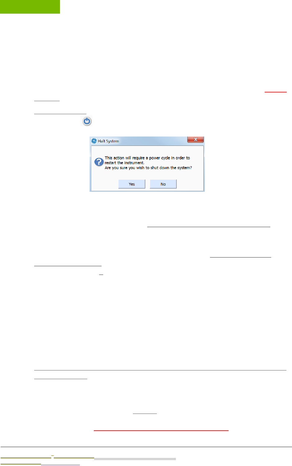
INSTALLATION
Chapter 4
Sievers M9 and M9e TOC AnalyzersSievers M5310 C TOC Analyzer Operation and Maintenance Manual
DLM 77000-01 DLM 77100-01 EN Rev. A GE Analytical Instruments © 2014
88 of 211
1. Ensure that the DI resin cartridge is set in place with the top valve securely
connected to the Prime position, according to the instructions in the previous
section.
2. Plug in the Analyzer’s power cord (Laboratory and Portable TOC Analyzers) or turn
on the Mains (On-Line TOC Analyzer).
3. Press the Analyzer’s power switch to the On position, and let the Analyzer run 10
minutes to allow the DI pump to circulate water in the DI loop.
4. After 10 minutes, on the Home screen (in the Analyzer’s firmware), press the HALT
SYSTEM button located in the lower-right portion of the screen. The Halt
System dialog box appears.
5. Turn the power switch to the Off position.
6. View the reservoir water level and verify that the water level reaches JUST BELOW
the top of the reservoir, as shown in Figure 23: Filling the DI Water Reservoir.
7. The water level may be lower than when you started, as water will circulate in the
DI loop and saturate the DI resin cartridge during the priming process. Fill the DI
reservoir with water if needed, repeating the procedure, “To fill the DI water
reservoir” on page 86. You will also need to repeat this priming procedure
beginning from step 1.
8. After you have verified the that the water level has stabilized to JUST BELOW the
top of the reservoir, remove the DI resin cartridge from the prime position. While
holding the DI cartridge, simultaneously press the latches on the Prime port and
the DI Pump Outlet port to eject the cartridge.
9. Install the DI resin cartridge into the Run position. Press the latches on the Run port
and the DI Pump Outlet port. Insert the elbow-fitting ends of the cartridge into the
ports. Hold the cartridge tightly in place.
Verify that the ends are secure before moving to the next step.
10. Do we want to run for any amount of time in Run position before moving to next
installation step?
11. Close and latch the Analyzer’s door (On-Line TOC Analyzer) or replace the panel
(Laboratory and Portable TOC Analyzers Only).
graphic.
Figure 24: DI Cartridge Inlet Fittings for Priming Activity

.................................
INSTALLATION INSTRUCTIONS
Sievers M9 and M9e TOC AnalyzersSievers M5310 C TOC Analyzer Operation and Maintenance Manual
DLM 77000-01 DLM 77100-01 EN Rev. A GE Analytical Instruments © 2014
89 of 211
graphic.
Figure 25: DI Cartridge Positioning for Analyzer Operation
STEP 7: INSTALL ETHERNET AND EXTERNAL DEVICES
Update Intro
•Installing an Ethernet connection
•Installing a Printer
•Installing USB connections
•One Device Port (ONLY Used for connecting a computer when operating with Sievers
DataPro Software.)
•Host Port (Used for connecting a GE Autosampler, printer, or portable USB memory
device.)
Installing an Ethernet Connection
You can export historical data from the Analyzer to your computer or computer network via
Ethernet, and using the Modbus communications protocol. For more information on the types
of data available for export, as well how-to instructions, refer to “Using the Ethernet
Connection and Modbus” on page 149.
This section describes installing the Ethernet connection. You will then need to activate the
Ethernet Connection in the Analyzer’s firmware later in “Step 10: Configure Basic Analyzer
Settings.” You may need more assistance from your network administrator or Information
Technology (IT) professional to configure PuTTY6 for working with exported data, or to
configure the Modbus communications protocol when you are connecting to a PLC (Process
Logic Control System or Center).
NOTE: You can alternately export data directly to your computer using a
USB device connection, and use the optional DataPro Software to work
with the data. Refer to “Installing a USB Connection” on page 90 for
additional information.
6. PuTTY is a free and open-source terminal emulator, serial console, and network file transfer
protocol.

INSTALLATION
Chapter 4
Sievers M9 and M9e TOC AnalyzersSievers M5310 C TOC Analyzer Operation and Maintenance Manual
DLM 77000-01 DLM 77100-01 EN Rev. A GE Analytical Instruments © 2014
90 of 211
To install the Ethernet Connection
You will need to provide either a cross-over Ethernet cable (for connecting directly to a
computer) or a straight-through Ethernet cable (for connecting to a computer
network).
1. Attach one end of the Ethernet cable to the Ethernet port on the Analyzer, and then
attach the other end of the cable either to an Ethernet port on the your network or
to a computer.
2. You will activate the Ethernet connection and Modbus later in “Step 10: Configure
Basic Analyzer Settings” as described in the section, “To activate the Ethernet
Connection and Modbus” on page 103.
NOTE: The USB ports on the Analyzer are NOT intended for
Ethernet connectivity, and cannot not be used with an Ethernet to
USB adapter. For acceptable uses of the USB ports, refer to the
next section “Installing a USB Connection.”
INSTALLING A USB CONNECTION
The On-Line and Portable TOC Analyzers each contain three USB ports on the back of the
instrument. One device port is labeled “USB Computer,” and two host ports are labeled “USB.”
The (Laboratory TOC Analyzer) also contains three similar USB ports on the back of the
instrument, as well as one additional USB host port on the front of the instrument, labeled
“USB.” Refer to USB port locations in Figure 26: USB Ports, as needed.
USB DEVICE PORT
The Analyzer has one USB device port (labeled “USB Computer”) for connecting the Analyzer
directly to your computer, when using the optional DataPro Software to control the Analyzer
and the GE Autosampler. The USB device port is uniquely shaped with a rounded square
connector in contrast to the typical (flat) USB host connector. A USB-device to USB-host cable
is included in the GE Autosampler Accessories Kit.
NOTE: The USB Device port is intended solely for connecting the
Analyzer to the computer for operation with the DataPro
Software. It is NOT possible to export data to a computer through
this USB Device port without the use of the DataPro Software.
You can export data from the Analyzer to a USB portable drive using
one of the Host ports or through an Ethernet connection. Refer to “USB
Host Ports” on page 91 or “Installing an Ethernet Connection” on
page 89, as needed.

.................................
INSTALLATION INSTRUCTIONS
Sievers M9 and M9e TOC AnalyzersSievers M5310 C TOC Analyzer Operation and Maintenance Manual
DLM 77000-01 DLM 77100-01 EN Rev. A GE Analytical Instruments © 2014
91 of 211
To install a USB connection — Device Port (Optional)
1. Install the DataPro Software on your computer now, or come back to and perform
this instruction after you have installed the software.
Instructions for installing the DataPro Software are included in the
GE Autosampler Installation Guide.
2. Locate one of the USB-Device to USB-Host cables in the GE Autosampler
Accessories Kit. [You will use the other cable later in this section.)
3. Connect the Device USB-Device connection end of the cable into the “Computer”
USB port on the Analyzer.
4. Connect the other end of the cable with the host USB connection end into your
computer’s USB (host) port.
5. “To install a USB Host port connection — GE Autosampler (Optional)” on page 91.]
USB HOST PORTS
The On-Line and Portable TOC Analyzers have two USB host ports (labeled “USB”) on the back
of the instrument. The (Laboratory TOC Analyzer) also contains two USB host ports (labeled
“USB”) on the back of the instrument, as well one additional USB host port (labeled “USB”) on
the front of the instrument.
The USB host ports are designed for use with the following peripheral accessories:
•GE Autosampler
•Printer (Must be one of the specific brands/models identified in the “Installing a Printer”
section.)
•Portable USB memory device
To install a USB Host port connection — GE Autosampler (Optional)
1. Complete this instruction after you have installed the DataPro Software on your
computer, or come back to and perform this instruction after you have installed
the software.
2. Ensure that you have connected the Analyzer to your computer, as described in
“To install a USB connection — Device Port (Optional)” on page 90.
3. Locate the remaining USB-Device to USB-Host cable in the GE Autosampler
Accessories Kit.
4. Connect the Device-USB connection end of the cable into the “Computer” USB port
on the GE Autosampler.

INSTALLATION
Chapter 4
Sievers M9 and M9e TOC AnalyzersSievers M5310 C TOC Analyzer Operation and Maintenance Manual
DLM 77000-01 DLM 77100-01 EN Rev. A GE Analytical Instruments © 2014
92 of 211
5. Connect the other end of the cable with the host-USB connection end into one of
the Analyzer’s USB (host) ports.
To install a USB Host port connection — Printer (Optional)
Refer to the section, “Installing a Printer” on page 92, for step-by-step instructions.
To install a USB Host port connection — Portable USB Memory Device
You can export data from the Analyzer to a portable USB memory device using any of
the USB Host ports on the Analyzer. Insert the USB memory device into a Host port,
and then follow the step-by-step instructions for exporting data history included in “”
on page 150.
Graphic for USB Ports (three models)
Figure 26: USB Ports
Installing a Printer
The Analyzer is designed to work with the following USB point-of-service (POS) printers, which
are available as an optional accessory directly from GE Analytical Instruments:
•Bixolon/Samsung SRP-275
•Citizen CD-S500A
•Epson TM-722OD
To install a USB POS printer
1. Connect the USB connector-end of the printer cable into one of the USB device
ports (marked “USB”) on the Analyzer.
2. Connect the other end of the cable into the printer.
3. Consult the instructions that come with the printer for additional help, as needed.
4. Continue to the next section to configure the printer in the Analyzer.
To configure the printer in the Analyzer
1. Connect the printer to the Analyzer, as described in the previous section.
2. On the Configuration screen, press the System Setup tab.
3. Press PRINTER SETUP to display the Printer Configuration dialog.

.................................
INSTALLATION INSTRUCTIONS
Sievers M9 and M9e TOC AnalyzersSievers M5310 C TOC Analyzer Operation and Maintenance Manual
DLM 77000-01 DLM 77100-01 EN Rev. A GE Analytical Instruments © 2014
93 of 211
4. Select one of the following printers to install:
•Bixolon/Samsung SRP-275
•Citizen CD-S500A
•Epson TM-722OD
5. Press TEST PRINT to verify that printer is working.
If the page does not print, verify that the printer you have installed is the exact
brand and model selected on the Printer Configuration dialog, and that you have
connected the cable as described in the previous section.
6. Press OK to enable the printer.
STEP 8: CONNECT AN ON-LINE SAMPLE INLET SYSTEM
(On-Line and Portable TOC Analyzers Only)
Add two-stream connection information.......The two-stream inlet option enables efficient
sampling of two independent sample sources, without the need to alter the initial inlet setup.
This optional configuration is discussed in more detail in the “Optional
Configurations”section, under “Two-Stream Inlet” on page 60.
NOTE: If you are using a GE Autosampler with your Laboratory or
Portable TOC Analyzer model, DO NOT proceed with this section.
Instead, refer to the GE Autosampler User Guide. The information for
connecting the sample tubing to the inlet port is located in the section,
“Route the Sample Tubing.”
Connect a sample inlet line to the integrated On-Line Sampling (iOS) for continuous on-line
measuring. As part of the sample-inlet installation process, you will also install a waste line.
With this inlet system installed, you can conveniently switch between on-line sampling and
discrete sampling using vials in the iOS.
There is no further installation required for On-Line and Portable TOC Analyzers to measure
discrete grab samples from a vial. The iOS is ready for measuring grab samples without the
need to disconnect the on-line inlet tubing. The Analyzer automatically shuts off on-line
water flow when it detects that the iOS door is closed and/or a vial is inserted into the iOS.
You will need to select an appropriate On-line or Grab measurement mode on the Setup
screen in the Analyzer’s firmware, and then start the sampling on the Home screen. For
complete step-by-step instructions, refer to “Running a sample” on page 126.
NOTE: The Laboratory TOC Analyzer arrives ready to measure discrete
grab samples using the vial port (located on the front) of the instrument.
It is not designed for continuous on-line sampling. Go to the next
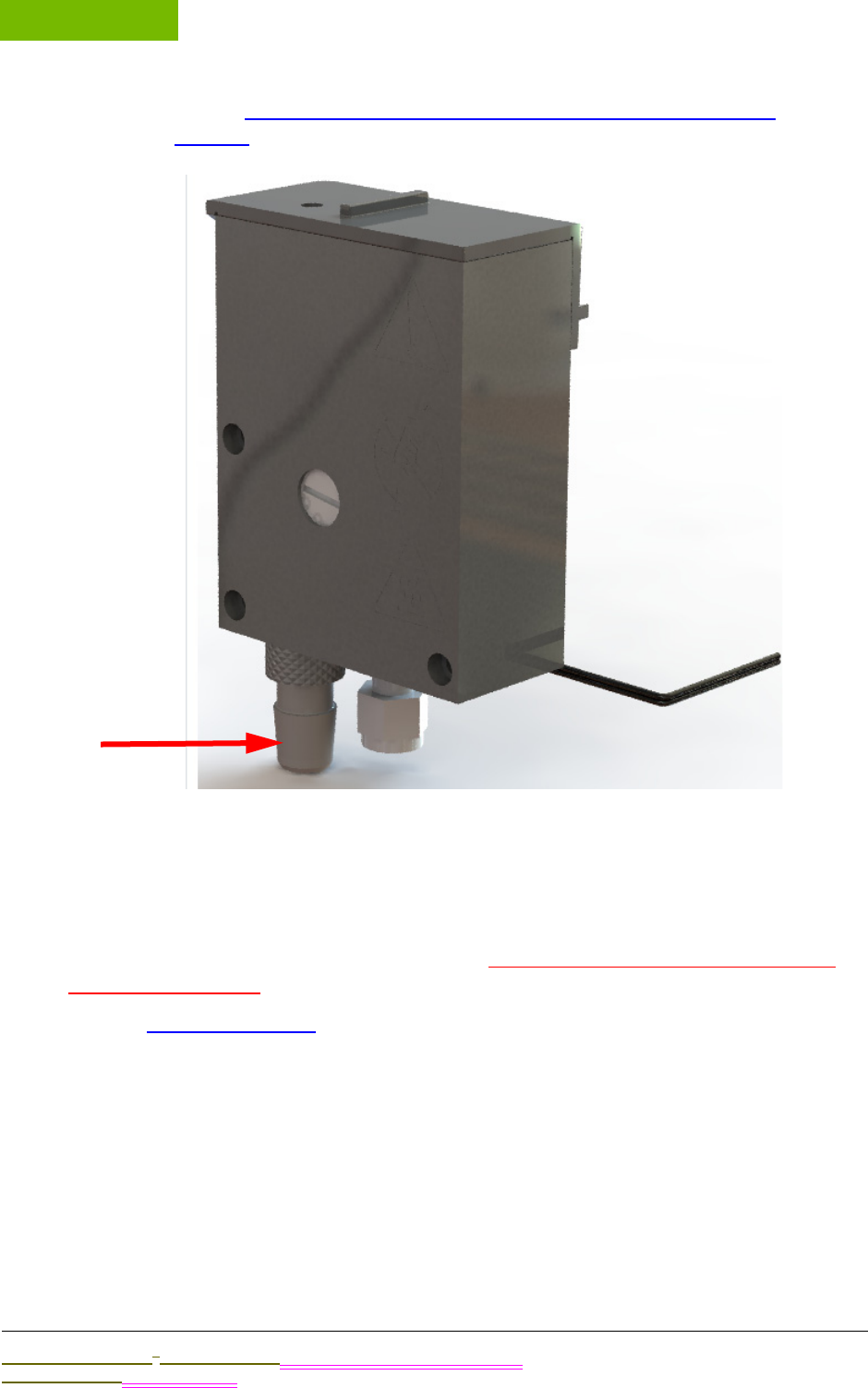
INSTALLATION
Chapter 4
Sievers M9 and M9e TOC AnalyzersSievers M5310 C TOC Analyzer Operation and Maintenance Manual
DLM 77000-01 DLM 77100-01 EN Rev. A GE Analytical Instruments © 2014
94 of 211
section,“Step 9: Install the Waste Outlet (Laboratory Model)” on
page 97, to install the waste outlet.
Figure 27: iOS Waste Outlet Fitting — On-Line and Portable TOC Analyzers
To connect the inlet tubing to the iOS
You will need the 1/4” Teflon inlet tubing (with in-line filter) from the Analyzer’s
Accessories Kit. You will also need to provide You will also need to provide 3/4” OD
plastic waste tubing.
Refer to Figure 28: This iOS, as needed, when performing this instruction.
1. Ensure that the power to the Analyzer is Off and disconnected.
2. Verify that the water source is disabled until you have completely installed the
sample inlet system and the Analyzer is ready to begin analysis.
3. Locate the 1/4" Teflon inlet tubing (with the in-line filter) in the Accessories Kit.
4. Pull out the waste fitting from the bottom of the iOS to gain more working room for
this procedure. You may need to twist it slightly to remove it.
.................................
INSTALLATION INSTRUCTIONS
Sievers M9 and M9e TOC AnalyzersSievers M5310 C TOC Analyzer Operation and Maintenance Manual
DLM 77000-01 DLM 77100-01 EN Rev. A GE Analytical Instruments © 2014
95 of 211
5. Connect the inlet tubing into the sample inlet on the iOS System. Using a 9/16"
open-end wrench, secure the nut. Do NOT over-tighten the nut.
6. Replace the waste outlet fitting (you removed in step 4) to the bottom of the iOS.
7. Slide one end of the waste tubing over the waste outlet (barb) fitting, See iOS
Waste Outlet Fitting — On-Line and Portable TOC Analyzers.
8. Position the tubing for a gravity drain of the waste water, collecting the waste in a
glass laboratory container or facility-approved waste or return line.
9. Establish a water flow to the iOS System.
10. Using a flow meter measure the flow rate, and then adjust to between
50-300 mL/min using the flow rate adjustment screw.
NOTE: The flow rate is controlled by a needle valve, which you can
adjust by turning the screw located on the iOS. Turn the screw clockwise
to decrease flow, or counter-clockwise to increase flow. (See Figure 29:
Flow Rate Adjustment Screw.)
Figure 28: This iOS
Warning
Hazardous reagents (ammonium persulfate and phosphoric acid) are
used in the Analyzer. The waste stream from the instrument is acidic and
must be disposed of properly. Consult your federal, state, and local
government regulations.
Graphic placeholder showing
iOS and the waste outlet fitting
and inlet port
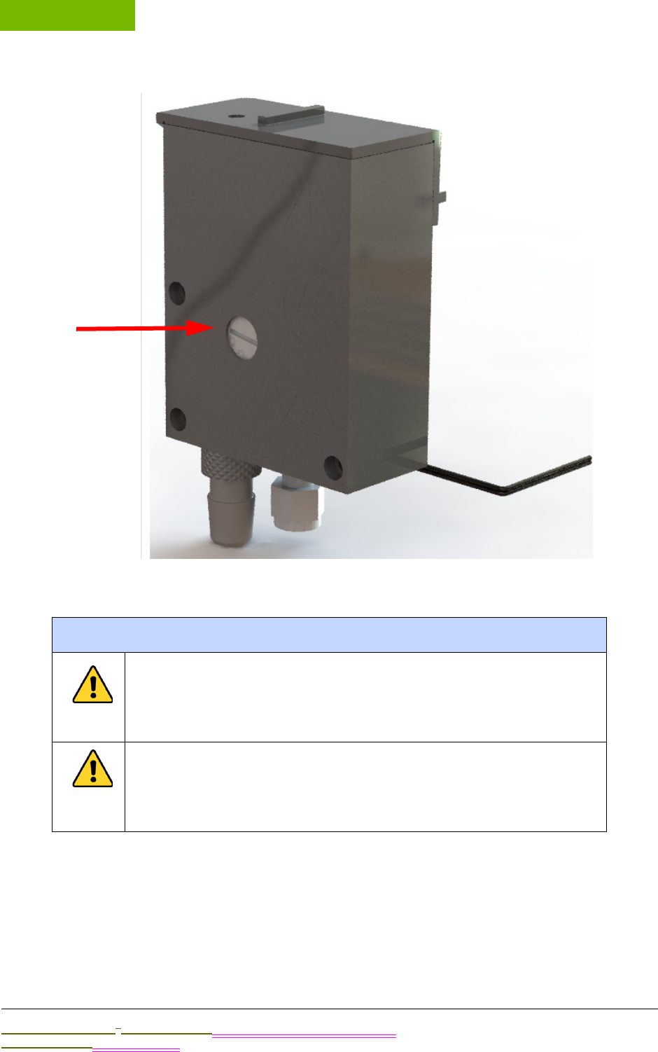
INSTALLATION
Chapter 4
Sievers M9 and M9e TOC AnalyzersSievers M5310 C TOC Analyzer Operation and Maintenance Manual
DLM 77000-01 DLM 77100-01 EN Rev. A GE Analytical Instruments © 2014
96 of 211
Figure 29: Flow Rate Adjustment Screw
Warnings
(On-Line and Portable TOC Analyzers) Operation of the Analyzer
without the in-line filter on the sample inlet line will damage the
Analyzer and void the warranty. To avoid damaging the Analyzer,
install the filter and replace the filter element, as needed.
To avoid false TOC readings and possible damage to the
Analyzer, always make sure the sample is flowing through the
iOS System and the DI water reservoir is filled before starting
analysis.
.................................
INSTALLATION INSTRUCTIONS
Sievers M9 and M9e TOC AnalyzersSievers M5310 C TOC Analyzer Operation and Maintenance Manual
DLM 77000-01 DLM 77100-01 EN Rev. A GE Analytical Instruments © 2014
97 of 211
STEP 9: INSTALL THE WASTE OUTLET (LABORATORY MODEL)
(Laboratory TOC Analyzer Only)
NOTE: If you have an On-Line or Portable TOC Analyzer, IGNORE this
section. Directions for installing the waste outlet are included as part of
the previous section, “Step 8: Connect an On-Line Sample Inlet System”
on page 93.
To install the waste outlet
You will need the 1/8” OD plastic waste tubing with Swagelok® fitting (provided in the
Accessories Kit).
1. Using a 7/16” open-end wrench, disconnect the nut that connects to the Waste
port.
2. Locate the 1/8” OD plastic waste tubing with Swagelok® fitting (provided in the
Accessories Kit).
3. Attach the Swagelok® fitting to the Waste port, and use the 7/16” open-end
wrench to tighten securely.
4. Position the hose for a gravity drain7 of the waste water, collecting the waste in a
glass laboratory container or facility-approved waste or return line.
7. The collecting laboratory container or line should be positioned lower than the iOS waste outlet to
facilitate a gravity-induced flow.
Warnings
Hazardous reagents (ammonium persulfate and phosphoric
acid) are used in the Analyzer. The waste stream from the
instrument is acidic and must be disposed of properly. Consult
your federal, state, and local government regulations.
Graphic Placeholder

INSTALLATION
Chapter 4
Sievers M9 and M9e TOC AnalyzersSievers M5310 C TOC Analyzer Operation and Maintenance Manual
DLM 77000-01 DLM 77100-01 EN Rev. A GE Analytical Instruments © 2014
98 of 211
Figure 30: Waste Outlet Fitting — Laboratory TOC Analyzer
STEP 10: CONFIGURE BASIC ANALYZER SETTINGS
ALL OF THIS SECTION IS A WIP
Before placing your Analyzer into service, you will need to configure various basic settings in
the Analyzer’s firmware using the intuitive touchscreen display (located on the front of the
Analyzer). You will not need to change most of these settings unless you move the Analyzer,
or reconfigure the operational environment.
This section includes how to configure basic analyzer settings, including:
•Powering On and Off the Analyzer
•Enabling Password Protection or DataGuard (Optional)
•Naming the Analyzer Location (Optional)
•Setting the Analyzer Mode and Reagent Flow Rates
•Setting Up the Data History
•Setting Up the Printer (Optional)
•Enabling Turbo
•Exporting and Printing System Constants
•Setting up the Data I/O
Powering On and Off the Analyzer
Each Analyzer model (On-Line, Laboratory, and Portable) has and On/Off power switch8.
However, before pushing the power switch to Off, you MUST first shut down the Analyzer’s
operating system in the firmware in order to avoid the possibility of corrupting the database.
You can then press the power switch to Off to complete the power-down cycle.
When performing maintenance inside the Analyzer, we also recommend that you disconnect
the power cord from the A/C outlet (Laboratory and Portable TOC Analyzers) or shut down the
Mains power supply (On-Line TOC Analyzer).
8. A power On/Off switch is located on the back of the Laboratory and Portable TOC Analyzers and on
the side of the On-Line TOC Analyzer.
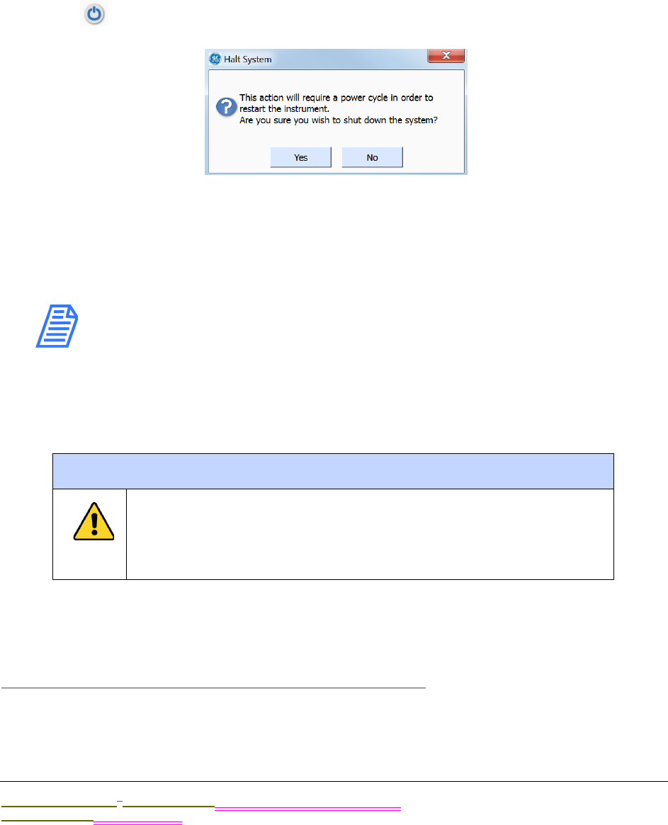
.................................
INSTALLATION INSTRUCTIONS
Sievers M9 and M9e TOC AnalyzersSievers M5310 C TOC Analyzer Operation and Maintenance Manual
DLM 77000-01 DLM 77100-01 EN Rev. A GE Analytical Instruments © 2014
99 of 211
To power On the Analyzer
Press the power switch to On to initiate power in the Analyzer. The firmware screen
illuminates for immediate operation.
To power Off the Analyzer
1. On the Home screen (in the Analyzer’s firmware), press the HALT SYSTEM button
located in the lower-right portion of the screen. The Halt System dialog box
appears.
2. Press YES to confirm that you want to halt the Analyzer’s operating system. The
system will automatically shut down and the screen will de-illuminate (go blank).
3. Locate the power switch on the outside of the Analyzer, and press the power
switch to Off to complete the power-down cycle.
NOTE: The power cycle is NOT complete until you have pressed the
power switch to Off. This ensures that power to ALL circuit boards is
disconnected.
4. If you are planning to perform maintenance inside the Analyzer, disconnect the
Analyzer’s power cord from the A/C outlet (Laboratory and Portable TOC Analyzers)
or shut down the Mains power supply (On-Line TOC Analyzer).
Enabling Password Protection or DataGuard (Optional)
Update this section with firmware development completion
The Sievers 900 Series of TOC Analyzers offers two levels of security, Password Protection and
DataGuard. The Password Protection feature is included with ALL Analyzers and provides a
Warning
In order to avoid the possibility of corrupting the system
database, always FIRST halt system operations from within the
firmware before pushing the Analyzer’s power switch to the Off
position.

INSTALLATION
Chapter 4
Sievers M9 and M9e TOC AnalyzersSievers M5310 C TOC Analyzer Operation and Maintenance Manual
DLM 77000-01 DLM 77100-01 EN Rev. A GE Analytical Instruments © 2014
100 of 211
basic level of security. The DataGuard feature is available as an upgrade and provides
support for the electronic signature regulation 21 CFR Part 11. You can enable one of these
security features, but not both.
This section includes information for enabling Password Protection or DataGuard. Also
included are instructions on how to create a new Administrator account, and how to
deactivate the Default Administrator account. You should perform both of these procedures
during the installation process. For additional information about Password Protection and
DataGuard, refer to Chapter 6.
To enable Password Protection
NOTE: If you are planning to activate DataGuard, there is no need
to additionally activate this Password Protection feature. Instead,
go to next section, “To enable DataGuard.”
1. Select the DataGuard tab.
2. Press the ENABLE PASSWORD button.
3. After Password Protection is enabled, the Analyzer will immediately require you to
log in with the following default Administrator User ID and Password:
•User ID: ADMIN
•Password: GEAI
4. For security purposes, change the default password. Select the DataGuard tab.
5. Press the CHANGE PASSWORD button.
6. Enter the old password (GEAI), and press ENTER.
7. Enter a new password, and press ENTER.
8. Verify the new password, and press ENTER.
9. Record the new password in a secure location. ALL users will be required to enter
this log in information to access the Analyzer’s menus.
To enable DataGuard
1. Insert the USB flash drive containing the DataGuard activation into the Analyzer’s
USB port.
2. Press the MENU button, select the Maintenance tab, and press the ADVANCED
button.
3. Press the ACTIVATE OPTIONS button.
4. Press the OK button and wait for the Analyzer to detect the USB flash drive.
5. Press the ACTIVATE button to enable DataGuard.

.................................
INSTALLATION INSTRUCTIONS
Sievers M9 and M9e TOC AnalyzersSievers M5310 C TOC Analyzer Operation and Maintenance Manual
DLM 77000-01 DLM 77100-01 EN Rev. A GE Analytical Instruments © 2014
101 of 211
6. After DataGuard is enabled, the Analyzer will immediately require you to log in with
the default Administrator User ID and Password. Enter the following:
•User ID: ADMIN
•Password: GEAI
7. Go to the next section and create a new Administrator account.
To create a new Administrator Account (DataGuard Only)
After you activate DataGuard, create a new Administrator Account to ensure Analyzer
security. Step-by-step instructions follow.
1. Press the MENU button and select the DataGuard tab.
2. Press the ADD USER button.
3. Specify a new User ID for the administrator and press the ENTER button.
4. Specify the Password for the administrator User ID and press ENTER.
5. Verify the Password and press ENTER.
6. Press the USER LEVEL button and select Administrator.
7. Press the PASSWORD EXPIRED button and select False.
8. Press the BACK button.
9. Press the LOGOUT button.
10. Go to the next section and delete the default Administrator account.
To deactivate the Default Administrator account
After you have created a new Administrator account, as described in the previous
section, deactivate the Default Administrator account as follows.
1. Press the LOGIN button and enter the new User ID and Password you created in the
previous section.
2. Press the MENU button and select the DataGuard tab.
3. Press the Edit User button.
4. Use the arrow buttons to highlight the Default Administrator account and press
OK.
5. Press the User Status button and select Inactive.
6. Press the Back button to return to the Menu screen.

INSTALLATION
Chapter 4
Sievers M9 and M9e TOC AnalyzersSievers M5310 C TOC Analyzer Operation and Maintenance Manual
DLM 77000-01 DLM 77100-01 EN Rev. A GE Analytical Instruments © 2014
102 of 211
Naming the Analyzer Location (Optional)
To name an Analyzer Location
You can assign a name to the Analyzer, and this name will appear with printed and
exported data. This is useful if you have multiple Analyzers at your facility and want to
readily distinguish data collected from each unit.
1. Select the MAINTENANCE tab.
2. Press the ADVANCED button.
3. Press the ADVANCED SETUP button.
4. Press the LOCATION button.
5. Use the keypad to specify a name for the Analyzer, and then press ENTER.
6. Press the NUMBER button or ALPHA button to toggle between numbers and letters.
7. Press the BACK button to return to the XX.
8. Press the BACK button to return to the Maintenance tab.
Setting the Analyzer Mode and Reagent Flow Rates
NOTE: If you are using your Laboratory or Portable TOC Analyzer
model with a GE Autosampler, do NOT proceed with this section.
The Analyzer mode and reagent flow rates will be controlled by
the DataPro Software.
Set the Analyzer mode for either ON-LINE or GRAB measurements.
By default, the Analyzer uses automatically-calculated reagent flow rates. However, if
you know the specific flow rates you want to use for each reagent, you can manually
set the flow rates according to Table 5 on page 93 and Table 6 on page 93. For more
information on setting flow rates, see “Setting Reagent Flow Rates” on page 89.
To set the Analyzer mode and reagent flow rates
1. On the Home screen, press the SETUP button. The Modify Current Method screen
appears, with the currently selected mode (GRAB or ONLINE) showing in the
Measurement Mode field.
2. Press the Measurement Mode arrow to select another mode:
•ON-LINE— Select to measure TOC continuously from a sample stream.
•GRAB — Select to measure TOC directly from a sample flask or the vial port.
The Method Name field and NEW button appear.

.................................
INSTALLATION INSTRUCTIONS
Sievers M9 and M9e TOC AnalyzersSievers M5310 C TOC Analyzer Operation and Maintenance Manual
DLM 77000-01 DLM 77100-01 EN Rev. A GE Analytical Instruments © 2014
103 of 211
3. Press the keys on the keypad to assign a name to the method you are defining,
and then press OK.
4. For more information on mode selection, see “Setup” on page 88.
5. Press the CONFIGURE button.
6. By default the Analyzer uses the reagent flow rates that are automatically
calculated. If you know the specific flow rates you want to use for each reagent,
you can manually set the flow rates, according to Table 5 on page 93 and Table 6
on page 93. For more information on setting flow rates, see “Setting Reagent Flow
Rates” on page 89.
7. Press the MENU button to exit and save your settings.
Setting Up the Data History
To set up the Data History
Before taking measurements, review the Archive Data setting to ensure that data is
collected in the best way for your environment. By default, data is stored in the
Analyzer’s flash memory, so that all measurements will be retained. If you want to
change the Archive Data setting, follow these steps:
1. Select the DATA tab.
2. Press the SETUP HISTORY button.
3. Confirm that Archive Data is set to On.
NOTE: If DataGuard is enabled, data must either be sent to
storage or the serial port. See xxx for more information.
Activating the Ethernet Connection and Modbus
To activate the Ethernet Connection and Modbus
xxxx
1.
2.

INSTALLATION
Chapter 4
Sievers M9 and M9e TOC AnalyzersSievers M5310 C TOC Analyzer Operation and Maintenance Manual
DLM 77000-01 DLM 77100-01 EN Rev. A GE Analytical Instruments © 2014
104 of 211
Setting Up the Printer (Optional)
To set up the printer
If you installed a printer in Step 6, configure the printer port to match the printer.
1. Select the I/O tab and press the PRINTER button.
2. Press the PRINTER button and select your printer model, either Citizen. Seiko, or
Epson. If you do not have a printer, make sure No Printer is selected.
3. Press the HEADER FREQ. button and select First Page to print a header only on the
first page of output or select All Pages to print a header on all pages of output.
4. Press the PRINT FREQ. button and select how often you would like to print TOC data
information.
Enabling Turbo
To enable Turbo
Brief description of Turbo, optional accessory purchase from ...... Turn the Turbo
indicator on
1. ;lkjasdf
2. a;lkjadf
Exporting and Printing System Constants
Calibration constants, reagent flow rates, and other key parameters are stored in the
Analyzer’s memory. You should export and print the factory settings for future
reference.
To export the settings to a comma-separated text file
1. Select the MAINTENANCE tab.
2. Press the ADVANCED button.
3. Press the USB I/O button. Make sure that the USB flash memory drive from the
Analyzer’s accessory kit is attached to the USB port, then press the SAVE SYSTEM
button. Archive the exported files in a secure location on your computer.
4. Press the BACK button and then press the MENU button.

.................................
INSTALLATION INSTRUCTIONS
Sievers M9 and M9e TOC AnalyzersSievers M5310 C TOC Analyzer Operation and Maintenance Manual
DLM 77000-01 DLM 77100-01 EN Rev. A GE Analytical Instruments © 2014
105 of 211
To print a copy of the settings
If you have a printer attached to the Analyzer, you can print these settings for future
reference by following these steps:
1. Select the tab.
2. Press the ADVANCED button.
3. Press the PRINT CONSTANTS button.
4. Press each of the four buttons, one at a time, to print the different constants.
Setting up the Data I/O
To set up the Data I/O
UPDATE
If you are installing binary input, alarms, or the 4-20 mA output, configure settings for
those features now. Select the I/O tab and configure the appropriate settings. Note
that you may need to consult with your remote operations center to determine some
values. See page 99 through page 103 for details on configuring these settings.
If you installed a 4-20 mA connection or a serial connection, configure the appropriate
settings now. Refer to “Setting Up Analyzer Input and Output” on page 95 for
additional information.
Step 11: Flush and Rinse the Analyzer
Before placing the Analyzer into normal operation, flush the reagents to remove any gas
bubbles that may have formed in the reagent lines. Next, run the Analyzer in On-line mode for
12 hours to thoroughly rinse the sample flow path.
To flush the reagent syringes
If using a flask water supply, you will need the sipper tubing (with Valco fitting) from
the Analyzer’s Accessories Kit. and a 1/4" open-end wrench.
1. Connect to a supply of low-TOC (<50 ppb) DI water in preparation for both this
reagent flush and the Analyzer rinse (described in the next section, To rinse the
sample flow path on page 107).
Connect to one of the following supplies of low TOC (<50 ppb) DI water:
•A continuously flowing on-line stream — No additional setup is required if you
connected an inlet line from a continuous low TOC (<50 ppb) DI water source in
Step 8: Connect an On-Line Sample Inlet System. Proceed to step 5.

INSTALLATION
Chapter 4
Sievers M9 and M9e TOC AnalyzersSievers M5310 C TOC Analyzer Operation and Maintenance Manual
DLM 77000-01 DLM 77100-01 EN Rev. A GE Analytical Instruments © 2014
106 of 211
•A large flask (1000-2000 mL) (On-Line and Portable TOC Analyzers Only) —
Bypass the iOS system by removing the stainless steel tubing that connects the
iOS to the Analyzer. Then, attach a sipper tube to the Inlet port located on the
back of the Analyzer. Proceed to step 2.
•A large flask (1000-2000 mL) (Laboratory TOC Analyzer Only) — Attach a sipper
tube to the Inlet port located on the back of the Analyzer. Proceed to step 3.
2. Use a 1/4" open-end wrench to loosen the Valco nut that connects the stainless
steel tubing from the IOS System to the sample Inlet port.
Carefully pull the stainless steel tubing out of the sample Inlet port. See Figure 34:
Stainless Steel Tubing — Connecting the Analyzer and iOS on page 110.
3. Insert the sipper tube’s Valco fitting into the sample Inlet port, and then tighten the
Valco nut until it is finger-tight. Using a 1/4” open-end wrench, tighten the nut an
additional 1/8 turn.
4. Place the other end of the sipper tube into a large flask containing 1000-2000 mL
of low TOC (<50 ppb) DI water.
5. Verify that the Analyzer is powered On.
6. If you have an ICR, verify that the ICR is configured to On (see the Analyzer’s Setup
screen).
7. On the Maintenance screen, select the Advanced tab.
8. Press FLUSH. The Flush screen appears.
9. Press the Number of Times to Move the Syringe field, and select a number from
1-20. (The default value is 3).
10. Press Flush. The Analyzer begins the syringe flush process and reports the time
remaining on the screen.
When the syringe flush concludes, xxxxx.
11. Halt the system within the firmware (Home screen) and turn the power switch to
Off.
12. Visually inspect inside the Analyzer for any leaks, especially around the DI water
reservoir. If a leak is detected, make sure all fittings are tight and secure.
13. Continue to the next section, “To rinse the sample flow path.”
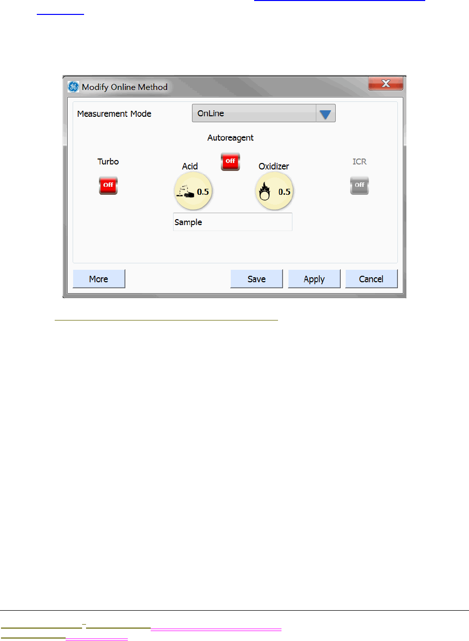
.................................
INSTALLATION INSTRUCTIONS
Sievers M9 and M9e TOC AnalyzersSievers M5310 C TOC Analyzer Operation and Maintenance Manual
DLM 77000-01 DLM 77100-01 EN Rev. A GE Analytical Instruments © 2014
107 of 211
To rinse the sample flow path
Before you begin, ensure that you have connected to a supply of low TOC (<50 ppb) DI
water, as described in the previous section, “To flush the reagent syringes” on
page 105.
Create a Rinse Method
1. On the HOME screen, press SETUP to display the Modify Method dialog box.
Replace this screenshot.
2. Select Online in the Measurement Mode field.
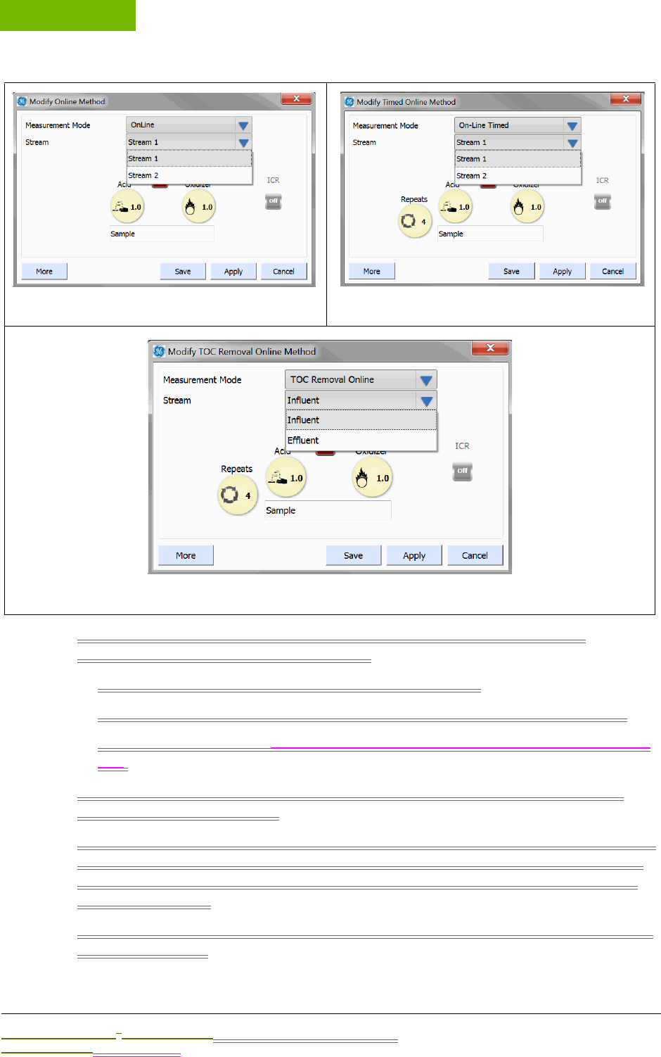
INSTALLATION
Chapter 4
Sievers M9 and M9e TOC AnalyzersSievers M5310 C TOC Analyzer Operation and Maintenance Manual
DLM 77000-01 DLM 77100-01 EN Rev. A GE Analytical Instruments © 2014
108 of 211
3. Select one of the following in the MEASUREMENT MODE field to display the
corresponding Modify Method dialog box:
•Online — (Figure 31: Modify Online Method Dialog Box)
•Online Timed — (Figure 33: Modify TOC Removal Online Method Dialog Box)
•TOC Removal Online — (Figure 33: Modify TOC Removal Online Method Dialog
Box)
4. If you selected Online or Online Timed in the previous step, select Stream 1 or
Stream 2 in the STREAM field.
To set the measurement cycle (hh:mm) for Online Timed measurements, go to the
Configuration screen, select the System Setup tab, and press ONLINE SETUP. After
you have set the measurement cycle, return to the Modify TOC Removal Online
Method Dialog Box
5. If you selected TOC Removal Online in the previous step, select Influent or Effluent
in the STREAM field.
Figure 31: Modify Online Method Dialog Box Figure 32: Modify Timed Online Method Dialog Box
Figure 33: Modify TOC Removal Online Method Dialog Box

.................................
INSTALLATION INSTRUCTIONS
Sievers M9 and M9e TOC AnalyzersSievers M5310 C TOC Analyzer Operation and Maintenance Manual
DLM 77000-01 DLM 77100-01 EN Rev. A GE Analytical Instruments © 2014
109 of 211
6. To assign/name Influent or Effluent to a specific stream (Stream 1 or Stream 2), go
to the Configuration screen, select the System Setup tab, and press ONLINE SETUP.
7. Press the STREAM NAME field to display the alpha/numeric keypad. Use the keypad
to enter RINSE, and then press OK.
8. Set the Autoreagent indicators to Off.
9. Press each of the following to display a numeric keypad. Use the keypad to enter 0,
and then press OK.
•ACID
•OXIDIZER
10. Press FLUSH to display a numeric keypad. Use the keypad to enter 720. (This value =
60 min X 12 hours.) Press OK.
11. If your Analyzer has an ICR, set the indicator to Off.
12. If you have purchased the Turbo mode configuration, set the TURBO indicator to
Off.
NOTE: Turbo (a product option available from
GE Analytical Instruments) must be installed and enabled before
the Turbo feature is active on the screen. See “To enable Turbo” on
page 104.
13. Press SAVE. This will overwrite the previous Online method file, and erase any
earlier settings.
14. Press APPLY to return to the HOME screen.
Run an Analysis with the New RINSE Method
1. On the HOME screen, press RUN to begin the rinse. The rinse will run for 12
hours.
2. After the rinse completes, the XX appears.
3. Press XXX to close the Summary screen.
4. Do one of the following:
•If you used a continuously flowing on-line stream — No additional steps are
required. Your Analyzer is ready to begin normal sample analyses.
•If you used a large flask (1000-2000 mL) (On-Line and Portable TOC Analyzers
Only) — Reconnect the iOS system by reattaching the stainless steel tubing that
connects the iOS to the Analyzer. Remove the sipper tube from the Inlet port
located on the back of the Analyzer, and connect the inlet tubing from your on-
line water source. (You can also choose not connect an on-line water source.)

INSTALLATION
Chapter 4
Sievers M9 and M9e TOC AnalyzersSievers M5310 C TOC Analyzer Operation and Maintenance Manual
DLM 77000-01 DLM 77100-01 EN Rev. A GE Analytical Instruments © 2014
110 of 211
Your On-Line or Portable TOC Analyzer is ready to begin normal sample
analyses.
•If you used a large flask (1000-2000 mL) (Laboratory TOC Analyzer Only) —
Remove the sipper tube from the Inlet port located on the back of the Analyzer.
Your Laboratory TOC Analyzer is ready to begin normal sample analyses.
Graphic placeholder
Figure 34: Stainless Steel Tubing — Connecting the Analyzer and iOS
How to Install Valco Tube Fittings
Evaluate where to place this section after determining which tubing the user will need to
install a Valco fitting, and how many section reference the tubing installation.
1. Locate the sipper, sample, or other tubing? from the Analyzer’s Accessories Kit? .
2. Slide the Valco fitting and the ferrule onto the sample tubing. Leave at least
several millimeters of tubing extend beyond the tip of the ferrule. Make sure the
orientation of nut to ferrule is as show in Figure on page 110Figure 35: Nut and
Ferrule Orientation
3. Push the tubing into the Sample Inlet port on the Analyzer until there is resistance,
and then hold the tubing in place.
4. Still holding the tubing in place, slide the ferrule and nut down the tubing into the
sample Inlet port and tighten the nut until it is finger-tight.
5. Use a 1/4" open-end wrench to then turn the nut 1/4 turn past finger-tight. Do not
over-tighten the fitting.
NOTE: It is only necessary to turn the nut 1/4 past finger-tight to
swage the nut on initial installation. During future operations, only
turn the nut 1/8 turn past finger-tight.
Graphic placeholder
Figure 35: Nut and Ferrule Orientation
STEP 12: INSTALL A GE AUTOSAMPLER
Laboratory and Portable TOC Analyzers
If you are planning to use a GE Autosampler with your Analyzer, you can install it now. Refer to
the GE Autosampler Installation Guide for complete installation instructions.


5
..............................................
Sievers M9 and M9e TOC AnalyzersSievers M5310 C TOC Analyzer Operation and Maintenance Manual
DLM 77000-01 DLM 77100-01 EN Rev. A GE Analytical Instruments © 2014
113 of 211
5
OPERATION
OVERVIEW
THIS CHAPTER IS NOT READY FOR REVIEW AT THIS TIME. Need to update with recent firmware
changes/research.
WIP notes only Add this info: to text in correct places:
MISCELLANEOUS NOTES FOR SECTIONS TO ADD
To sample using the iOS
With the Analyzer configured in an on-line configuration (see xxx), you can conveniently
switch between on-line sampling and discrete sampling using the iOS. You do NOT need to
change the configuration to analyze a standard with the iOS System. The Analyzer
automatically shuts off on-line water flow when it detects that the iOS door is closed and/or a
vial is inserted into the iOS.
The iOS is simple to use. Simply stop analysis, slide the iOS System door open to the left, wait
30 seconds for sample to drain from the iOS System, and then insert a 40-mL vial containing
sample? or the standard. Also, refer to xx for additional calibrating and operation safety x xx
when operating the iOS for the first time.
Additionally (one time procedure or each time?), after you establish water flow to the iOS
System, you should adjust the flow rate so that flow exiting the waste line is between 30 - 300
mL/min. The flow rate is controlled by a needle valve, which is adjusted by the screw on the
iOS. Turn the screw clockwise to decrease flow, and turn the screw counter-clockwise to
increase flow. How do you measure the flow rate? separate stand-alone flow meter?

OPERATION
Chapter 5
Sievers M9 and M9e TOC AnalyzersSievers M5310 C TOC Analyzer Operation and Maintenance Manual
DLM 77000-01 DLM 77100-01 EN EN Rev. A GE Analytical Instruments © 2014
114 of 211
Always stop analysis before opening the iOS System door to avoid generating erroneous
measurement data. If the flow sensor is On, opening the iOS System door while analysis is
taking place causes the flow sensor to activate and halt analysis. If the flow sensor is Off,
opening the iOS System door while analysis is taking place results in air being drawn into the
Analyzer.
Warning
The iOS System contains sharp needles designed to pierce the septa of sample vials. Do not
put fingers or inappropriate materials into the iOS System.
XXXXXSievers M9 and M9e TOC Analyzers Operation and Maintenance Manual
SAMPLING USING A SIPPER TUBE
The Analyzer Configured for Use with a Sipper Tube (Grab Mode)
The Vial Port
The vial port provides a convenient sample inlet for analyzing standards in 40-mL vials. You
do not need to change the sample figuration to analyze a standard in the vial port. Simply
stop analysis, slide the vial port door open, and insert the 40-mL vial containing the standard.
Always stop analysis before opening the vial port door to avoid generating erroneous
measurements. Opening the door while analysis is taking place results in air being drawn into
the Analyzer.
Warning
The vial port contains two sharp needles designed to pierce the septa of sample vials. Do not
put fingers or inappropriate materials into the vial port.
GRAB SAMPLE INSTALLATION — FROM A SAMPLING CONTAINER
Move to operations chapter
To run grab samples from a container, collect the sample using a sipper tube connected to
Analyzer’s Inlet port. If your Analyzer has an iOS system, you must bypass the iOS in the grab
sample setup process, as described in the following instruction.
To collect grab samples from a container
1. If your Analyzer does NOT have an iOS, go directly to step 4
2. Locate the 1/16" OD stainless steel tubing that runs from the iOS System to the
bulkhead fitting labeled Sample Inlet.
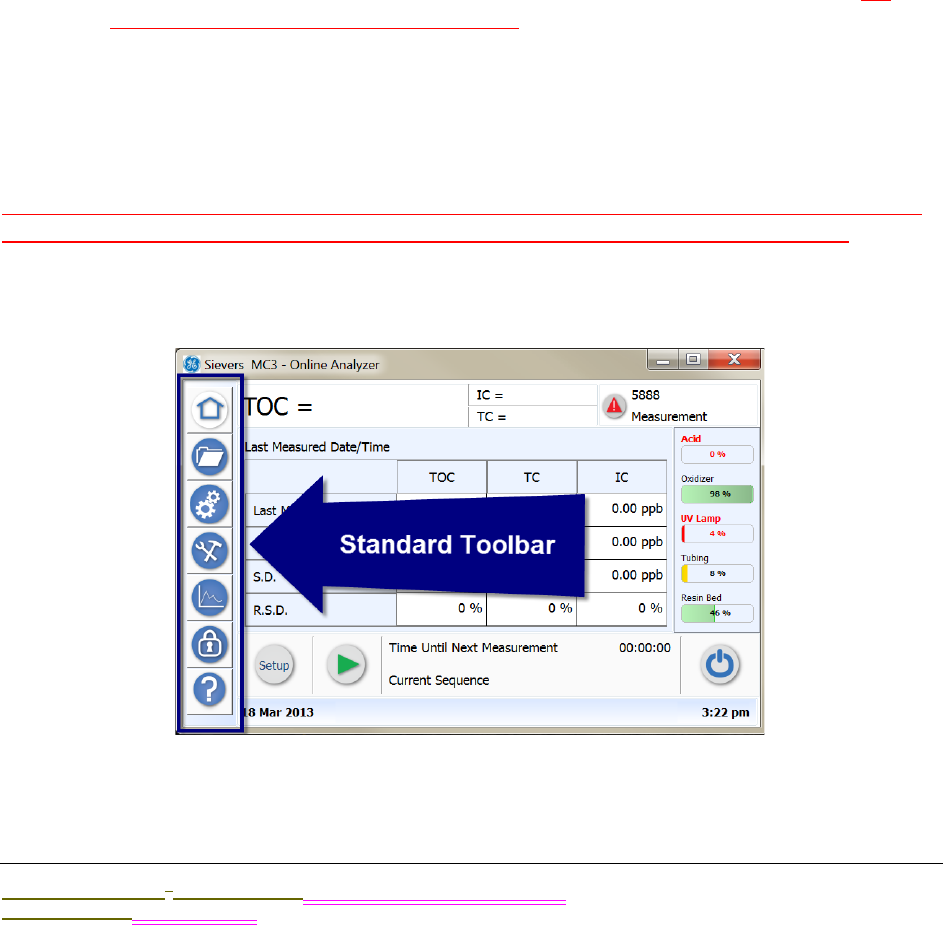
.................................
INTRODUCTION TO THE ANALYZER SCREENS
Sievers M9 and M9e TOC AnalyzersSievers M5310 C TOC Analyzer Operation and Maintenance Manual
DLM 77000-01 DLM 77100-01 EN EN Rev. A GE Analytical Instruments © 2014
115 of 211
3. Use a 1/4" open-end wrench to loosen the Valco® fitting at the Sample Inlet port.
Carefully rotate the tubing away from the Analyzer so that tubing is clear of the
inlet.
4. Locate the sipper tube (1/16" Teflon tubing with Valco nut) that is provided in the
Accessories Kit.
5. Insert the Valco fitting into the Sample Inlet port, located on the left side of the
Analyzer.
6. Tighten the Valco fitting until it is finger-tight, and then tighten an additional 1/8
turn using a 1/4" open-end wrench.
7. Place the open end of the sipper tube into the sample container, making sure that
the end of the tubing is immersed in the sample.
8. Place parafilm over the container opening. Do NOT push the sipper tube through
the parafilm or it may clog the tube.
9. Operate the Analyzer in Grab mode. For more information on Grab mode, see
“Setting the Analyzer Mode” on page 88.
INTRODUCTION TO THE ANALYZER SCREENS
EDITING NOTE: Screen title does NOT show on Analyzer screen. Also, there are no arrows by
tabs, as all tabs are sized smaller. Screen background color may be slightly different.
The Analyzer's touchscreen display changes according to the screen you select from the
Standard toolbar (located on left side of the screen).
Simply press one of the following buttons on the Analyzer’s Standard Toolbar to display the
related screen.
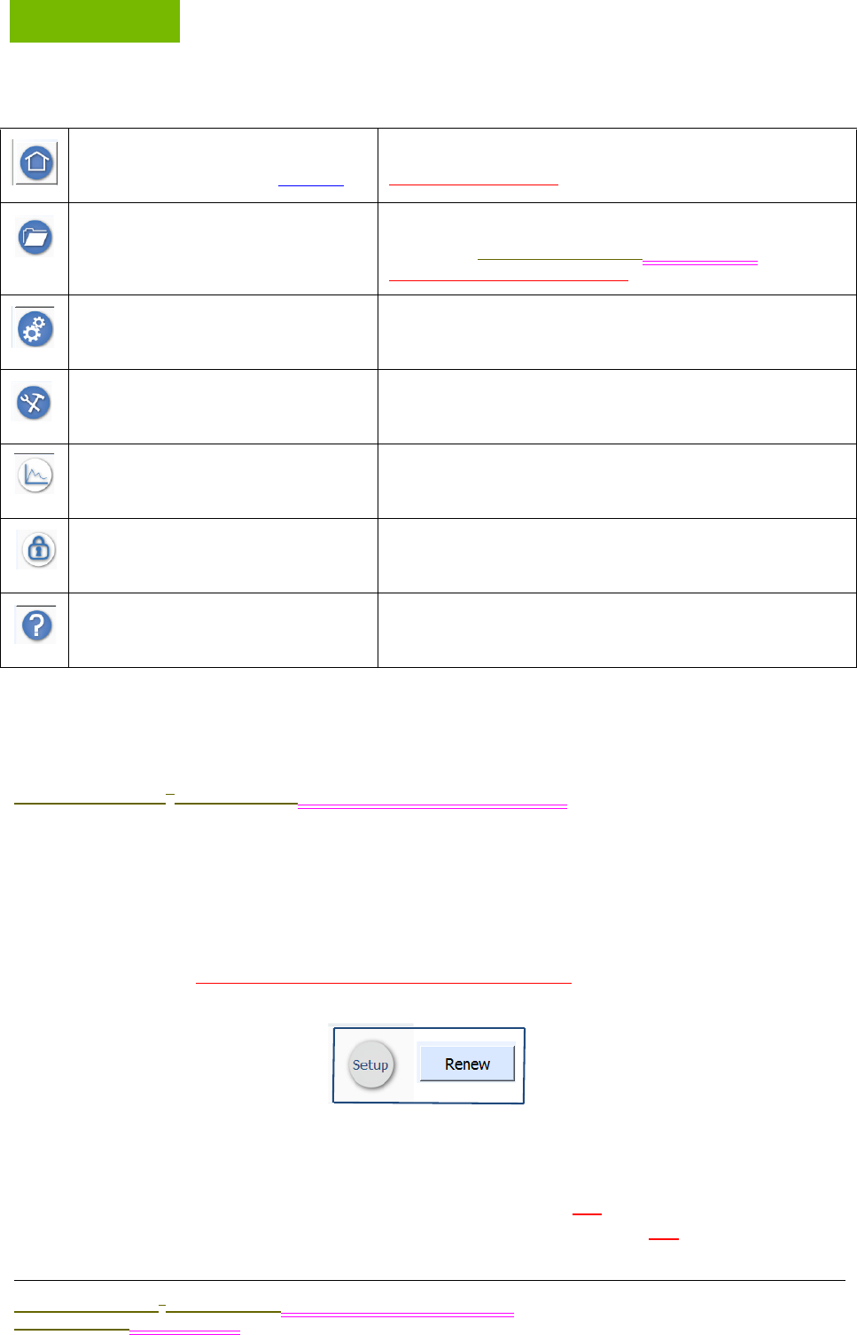
OPERATION
Chapter 5
Sievers M9 and M9e TOC AnalyzersSievers M5310 C TOC Analyzer Operation and Maintenance Manual
DLM 77000-01 DLM 77100-01 EN EN Rev. A GE Analytical Instruments © 2014
116 of 211
Navigating in the Screens
You will find using the Analyzer Display screens is easy and intuitive. When first using the
Sievers M9 or M9e TOC AnalyzerSievers M5310 C TOC Analyzer, you may find the following
navigational information helpful.
BUTTONS
Screens include various buttons that may either initiate an action (such as, to start sampling)
or display a related screen or dialog box. The button appearance may vary as shown in the
following examples. Buttons may change with xxx selections.....
Seamless Hyperlinks
The Home screen also contains some seamless (hidden) hyperlink functionality in the
consumables level and warning and error alert areas. You can tap a consumables level
indicator to display the Consumables tab on the Maintenance screen, or tap the warnings and
HOME
(For more screen details, go to page 118.)
Indicators for DataGuard enabled and Password Protection.
Research these further
PROTOCOLS System Protocols and User Defined Methods
Calibration, Pharmacopoeia Tests,Municipal Test, Validation
Refer to page X for more details.
CONFIGURATION Single Point Calibration, Sample Conductivity, Multi-Point
Calibration, TOC Autozero, TC / IC Cell Conductivity Autozero
MAINTENANCE
DATA VIEW
SECURITY /DATAGUARD
HELP
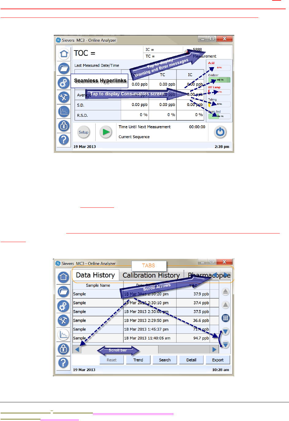
.................................
INTRODUCTION TO THE ANALYZER SCREENS
Sievers M9 and M9e TOC AnalyzersSievers M5310 C TOC Analyzer Operation and Maintenance Manual
DLM 77000-01 DLM 77100-01 EN EN Rev. A GE Analytical Instruments © 2014
117 of 211
error alert area to display a separate dialog box with message details and functionality. To
exit screen, you MUST either click OK (intuitively I want to exit instead. What happens when I
click OK? It clears or does it remain for me to go back to? would I need to as a user?
TABS AND SCROLLING
Several screens have individual tabs that you can press to display additional related screens.
Left and right arrows appear if there are additional tabs extending beyond the screen view. To
see these additional tabs, flick press? the right scroll arrow. You can than use the right and left
scroll arrows to navigate to the various tabs, as needed. Some screens may also include scroll
arrows (left, right, up, down) to enable viewing additional data that extends beyond the
border of the screen. On Analyzer screen, there are no arrows by tabs, as all tabs are sized
smaller.
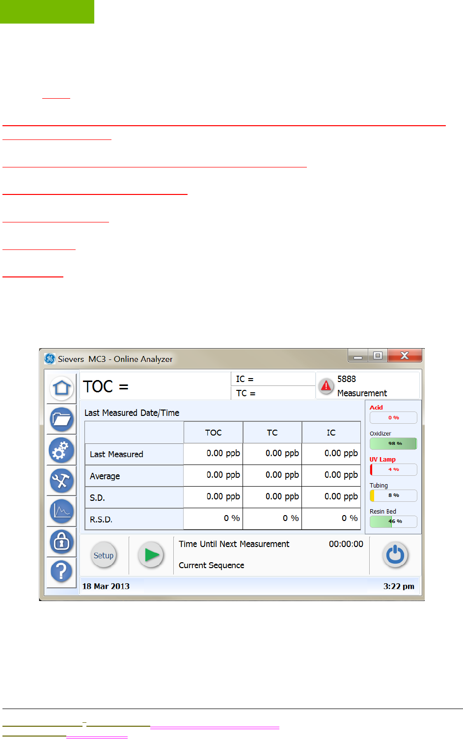
OPERATION
Chapter 5
Sievers M9 and M9e TOC AnalyzersSievers M5310 C TOC Analyzer Operation and Maintenance Manual
DLM 77000-01 DLM 77100-01 EN EN Rev. A GE Analytical Instruments © 2014
118 of 211
Field Selections
Tap the down arrow to display field options for selection....
create one or more setup configurations measurement mode Grab or On-Line Name and
save a method Select
set number of repeats and rejects set acid and oxidizer levels
More fast flush and normal flush time
Autoreagent on or off
Turbo on or off
ICR on or off
USING THE HOME SCREEN
Use this screen to set up and run sample analyses of TOC measurements. The Analyzer
reports the sampling status and data on this screen during the process. Any warnings or
errors appear on the top right of the screen, which you can tap to view the specific
message(s) and access to the Diagnosis screen. You can also monitor remaining
consumables’ levels from the Home screen.
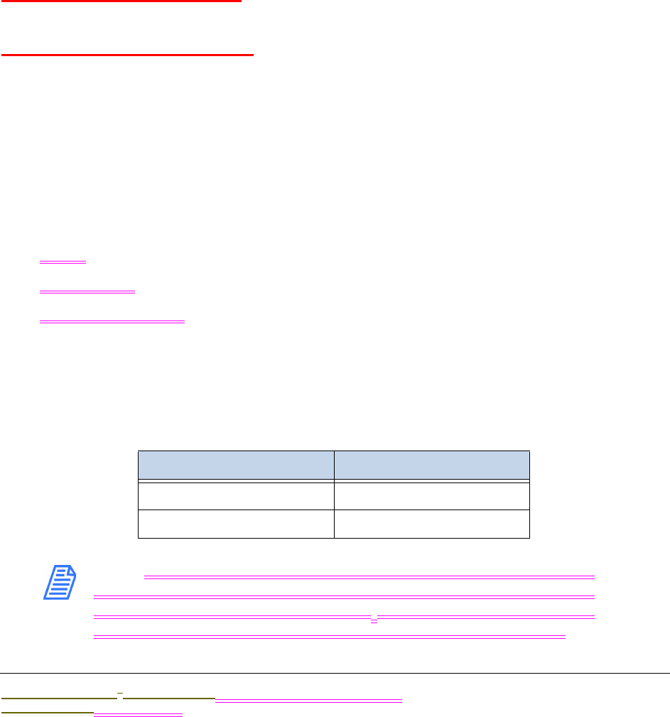
.................................
USING THE HOME SCREEN
Sievers M9 and M9e TOC AnalyzersSievers M5310 C TOC Analyzer Operation and Maintenance Manual
DLM 77000-01 DLM 77100-01 EN EN Rev. A GE Analytical Instruments © 2014
119 of 211
•Create sample setup configurations
•Run a sample (view any errors).
•Quick view consumables
•Shut down the instrument
Creating Sample Setup Configurations OVERVIEW
Before you begin, useful overview information about xxxxxxxxxxxuseful in creating sample
setup configurations....
UNDERSTANDING ANALYSIS TIME
FAST FLUSH AND NORMAL FLUSH .
SELECTING A MEASUREMENT MODE
Grab
TOC Removal Grab
On-Line....
•Online
•Online Timed
•TOC Removal Online
SETTING REAGENT FLOW RATES
xxxx
NOTE: For municipal applications, we recommend decreasing the
acid flow rate to 1.0 µL/min for municipal water application with an
alkalinity of less than 100 mg/L CaCO3. Always check the pH of your
undiluted water to ensure it is below ph3, but not less than pH2.
TABLE 5: RECOMMENDED ACID FLOW RATES

OPERATION
Chapter 5
Sievers M9 and M9e TOC AnalyzersSievers M5310 C TOC Analyzer Operation and Maintenance Manual
DLM 77000-01 DLM 77100-01 EN EN Rev. A GE Analytical Instruments © 2014
120 of 211
DO we need to change the tables to reflect municipal water application flow rates only for
the M5310 C manual?
USING AN ICR
xxxx
RUNNING SAMPLES IN TURBO MODE
Autoreagent
Manual
FAST FLUSH NORMAL FLUSH
;lkjasdf
To create or change a Sampling Method? — GRAB MODE
Create and save to use .....include overview grab, TOC removal grab, online, online
timed, xxxx
TABLE 6: RECOMMENDED OXIDIZER FLOW RATES
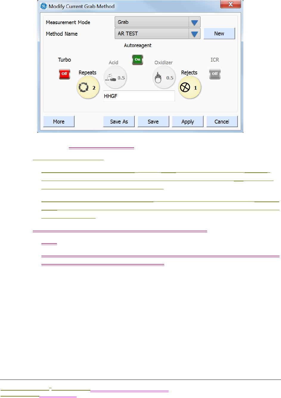
.................................
USING THE HOME SCREEN
Sievers M9 and M9e TOC AnalyzersSievers M5310 C TOC Analyzer Operation and Maintenance Manual
DLM 77000-01 DLM 77100-01 EN EN Rev. A GE Analytical Instruments © 2014
121 of 211
1. On the Home screen, press SETUP to display the Modify Method dialog box.
2. Select Grab or TOC Removal Grab in the Measurement Mode field.
3. Do one of the following:
•To create a new configuration — Press NEW to display the numeric keypad.
Use the keypad to enter a name for the method, and then press OK. The new
name appears in the Method name field.
•To change an existing configuration — Select the configuration in the METHOD
NAME field. Enter new values, as needed, in steps X to X, and then go to step X to
save the changes.
4. Select one of the following in the Measurement Mode field:
•Grab
•TOC Removal Grab — With this measurement mode selection, also select either
Influent or Effluent in the Vial Name field.
5. Do the following:
•Press REPEATS to display the numeric keypad. Use the keypad to enter a value,
and then press OK.
•Press REJECTS to display the numeric keypad. Use the keypad to enter a value,
and then press OK.
6. To use the Autoreagent feature (RECOMMENDED), set the AUTOREAGENT indicator to
On. The Oxidizer and Acid indicators are now inactive.
The Analyzer will automatically calculate and implement the proper reagent flow
rates.

OPERATION
Chapter 5
Sievers M9 and M9e TOC AnalyzersSievers M5310 C TOC Analyzer Operation and Maintenance Manual
DLM 77000-01 DLM 77100-01 EN EN Rev. A GE Analytical Instruments © 2014
122 of 211
NOTE: Refer to Setting Reagent Flow Rates for more information on
using the Autoreagent feature.
Can the user still modify the Autoreagent rate? RICHARD CHECKING 3/21 Kurt/Paul checking
4/10(Set in manual first and then autoreagent?
7. To manually set the flow rate of the reagents, do the following:
•Verify that the Autoreagent indicator is set to Off to ensure that the ACID and
OXIDIZER buttons are in an active state.
•Press ACID to display the numeric keypad. Use the keypad to enter a value, and
then press OK.
•Press OXIDIZER to display the numeric keypad. Use the keypad to enter a value,
and then press OK.
NOTE: For recommended reagent rates, refer to Recommended Acid
Flow Rates and Recommended Oxidizer Flow Rates on page
page 120.
8. To set a new value (the default value is XX) for a fast or normal flush time, press
MORE to display the More Method Configuration dialog box. Do the following:
•Press inside the Fast Flush Time field to display the numeric keypad. Enter a
value (in minutes), and then press OK.
•Press inside the Normal Flush Time field to display the numeric keypad. Enter a
value (in minutes), and then press OK.
9. To operate the Analyzer with an ICR, set the ICR indicator to On. Otherwise. if your
instrument does NOT have an ICR (or you want to bypass the ICR), go to the next
step.
10. To operate the Analyzer in Turbo mode, set the TURBO indicator to On. Otherwise. if
your instrument does NOT have Turbo (or you want to run in regular mode), go to
the next step.
For information on Turbo mode, see “Running Samples in Turbo Mode” on
page 120.
11. Do one of the following:
•To save as the method name showing in the Method Name field — Press SAVE.
This will overwrite any previous settings saved to this name.
•To save as the method with a NEW name — Press SAVE AS to display the Enter
Protocol Name dialog box. Use the alpha/numeric keypad to enter a unique
name, and then press OK.
ICR BUTTON DOES NOT WORK
Where do I schedule (are we having) autoreagent adjustments in On-Line Mode?
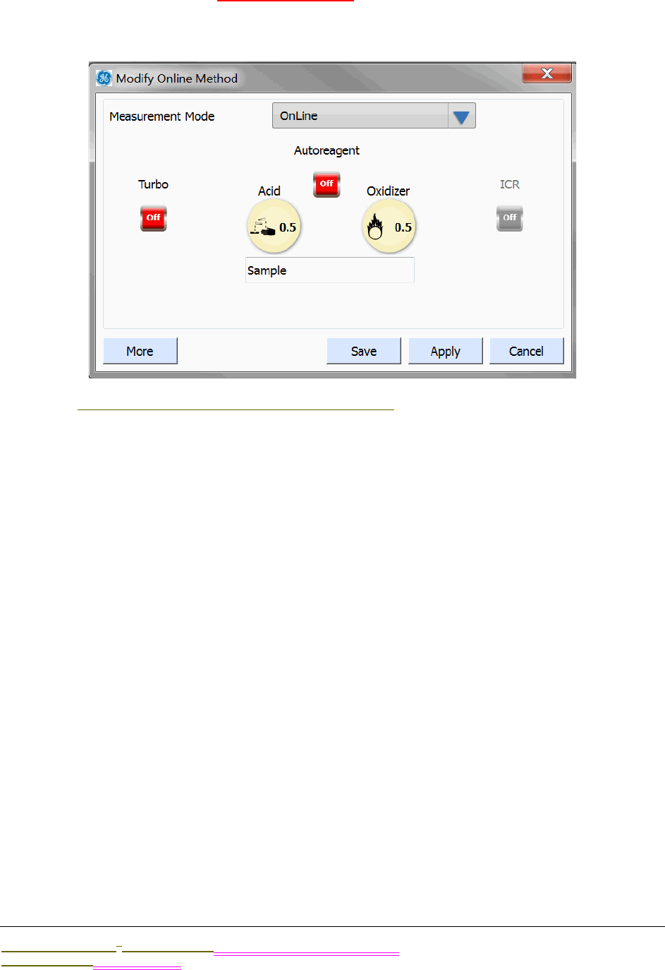
.................................
USING THE HOME SCREEN
Sievers M9 and M9e TOC AnalyzersSievers M5310 C TOC Analyzer Operation and Maintenance Manual
DLM 77000-01 DLM 77100-01 EN EN Rev. A GE Analytical Instruments © 2014
123 of 211
To create or change a Sampling Method? — ONLINE MODE
1. On the HOME screen, press SETUP to display the Modify Method dialog box.
2. Select Online in the Measurement Mode field.

OPERATION
Chapter 5
Sievers M9 and M9e TOC AnalyzersSievers M5310 C TOC Analyzer Operation and Maintenance Manual
DLM 77000-01 DLM 77100-01 EN EN Rev. A GE Analytical Instruments © 2014
124 of 211
3. Select one of the following in the MEASUREMENT MODE field to display the
corresponding Modify Method dialog box:
•Online — (Figure 36: Modify Online Method Dialog Box)
•Online Timed — (Figure 38: Modify TOC Removal Online Method Dialog Box)
•TOC Removal Online — (Figure 38: Modify TOC Removal Online Method Dialog
Box)
4. If you selected Online or Online Timed in the previous step, select Stream 1 or
Stream 2 in the STREAM field.
To set the measurement cycle (hh:mm) for Online Timed measurements, go to the
Configuration screen, select the System Setup tab, and press ONLINE SETUP. After
you have set the measurement cycle, return to the Modify TOC Removal Online
Method Dialog Box
5. If you selected TOC Removal Online in the previous step, select Influent or Effluent
in the STREAM field.
Figure 36: Modify Online Method Dialog Box Figure 37: Modify Timed Online Method Dialog Box
Figure 38: Modify TOC Removal Online Method Dialog Box

.................................
USING THE HOME SCREEN
Sievers M9 and M9e TOC AnalyzersSievers M5310 C TOC Analyzer Operation and Maintenance Manual
DLM 77000-01 DLM 77100-01 EN EN Rev. A GE Analytical Instruments © 2014
125 of 211
To assign/name Influent or Effluent to a specific stream (Stream 1 or Stream 2), go
to the Configuration screen, select the System Setup tab, and press ONLINE SETUP.
6. Press inside the SAMPLE NAME field (located under the ACID and OXIDIZER buttons) to
display the alpha/numeric keypad. Use the keypad to enter a name (such as XYZ
Building Waste Line) for the Online method, and then press OK.
7. To use the Autoreagent feature (RECOMMENDED), set the AUTOREAGENT indicator to
On. The Oxidizer and Acid indicators are now inactive.
The Analyzer will automatically calculate and implement the proper reagent flow
rates.
NOTE: Refer to Setting Reagent Flow Rates for more information on
using the Autoreagent feature.
Can the user still modify the Autoreagent rate? RICHARD CHECKING 3/21(Set in manual first
and then autoreagent?
8. To manually set the flow rate of the reagents, do the following:
•Verify that the Autoreagent indicator is set to Off to ensure that the ACID and
OXIDIZER buttons are in an active state.
•Press ACID to display the numeric keypad. Use the keypad to enter a value, and
then press OK.
•Press OXIDIZER to display the numeric keypad. Use the keypad to enter a value,
and then press OK.
NOTE: For recommended reagent rates, refer to Recommended Acid
Flow Rates and Recommended Oxidizer Flow Rates on page
page 120.
9. To set a value for a fast or normal flush time, press MORE to display the More
Method Configuration dialog box. Do the following:
•Press inside the Fast Flush Time field to display the numeric keypad. Enter a
value (in minutes), and then press OK.
•Press inside the Normal Flush Time field to display the numeric keypad. Enter a
value (in minutes), and then press OK.
10. To operate the Analyzer with an ICR, set the ICR indicator to On. Otherwise. if your
instrument does NOT have an ICR (or you want to bypass the ICR), go to the next
step.
11. To operate the Analyzer in Turbo mode, set the TURBO indicator to On. Otherwise. if
your instrument does NOT have Turbo (or you want to run in regular mode), go to
the next step.
OPERATION
Chapter 5
Sievers M9 and M9e TOC AnalyzersSievers M5310 C TOC Analyzer Operation and Maintenance Manual
DLM 77000-01 DLM 77100-01 EN EN Rev. A GE Analytical Instruments © 2014
126 of 211
NOTE: Turbo (a product option available from
GE Analytical Instruments) must be installed and enabled before
the Turbo feature is active on the screen. See “To enable Turbo” on
page 104.
12. Press SAVE. This will overwrite the previous Online method file, and erase any
earlier settings.
Running a sample
WIP overview.....Add note All setup and then run a sample?take TOC measurement
To run a sample
When taking a TOC measurement of your sample, you can assign a unique sample
name.
1. On the Home screen, press SETUP to display the Modify . . . Method dialog box.
2. Select the measurement mode to use (Grab or TOC Removal Grab or On-Line) in the
Measurement Mode field.
3. Select the method to use in the METHOD NAME field.
4. (Optional) Assign a sample name. Press inside the Sample Name field to display
the numeric keypad. Use the keypad to enter a name for the sample, and then
press OK. The new name appears in the Sample Name field.
5. Click APPLY to use this method and return to the Home screen.

.................................
USING THE HOME SCREEN
Sievers M9 and M9e TOC AnalyzersSievers M5310 C TOC Analyzer Operation and Maintenance Manual
DLM 77000-01 DLM 77100-01 EN EN Rev. A GE Analytical Instruments © 2014
127 of 211
6. Press RUN to begin the sampling. The sampling progress and measurement data
appears on the screen in real time.
NOTE: For additional information on measurement status and data,
refer to “Reviewing the Home Screen” on page 127.
Reviewing the Home Screen
You can also see an alert for active Warnings and Errors and percent indicators of remaining
consumables’ levels.
and start and stop sample analyses.
, open related messages (and go to Diagnostics screen.
Data from your last measured sample stays
A table containing data from the last measured sample appears on the Home screen to
provides TOC (IC and TC) data along with mean standard deviation (S.D.) and relative standard
deviation (RSD) of the sample.
percent indicators of remaining consumables’ levels,
Table Last Measurement
TOC (IC and TC)
Last measured
Average
S.D.
R.S.D.
To the right, Consumables Life visual status
Acid
Oxidizer
UV Lamp

OPERATION
Chapter 5
Sievers M9 and M9e TOC AnalyzersSievers M5310 C TOC Analyzer Operation and Maintenance Manual
DLM 77000-01 DLM 77100-01 EN EN Rev. A GE Analytical Instruments © 2014
128 of 211
Tubing
Resin Bed
Setup button
(Arrow) Start Analysis
Time Until Next Measurement
Current Sequence
Shut Down button
Lower current date and time
VIEWING CONSUMABLES LEVELS
Quick view consumables
SHUTTING DOWN THE INSTRUMENT
WIP If they just power off, there is a danger of corrupting database. We are running an OS
just like your computer. You don’t want to just power cycle.
USING THE PROTOCOLS SCREEN
Overview and then cross-reference to Chapter 5 Password Protection and DataGuard
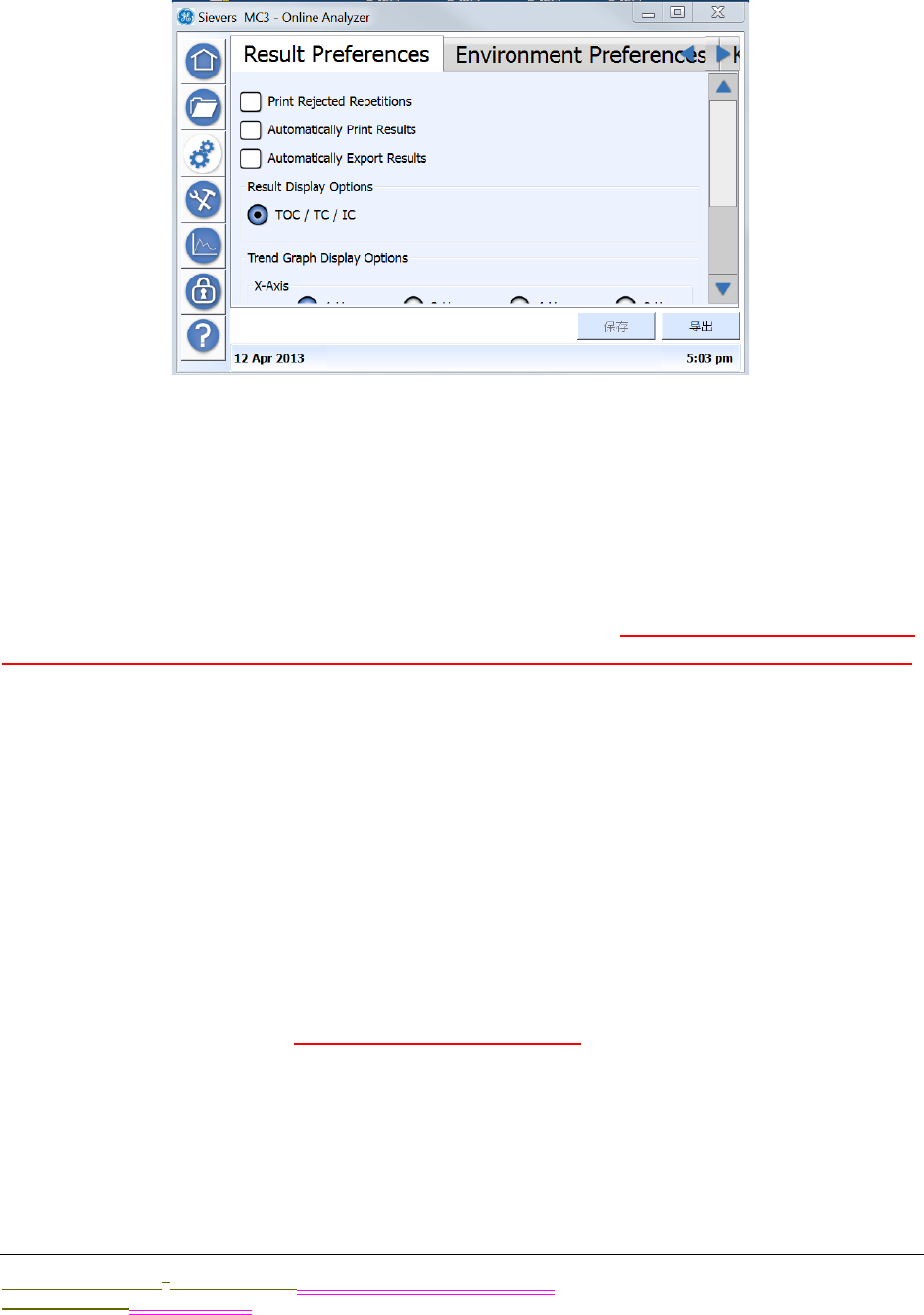
.................................
USING THE CONFIGURATION SCREEN
Sievers M9 and M9e TOC AnalyzersSievers M5310 C TOC Analyzer Operation and Maintenance Manual
DLM 77000-01 DLM 77100-01 EN EN Rev. A GE Analytical Instruments © 2014
129 of 211
USING THE CONFIGURATION SCREEN
Overview information
;lkjasdf
System Settings (Constants) Export
You can save system settings for any tab on the screen XXXXX Suggest before and after?(Do
you have to export for each tab? Or, does it automatically export constants from every tab?)
An EXPORT button is available on each tab on the Configuration window. XXXX
To export system settings (constants)
1. On the Configuration screen, select the appropriate Configuration window tab,
2. Verify the options selected, and press SAVE if you make any changes.
3. To export the saved configuration settings, do one of the following:
•To export to a USB memory device — Insert the USB memory device into one of
the Analyzer’s Host USB ports, and then press EXPORT. The settings will be
exported to the USB memory device.
•To export through an Ethernet connection — Press EXPORT. The settings will be
exported to the designated MODBUS register via Ethernet. The data can then
be accessed from your company’s SCADA system or a third-party data
acquisition software.
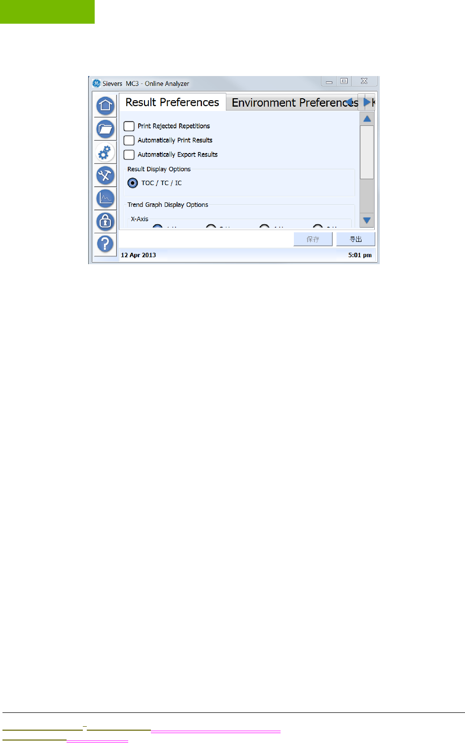
OPERATION
Chapter 5
Sievers M9 and M9e TOC AnalyzersSievers M5310 C TOC Analyzer Operation and Maintenance Manual
DLM 77000-01 DLM 77100-01 EN EN Rev. A GE Analytical Instruments © 2014
130 of 211
The Result Preferences Tab
Use this procedure to set your preferences for printing and exporting results, as well as to
define settings for the trend graph. The trend graph appears on the Home screen, when the
ON-LINE mode is selected as the Measurement Mode on the Modify Current Online Method
dialog box.
To set result preferences
1. On the Configuration screen, select the Result Preferences tab.
2. Select any or all of the following options to set your preferences for printing and
exporting results:
•Print Rejected Repetitions
•Automatically Print Results
•Automatically Export Results
3. Select one of the following result display options for the type of data to graph:
•TOC/IC/TC
•TOC/TCond
•TOC/rCond/Temp
•rCond/Temp/tCond (This option shows measurements for conductivity only,
and data is indicated on the X-axis.)
4. Select one of the following time ranges for the data on the X-Axis:
•1 Hour
•2 Hours
•4 Hours
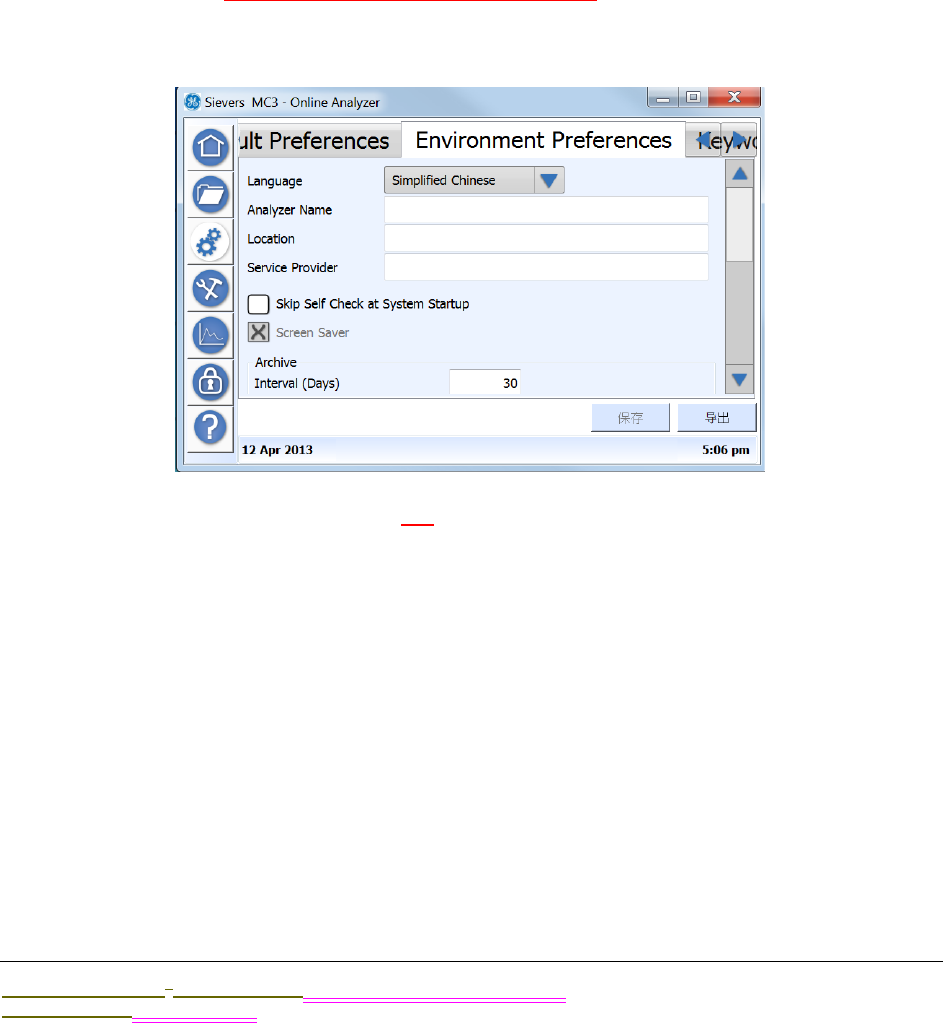
.................................
USING THE CONFIGURATION SCREEN
Sievers M9 and M9e TOC AnalyzersSievers M5310 C TOC Analyzer Operation and Maintenance Manual
DLM 77000-01 DLM 77100-01 EN EN Rev. A GE Analytical Instruments © 2014
131 of 211
•8 Hours
•1 Day
•2 Days
•1 Week
5. Select one of the following options for the TOC range on the Y-Axis:
•Auto — Select to have the Analyzer automatically calculates the appropriate
TOC range.
•Manual — Select to activate the Min and Max fields, and then enter a specific
value in ppb units in each field.
6. Press SAVE. Just for the tab or all tabs on screen?
The Environment Preferences Tab
Use this tab to set the language xxx. You can assign a name to the Analyzer that
appears on printed and exported data. a name, location, and service provider for the
Analyzer. This feature is particularly useful if you have multiple Analyzers at your
facility and want to easily distinguish data collected from each instrument.
To set the language
To change to a new language other than the default language configured at the
factory, perform the following steps.
1. On the Configuration screen, select the Environment Preferences tab.
1. Select one of the preferred languages for the Analyzer:
•English (1st position in language option list)
•Simplified Chinese (2nd position in language option list)

OPERATION
Chapter 5
Sievers M9 and M9e TOC AnalyzersSievers M5310 C TOC Analyzer Operation and Maintenance Manual
DLM 77000-01 DLM 77100-01 EN EN Rev. A GE Analytical Instruments © 2014
132 of 211
•Japanese (3rd position in language option list)
2. Press SAVE (1st button on the lower-right of screen).
3. You must restart the Analyzer for this change to take effect. On the Home screen,
press the SHUT DOWN button and then restart the Instrument.
To set environment preferences
1. On the Configuration screen, select the Environment Preferences tab.
2. (Optional) To set the Analyzer Name and Location (and Service Provider? what is
meant here?), Press inside each of the following fields to display the numeric
keypad. Use the keypad to enter a name, and then press OK. The new name
appears in the corresponding field.
•Analyzer Name
•Location
•Service Provider
3. Select or de-select the following display preferences:
•Skip Self Check at System Startup
•Screensaver
4. Set the timing values for archiving and backing up data. Press inside each of the
following fields to display the numeric keypad. Use the keypad to enter the value
(in days), and then press OK. The new number of days appears in the
corresponding field.
•Archive Interval (Days)
•Data Age (Days)
•Backup Interval (Days)
5. Select one of the following for the time formats to display:
•01:42:58 (am/pm)
•13:42:58 (24 Hour)
6. Select one of the following date formats to display:
•16 Jan 2012 (Text Based)
•01/16/2012 (Month First)
•16/01/2012 (Day First)
•2012/01/16 (Year First)
7. Press SAVE.
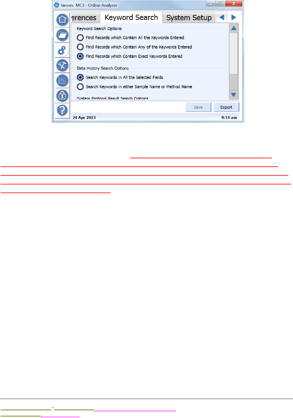
.................................
USING THE CONFIGURATION SCREEN
Sievers M9 and M9e TOC AnalyzersSievers M5310 C TOC Analyzer Operation and Maintenance Manual
DLM 77000-01 DLM 77100-01 EN EN Rev. A GE Analytical Instruments © 2014
133 of 211
The Keyword Search Tab
Select parameter options for the keyword search and that is accessed through the Data
History tab on the Configuration screen. Select whether to search ALL selected fields, or only
the Sample Name or Method Name field. (Need help understanding the intent of these
options, as the search seems to work the same for each option??) Is the system protocol
result search for searching results in all of the following? Validation History, Pharmacopoeia
History, Calibration History, and Data History ....whether to search ALL selected fields, or only
the Protocol Name and Vial Name?
To set keyword search options
1. On the Configuration screen, select the Keyword Search tab.
2. Select one of the following keyword search options:
•Find Records which contain All the Keywords Entered
•Find Records which contain Any of the Keywords Entered
•Find Records which contain Exact Keywords Entered
3. Select one of the following data history search options:
•Search keywords in All the Selected Fields
•Search keywords in either Sample Name or Method Name
4. Select one of the following system protocol result search options:
•Search Keywords in All the Selected Fields
•Search Keywords in either Protocol Name or Vial Name
5. Press SAVE.
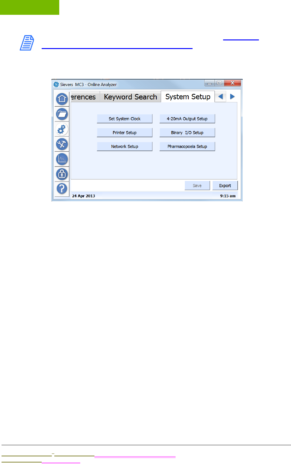
OPERATION
Chapter 5
Sievers M9 and M9e TOC AnalyzersSievers M5310 C TOC Analyzer Operation and Maintenance Manual
DLM 77000-01 DLM 77100-01 EN EN Rev. A GE Analytical Instruments © 2014
134 of 211
NOTE: For more information on MODBUS, refer to “Using the
Ethernet Connection and Modbus” on page 149.
The System Setup Tab
XXX
•Set System Clock
•Printer Setup
•Network Setup
•4-20mA Output Setup
•Binary I/O Setup
•Phamacopoeia Setup
SETTING THE SYSTEM CLOCK
;lkjasdf;lkjasdf
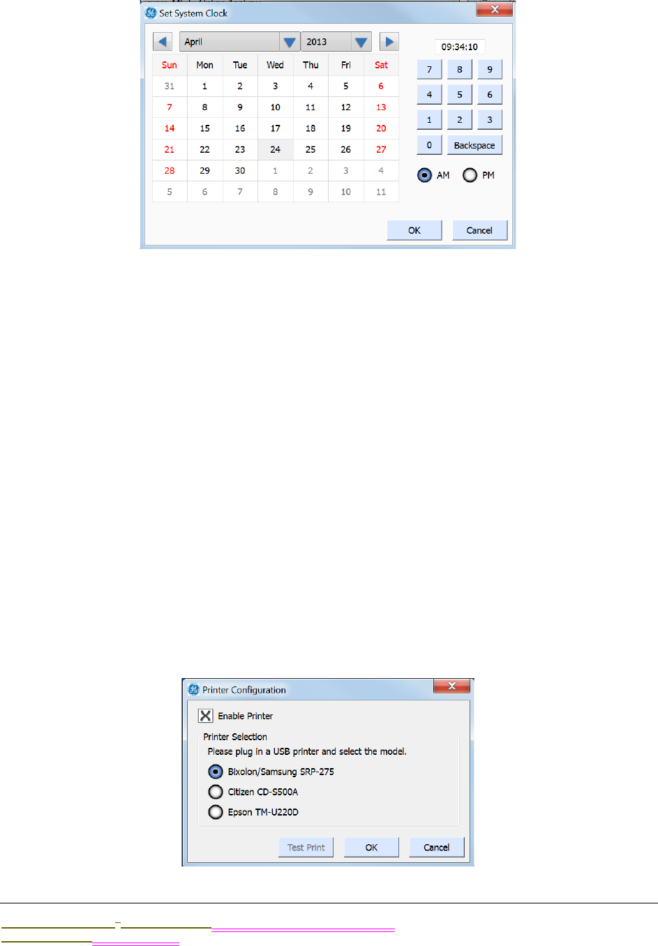
.................................
USING THE CONFIGURATION SCREEN
Sievers M9 and M9e TOC AnalyzersSievers M5310 C TOC Analyzer Operation and Maintenance Manual
DLM 77000-01 DLM 77100-01 EN EN Rev. A GE Analytical Instruments © 2014
135 of 211
To set the system clock
1. On the Configuration screen, select the System Setup tab.
2. Press SET SYSTEM CLOCK to display the Set System clock dialog box.
3. Using the calendar, set today’s current date.
4. Using the numeric keypad to the right, set the current time and select either the
AM or PM option.
5. Press OK to accept the settings and return to the System Setup tab.
6. Press another button to change the related setting.
CONFIGURING A PRINTER
;lkjasdf
To configure a printer connection (optional)
Connect the printer as described in xxxx
1. On the Configuration screen, select the System Setup tab.
2. Press PRINTER SETUP to display the Printer Configuration dialog box.
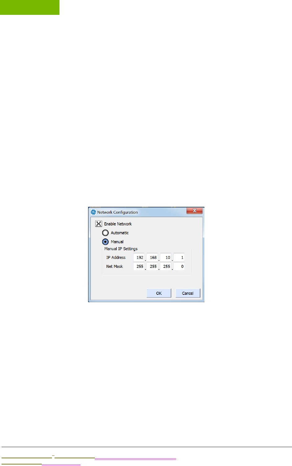
OPERATION
Chapter 5
Sievers M9 and M9e TOC AnalyzersSievers M5310 C TOC Analyzer Operation and Maintenance Manual
DLM 77000-01 DLM 77100-01 EN EN Rev. A GE Analytical Instruments © 2014
136 of 211
3. Select ENABLE PRINTER.
4. Select one of the following printer models:
•Bixolon/Samsung SRP-275
•Citizen CD-S500A
•Epson TM-U220D
5. Press OK to accept the settings and return to the System Setup tab.
CONFIGURING THE NETWORK
lkjasdf;lkjasdf
To configure the network connection
Connect the xxx as described in xxxx. Work with your IT department to xxxx .
1. On the CONFIGURATION screen, select the System Setup tab.
2. Press NETWORK SETUP to display the Network Configuration dialog box.
3. Select ENABLE NETWORK.
4. To use a dynamic IP address, select Automatic, and then OK. Otherwise, to the
next step.
5. To use a fixed IP address, select MANUAL.
6. Enter the IP and net mask addresses. Press inside each field to display the numeric
keypad. Use the keypad to enter the appropriate number, and then press OK. The
new number appears in the individual field.
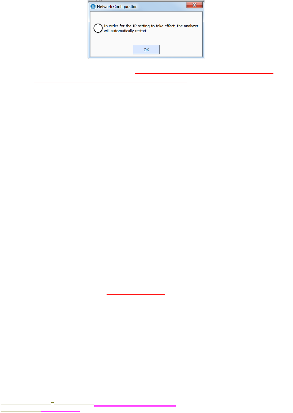
.................................
USING THE CONFIGURATION SCREEN
Sievers M9 and M9e TOC AnalyzersSievers M5310 C TOC Analyzer Operation and Maintenance Manual
DLM 77000-01 DLM 77100-01 EN EN Rev. A GE Analytical Instruments © 2014
137 of 211
7. After you have entered the full IP Address and Net Mask addresses, press OK. A
confirmation message appears.
8. Press OK to confirm the restart. The Analyzer automatically shuts down and
restarts in order to implement the new IP setting.
CONFIGURING 4-20MA OUTPUT
;lkjasdf
To configure the 4-20mA output (optional)
Connect the xxx as described in xxxx.
1. On the Configuration screen, select the System Setup tab.
2. Press 4-20MA OUTPUT SETUP to display the 4-20mA Output Configuration dialog box.
3. Select 4-20MA OUTPUT. (development WIP)
4. Press OK to accept the settings and return to the System Setup tab.
CONFIGURING BINARY I/O INPUT
;lkjer
To configure the binary I/O input (optional)
Connect the xxx as described in xxxx.
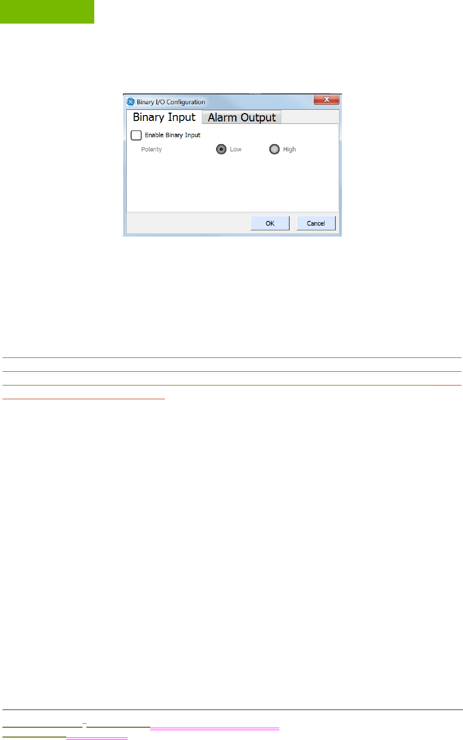
OPERATION
Chapter 5
Sievers M9 and M9e TOC AnalyzersSievers M5310 C TOC Analyzer Operation and Maintenance Manual
DLM 77000-01 DLM 77100-01 EN EN Rev. A GE Analytical Instruments © 2014
138 of 211
1. On the Configuration screen, select the System Setup tab.
2. Press BINARY I/O SETUP to display the Binary I/O Configuration dialog box.
3. Select ENABLE BINARY INPUT.
4. Select either the LOW or HIGH Polarity option,
5. Press OK to accept the settings and return to the System Setup tab.
PHARMACOPOEIA OVERVIEW
Because pharmacopoeia TOC and conductivity (consider changing terminology) monographs
diverge, the Analyzer allows you to specify which pharmacopoeia monograph is applicable to
your environment. (You can also use the Analyzer without selecting a pharmacopoeia.) (Does
one of these apply as a default?).Pharmacopoeia monographs shape the criteria for
Conductivity limits and pass/fail results, as well as temperature and conductivity guidelines.
Pass/Fail Reporting
The TOC Analyzer will report a Pharmacopoeia “Pass” result, if all of the selected
pharmacopoeia tests pass identified criteria and limits. The TOC Analyzer will report a
Pharmacopoeia “Failure” result, if any of the selected tests fail. Conductivity and TOC tests
can be independently tested with the alarms, an alarm can be set for each of TOC Limit,
Cond Limit, or Limits. Limits will trigger if any of the TOC or conductivity tests fail. TOC Limit
only if any of the TOC tests fail, and Cond Limit only if any of the conductivity tests fail.
Pharmacopoeia Options
You can select any combination (or none) of the following Pharmacopoeia options:
USP WFI/PW: The Analyzer meets the test requirements for the United States
Pharmacopoeia (USP) monographs; USP<643> Total Organic Carbon and USP<645>
Conductivity. The water passes the USP<643> TOC test if its measured TOC (ru) is not more
than the Limit Response, (rs – rw). The water sample passes the Stage 1 conductivity test if
the measured conductivity is not greater than the table value (at the first temperature in
the chart that is not greater than the measured water temperature).

.................................
USING THE CONFIGURATION SCREEN
Sievers M9 and M9e TOC AnalyzersSievers M5310 C TOC Analyzer Operation and Maintenance Manual
DLM 77000-01 DLM 77100-01 EN EN Rev. A GE Analytical Instruments © 2014
139 of 211
EP WFI/HPW: The Analyzer meets the test requirements of the following European
Pharmacopoeia (EP) monographs; EP (2.2.44) Total Organic Carbon in Water for
Pharmaceutical Use and the Conductivity Requirements of the EP monographs “Water for
Injections” (WFI) and “Water, Highly Purified” (HPW). The TOC test passes if the measured
TOC of the pharmaceutical water sample is not less than the lower of the Limit Response
or 500 ppbC (per the requirements of the EP WFI and HPW monographs). The Stage 1
conductivity test passes if the measured non-temperature compensated conductivity
value is not greater that the conductivity value in the table for WFI at the next lower
temperature (in the table), than the measured temperature of the water (Stage 1 test in the
WFI or HPW monographs).
CP WFI: The Analyzer meets the test requirements of the following Chinese
Pharmacopoeia (CP) monographs; CP TOC Measurement in Pharmaceutical Water-
Appendix VIII R for Water for Injection and CP Conductivity- Appendix VIII S for Water for
Injection. The TOC test passes if the sample of WFI has a measured TOC value not greater
than (rs – rw) or 0.50 g/L. The conductivity test passes Step 1 if the measured non-
temperature compensated conductivity is not greater than the table conductivity value at
the next lower temperature value in the table that is not greater than the measured
temperature.
IP WFI: The Analyzer meets the test requirements of the India Pharmacopoeia (IP)
monographs for Water for Injection: IP 2.4.30 Total Organic Carbon in Water and IP 2.4.9
Conductivity for Water for Injections in Bulk. The TOC test is passed if the measured TOC of
the sample (rt) is not greater than
(rs – rw) or not more than 0.5 mg/L. The Stage 1 conductivity test is passed if the non-
temperature corrected conductivity is not greater than the table value for WFI at the next
lowest temperature value in the table that is not greater than the measured water
temperature.
JP TOC: The Analyzer meets the test requirements of the Japanese Pharmacopoeia (JP)
monographs; JP<2.59> Total Organic Carbon for Water for Injection and Purified Water.
The test passes if the measured Water for Injection or Purified Water sample TOC value is
not greater than 0.50 mg/L.
EP PW: The Analyzer meets the testing requirements of the following European
Pharmacopoeia (EP) monograph for Purified Water (PW); EP<2.2.44 Total Organic Carbon
in Water for Pharmaceutical Use and the Conductivity Requirements of the EP
monographs “Water, Purified”. The TOC test passes if the measured TOC of the
pharmaceutical water sample is not less than the lower of the Limit Response or 500 ppbC
(per the requirements of the EP PW monograph). The conductivity test passes if the
measured conductivity (not the temperature compensated conductivity) is not greater that
the value in the “Temperature and Conductivity requirements table” (in the EP PW
monograph) at the measured temperature of the water. For temperatures not listed in the
table, he maximal permitted conductivity is calculated by interpolation between the next
lower and next higher temperature data points in the table.
CP PW: The Analyzer meets the testing requirements for the following Chinese
Pharmacopoeia (CP) monographs; CP TOC Measurement in Pharmaceutical Water-

OPERATION
Chapter 5
Sievers M9 and M9e TOC AnalyzersSievers M5310 C TOC Analyzer Operation and Maintenance Manual
DLM 77000-01 DLM 77100-01 EN EN Rev. A GE Analytical Instruments © 2014
140 of 211
Appendix VIII R for Water for Injection and CP Conductivity- Appendix VIII S for Water for
Injection. The TOC test passes if the sample of WFI has a measured TOC value not greater
than (rs – rw) or 0.50 g/L. The conductivity test passes if the measured conductivity (not the
temperature compensated conductivity) is not greater that the value in the “Temperature
and Conductivity requirements table” in the CP Conductivity- Appendix VIII S (for purified
water) monograph at the measured temperature of the water. For temperatures not listed
in the table, he maximal permitted conductivity is calculated by linear interpolation
between the next lower and next higher temperature data points in the table.
IP PW: The Analyzer meets the testing requirements of the India Pharmacopoeia (IP)
monographs for Water for Injection: IP<2.4.30> Total Organic Carbon in Water and IP 2.4.9
and Conductivity IP<2.4.9> for Purified Water. The TOC test is passed if the measured TOC
of the sample (rt) is not greater than (rs – rw) or not more than 0.5 mg/L. The conductivity
test passes Step 1, if the measured non-temperature compensated conductivity is not
greater than the conductivity value in the table for Purified Water at the next lower
temperature value in the table, that is not greater than the measured temperature.
JP COND: The Analyzer meets the testing requirements of the Japanese Pharmacopoeia
(JP) Conductivity <2.51>. The test passes if the temperature corrected conductivity is not
more than 2.1 uS/cm.
SELECTING A PHARMACOPOEIA MONOGRAPH
Because pharmacopoeia TOC and conductivity monographs diverge, the Analyzer
allows you to specify which pharmacopoeia monograph is applicable to your
environment. You can also use the Analyzer without selecting a pharmacopoeia. Refer
to XX for pharmacopoeia descriptions.
To specify the pharmacopoeia (optional)
1. On the Configuration screen, select the System Setup tab.
2. Press PHARMACOPOEIA SETUP to display the Pharmacopoeia Configuration dialog
box.(development WIP)
3. Select one or more of the following pharmacopoeia options (in any combination).
Or, to use the Analyzer without selecting a pharmacopoeia, deselect ALL of the
options.
4. Press OK to accept the settings and return to the System Setup tab.
THE SAVE button is not active? Should it be? When to use it-after each dialog box, tab, other
change?
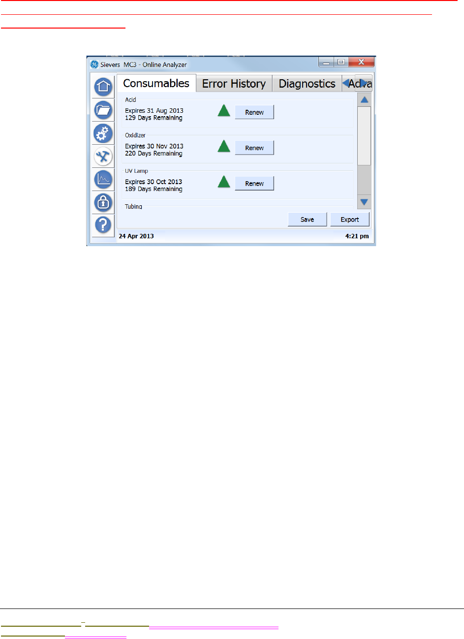
.................................
USING THE MAINTENANCE SCREEN
Sievers M9 and M9e TOC AnalyzersSievers M5310 C TOC Analyzer Operation and Maintenance Manual
DLM 77000-01 DLM 77100-01 EN EN Rev. A GE Analytical Instruments © 2014
141 of 211
USING THE MAINTENANCE SCREEN
Revise this section by summarizing the sections that describe preventative maintenance, as
this is detailed in the Maintenance Chapter. Also move the troubleshooting tasks to the
Troubleshooting Chapter.
Overview
Use this screen in the process of performing the following preventative maintenance tasks:
•Enter and track consumables expiration (Consumables Tab)
•Flush reagent syringes (Advanced Tab)
•Temporarily disable the screen for cleaning (Advanced Tab)
You will also use this Maintenance screen to access the tabs for the following operational
maintenance tasks, as described in other chapters (as listed):
•Error History Tab — Review the list of errors and warnings issued by the Analyzer during
operation of the instrument. Step-by-step instructions, and error/warning descriptions, are
included in Chapter 9, "Troubleshooting."
•Diagnostics Tab — Use this tab to perform diagnostic activities when troubleshooting
operational and analyses issues, Information and instructions are included in Chapter 9,
"Troubleshooting."
•Advanced Tab — Use this tab to upgrade firmware, activate options, back up the database,
back up settings, archive the database, calibrate the touch panel, restore the database,

OPERATION
Chapter 5
Sievers M9 and M9e TOC AnalyzersSievers M5310 C TOC Analyzer Operation and Maintenance Manual
DLM 77000-01 DLM 77100-01 EN EN Rev. A GE Analytical Instruments © 2014
142 of 211
and restore settings. This tab and the related step-by-step instructions are included in
Chapter 5, "Operation."
SETTINGS (CONSTANTS) EXPORT
You can save system settings for any tab on the screen XXXXX Suggest before and after?(Do
you have to export for each tab? Or, does it automatically export constants from every tab?)
An EXPORT button is available on each tab on the Configuration window. XXXX
To export system settings (constants)
1. On the Maintenance screen, select the appropriate Maintenance tab,
2. Verify the options selected, and press SAVE if you make any changes.
3. To export the saved maintenance settings, do one of the following:
•To export to a USB memory device — Insert the USB memory device into one of
the Analyzer’s Host USB ports, and then press EXPORT. The settings will be
exported to the USB memory device.
•To export through an Ethernet connection — Press EXPORT. The settings will be
exported to the designated MODBUS register via Ethernet. The data can then
be accessed from your company’s SCADA system or a third-party data
acquisition software.
The Consumables Tab
You can view the expiration date and number of remaining days for the following
consumables on this tab:
•Acid
•Oxidizer
•UV Lamp
•Tubing
•Resin Bed
A triangle icon appears next to the RENEW button to indicate the severity of the expiration
date: green (adequate time frame) Is there a yellow(?), or red (Expiration nearing). Use this tab
to reset the expiration date after replacing a consumable item.
To renew an expiration date
After replacing the consumables item in the Analyzer.....
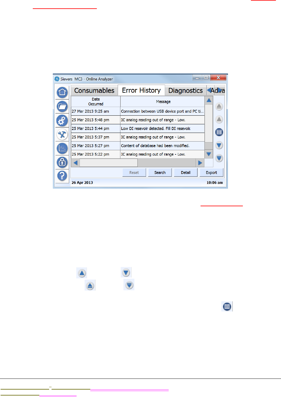
.................................
SETTINGS (CONSTANTS) EXPORT
Sievers M9 and M9e TOC AnalyzersSievers M5310 C TOC Analyzer Operation and Maintenance Manual
DLM 77000-01 DLM 77100-01 EN EN Rev. A GE Analytical Instruments © 2014
143 of 211
1. On the Maintenance screen, select the Consumables tab.
2. Press the RENEW button next to the consumable item you have replaced. (feature
not yet implemented)
3. xxx
4. xxx
5. Press SAVE.
The Error History Tab
You can use this tab to search and view a cumulative list of recent and historical errors and
warnings.
To view error and warning history
1. Use the vertical scrollbar to move through a list of recent messages (listed most
recent to oldest). Or, use one of the following buttons to scroll through the
messages:
•Use the UP and DOWN arrows to skip forward and backward by a page.
•Use the START and END arrows to take you to the most recent or oldest
message (respectively).
2. To search for messages for a specific date, press the CALENDAR icon to display
the Calendar dialog box. Use the navigation arrows (as needed) to locate the date,
and then press the day to view.
The Analyzer automatically returns you to the Validation History tab with any
messages from the selected date displayed.

OPERATION
Chapter 5
Sievers M9 and M9e TOC AnalyzersSievers M5310 C TOC Analyzer Operation and Maintenance Manual
DLM 77000-01 DLM 77100-01 EN EN Rev. A GE Analytical Instruments © 2014
144 of 211
3. To search for messages by a keyword, User ID, Is this separate from keyword or
combined with/how? AND/OR the date acknowledged, press SEARCH. Can you
change the categories by which to search by?The Search dialog box appears.
Otherwise, go to step 4.
4. (Return to verify these steps after Search development is completed.)To include a
keyword or keyword string in the search, select KEYWORD SEARCH, and then press
inside the Keyword Search field to display the alpha/numeric keypad. Type a word
or string of words to find.
The word (or string of words) appears in the Keyword Search field.
5. To include a date range in the search, do the following:
•Select DATE ACKNOWLEDGED, and then press inside the Start Date field to display
the Start Date dialog box. Use the navigation arrows (as needed) to locate the
date, and then press the first day in the range to view.
The Analyzer automatically returns you to the Search dialog box.
•Press inside the END DATE field to display the End Date dialog box. Use the
navigation arrows (as needed) to locate the date, and then press the last day
date in the range to view.
6. Press SEARCH. The Analyzer returns to the Search dialog box, and displays the
messages meeting the search criteria. (Return to modify these steps after Search
development is completed.)
7. Use the horizontal scrollbar to move to the right and back to left to view message
information, such as Date Occurred, Message (Text), Acknowledged By, and Date
Acknowledged.
8. To view additional details of any message, select the message line and press
DETAIL. A summary of the message appears including additional information, such
as error level (Error or Warning) and module reported.
9. Press OK to return to the Error History tab.
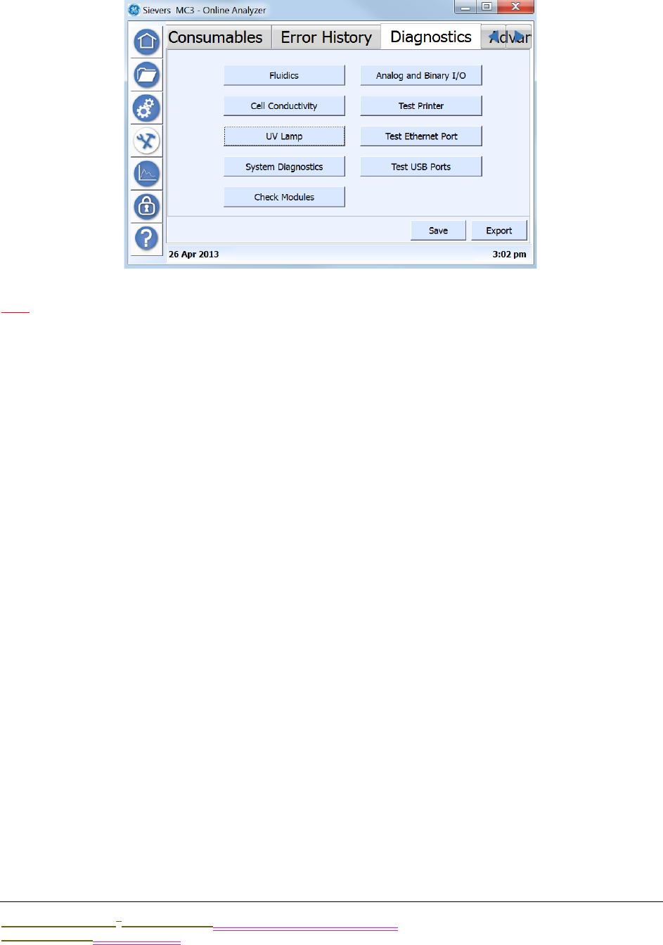
.................................
SETTINGS (CONSTANTS) EXPORT
Sievers M9 and M9e TOC AnalyzersSievers M5310 C TOC Analyzer Operation and Maintenance Manual
DLM 77000-01 DLM 77100-01 EN EN Rev. A GE Analytical Instruments © 2014
145 of 211
The Diagnostics Tab
WIP
•xxfluidics
•xxcell conductivity
•xxUV lamp
•xxsystem diagnostics
•xxcheck modules
•xxanalog and binary I/O
•xxtest printer
•xxtest Ethernet port
•xxtest USB port
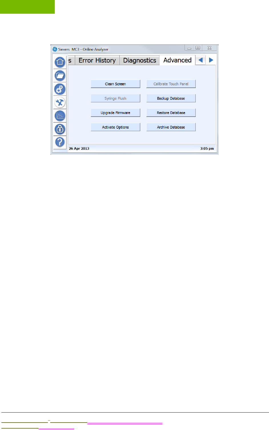
OPERATION
Chapter 5
Sievers M9 and M9e TOC AnalyzersSievers M5310 C TOC Analyzer Operation and Maintenance Manual
DLM 77000-01 DLM 77100-01 EN EN Rev. A GE Analytical Instruments © 2014
146 of 211
The Advanced Tab
Use the Advanced tab to xxxx
•Disable the touchscreen while cleaning
•Flush the syringes
•upgrade firmware
•activate options
•calibrate touch panel
•back up the database
•restore database
•archive database
Cleaning the Analyzer
This section includes suggested cleaning supplies and instructions for cleaning the Analyzer’s
external housing and touchscreen.
To clean the external housing
You will need a clean, soft cloth dampened with water or a non-abrasive cleaner, and
another clean, dry soft cloth.
1. Turn off power to the Analyzer and disconnect it from the main power source.
2. Wipe the external housing with a clean cloth dampened with water or a non-
abrasive cleaner.
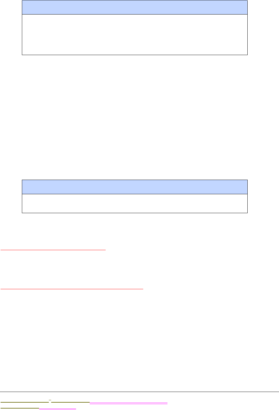
.................................
SETTINGS (CONSTANTS) EXPORT
Sievers M9 and M9e TOC AnalyzersSievers M5310 C TOC Analyzer Operation and Maintenance Manual
DLM 77000-01 DLM 77100-01 EN EN Rev. A GE Analytical Instruments © 2014
147 of 211
3. Wipe dry with another clean, dry soft cloth.
To clean the touchscreen
You will need a clean, soft (and dry) cloth or cotton pad. You may add a small amount
of methanol or isopropyl alcohol to the cloth, but ensure that all solvent residue is
removed first.
1. Disable the screen for cleaning. On the Maintenance screen, select the Advanced
tab.
2. Press CLEAN SCREEN to temporarily disable the screen for 30 seconds. Repeat, as
needed, if the 30-second time frame expires while cleaning.
3. Wipe the touchscreen with a clean, soft (and dry) cloth or cotton pad.
Flushing the syringes
Firmware development in progress.
Upgrading the Firmware
Research - information is not available in Demo.
WARNING
Always apply liquid to the cloth directly, and do NOT spray liquids directly on the
Analyzer.
Do NOT use water or cleaners on the touchscreen, as water can damage or discolor
the polarizer. Refer to the next section for recommendations on cleaning the
touchscreen.
WARNING
Do NOT use water as water can damage or discolor the polarizer. Clean any
condensation or moisture immediately.
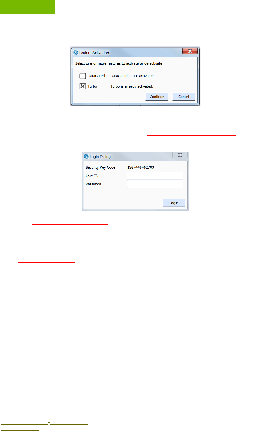
OPERATION
Chapter 5
Sievers M9 and M9e TOC AnalyzersSievers M5310 C TOC Analyzer Operation and Maintenance Manual
DLM 77000-01 DLM 77100-01 EN EN Rev. A GE Analytical Instruments © 2014
148 of 211
Activating DataGuard and Turbo Options
1. On the Maintenance screen, select the Advanced tab.
1. Select the option or options to activate. add text about must purchase.
2. Press CONTINUE to display the Login Dialog box.
3. Development in progress?
Calibrating the Touch Panel
xxxxxUnder development
1. ;lkjadf
2. ;lkjadf
3. ;lkjadf
4.
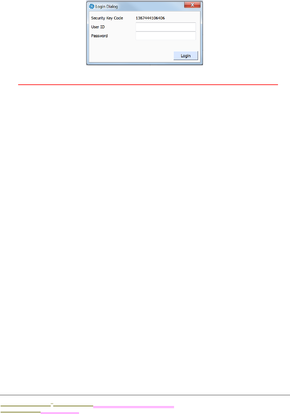
.................................
USING THE DATA VIEW SCREEN
Sievers M9 and M9e TOC AnalyzersSievers M5310 C TOC Analyzer Operation and Maintenance Manual
DLM 77000-01 DLM 77100-01 EN EN Rev. A GE Analytical Instruments © 2014
149 of 211
Backing up the Database
xxxxxIs the ability to perform this action set up in DataGuard (thus the user ID/password)?
1. ;lkjadf
2. ;lkjadf
•
•back up the database
•restore database
•archive database
USING THE DATA VIEW SCREEN
exporting data history
USING THE SECURITY/DATAGUARD SCREEN
Overview information
USING THE HELP SCREEN
Overview Information
USING THE ETHERNET CONNECTION AND MODBUS
different from 900
Figure 39: USB Connection Locations


7
..............................................
Sievers M9 and M9e TOC AnalyzersSievers M5310 C TOC Analyzer Operation and Maintenance Manual
DLM 77000-01 DLM 77100-01 EN Rev. A GE Analytical Instruments © 2014
155 of 211
CALIBRATION AND VERIFICATION
OVERVIEW
XXXXX
Verify not including System Suitability in 900e.
USING THE PROTOCOLS SCREEN
System Protocols and User Defined Methods
System Protocols
Calibration
Single Point Calibration
Sample Conductivity
Multi-point Calibration
TOC Autozero
TC / IC Cell Conductivity Autozero
Pharmacopoeia Test
System Suitability
Accuracy / Precision

CALIBRATION AND VERIFICATION
Chapter 7
Sievers M9 and M9e TOC AnalyzersSievers M5310 C TOC Analyzer Operation and Maintenance Manual
DLM 77000-01 DLM 77100-01 EN Rev. A GE Analytical Instruments © 2014
156 of 211
Validation
PROTOCOL 1 TEST
TEST SINGLESOURCE
;lkjasdf;kljadsf
•;lkjasdflkjasdf
•asd;flkjasdf;lkjasdf
•;lkjasdf;lkjasdf
heading 2
;lkjasdf;lkjasdf
as;lkjsdf
HEADING 3
;lkjaadf;lkjasdf
;lkjasdf;lkjafd
Heading 4
;lkj;lkj;kljasdf
;lkjasdf;lkjasdf


8
..............................................
Sievers M9 and M9e TOC AnalyzersSievers M5310 C TOC Analyzer Operation and Maintenance Manual
DLM 77000-01 DLM 77100-01 EN Rev. A GE Analytical Instruments © 2014
159 of 211
MAINTENANCE
This chapter is a WIP. An outline (as requested)
is provided for the safety review.
OVERVIEW
To ensure optimum performance of the Analyzer, perform the routine maintenance tasks
described in this chapter, and follow the recommended maintenance schedule outlined in this
chapter for the routine replacement of Analyzer consumables. Chemical reagents, the in-line
filter, UV lamp, and pump tubing MUST be purchased from GE Analytical Instruments.
NOTE: The use of reagents from other sources—or the failure to
replace the reagents on the prescribed replacement schedule—will
invalidate the Analyzer’s warranty.
This chapter applies to ALL Sievers M9 and M9e TOC AnalyzersSievers M5310 C TOC Analyzer
instrument models, except where noted. Step-by-step instructions for replacing consumables
are included, along with a convenient one-year Preventative Maintenance record log. See
Figure 44: 1-Year Maintenance Record Log (in the following section) for the recommended
maintenance schedule. Review and complete this record log to help you track and ensure
that all required preventive maintenance is performed on a regular schedule.
Service Kits for non-routine maintenance items are available from GE Analytical Instruments,
and come with step-by-step instructions, as needed.
If you need additional assistance when performing this preventative maintenance, contact
GE Analytical Instruments Technical Support at 800.255.6964. Technical Support in the United
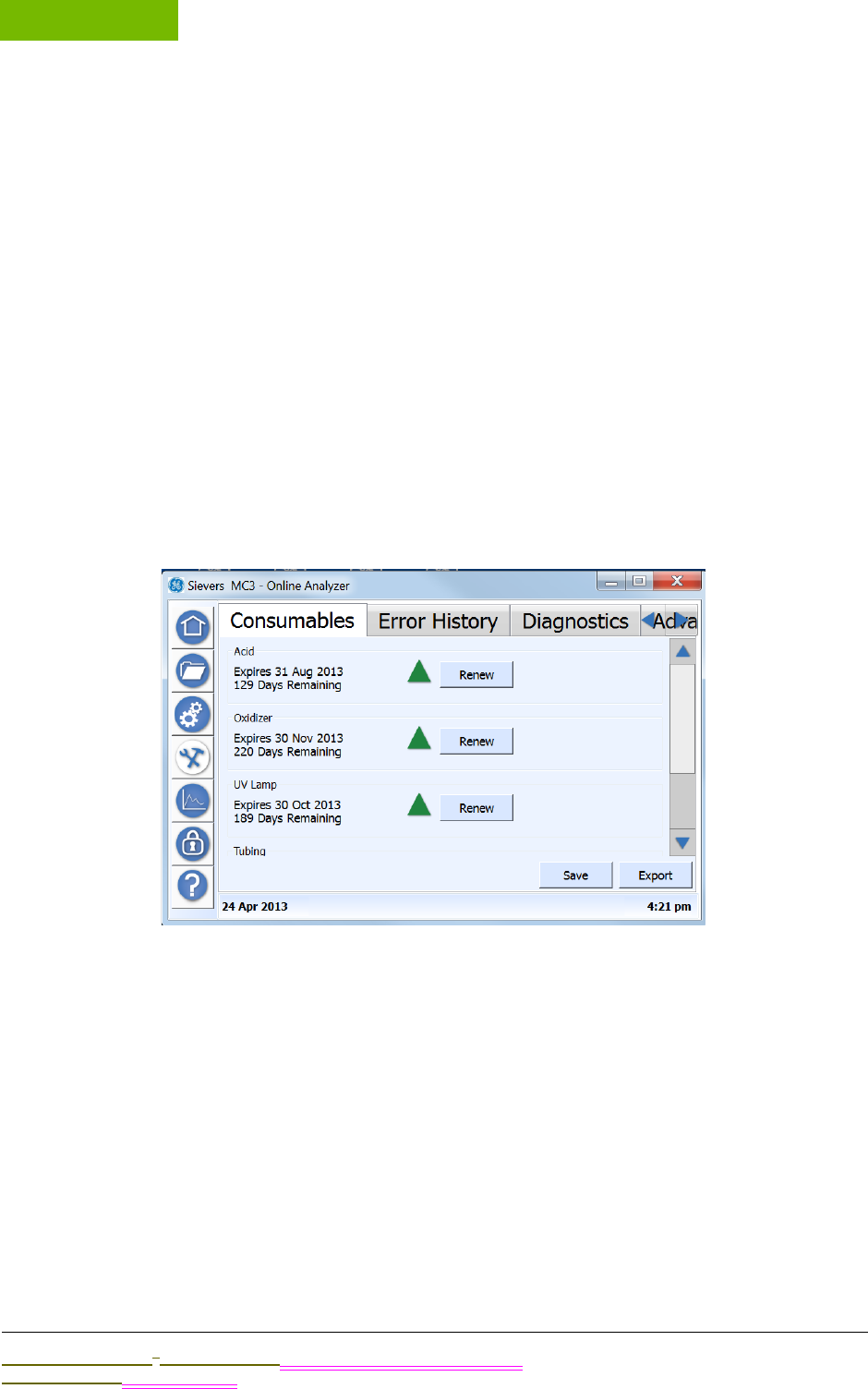
MAINTENANCE
Chapter 8
Sievers M9 and M9e TOC AnalyzersSievers M5310 C TOC Analyzer Operation and Maintenance Manual
DLM 77000-01 DLM 77100-01 EN Rev. A GE Analytical Instruments © 2014
160 of 211
Kingdom is available at 44 (0) 161 864 6800. In other countries, visit www.geinstruments.co to
locate your representative. Training by a qualified service technician also can be provided.
Interior Views of the Analyzer
Locate the diagram for your Analyzer model (On-Line, Laboratory, or Portable) in this
section, and refer to it as needed for performing the preventative maintenance described in
this chapter.
Figure 41: Interior Overview — On-Line TOC Analyzer
Figure 42: Interior Overview — Laboratory TOC Analyzer
Figure 43: Interior Overview — Portable TOC Analyzer
USING THE MAINTENANCE SCREEN
Overview
You will use this screen in the process of performing the following preventative maintenance
tasks:
•Entering and tracking consumables expiration (Consumables Tab)
•Flushing reagent syringes (Advanced Tab)
•Temporarily disabling the screen for cleaning (Advanced Tab)

.................................
PERFORMING ROUTINE MAINTENANCE TASKS
Sievers M9 and M9e TOC AnalyzersSievers M5310 C TOC Analyzer Operation and Maintenance Manual
DLM 77000-01 DLM 77100-01 EN Rev. A GE Analytical Instruments © 2014
161 of 211
You will also use this Maintenance screen to access the tabs for the following operational
maintenance tasks, as described in other chapters (as listed):
•Error History Tab — Review the list of errors and warnings issued by the Analyzer during
operation of the instrument. Step-by-step instructions, and error/warning descriptions, are
included in Chapter 9, "Troubleshooting."
•Diagnostics Tab — Use this tab to perform diagnostic activities when troubleshooting
operational and analyses issues, Information and instructions are included in Chapter 9,
"Troubleshooting."
•Advanced Tab — Use this tab to upgrade firmware, activate options, back up the database,
back up settings, archive the database, calibrate the touch panel, restore the database,
and restore settings. This tab and the related step-by-step instructions are included in
Chapter 5, "Operation."
PERFORMING ROUTINE MAINTENANCE TASKS
;lkjasdf;kljadsf:
•Flushing Reagent Syringes
•Maintaining the DI Water Reservoir Level
•Cleaning the Analyzer
Flushing Reagent Syringes
If the Analyzer has not been used for over 24 hours, the decomposition of persulfate can
produce oxygen bubbles in the syringe pump and the reagent addition lines. To prevent
bubbles from entering the sample stream and interfering in the TOC measurement, a reagent
flush is used to remove the bubbles and fill the syringe with fresh reagent. A reagent flush
also is recommended after installing new chemical reagents.
For the reagent flush, the Analyzer must be connected to a water supply. A 40-mL vial of
water, or on-line water, may be used for the reagent flush.
Firmware development in progress.
xxxxUse the Advanced Tab .....
To flush the reagent syringes
1. ;lkjadsf
2.

MAINTENANCE
Chapter 8
Sievers M9 and M9e TOC AnalyzersSievers M5310 C TOC Analyzer Operation and Maintenance Manual
DLM 77000-01 DLM 77100-01 EN Rev. A GE Analytical Instruments © 2014
162 of 211
Maintaining the DI Water Reservoir Level
Periodically check xxxxx and fill the reservoir as needed
Single-source from Installation Chapter.
To fill the DI water reservoir
1. ;lkjasdf
2. ;lkajsdf
3. ;lkjasdf
Cleaning the Analyzer
Along with replacing consumables, you will need to clean the house and touchscreen, as part
of your routine preventative maintenance tasks.
This section includes suggested cleaning supplies and instructions for cleaning the Analyzer’s
external housing and touchscreen.
To clean the external housing
You will need a clean, soft cloth dampened with water or a non-abrasive cleaner, and
another clean, dry soft cloth.
1. Turn off power to the Analyzer and disconnect it from the main power source.
2. Wipe the external housing with a clean cloth dampened with water or a non-
abrasive cleaner.
3. Wipe dry with another clean, dry soft cloth.
To clean the touchscreen
You will need a clean, soft (and dry) cloth or cotton pad. You may add a small amount
of methanol or isopropyl alcohol to the cloth, but ensure that all solvent residue is
removed first.
WARNING
Always apply liquid to the cloth directly, and do NOT spray liquids directly on the
Analyzer.
Do NOT use water or cleaners on the touchscreen, as water can damage or discolor
the polarizer. Refer to the next section for recommendations on cleaning the
touchscreen.

.................................
REPLACING CONSUMABLES OVERVIEW
Sievers M9 and M9e TOC AnalyzersSievers M5310 C TOC Analyzer Operation and Maintenance Manual
DLM 77000-01 DLM 77100-01 EN Rev. A GE Analytical Instruments © 2014
163 of 211
1. Disable the screen for cleaning. On the Maintenance screen, select the Advanced
tab.
2. Press CLEAN SCREEN to temporarily disable the screen for 30 seconds. Repeat, as
needed, if the 30-second time frame expires while cleaning.
3. Wipe the touchscreen with a clean, soft (and dry) cloth or cotton pad.
REPLACING CONSUMABLES OVERVIEW
XXXXX:
•Replacing Consumable Items
•Replacing the UV Lamp
•Replacing the Pump Heads
•Replacing the Resin Cartridge
•Replacing the UV Lamp
•Replacing the In-Line Filter Element
•Replacing the ICR Chemical Trap (ICR users ONLY)
Maintenance Schedule
xxxxx
Add Maintenance table - Mention reagent replacement data collected by RFID
Why write these down when they are available in the instrument?
chemical trap (ICR-optional) - 1 yr.
Figure 44: 1-Year Maintenance Record Log
Tracking Consumables Expiration Dates
You can view the expiration date and number of remaining days for the following
consumables on this tab:
WARNING
Do NOT use water as water can damage or discolor the polarizer. Clean any
condensation or moisture immediately.

MAINTENANCE
Chapter 8
Sievers M9 and M9e TOC AnalyzersSievers M5310 C TOC Analyzer Operation and Maintenance Manual
DLM 77000-01 DLM 77100-01 EN Rev. A GE Analytical Instruments © 2014
164 of 211
•Acid
•Oxidizer
•UV Lamp
•Tubing
•Resin Bed
A triangle icon appears next to the RENEW button to indicate the severity of the expiration
date: green (adequate time frame) Is there a yellow(?), or red (Expiration nearing). Use this tab
to reset the expiration date after replacing a consumable item.
To renew an expiration date
Include a note about the RFID tracking of Reagent Consumables. This Consumables
section should only be used to enter older GE manufactured cartridges that do not
include RFID technology (i.e. Model 900 cartridges).
Include a second note that the Analyzer automatically configures reagent information
using the RFID technology.
After replacing the consumables item in the Analyzer.....
1. On the Maintenance screen, select the Consumables tab.
2. Press the RENEW button next to the consumable item you have replaced. (feature
not yet implemented)
3. xxx
4. xxx
5. Press SAVE.
Replacing Consumable Items
;lkjasdf;lkjasdf:
•Replacing the Resin Cartridge
•Replacing the Chemical Reagents
•Replacing the UV Lamp
•Replacing the Pump Heads
•Replacing the In-Line Filter Element
•Replacing the ICR Chemical Trap (ICR users ONLY)

.................................
REPLACING CONSUMABLES OVERVIEW
Sievers M9 and M9e TOC AnalyzersSievers M5310 C TOC Analyzer Operation and Maintenance Manual
DLM 77000-01 DLM 77100-01 EN Rev. A GE Analytical Instruments © 2014
165 of 211
REPLACING THE RESIN CARTRIDGE
Replacing the Ion Exchange xxx
Single-Source from the installation chapter.
To replace the resin cartridge
1. ;lkjadsf
2.
REPLACING THE CHEMICAL REAGENTS
;lkjasdfFollow with flushing the reagent syringes as described in the previous section.
To replace the reagent cartridges
1. ;lkjadsf
2.
Using a vial
REPLACING THE UV LAMP
;lkjasdf
To replace the UV Lamp
1. ;lkjadsf
2.
REPLACING THE PUMP HEADS
xxxx(previously replacing the sample pump tubing...mention this advantage)
To replace the pump heads
1. ;lkjadsf
2.
REPLACING THE IN-LINE FILTER ELEMENT
xxxx

MAINTENANCE
Chapter 8
Sievers M9 and M9e TOC AnalyzersSievers M5310 C TOC Analyzer Operation and Maintenance Manual
DLM 77000-01 DLM 77100-01 EN Rev. A GE Analytical Instruments © 2014
166 of 211
To replace the in-line filter element
1. ;lkjadsf
2.
3.
REPLACING THE ICR CHEMICAL TRAP (ICR USERS ONLY)
xxxx
To replace the chemical trap
1. ;lkjadsf
2.
3.
4.
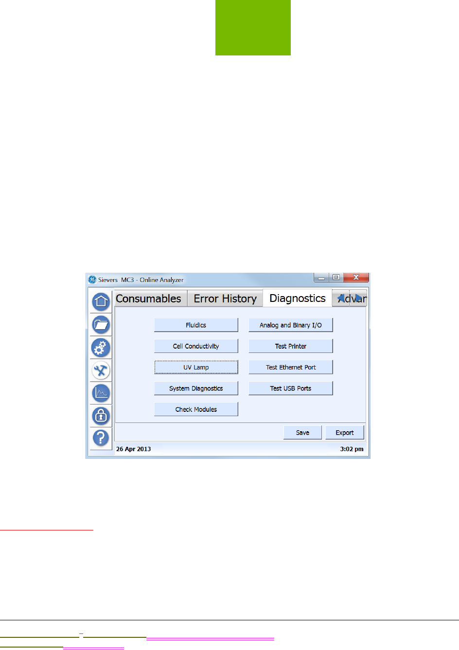
9
..............................................
Sievers M9 and M9e TOC AnalyzersSievers M5310 C TOC Analyzer Operation and Maintenance Manual
DLM 77000-01 DLM 77100-01 EN Rev. A GE Analytical Instruments © 2014
167 of 211
TROUBLESHOOTING
OVERVIEW
XXXXX
The Diagnostics Tab
WARNING AND ERROR MESSAGES
Add link messages.
Inspect
Constants

TROUBLESHOOTING
Chapter 9
Sievers M9 and M9e TOC AnalyzersSievers M5310 C TOC Analyzer Operation and Maintenance Manual
DLM 77000-01 DLM 77100-01 EN Rev. A GE Analytical Instruments © 2014
168 of 211
Error
Diagnostics
ICEFOME
Flow Backflow
Oxidizer
Data
USING THE HELP SCREEN
Overfilling the DI Water reservoir
xxxxx
To drain excess water from the DI water reservoir
You will need the Dispensing bottle (with attached filling fixture) and the individual
(loose) elbow fitting from the Analyzer’s Accessories Kit. You will also need a flask or
beaker (size?) to collect the excess DI water.
1. Press the latch of the Prime port down and insert the individual (loose) elbow
fitting,
2. Remove the tip of the dispensing bottle from the tubing of the Dispensing bottle
assembly. See Figure 45: Dispensing Bottle Tip.
3. Press the latch of the DI pump outlet up and insert the elbow-fitting end of the
tubing into the DI pump outlet. (The outlet is located between the IC and TC sample
pumps). Reference Figure 22: Inserting the DI Loop Fill Tube.)
4. Direct the other end of the tubing into a flask or beaker, located below the DI pump
outlet. The water will automatically flow out the tubing in this gravity-drain
position.
5. Verify that the water line is JUST BELOW the top of the reservoir, as shown in
Figure 23: Filling the DI Water Reservoir (with attached filling fixture).
Figure 45: Dispensing Bottle Tip
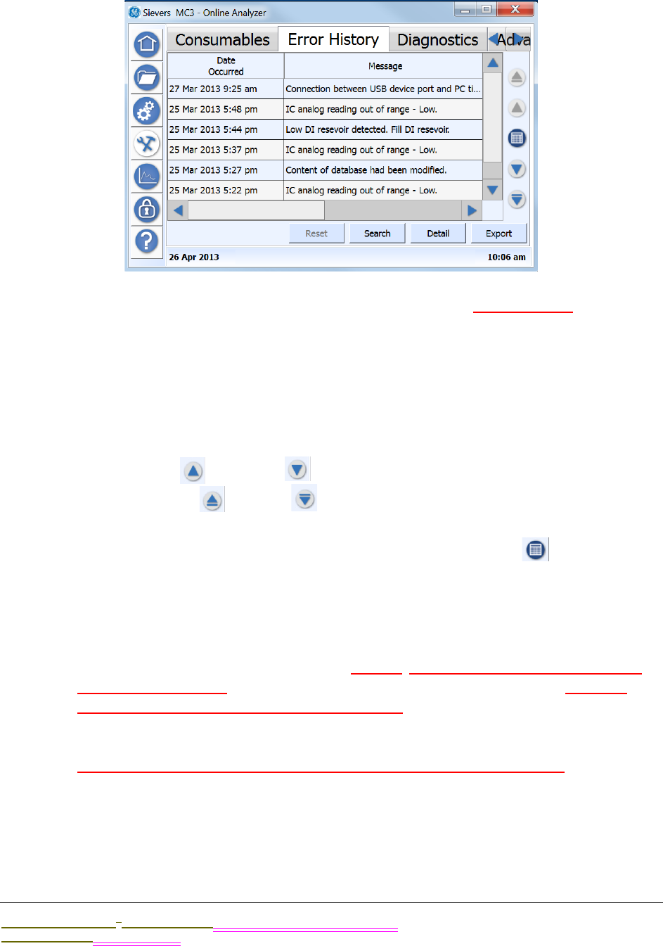
.................................
WARNING AND ERROR MESSAGES
Sievers M9 and M9e TOC AnalyzersSievers M5310 C TOC Analyzer Operation and Maintenance Manual
DLM 77000-01 DLM 77100-01 EN Rev. A GE Analytical Instruments © 2014
169 of 211
The Error History Tab
You can use this tab to search and view a cumulative list of recent and historical errors and
warnings.
To view error and warning history
1. Use the vertical scrollbar to move through a list of recent messages (listed most
recent to oldest). Or, use one of the following buttons to scroll through the
messages:
•Use the UP and DOWN arrows to skip forward and backward by a page.
•Use the START and END arrows to take you to the most recent or oldest
message (respectively).
2. To search for messages for a specific date, press the CALENDAR icon to display
the Calendar dialog box. Use the navigation arrows (as needed) to locate the date,
and then press the day to view.
The Analyzer automatically returns you to the Validation History tab with any
messages from the selected date displayed.
3. To search for messages by a keyword, User ID, Is this separate from keyword or
combined with/how? AND/OR the date acknowledged, press SEARCH. Can you
change the categories by which to search by?The Search dialog box appears.
Otherwise, go to step 4.
4. (Return to verify these steps after Search development is completed.)To include a
keyword or keyword string in the search, select KEYWORD SEARCH, and then press
inside the Keyword Search field to display the alpha/numeric keypad. Type a word
or string of words to find.
The word (or string of words) appears in the Keyword Search field.
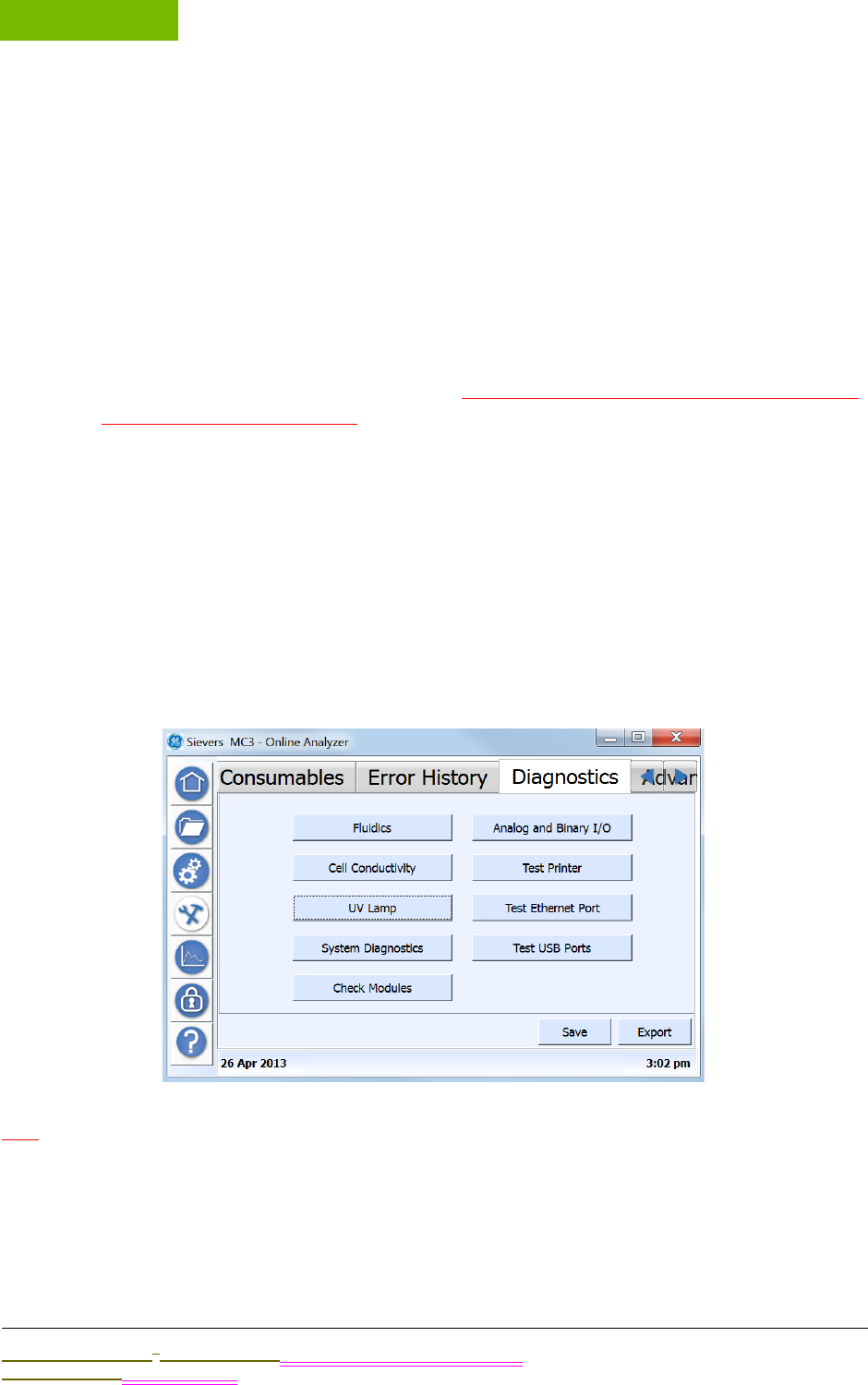
TROUBLESHOOTING
Chapter 9
Sievers M9 and M9e TOC AnalyzersSievers M5310 C TOC Analyzer Operation and Maintenance Manual
DLM 77000-01 DLM 77100-01 EN Rev. A GE Analytical Instruments © 2014
170 of 211
5. To include a date range in the search, do the following:
•Select DATE ACKNOWLEDGED, and then press inside the Start Date field to display
the Start Date dialog box. Use the navigation arrows (as needed) to locate the
date, and then press the first day in the range to view.
The Analyzer automatically returns you to the Search dialog box.
•Press inside the END DATE field to display the End Date dialog box. Use the
navigation arrows (as needed) to locate the date, and then press the last day
date in the range to view.
6. Press SEARCH. The Analyzer returns to the Search dialog box, and displays the
messages meeting the search criteria. (Return to modify these steps after Search
development is completed.)
7. Use the horizontal scrollbar to move to the right and back to left to view message
information, such as Date Occurred, Message (Text), Acknowledged By, and Date
Acknowledged.
8. To view additional details of any message, select the message line and press
DETAIL. A summary of the message appears including additional information, such
as error level (Error or Warning) and module reported.
9. Press OK to return to the Error History tab.
The Diagnostics Tab
WIP
•xxfluidics
•xxcell conductivity
•xxUV lamp

.................................
WARNING AND ERROR MESSAGES
Sievers M9 and M9e TOC AnalyzersSievers M5310 C TOC Analyzer Operation and Maintenance Manual
DLM 77000-01 DLM 77100-01 EN Rev. A GE Analytical Instruments © 2014
171 of 211
•xxsystem diagnostics
•xxcheck modules
•xxanalog and binary I/O
•xxtest printer
•xxtest Ethernet port
•xxtest USB port


A
..............................................
Sievers M9 and M9e TOC AnalyzersSievers M5310 C TOC Analyzer Operation and Maintenance Manual
DLM 77000-01 DLM 77100-01 EN Rev. A GE Analytical Instruments © 2014
175 of 211
Appendix A: WARNINGS
Working with Intertek
English
WARNINGS
Shipping boxes containing an Analyzer with built-in
optional components may weigh over 40 lb —
necessitating a two-person lift technique when handling.
Such boxes are labeled with this warning, supporting
OSHA standards intended to protect employees from
injury.
We recommend that our customers use a two-person lift,
and GE requires that ALL employees use this handling
technique when lifting items weighing over 40 lb.
This symbol on the instrument indicates that the user
should refer to the manual for operating instructions.
If this instrument is used in a manner not specified by
GE Analytical Instruments, the safety protection provided
by the instrument may be impaired.
WARNINGS
Appendix A
Sievers M9 and M9e TOC AnalyzersSievers M5310 C TOC Analyzer Operation and Maintenance Manual
DLM 77000-01 DLM 77100-01 EN Rev. A GE Analytical Instruments © 2014
176 of 211
(On-Line TOC Analyzer) This symbol indicates the
protective earth terminal (ground) for the Analyzer.
The Analyzer requires an A/C mains supply of 100-240
volts, and requires the correct power cord for safe
operation. ONLY use the power cord supplied in the
Analyzer’s Accessory Kit with the Analyzer, which meets
this A/C mains supply requirements.
For safety reasons and to avoid the possibility of
corrupting the database, ALWAYS follow this procedure
when shutting down the Analyzer. First stop analysis AND
stop the operating system (using the HALT SYSTEM button
in the Analyzer’s firmware) BEFORE pressing the
Analyzer’s power switch to Off or unplugging the power
cord,
Any operation requiring access to the inside of the
Analyzer, including installation of maintenance items,
could result in injury. To avoid potentially dangerous
shock—BEFORE opening the Analyzer—first stop any
analysis, stop the operating system (using HALT SYSTEM
button in the Analyzer’s firmware), and then turn off
power and disconnect from the power supply
Electrical conduit should be installed by a qualified
electrician. Also, before installing any wiring inside the
Analyzer, make sure you are wearing ESD protection.
The output and alarm connections should be installed by
a qualified electrician. Also, before installing any wiring
inside the Analyzer, make sure you are wearing ESD
protection.
This is a Class A product. In a domestic environment, this
product may cause electromagnetic interference in which
case the user may be required to take adequate
measures to correct the interference.
To protect against accidental exposure to ultra-violet
radiation, do not operate the UV lamp outside of its
protective housing.
WARNINGS
.................................
WARNINGS
Sievers M9 and M9e TOC AnalyzersSievers M5310 C TOC Analyzer Operation and Maintenance Manual
DLM 77000-01 DLM 77100-01 EN Rev. A GE Analytical Instruments © 2014
177 of 211
(On-Line and Portable TOC Analyzers) Water in the iOS
System may be hot. Before inserting a vial into the iOS
System after operating in on-line mode, slide the door
open and wait 30 seconds to allow sample to completely
drain. Inserting a vial before draining can result in hot
water spray projecting upward out of the iOS System or
vial port.
The iOS System and vial ports contain sharp needles
designed to pierce the septa of sample vials. Do NOT put
fingers or inappropriate materials into the iOS System or
vial port.
When servicing parts inside the Analyzer, ensure that
power to the Analyzer is off, and keep hands clear of the
reagent syringe assemblies. The syringes are controlled
by moving parts that can pinch skin.
(Laboratory and Portable TOC Analyzers) For continued
protection against fire hazard, replace fuse with same
type and rating.
WARNINGS

WARNINGS
Appendix A
Sievers M9 and M9e TOC AnalyzersSievers M5310 C TOC Analyzer Operation and Maintenance Manual
DLM 77000-01 DLM 77100-01 EN Rev. A GE Analytical Instruments © 2014
178 of 211
WARNINGS
Changes or modifications to the RFID radio not expressly approved by
the party responsible for compliance could void the user's authority to
operate the equipment.
This device complies with Part 15 of the FCC Rules & Industry Canada
license-exempt RSS standards. Operation is subject to the following two
conditions:
(1) This device may not cause harmful interference, and
(2) This device must accept any interference received, including
interference that may cause undesired operation.
The RFID antenna is a Part 15 & RSS-210 - Class A digital device:
This equipment has been tested and found to comply with the limits for
a Class A digital device, pursuant to part 15 of the FCC Rules. These
limits are designed to provide reasonable protection against harmful
interference when the equipment is operated in a commercial
environment. This equipment generates, uses, and can radiate radio
frequency energy and, if not installed and used in accordance with the
instruction manual, may cause harmful interference to radio
communications. Operation of this equipment in a residential area is
likely to cause harmful interference in which case the user will be
required to correct the interference at his own expense.
This equipment complies with FCC electromagnetic radiation exposure
limits set forth for an uncontrolled environment. This equipment should
be installed and operated with a minimum separation distance of 20cm
(7 in.) between the RFID antenna and your body. The antenna is located
on the inside floor of the Analyzer near the front of the syringe
assemblies.
.................................
WARNINGS
Sievers M9 and M9e TOC AnalyzersSievers M5310 C TOC Analyzer Operation and Maintenance Manual
DLM 77000-01 DLM 77100-01 EN Rev. A GE Analytical Instruments © 2014
179 of 211
HAZARDOUS MATERIAL DISPOSAL
The following guidelines are provided to aid you in discarding and the disposal of
hazardous substances related to the Sievers M9 and M9e TOC
AnalyzersSievers M5310 C Analyzer.
OPERATIONAL CAUTIONS
To ensure optimal sampling results and to protect the instrument from any damage,
review and implement the following Caution statements.
HAZARDOUS MATERIAL DISPOSAL
Hazardous reagents (ammonium persulfate and phosphoric acid) are
used in the Analyzer. The waste stream from the instrument is acidic and
must be disposed of properly. Consult your federal, state, and local
government regulations.
The UV lamp and the display screen contain mercury and may be
considered hazardous material in your local area. Dispose of these items
in accordance with federal, state, or local government regulations.
In the case of any broken or damaged UV lamp, handle the remains in
accordance with your organization’s toxic waste handling procedure
and dispose of them in accordance with federal, state, or local
government regulations.
This symbol indicates the European Union Directive 2002/96/EC
for waste electrical and electronic equipment (WEEE) requires
disposing the Analyzer separately from standard waste.
CAUTIONS
Make sure the DI water Reservoir is full, particularly when running
samples with high TOC or high salt concentrations. After running high
TOC or salt samples, always rinse the Analyzer by running low-TOC DI
water through a sample cycle.
To avoid false TOC readings and possible damage to the Analyzer,
always make sure the sample inlet is open and the DI water reservoir is
filled before starting analysis
Operation of the Analyzer without the in-line filter on the sample inlet
line will damage the Analyzer and void the warranty. To avoid damaging
the Analyzer, install the filter and replace the filter element, as needed.
WARNINGS
Appendix A
Sievers M9 and M9e TOC AnalyzersSievers M5310 C TOC Analyzer Operation and Maintenance Manual
DLM 77000-01 DLM 77100-01 EN Rev. A GE Analytical Instruments © 2014
180 of 211
To avoid false TOC readings and possible damage to the Analyzer,
always make sure the sample is flowing through the iOS System and the
DI water reservoir is filled before starting analysis.
For performance within specifications on ozonated water systems, an
Ozone Destruct Kit must be purchased from GE Analytical Instruments
and installed according to instructions.
When cleaning the Analyzer, always apply liquid to the cloth directly,
and do NOT spray liquids directly on the Analyzer.
Do NOT use water or cleaners on the touchscreen, as water can
damage or discolor the polarizer. Refer to the next section for
recommendations on cleaning the touchscreen.
Wipe away any condensation immediately.
CAUTIONS
.................................
WARNINGS
Sievers M9 and M9e TOC AnalyzersSievers M5310 C TOC Analyzer Operation and Maintenance Manual
DLM 77000-01 DLM 77100-01 EN Rev. A GE Analytical Instruments © 2014
181 of 211
中文 (Chinese)
警告
装有分析仪及内置可选组件的发货箱的重量可能超过
40 磅,移动时需要由两个人抬起。此类重量的箱子贴
有此警告,意在遵循保护员工免受伤害的 OSHA 标准。
我们建议用户由两个人抬起重物,GE 要求所有员工在
移动 40 磅重量以上的物体时,均采取两人抬起的方
法。
仪器上标有此符号表示用户应参考手册上的操作说明。
如果该仪器以 GE Analytical Instruments 公司所未
规定的方式使用,该仪器所提供的保护作用可能会被削
弱。
(
在线型 TOC 分析仪
)此符号表示分析仪的保护性接地
端 (地线)。
分析仪要求 100-240 伏的 A/ C 电源及正确的电源线,
以保证安全工作。只可使用分析仪配件包中提供的电源
线,该电源线符合分析仪的 A/ C 电源要求。
出于安全考虑,并且为了避免损坏数据库,在关机时应
始终按照以下操作程序。在将分析仪的电源开关切换到
关闭或拔掉电源线之前,应首先停止分析,并且停止正
在运行的系统 (用分析仪固件中的系统停机按键)。
任何需要接触分析仪内部的操作,包括安装维修件,均
可能导致人身伤害。为避免可能的电击伤害,在打开分
析仪机壳之前,应首先停止任何分析,并停止正在运行
的系统 (用分析仪固件中的系统停机按键),然后关闭
电源开关,并断开电源连接。
应由合格的电工来安装电气管路。在分析仪内安装和布
线之前,应确保佩戴 ESD 保护。
应由合格的电工来安装输出和警报连接。在分析仪内安
装和布线之前,应确保佩戴 ESD 保护。
WARNINGS
Appendix A
Sievers M9 and M9e TOC AnalyzersSievers M5310 C TOC Analyzer Operation and Maintenance Manual
DLM 77000-01 DLM 77100-01 EN Rev. A GE Analytical Instruments © 2014
182 of 211
有害物质处理
以下指导帮助您正确处理和弃置 Sievers M9 and M9eM5310 C TOC 分析仪使用的有
害物质。
本产品为 A 类产品。在家庭环境中,本产品可能导致
电磁干扰,用户可能需要采取适当措施以减少干扰。
为防止意外暴露在紫外线放射下而导致伤害,请勿将紫
外线灯置于保护罩之外。
(
在线型和便携式
TOC
分析仪
)iOS 系统中的水可能会
很热。在在线模式下运行之后,请将门滑开,等待 30
秒,使样品完全排空,然后将样品瓶插入 iOS 系统。如
果在排空之前插入样品瓶,可能导致热水向上喷射出
iOS 系统或样瓶端口。
IOS 系统和试剂瓶槽含有两个锐利的针头,用于刺穿试
样试剂瓶的封口膜。请不要将手指或其它不适当的物体
放入 IOS 系统或试剂瓶槽。
在维修分析仪中的部件时,应先确保关闭分析仪的电
源,不可将手靠近试剂注射器部件。注射器由移动部件
控制,可能会夹伤皮肤。
(
实验室型和便携式
TOC
分析仪
)为预防火灾,请使用
相同类型和规格的保险丝进行更换。
有害物质处理
此分析仪使用危险试剂 (过硫酸铵和磷酸)。分析仪排出的废液呈酸
性,必须妥善处理。应按照联邦、州/省或地方政府的相关规定进行
处理。
紫外线灯和显示屏含有汞,在您所在的地区可能被视为危险材料。处
理这些材料时,请遵循国家、州/省或地方政府的相关规定。
如果紫外线灯破损或损坏,应根据您所在单位的有毒废料处理程序以
及联邦、州/省或地方政府的相关规定进行处理。
警告
.................................
WARNINGS
Sievers M9 and M9e TOC AnalyzersSievers M5310 C TOC Analyzer Operation and Maintenance Manual
DLM 77000-01 DLM 77100-01 EN Rev. A GE Analytical Instruments © 2014
183 of 211
操作注意事项
为了确保最佳取样结果,并且保护仪器不受损坏,请阅读并执行注意事项。
此符号表示根据欧盟废电机电子设备 (WEEE) 指令
2002/96/EC,分析仪应以不同于普通废品的方式处理。
注意事项
应确保 DI 水容器中装满水,特别是在测试高 TOC 或高盐浓度的试
样时尤其如此。在测试完高 TOC 或高盐浓度的试样后,请务必使用
低 TOC 的 DI 水冲洗样品环路。
为避免 TOC 读数错误或损坏分析仪,在开始分析前必须保证试样进
口打开且 DI 水容器已满。
在进样管中没有安装联线过滤器的情况下操作分析仪,会损坏仪器并
使保修失效。为了避免损坏分析仪,应安装过滤器,并根据需要按时
更换滤芯。
为了避免错误的 TOC 读数,为了避免损坏分析仪,在开始分析之前,
请务必确保样品流经 iOS 系统,确保 DI 水容器中装满水。
对于在臭氧水系统规格内的运行,必须从
GE Analytical Instruments 购买臭氧破坏套件,并按说明进行安
装。
在清洁分析仪时,应将清洁液放在抹布上,不可将清洁液直接喷洒在
分析仪上。
不可在触摸屏上使用水或清洁剂,水可以使偏振片损坏或褪色。请参
阅后面的章节了解触摸屏的清洁方法。应立即擦去触摸屏上的冷凝
水。
有害物质处理
WARNINGS
Appendix A
Sievers M9 and M9e TOC AnalyzersSievers M5310 C TOC Analyzer Operation and Maintenance Manual
DLM 77000-01 DLM 77100-01 EN Rev. A GE Analytical Instruments © 2014
184 of 211
日本語 (Japanese)
警告
内蔵のオプション コンポーネントを備えた分析装置
を含む発送用箱は 40 lb (18 kg) を超える重さがあ
る可能性があり、取り扱う時には 2 人で持ち上げる
方法が必要になります。 このような箱にはこの警告が
記されたラベルが貼られ、従業員を怪我から守ること
を目的とした OSHA 基準に対応しています。
お客様は 2 人で持ち上げる方法を用いることをお勧
めします。そして GE では、40 lb (18 kg) を超える
重さがある製品を持ち上げる時にはすべての従業員が
この取扱方法を用いることを求めています。
機器についているこの記号は、ユーザーが操作指示書
を参照する必要があることを示します。
この機器が GE Analytical Instruments によって指定
された方法で使用されなかった場合、機器に組み込ま
れた保護機能は損なわれます。
(
オンライン型 TOC 分析装置
) このマークは、分析
装置の保護アース端子 ( グランド ) を示しています。
分析装置は 100 ~ 240 ボルトの A/C 主電源を必要
とし、安全な運転のために正しい電源コードを必要と
します。 分析装置アクセサリ キットに付属の電源
コードのみを使用してください。このコードは A/C
主電源の要件を満足します。
安全のため、そしてデータベースを破損する可能性を
避けるため、分析装置の電源を切る時には必ずこの手
順に従ってください。 分析装置の電源スイッチを押し
てオフ (Off) にするか、電源コードを抜く前に、ま
ず分析を停止し、かつオペレーティング システムを
停止します ( 分析装置のファームウェアのシステム
停止 (HALT SYSTEM) ボタンを用いて )。
保守品目の取り付けを含む、分析装置内部にアクセス
するいかなる操作も、人身傷害につながる可能性があ
ります。 分析装置を開ける前に、潜在的に危険な衝撃
を避けるために、まず分析を停止し、オペレーティン
グ システムを停止し ( 分析装置のファームウェアに
あるシステム停止 (HALT SYSTEM) ボタンを用いて )、
その後、電源を切り、電源供給から切り離します。
.................................
WARNINGS
Sievers M9 and M9e TOC AnalyzersSievers M5310 C TOC Analyzer Operation and Maintenance Manual
DLM 77000-01 DLM 77100-01 EN Rev. A GE Analytical Instruments © 2014
185 of 211
電気導管は、有資格の電気技術者が行ってください。
また、分析装置内部の配線を行う前に、静電気放電防
止用ストラップを着用するようにしてください。
出力および警報の接続は、有資格の電気技術者が行っ
てください。 また、分析装置内部の配線を行う前に、
静電気放電防止用ストラップを着用するようにしてく
ださい。
これはクラス A の製品です。 屋内環境においては、
この製品は電磁干渉を発生することがあり、その場合
はユーザーが適切な是正措置を取る必要があります。
紫外線への偶発的な曝露から身を守るために、保護容
器の外で UV ランプを作動させないでください。
(
オンライン型およびポータブル型 TOC 分析装置
)
iOS システム内の水が加熱している場合があります。
オンライン モードでの運転後にバイアルを iOS シス
テムに挿入する前に、ドアをスライドさせて開け、30
秒間待ち、サンプルが完全に排水されるようにしてく
ださい。 排水前にバイアルを挿入すると、iOS システ
ムまたはバイアル ポートから熱水が噴出するおそれ
があります。
iOS システムおよびバイアル ポートには、サンプル
バイアルのセプタムを穿孔するように設計された鋭利
なニードルが含まれています。 指や不適切な物質を
iOS システムやバイアル ポートに入れないようにし
てください。
分析装置の内部にある部品を修理する際、分析装置へ
の電源が切れていることを確認し、試薬シリンジ ア
センブリに手を近付けないようにしてください。 シリ
ンジは、指を挟む危険のある可動部品によって制御さ
れています。
(
ラボ型およびポータブル型 TOC 分析装置
) 火災の
危険から引き続き守るために、同じ型式で定格の
フューズと交換してください。
警告
WARNINGS
Appendix A
Sievers M9 and M9e TOC AnalyzersSievers M5310 C TOC Analyzer Operation and Maintenance Manual
DLM 77000-01 DLM 77100-01 EN Rev. A GE Analytical Instruments © 2014
186 of 211
有害物質処分
以下の指針は、SieversM9 and M9eM5310 C TOC 分析装置に関連した有害物質を
廃棄および処分するうえで支援するために示されています。
操作上の注意
最適なサンプリング結果を確保するため、そして機器を損傷から守るために、
以下の注意に関する記述を見直し、実践してください。
有害物質処分
分析装置には危険な試薬 ( 過硫酸アンモニウムやリン酸 ) が使用
されています。 機器から出る排水は酸性であり正しい方法で廃棄す
る必要があります。 国、州、および地方自治体の政府規制に従って
ください。
UV ランプおよびディスプレイ画面には水銀が含まれており、地域
によっては水銀が有害物質に指定されている場合があります。 これ
らの部品は、国や地方自治体の規制に従って処分してください。
UV ランプが切れたか損傷を受けた場合は、社内の有害廃棄物取扱
手順に従って残留物を取り扱い、国、都道府県、または地方自治体
の規則に従って処分してください。
この記号は、廃電気電子機器 (WEEE) に関する EU 指令
2002/96/EC では、標準の廃棄物とは別に分析装置を処分す
ることを求めていることを示します。
注意
DI 水リザーバーが満杯になっていることを確認してください。特
に、TOC または塩分の濃度が高いサンプルを使用する場合に重要
です。 TOC または塩分の濃度が高いサンプルを使用した後は、サ
ンプル サイクルを通じて 低 TOC の DI 水を流すことで、必ず分
析装置を洗浄してください。
誤った TOC 測定値および分析装置に対する損傷の可能性を避ける
ために、分析を開始する前に、サンプル注入口が開いていて、DI
水リザーバーが満杯になっていることを必ず確認してください。
サンプル注入口ラインにインライン フィルターを取り付けていな
い状態で分析装置を操作すると、分析装置に損傷を及ぼし、保証
が無効になります。 分析装置の損傷を防ぐために、フィルターを
取り付け、必要に応じてフィルター エレメントを交換してくださ
い。
.................................
WARNINGS
Sievers M9 and M9e TOC AnalyzersSievers M5310 C TOC Analyzer Operation and Maintenance Manual
DLM 77000-01 DLM 77100-01 EN Rev. A GE Analytical Instruments © 2014
187 of 211
誤った TOC 測定値や分析装置に対する損傷の可能性を避けるため
に、分析を開始する前に、サンプルが iOS システムを流れてい
て、DI 水リザーバーが満杯になっていることを必ず確認してくだ
さい。
オゾン処理水システムの仕様範囲内の性能を得るために、オゾン
分解キットを GE Analytical Instruments から購入し、指示に
従って取り付ける必要があります。
分析装置を洗浄する場合、必ず液体は布に直接付けてください。
そして、分析装置には液体を直接噴霧しないでください。
水が偏光板に損傷を与えたり、変色させる可能性があるため、
タッチスクリーンに水またはクリーナーを使用しないでください。
タッチスクリーンの洗浄に関する推奨事項については、次のセク
ションを参照してください。 凝縮物は直ちに拭き取ってください。
注意
WARNINGS
Appendix A
Sievers M9 and M9e TOC AnalyzersSievers M5310 C TOC Analyzer Operation and Maintenance Manual
DLM 77000-01 DLM 77100-01 EN Rev. A GE Analytical Instruments © 2014
188 of 211
Deutsch
WARNUNG
Versandkartons, die einen Analysator mit eingebauten
optionalen Komponenten enthalten, können mehr als 40
Pfund wiegen; dies erfordert beim Verladen eine
Hebetechnik mit zwei Personen. Solche Kartons sind mit
diesem Warnhinweis gekennzeichnet, um Angestellte vor
Verletzungen zu schützen und die OSHA-Standards zu
erfüllen.
Wir empfehlen unseren Kunden, ein Hebezeug für zwei
Personen zu verwenden, und GE macht es zur Auflage,
dass ALLE Mitarbeiter diese Technik beim Bewegen von
Gegenständen mit einem Gewicht von mehr als 40 Pfund
anwenden.
Dieses Symbol auf dem Gerät zeigt an, dass der Benutzer
die Betriebsanweisungen des Handbuchs lesen muss.
Wenn das Gerät auf eine nicht von
GE Analytical Instruments bezeichnete Weise verwendet
wird, kann der Schutz, den das Gerät bietet, beeinträchtigt
werden.
(On-Line TOC-Analysator) Dieses Symbol zeigt die
Schutzleiter (Masse)-Klemme des Analysators an.
Der Analysator benötigt eine Energieversorgung mit 100-
240 V Wechselstrom (AC) und es muss für einen sicheren
Betrieb das richtige Netzkabel verwendet werden.
Verwenden Sie AUSSCHLIESSLICH das mit dem Zubehörkit
des Analysator gelieferte Netzkabel, das die AC-
Energieversorgungsanforderungen erfüllt.
Befolgen Sie zum Ausschalten des Analysators aus
Sicherheitsgründen und um zu verhindern, dass die
Datenbank beschädigt wird, IMMER das folgende
Verfahren. Beenden Sie zuerst die Analyse UND beenden
Sie das Betriebssystem (mit der Taste "SYSTEM STOPPEN"
(HALT SYSTEM) in der Analysator-Firmware), BEVOR Sie den
Netzschalter des Analysators auf Aus schalten oder das
Netzkabel trennen.
.................................
WARNINGS
Sievers M9 and M9e TOC AnalyzersSievers M5310 C TOC Analyzer Operation and Maintenance Manual
DLM 77000-01 DLM 77100-01 EN Rev. A GE Analytical Instruments © 2014
189 of 211
Jeder Tätigkeit, die Zugang zum Inneren des Analysators
erfordert, einschließlich Installation von Wartungsteilen,
kann zu Verletzungen führen. Um einen gefährlichen
Stromschlag zu vermeiden, beenden Sie zuerst – BEVOR
Sie den Analysator öffnen – die Analyse und das
Betriebssystem (mit der Taste "SYSTEM STOPPEN" (HALT
SYSTEM) in der Analysator-Firmware), und schalten dann
das Gerät aus und trennen es vom Netz.
Elektrische Schaltkreise müssen von einem qualifizierten
Elektriker installiert werden. Stellen Sie außerdem vor
Installation von Verdrahtungen im Analysator sicher, dass
Sie ESD-Schutz tragen.
Die Ausgabe- und Alarmanschlüsse müssen von einem
qualifizierten Elektriker installiert werden. Stellen Sie
außerdem vor Installation von Verdrahtungen im
Analysator sicher, dass Sie ESD-Schutz tragen.
Es handelt sich um ein Klasse A-Produkt. In einer
Wohngegend kann das Produkt Elektromagnetische
Beeinflussung verursachen; in diesem Fall muss der
Anwender möglicherweise geeignete Maßnahmen zum
Beheben der Beeinflussung ergreifen.
Betreiben Sie zum Schutz gegen versehentliche Exposition
mit UV-Strahlung die UV-Lampe nicht außerhalb ihres
Schutzgehäuses.
(On-Line- und portable TOC-Analysatoren) Das Wasser im
iOS-System kann heiß sein. Schieben Sie vor dem
Einführen eines Röhrchens in das iOS-System nach
Betrieb im Online-Modus die Tür auf und warten Sie 30
Sekunden, damit die Probe vollständig ablaufen kann. Das
Einführen eines Röhrchens vor dem Abfließen kann dazu
führen, dass heißes Wasser nach oben aus dem iOS-
System oder dem Röhrchenport spritzt.
Das iOS-System und die Röhrchenports enthalten spitze
Nadeln zum Durchstechen der Septa von
Probenröhrchen. Stecken Sie weder Finger noch
ungeeignetes Material in das iOS-System oder einen
Röhrchenport.
WARNUNG
WARNINGS
Appendix A
Sievers M9 and M9e TOC AnalyzersSievers M5310 C TOC Analyzer Operation and Maintenance Manual
DLM 77000-01 DLM 77100-01 EN Rev. A GE Analytical Instruments © 2014
190 of 211
ENTSORGUNG VON GEFAHRSTOFFEN
Folgende Richtlinien werden als Anleitung zur Entsorgung von Gefahrstoffen
bereitgestellt, die im Zusammenhang mit den Sievers M9 and M9eM5310 C TOC-
Analysatoren auftreten.
Stellen Sie vor dem Warten von Teilen im Analysator
sicher, dass der Analysator ausgeschaltet ist und kommen
Sie mit den Händen nicht in die Nähe der
Reagenzienspritzen-Baugruppen. Die Spritzen werden
durch bewegliche Teile gesteuert und können die Haut
einklemmen.
(Labor- und portable TOC-Analysatoren) Tauschen Sie eine
Sicherung nur gegen eine Sicherung des gleichen Typs
und mit den gleichen Nennwerten aus, damit der Schutz
gegen Brandgefahr erhalten bleibt.
ENTSORGUNG VON GEFAHRSTOFFEN
Es werden in dem Analysator gefährliche Reagenzien
(Ammoniumpersulfat und Phosphorsäure) verwendet. Der Abfallfluss des
Geräts ist sauer und muss regelgerecht entsorgt werden. Befolgen Sie
die Regularien des Bundes, der Länder und der örtlichen Behörden.
Die UV-Lampe und der Anzeigenbildschirm enthalten Quecksilber und
können in Ihrem Gebiet als gefährliches Material eingestuft sein.
Entsorgen Sie diese Teile gemäß den Regularien des Bundes, der Länder
und der örtlichen Behörden.
Behandeln Sie im Fall einer zerbrochenen oder beschädigten UV-Lampe
die Überreste gemäß dem Verfahren für den Umgang mit toxischen
Abfällen Ihrer Organisation und entsorgen Sie ihn gemäß den Regularien
des Bundes, der Länder und der örtlichen Behörden.
Dieses Symbol zeigt an, dass der Analysator zur Einhaltung der
EU-Richtlinie 2002/96/EC zur Entsorgung von Elektro- und
Elektronik-Altgeräten getrennt vom Normalmülle zu entsorgen
ist.
WARNUNG
.................................
WARNINGS
Sievers M9 and M9e TOC AnalyzersSievers M5310 C TOC Analyzer Operation and Maintenance Manual
DLM 77000-01 DLM 77100-01 EN Rev. A GE Analytical Instruments © 2014
191 of 211
VORSICHTSMASSNAHMEN BEIM BETRIEB
Lesen und befolgen Sie zur Gewährleistung optimaler Probenergebnisse und zum
Schutz des Geräts vor Beschädigung die folgenden Vorsichtsmaßnahmen.
VORSICHTSMASSNAHMEN
Stellen Sie sicher, dass der DI-Wassertank gefüllt ist, insbesondere bei
Probenläufen mit hohem TOC-Gehalt oder hohen Salzkonzentrationen.
Spülen Sie den Analysator nach dem Lauf von Proben mit hohem TOC-
oder Salzgehalt immer mit DI-Wasser mit niedrigem TOC-Gehalt über
einen Probenzyklus.
Stellen Sie zur Vermeidung falscher TOC-Messwerte und zur
Vermeidung möglicher Schäden am Analysator immer sicher, dass der
Probeneingang frei ist und der DI-Wassertank gefüllt ist, bevor Sie eine
Analyse starten.
Der Betrieb des Analysators ohne Inline-Filter am Probeneingang führt
zur Beschädigung des Analysators und lässt die Garantie erlöschen.
Installieren Sie zur Vermeidung von Schäden am Analysator den Filter
und tauschen Sie das Filterelement entsprechend der Erfordernisse aus.
Stellen Sie zur Vermeidung falscher TOC-Messwerte und möglicher
Schäden am Analysator immer sicher, dass die Probe durch das iOS-
System fließt und der DI-Wassertank gefüllt ist, bevor Sie eine Analyse
starten.
Zum Betrieb in ozonhaltigen Wasseranlagen innerhalb der
Spezifikationen muss ein Ozonabbau (Ozone Destruct)-Kit von
GE Analytical Instruments erworben und gemäß den Anweisungen
installiert werden.
Geben Sie zum Reinigen des Analysators die Flüssigkeit immer auf ein
Tuch und sprühen Sie Flüssigkeiten nicht direkt auf den Analysator.
Verwenden Sie für den Touchscreen KEIN Wasser und KEINE
Reinigungsmittel, da Wasser den Polarisator beschädigen oder
entfärben kann. Im nächsten Abschnitt finden sich Empfehlungen zum
Reinigen des Touchscreens. Wischen Sie etwaige Kondensate sofort ab.
WARNINGS
Appendix A
Sievers M9 and M9e TOC AnalyzersSievers M5310 C TOC Analyzer Operation and Maintenance Manual
DLM 77000-01 DLM 77100-01 EN Rev. A GE Analytical Instruments © 2014
192 of 211
Français
AVERTISSEMENT
Les boîtes de transport contenant un analyseur avec les
composants incorporés en option peuvent peser plus de
40 lb — veuillez prévoir deux personnes pour les soulever.
Ces boîtes sont étiquetées avec cet avertissement, selon
les normes OSHA prévues pour protéger les employés
contre les accidents.
Nous recommandons que nos clients prévoient deux
personnes pour la manipulation, et GE exige que TOUS les
employés utilisent cette technique en soulevant les
éléments pesant plus de 40 lb.
Ce symbole présent sur l'instrument indique que
l'utilisateur doit consulter le manuel pour le mode
d'emploi.
Si cet instrument est utilisé d'une manière non spécifiée
par GE Analytical Instruments, la protection offerte par
l'instrument peut s'en trouver affaiblie.
(Analyseur COT En ligne) Ce symbole indique la prise de
terre (masse) pour l'Analyseur.
L'Analyseur nécessite une alimentation principale C/A de
100-240 volts, ainsi que le cordon d'alimentation adéquat
pour un fonctionnement correct. Utilisez UNIQUEMENT le
cordon d'alimentation fourni dans le kit d'accessoires de
l'Analyseur, qui est conforme à ces exigences
d'alimentation principale C/A.
Pour des raisons de sécurité et pour éviter la possibilité de
corrompre la base de données, vous devez TOUJOURS
suivre cette procédure lors de mise hors tension de
l'Analyseur. Arrêtez d'abord l'analyse ET arrêtez le système
d'exploitation (en utilisant le bouton HALT SYSTEM dans
le micrologiciel de l'Analyseur) AVANT d'appuyer le
commutateur d'alimentation sur Off ou de débrancher le
cordon d'alimentation,
.................................
WARNINGS
Sievers M9 and M9e TOC AnalyzersSievers M5310 C TOC Analyzer Operation and Maintenance Manual
DLM 77000-01 DLM 77100-01 EN Rev. A GE Analytical Instruments © 2014
193 of 211
Toute intervention nécessitant d'accéder à l'intérieur de
l'analyseur, y compris l'installation d'éléments de
maintenance, pourrait occasionner des blessures. Afin
d'éviter les chocs potentiellement dangereux -AVANT
d'ouvrir l'Analyseur- arrêtez d'abord l'analyse, arrêtez le
système d'exploitation (en utilisant le bouton HALT
SYSTEM dans le micrologiciel de l'Analyseur), et ensuite
coupez l'alimentation et déconnectez la source
d'alimentation.
La canalisation électrique doit être installée par un
technicien qualifié. De même, avant d'installer le câblage
à l'intérieur de l'Analyseur, assurez-vous que vous portez
la protection ESD.
Les connexions de sortie et d'alarme doivent être
installées par un technicien qualifié. De même, avant
d'installer le câblage à l'intérieur de l'Analyseur, assurez-
vous que vous portez la protection ESD.
Ceci est un produit de classe A. Dans un environnement
domestique, ce produit peut causer des interférences
électromagnétiques, auquel cas l’utilisateur peut être
contraint de prendre les mesures adéquates pour y
remédier.
Pour se protéger contre l'exposition accidentelle aux
rayons ultraviolets, n'utilisez pas la lampe UV à l'extérieur
du boîtier de protection.
(Analyseurs COT En ligne et Portable) L'eau dans le
système iOS System peut être chaude. Avant d'insérer une
fiole dans le système iOS après avoir utilisé le mode en
ligne, ouvrez en coulissant la porte et attendez 30
secondes pour permettre que l'échantillon sèche
complètement. Si vous insérez une fiole avant le séchage
vous risquez de recevoir un jet d'eau chaude pulvérisé
vers le haut et hors du système iOS ou de l'orifice à fioles.
Le système iOS et les orifices à fioles contiennent des
aiguilles pointues conçues pour percer le septum des
fioles à échantillon. NE placez PAS de matériels
inappropriés dans le système iOS ou l'orifice à fioles.
AVERTISSEMENT
WARNINGS
Appendix A
Sievers M9 and M9e TOC AnalyzersSievers M5310 C TOC Analyzer Operation and Maintenance Manual
DLM 77000-01 DLM 77100-01 EN Rev. A GE Analytical Instruments © 2014
194 of 211
Lors de la maintenance des pièces à l'intérieur de
l'analyseur, assurez-vous que l'alimentation est sur off, et
éloignez les mains du montage de la seringue à réactif.
Les seringues sont contrôlées par des pièces mobiles qui
peuvent piquer la peau.
(Analyseurs COT Laboratoire et Portable) Pour assurer la
protection contre le risque d'incendie, le fusible ne doit
être remplacé qu'avec le même type et la même valeur
nominale.
AVERTISSEMENT
Les changements ou modifications à la radio RFID non explicitement
approuvés par la partie responsable de la conformité peuvent annuler
l'autorité de l'utilisateur à utiliser l'équipement.
Cet appareil est conforme à la Partie 15 de la réglementation FCC et des
normes RSS exemptes de licence d'Industry Canada. Le fonctionnement
est assujetti aux deux conditions suivantes :
(1) Cet appareil ne peut pas provoquer d'interférences nocives, et
(2) Cet appareil doit accepter toute interférence reçue, y compris
l'interférence qui peut provoquer un fonctionnement indésirable.
L'antenne RFID est un appareil digital conforme à la partie 15 et RSS-
210 - Classe A : Cet appareil a été testé et a été trouvé conforme avec
les limites d'un appareil digital de classe A, selon la partie 15 des
normes FCC. Ces limites sont conçues pour fournir une protection
raisonnable contre l'interférence nocive lorsque l'appareil fonctionne
dans un environnement commercial. Cet appareil produit, utilise et peut
émettre de l'énergie de fréquence radio et, s'il n'est pas installé et utilisé
selon le manuel d'instruction, il peut provoquer une interférence nocive
aux communications radio. Le fonctionnement de cet appareil dans
une zone résidentielle peut probablement provoquer des interférences
nocives et, dans ce cas, l'utilisateur devra corriger l'interférence à ses
propres frais.
Cet appareil est conforme aux limites d'exposition de radiation
électromagnétique FCC établies pour un environnement non contrôlé.
Cet appareil doit être installé et utilisé avec une distance de séparation
minimum de 20cm (7 pouces) entre l'antenne RFID et le corps.
L'antenne est située à l'intérieur du fond de l'analyseur à proximité de la
partie avant de la seringue.
AVERTISSEMENT
.................................
WARNINGS
Sievers M9 and M9e TOC AnalyzersSievers M5310 C TOC Analyzer Operation and Maintenance Manual
DLM 77000-01 DLM 77100-01 EN Rev. A GE Analytical Instruments © 2014
195 of 211
MISE AU REBUT DES MATÉRIAUX DANGEREUX
Les directives suivantes sont fournies pour vous aider au ramassage et mise au rebut
des substances dangereuses concernant les Analyseurs COT Sievers M9 and
M9eM5310 C.
PRÉCAUTIONS DE FONCTIONNEMENT
Afin d'assurer des résultats d'échantillonnage optimaux et de protéger l'instrument de
tout endommagement, révisez et mettez en œuvre les mises en garde suivantes.
MISE AU REBUT DES MATÉRIAUX DANGEREUX
Des réactifs dangereux (persulfate d'ammonium et acide phosphorique)
sont utilisés dans l'Analyseur. Le flux de déchet de l'instrument est acide
et doit être mis au rebut de manière adéquate. Consultez les
règlementations fédérales, provinciales ou locales.
La lampe UV et l'écran contiennent du mercure et peuvent être
considérés des matériaux dangereux dans votre région. Mettez au rebut
ces éléments selon les règlementations fédérales, provinciales ou
locales.
Dans le cas de lampe UV cassée ou endommagée, manipulez les restes
selon les procédures de traitement des déchets de votre organisation et
mettez-les au rebut selon les règlementations fédérales, provinciales ou
locales.
Ce symbole indique la Directive 95/46/CE de l'Union européenne
relative aux déchets d'équipements électriques et électroniques
(DEEE) et exige que l'Analyseur soit mis au rebut séparément des
déchets standard.
PRÉCAUTIONS
Assurez-vous que le réservoir d'eau DI est rempli, en particulier avec des
échantillons contenant des concentrations élevées de COT ou de sel.
Avec des échantillons à concentrations élevées de COT ou de sel, rincez
toujours l'analyseur en utilisant de l'eau DI à faible COT dans un cycle à
échantillon.
WARNINGS
Appendix A
Sievers M9 and M9e TOC AnalyzersSievers M5310 C TOC Analyzer Operation and Maintenance Manual
DLM 77000-01 DLM 77100-01 EN Rev. A GE Analytical Instruments © 2014
196 of 211
Afin d'éviter de fausses lectures de COT et de possibles dommages à
l'Analyseur, assurez-vous toujours que l'entrée de l'échantillon est
ouverte et que le réservoir d'eau DI est rempli avant de démarrer
l'analyse.
L'utilisation de l'Analyseur sans le filtre en ligne sur la ligne d'entrée
d'échantillons peut endommager l'Analyseur et invalider la garantie.
Afin d'éviter d'endommager l'Analyseur, installez le filtre et remplacez
l'élément de filtration, si nécessaire.
Afin d'éviter de fausses lectures de COT et de possibles dommages à
l'Analyseur, assurez-vous toujours que l'échantillon circule dans le
système iOS et que le réservoir d'eau DI est rempli avant de démarrer
l'analyse.
Pour une performance selon les spécifications dans les systèmes d'eau
ozonées, un kit de destruction de l'ozone doit être acquis auprès de
GE Analytical Instruments et installé selon les instructions.
Lors du nettoyage de l'Analyseur, appliquez toujours du liquide au
chiffon directement, et NE pulvérisez PAS de liquide directement sur
l'Analyseur.
N'utilisez PAS d'eau ou de nettoyant sur l'écran tactile, l'eau peut
endommager ou décolorer le polariseur. Consultez la section suivante
pour lire les recommandations concernant le nettoyage de l'écran
tactile. Essuyez immédiatement toute condensation.
PRÉCAUTIONS
.................................
WARNINGS
Sievers M9 and M9e TOC AnalyzersSievers M5310 C TOC Analyzer Operation and Maintenance Manual
DLM 77000-01 DLM 77100-01 EN Rev. A GE Analytical Instruments © 2014
197 of 211
Italiano
AVVERTENZA
Le scatole contenenti l'Analizzatore con componenti
integrati opzionali possono pesare oltre 40 lb (20 kg) e
devono essere sollevate da due persone. Le scatole sono
etichettate con questa avvertenza, in conformità agli
standard OSHA per la tutela dei lavoratori dipendenti da
lesioni.
Raccomandiamo ai nostri clienti l'uso di tecniche di
sollevamento a due persone. Inoltre, GE richiede a tutti i
lavoratori dipendenti l'utilizzo di tali tecniche per il
sollevamento di oggetti di peso superiore a 40 lb (20 kg).
Questo simbolo, situato sullo strumento, indica che
l'utente deve fare riferimento al manuale per le istruzioni
d'uso.
Se lo strumento viene utilizzato secondo modalità non
indicate da GE Analytical Instruments, la protezione
fornita dallo strumento potrebbe risultarne
compromessa.
(Analizzatore di TOC on-Line) Questo simbolo indica il
terminale del conduttore di protezione (terra)
dell'Analizzatore.
L'Analizzatore richiede un'alimentazione principale CA da
100-240 V e il cavo di alimentazione adeguato per la
sicurezza del funzionamento. Usare esclusivamente il
cavo di alimentazione in dotazione con il kit di accessori
dell'Analizzatore che soddisfa i requisiti dell'alimentazione
principale CA.
Per motivi di sicurezza e per evitare di corrompere il
database, quando si arresta l'Analizzatore seguire sempre
la seguente procedura. Arrestare l'analisi e il sistema
operativo (usando il pulsante HALT SYSTEM (arresto
sistema) nel firmware dell'Analizzatore) prima di premere
l'interruttore dell'analizzatore su Off o di scollegare il cavo
dell'alimentazione.
WARNINGS
Appendix A
Sievers M9 and M9e TOC AnalyzersSievers M5310 C TOC Analyzer Operation and Maintenance Manual
DLM 77000-01 DLM 77100-01 EN Rev. A GE Analytical Instruments © 2014
198 of 211
Le operazioni che comportano l'accesso alle parti interne
dell'analizzatore, comprese la parti relative
all'installazione e alla manutenzione, possono causare
lesioni. Per evitare scosse potenzialmente pericolose,
prima di aprire l'analizzatore, fermare l'analisi in corso,
arrestare il sistema operativo (usando il pulsante HALT
SYSTEM (arresto sistema) nel firmware dell'analizzatore),
quindi spegnere l'alimentazione e scollegare l'analizzatore
dall'alimentazione.
La conduttura elettrica deve essere installata da un
elettricista qualificato. Inoltre, prima di installare cavi
all'interno dell'Analizzatore, assicurarsi di indossare
protezioni ESD.
I collegamenti di allarme e di output devono essere
installati da un elettricista qualificato. Inoltre, prima di
installare cavi all'interno dell'Analizzatore, assicurarsi di
indossare protezioni ESD.
Questo è un prodotto di Classe A. In un ambiente
domestico, questo prodotto può causare interferenza
elettromagnetica. In tal caso, l'utente deve adottare le
misure adeguate per correggere l'interferenza.
Per proteggersi dall'esposizione accidentale alle
radiazioni ultraviolette, non azionare la lampada UV fuori
dal suo alloggiamento protettivo.
(Analizzatori di TOC On-Line e portatili) L'acqua all'interno
del sistema iOS potrebbe essere calda. Prima di inserire
una fiala all'interno del sistema iOS dopo il funzionamento
in modalità on-line, aprire lo sportello e attendere 30
secondi per consentire al campione di prosciugarsi
completamente. L'inserimento di una fiala prima del
prosciugamento può comportare la fuoriuscita di spruzzi
d'acqua verso l'alto dal sistema iOS o dalla porta della
fiala.
Il sistema iOS e le porte delle fiale contengono aghi
taglienti studiati per perforare i setti delle fiale dei
campioni. NON mettere le dita o materiali inappropriati
all'interno del sistema iOS o della porta della fiala.
AVVERTENZA
.................................
WARNINGS
Sievers M9 and M9e TOC AnalyzersSievers M5310 C TOC Analyzer Operation and Maintenance Manual
DLM 77000-01 DLM 77100-01 EN Rev. A GE Analytical Instruments © 2014
199 of 211
SMALTIMENTO DI MATERIALI PERICOLOSI
Le seguenti linee guida hanno lo scopo di aiutare l'utente a smaltire sostanze
pericolose legate all'uso degli Analizzatori di TOC Sievers M9 and M9eM5310 C.
Durante la manutenzione di componenti interni
dell'Analizzatore, accertarsi che l'alimentazione
dell'Analizzatore sia scollegata e tenere le mani lontane
dal gruppo reagente con siringa. Le siringhe devono
essere controllate spostando i componenti che
potrebbero fregare la pelle.
(Analizzatori di TOC portatili e da laboratorio) Per
protezione continua contro i pericoli di incendio, sostituire
il fusibile con uno dello stesso tipo e classificazione.
SMALTIMENTO DI MATERIALI PERICOLOSI
Insieme all'Analizzatore vengono usati reagenti pericolosi (persolfato di
ammonio e acido fosforico). Il flusso di rifiuti dello strumento è acido e
deve essere adeguatamente smaltito. Consultare la normativa federale,
statale e locale.
La lampada UV e lo schermo del display contengono mercurio e possono
essere considerati pericolosi dalla normativa locale. Smaltire questi
prodotti in conformità alla normativa federale, statale o locale.
In caso di lampada UV rotta o danneggiata, gestire i resti seguendo la
procedura per la gestione di rifiuti tossici della propria organizzazione e
smaltirli in conformità alla normativa federale, statale o locale.
Questo simbolo indica che la Direttiva 2002/96/CE dell'Unione
Europa per lo smaltimento di apparecchiature elettriche ed
elettroniche (AEE), prevede lo smaltimento dell'Analizzatore
separatamente rispetto ai rifiuti standard.
AVVERTENZA
WARNINGS
Appendix A
Sievers M9 and M9e TOC AnalyzersSievers M5310 C TOC Analyzer Operation and Maintenance Manual
DLM 77000-01 DLM 77100-01 EN Rev. A GE Analytical Instruments © 2014
200 of 211
AVVERTENZE PER IL FUNZIONAMENTO
Per garantire risultati di campionamento ottimali e per proteggere lo strumento da
danni, leggere e seguire le seguenti avvertenze.
AVVERTENZE
Accertarsi che il serbatoio di acqua distillata sia pieno, in particolare
durante l'analisi di campioni con un elevato TOC o concentrazioni di sale
elevate. Dopo l'analisi di campioni con concentrazioni di TOC o sale
elevate, sciacquare l'Analizzatore facendo passare acqua distillata con
TOC basso lungo il ciclo del campione.
Per evitare letture TOC false e possibili danni all'Analizzatore, prima di
iniziare l'analisi accertarsi che l'ingresso del campione sia aperto e che il
serbatoio di acqua distillata sia pieno.
Se si utilizza l'Analizzatore senza il filtro sulla linea d'ingresso del
campione, si potrebbero arrecare danni all'Analizzatore e rendere nulla
la garanzia. Per evitare danni all'Analizzatore, installare il filtro e
sostituire l'elemento del filtro, secondo necessità.
Per evitare letture TOC false e possibili danni all'Analizzatore, prima di
iniziare l'analisi accertarsi che il campione stia scorrendo lungo il
sistema iOS e che il serbatoio di acqua distillata sia pieno.
Per prestazioni entro le specifiche su sistemi di acqua ozonati,
acquistare un kit di distruzione dell'ozono da GE Analytical Instruments e
installarlo seguendo le istruzioni.
Durante la pulizia dell'analizzatore, applicare sempre il liquido sul panno
invece di spruzzarlo direttamente sull'Analizzatore.
NON usare acqua o detergenti sul touchscreen. L'acqua potrebbe
danneggiare o decolorare il polarizzatore. Fare riferimento alla sezione
successiva per raccomandazioni sulla pulizia del touchscreen.
Rimuovere immediatamente la condensa.
.................................
WARNINGS
Sievers M9 and M9e TOC AnalyzersSievers M5310 C TOC Analyzer Operation and Maintenance Manual
DLM 77000-01 DLM 77100-01 EN Rev. A GE Analytical Instruments © 2014
201 of 211
Español
ADVERTENCIA
Las cajas de envío que contienen el Analizador con los
componentes opcionales incorporados pueden pesar
más de 18 kg (40 lb). Se necesita a dos personas para
levantarlas cuando se las manipule. Las cajas presentan
una etiqueta con esta advertencia, conforme a las
normas OSHA destinadas a la protección del empleado
contra lesiones.
Recomendamos a nuestros clientes emplear la ayuda de
dos personas y GE requiere que TODOS los empleados
utilicen la técnica de manejo de materiales cuando se
deban levantar elementos que superen los 18 kg (40 lb).
Este símbolo en el instrumento indica que el usuario debe
consultar el manual para conocer las instrucciones de
funcionamiento.
Si este instrumento se utiliza de una manera que no sea la
especificada por GE Analytical Instruments, es posible
que se vea disminuida la protección provista por el
instrumento.
(Analizador de TOC En Línea) Este símbolo indica el
terminal de protección a tierra (masa) para el Analizador.
El Analizador requiere una alimentación por red de CA de
100 a 240 voltios, y necesita el cable de energía correcto
para un funcionamiento seguro del instrumento. Utilice
SOLAMENTE el cable de energía suministrado en el Juego
de Accesorios del Analizador junto con el Analizador, que
cumple con estos requisitos de alimentación por red de
CA.
Por razones de seguridad y para evitar la posibilidad de
corromper la base de datos, SIEMPRE siga este
procedimiento cuando corte el Analizador. Primero pare el
análisis Y detenga el sistema operativo (utilizando el
botón Detener Sistema [Halt System] en el Firmware del
Analizador) ANTES de pulsar el interruptor de energía del
analizador en la posición Off o desenchufar el cable de
energía.
WARNINGS
Appendix A
Sievers M9 and M9e TOC AnalyzersSievers M5310 C TOC Analyzer Operation and Maintenance Manual
DLM 77000-01 DLM 77100-01 EN Rev. A GE Analytical Instruments © 2014
202 of 211
Toda operación que necesite el acceso al interior del
Analizador, incluyéndose la instalación de los elementos
de mantenimiento, podría provocar lesiones. Para evitar
el peligro de una posible descarga eléctrica, ANTES de
abrir el Analizador, primero pare el análisis, detenga el
sistema operativo (utilizando el botón Detener Sistema
[HALT SYSTEM] en el Firmware del Analizador), y luego
apague la energía y desconecte de la alimentación por
red.
Un electricista matriculado debe instalar un conductor
eléctrico de tipo "conduit". Además, antes de instalar
cualquier cableado dentro del Analizador, asegúrese de
usar protección electrostática.
La instalación de las conexiones para las salidas y
alarmas debe ser instalada por un electricista
matriculado. Además, antes de instalar cualquier
cableado dentro del Analizador, asegúrese de usar
protección electrostática.
Este es un producto de Clase A. En un entorno doméstico,
este producto puede causar interferencia
electromagnética, en cuyo caso el usuario tal vez deba
tomar medidas adecuadas para corregir dicha
interferencia.
Para proteger contra la exposición accidental a la
radiación de rayos ultravioletas, no ponga a funcionar la
lámpara UV fuera de su carcasa de protección.
(Analizadores de TOC En Línea y Portátil) El agua en el
Sistema iOS puede estar caliente. Antes de introducir un
vial en el Sistema iOS después de hacer funcionar el
instrumento en modo en línea, deslice la puerta para
abrirla y espere 30 segundos para que la muestra drene
totalmente. Cuando se introduce un vial antes de drenar
puede que el agua caliente se expulse y salpique hacia
arriba del Sistema iOS o el puerto de viales.
El Sistema iOS y los puertos de viales contienen dos
agujas filosas diseñadas para perforar los septa de los
viales con las muestras. NO ponga los dedos o materiales
inadecuados dentro del Sistema iOS o el puerto de viales.
ADVERTENCIA
.................................
WARNINGS
Sievers M9 and M9e TOC AnalyzersSievers M5310 C TOC Analyzer Operation and Maintenance Manual
DLM 77000-01 DLM 77100-01 EN Rev. A GE Analytical Instruments © 2014
203 of 211
DESECHO DE MATERIALES PELIGROSOS
Las directrices que se ofrecen a continuación sirven para ayudar a apartar y desechar
las sustancias peligrosas relacionadas con los Analizadores de TOC Sievers M9 and
M9eM5310 C.
Cuando se realice el servicio de partes dentro del
Analizador, asegúrese de que la energía al Analizador esté
desconectada y mantenga las manos alejadas de los
conjuntos de jeringa con reactivos. Las jeringas se
controlan mediante partes móviles que puede pellizcar la
piel.
(Analizadores de TOC de laboratorio y portátil) Reemplace
el fusible del mismo tipo y potencia para contar con una
protección contra incendios.
DESECHO DE MATERIALES PELIGROSOS
En el Analizador se utilizan reactivos peligrosos (persulfato de amonio y
ácido fosfórico). El flujo de drenaje del instrumento es ácido y se debe
desechar correctamente. Consulte la normativa del gobierno federal,
estatal y local.
La lámpara UV y la pantalla contienen mercurio y puede considerarse
material peligroso en su área local. Deseche estos elementos de
conformidad con la normativa del gobierno federal, estatal o local.
Si la lámpara UV se rompe o deteriora, los restos de la misma deben
manejarse de conformidad con el procedimiento de manejo de residuos
tóxicos de su compañía y desecharse conforme a la normativa del
gobierno federal, estatal o local.
Este símbolo indica que para cumplir con la Directriz de la Unión
Europea 96/2002/CE relacionada con el desecho de equipos
eléctricos y electrónicos (WEEE), el Analizador deberá
desecharse por separado de los residuos comunes.
ADVERTENCIA
WARNINGS
Appendix A
Sievers M9 and M9e TOC AnalyzersSievers M5310 C TOC Analyzer Operation and Maintenance Manual
DLM 77000-01 DLM 77100-01 EN Rev. A GE Analytical Instruments © 2014
204 of 211
PRECAUCIONES OPERATIVAS
Para asegurar resultados óptimos en la toma de muestras y proteger el instrumento
de todo daño, revise y ponga en práctica los siguientes enunciados relacionados con
las Precauciones.
PRECAUCIONES
Asegúrese de que el reservorio de agua DI (pizeta) esté lleno, en especial
cuando se analizan muestras con TOC elevado o altas concentraciones
de sal. Después de analizar muestras con TOC elevado o alto contenido
de sal, siempre enjuague del Analizador haciendo correr agua DI de
bajo TOC por el ciclo de muestra.
Para evitar lecturas falsas de TOC y posible daño en el Analizador,
cerciórese siempre de que la entrada de muestra esté abierta y que el
reservorio de agua DI (pizeta) esté lleno antes de comenzar con el
análisis.
El funcionamiento del Analizador sin el filtro en línea en el conducto de
entrada de muestra dañará el Analizador y anulará la garantía. Para
evitar los daños al Analizador, instale el filtro y reemplace elemento
filtrante según sea necesario.
Para evitar lecturas falsas de TOC y posible daño en el Analizador,
cerciórese siempre de que la muestra fluya por el Sistema iOS y que el
reservorio de agua DI (pizeta) esté lleno antes de comenzar con el
análisis.
Para lograr un rendimiento que cumpla con las especificaciones en los
sistemas de agua ozonizada, se debe adquirir un Juego de Destrucción
de Ozono en GE Analytical Instruments e instalarlo de acuerdo con las
instrucciones.
Cuando se limpie el Analizador, siempre ponga el líquido directamente
en el paño y NO pulverice líquidos directamente sobre el Analizador.
NO utilice agua ni limpiadores sobre la pantalla táctil, puesto que el
agua puede deteriorar o decolorar el polarizador. Consulte con la
sección siguiente para conocer las recomendaciones sobre la limpieza
de la pantalla táctil. Seque toda condensación de inmediato.
.................................
WARNINGS
Sievers M9 and M9e TOC AnalyzersSievers M5310 C TOC Analyzer Operation and Maintenance Manual
DLM 77000-01 DLM 77100-01 EN Rev. A GE Analytical Instruments © 2014
205 of 211
PORTUGUESE
AVISO
As embalagens de transporte que contêm um analisador
com componentes opcionais integrados podem pesar
mais de 18 kg e precisam que duas pessoas as levantem
quando forem manuseadas. Essas embalagens
apresentam etiquetas com este aviso para estarem de
acordo com as normas OSHA de proteção de funcionários
contra ferimentos.
Nós recomendamos que nossos clientes usem duas
pessoas ao levantá-las, e a GE requer que TODOS os
funcionários usem essa técnica de manuseio quando
levantam itens que pesam mais de 18 kg.
Este símbolo no instrumento indica que o usuário deve
consultar o manual para obter instruções de operação.
Se o instrumento for usado de forma não especificada
pela GE Analytical Instruments, a proteção fornecida pelo
instrumento pode ser prejudicada.
(On-Line TOC Analyzer) Este símbolo indica o terminal
protetor de aterramento (terra) do analisador.
O analisador requer uma fonte de alimentação A/C de
100-240 Volts e requer o cabo de energia correto para
operar com segurança. Use APENAS o cabo de energia
fornecido no kit de acessórios do analisador, que atende
às exigências de fonte de alimentação A/C.
Por razões de segurança e para evitar a possibilidade de
corromper o banco de dados, siga SEMPRE este
procedimento quando desligar o analisador: primeiro,
interrompa a análise E pare o sistema operacional (use o
botão PARAR SISTEMA no firmware do analisador) ANTES
de posicionar o interruptor do analisador em Off ou
desconectar o cabo de energia.
WARNINGS
Appendix A
Sievers M9 and M9e TOC AnalyzersSievers M5310 C TOC Analyzer Operation and Maintenance Manual
DLM 77000-01 DLM 77100-01 EN Rev. A GE Analytical Instruments © 2014
206 of 211
Qualquer operação que exija acesso ao interior do
analisador, entre elas, a instalação de itens de
manutenção, pode causar ferimentos. Para evitar
possíveis choques perigosos, ANTES de abrir o analisador,
interrompa a análise, pare o sistema operacional (use o
botão PARAR SISTEMA no firmware do analisador),
desligue a energia e desconecte a fonte de alimentação.
O conduíte elétrico deve ser instalado por um eletricista
qualificado. Além disso, antes de instalar qualquer fiação
dentro do analisador, certifique-se de usar proteção
contra descarga eletroestática.
As conexões de saída e de alarme devem ser instaladas
por um eletricista qualificado. Além disso, antes de
instalar qualquer fiação dentro do analisador, certifique-
se de usar proteção contra descarga eletroestática.
Este é um produto Classe A. Em um ambiente doméstico,
este produto pode causar interferência eletromagnética.
Nesse caso, pode ser necessário que o usuário tome as
medidas adequadas para corrigi-la.
Para se proteger da exposição acidental à radiação
ultravioleta, não opere a lâmpada UV fora da sua caixa de
proteção.
(Analisadores de TOC em linha e portáteis) A água no
sistema iOS pode estar quente. Antes de introduzir um
frasco no sistema iOS, depois de operar no modo em
linha, abra a porta e espere 30 segundos para que a
amostra drene completamente. Introduzir um frasco
antes da drenagem pode causar a pulverização de água
quente lançada do sistema iOS ou da porta do frasco.
O sistema iOS e as portas de frascos contêm agulhas
afiadas projetadas para perfurar as membranas dos
frascos de amostra. NÃO coloque os dedos ou materiais
impróprios no sistema iOS ou na porta de frasco.
Quando fizer a manutenção de peças dentro do
analisador, garanta que a energia do analisador esteja
desligada e afaste as mãos dos conjuntos de seringas de
reagentes. As seringas são controladas por peças que se
movem que podem beliscar a pele.
AVISO
.................................
WARNINGS
Sievers M9 and M9e TOC AnalyzersSievers M5310 C TOC Analyzer Operation and Maintenance Manual
DLM 77000-01 DLM 77100-01 EN Rev. A GE Analytical Instruments © 2014
207 of 211
DESCARTE DE MATERIAIS PERIGOSOS
As seguintes diretrizes são fornecidas para ajudar a eliminar e descartar substâncias
perigosas relacionadas aos Analisadores de TOC Sievers M9 and M9eM5310 C.
CUIDADOS OPERACIONAIS
Para garantir resultados ideais da amostragem e para proteger o instrumento contra
danos, analise e implemente as seguintes indicações de cuidado.
(Analisadores de TOC portáteis e de laboratório) Para ter
proteção constante contra risco de incêndios, substitua o
fusível por outro do mesmo tipo e categoria.
DESCARTE DE MATERIAIS PERIGOSOS
Reagentes perigosos (persulfato de amônio e ácido fosfórico) são
usados no analisador. O fluxo de resíduos do instrumento é acidífero e
deve ser eliminado de forma adequada. Consulte as regulamentações
dos governos federal, estadual ou local.
A lâmpada UV e a tela contêm mercúrio e podem ser consideradas
material perigoso na sua localidade. Descarte esses itens de acordo
com as regulamentações dos governos federal, estadual ou local.
Se a lâmpada UV quebrar ou for danificada, manuseie os vestígios de
acordo com o procedimento de manipulação de resíduos tóxicos da
organização e os descarte de acordo com as regulamentações do
governo federal, estadual ou local.
Este símbolo indica que a Diretiva da União Europeia
2002/96/EC para resíduos de equipamentos elétricos e
eletrônicos (REEE) requer que o analisador seja descartado
separadamente dos resíduos comuns.
CUIDADOS
Certifique-se de que o reservatório de água DI está cheio,
especialmente, quando analisar amostras com TOC elevado ou
concentrações altas de sal. Depois de analisar amostras com teor de
sal ou TOC elevado, enxágue sempre o analisador operando um ciclo de
amostra com água DI com TOC baixo.
AVISO
WARNINGS
Appendix A
Sievers M9 and M9e TOC AnalyzersSievers M5310 C TOC Analyzer Operation and Maintenance Manual
DLM 77000-01 DLM 77100-01 EN Rev. A GE Analytical Instruments © 2014
208 of 211
Para evitar leituras de TOC falsas e possíveis danos ao analisador,
verifique sempre se a entrada de amostras está aberta e se o
reservatório de água deionizada está cheio antes de começar a análise.
A operação do analisador sem filtro em linha na entrada de amostras
danificará o analisador e cancelará a garantia. Para evitar danificar o
analisador, instale o filtro e substitua o elemento de filtro quando
necessário.
Para evitar leituras de TOC falsas e possíveis danos ao analisador,
verifique sempre se a amostra flui através do sistema iOS e se o
reservatório de água deionizada está cheio antes de começar a análise.
Para operar dentro das especificações para sistemas de água
ozonizada, um kit Ozone Destruct deve ser adquirido na
GE Analytical Instruments e instalado de acordo com as instruções.
Quando limpar o analisador, aplique sempre o líquido no pano e NÃO
pulverize líquidos diretamente no analisador.
NÃO use água ou líquidos de limpeza na tela touchscreen, pois a água
pode danificar ou descolorir o polarizador. Consulte a seção a seguir
para obter recomendações para limpar a tela touchscreen. Limpe
qualquer condensação imediatamente.
CUIDADOS

B
..............................................
Sievers M9 and M9e TOC AnalyzersSievers M5310 C TOC Analyzer Operation and Maintenance Manual
DLM 77000-01 DLM 77100-01 EN Rev. A GE Analytical Instruments © 2014
209 of 211
Appendix B: Modbus Map
USING PUTTY
HyperTerminal is a Microsoft communications program that can be used to communicate with Ethernet devices,
such as the Analyzer. To use HyperTerminal, you must first connect your Analyzer to the computer with a
crossover Ethernet cable, or connect the Analyzer to your computer network using a straight-through Ethernet
cable. Ethernet cables are available at many computer and office supply retail stores.
To install the serial connection:
1. For direct connection of the Analyzer to a PC, select the crossover Ethernet cable from the
Accessories Kit. Attach one end to the Ethernet port on the back of the Analyzer, and the other end
to an Ethernet port on the PC.
2. For connection of the Analyzer to a network, select the straight-through Ethernet cable from the
Accessories Kit. Attach one end of the cable to the Ethernet port on the back of the Analyzer, and
plug the other end into a convenient network port.
3. Open HyperTerminal on the PC. The Connection Description screen displays. Enter a name for the
new connection and click OK.
4. The Connect To screen then display. In the Connect using Field, select TCP/IP (Winsock). Then, in the
Host Address field, enter the IP address of your Analyzer. The IP address is displayed on the System
Info screen (Menu ® Maintenance ® System Info).
5. Next, enter the appropriate Port number for the type of information you are going to collect.
6. If you are collecting real-time data that will be generated during measurements you are planning to
make, enter 10801.
7. If you are planning to save historical data (Data History, or Cal/Ver History) that you will export from
the Analyzer, enter 10802.
8. Click the OK button.
9. To save the data from the Analyzer, select Transfer ® Capture Text. When prompted, specify the file
name and location for saving the data file.
10.


NOTES