GE Inspection Technologies LP 7260H Model 7260HMW Wireless Network Adapter User Manual
GE Inspection Technologies, LP Model 7260HMW Wireless Network Adapter
UserManual.wiki
>
GE Inspection Technologies LP
>
7260H User Manual
>
User manual
Contents
1.
Antenna specification
2.
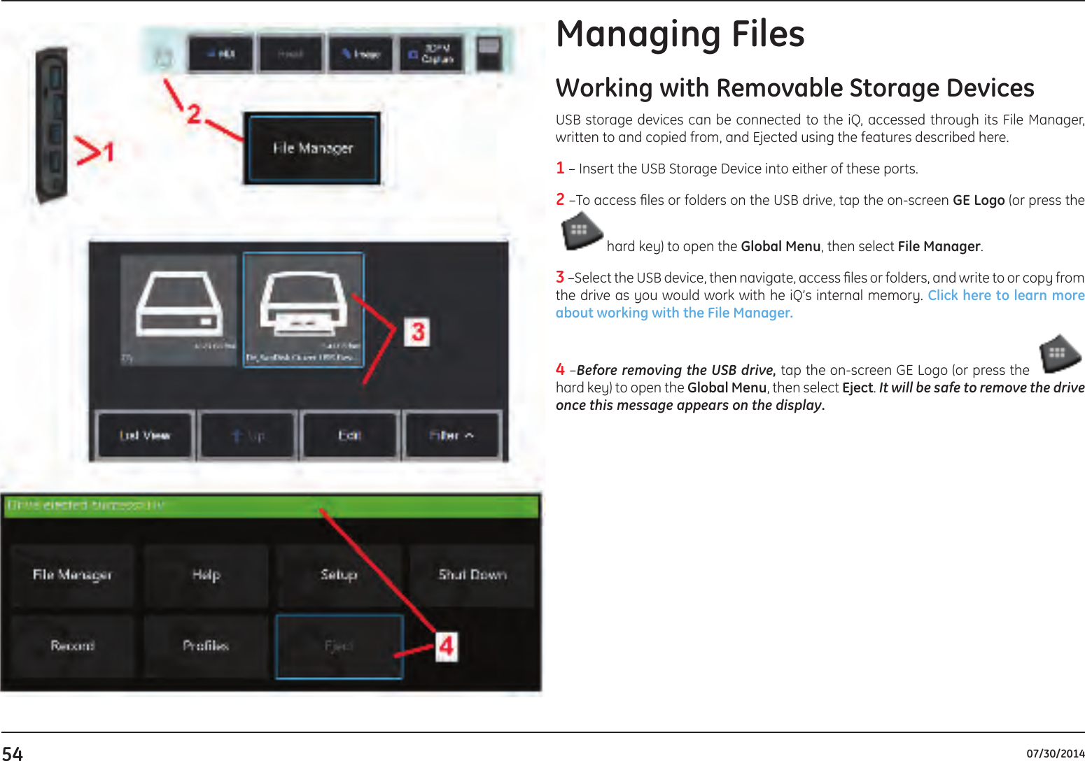
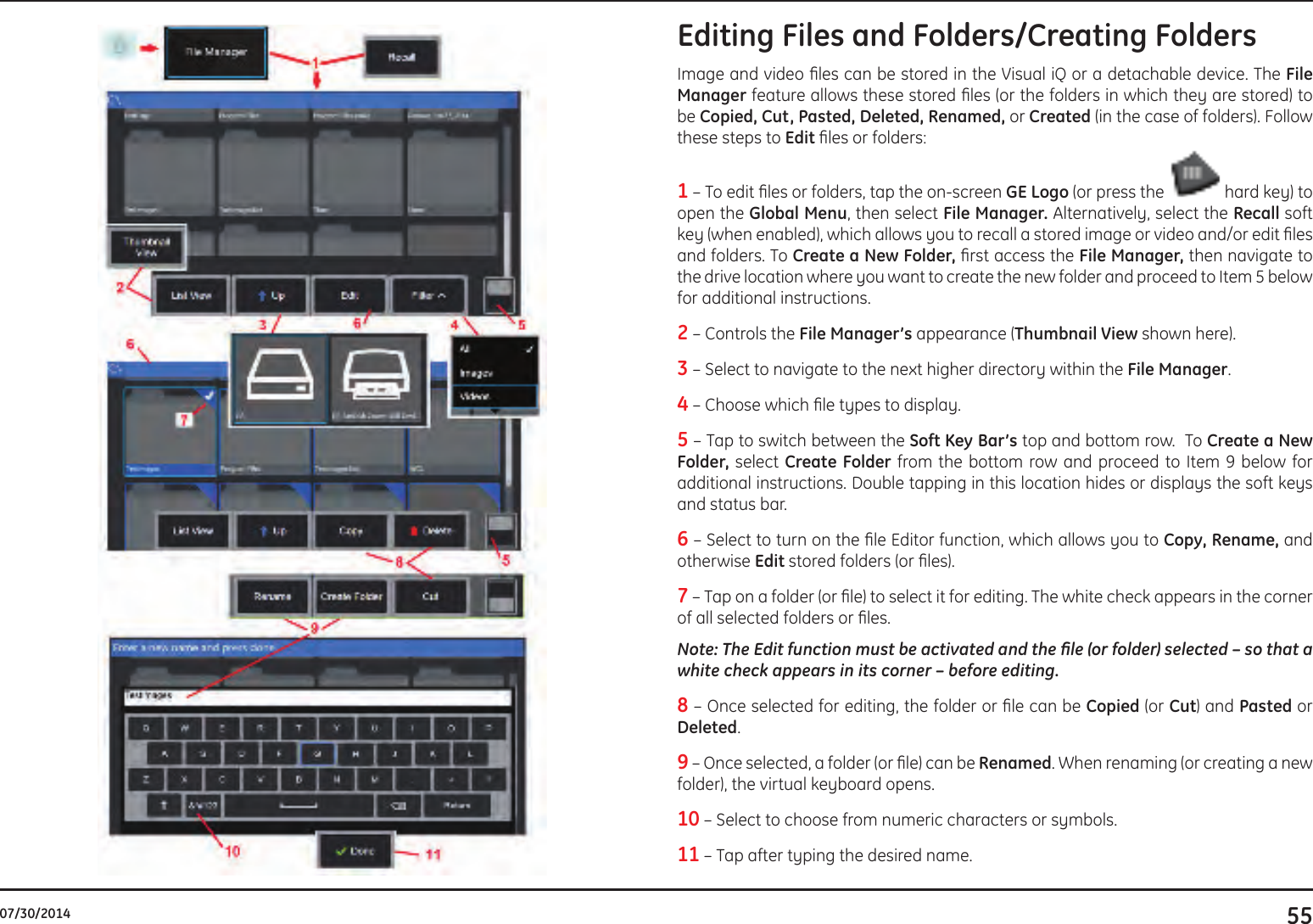
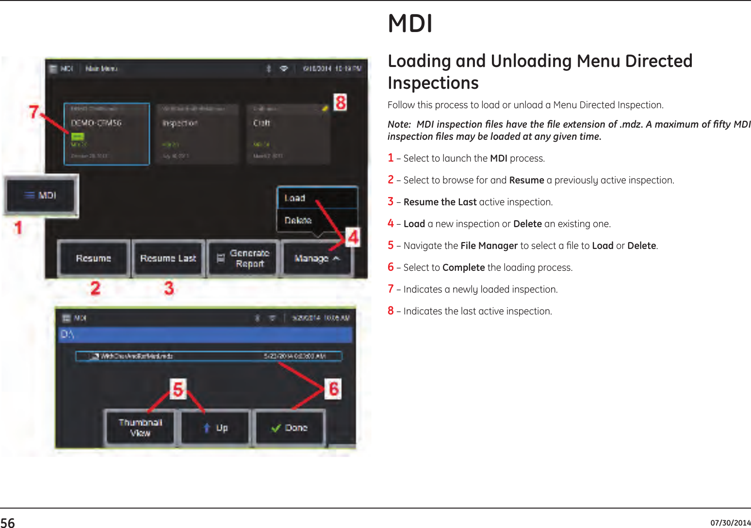
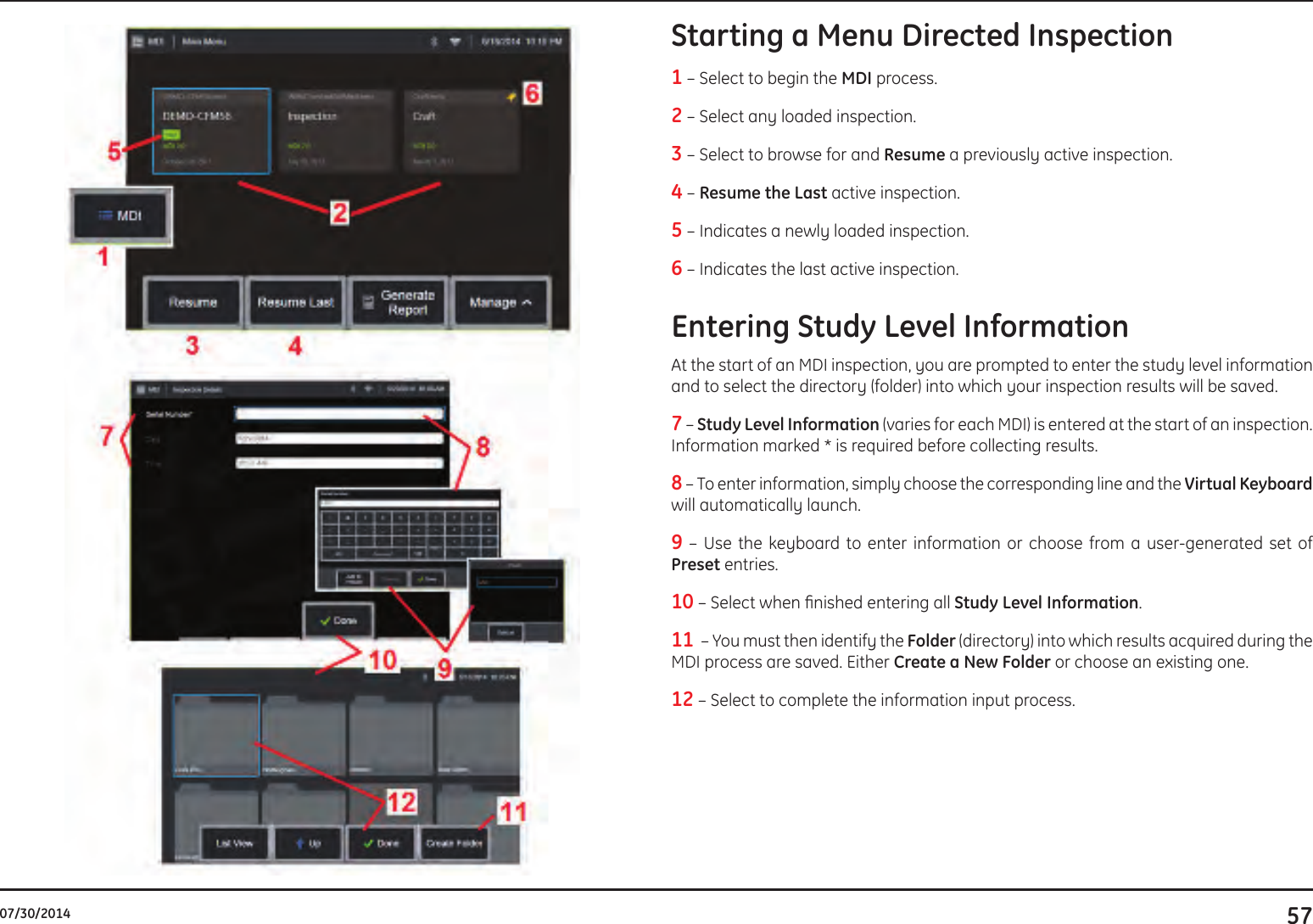
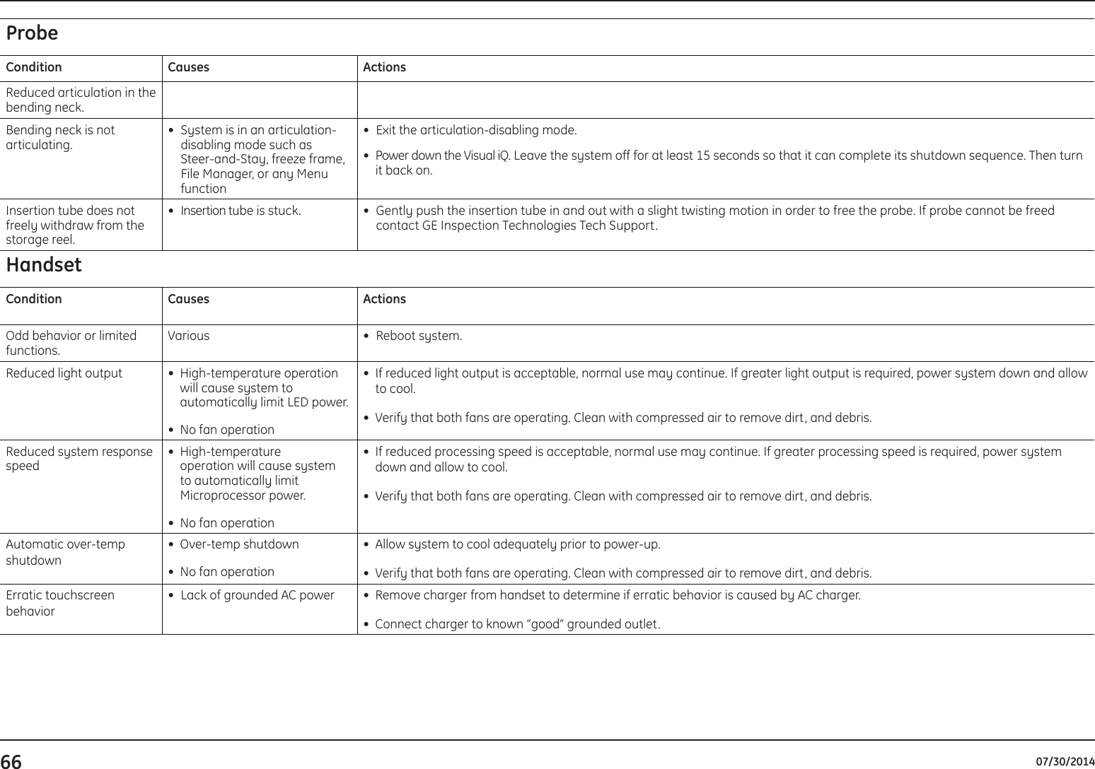
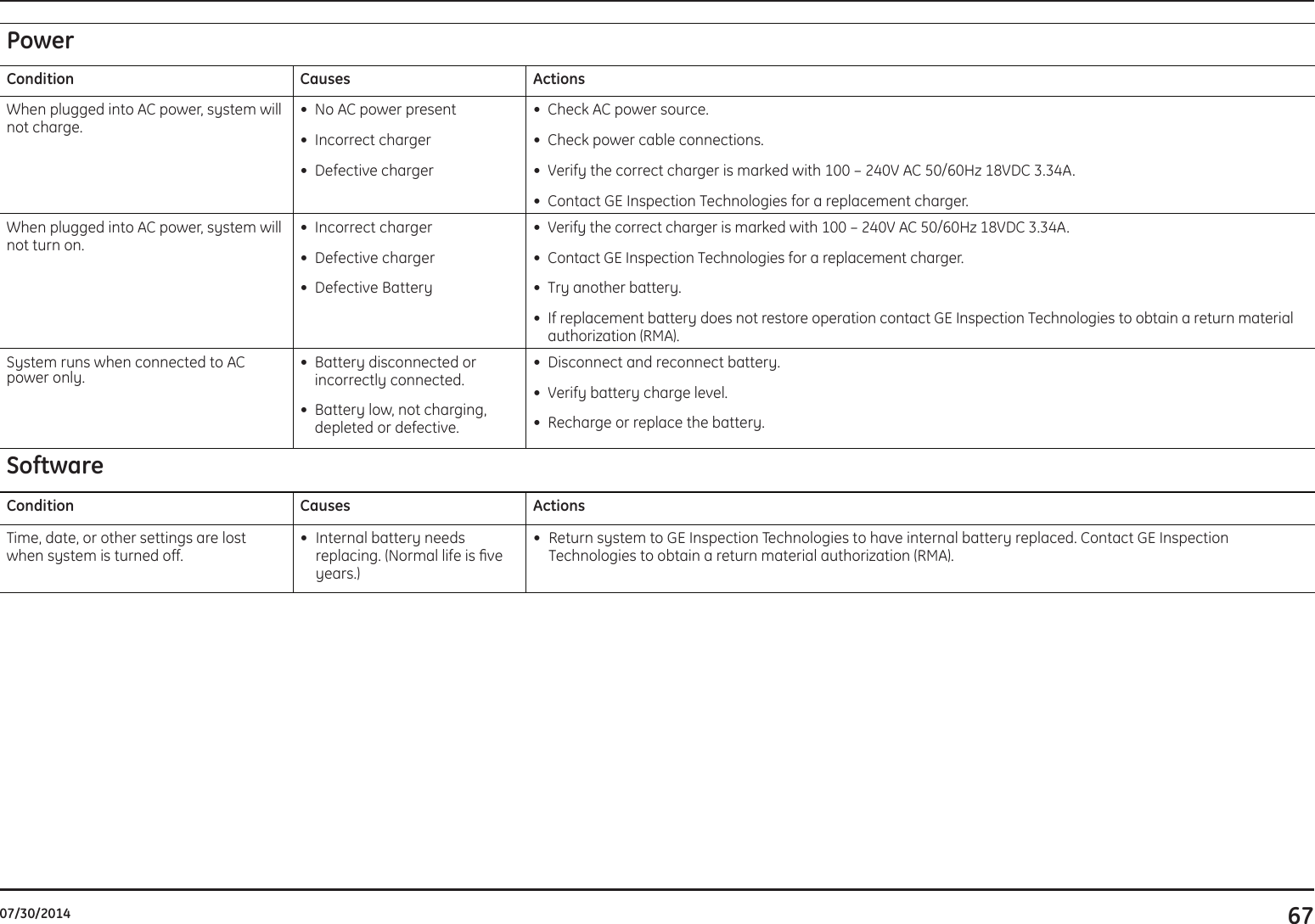
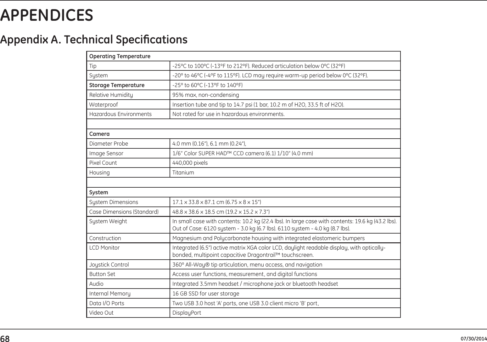
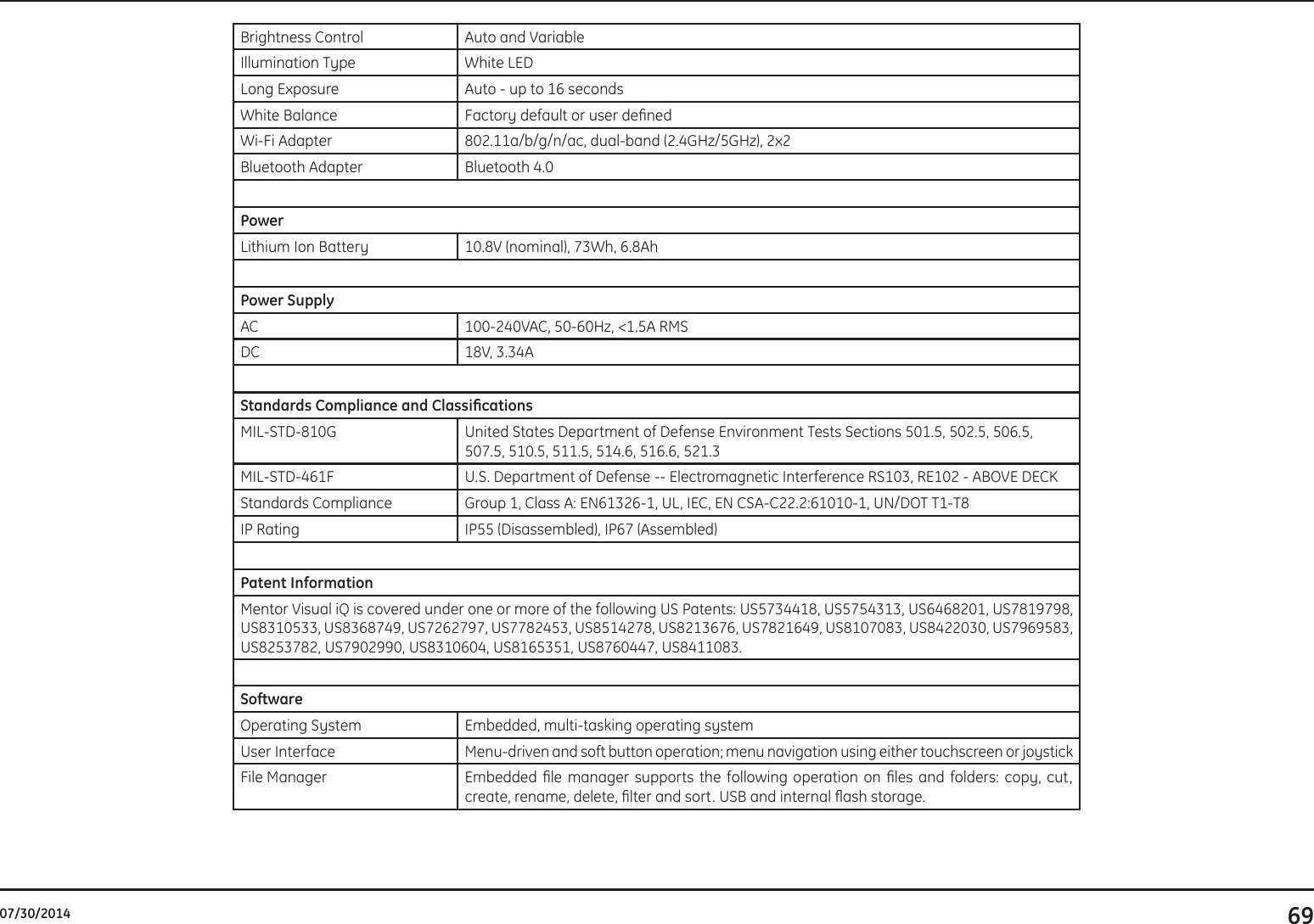
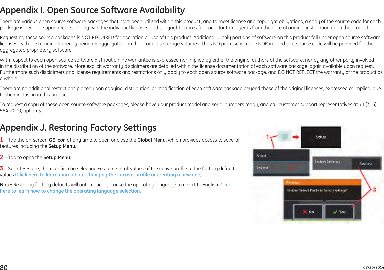
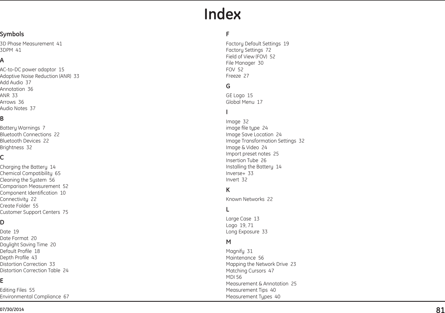
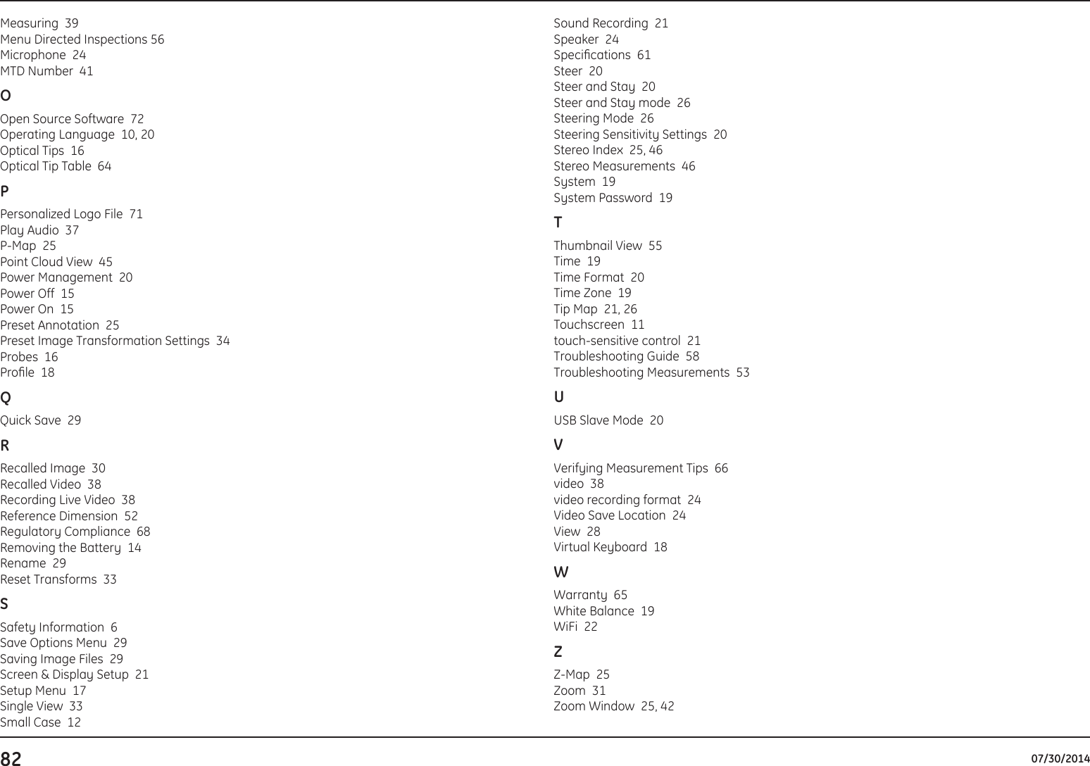
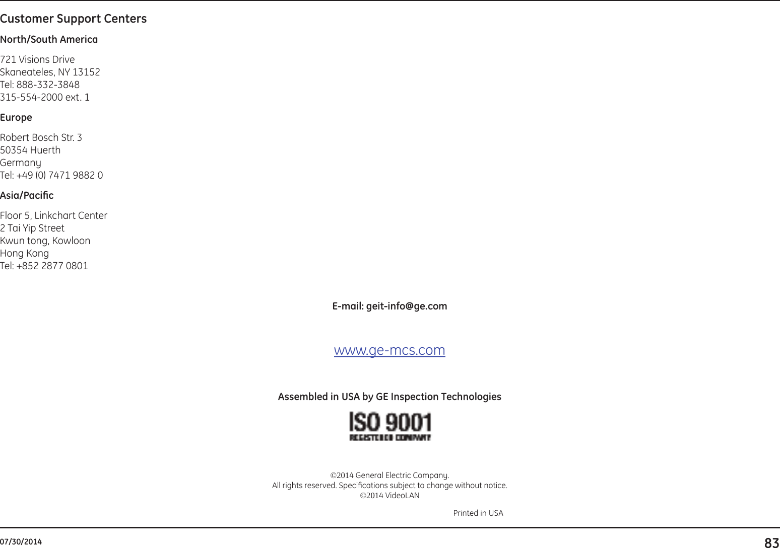
User manual
User manual
Navigation menu
Upload a User Manual
Namespaces
Wiki Guide
HTML
PDF
Info
Views
User Manual
Discussion / Help
Navigation