GE Inspection Technologies LP 7260H Model 7260HMW Wireless Network Adapter User Manual
GE Inspection Technologies, LP Model 7260HMW Wireless Network Adapter
Contents
- 1. Antenna specification
- 2. User manual
User manual

1
07/30/2014
Visual iQ VideoProbe
User’s Manual
MVIQAMANUAL Rev. B
Mentor

207/30/2014

3
07/30/2014
Table of Contents
Introduction 4
About this Manual 4
Getting Help 4
System Overview 4
Safety Information 6
Informations sur la sécurité 8
Start Up 10
ComponentIdentication 10
Touchscreen and Keys – Dual Control Systems 11
Unpacking, Assembling, and Powering the Visual iQ 12
Unpacking and Putting Away the System (Small Case) 12
Unpacking and Putting Away the System (Large Case) 13
About the Battery 14
Supplying Power to the Visual iQ 15
PoweringtheVisualiQOnandO 15
Changing Probes and Optical Tips 16
Setting Up the Visual iQ Operating System 17
WorkingwithProles 18
System Setup 19
Screen & Display Setup 21
Connectivity Setup (WiFi, Bluetooth, PCs, and Networks) 22
Image & Video Setup 24
Measurement & Annotation Setup 25
Capturing and Adjusting Images 26
Steering the Probe 26
Freezing the Image 27
Selecting a View 28
Saving Image Files 29
Working with a Recalled Image 30
Zoom to Magnify 31
Image Transformation Settings 32
Working with Preset Image Transformation Settings 34
Working with a Split Screen 35
Annotating with Text and Arrows 36
Adding Audio Notes to an Image 37
Working with Video 38
Recording Live Video 38
Working with a Recalled Video 38
Measuring Features and Indications 39
3D Phase Measurements (3DPM) 41
Stereo Measurements 46
Comparison Measurements 52
Troubleshooting Measurements 53
Managing Files 54
Working with Removable Storage Devices 54
Editing Files and Folders/Creating Folders 55
MDI 56
Loading and Unloading Menu Directed Inspections 56
Starting a Menu Directed Inspection 57
Entering Study Level Information 57
Selecting an Inspection Point 58
Saving an Image or Video in an MDI Inspection 59
Viewing Reference Material 60
Stopping and Resuming an Inspection 60
Generating an MDI Report 61
Customizing an MDI Report 62
Maintenance and Troubleshooting 63
Inspecting and Cleaning the System 63
Troubleshooting Guide 65
Appendices 68
AppendixA.TechnicalSpecications 68
Appendix B. Optical Tip Table 71
Appendix C. Chemical Compatibility 72
Appendix D. Warranty 72
Appendix E. Verifying Measurement Tips 73
Appendix F. Environmental Compliance 74
Appendix G. Regulatory Compliance 75
Appendix H. Creating a Personalized Logo File 79
Appendix I. Open Source Software Availability 80
Appendix J. Restoring Factory Settings 80
Index 81

407/30/2014
Introduction
About this Manual
This manual and the related equipment is intended for visual inspection technicians with a basic understanding of inspection principles and practices, and who are familiar with
basic computer operations, but who may not have experience with a video borescope system.
The manual contains safety, compliance, and basic operating and maintenance instructions for the Visual iQ VideoProbe™ system.
To ensure operator safety, please read and understand this manual prior to using the system.
Getting Help
For additional assistance, go to www.ge-mcs.com for a complete listing of contact information. Technical Support contact information follows:
Global Phone: 1-866-243-2638
Email: ITTechSupport@GE.com
Website: http://www.geittechsupport.com
System Overview
The rugged and dependable Mentor Visual iQ® system is an advanced exible video borescope used for remote visual inspection.
Working through access passages, the Visual iQ system delivers high-resolution images of internal details of turbine engines, airframes, automotive engines, piping, vessels, wind-
turbine gear boxes, underwater structures, etc.
The probe’s beroptic bundle illuminates the inspection area with light generated by an advanced Light Engine in the probe. At the end of the probe, a miniature camera assembly
converts the image into an electronic image, and sends it back through the probe. The system displays the image on the handset. No focusing is required, because the Visual iQ
system contains a xed-focus optical system with a large depth of eld.
Measurement capabilities allow your system to analyze and measure indications and features.
The Visual iQ system is compatible with USB thumb drives, USB keyboards, USB portable drives, and most other USB-based storage devices.
With our QuickChange™ interchangeable probes, you can quickly recongure the system for maximum productivity.

5
07/30/2014
Standard Equipment
Visual iQ
2-hour Li-Ion Battery
Visual iQ Storage Case
AC Adapter/Battery Charger
Optical Tip Storage Case
USB Thumbdrive Containing Documentation, including User's Manual
Safety and Essential Use Hard Copy
Quickstart Card
Optional Accessories
Display Port Video Cable
Insertion Tube Gripper
Insertion Tube Rigidizer
Handset Holder
Headset (wired or wireless)
Cables
Belt Clip
Keyboard (wired or wireless)
Optical Tips
Measuring Optical Tips
Mini-Magic Arm Clamp Kit
Magic Arm Kit
External Monitor
Large Visual iQ Case
Optional Software
Menu Directed Inspection (MDI)—Intelligent le naming, image management, and post-
inspection reporting.
Inspection Manager (Re-measurement PC Application)

607/30/2014
Safety Information
Note: Before using or servicing the system, read and understand the following safety information.
Symbols and Terms
The following symbols appear on the product: , . See accompanying documentation.
General Warnings
The following warning statements apply to use of the system in general. Warning statements that apply specically to particular procedures appear in the corresponding
sections of the manual.
Do not allow the conductive insertion tube, system or its working tools to come in direct contact with any voltage or current source. Prevent all contact with live electrical
conductors or terminals. Damage to the equipment and/or electrical shock to the operator may result.
Do not use this system in explosive environments.
USE PROPERLY. Using any piece of this equipment in a manner not specied by the manufacturer may impair the product’s ability to protect the user from harm.
General Cautions
The following caution statements apply to use of the Visual iQ device in general. Caution statements that apply specically to particular procedures appear in the corresponding
sections of the manual.
Before using the camera system, install an optical tip or the head guard, which prevents damage to the tip-attachment mechanism. Keep the head guard on whenever no
optical tip is in place.
Handle the Probe Carefully: Keep the insertion tube away from sharp objects that might penetrate its outer sheath. Keep the whole insertion tube as straight as possible during
operation; loops or bends anywhere in the tube decrease its ability to steer the probe tip. Avoid bending the insertion tube sharply.
Note: Always use the Home function to straighten the bending neck before withdrawing insertion tube from an inspection area or putting probe away. Never pull, twist, or
straighten the bending neck by hand; internal damage may result. At the rst sign of damage, return the probe for repair.
Certain substances may damage the probe. For a list of substances that are safe for the probe, see “Chemical Compatibility” in the Appendix.

7
07/30/2014
Battery Warnings
Only use the battery and power supply specied for use with the system. Before use, thoroughly review the instructions in this manual for the battery and battery charger to
fully understand the information contained in them, and observe the instructions during use.
WARNING
• Do not place the battery in re or exceed the battery operating temperature.
• Do not pierce the battery with nails, strike the battery with a hammer, step on the battery, or otherwise subject it to strong impacts or shocks.
• Do not expose the battery to water or salt water, or allow the battery to get wet (IP55 – Disassembled, IP67 – Assembled).
• Do not disassemble or modify the battery.
• The instrument contains a Lithium Ion battery and magnesium in its case. Should the instrument be involved in a re, use an extinguisher approved for use on electrical and
ammable metal res. Water must not be used.
Battery Communication Error: Exists when the Visual iQ shows this message on the display. If the problem persists, please contact your nearest customer support
center.
Using the battery outside its recommended operating range will result in degradation of the performance and service life. When storing the battery, be sure to remove it from
the handset.
Recommended ambient temperature range for Li-ion battery operation:
Discharge (when using the instrument): -20°C to 46°C
Recharging: 0°C to 40°C
Storage: -25°C to +60°C
807/30/2014
Informations sur la sécurité
Remarque: avant l’utilisation ou l’entretien du système, vous devez lire et comprendre les informations de sécurité qui suivent.
Symboles et termes employés
Les symboles suivants sont apposés sur le produit: , . Voir la documentation jointe.
Avertissements généraux
Les avertissements suivants s’appliquent à l’utilisation du système en général. Les avertissements qui s’appliquent spéci quement à des procédures particulières sont indiqués
dans les sections correspondantes de ce manuel.
Le système Visual iQ et les outils de travail qui l’accompagnent ne doivent jamais entrer en contact direct avec une source de tension ou de courant. Évitez tout contact
avec des conducteurs ou des bornes électriques sous tension. L’équipement risquerait d’être endommagé, ou l’opérateur de subir un choc électrique.
N’utilisez pas ce système dans un environnement à risque d’explosion.
UTILISER CORRECTEMENT. Si un élément de cet équipement est utilisé d’une manière non indiquée par le fabricant, l’utilisateur peut ne plus être protégé des risques de
blessure.
Mentions générales « Attention »
Les mentions « Attention » qui suivent s’appliquent à l’utilisation de l’appareil Visual iQ en général. Les mentions « Attention » qui s’appliquent spéci quement à des procédures
particulières sont indiquées dans les sections correspondantes du manuel.
MANIPULER LA SONDE AVEC PRÉCAUTION. Maintenez la gaine de la sonde à l’écart d’objets pointus ou tranchants qui risqueraient de traverser son fourreau. Maintenez toute
la gaine aussi droite que possible pendant l’utilisation : en cas de boucle ou de courbure, il est plus dif cile de piloter le bout de la sonde. Évitez de trop courber la gaine.
Remarque : utilisez toujours le bouton de rangement pour redresser le béquillage avant de rétracter la gaine de la zone d’inspection ou de ranger la sonde. Ne manipulez
jamais le béquillage à la main pour le tirer, le courber ou le redresser : vous risqueriez de l’endommager à l’intérieur. Envoyez la sonde en réparation au premier signe
d’endommagement.
Certaines substances risquent d’endommager la sonde. Pour consulterla liste des substances sans danger pour la sonde, voir Compatibilité Chimique en annexe.
L’appareil comporte une batterie lithium ion et du magnésium à l’intérieur de son boîtier. En cas d’incendie de l’appareil, servez-vous d’un extincteur agréé pour une utilisation
sur les incendies électriques et les métaux inammables. En aucun cas, n’utilisez de l’eau.

9
07/30/2014
Avertissements liés à la batterie
Utilisez uniquement la batterie et l’alimentation spéci ées pour être utilisées avec le système Visual iQ. Avant utilisation, lisez attentivement les instructions contenues dans ce
manuel relatives à la batterie et au chargeur de batterie pour bien les comprendre, et respectez ces instructions pendant l’utilisation de l’appareil.
AVERTISSEMENT
• Ne jetez pas la batterie au feu et ne dépassez pas sa temperature de fonctionnement.
• Ne percez pas la batterie avec des clous, ne la frappez pas avec un marteau, ne marchez pas dessus et ne la soumettez pas à des impacts ou des chocs violents.
• N’exposez pas la batterie à l’eau douce ou salée, et évitez de la mouiller.
• Ne désassemblez pas la batterie et ne la modi ez pas.
Erreur de communication de la batterie. Veuillez contacter le Service clientèle au numéro +1 315 554 2000.
L’utilisation de la batterie en dehors de la plage de fonctionnement recommandée entraînerait une dégradation de ses performances et de sa longévité. Lorsque vous stockez la
batterie, veillez à la retirer de sa base.
Plage de température recommandée pour le fonctionnement de la batterie Lithium-Ion.
Décharge (à l’utilisation de l’appareil) : -20°C à +46°C Recharge , 0°C à +40°C Stockage, -25°C à +60°C
10 07/30/2014
Start Up
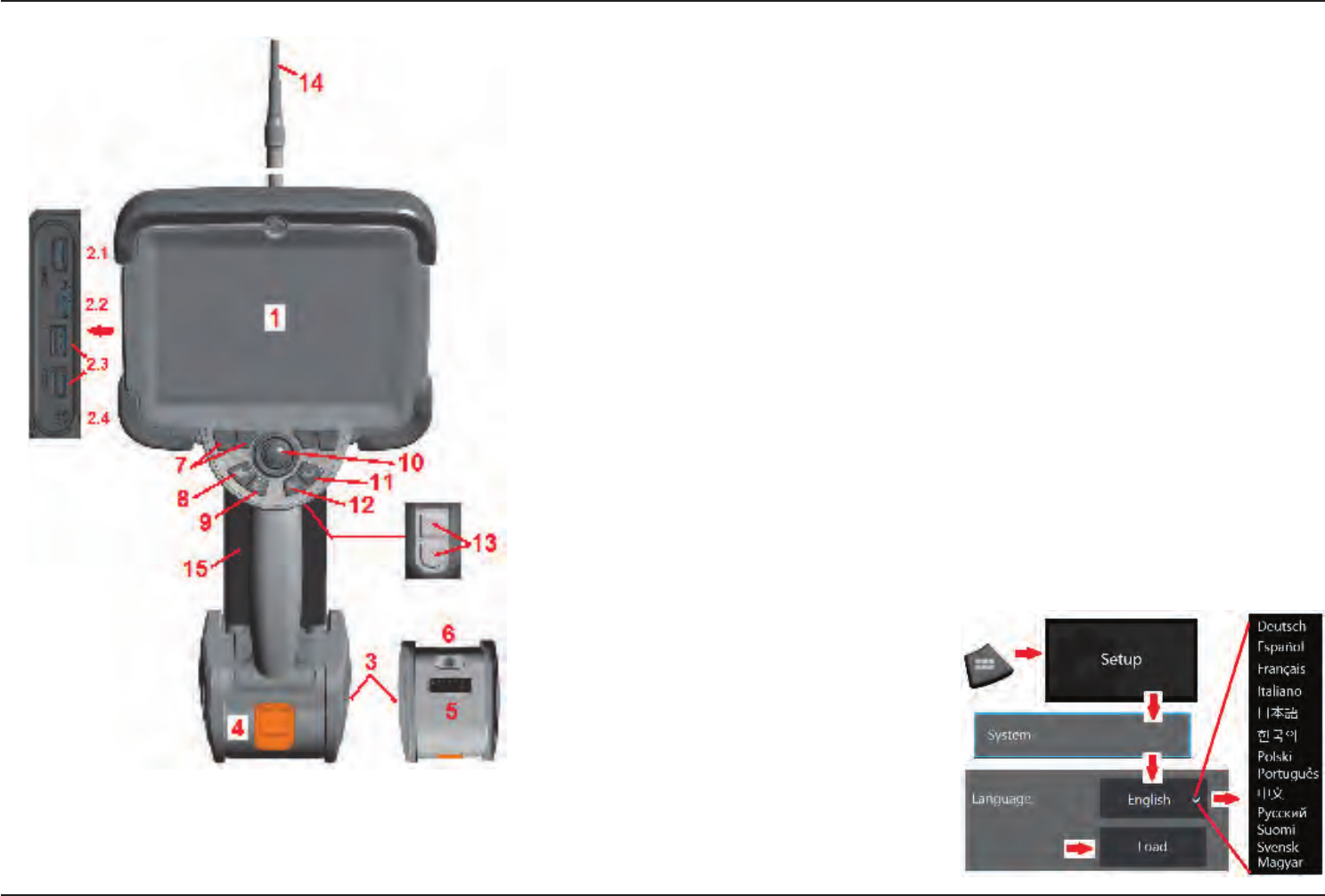
ComponentIdentication
1 – LCD Touchscreen
2 – DisplayPort Output (2.1), USB 3.0 Client Micro B Port (2.2), Two USB 3.0 Host Type A
Ports (2.3), 3.5 mm Headset/Microphone Jack (2.4).
3 – Two-hour Lithium Ion Battery
4 – Battery Release Button
5 – Battery Charge Indicator
6 – AC Adaptor Input
7 – Function (or Soft) Keys (four total)
8 – Back Button: short press moves back one screen, long press moves to live screen. This also serves
as the POWER ON button.
9 – Save Button: short press launches a Quick Save, long press opens or closes the Save Options Menu.
10 – Joystick Controls Articulation and Menu Navigation (push the joystick left/right/up/down to navigate
menus and sub-menus).
11 – Enter Button: short press toggles between frozen and live frames and selects Done / Accept, a
long press performs a 3DPM Capture.
12 – Menu Button: short press opens or closes the Global Menu, long press toggles between rst and
second level soft button rows.
Note: Follow the selection sequence shown here to
navigate the Global Menu and select the Operating
Language.
13 – Trigger Button 1 (Upper): provides the same
function as the Enter Button. Trigger Button 2 (Lower):
short press toggles articulation mode between steer-
and-stay and steering modes. When in steer-and-
stay mode, a Lock icon appears. Long press returns
the articulation system to the neutral (home) position.
14 – Insertion Tube/Camera assembly
15 – Interchangeable VideoProbe (Note: Includes
Insertion Tube/Camera assembly)
11
07/30/2014
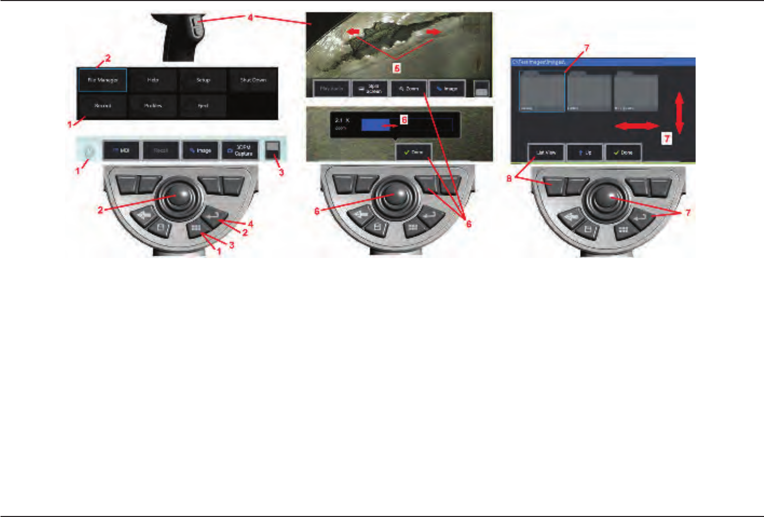
Touchscreen and Keys – Dual Control Systems
Most functions can be accomplished using the touchscreen or with a combination of
key presses and joystick movements. The following examples illustrate various control
techniques that can be used on most Visual iQ display screens.
1 – Touch the lower left corner of the display screen (typically contains the GE Logo) or
short-press the Menu key to open the Global Menu.
2 – The selected item in any menu or list is identied by this blue outline. Tap the display
screen to select another item or to launch the selected item. Alternatively, use the joystick
to select another item by moving the blue cursor, then short-press the Enter key to
launch. Note that a short press of the Enter key accepts or launches most selected
choices or actions.
3 – Tap the display to toggle between the upper and lower softkey bar (double-tap to
hide or show the softkey and status bars). Alternatively, long-press the Menu key to
switch between the upper and lower softkey bars.
4 – Tap anywhere on a displayed Live Image to freeze and unfreeze it. Alternatively, short-
press either the Enter key or the Upper Trigger key to freeze and unfreeze a live display.
Note that the Upper Trigger key performs the identical functions as the Enter key.
5 – Position two ngers on the display screen and move them apart to zoom in on a
feature of the display (perform the opposite action to zoom out). Once zoomed (in a
frozen image), you can drag with your nger to change the displayed view.
6 – Select the Zoom function using either soft keys or the touch screen (all displayed
soft-key bar items can be selected either with the corresponding soft key or by tapping
the touch screen). Use the joystick to change the zoommagnicationbar (this and other
blue bars can also be adjusted by dragging them using the touch screen), then select
Done. Once zoomed, you can use the joystick to move the displayed view.
7 – When the File Manager screen appears, the selected le or folder is identied by this
blue outline. Tap the display screen to select another item or to launch the selected le
or open the selected folder. Note that you can also display additional items (or directly
access additional stored images) by simply swiping the display screen in any of the
directions shown. Alternatively, use the joystick to select another item by moving the
blue cursor, then short-press the Enter key to launch the le or open the folder.
8 – Select any feature in the Soft Key Bar by either touching that feature on the display
screen (in this case, touching the box containing the words List View) or pressing the
corresponding soft key.
12 07/30/2014
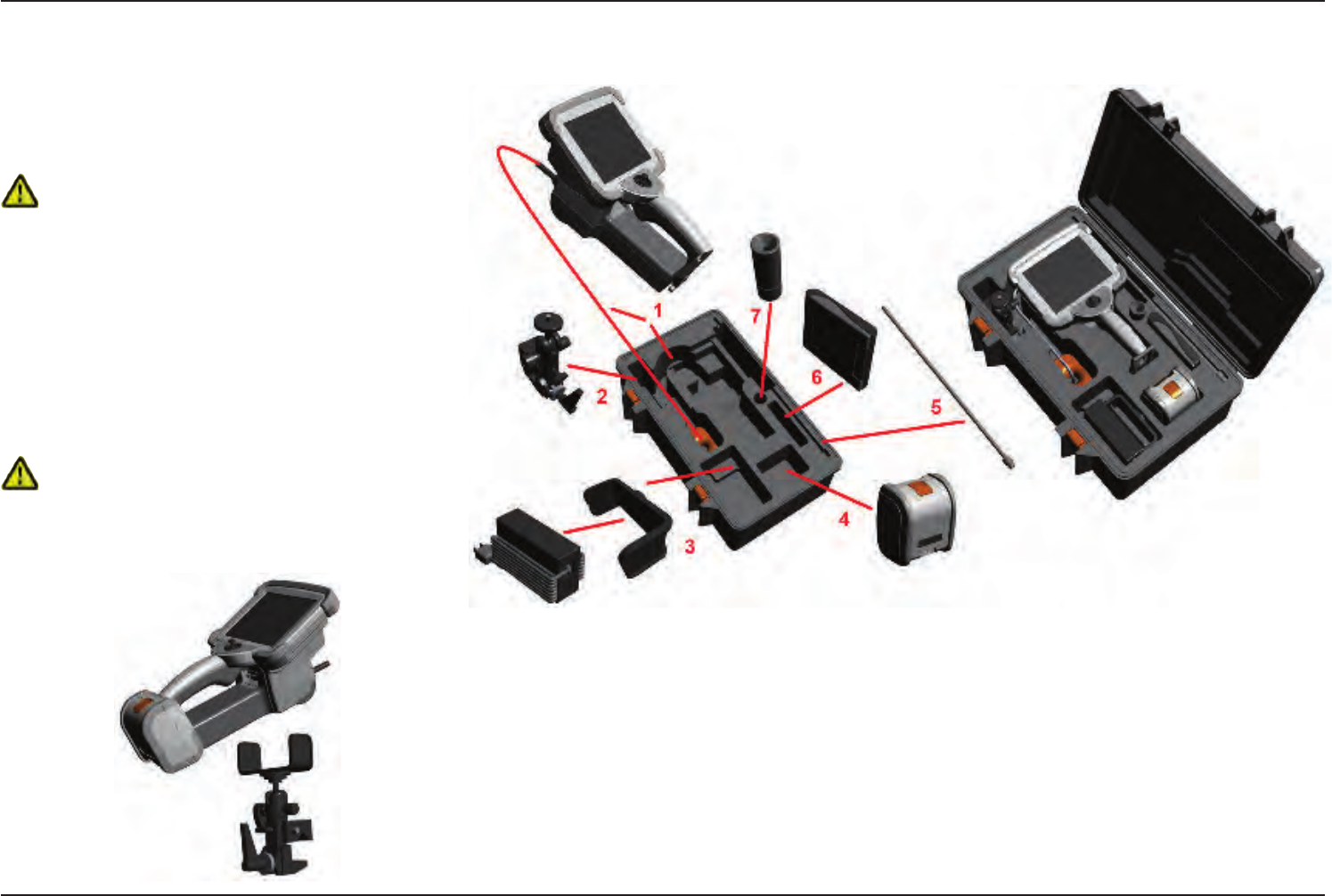
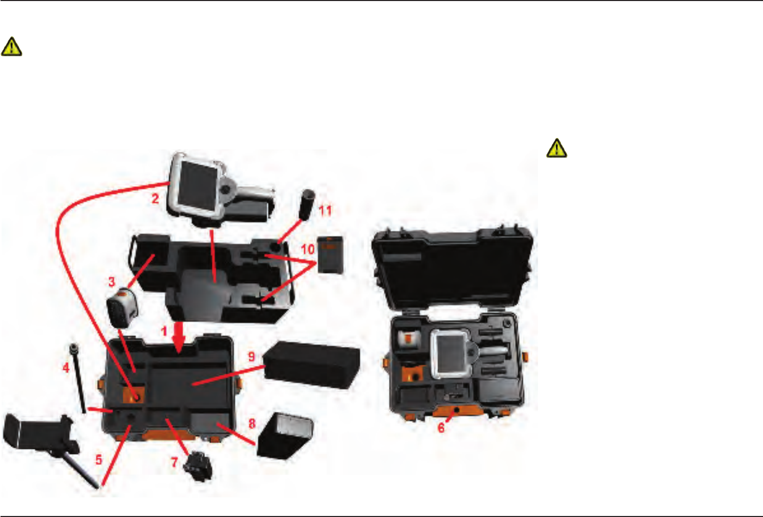
Unpacking, Assembling, and Powering the Visual iQ
Unpacking and Putting Away
the System (Small Case)
Caution: If you do not pack the system carefully, as
described here, damage might occur.
1 – The insertion tube (shown in red for clarity) is held in the
case’s internal storage reel, which is accessed through the
orange funnel shown here. Install the insertion tube before
installing the probe-and-handset assembly and remove it
after removing the probe-and-handset assembly. Be sure
to straighten any loops or twists in the insertion tube before
feeding it into the funnel. Note that the insertion tube’s rubber
Torsional Strain Relief base should be routed through the case’s
curved passage shown here.
Caution: Before using the camera system, install an
optical tip or the head guard, which prevents damage to
the tip-attachment mechanism. Keep the head guard on
whenever no optical tip is in place.
2 – Install clamp in the orientation shown here (clamp and mounting bracket assembly appears at left)
3 – Power supply / Battery Charger and Mounting Bracket are oriented and installed in this slot
4 – Battery must be removed prior to installing the iQ in the case.
5 – Rigidizer
6 – A case holding tips (or cleaning kit) ts in this slot.
7 – Gripper may be used alone, or with Rigidizer, to aid in orienting camera.
13
07/30/2014
Unpacking and Putting Away the System (Large Case)
Caution: If you do not pack the system carefully, as described here, damage might occur.
1 – Remove tray to access additional storage space.
2 – The insertion tube (shown in red for clarity) is held in the case’s internal storage reel, which is accessed through the orange funnel shown here. Install the insertion tube before
installing the probe-and-handset assembly and remove it after removing the probe-and-handset assembly. Be sure to straighten any loops or twists in the insertion tube before
feeding it into the funnel.
Caution: Before storing the insertion
tube, rst remove the optical tip and install the
head guard, which prevents damage to the tip
attachment mechanism. Keep the head guard on
whenever no optical tip is in place.
3 – Storage locations for two batteries. Battery must
be removed prior to installing the iQ in the case.
4 – Rigidizer
5 – Mounting bracket and post
6 – Mounting bracket post ts in this hole
7 – Power supply / Battery Charger installed in this
slot
8 – Extra Pod in case
9 – Extra VideoProbe in case
10 – Two cases holding tips and a cleaning kit t
in these slots.
11 – Gripper may be used alone, or with Rigidizer,
to aid in orienting camera.
14 07/30/2014
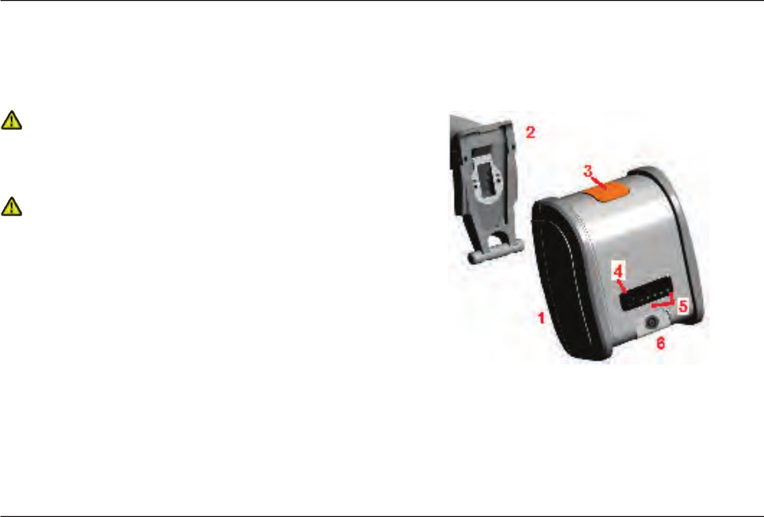
About the Battery
The Visual iQ is powered by a 10.8 V (nominal), 73 Wh, 6.8 Ah Lithium Ion battery.
Installing the Battery
Insert the battery into the handset. The battery is installed properly when the latching
mechanism is engaged.
Caution—Do not force the battery (1) into the handset (2), as damage may occur.
The battery is keyed and may only be installed in the proper orientation.
Removing the Battery
Press battery release button (3) to release the battery.
Caution—Do not remove the battery while the system is operating.
Battery Charge Level
Check the battery charge by pressing the battery symbol (4) on the front of the battery.
Each light (5) represents approximately 20% of the battery charge capacity.
Charging the Battery
Connect the DC output of the battery charger into the Visual iQ battery (6) and then
plug the included AC to DC power adaptor into a suitable AC power source. The LED
battery lights will illuminate according to the amount of charge attained. The system
may operate while charging.
Note: The battery may be charged while connected to an operating Visual iQ or while
disconnected from the iQ.
Note: When the battery is fully charged, the LED battery lights will turn off.
Note: Battery run time approximately equals battery charge time; therefore, a two hour
battery will take approximately two hours to charge. Charging time will be longer if the
battery is connected to an operating Visual iQ system while charging.
Note: All batteries are shipped with a partial charge. Batteries should be fully charged
prior to use.
15
07/30/2014
Supplying Power to the Visual iQ
The Visual iQ is powered by a 10.8 V (nominal), 73 Wh, 6.8 Ah Lithium Ion battery.
The battery is charged by connecting the power adaptor to the battery, then connecting
the supplied AC-to-DC power adaptor to a suitable (100-240 VAC, 50-60 Hz, <1.5 A rms)
AC power source. The power adaptor delivers to the battery 18 Volts at 3.34 Amps.
Note: When powering a system with an AC power source, connect the power plug to a
properly grounded source for reliable touchscreen operation.
PoweringtheVisualiQOnandO
System Power On
Press and hold until the unit turns on. The buttons and Liquid Crystal Display (LCD)
will light and begin the power-up sequence. After approximately 35 seconds, the system
screen will display live video and on-screen controls. The system is now ready for use.
Note: All batteries are shipped with a partial charge. Batteries should be fully charged
prior to use.
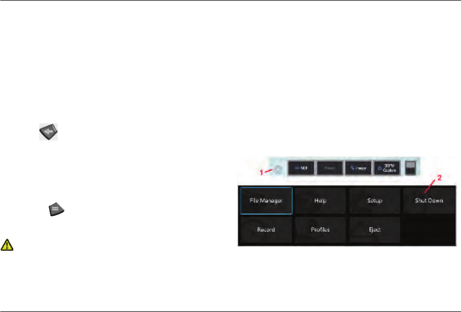
System PowerO
Touch the lower left corner of the display screen (which typically contains the on-screen
GE Logo (1) or the hard key at any time to open or close the Global Menu, which
provides access to several features including Shut Down (2). Select Shut Down to power
off the Visual iQ.
Caution—Do not power off the Visual iQ by removing its battery. Only remove
battery after powering off as described above.
16 07/30/2014
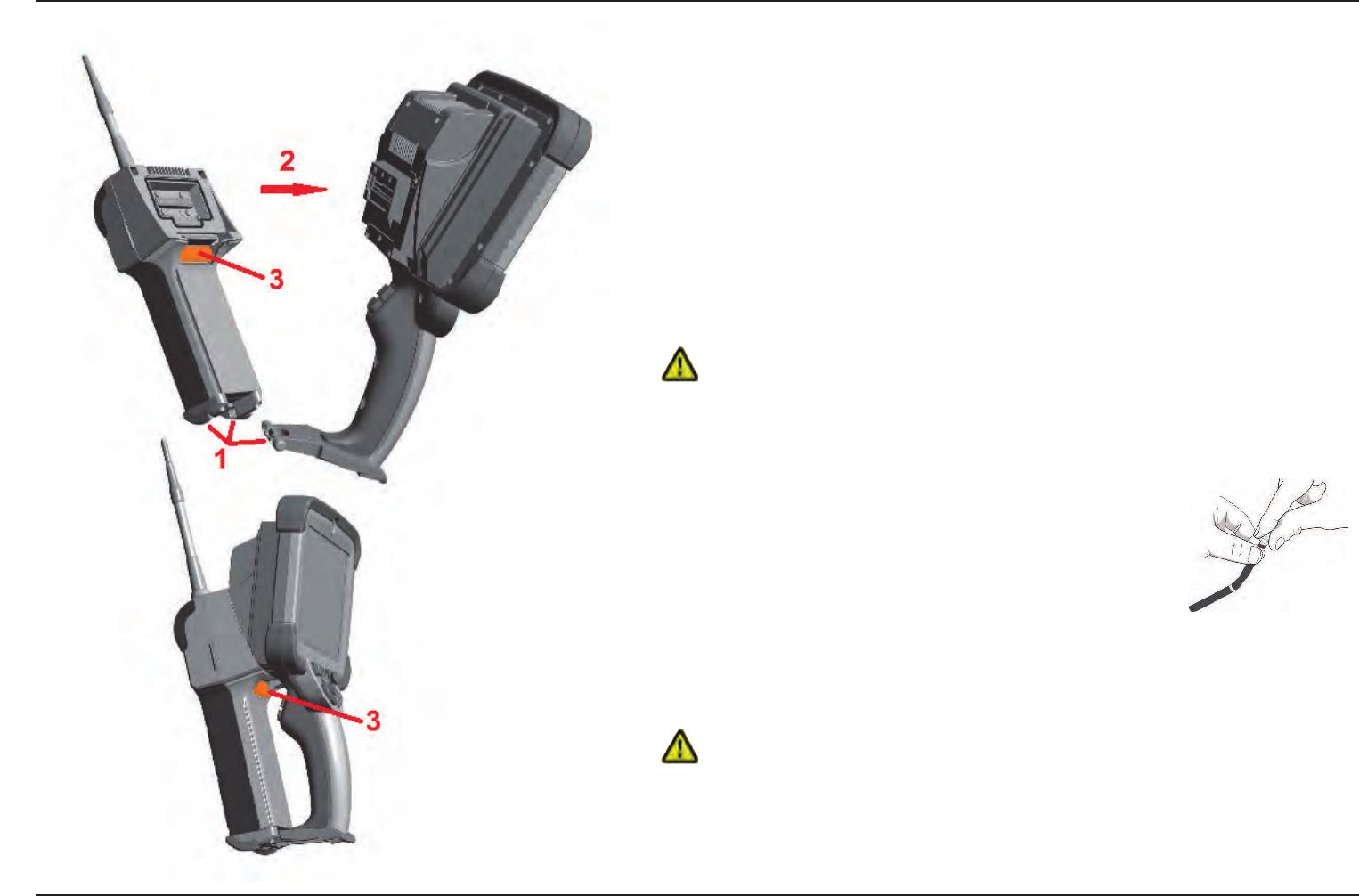
Changing Probes and Optical Tips
Attaching and Removing the Probe
To attach the probe to the handset:
1 – Insert the pin at the base of the handset into the mating groove at the bottom of the probe.
2 – Rotate the probe towards the back of the handset, applying enough pressure for the latching
mechanism to “click.”
To remove the probe from the handset:
3 – Press this latching-mechanic's release button to separate the probe and handset.
Changing the Optical Tip
Optical tips are threaded onto the probe with a double set of threads to prevent them from
falling into the inspection area. Each optical tip provides a unique depth of eld, eld of view,
and direction of view. For a list of available tips, see Appendix B – Optical Tip Table.
Caution—Use only nger pressure to remove or attach tips. Using force (including pliers
or other tools) might damage the bending neck. Take care not to cross the threads. To reduce
cross-threading risk: When installing a tip by hand (6.1mm & 8.4mm) or with an installation tool
(4mm), rotate the tip counter clockwise to level the threads before rotating clockwise to thread the
tip on the camera. Reverse the leveling process when removing tips.
To Remove an Optical Tip: Support the bending neck and head of
the probe with one hand, and with the other gently turn the optical
tip counterclockwise (be sure to use a tip tool when removing 4.0 mm
tips), Turn until the tip spins freely, indicating that it has cleared the
rst set of threads. Gently pull the tip away from probe and continue
turning counterclockwise, engaging the second set of threads. Turn
until you can remove it.
To Attach an Optical Tip: Verify that the optical tip and camera head threads are clean, then
grasp the head of the probe with one hand, and with the other gently turn the tip clockwise.
Turn until it spins freely, indicating that it has cleared the rst set of threads. Gently push the
tip in, then turn clockwise again, engaging the second set of threads. Turn until nger tight.
Caution—Do not over-tighten tips. Pull on the tip gently to verify that it is securely attached.
If the second set of threads does not engage, turn the tip slightly in a counterclockwise direction
to allow the threads to levelize.
Note: Measurement tips must be tightened rmly to ensure accuracy.
17
07/30/2014
Setting Up the Visual iQ
Operating System
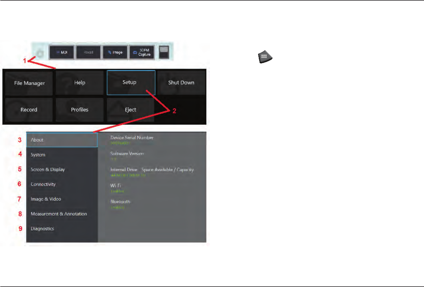
1 – Select the lower left corner of the display (which typically contains the on-screen
GE Logo) or the hard key at any time to open or close the Global Menu, which
provides access to several features including the Setup Menu.
2 – Tap to open the Setup Menu.
3 – Lists the device’s serial number, software version and describes the conguration
of its available features.
4 – Access to set a Password, Restore Defaults, adjust Date, Time, and operating
Language, and alter various other system settings. Click here to learn more about
the System Menu.
5 – Allows the user to turn various on-screen indicators on and off as well as adjust
display brightness. Click here to learn more about Display Setup.
6 – Allows the user to turn Wi-Fi and Bluetooth connections on and off as well as work
with networks and identify folders for le sharing. Click here to learn more about
Connectivity Settings.
7 – Allows the user to specify the default directories into which image les and videos
are stored. Also used to select image le type, video format, and sound-related settings.
Controls MDI Annotation and imports Distortion Correction Tables. Click here to learn
more about Image and Video Settings.
8 – Allows the user to set their preferred measurement units (inches vs. mm), manage
and verify measurement tips, and import and export preset annotations.
9 – Generates a Troubleshooting Log to be emailed to and evaluated by GE Technical
Support. If log generation is required, GE Technical Support will guide the user through
the process.
18 07/30/2014
WorkingwithProles
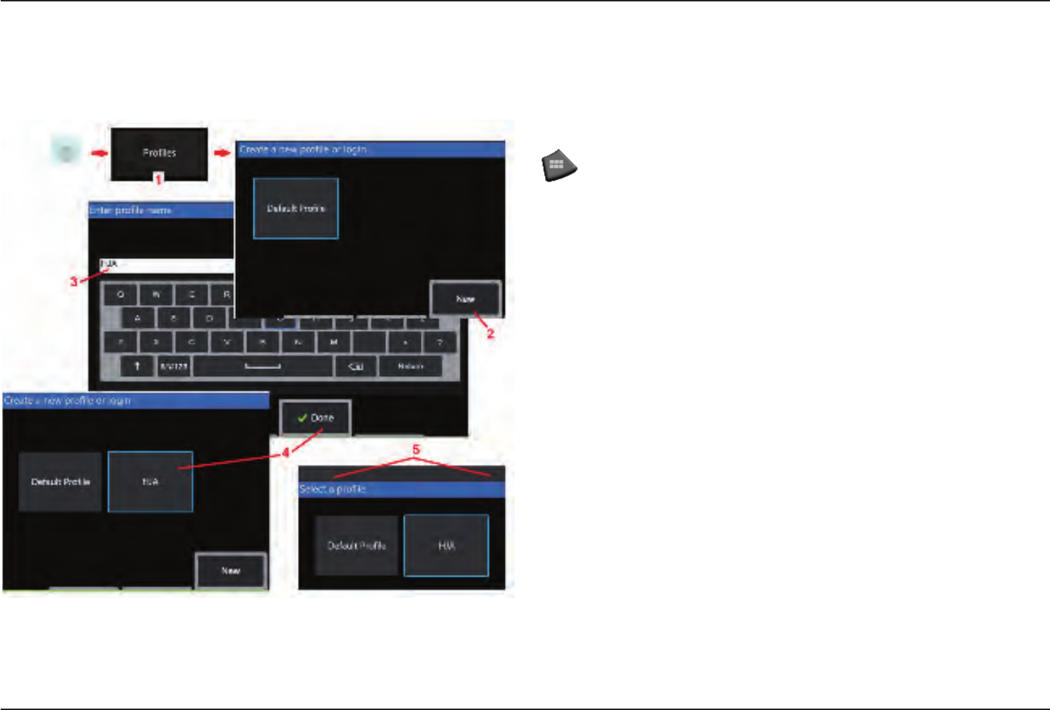
A Prole denes several parameter settings. As long as more than one prole is available,
(the Visual iQ is delivered with only a DefaultProle), the operator is asked to select a
Prole every time the system is powered on. Follow these instructions to create a new
prole or select an existing one.
1 – To create a New Prole, touch the lower left corner of the display (or press the
hard key) to open the Global Menu, then select Proles.
2 – In this case, the DefaultProle is active and it is the only one dened. Select New
to create a new prole.
3 – The Virtual Keyboard opens. Enter a Name for the new prole.
4 – After entering a name and clicking Done, the new prole is added to the list of available
proles. This prole includes the settings in place, at the time of its creation, for each of
the parameters listed below. Anytime the prole is reactivated, the system will apply the
settings associated with the activated prole. The parameters affected include:
System Settings Including:
Watermark Logo ON/OFF
Time Format
Date Format
Language
Power Management
USB Slave Mode
Steering Sensitivity
Screen & Display Settings – All Parameters
Connectivity Settings Including:
Wi-Fi on/off
Bluetooth on/off
Image & Video Settings – All parameters
except Distortion Correction Table
Measurement & Annotation Including:
Presets
Zoom Window
3DPM Mask
3DPM Save Format
Stereo Index
Stereo Index Minimum
Units
5 – Each time the Visual iQ is powered on, you’ll be asked to select from the list of
available proles. Selecting the Default Prole returns the settings for all prole-controlled
parameters to those specied by the default prole.
19
07/30/2014
System Setup
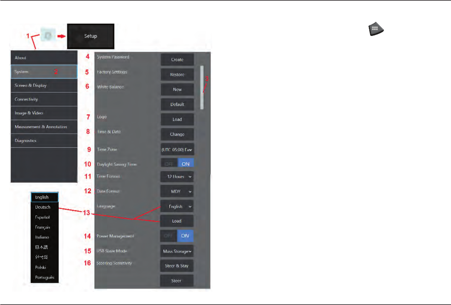
1 – Tap the on-screen GE Logo (or press the hard key) to open the
Global Menu, then open the Setup Menu.
2 – Select to alter the system-specic settings shown here.
3 – Drag your nger up or down the screen. This bar will move to show the current
position among the list of system-specic settings.
4 – Tap to open the virtual keyboard and create or change a System Password. Once
created, accessing the iQ’s operating sceens requires rst entering the password. This
password is for the entire system and is not associated with the active prole.
Note: Entering a password requires the DefaultProle be active.
5 – Select and follow the on-screen prompts to restore the active Prole to the Factory
Default Settings.
Executing a White Balance
A white balance corrects the color so that white appears white despite any slight hues
that may exist under the lighting conditions present when performed.
6 – Select New and follow the prompts to point probe at a white target or select Default
to restore factory color settings.
Loading a Logo
A logo can be loaded onto the display screen provided it is PNG le type (with dimensions
smaller than 140 x 140).
7 – Select Load, then navigate the instrument or an external drive to select any PNG le
type as the on-screen logo. Click here for more information on creating and loading
apersonalizedlogole.
Setting Date and Time
8 – Adjust Time and Date settings.
9 – Select the Time Zone in which you are operating.
20 07/30/2014
10 – Turing Daylight Saving Time to ON causes the system to automatically adjust the
time setting.
11 – Specify 12 or 24 hour Time Format.
12 – Specify DMY, YMD, or MDY as the Date Format.
Loading and Selecting the Operating Language
13 – Choose from the operating Languages currently available for use. Selecting Load
allows you to upload a new version of any of the existing translations available in the iQ.
Once selected, the File Manager screen allows you to navigate to the modied translation
le.
Other System Settings
14 – Setting Power Management to ON conserves battery power by putting the Visual iQ
into sleep mode after 10 minutes of inactivity. When in sleep mode, in which only the hard
keys remain lit, touching any key or the joystick returns the iQ to a fully powered state.
15 – Set the USB Slave Mode to Mass Storage or Disable. When set to Mass Storage,
a connected computer can work directly with les stored on the Visual iQ’s hard drive
for le management purposes. In this state, the iQ will not perform inspection functions.
When le management functions are complete, change setting to Disable to return
inspection functionality.
Steering Sensitivity Settings
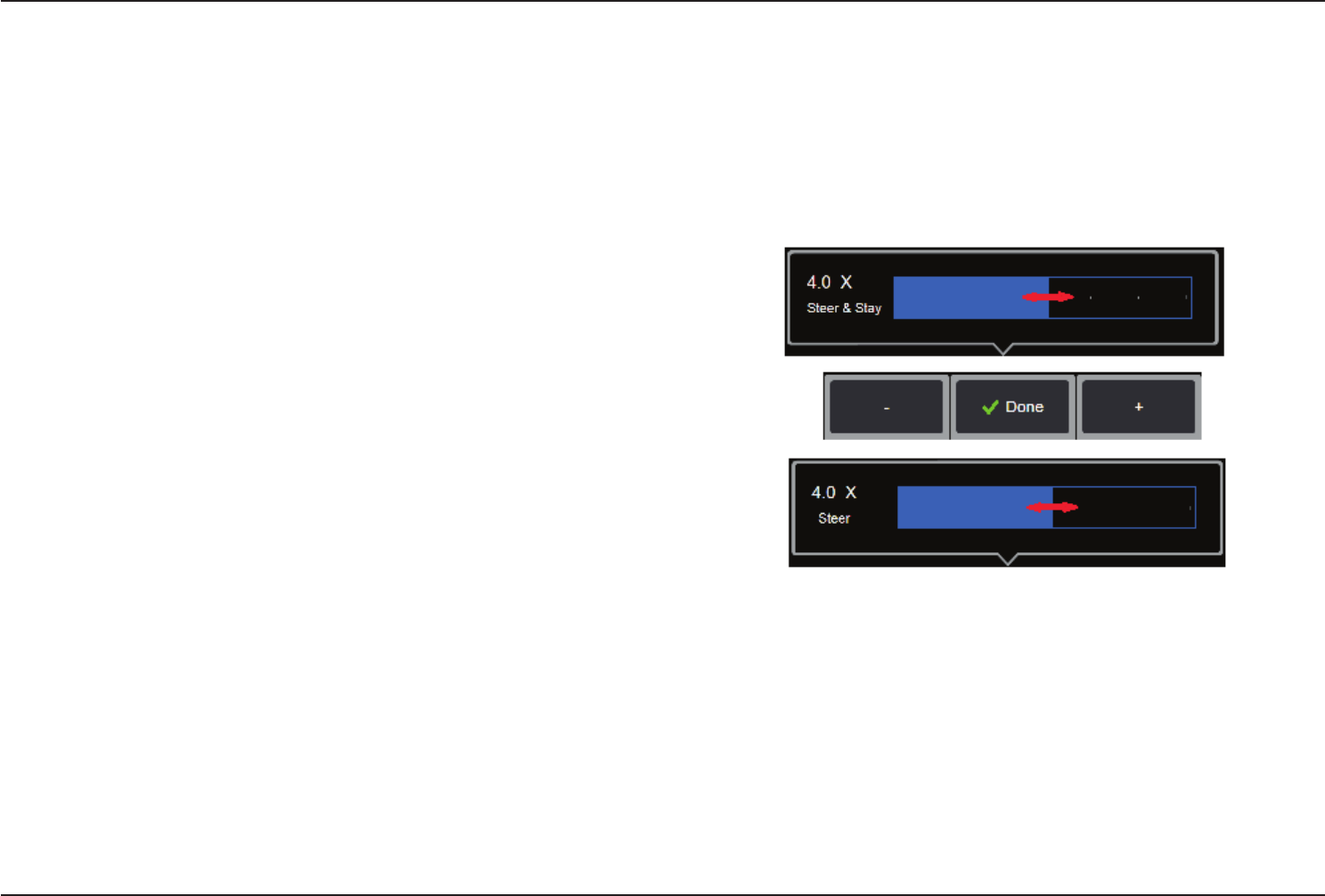
16 – The user can select from two probe steering modes: Steer or Steer and Stay™.
In either mode, the bending neck articulates to follow the joystick motion. The modes
differ in how they behave after the bending neck is positioned (click here to learn about
thedierencesbetweenthesemodes). Select either button shown here then drag the
setting bar to set the sensitivity of either Steer or Steer and Stay mode. The higher the
setting, the more the bending neck will articulate with a change in joystick position. For
instance, increasing the setting from 2.0 to 4.0 means that a similar joystick movement
will produce a greater amount of bending neck articulation.
21
07/30/2014
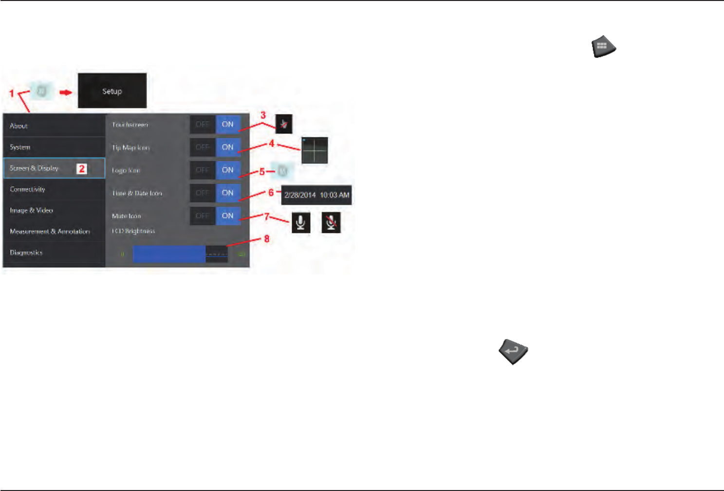
Screen & Display Setup
1 – Tap the on-screen GE Logo (or press the hard key) to open the
Global Menu, then open the Setup Menu.
2 – Select to alter the display-screen appearance and operation.
3 – Turn the display screen’s touch-sensitive control ON or OFF. Once turned OFF, the icon
shown here appears at the top of the display screen. Once disabled, use a combination
of joystick and hard key press to re-enable the touchscreen.
4 – The Tip Map (shown here) graphically represents the extent to which the optical
tip is articulated by positioning a bright dot at some distance from the crosshairs. The
closer the dot appears to the center of the crosshairs, the straighter the tip’s position.
5 – The customizable watermark shown here appears in the bottom left corner of the
display screen. Tapping this location opens the Global Menu. Turning this icon OFF
causes it to disappear while tapping in its former location still opens the menu.
6 – Turn the displayed date and time, which appears on the status bar at the display’s
upper right corner, ON or OFF.
7 – Select to turn the Sound Recording and/or Sound Recording Muted icons (shown
here) ON or OFF. These icons appear in the display’s bottom right corner when recording
video with an audio stream. Note that when these icons are visible (turned ON), selecting
the onscreen icon mutes or unmutes the sound recording.
8 – Control the display’s brightness by using your nger to drag this bar right or left (or
select with the joystick, press and then position with the joystick).
22 07/30/2014
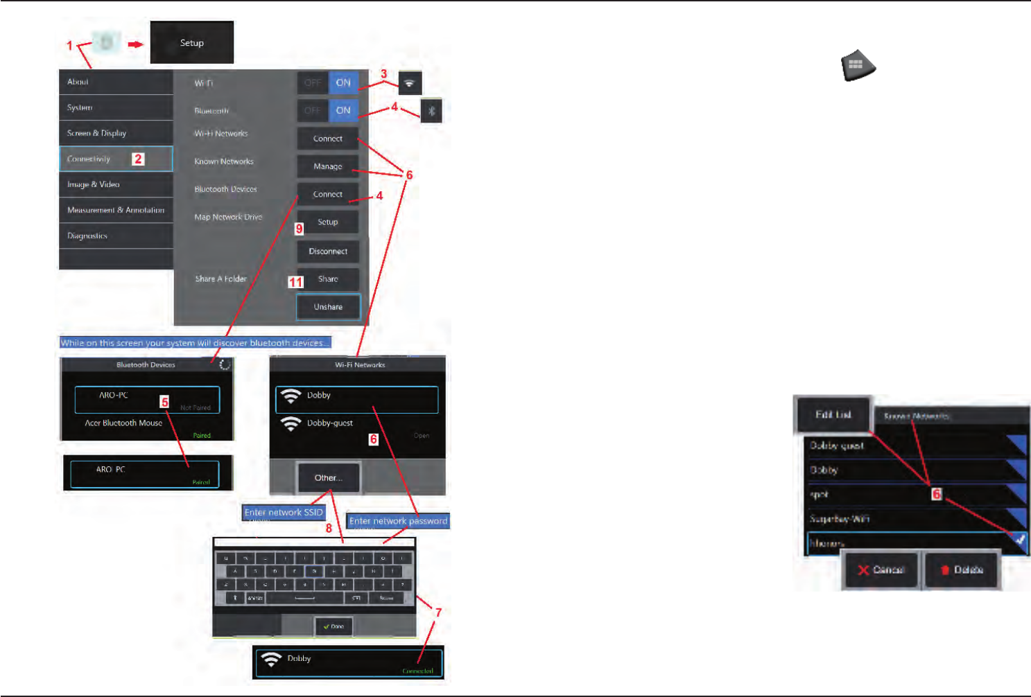
Connectivity Setup
1 – Tap the on-screen GE Logo (or press the hard key) to open the
Global Menu, then open the Setup Menu.
2 – Select to work with settings that control the connection of the Visual iQ to WiFi
networks and Bluetooth devices.
3 – Turn the WiFi connection ON or OFF. Once turned ON, the icon shown here appears
at the top of the display screen.
Making Bluetooth Connections
4 – Turn the Bluetooth connection ON or OFF. Once turned ON, the icon shown here
appears at the top of the display screen. The icon is gray if Bluetooth is ON or white
if Bluetooth is ON and paired with a device. Then, select Connect to display a list of
available Bluetooth Devices to which the iQ can connect.
5 – Available Bluetooth Devices that appear on this list can be paired with by simply
tapping the on-screen listing. When the device status switches from Not Paired to Paired,
it is in Bluetooth communication with the Visual iQ.
Working with WiFi
6 – Select Connect to display a list of
available WiFi networks to which the iQ
can connect. Tap the screen to select
an already known network from this
list. (Select Manage Known Networks
at any time to review the list of already-
recognized networks and/or Edit the list by
removing networks to which you no longer
wish to automatically connect). Once Edit
List is selected, tap the blue corner of any
network to delete it from the list.
7 – If prompted by the onscreen instructions, use the Virtual Keyboard to enter the
network’s password.
8 – Selecting Other allows you to enter the SSID of a hidden network not shown above.
23
07/30/2014
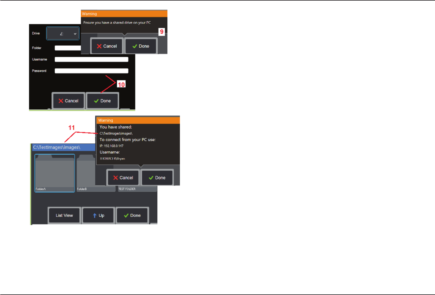
Mapping the Network Drive and Sharing Folders
9 – If you choose to give the Visual iQ’s File Manager access to a folder on a network-
connected computer, click on Setup (see above) to open the network-mapping process
shown here. Next, select Done to conrm that the network connected PC has at least
one folder identied for sharing.
10 – Enter the drive letter you wish to assign (in the Visual iQ’s File Manager) to the
shared folder, then input the complete path to the folder on the network-connected
PC. Following is an example of a complete path to insert in the Folder line: \\Device
Name\TestShare Folder. When the folder path and username/password (assuming it
is a password protected network) have been entered, click Done.
11 – To share one of the Visual iQ’s folders with a network-connected computer, click
on Setup (see above) to open the le-selecting process. The path in the blue bar shown
here identies the folder that will be shared. Next, select Done to display the Warning
statement listing the folder that will be shared, and select Done again to conrm that
the identied folder is the one you wish to share with a network-connected PC.
24 07/30/2014
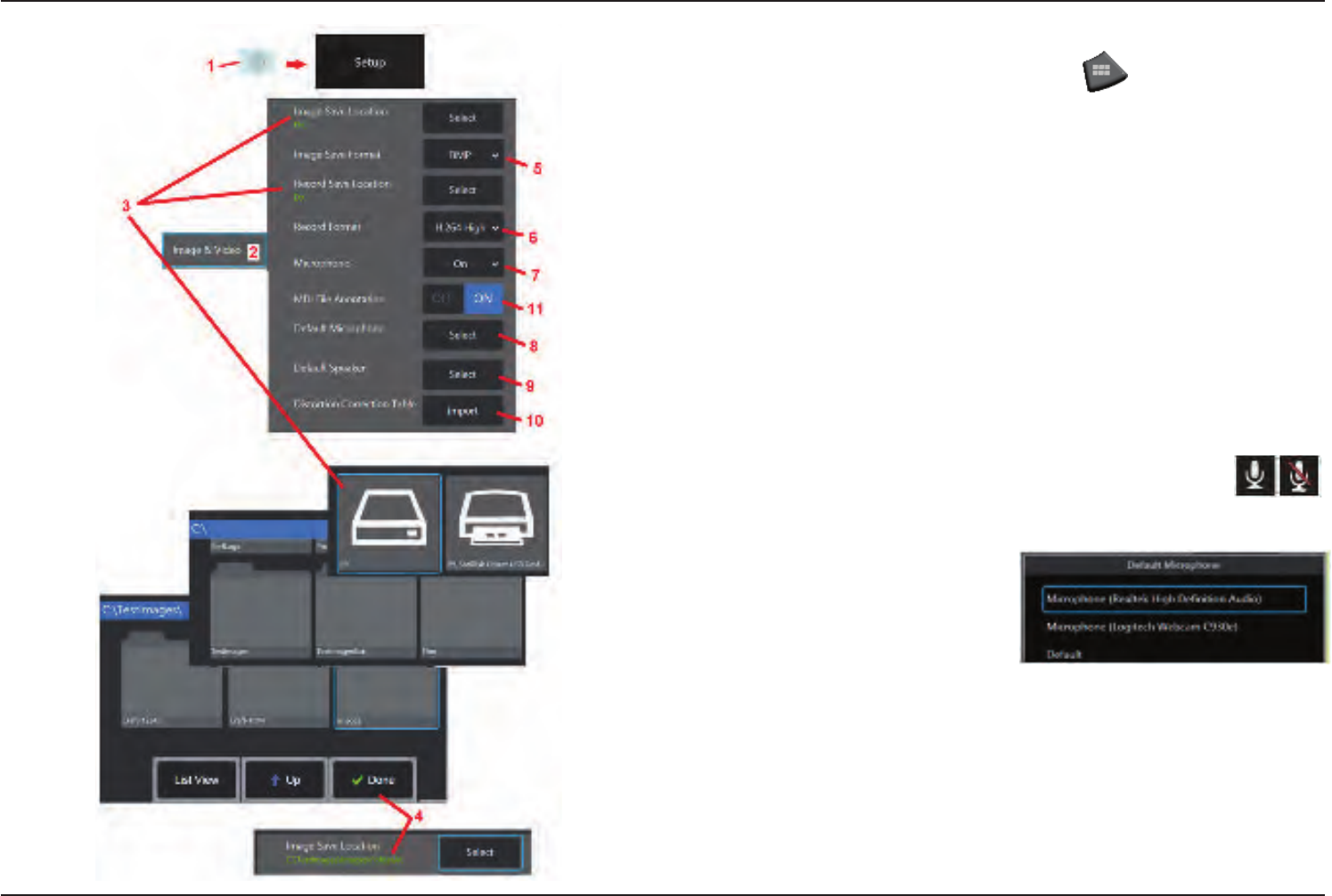
Image & Video Setup
1 – Tap the on-screen GE Logo (or press the hard key) to open the
Global Menu, then open the Setup Menu.
2 – Select to Image and Video related settings and defaults.
3 – Follow the procedure shown here to change either the Image Save Location or
Video Save Location. These represent the two locations where quick-save images
or videos are automatically stored. In the example shown here, these locations are
both initially set to the D: drive. Press the Select soft key and then choose the desired
directory path. When the desired storage location is opened, select the Done soft key
to complete the process.
4 – Using the process outlined above, the default Image Save Location is changed to
C:\TestImages\Images\FolderA\. This is the location into which quick-saved images will
be stored (Click here to learn more about Saving Images).
5 – Choose either BMP or JPEG as the default image le type.
6 – Set the video recording format to either H.264 High or H.264 Low. (Click here to
learn more about Working with Video).
7 – Determines if the microphone icon (at right) appears in the display’s
bottom right corner during video recording. When displayed, tap the
icon to mute or unmute the recording of sound along with video. Click
here to learn more about muting or turning sound ON when recording
live video.
8 – When set to Default, the system
will normally recognize the connected
Microphone. Alternatively, choose a
microphone from those available (choices
are only those devices already connected
to the Visual iQ or paired via Bluetooth).
9 – When set to Default, the system will normally recognize the connected Speaker.
Alternatively, choose a speaker from those available (choices are only those devices
that are already connected to the Visual iQ or paired via Bluetooth).
10 – Should a not-yet-dened tip conguration require an alternative Distortion
Correction Table, Contact GE Technical Support. A table supplied by GE Technical
Support will include instructions on how to Import the le.
11 – When set to OFF, the menu-directed inspection stage name is not saved in the
image but will still appear during the MDI process.
25
07/30/2014
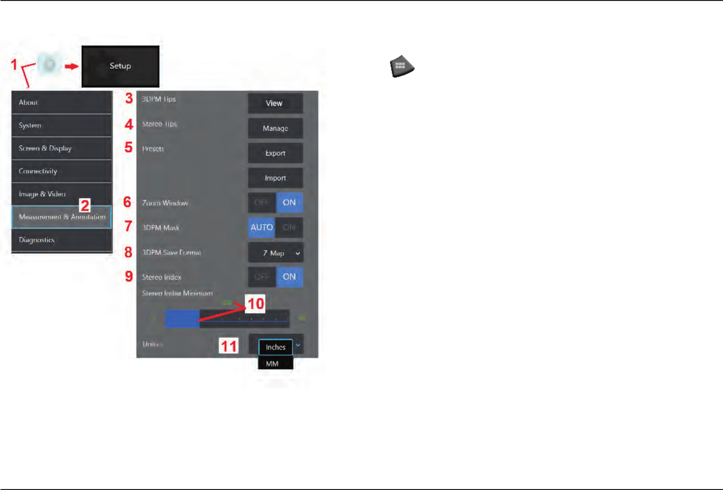
Measurement & Annotation Setup
1 – Tap the lower-left corner of the display (typically contains a GE Logo) or (or press
the hard key) at any time to open the Global Menu, which provides access to
the Setup Menu.
2 – Select to alter the Measurement and Annotation-specic settings shown here.
3 – View the list of 3DPM Tips already calibrated for use with the attached probe.
4 – Select to view a list of Stereo Tips already-calibrated for use with the attached
probe. The Add Tip and Edit List options are not intended for general use. Deleting
a tip through the Edit List option will permanently remove that tip’s calibration data
requiring the probe and tip to be returned to an authorized GE Inspection Technologies
service center for re-calibration.
5 – Save Preset Annotation (notes) to an external storage device or Import preset notes
to the instrument from an external device.
6 – Displays or removes the Zoom Window (used for detailed cursor placement during
measurement).
7 – Select AUTO to show the 3DPM red/yellow un-measurable pixel mask only when a
cursor is placed on a red/yellow pixel. Select ON to always show the pixel mask when
measuring.
8 – Select Z-Map for most usage. P-Map images contain additional data and may be
requested by GE Technical Support to aid in troubleshooting.
9 – Controls the display of the Stereo Index, which appears during Stereo Measurement.
Click here for more about Stereo Index.
10 – Sets a threshold value for the Stereo Index below which the index ashes during
Stereo Measurement. This may be used to warn the user of low-index measurements
where the accuracy may be reduced.
11 – Specify the unit of measurement as Inches or Millimeters.
26 07/30/2014
Capturing and Adjusting Images
Steering the Probe
When you are viewing a live image, you can aim the probe’s camera by controlling its
bending neck.
1 – Steering the Bending Neck: While viewing a live image, move the joystick toward
the feature you want to see. The bending neck articulates so that the probe tip moves
in that same direction.
2 – Straightening the Bending Neck: Long press this button to HOME or straighten the
bending neck for safe withdrawal and storage of the insertion tube.
3 – Setting the Steering Mode: Short press this button to choose between Steer or
Steer and Stay mode. In either mode, the bending neck articulates to follow the joystick
motion. They differ in how they behave after the joystick is released (click here to learn
how to setup the sensitivity of either mode). Steer mode allows the bending neck to
drift towards a straight position when the joystick is released. Steer and Stay mode
holds the bending neck in its articulated position when the joystick is released. If you
move the joystick while in Steer-and-Stay mode, the bending neck articulates. When
you stop moving the joystick, the bending neck stays in the new position. This icon
appears when in Steer and Stay mode.
4 – Tip Map. This on-screen icon indicates the relative positions of the steering motors.
When the illuminated dot appears in the center of the crosshairs, the motors are centered.
The bending neck position generally follows the motor positions but is affected by the
shape of the insertion tube and other mechanical effects. The further the dot appears
from the center of the icon, the more the bending neck is articulated. Depending on
the rotation of the insertion tube and camera, the viewing area may or may not align
with the direction indicated on the Tip Map.
Guiding the Insertion Tube Into the Inspection Area
With the desired optical tip installed, guide the insertion tube into the inspection area.
Use your hands to push the tube until it reaches an area you want to inspect. Twist the
insertion tube gently to bring the desired scene into view. Accessories are available to
make it easier to maneuver the tube:
• Rigidizers: Rigid or semi-exible guide tubes (available in different lengths) keep the
tube supported as you insert it or allows the tube to span a recess.
• Grippers: Cylindrical handles that slide over the insertion tube to make it easier to
control. Grippers are threaded to connect to rigidizers and to access port couplers.
27
07/30/2014
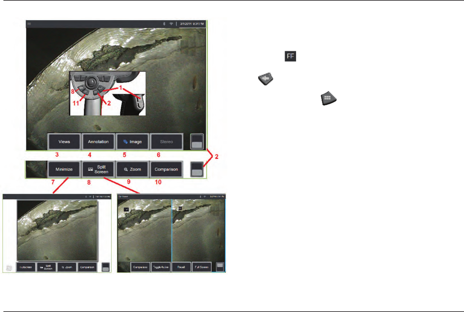
Freezing the Image
Freeze an image to temporarily capture it for review or adjustment. Moving the joystick
in a frozen view does not articulate the probe tip.
1 – Briey press either of these keys or tap anywhere on a live on-screen image to freeze
the display. The icon appears in the upper left corner of the display and the soft
key menu opens, allowing for adjustment of the frozen image. Reverse this process (or
press ) to unfreeze the display.
2 – Tap (or press and hold the key) to toggle between the upper and lower soft
key menus. Double tapping in this location hides or displays the soft keys and status bar.
3 – Select any one of up to four Views available when a 2D image is frozen or six Views
when a 3DPM image is recalled (click here to learn more about each view).
4 – Add notes or arrows to the frozen image (Click here to learn more about annotating
images).
5 – Select and adjust four image transformation settings including Brightness, Distortion
Correction, Invert, and Inverse+. (Click here to learn about image settings).
6 – When a stereo tip is calibrated to the system, Stereo appears in white text. Press
to perform stereo measurement. If no stereo tips are calibrated, Stereo appears in
gray and may not be selected. (click here to learn more about Stereo Measurements).
7 – Minimize the image to view unobscured by soft keys and status bar.
8 – Opens a Split Screen showing both frozen and live images. Press Full Screen to
return to single screen view. (Click here to learn about working with Split Screens).
9 – Zoom in or enlarge a portion of the frozen image (Click here to learn about the
Zoom feature).
Note: If you zoom in on a frozen image and then move the joystick or drag the image
with your nger, the image pans as the system electronically reviews the entire image.
10 – Measure features of the frozen image (Click here to learn about Comparison
measurements).
11 – Press or press-and-hold to Save the frozen image (Click here to learn about the
Save feature).
28 07/30/2014
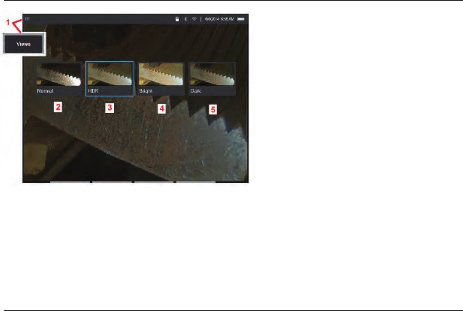
Selecting a View
When a 2D image is frozen (or a 3DPM image is recalled), the user can select
from various Views as described below.
1 – Anytime an image is frozen, select to choose from all available View options.
2 – Displays a normal dynamic range image created by applying Adaptive
Noise Reduction (ANR) processing to live video frames prior to the freeze request.
3 – HDR is a high dynamic range image generated by combining normal
brightness ANR images captured before the freeze request with images of
different brightness levels captured after the freeze request. This reduces the
glare (number of saturated pixels) and increases brightness in dark areas.
4 – Displays a view similar to HDR but gives up some detail in bright areas to
further brighten dark areas.
5 – Displays a view similar to HDR but gives up brightness in dark areas to show
more detail in bright areas.
Note: To optimize the quality of all captured images, hold the probe tip still
at the time of capture. Increasing the live image brightness prior to image
capture will improve the quality of the "HDR" and "Bright" images in darker
areas.
Note: Point Cloud and Depth Prole views are only available when working
with 3DPM images. Click here to learn more about working with these views.
Note: Once an image is saved with any one of these View options active, only
that option and Normal are available when the saved image is recalled.
29
07/30/2014
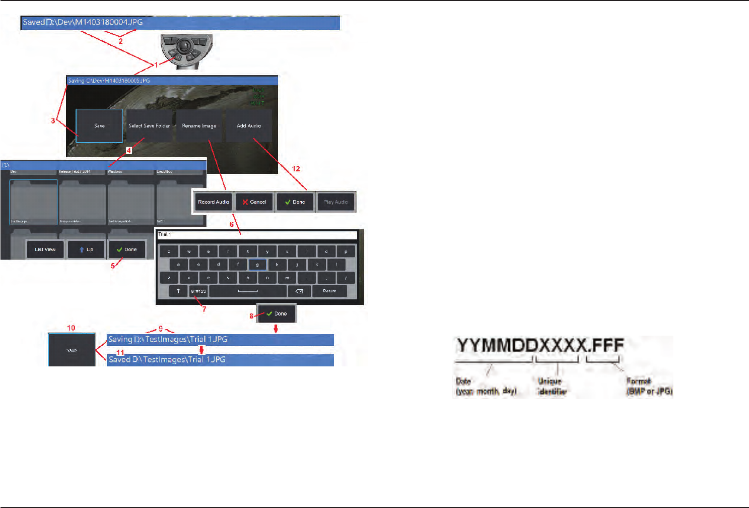
Saving Image Files
Image les can be stored in the Visual iQ or a detachable device. The Quick-Save
feature stores a le with a default name and le type in a default directory (Click here
tolearnmoreaboutsettingdefaultlenames,types,anddirectories). Alternatively,
use the Save Options Menu.
1 – Short press of this hard key to Quick Save the displayed image in the default directory.
A long press of this key opens the Save Options Menu.
2 – At all times, the intended saving location (in this case the Dev directory located on
the D drive) is listed here. After a le is stored, the status bar at the top of the screen
indicates “Saved.” The le name (described below) and format are also listed.
3 – While in the process of assigning an alternative name or destination for the image
le, the status bar at the top of the screen indicates “Saving.”
4 – Choose an alternative directory into which the le will be stored.
Note: Tap and open the target folder
5 – Tap to complete the target directory selection.
6 – Select to Rename the le prior to saving. The virtual keyboard opens.
7 – Select to choose from numeric characters or symbols.
8 – Tap after typing the desired name.
9 – The status bar now indicates the new target directory (in this case, TestImages) and
the new le name (Trial 1).
10 – Tap to complete the saving process.
11 – The status bar now indicates that the le has been “Saved.”
12 – Add audio comments to the le before completing the saving process (Click here
to learn more about recording audio).
30 07/30/2014
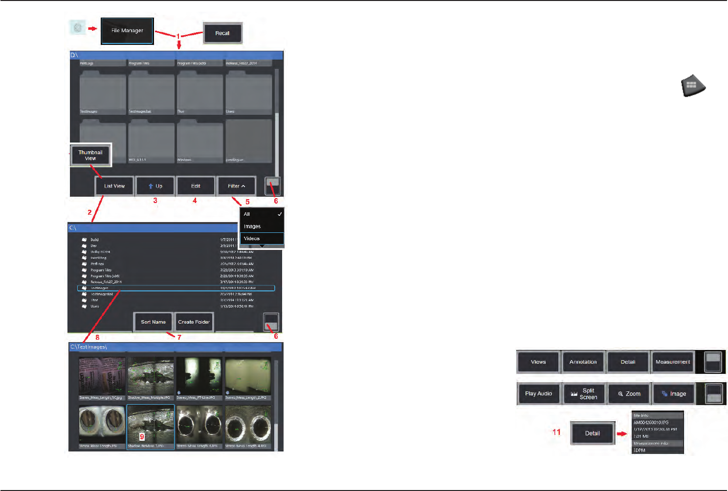
Working with a Recalled Image
Image and video les can be stored in the Visual iQ or a detachable device. The Recall feature
allows these stored les to be displayed, measured, and annotated. Follow these steps to
locate and Recall a stored le:
1 – Recall a stored image or video by tapping the on-screen GE Logo (or press the hard
key) to open the Global Menu, then select File Manager.
Note: Selecting the Recall soft key (when enabled) automatically opens the last saved image
(provided one has been saved since the iQ was last powered ON). Moving the joystick (or
dragging the display with your nger) left or right recalls other images stored in the same
folder as the originally recalled image.
2 – Controls the File Manager’s appearance (both Thumbnail and List Views are shown here).
3 – Select to navigate to the next higher directory within the File Manager.
4 – Select to Copy, Rename, and otherwise Edit stored les (Click here to learn more about
theleEditfeature).
5 – Choose which le types to display.
6 – Tap to switch between the Soft Key Bar’s top and bottom row. Double tapping in this
location hides or displays the soft keys and status bar.
7 – Determine the order in which folders or les are listed (by date or alphabetical order).
8 – Tap screen to select the folder to open.
9 – Tap screen to select the le to Recall.
10 – Once an image is recalled, various actions can be taken (see soft key menus below). Click
on any of the following to learn more about the function:
-Select the displayed View
- Annotate by adding text or arrows
-Measure image features
-Play recorded audio
- Open a Split Screen to display
any two images (live, frozen, or
recalled)
- Use Zoom to magnify
- Adjust the Image
11 – Press to open an onscreen
list of the displayed file’s Detailed
properties.
31
07/30/2014
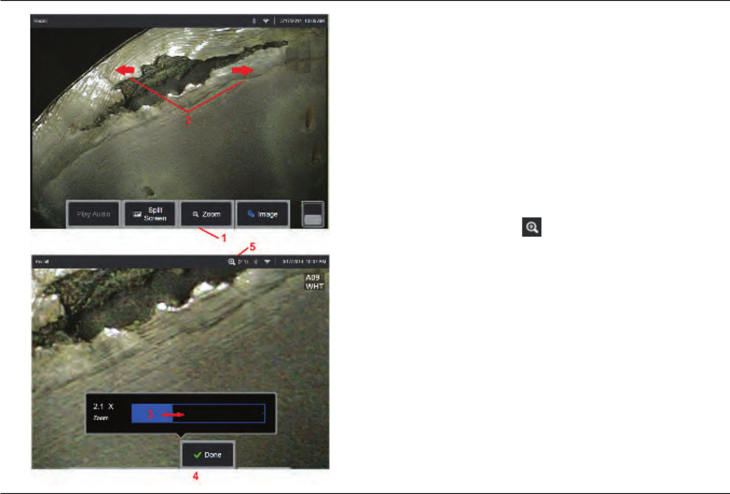
Zoom to Magnify
The Zoom feature magnies the view of live, frozen, and recalled images. Because the
zooming process is digital, pixilation increases as the image is magnied.
Note: The Visual iQ oers two equivalent zooming methods.
1 – Select this soft key to launch the Zoom control bar.
2 – Position one nger on either side of a feature, then slide ngers apart to increase
magnication (Zooms IN). Moving ngers towards each other decreases magnication
(Zooms OUT).
3 – Touch and slide this bar left or right (or move it with the Joystick) to decrease
or increase the amount of image magnication. Repeat this process to return to a
unmagnied image (Zoom value of 1X).
4 – Select when the image magnication process is complete.
5 – When the image is zoomed, the icon appears in the display’s status bar along
with a value representing the amount of image magnication (2.1 times is shown here).
Note: Whenever a frozen or recalled image is magnied with the Zoom feature, simply
drag your nger across the display screen or use the Joystick to view o-screen
portions of the magnied image.
32 07/30/2014
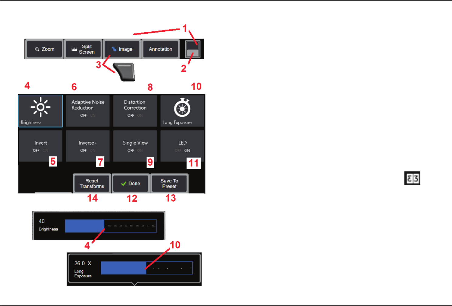
Image Transformation Settings
These settings, accessed by selecting the Image Menu, alter the appearance of live
images. (Some of these settings also affect frozen or recalled images.) At any time, the
values assigned to these eight transformation settings can be saved as a user-named
Preset. When recalled, all transformation settings will revert to these “preset” values.
(Click here to learn about working with Preset Image Transformation Settings)
1 – Double tap this switch to hide or display the Soft Key Bar.
2 – Tap to switch between the Soft Key Bar’s top and bottom row.
3 – Tap on-screen Image button or press the corresponding key to display the Image
Menu.
4 – Tap the on-screen Brightness icon to adjust the displayed image. The adjustment
bar shown will then appear – drag it to the left or right. You can adjust the brightness of
live, frozen, and recalled images as well as recorded video. The brightness level selected
when an image is saved will be maintained when the image is recalled.
Note: When viewing live images, adjusting the brightness means controlling exposure
time and camera gain. When viewing still images or recorded video, adjusting the
brightness means controlling digital gain.
5 – Tap on-screen Invert icon to turn ON or OFF. When turned ON, appears at
the top of the display. This feature horizontally ips any image.
Note: This feature allows you to “correct” images when using a side-view optical tip,
since the prism contained in these tips would otherwise show an inverted image.
33
07/30/2014
6 – Tap to turn Adaptive Noise Reduction (ANR) ON or OFF. ANR works to reduce the
amount of noise (which appears as a grainy image) visible when the probe is positioned
in a dark area. The ANR setting (ON or OFF) applies only to live video. ANR is automatically
applied to reduce noise in all frozen and saved images, even when the ANR setting is set
to OFF. When turned ON, appears at the top of the display.
Note: Keep the probe still when capturing an image. Noise increases with probe movement.
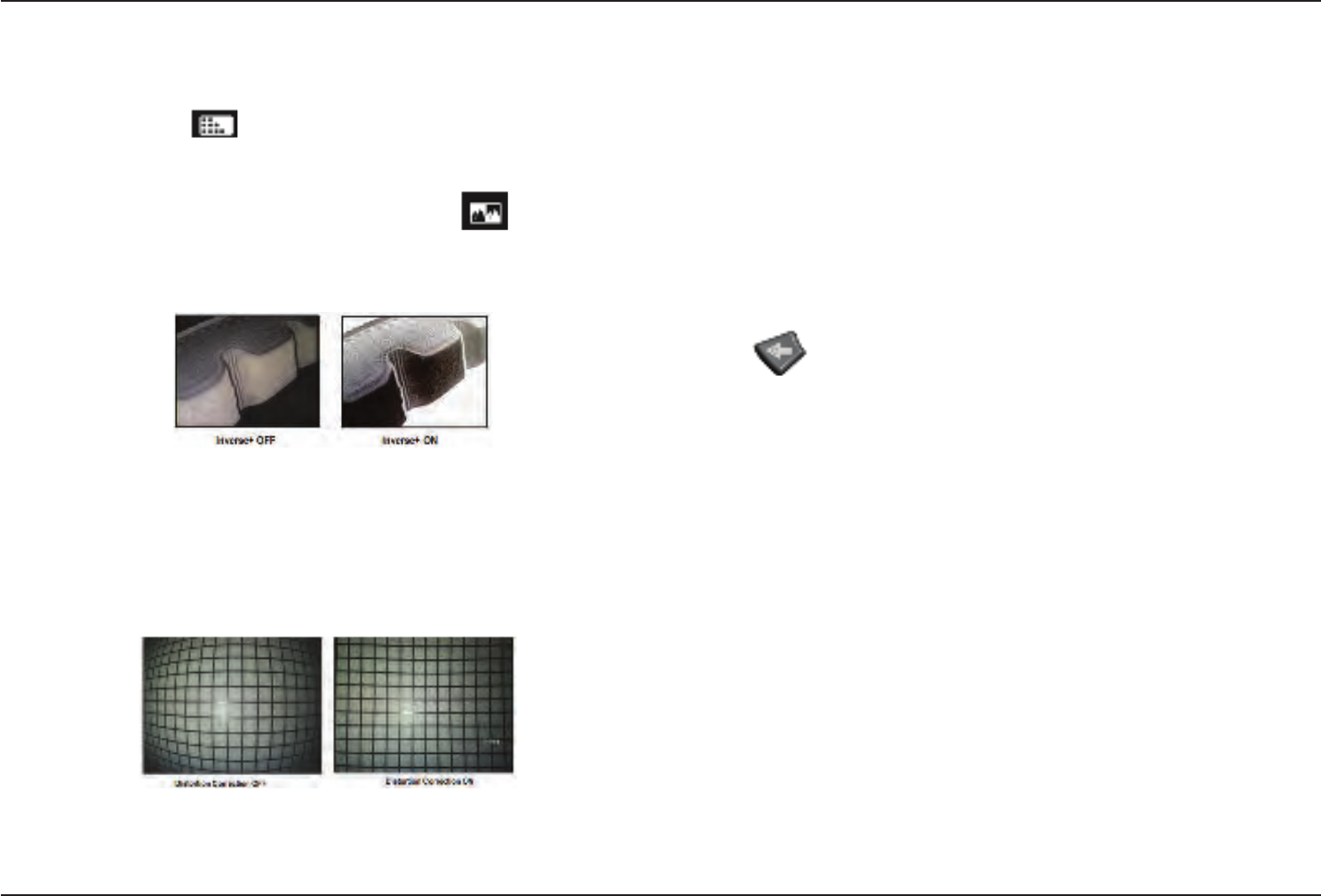
7 – Tap to turn Inverse+ either ON or OFF. When turned ON, appears at the top
of the display. The Inverse+ function enhances image contrast – often making subtle
details more visible in low light or poor contrast images. Turning Inverse+ ON reverses
the image’s dark and light areas, much the same as a photographic negative.
8 – Tap to turn Distortion Correction either ON or OFF. The Distortion Correction function
corrects the wide-angle edge distortion that occurs when using optical tips with various
angle elds of view
Note: When saving a corrected image, the face of the image will be labeled 120 Deg.
Note: When viewing a corrected image, the selected tip eld of view (FOV) angle is overlaid
in the lower right corner.
9 – Tap to turn the Single View feature ON or OFF. Single View is useful while positioning
a stereo optical tip. This feature makes it easier to navigate the camera by temporarily
eliminating the second image.
10 – Tap the on-screen Long Exposure icon to brighten live images by increasing
the camera’s maximum exposure time. Exposure settings can vary from 1X to 600X.
Note: The longer the exposure, the greater the risk of blurring the image. Keep the probe
tip as still as possible when capturing an image with a long exposure.
11 – Tap to turn the illumination LED ON or OFF
12 – Tap on-screen DONE button or press the corresponding key to close the Image
Menu and return to the Soft Key Bar. Any changes to image transformation settings
will remain until manually modied or otherwise altered by recalling a stored Preset.
Pressing while viewing live video turns off all transforms.
Note: Any changes made to image transformation settings are lost during power down.
13 – Tap on-screen Preset button or press the corresponding key to create and
name a Preset containing the values currently assigned to each of the eight Image
Transformation settings. Recalling the Preset later allows you to automatically change all
Image Transformation settings to the stored values. (Click here to learn about Working
with Preset Image Transformation Settings).
14 – Tap on-screen Reset Transforms to restore the factory default values for each
of these eight settings.
34 07/30/2014
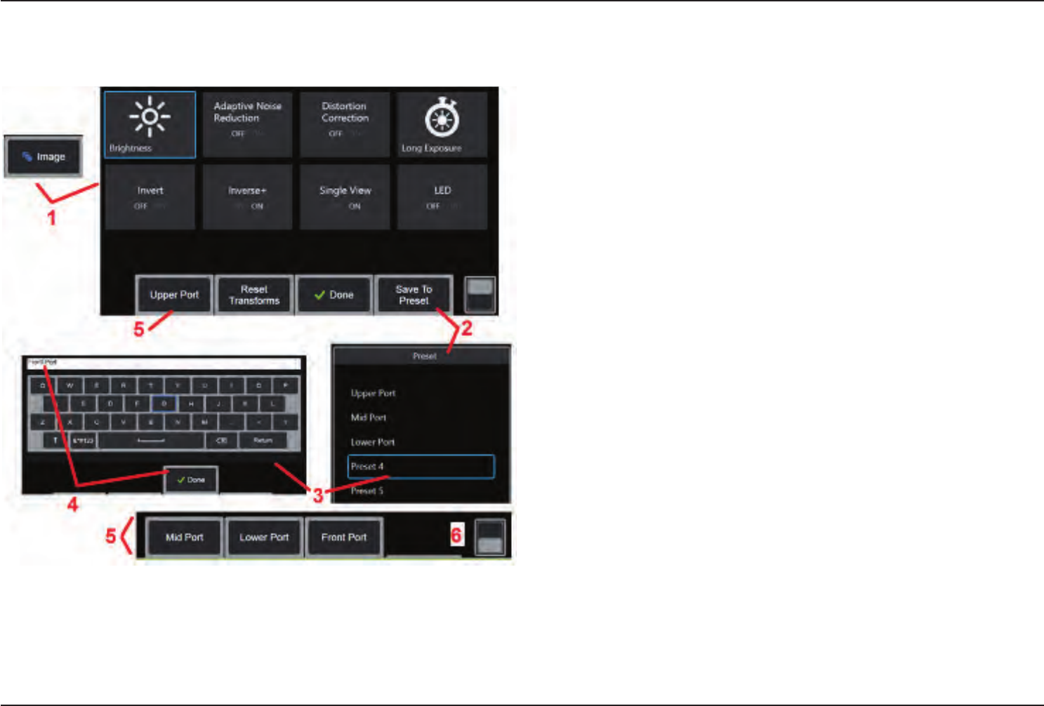
Working with Preset Image Transformation
Settings
Values assigned to the image transformation settings can be saved as a user-named
Preset. When recalled, all transformation settings will revert to the values assigned when
the Preset was created. Each user-named Preset appears as a soft key in the Image
Menu. To load a Preset, simply select its soft key or press the corresponding button.
1 – Tap the on-screen Image button or press the corresponding key to display
the Image Menu, which contains the eight image transformation settings.
Adjust settings as needed.
2 – To save the image transformation settings in a user-named Preset, select Save to
Preset. The Preset List will open.
3 – Tap to select any one of the ve Presets. The virtual keyboard will open, allowing
you to name the Preset.
4 – After entering a name for the Preset, select Done.
5 – The user-named Presets appear as soft keys in the Image Menu. Select any of these
to load the settings stored in the corresponding Preset.
6 – Tap here to toggle between the upper and lower Soft Key Bars.
Note: Presets are stored only for the prole that is logged in at the time they are created.
35
07/30/2014
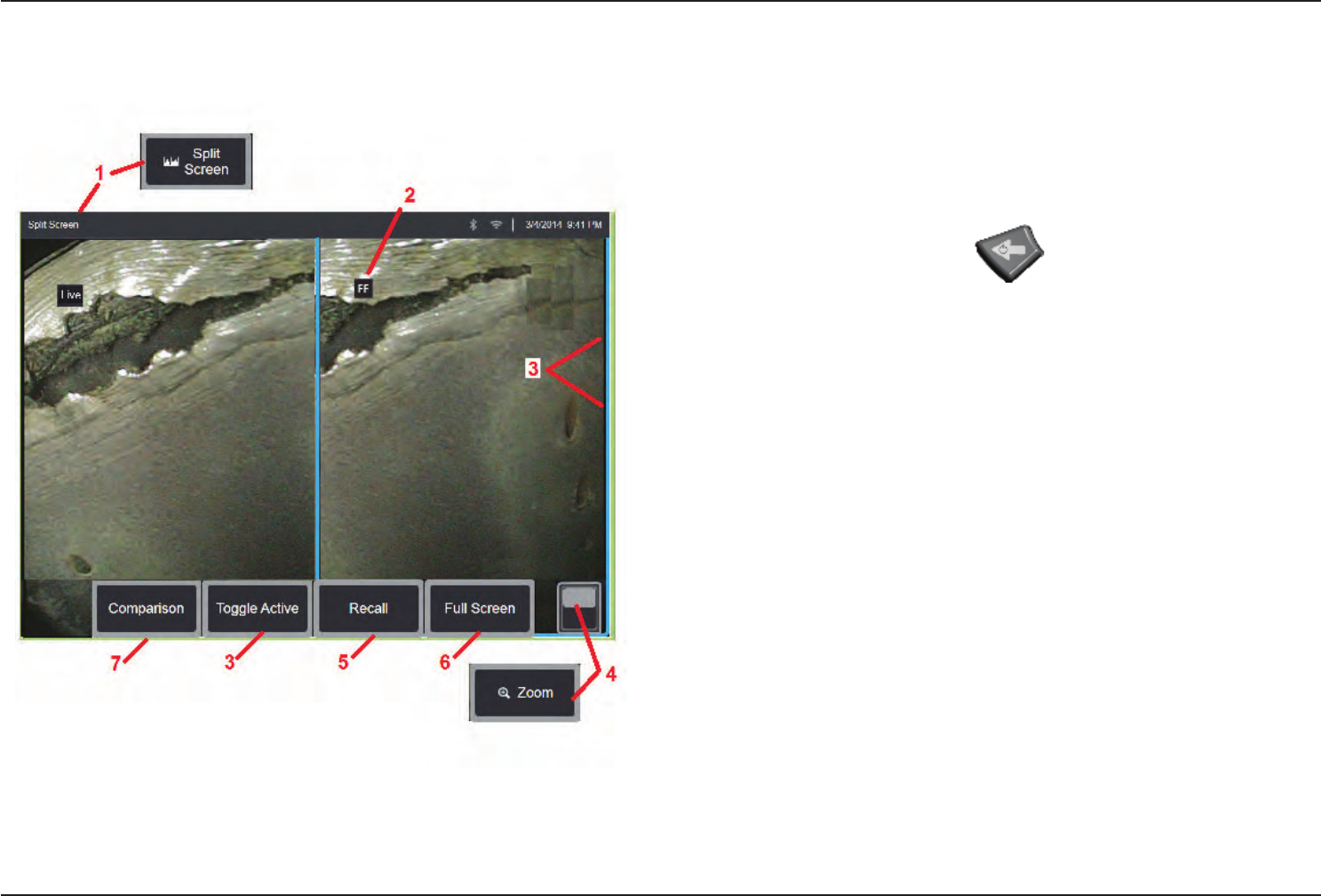
Working with a Split Screen
A split screen displays two images side-by-side in any combination of live, frozen, or
recalled. Since half-screen still images are cropped, dragging a nger across the display
or moving the joystick allows you to pan side-to-side within the image.
1 – Press at any time to launch the Split Screen feature. One half of the screen will initially
show a live image, the other shows a frozen version of the image that appeared when
Split Screen was selected.
Note: To exit Split Screen mode, press until a full-screen reappears.
2 – Each displayed image will be identied as either Live, Frozen (FF), or Recalled.
3 – Select which image is active by touching either side of the split screen, or by selecting
this soft key, or moving the joystick left or right. Only one image is active at a time, as
indicated by the blue outline around the active image.
4 – Change the magnication of the active image by zooming IN or OUT (Click here to
learn more about the Zoom feature).
5 – Select to Recall a stored image into whichever side of the display is currently active
(Click here to work with Recalled images).
6 – Temporarily displays the active image as a full screen. This action DOES NOT cause
the display to exit Split Screen mode.
7 – Measurement mode available for still images. This soft key is labeled with the most
advanced measurement mode (3DPM, Stereo, or Comparison) available for the active
still image. It allows measurement to be entered with the active image. Exiting from
measurement will return to the current Split Screen view. (Click here to learn more
about Comparison measurement mode).
36 07/30/2014
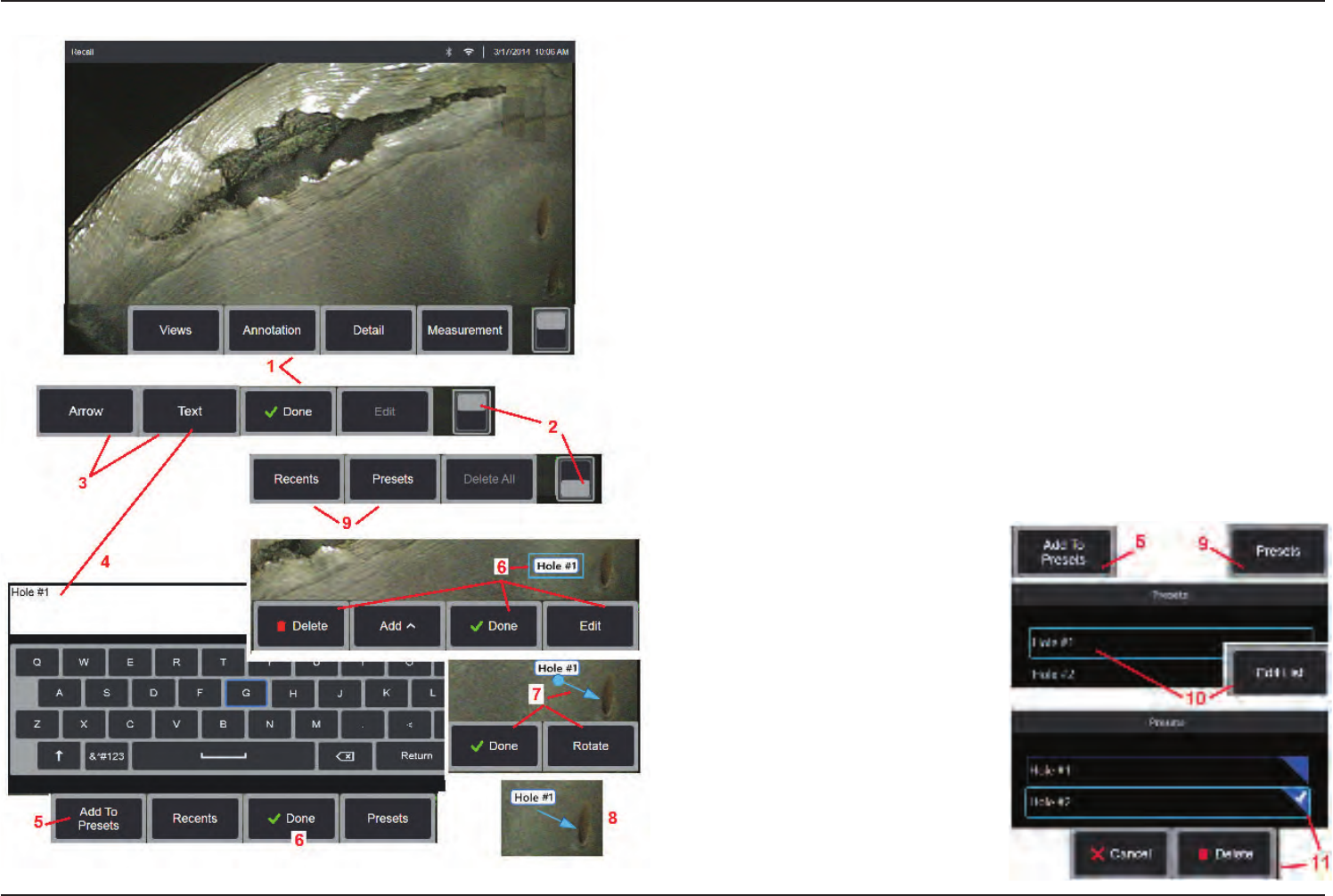
Annotating with Text and Arrows
Annotating an image means adding text or arrows to point out areas of interest: cracks,
indications, etc. You can annotate live, frozen, and recalled images.
1 – Select to launch the Annotation feature.
2 – Tap to switch between the Soft Key Bar’s top and bottom row. Double tapping in
this location hides or displays the soft keys and status bar.
3 – Adding annotation begins by selecting Text or Arrow.
4 – Selecting Text opens the Virtual Keyboard. Enter the desired note.
5 – Select to add the entered note to a list of up to 100 Preset notes, which can be
repeatedly used without typing.
6 – Select Done when nished typing the note, which will appear on the image
surrounded by a blue box indicating it is selected. While in this selected state, the note
can be moved (by dragging with your nger or using the joystick), Edited, or Deleted.
Select Done again to de-select the note.
7 – A selected Arrow (added in the same way as a note) appears with a ball at one end.
Move the arrow around the display by dragging with your nger (near the arrowhead)
or using the joystick. The arrow may also
be rotated by moving the ball with your
nger or with the Rotate soft key.
8 – Select Done to de-select the arrow.
Note: Any note or arrow can be selected
by simply tapping its position on the
display.
9 – Opens the list of user-created Preset
notes (annotation). Recents shows all
recently typed notes, including presets.
10 – Once open, select and Add a Preset
note or select it for Editing.
11 – Tap in this corner (white check
appears) to identify a note for deletion.
37
07/30/2014
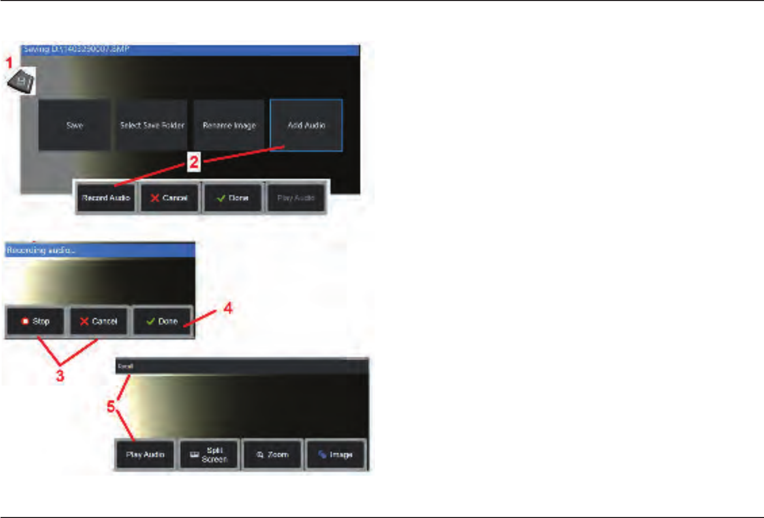
Adding Audio Notes to an Image
During the process of saving an image, audio notes can be added provided a microphone
is rst attached to the Visual iQ.
1 – Long press the Save hard key to begin the image saving process.
2 – Select Add Audio to begin the audio recording process. Be sure to have rst connected
a microphone (click here to specify the microphone attached and other Image and
Video settings).
3 – Select either control to momentarily Stop or permanently Cancel the audio recording
process.
4 – Select to complete the audio recording process. The audio notes are now part of the
stored image le. You can now play or re-record the audio notes.
5 – After recalling a stored image, the recorded audio notes can be played at any time
(Note: when an image is recalled, the Play Audio soft key may be located in the lower
soft key row).
38 07/30/2014
Working with Video
Any time during your inspection you can record video “in the background” while doing
other tasks, such as comparing images on a split screen, taking measurements, or
managing les and folders. When you record video, the system saves everything that
appears on the display, as well as background sounds and comments made near the
microphone (unless you turn off the audio). You can record video onto the internal drive
or any other removable storage device.
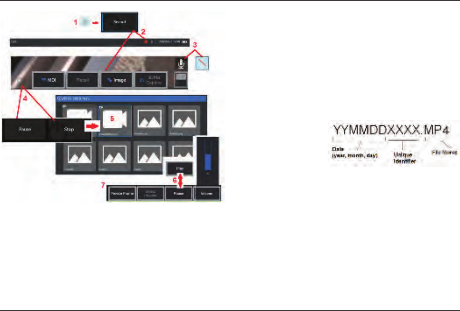
Recording Live Video
1 – Tap the lower-left corner of the display (typically contains a GE Logo) at any time to
open the Global Menu, which provides access to the video Record button.
2 – Select to begin recording video in the user-selected format (click here to learn about
conguringVideoSettings). A red circle ashes at the top of the screen throughout the
video recording process. Note that the soft keys shown here (and all other on-screen
features) will appear in the video recording. Double-tap the soft key bar's toggle switch to
move these buttons off the screen if you do not wish to include them in the recorded video.
3 – Tap to mute or turn on sound recording. Sound recording will only occur (and this icon
will only appear) if a microphone is attached to the Visual iQ and the system is properly
congured. ClickheretolearnmoreaboutconguringVideoSettings.
4 – Tap the lower-left corner of
the display and select either the
video Pause or Stop buttons.
Selecting Pause allows you
to restart the same recording.
Selecting Stop automatically
saves the video le with a default
name (see description) in the
user-dened default folder. Click here to learn Video Settings, including selecting the
defaultle-savinglocation.
Working with a Recalled Video
5– To recall a saved video le, navigate to the saved le via the File Manager (click here
torecallandrenamesavedles). Select the video (which will have an mp4 le extension).
The video will automatically replay.
6 – These soft keys control the video while it is playing. Use the joystick to rewind or
fast-forward the video.
Capturing a Still Image from Video
7 – Click here to freeze the video action at any time. Once frozen, the screen image can
be saved. Click here to learn about Saving Images.

39
07/30/2014
Measuring Features and Indications
About Measuring
The Visual iQ allows you to measure features or indications either before or after saving an image. You can save up to ve measurements per image. In order to perform 3D Phase
Measurements (3DPM) or stereo measurements, the image must be captured using a 3DPM, or stereo tip. All saved measurement images can be re-measured on a PC using soft-
ware from GE’s Inspection Technologies. For details, visit the GE-MCS website at http://www.ge-mcs.com/en/remote-visual-inspection/software.html
You can save measurement images as JPEGs or bitmaps. You can view these les, including the measurement results, in most .BMP or .JPG viewing applications, such as Windows
Paint (click here to learn about image-saving settings).
Notes:
-Measurement results are valid only when taken in air. To measure through liquid, contact GE Inspection Technologies.
-GE Inspection Technologies cannot guarantee the accuracy of measurements calculated by the Visual iQ system. Accuracy varies with the operator’s ability.
-The Visual iQ system can display measurement images that were captured on the Everest XLG3™ and XLGo VideoProbe systems, including their previously captured measurements.
However, you cannot re-measure these images on the Visual iQ.
40 07/30/2014
Measurement Types
The Visual iQ system supports three types of measurement: 3D Phase, stereo,
and comparison.
Type Advantages Disadvantages
3D Phase Over stereo or comparison measurements:
• Optical tip used to view and measure.
• Automatic tip to target range-nding
indicator.
• Full screen view.
• More accurate depth measurements.
• Cross-section prole view and measure
• Increased measurement distances are
possible
• The surface need not be perpendicular
to the tip.
• 3D point cloud view
• The system cannot measure moving
parts.
• Must measure highly reective
surfaces at an angle.
Stereo Over comparison measurements:
• More accurate.
• No known reference is needed.
• Can measure depth.
• The surface does not need to be
perpendicular to the probe view.
The system may be unable to position the
matching cursors accurately with any of
these conditions in the measurement area:
insufcient detail, repeating patterns, glare,
or smooth, straight lines to measure along.
In some cases, you can eliminate the
problem by repositioning the probe tip
and adjusting the brightness.
Comparison Over stereo measurements:
• Use the probe headguard or any other
tip optic.
• Measure with probe tip farther away.
• Measure large objects.
• Check approximate size of many items
quickly.
• Less accurate than stereo
measurements.
• Known references may not be present
and may be difcult to deliver to the
measurement site.
• Measurement surface must be nearly
perpendicular to the probe view for an
accurate measurement.
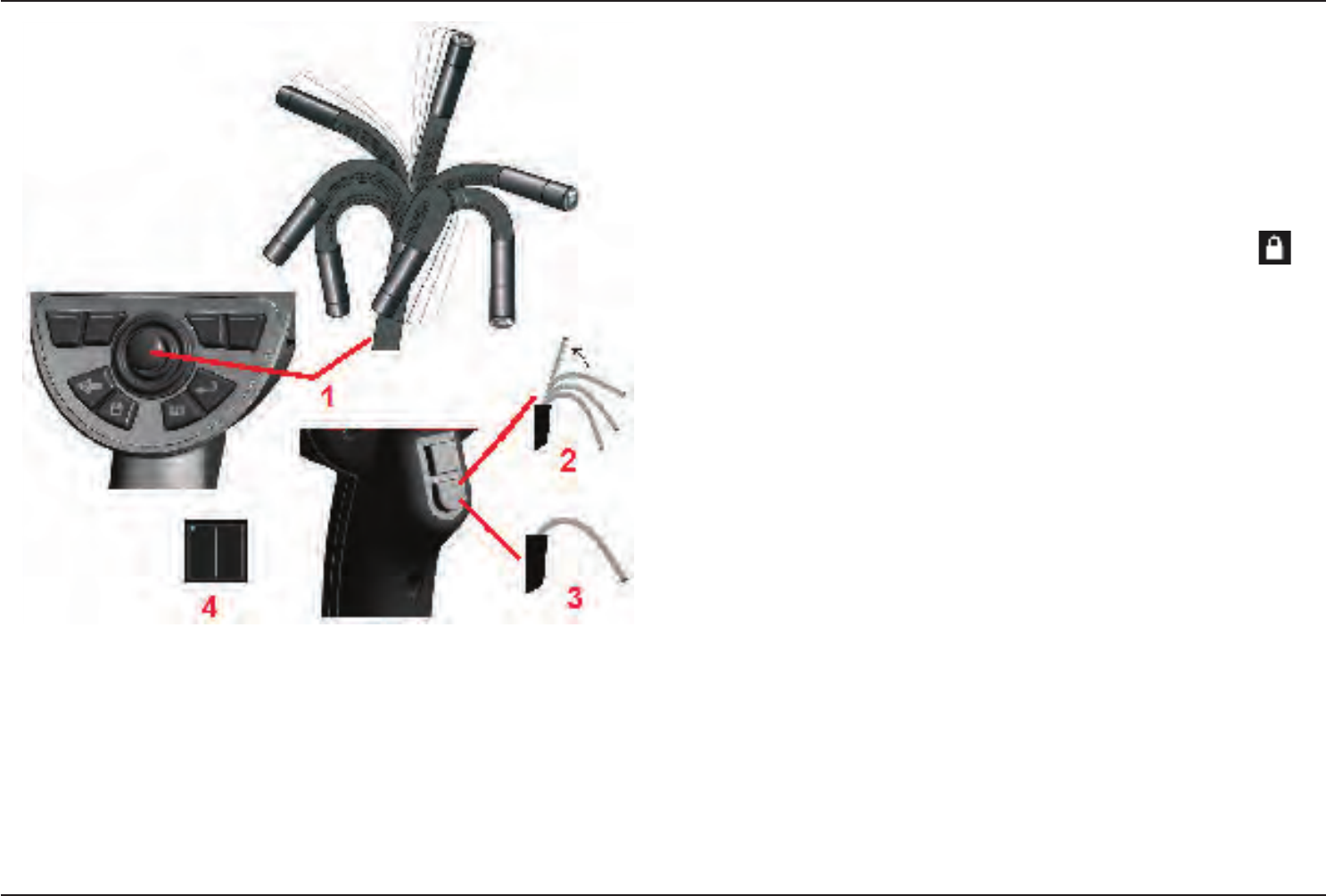
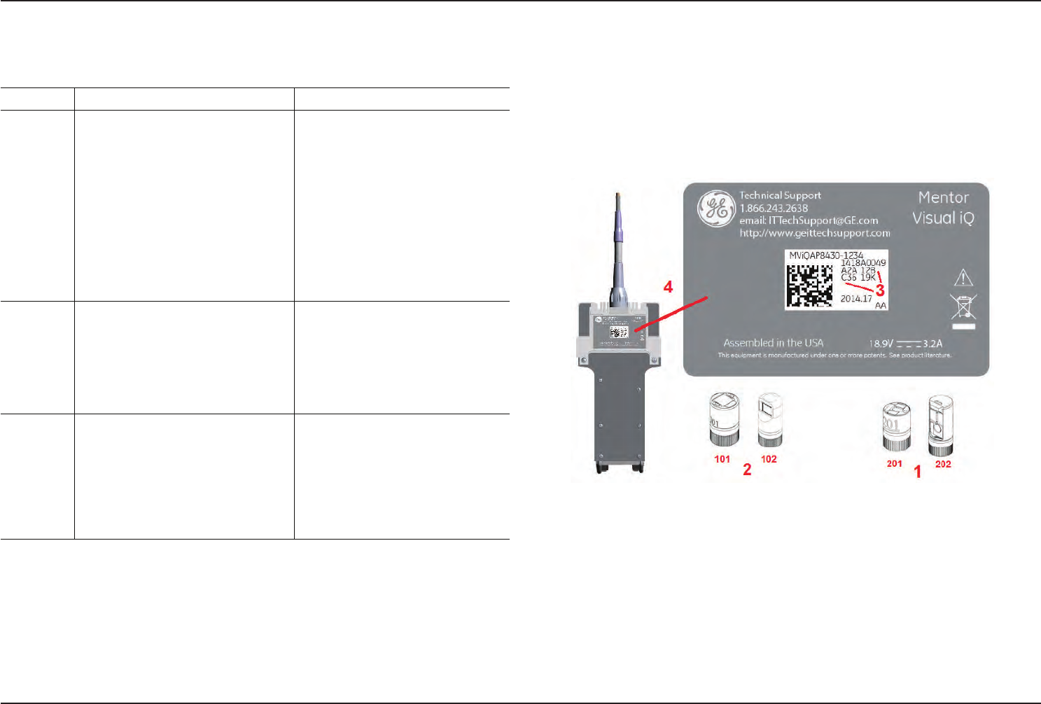
Measurement Tips
Note: 3DPM tips are automatically identied by the system. Stereo tips must be
manually selected each time a stereo measurement is performed.
Unlike standard optical tips, 3D PhaseProbe® (1) and StereoProbe® (2) measurement
tips are factory-calibrated for use with specic probes and will not measure
accurately with other probes. These tips are matched to probes by the serial
numbers (3) identied on each optical tip and each probe label (4). Calibration data is
stored in memory in the probe.
Notes:
-To ensure measurement accuracy, verify the tip’s accuracy each time it is installed.
Refer to Appendix E for verication procedures.
-The installed tip must be identied before making Stereo measurements. Click here to
view stereo tip management OR Click here to work with 3DPM tips.
To ensure that no mechanical damage has degraded their accuracy, verify
measurement tips each time you use them. See Verifying Measurement Tips in
Appendix E. To learn which tips are available for each measurement technique, see
the Optical Tip Table in Appendix B.
41
07/30/2014
3D Phase Measurements (3DPM)
3D Phase Measurement optical tips and probe capture a three-dimensional surface scan of the object. Measurements are
then made directly on the surface and displayed on the image. Preliminary steps of matching cursors or marking shadow
lines are not necessary.
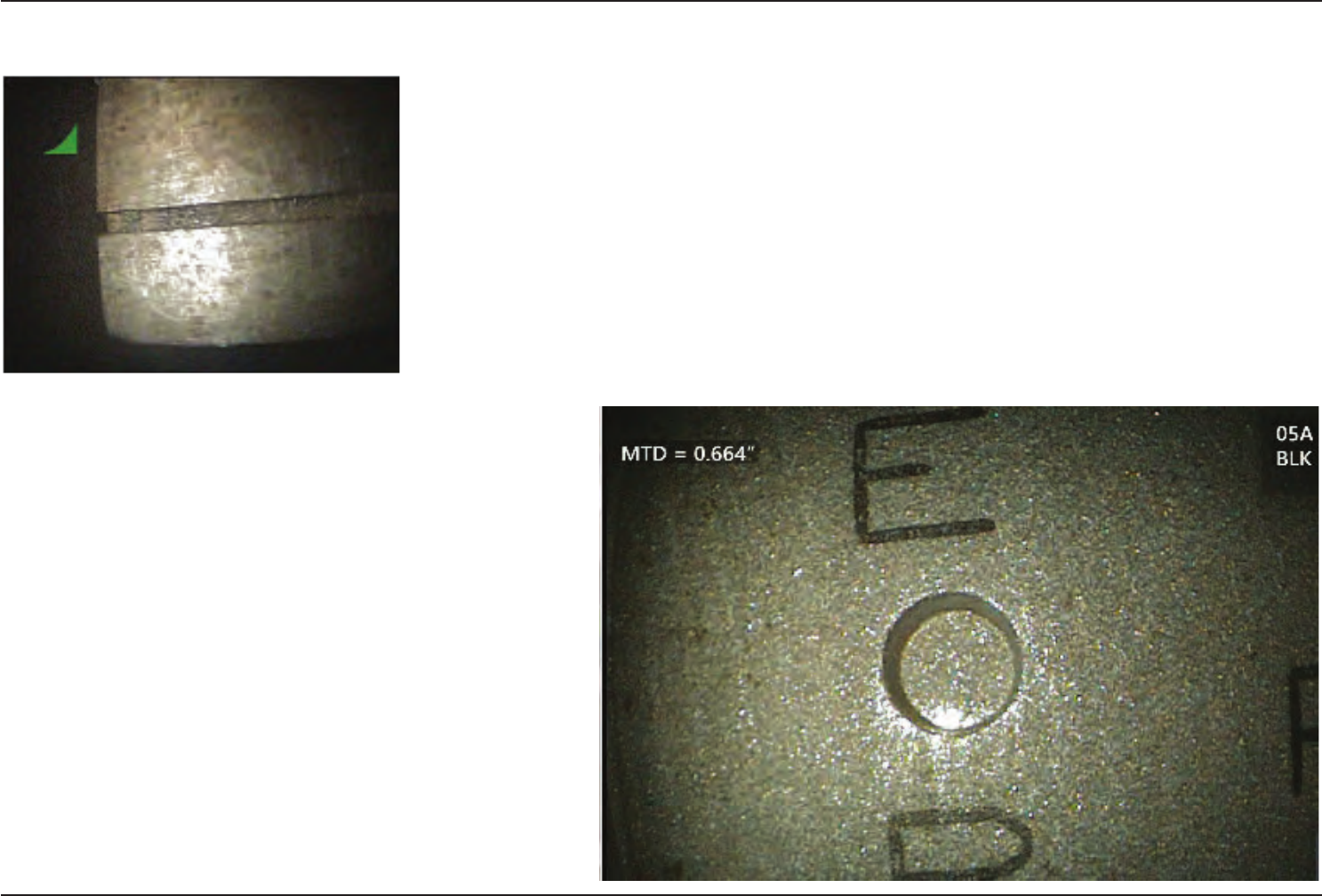
Maximum Target Distance - MTD Number
The 3D Phase Measurement system will display a number on-screen after a measurement is complete. While taking the
measurement, an MTD number will appear (see the upper left corner of the gure to the right). MTD stands for Maximum
Target Distance and is the distance from the 3D Phase Measurement tip to the surface at the point of the active cursor.
Unlike stereo measurements, 3D Phase Measurements do not use Accuracy Index.
Taking 3D Phase Measurements
As with other measurement types, Phase Measurement accuracy improves as tip-to-target distance is reduced. The range
nder bar icon can be used to gauge the suitability of the current tip-to-target distance for a given measurement. When the
surface is too far for measurement, a single bar is shown, and measurement should not be attempted. As the tip is moved
closer to the surface,
more bars are illuminated. Large length measurements may be performed with
few bars illuminated, while still achieving good accuracy. In general, the best
accuracy is achieved by getting as close to the surface as possible.
Accuracy is generally best when viewing a surface from approximately a 45°
angle, especially on surfaces that are shiny or have a speckled appearance.
When measuring surfaces with steps or long, deep features, a side view tip will
give better results if the feature or step is horizontal (as shown at right). A front
view tip will give better results if the feature or step is vertical. This is due to the
LED orientations in the tips.
To Capture a 3D Phase Measurement Image:
Step 1 – Attach either a forward view or side view 3D Phase Measurement
optical tip to the probe. Each measurement tip must be factory calibrated to
a particular probe, and may be calibrated to more than one probe. To ensure
measurement accuracy, verify the tip’s accuracy each time it is installed. Refer
to Appendix E for verication procedures.
Step 2 – Verify that the Visual iQ system has automatically identied the 3DPM
optical tip. The range nder appears near the upper right corner of the live image.
Step 3 – Initiate the Image Capture sequence as described in the following
section.
42 07/30/2014
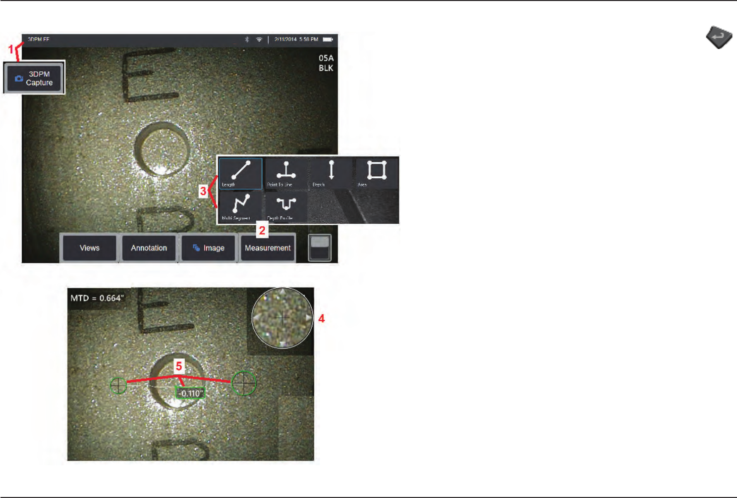
Capturing 3DPM Images
1 – When the target is in position, select this soft key (or long hold ).
The 3D Phase Measurement scan will begin.
Note: Hold the probe still for approximately one second during the surface
scan. Multiple images are taken to complete the scan, and the probe must
be held still during this sequence. Do not move the probe until the Capturing
images... keep probe still caution disappears.
2 – Select to begin the measurement process.
3 – Choose the type of phase measurement.
4 – The Patented Zoom Window automatically opens allowing for precise
positioning of the active cursor. Tap the window’s edges (or tap on the cursor,
then control with the joystick)to adjust the active cursor position. Click here
tolearnaboutturningtheZoomWindowonoro.
5 – Place cursors on the desired feature. Up to ve measurements may be
placed on each image.
Note: The system will wait up to 1.5 seconds for movement to stop
before starting a 3DPM capture. If movement does not stop, a message
displays and the capture is not attempted. If movement begins during the
capture, the system pauses the capturing process, waits for movement
to stop, and attempts a second capture. If either attempt allows enough
frames to be captured without movement to provide sucient surface
coverage, measurement is allowed. If neither attempt is completed without
movement, a message indicating that the capture was aected by motion
is displayed. This may result in more un-measurable (red) pixels or a slightly
higher noise level than would be achieved with no movement. The system
does not allow measurement if the movement was sucient to substantially
degrade 3D data quality.
43
07/30/2014
Making3DPMMeasurements(DepthProleExample)
Note: While the following procedure applies specically to a Depth Prole
measurement, refer to this procedure and the information in the section titled
Types of Phase Measurement to conduct any type of 3DPM.
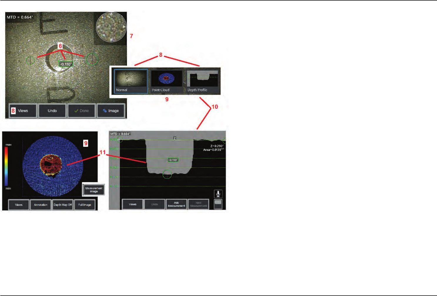
6 – To create a DepthProle measurement, place the rst and second cursors
on a at surface on opposite sides of the area of interest. This procedure is
described in a following section.
7 – Patented Zoom Window allows for precision positioning of the active cursor.
Tap the window’s edges (or tap on the cursor, then control with the joystick) to
adjust the active cursor position. Click here to learn about turning the Zoom
windowonoro.
8 – Use to select from available Views. Click here to learn about the Normal
view and three additional views not listed here.
Note: Depth Prole view (described in a following section) is only available if
the 3DPM image includes a Depth Prole measurement.
Note: Measurements can be performed with any of the Image Views selected.
9 – Point Cloud view, described below, evaluates level of noise relative to
indication size while verifying proper cursor and prole position for the desired
measurement. Choose between Measurement and Full Image to view only the
area around the active measurement or the entire image. When a Point Cloud
is displayed, turning on the Depth Map uses color to approximate the depth of
an indication (see left-hand scale).
10 – The DepthProle view is available only after a DepthProle measurement
has been made.
11 – The DepthProle view provides a cross-section with the line connecting
the two reference cursors serving as a sectioning line.
44 07/30/2014
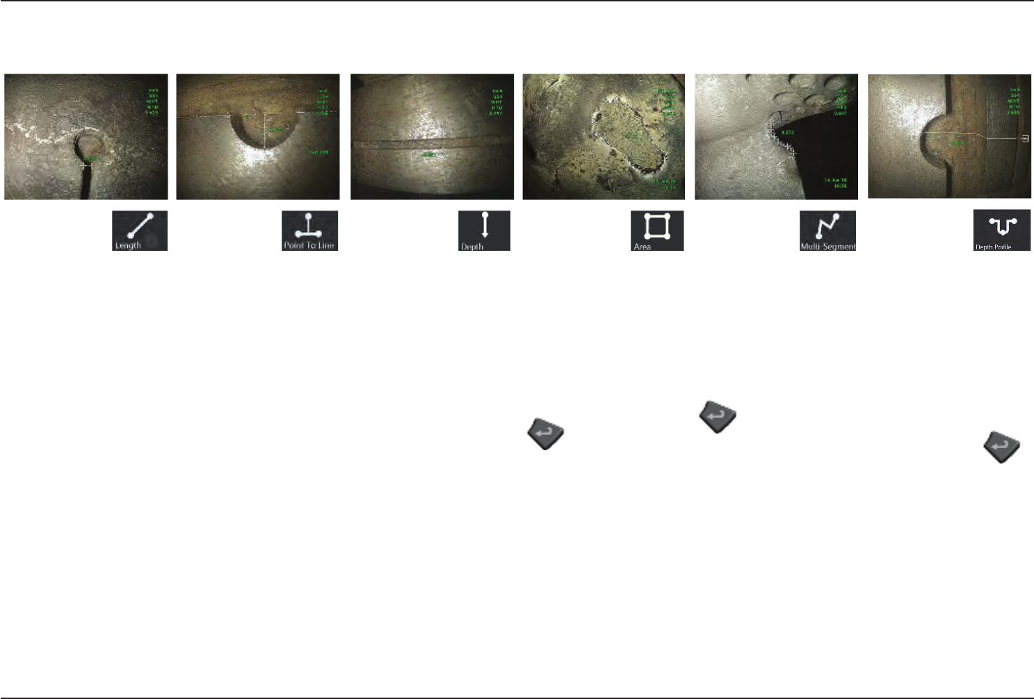
Types of 3D Phase Measurements
This section specically addresses cursor placement for each type of 3D Phase Measurement.
Description:
Linear (Point-
to-Point)
measurement
Cursor Placement:
Place both cursors at the
desired locations.
Description:
The perpen-
dicular distance
from a point to a line.
Cursor Placement:
Place the rst two cursors
to dene a reference line.
Place the third cursor at the
perpendicular distance you
want to measure.
Description:
The perpen-
dicular distance
between a surface and a
point above or below it.
Used to evaluate changes
due to wear, misalignment,
and other causes.
Negative measurements
indicate that the point lies
below the plane. Positive
measurements indicate
that it lies above the plane.
Cursor Placement:
Place the rst three cursors
to dene a reference plane.
Place the fourth cursor at
the perpendicular distance
you want to measure.
Note: Depth measurements
require the closest possible
tip-to-target distance for
the greatest accuracy.
Description:
The surface area
contained within
multiple cursors placed
around a feature or defect.
Cursor Placement:
Place three or more cursors
(up to 24) around the edge
of the area you want to
measure.
When nished, press
twice. The area
closes.
Description:
The length of a
nonlinear feature
or defect.
Cursor Placement:
Place two or more
measurement cursors (up to
24) to create line segments
along the feature.
When nished, press
twice. The line is
nalized.
Description:
A prole of the
perpendicular
distances from an area
of interest to a specied
surface.
Cursor Placement:
Place two measurement
cursors on a at surface
adjacent to the area of
interest to create a reference
plane
When nished, press
and hold to display the
depth prole view.
(See the following section for
more detail)
Note: Depth Prole
measurements require the
closest possible tip-to-target
distance for the greatest
accuracy
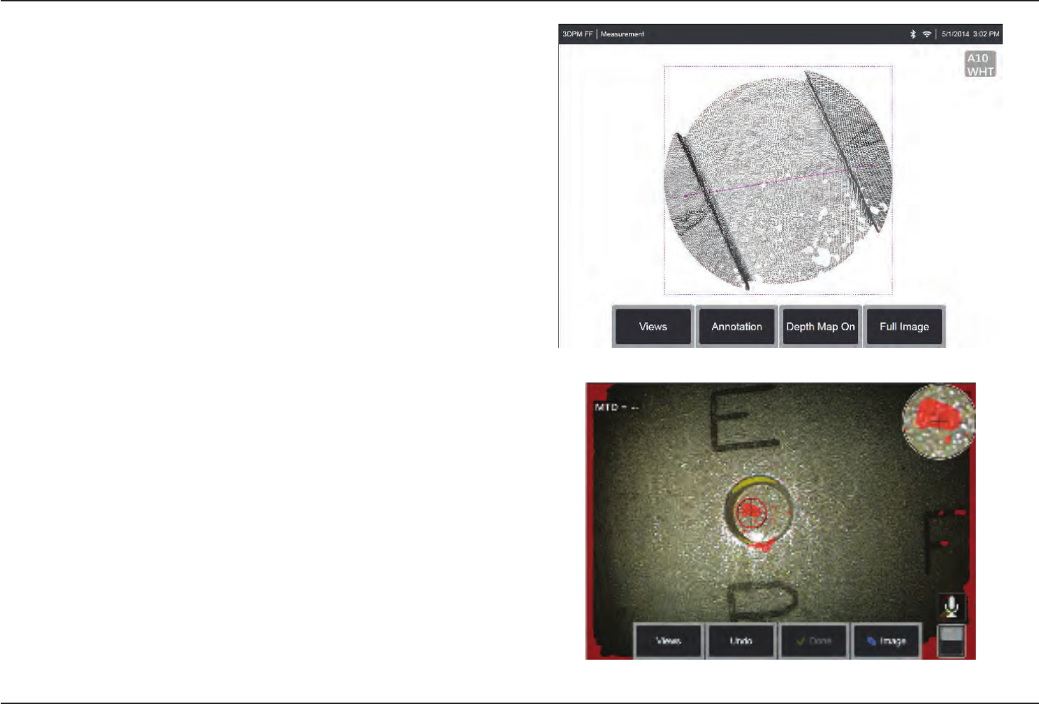
45
07/30/2014
Point Cloud View (3DPM)
The point cloud view oers the following advantages:
• Provides a rough idea of feature size.
• Shows location of high and low points to help prole and depth measurement cursor
positioning.
• Shows the level of noise relative to indication size. You can then move the probe closer
if indication is hidden in surface noise bumps.
• Ripple or waves indicate dirt or oil on the gratings or reections bouncing off one
surface onto another.
• When entered with no measurements placed, you can see the entire captured surface.
When the Point Cloud view is selected for an image with at least one measurement placed
(all apply to the measurement that is active when Point Cloud is selected):
- only the area around the active measurement is shown (unless Full View is selected)
- a reference plane is created using the measurement cursors
- the cursor positions and the lines between the cursors are shown
- for prole measurements, the prole slice along the surface and the line between the
two cursors are shown
- a square around the data, indicating the reference plane position, is shown
- a scale indicates the depth or height relative to the reference plane
Note—Indication of Non-Measurable Area
When working with a 3D phase measurement image, certain parts of the image may
not be measurable. These parts may be too far away, or be too dark, or obscured by
light reections if the surface is highly reective. The 3D Phase Measurement system
will display a red colored zone in those areas. To enhance measurement accuracy, the
system will not allow an operator to place cursors in a red colored area. The 3D Phase
Measurement system will display a yellow colored zone in those areas where accuracy
is reduced. Cursor placement in a yellow colored area should be avoided if possible.
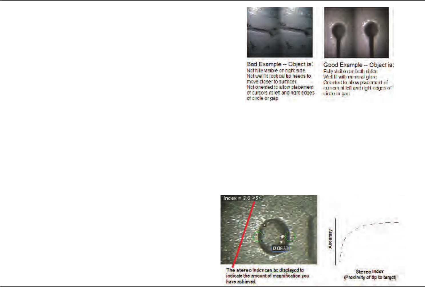
46 07/30/2014
Stereo Measurements
Stereo measurements require the use of StereoProbe measurement tips to capture
stereoscopic images of a target — two pictures of the same target from two different
angles. To measure the target, the Visual iQ uses triangulation based on these two
side-by-side images. You can take stereo measurements on a frozen image or on a
recalled image, provided the recalled image was acquired with a StereoProbe. The
Stereo Measurement process includes (see following sections for details):
Step 1 – Attaching a calibrated Stereo Tip
Step 2 – Capturing an acceptable view with a suitable Stereo Index.
Step 3 – Identifying the attached optical tip, selecting desired measurement type and
placing measurement cursors.
Step 4 – Properly positioning the Matching Cursors
Achieving a Suitable Image for Making Stereo Measurements
For maximum accuracy in any type of stereo measurement, you must begin by
positioning the stereo tip carefully. To position the probe tip (before freezing) for a
Stereo Measurement Image:
Visibility—The feature must be fully visible on both sides of the screen.
Tip-to-target proximity—The tip must be as close as possible to the target while
keeping it in focus.
Minimal glare—Minimize glare by adjusting the viewing angle and the image
brightness in the areas where you will be placing cursors. Small glare speckles do not
present a problem, but larger glare areas may appear in different positions on the
two sides, causing false matches.
Vertical orientation—If measuring distance between lines or across a circle, the
image is oriented so that you can place cursors at left and right edges of the
item to be measured — not at top, bottom or diagonal points. The system needs
differentiated details to the left and right of each cursor to accurately place the
matching cursors in horizontal relationship to the left-side cursors.
The images above represent good and bad image capturing techniques when
stereo measurements will be made. Both images were captured for length
measurement across the slot.
About the Stereo Index
The stereo index is a number that indicates the amount of magnication during stereo
measurements. The higher the stereo index, the greater the magnication, the more
accurately you can place the measurement cursors and the more accurate your results.
When taking stereo measurements, you magnify the image not by zooming but by
moving the optical tip as close as you can to the target. The stereo index can be turned
ON or OFF and the minimum value (below which it ashes) can be altered. Click here to
learn about adjusting the Stereo Index Limit and other Measurement Settings.
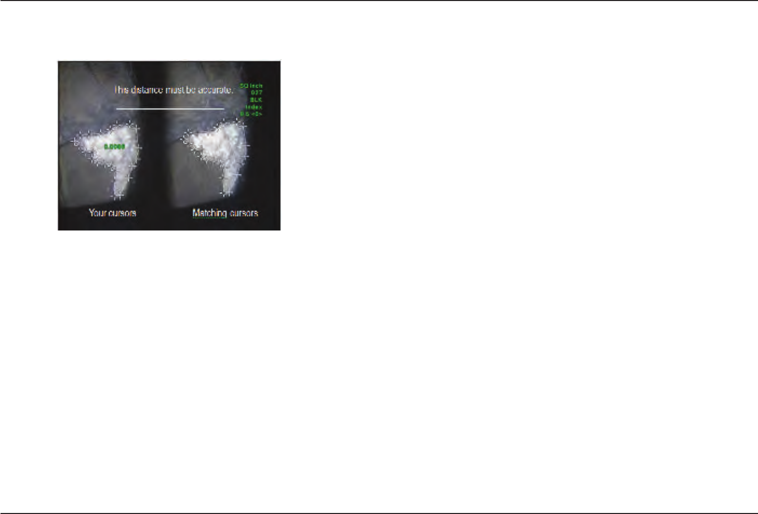
47
07/30/2014
About the Matching Cursors
For each cursor you place on the left image during stereo measurement, the system
places a matching cursor on the right image for use in triangulation.
You must place each left cursor on an image point (a pixel) that has sufcient
surrounding detail to differentiate it from its neighboring pixels. If the neighboring
pixels look the same as the point you choose — especially the pixels to the point’s left
and right, for example, pixels along a smooth horizontal line — the system cannot
accurately place the matching cursor. When there is enough differentiating detail,
the “match strength” is high (meaning that the generated match point clearly
matches better than its neighboring pixels — the system’s condence in the match
is high). But if there is not enough detail, the match strength is low (meaning that the
generated point and its neighboring pixels match almost equally well — the match
may be correct, but the system’s condence in the match is low).
For every matching cursor, the system calculates a match strength value between
<0> (lowest condence) and <5> (highest condence). If too little detail is present,
the system simply does not generate a matching cursor. Whenever possible, try
to achieve a match strength of at least <3>. If you cannot achieve this level, try
capturing another image with less glare or more image details. (Adjust the tip
orientation or image brightness.)
Even when match strength is <5>, and especially when the match strength is
lower, you need to verify that the matching cursor appears to be placed properly. A
matching cursor that is off by just one pixel can signicantly impact measurement
accuracy.
Repositioning a Matching Cursor
Note: Misplaced matching cursors most likely occur when the measurement area
contains a repeating pattern. Generally, the best results are achieved by leaving
the matching cursors exactly where the system places them.
Move the matching cursor to the correct position.
When you stop moving the cursor, the system optimizes the match position. Each
manually corrected matching cursor is indicated by the absence of a match strength
number.
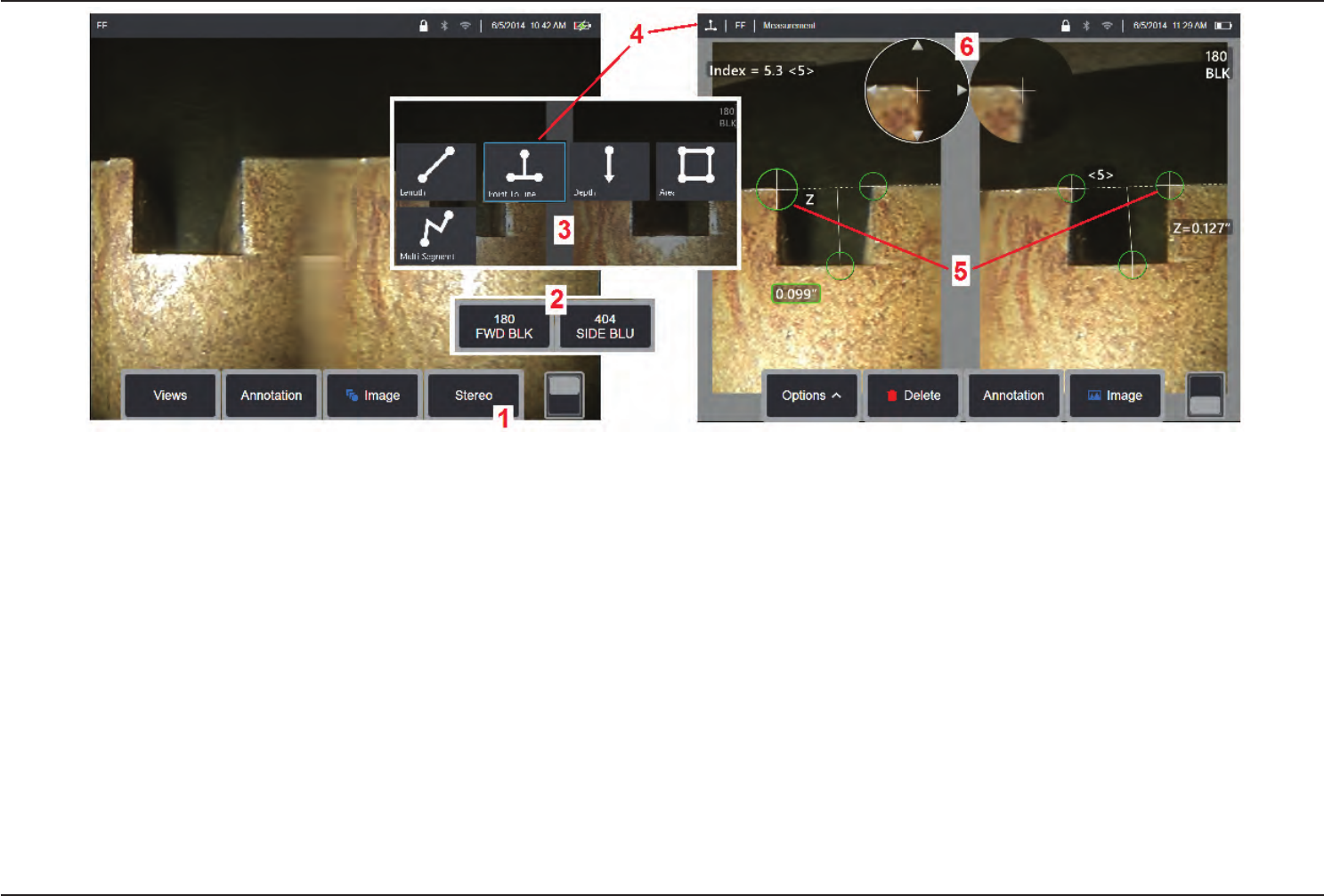
48 07/30/2014
Stereo Mode Measurement Procedure, Part 1
Prior to collecting stereo measurements, a calibrated stereo optical tip must be attached to your Visual iQ. Properly position the tip for measurement (click here to see how to
position the tip), which may be aided by temporarily displaying a single image by turning Single View mode ON (click here to select Single View and learn about other Image
Transformation settings). The image and cursor placement process is described in the sections above – you must become familiar with this information before conducting
stereo measurements.
1 – Select the Stereo soft key (if working with a frozen image) or the Measure soft key (if working with a recalled image captured with a stereo optical tip). Live stereo (and all other)
images must be frozen prior to beginning the measurement process. Be sure to select the soft key showing the serial number of the attached tip.
2 – After selecting Stereo, soft keys on the iQ’s display show the serial numbers for all stereo tips that have been calibrated to the installed probe. Be sure to select the serial
number of the tip currently installed. If, after collecting images for measurement, you determine that the wrong serial number was selected, refer to items 10 and 11 on the next
page of this manual.
3 – Begin the measurement process by choosing the type of measurement desired (see description of each type below)
4 – When a measurement type is selected (in this case, a Point-to-Line measurement), this icon describes the type chosen.
5 – First cursor appears on the left screen, where all user-placement of cursors will occur (the matching cursors appearing in the right display are generated by the Visual iQ system
– as the user moves each left-screen cursor, the matching cursor in the right half-screen moves accordingly – be sure to inspect each matching cursor as it appears). Drag with
your nger (or joystick) to position the active cursor to the desired location. This cursor can be reactivated (active cursor appears larger than other cursors) and moved at any time
(see additional screen features described below).
6 – Patented Zoom Window allows for precise positioning of the active cursor. Tap the window's edges (or move the cursor with the joystick) to adjust the active cursor position.
(ClickheretolearnaboutturningtheZoomWindowonoroandotherMeasurementSettings).
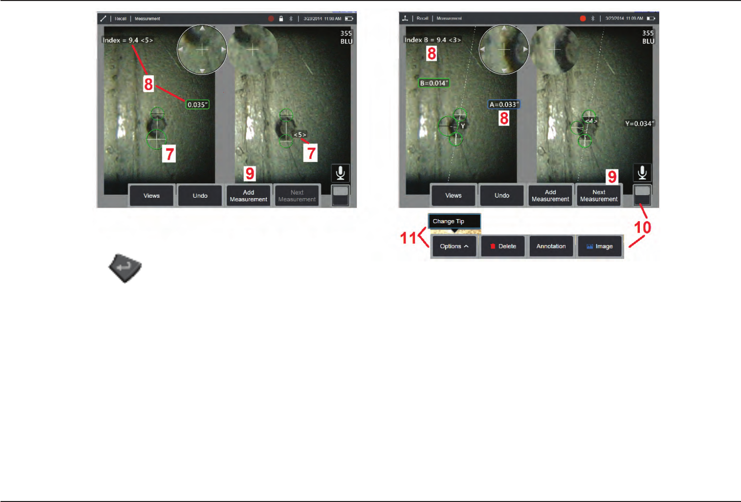
49
07/30/2014
Stereo Mode Measurement Procedure, Part 2
7 – Tap the screen (or hit ) to display the second cursor. Position it as described in items 5 and 6.
Note: Generally, you get the best results by leaving the matching cursors exactly where the system places them. However, under certain circumstances, such as when a repeating
pattern exists, you may need to help the system nd the correct match.
8 – The active dimension appears on the display screen (tapping the number turns its box blue and allows it to be repositioned) along with the Stereo Index and Match Strength
associated with this measurement and cursor placement. See the immediately preceding manual sections for a description of these two concepts.
9 – Select to Add another measurement (up to ve are allowed on any display). Once more than one measurement are displayed, select Next Measurement to change which
measurement is active (or simply tap on any existing measurement cursor to make it active).
10 – Tap to access alternate rows of soft keys. Double tapping in this location hides or displays the soft keys and status bar.
11 – Select Options, then Change Tip to retain the image captured and measurement(s) performed while correcting for an incorrectly specied tip serial number. This process
allows the correct calibration data to be applied and eliminates the need to collect additional images simply because the user initially identied the wrong tip serial number.
Note: The Stereo Index and Match Strength shown apply only to the active measurement.
Note: To verify your measurement accuracy, move each left-side cursor a few pixels. If the matching cursors move identically, and if the results change only a little, you have
probably achieved accurate results. But if a matching cursor’s movement is erratic, or if the results change signicantly, your results are unreliable. capture a fresh image, following
the guidelines above. This step is especially useful if you have to use a low Stereo Index (less than 5) or low condence number (less than 3). For example, you might have to use
a low Stereo Index if you are measuring a large object or if you have limited access and cannot bring the tip close to the target. You might have to accept a lower condence
number if the surface has few details.
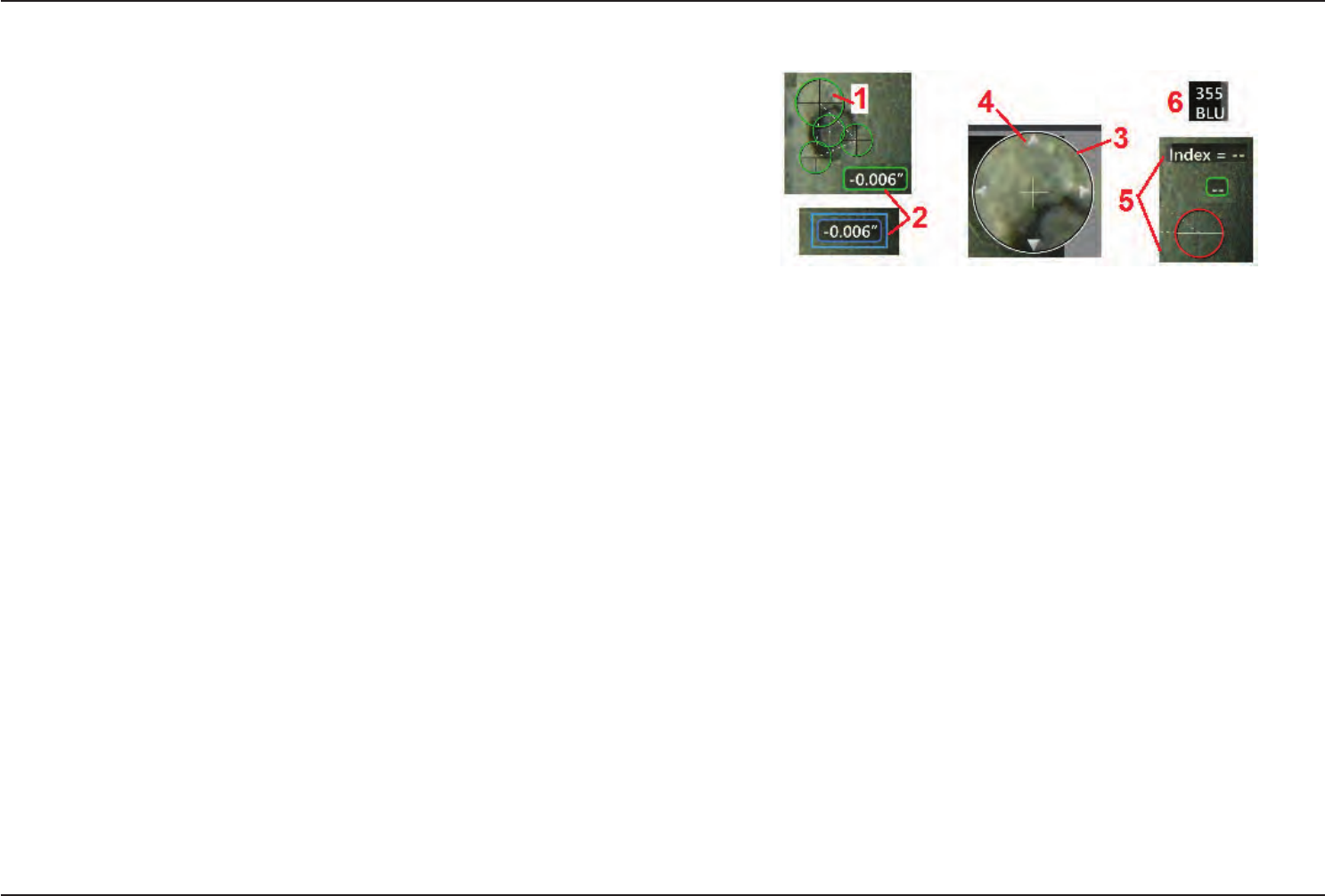
50 07/30/2014
Features of the Stereo Measurement Screen
1 – The currently active cursor appears larger than all others. Note that this cursor’s
position can be altered by the joystick or by dragging it across the screen.
2 – Tap any on-screen dimension to select it for repositioning (by dragging or with
joystick)
3 – The highlighted Zoom Window allows for precise positioning of the active cursor.
Select and drag it to change its location on the display screen.
4 – Tap on these arrowheads near the perimeter (or use the joystick) to move the
cursor.
5 – Any cursor positioned where a lack of image detail prevents the system from
nding a matching point changes color to red (and all dimension and index numbers
revert to dashes).
6 – The type and serial number of optical tip currently selected (click here to identify
and/or calibrate stereo tips)
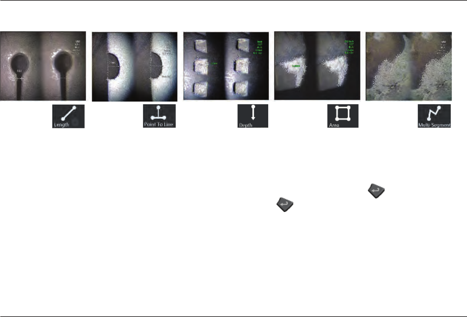
51
07/30/2014
Stereo Measurement Types
This section specically addresses cursor placement for each type of stereo measurement.
Description:
Linear (Point-to-
Point)
Cursor Placement:
Place both cursors
Description:
The perpendicular
distance from a
point to a line
Cursor Placement:
Place the rst two cursors to
dene a reference line. Place the
third cursor at the perpendicular
distance you want to measure
Description:
The perpendicular
distance between a
surface and a point
above or below it.
Used to evaluate changes due to
wear, misalignment, and other
causes.
Negative measurements indicate
that the point lies below the plane.
Positive measurements indicate
that it lies above
Cursor Placement:
Place the rst three cursors to
dene a reference plane. Place the
fourth cursor at the perpendicular
distance you want to measure.
Note: Depth measurements
taken at a low accuracy index
are particularly sensitive to the
matching cursor’s position. If the
accuracy index is low, increase it
by bringing the probe tip closer. If
you cannot increase the accuracy
index, place cursors so that they
yield high match strengths, and
verify your accuracy.
(Click here to learn more about the
Stereo Mode Measurement Procedure).
Description:
The surface
area contained
within multiple
cursors placed around a feature or
indication.
Cursor Placement:
Place three or more cursors (up to
24) around the edge of the area
you want to measure.
When nished, select Done or press
twice. The area closes.
Description:
The length of a
nonlinear feature
or indication.
Cursor Placement:
Place two or more measurement
cursors (up to 24) to create
segments along the feature.
When nished, select Done or press
twice. The line is nalized.
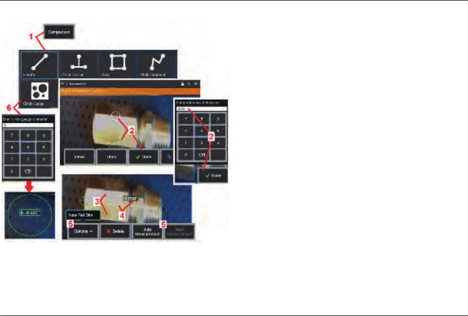
52 07/30/2014
Comparison Measurements
Comparison measurements rely on the known dimensions of an object that has been
set in the eld of view either by the manufacturer or by the probe or takes advantage
of known dimensions within the frozen image. The Visual iQ processor uses these
known dimensions as a reference scale for measuring an unknown target. You can take
comparison measurements on a frozen (non-3DPM) image or on a recalled image that
was saved in Comparison measurement mode.
Making a Comparison Measurement
Use the head guard or attach any standard forward-view or side-view tip to the probe.
Select the Field of View (FOV) for your tip from the soft key or the touch screen. This
allows the system to improve accuracy by compensating for the tip's optical distortion.
If FOV is not known consult Appendix B. Position the probe tip for maximum accuracy,
by making the surface to be measured appear perpendicular to the probe view. The
target and known object should both be in the same plane at the same distance from
the probe with the tip as close as possible while tting them both fully into the image.
If the object and reference are small on the screen, zoom in. Freeze the display before
beginning the measurement process.
1 – Select to launch the Comparison measurement mode. Begin by selecting the
measurement type. Click here to view a table describing each measurement type.
2 – A reference of known length must next be input by placing two cursors and dening
the reference length.
3 – The reference length cursors remain.
4 – Arrange measurement cursors to determine the unknown dimension. In this case,
the system is performing a Length measurement. Click here to view a table describing
each measurement type.
5 – Select to input a New Reference Dimension, Add another measurement (up to 5), or
change the active measurement (by selecting Next Measurement).
6 – Once a reference length is dened, a circle of known diameter can be displayed on
the image by selecting this option. The circle gauge may be used as a “go/no-go” gauge
when its diameter is set to a defect size limit.

53
07/30/2014
Troubleshooting Measurements
Inaccurate 3D Phase or Stereo Measurements
• Move the probe tip as close as possible to the target, maximizing magnication.
• After capturing an image, verify that the tip attached to the probe matches the tip that is selected in the software. Click here to learn more about managing probe tips.
Note: The user-input tip serial number appears in the measurement screen’s corner.
• Verify that you have selected the correct type of measurement for the probe installed.
• Verify that the optical tip is threaded on to the probe head securely.
• Measure the target contained in the verication block to ensure that no tip damage has occurred. Click here to learn more about Verifying Measurement Tips.
Inaccurate 3D Phase Measurements
• Be sure to hold the probe still for approximately one second during the surface scan. Do not move the probe until after the Processing message appears on-screen.
• Reposition the probe tip until the range nder bar pattern on the Live screen shows the maximum possible number of green bars. It is acceptable to be slightly out of focus
for very small indications.
• Make sure all measurement-tip surfaces are clean. Wipe with a clean cloth and alcohol.
• Try a non-perpendicular view, such as 30-45°. This often signicantly decreases the noise level in the data, especially for surfaces that are shiny or have a speckled appearance.
• Check with verication block. Check point cloud view for excessive waviness or ripple, which would indicate dirt or oil contamination or tip damage
Inaccurate Stereo Measurements
• Avoid placing cursors in areas of signicant glare. If necessary, adjust the brightness or reposition the probe tip to enhance details and reduce glare.
• Verify that the object to be measured is near the center of the screen.
• Verify that the matching cursor is correct within 1 pixel. If you cannot clearly see where the match point should be, select a different point, or capture the image from a different
angle that better reveals details to allow better matching.
• Activate the zoom window to most accurately place the measurement cursors.
• Review guidelines under Achieving a Suitable Image for Making Stereo Measurements
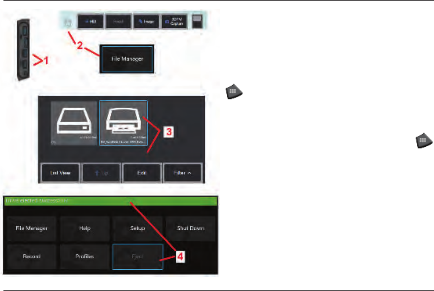
54 07/30/2014
Managing Files
Working with Removable Storage Devices
USB storage devices can be connected to the iQ, accessed through its File Manager,
written to and copied from, and Ejected using the features described here.
1 – Insert the USB Storage Device into either of these ports.
2 –To access les or folders on the USB drive, tap the on-screen GE Logo (or press the
hard key) to open the Global Menu, then select File Manager.
3 –Select the USB device, then navigate, access les or folders, and write to or copy from
the drive as you would work with he iQ’s internal memory. Click here to learn more
about working with the File Manager.
4 –Before removing the USB drive, tap the on-screen GE Logo (or press the
hard key) to open the Global Menu, then select Eject. It will be safe to remove the drive
once this message appears on the display.

55
07/30/2014
Editing Files and Folders/Creating Folders
Image and video les can be stored in the Visual iQ or a detachable device. The File
Manager feature allows these stored les (or the folders in which they are stored) to
be Copied, Cut, Pasted, Deleted, Renamed, or Created (in the case of folders). Follow
these steps to Edit les or folders:
1 – To edit les or folders, tap the on-screen GE Logo (or press the hard key) to
open the Global Menu, then select File Manager. Alternatively, select the Recall soft
key (when enabled), which allows you to recall a stored image or video and/or edit les
and folders. To Create a New Folder, rst access the File Manager, then navigate to
the drive location where you want to create the new folder and proceed to Item 5 below
for additional instructions.
2 – Controls the File Manager’s appearance (Thumbnail View shown here).
3 – Select to navigate to the next higher directory within the File Manager.
4 – Choose which le types to display.
5 – Tap to switch between the Soft Key Bar’s top and bottom row. To Create a New
Folder, select Create Folder from the bottom row and proceed to Item 9 below for
additional instructions. Double tapping in this location hides or displays the soft keys
and status bar.
6 – Select to turn on the le Editor function, which allows you to Copy, Rename, and
otherwise Edit stored folders (or les).
7 – Tap on a folder (or le) to select it for editing. The white check appears in the corner
of all selected folders or les.
Note: The Edit function must be activated and the le (or folder) selected – so that a
white check appears in its corner – before editing.
8 – Once selected for editing, the folder or le can be Copied (or Cut) and Pasted or
Deleted.
9 – Once selected, a folder (or le) can be Renamed. When renaming (or creating a new
folder), the virtual keyboard opens.
10 – Select to choose from numeric characters or symbols.
11 – Tap after typing the desired name.
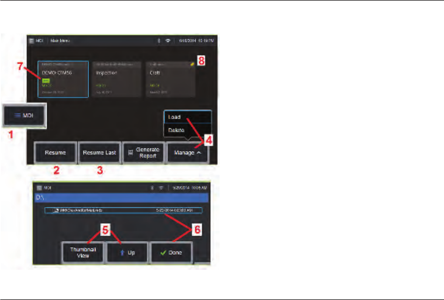
56 07/30/2014
MDI
Loading and Unloading Menu Directed
Inspections
Follow this process to load or unload a Menu Directed Inspection.
Note: MDI inspection les have the le extension of .mdz. A maximum of fty MDI
inspection les may be loaded at any given time.
1 – Select to launch the MDI process.
2 – Select to browse for and Resume a previously active inspection.
3 – Resume the Last active inspection.
4 – Load a new inspection or Delete an existing one.
5 – Navigate the File Manager to select a le to Load or Delete.
6 – Select to Complete the loading process.
7 – Indicates a newly loaded inspection.
8 – Indicates the last active inspection.
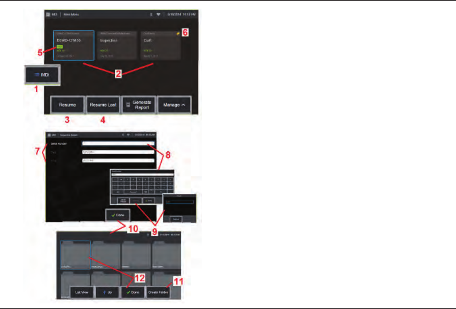
57
07/30/2014
Starting a Menu Directed Inspection
1 – Select to begin the MDI process.
2 – Select any loaded inspection.
3 – Select to browse for and Resume a previously active inspection.
4 – Resume the Last active inspection.
5 – Indicates a newly loaded inspection.
6 – Indicates the last active inspection.
Entering Study Level Information
At the start of an MDI inspection, you are prompted to enter the study level information
and to select the directory (folder) into which your inspection results will be saved.
7 – Study Level Information (varies for each MDI) is entered at the start of an inspection.
Information marked * is required before collecting results.
8 – To enter information, simply choose the corresponding line and the Virtual Keyboard
will automatically launch.
9 – Use the keyboard to enter information or choose from a user-generated set of
Preset entries.
10 – Select when nished entering all Study Level Information.
11 – You must then identify the Folder (directory) into which results acquired during the
MDI process are saved. Either Create a New Folder or choose an existing one.
12 – Select to complete the information input process.
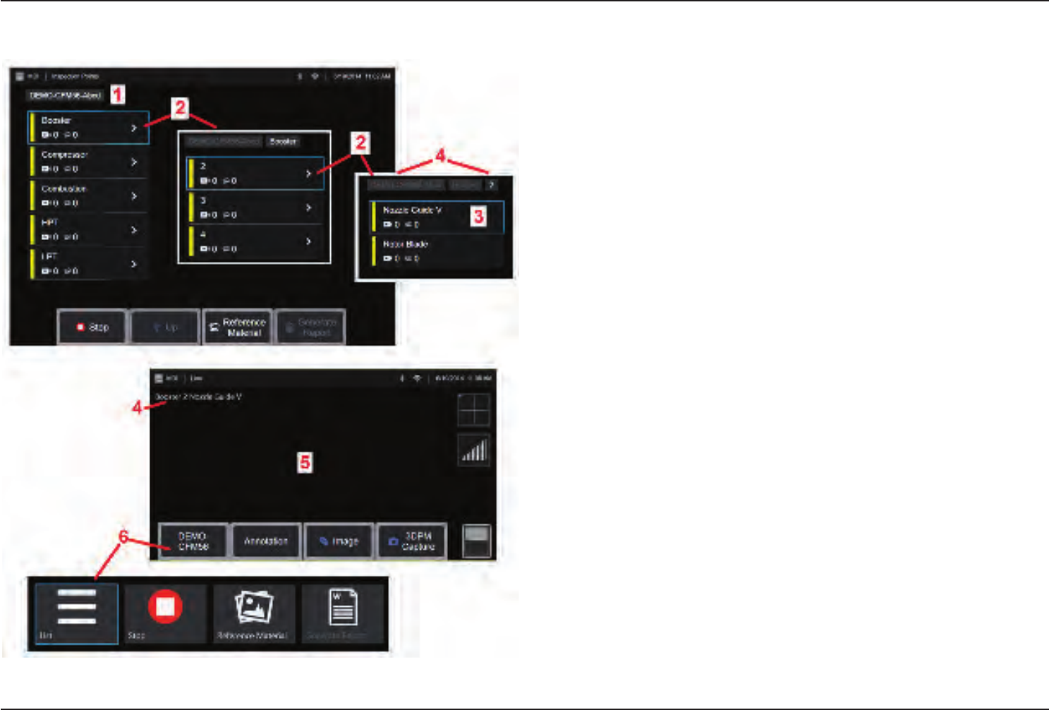
58 07/30/2014
Selecting an Inspection Point
At this time, you can navigate through the inspection levels until you have reached the
desired inspection point.
1 – Inspection name and equipment serial number.
2 – Select to navigate to the inspection’s next-lowest organization level.
3 – Navigating to the bottom level of the inspection allows you to record images and
videos.
4 – These labels indicate the level(s) within the inspection and identify your current
position.
5 – Click here to learn more about capturing images or Click here to work with videos.
6 – Select soft key labeled with the Inspection Name to access this MDI Leaf Menu. Use
this menu to navigate the List of inspection levels, Stop the current inspection, access
Reference Material related to the inspection, or Generate a Report listing the results
stored for the current inspection.
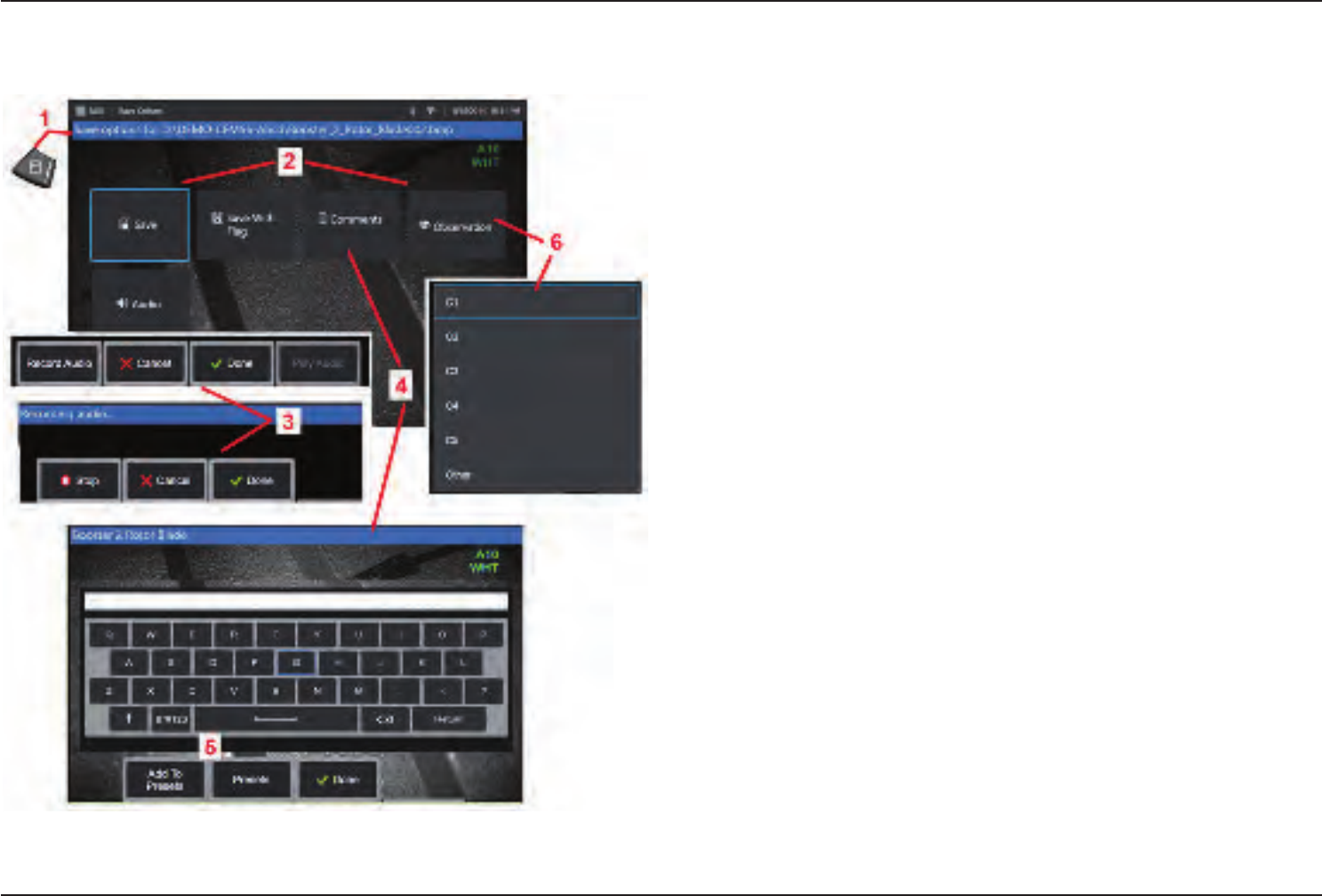
59
07/30/2014
Saving an Image or Video in an MDI Inspection
To save an image in the selected inspection point, press the SAVE hard key. During the
save process, some of the following are available:
Required Characterization - If required, a characterization list appears before the save
menu. You must select an entry to continue.
Save - Saves the image with the associated MDI data and lename.
Save with Flag - Saves the image with “FLAG” appended onto the lename. If you use
this option, you can then generate a report including only the agged images.
Observation - Assign characterization to this image.
Add Comments - Save typed comments along with the image. When generating a report,
these comments are associated with the specic image.
Add Audio Comments - Record audio comments along with the image.
1 – Press this hard key to save the frozen image into the selected inspection point.
Note: The system automatically names the image to correspond to the location in
the MDI le currently selected.
2 – Save Options are described above (not all appear in every MDI).
Note: Save (or Save With Flag) only after all Comments, Observations, or Audio
Comments are entered as this added information will then be associated with the
saved image.
3 – These menus allow the user to add Audio Comments to any image prior to saving.
Be sure to select Done to complete the audio-comment recording process.
4 – Select Comments to enter written comments to be saved with the image.
5 – Entered comments can be added to a list of Preset comments from which you can
later select.
6 – Choose Observations from a pre-loaded list
Note: Images and Videos saved using MDI are located in the inspection folder created
at the beginning of the inspection. The image or video le has Meta data associated
with it to ensure communication with data management software such as GEIT
Rhythm.
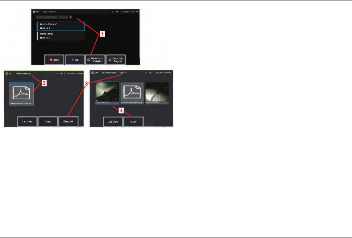
60 07/30/2014
Viewing Reference Material
1 – Select at any level within the inspection to access Reference Material associated
with the level or point
2 – Select any PDF, image, or video material to open and view on the Visual iQ display
3 – Select Show All to access all Reference Material associated with the active
inspection, which may be more than the material associated with the active level.
4 – Select to Copy and paste all reference material for the active inspection into the
folder identied at the beginning of the inspection for storage of results.
Stopping and Resuming an Inspection
To stop an inspection, which may be resumed or nished at a later time, access the MDI
Leaf Menu by selecting the soft key bearing the inspection’s name and select Stop. To
resume a previously stopped inspection, select the MDI soft key, then choose to either
Resume the Last inspection or browse for a previous inspection to Resume.
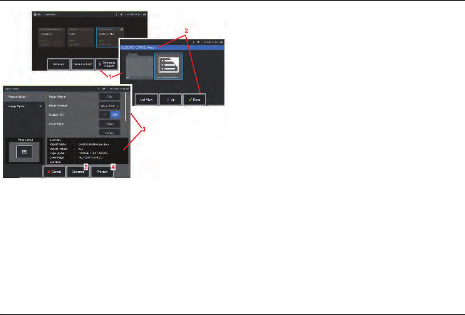
61
07/30/2014
Generating an MDI Report
Follow this process to generate an MDI report.
1 – Select to Generate a Report and, if no inspection is active, choose the desired
inspection.
2 – After selecting the inspection for which you wish to generate a report, choose Done.
3 – Report contents, page layout, and other features can be customized as described
in the next section of this manual.
4 – Preview the report on the Visual iQ display.
5 – Generate an MS Word version of the report, which will be saved in the folder identied
for this inspection.
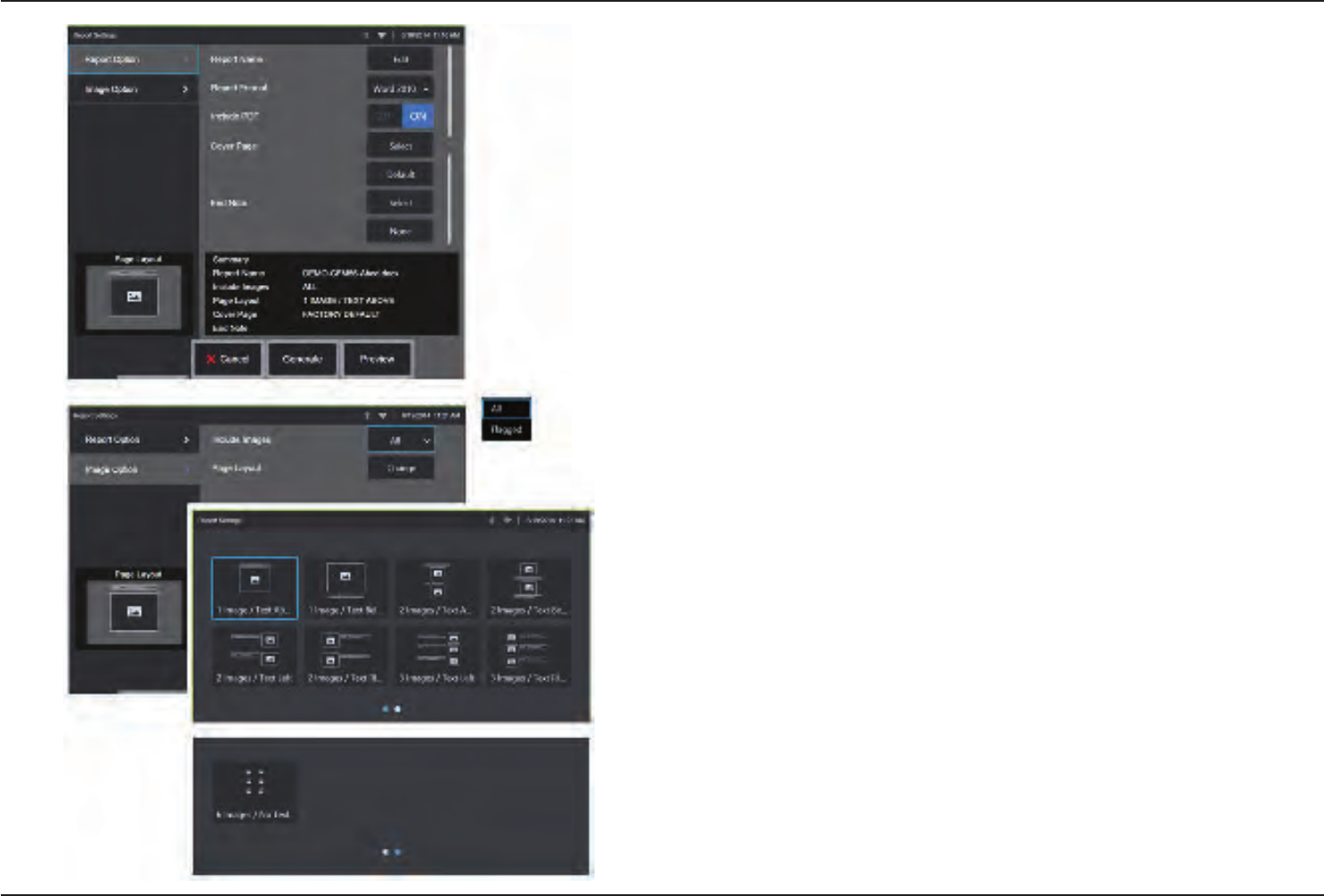
62 07/30/2014
Customizing an MDI Report
Customize an inspection report by specifying the following parameters:
REPORT OPTIONS:
• Report Name – Override the automatic inspection report le name.
• Report Format – Choose the version of MS Word in which to publish.
• Include PDF – Creates a PDF version of the report (can view on the Visual iQ display).
• Cover Page - Select the cover page to include in the inspection report.
- FACTORY DEFAULT - Use the factory default settings for all parameters.
- BROWSE - Select an MS Word doc to use as report cover page.
• End Note - Select the pages to include as the last pages of the report
- NONE - Don’t include any custom features in your inspection report.
- BROWSE - Select an MS Word doc to include as report end note.
IMAGE OPTIONS:
• Include Images - Select either all images or only agged images to be included in
the inspection report.
• Image Layout - Select from several styles of text and image layout or select No Text
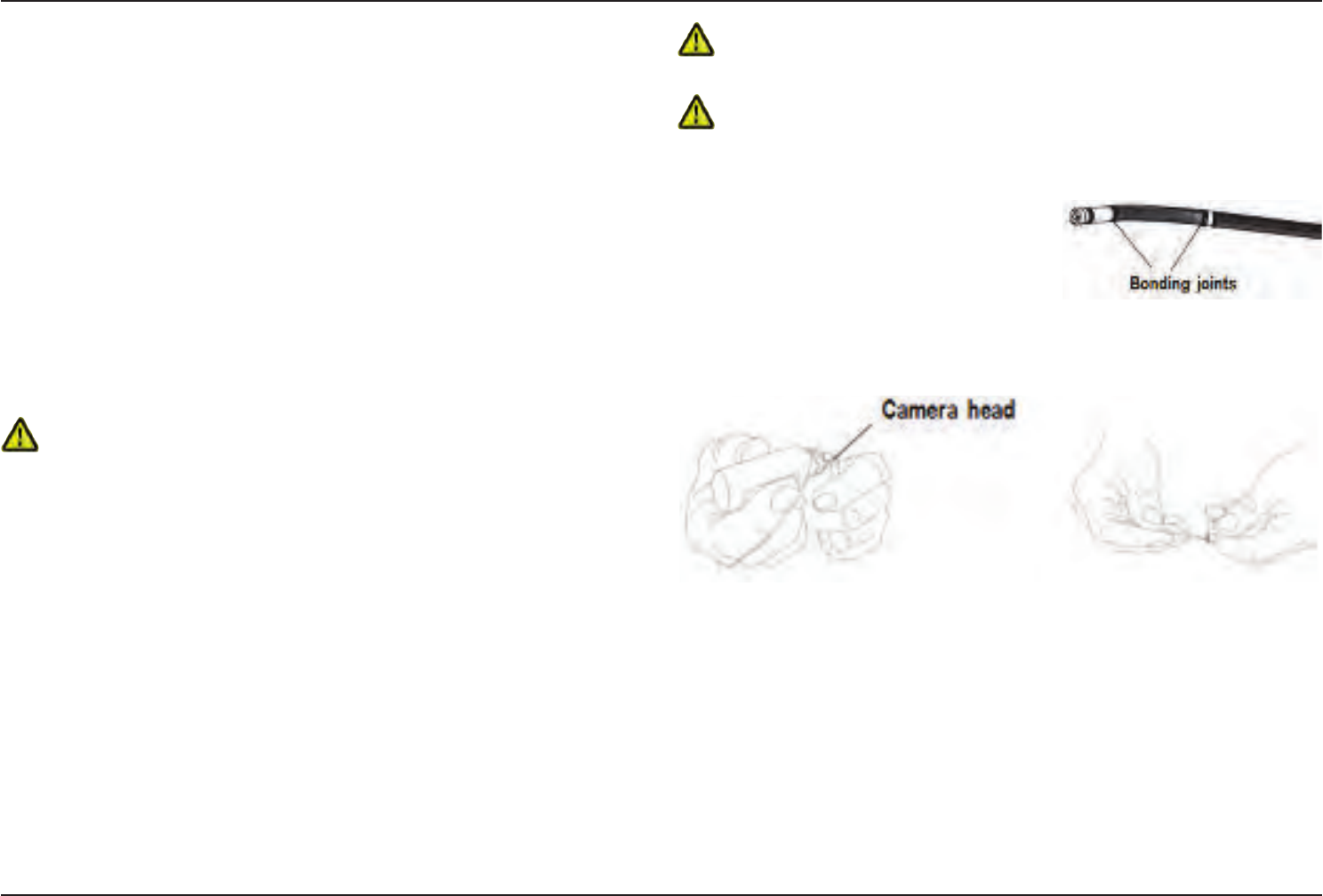
63
07/30/2014
Maintenance and
Troubleshooting
Inspecting and Cleaning the System
Inspect and clean the Visual iQ system before and after each use. If using the system in
a dirty environment, clean the components more frequently as needed.
If images are distorted or blurred within normal range, and if the optical tip is securely
threaded, the most likely problem is dirty optical surfaces. For best image quality, clean
the optical tip and camera head frequently.
If you discover conditions that require evaluation or repair, return the system to GE
Inspection Technologies. Early repair of minor conditions can prevent much more costly
repair.
Caution: Do not immerse or soak the handset or the probe power plug.
Inspecting and Cleaning an Optical Tip
1 – Check the optical tip for damage or contamination.
2 – Clean all external parts of the optical tip. Use glass cleaner or 70% alcohol-to-water
solution and a pointed cotton swab.
3 – Clean only the internal threads of the optical tip. The internal optical lens should only
be cleaned when troubleshooting an optical tip that provides poor focus.
Caution: The internal optical lens is surrounded by an O-ring. Use care not to
dislodge the O-ring.
Caution: Do not use a cotton swab to clean the inside of the 3D phase measurement
optical tips tip or damage to the tip may occur.
Inspecting and Cleaning a Probe
1 – Check the probe for damage or
contamination. Look for excessive wear
in the bending neck, loose strands of the
braided weave, or separation of the bonding
joints.
2 – Clean the probe tip, including the lens on the camera head. Use glass cleaner or
70% alcohol-to-water solution and a pointed cotton swab.
3 – Clean the rest of the probe, including insertion tube and beroptic connector. Use a
soft cloth dampened with glass cleaner or 70% alcohol-to-water solution.
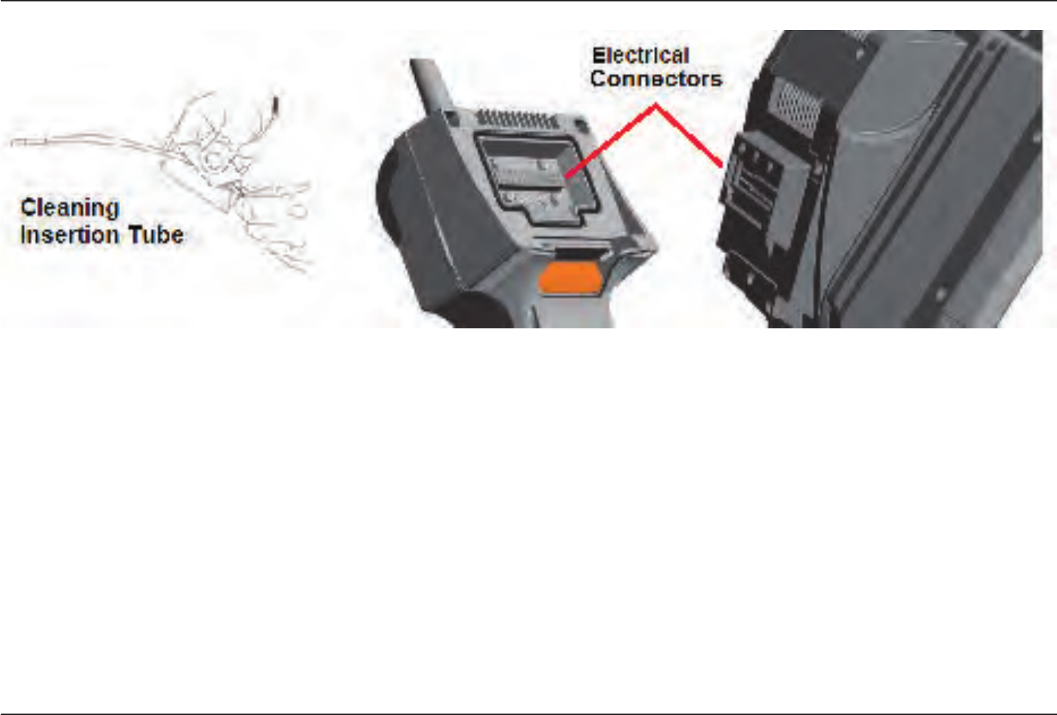
64 07/30/2014
Inspecting and Cleaning the Handset
1 – Disconnect the power cord from the power source.
2 – Check for damage or contamination, including any bent pins on the electrical connector.
3 – Use a soft cloth dampened with glass cleaner or 70% alcohol-to-water solution to clean all parts of the handset, except the electrical connector. Use great care when cleaning
the electrical contact pins of the connector. Carefully clean the contact pins with glass cleaner or 70% alcohol-to-water solution using a cotton swab. Compressed air may be used
to dry or remove debris from the electrical connector.

65
07/30/2014
Troubleshooting Guide
Image
Condition Causes Actions
Images are distorted or
blurred within normal
range.
• Optical tip is not threaded
onto the camera head
securely.
• The optical surfaces are dirty.
• No tip optic or head guard is
installed on camera tip.
Reinstall the optical tip. See “To Attach an Optical Tip”
• Clean the optical tip and the camera head. See “Inspecting and Cleaning an Optical Tip” and “Inspecting and Cleaning a
Probe”
• The Visual iQ 6.1mm diameter probes require the use of the 6.1mm headguard supplied. This headguard is unique to the
Visual iQ 6.1mm in that it contains an aperture unlike previous product generations.
• Remove the tip optic.
• Try a different tip optic.
Image quality is otherwise
poor.
Various • If available connect a different probe to handset.
• If image quality issue is associated with a specic probe contact GE Inspection Technologies to obtain a return material
authorization (RMA).
No image appears in the
display.
(Hard Keys are lit)
Various • Verify that the probe is properly seated and latched. See “To Install a Probe”
• Reboot system.
• If available connect a different probe to handset.
• If image quality issue is associated with a specic probe contact GE Inspection Technologies to obtain a return material
authorization (RMA)
• Point the probe tip toward a bright light and see if image appears. If image appears, the problem is associated with lamp
operation. If still no image, contact GE Inspection Technologies to obtain a return material authorization (RMA).
• If a Displayport cable was purchased connect to a Displayport capable monitor. Determine whether an image appears on it.
Dark video image Various • Clean the optical tip and the camera head. See “Inspecting and Cleaning an Optical Tip” and “Inspecting and Cleaning a
Probe”
• Verify the LCD Brightness is properly adjusted for the ambient condition.
• Check the insertion tube and bending section for severe kinks or dents.
• No LED operation
Frozen image “jitters” or is
blurred.
• Probe tip was moving when
image was captured.
• Unfreeze then refreeze the image, keeping probe tip steady.

66 07/30/2014
Probe
Condition Causes Actions
Reduced articulation in the
bending neck.
Bending neck is not
articulating.
• System is in an articulation-
disabling mode such as
Steer-and-Stay, freeze frame,
File Manager, or any Menu
function
• Exit the articulation-disabling mode.
• Power down the Visual iQ. Leave the system off for at least 15 seconds so that it can complete its shutdown sequence. Then turn
it back on.
Insertion tube does not
freely withdraw from the
storage reel.
• Insertion tube is stuck. • Gently push the insertion tube in and out with a slight twisting motion in order to free the probe. If probe cannot be freed
contact GE Inspection Technologies Tech Support.
Handset
Condition Causes Actions
Odd behavior or limited
functions.
Various • Reboot system.
Reduced light output • High-temperature operation
will cause system to
automatically limit LED power.
• No fan operation
• If reduced light output is acceptable, normal use may continue. If greater light output is required, power system down and allow
to cool.
• Verify that both fans are operating. Clean with compressed air to remove dirt, and debris.
Reduced system response
speed
• High-temperature
operation will cause system
to automatically limit
Microprocessor power.
• No fan operation
• If reduced processing speed is acceptable, normal use may continue. If greater processing speed is required, power system
down and allow to cool.
• Verify that both fans are operating. Clean with compressed air to remove dirt, and debris.
Automatic over-temp
shutdown
• Over-temp shutdown
• No fan operation
• Allow system to cool adequately prior to power-up.
• Verify that both fans are operating. Clean with compressed air to remove dirt, and debris.
Erratic touchscreen
behavior
• Lack of grounded AC power • Remove charger from handset to determine if erratic behavior is caused by AC charger.
• Connect charger to known “good” grounded outlet.

67
07/30/2014
Power
Condition Causes Actions
When plugged into AC power, system will
not charge.
• No AC power present
• Incorrect charger
• Defective charger
• Check AC power source.
• Check power cable connections.
• Verify the correct charger is marked with 100 – 240V AC 50/60Hz 18VDC 3.34A.
• Contact GE Inspection Technologies for a replacement charger.
When plugged into AC power, system will
not turn on.
• Incorrect charger
• Defective charger
• Defective Battery
• Verify the correct charger is marked with 100 – 240V AC 50/60Hz 18VDC 3.34A.
• Contact GE Inspection Technologies for a replacement charger.
• Try another battery.
• If replacement battery does not restore operation contact GE Inspection Technologies to obtain a return material
authorization (RMA).
System runs when connected to AC
power only. • Battery disconnected or
incorrectly connected.
• Battery low, not charging,
depleted or defective.
• Disconnect and reconnect battery.
• Verify battery charge level.
• Recharge or replace the battery.
Software
Condition Causes Actions
Time, date, or other settings are lost
when system is turned off.
• Internal battery needs
replacing. (Normal life is ve
years.)
• Return system to GE Inspection Technologies to have internal battery replaced. Contact GE Inspection
Technologies to obtain a return material authorization (RMA).

68 07/30/2014
APPENDICES
Appendix A. Technical Specications
Operating Temperature
Tip -25ºC to 100ºC (-13ºF to 212ºF). Reduced articulation below 0ºC (32ºF)
System -20º to 46ºC (-4ºF to 115ºF). LCD may require warm-up period below 0ºC (32ºF).
Storage Temperature -25º to 60ºC (-13ºF to 140ºF)
Relative Humidity 95% max, non-condensing
Waterproof Insertion tube and tip to 14.7 psi (1 bar, 10.2 m of H2O, 33.5 ft of H2O).
Hazardous Environments Not rated for use in hazardous environments.
Camera
Diameter Probe 4.0 mm (0.16”), 6.1 mm (0.24”),
Image Sensor 1/6” Color SUPER HAD™ CCD camera (6.1) 1/10” (4.0 mm)
Pixel Count 440,000 pixels
Housing Titanium
System
System Dimensions 17.1 x 33.8 x 87.1 cm (6.75 x 8 x 15”)
Case Dimensions (Standard) 48.8 x 38.6 x 18.5 cm (19.2 x 15.2 x 7.3”)
System Weight In small case with contents: 10.2 kg (22.4 lbs). In large case with contents: 19.6 kg (43.2 lbs).
Out of Case: 6120 system - 3.0 kg (6.7 lbs). 6110 system - 4.0 kg (8.7 lbs).
Construction Magnesium and Polycarbonate housing with integrated elastomeric bumpers
LCD Monitor Integrated (6.5”) active matrix XGA color LCD, daylight readable display, with optically-
bonded, multipoint capacitive Dragontrail™ touchscreen.
Joystick Control 360º All-Way® tip articulation, menu access, and navigation
Button Set Access user functions, measurement, and digital functions
Audio Integrated 3.5mm headset / microphone jack or bluetooth headset
Internal Memory 16 GB SSD for user storage
Data I/O Ports Two USB 3.0 host ‘A’ ports, one USB 3.0 client micro ‘B’ port,
Video Out DisplayPort

69
07/30/2014
Brightness Control Auto and Variable
Illumination Type White LED
Long Exposure Auto - up to 16 seconds
White Balance Factory default or user dened
Wi-Fi Adapter 802.11a/b/g/n/ac, dual-band (2.4GHz/5GHz), 2x2
Bluetooth Adapter Bluetooth 4.0
Power
Lithium Ion Battery 10.8V (nominal), 73Wh, 6.8Ah
Power Supply
AC 100-240VAC, 50-60Hz, <1.5A RMS
DC 18V, 3.34A
StandardsComplianceandClassications
MIL-STD-810G United States Department of Defense Environment Tests Sections 501.5, 502.5, 506.5,
507.5, 510.5, 511.5, 514.6, 516.6, 521.3
MIL-STD-461F U.S. Department of Defense -- Electromagnetic Interference RS103, RE102 - ABOVE DECK
Standards Compliance Group 1, Class A: EN61326-1, UL, IEC, EN CSA-C22.2:61010-1, UN/DOT T1-T8
IP Rating IP55 (Disassembled), IP67 (Assembled)
Patent Information
Mentor Visual iQ is covered under one or more of the following US Patents: US5734418, US5754313, US6468201, US7819798,
US8310533, US8368749, US7262797, US7782453, US8514278, US8213676, US7821649, US8107083, US8422030, US7969583,
US8253782, US7902990, US8310604, US8165351, US8760447, US8411083.
Software
Operating System Embedded, multi-tasking operating system
User Interface Menu-driven and soft button operation; menu navigation using either touchscreen or joystick
File Manager Embedded le manager supports the following operation on les and folders: copy, cut,
create, rename, delete, lter and sort. USB and internal ash storage.

70 07/30/2014
Audio Data PC compatible AAC (.m4a) le format
Image Control Invert, Inverse+, Adaptive Noise Reduction, Distortion Correction, Illumination, Brightness,
Long Exposure, Single View, Zoom (5x digital), Image Capture and Recall
Digital Zoom Continuous (5x)
Image Formats Bitmap (.BMP), JPEG (.JPG)
Video Format MPEG4 AVC /H.264 (.MP4)
Text Annotation Built-in full-screen text overlay generator
Graphic Annotation User placement of arrows
Articulation Control User-selectable steer vs. steer & stay articulation; tip “Home” return to neutral forward-tip
orientation.
Software Updates Field upgradable via USB ThumbDrive®
Languages English, Spanish, French, German, Italian, Russian, Japanese, Korean, Portuguese, Chinese,
Polish, Hungarian, Finnish and Swedish
Application Software Menu Directed Inspection (MDI) software digitally guides inspectors through the inspection
process, intelligently names les and creates MS Word® and PDF compatible inspection
reports.
Probe Measurements
Diameter Length
4.0 mm (0.15”) 2.0, 3.0 m (6.6, 9,8 ft.)
6.1 mm (0.24”) 2.0, 3.0, 4.5, 6.0, 10.0 m (6.6, 9.8, 14.8, 19.7, 32.8 ft.)
Longer lengths up to 30 m are available. Contact your sales representative for details.
Tip Articulation
Insertion Tube Length Articulation
2 m - 4.5 m Up/Down 160° min, Left/Right 160° min
6 m – 10 m Up/Down 140° min, Left/Right 140° min
Note: Typical articulation exceeds minimum specications.
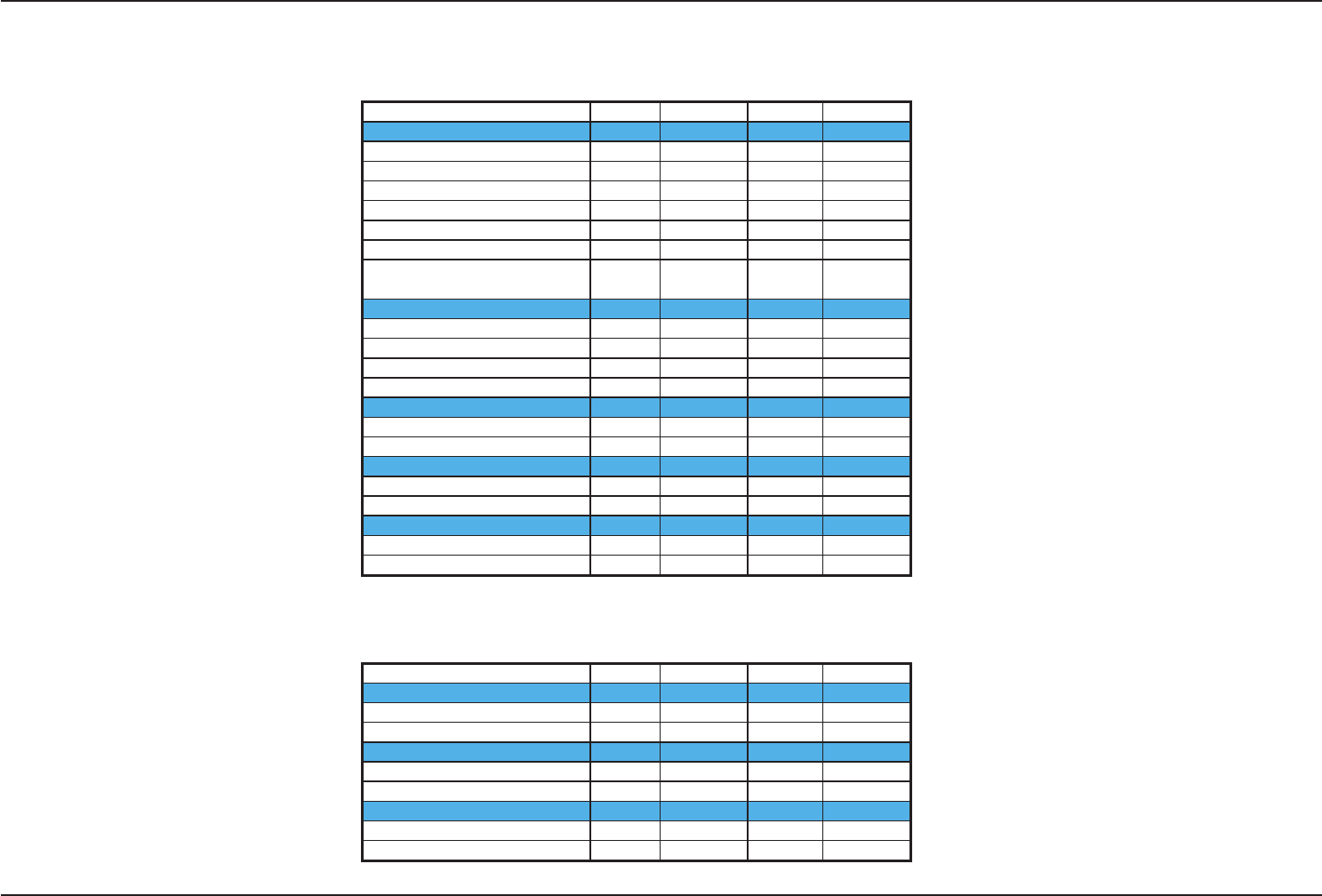
71
07/30/2014
Appendix B. Optical Tip Table
Mentor Visual iQ 6.1mm tips
Part No. Color FOV (deg) DOF mm (in)
Forward View
T6150FF
None 50 50-inf (2.36-inf)
XLG3T6150FG White 50 12-200 (.47-7.87)
XLG3T61120FG Black 120 5-120 (.20-4.72)
XLG3T6180FN Orange 80 3-20 (.12-.79)
XLG3T6190FF Yellow 90 20-inf (.79-inf)
XLG3T6150FB Purple 50(45 DOV) 12-80 (.47-3.15)
T6165FF*
Orange
&Blue
65 65-inf (2.56-inf)
Side View
XLG3T6150SF Brown 50 45-inf (1.77-inf)
XLG3T6150SG Green 50 9-160 (.35-6.30)
XLG3T61120SG Blue 120 4-100 (.16-3.94)
XLG3T6180SN Red 80 1-20 (.04-.79)
3D Phase Measurement
XLG3TM61105FG Black 105 8-250 (.31-9.84)
XLG3TM61105SG Blue 105 7-250 (.27-9.84)
Shadow Measurement
XLG3TM6150FG White 50-FWD 12-30 (.47-1.18)
XLG3TM6150SG Blue 50-SIDE 7-24 (.28-.94)
Stereo Measurement
XLG3TM616060FG Black 60/60-FWD 4-80 (.16-3.15)
XLG3TM615050SG Blue 50/50-SIDE 2-50 (.08-1.97)
* Indicates tip with maximum brightness.
Mentor Visual iQ 4.0mm tips
Part No. Color FOV (deg) DOF mm (in)
Forward View
T4080FF* None 80 35-inf (1.38-inf)
T40115FN Black 115 4-inf (.16-inf)
Side View
T40115SN Red 115 1-30 (.04-1.18)
T40120SF Blue 120 6-inf (.24-inf)
Stereo Measurement
TM405555FG Black 55/55-FWD 5-inf (.20-inf)
TM405555SG Blue 55/55-SIDE 4-inf (.16-inf)
* Indicates tip with maximum brightness.

72 07/30/2014
Appendix C. Chemical Compatibility
Chemical compatibility refers to the probe’s ability to come into contact with various liquid substances and not be damaged.
WARNING Do not use this system in explosive environments.
These substances are safe for a short duration of contact with the insertion tube and tip optics:
• Water
• Aircraft Gasoline
• Jet-A-Fuel
• Isopropyl alcohol
• JP-4 Fuel
• Kerosene
• Synthetic Turbo Oil
• Gasoline
• Diesel Fuel
• Hydraulic Oil
• Inhibited Transformer Oil
Subsequent to contact with the above uids, the insertion tube and tip optics used must be cleaned prior to storage.
Appendix D. Warranty
GE Inspection Technologies warrants its VideoProbe components, when new, to be free from defects in material and workmanship and to perform in accordance with
manufacturer’s specications under normal use and service for a period of one year from the date of purchase from GE Inspection Technologies or its authorized
distributors, except that, the light source is warranted for a period of 3 years from the date of purchase, the battery is warranted for a period of 30 days from the date of
purchase, and where used, servo motors in the articulation drive system are warranted for the life of this VideoProbe product.
GE Inspection Technologies’ obligation under this warranty is limited to the repair or replacement of components determined by GE Inspection Technologies to be
defective within the warranty period at no cost to the original purchaser, except for return shipping expenses. It shall be the purchaser’s responsibility to return the
product to GE Inspection Technologies or one of its authorized service centers. The warranty does not cover accessories or optional equipment not manufactured by
GE Inspection Technologies, but these items may be covered by separate manufacturers’ warranties.
This warranty extends to the original purchaser and cannot be assigned or transferred to any third party. This warranty shall not apply to any damage or product failure
determined by GE Inspection Technologies to have been caused by misuse, accident (including shipping damage), neglect, improper maintenance, modication or
repair by someone other than GE Inspection Technologies or one of its authorized service representatives.
These express warranties are in lieu of any other warranties, express or implied, including the warranties of merchantability and tness for a particular purpose, and no
other person has been authorized to assume for GE Inspection Technologies any other liability in connection with the sale of its VideoProbe products. GE Inspection
Technologies shall not be liable for any loss or damages, whether direct or indirect, incidental, or consequential, resulting from the breach of any express warranty set
forth herein.

73
07/30/2014
Appendix E. Verifying Measurement Tips
Verify measurement tips each time you use them to ensure that no mechanical
damage has degraded their accuracy. Visual iQ systems are shipped with
a measurement verication block. This tool lets you verify the accuracy of
measurement tips. It contains optical measurement targets whose accuracy is
traceable to the United States National Institute of Standards and Technology (NIST)
measurement standards.
These are the part numbers for the verication blocks used with the Visual iQ:
VER2400C For 4.0 mm systems
VER2600D For 6.1 mm systems
To Verify a Stereo or 3DPM Measurement Tip:
Step 1 – A stereo tip must be securely connected and identied (using the Global
Menu). A 3DPM tip need only be securely connected, then select Verify as shown here.
Step 2 – Insert the tip into the appropriate verication block. For 3DPM tips, continue
to follow the on-screen prompts until verication is complete. Note that the results of
this automatic verication are logged in a le for troubleshooting (if required).
Step 3 – For stereo tips, measure the test target that matches the units you use:
inches or mm (click here to learn more about making Stereo Measurements).
Step 4 – Evaluate your results
An experienced user can achieve a measurement of 0.100 ± 0.005 inches (1.00 ± 0.05
mm). If your measurement does not fall within these limits, try the suggestions under
Troubleshooting Measurements.
Each measurement verication block comes with a calibration schedule and a
certicate of calibration (C of C), which notes the calibration date and due date.

74 07/30/2014
Appendix F. Environmental Compliance
The equipment purchased has required the extraction and use of natural resources for its production. It may contain hazardous substances that could impact health and the
environment.
In order to avoid the dissemination of those substances in the environment and to diminish the pressure on the natural resources, we encourage the use of appropriate take-
back systems. Those systems will reuse or recycle most of the materials of end-life equipment in a sound way.
The cross-out wheeled bin symbol encourages the use of those systems.
If more information is needed on the collection, reuse, and recycling systems, please contact the appropriate local or regional waste administration.
EU Battery Directive
This product contains a battery that cannot be disposed of as unsorted municipal waste in the European Union. See the product documentation for specic
battery information. The battery is marked with this symbol, which may include lettering to indicate cadmium (Cd), lead (Pb), or mercury (Hg). For proper
recycling return the battery to your supplier or to a designated collection point.
What do the markings mean?
Batteries and accumulators must be marked (either on the battery or accumulator or on its packaging, depending on size) with the separate collection symbol.
In addition, the marking must include the chemical symbols of specic levels of toxic metals as follows:
Cadmium (Cd) over 0.002%
Lead (Pb) over 0.004%
Mercury (Hg) over 0.0005%
The risks and your role in reducing them
Your participation is an important part of the effort to minimize the impact of batteries and accumulators on the environment and on human health. For proper recycling you
can return this product or the batteries or accumulators it contains to your supplier or to a designated collection point. Some batteries or accumulators contain toxic metals that
pose serious risks to human health and to the environment. When required, the product marking includes chemical symbols that indicate the presence toxic metals: Pb for lead,
Hg for mercury, and Cd for cadmium. Cadmium poisoning can result in cancer of the lungs and prostate gland. Chronic effects include kidney damage, pulmonary emphysema,
and bone diseases such as osteomalcia and osteoporosis. Cadmium may also cause anemia, discoloration of the teeth, and loss of smell (anosmia). Lead is poisonous in all
forms. It accumulates in the body, so each exposure is signi cant. Ingestion and inhalation of lead can cause severe damage to human health. Risks include brain damage,
convulsions, malnutrition, and sterility. Mercury creates hazardous vapors at room temperature. Exposure to high concentrations of mercury vapor can cause a variety of severe
symptoms. Risks include chronic inammation of mouth and gums, personality change, nervousness, fever, and rashes.
Visit www.ge-mcs.com for take-back instructions and more information about this initiative.

75
07/30/2014
Appendix G. Regulatory Compliance
EuropeanCommunity—CENotice:
The mark indicates compliance with the essential requirements of Directive 1999/5/EC. Such marking is indicative that this equipment meets or exceeds the
following technical standards:
EN 300 328
EN 301 893
EN 301 489-1/EN 301 489-17
EN 62311
EuropeanEquipmentClassication
Group 1, Class A
The mark on this product indicates it has been tested to and conforms with the provisions noted within the 2004/108/EC Electromagnetic Compatibility Directive. The
Visual iQ system is in conformance with the following standard: EN61326-1.
Declarations of Conformity are held by GE Inspection Technologies GmbH:
GE Inspection Technologies
GmbH Product Service Center
Lotzenäcker 4
72379 Hechingen Germany
Tel: +49(0) 74719882 0
Fax: +49(0) 74719882 16
Safety Mark
The Visual iQ system is in compliance with the following standards:
UL 61010-1, IEC 61010-1, EN 61010-1 and CSA-C22.2 No. 61010-1.
AdditionalCerticationTesting
MIL-STD-461F: RS103, RE102–Above Deck
MIL-STD-810G: 506.5, 507.5, 509.5, 510.5, 511.5, 514.6, 516.6, 521.3
UN / DOT T1-T8

76 07/30/2014
FCC Compliance Statement:
This device complies with part 15 of the FCC Rules. Operation is subject to the following two conditions:
1) This device may not cause harmful interference and
2) This device must accept any interference received, including interference that may cause undesired operation.
Note: This equipment has been tested and found to comply with the limits for a Class B digital device, pursuant to part 15 of the FCC Rules. These limits are designed to provide
reasonable protection against harmful interferences in a residential installation. This equipment generates, uses and can radiate radio frequency energy and, if not installed
and used in accordance with the instructions, may cause harmful interference to radio communications. However, there is no guarantee that interference will not occur in a
particular installation. If this equipment does cause harmful interference to radio or television reception, which can be determined by turning the equipment off and on, the user
is encouraged to try to correct the interference by one or more of the following measures:
• Reorient or relocate the receiving antenna.
• Increase the separation between the equipment and receiver.
• Connect the equipment into an outlet on a circuit different from that to which the receiver is connected.
• Consult the dealer or an experienced radio/TV technician for help.
FCC Caution:
Any changes or modications not expressly approved by the party responsible for compliance could void the user's authority to operate this equipment.
IMPORTANT NOTE:
FCC Radiation Exposure Statement:
This transmitter must not be co-located or operating in conjunction with any other antenna or transmitter.
Operations in the 5.15-5.25GHz band are restricted to indoor usage only.
Industry Canada Regulatory Statement:
This device complies with Industry Canada license-exempt RSS standard(s). Operation is subject to the following two conditions:
1) This device may not cause interferences, and
2) This device must accept any interferences, including interferences that may cause undesired operation of the device.
Cet appareil est conforme avec Industrie Canada exempts de licence standard RSS (s). L‘utilisation de ce dispositif est autorisée seulement aux conditions suivantes:
1) il ne doit pas produire de brouillage et
2) l’ utilisateur du dispositif doit étre prêt à accepter tout brouillage radioélectrique reçu, même si ce brouillage est susceptible de compromettre le fonctionnement du dispositif.
This equipment complies with FCC radiation exposure limits set forth for an uncontrolled environment.

77
07/30/2014
Complies with the Canadian ICES-003 Class B specications.
Cet appareil numérique de la classe B est conforme à la norme NMB-003 du Canada.
IMPORTANT NOTE:
IC Radiation Exposure Statement:
The transmitter module may not be co-located with any other transmitter or antenna.
Cet équipement est conforme aux limites d’exposition aux rayonnements d’Industrie Canada établies pour un environnement non contrôlé.
Caution:
This device for the band 5150-5250 MHz is only for indoor usage to reduce potential for harmful interference to co-channel mobile satellite systems.
Because high power radars are allocated as primary users (meaning they have priority) in 5250-5350 MHz and 5650-5850 MHz, these radars could cause interference and / or
damage to license exempt LAN devices.
Cet appareil (pour réseaux locaux radioélectriques) dans les bandes de fréquences 5150-5250 MHz est réservé à une utilization à l’intérieur an de réduire le risque d’interférence
avec les systèmes satellites mobiles bicanaux.
Les radars forte puissance sont désignés comme étant les premiers utilisateurs (c’est-à-dire qu’ils ont la priorité) des bandes de fréquences 5250-5350 MHz et 5650-5850 MHz.
Ces stations radarspeuvent provoquer des interférences et/ou des dommages à ce périphérique.
Canadian Notice
This equipment does not exceed the Class A limits for radio noise emissions as described in the Radio Interference Regulations of the Canadian Department of Communications.
Le present appareil numerique n’emet pas de bruits radioelectriques depassant les limites applicables aux appareils numeriques de la classe A prescrites dans le Reglement sur
le brouillage radioelectrique edicte par le ministere des Communications du Canada.
This equipment complies with IC radiation exposure limits set forth for an uncontrolled environment.
78 07/30/2014
Brazil Wireless Statement:
Este equipamento opera em caráter secundário, isto é, não tem direito a proteção contra interferência prejudicial, mesmo de
estações do mesmo tipo, e não pode causar interferência a sistemas operando em caráter primário.
(This equipment operates on a secondary basis, ie, not entitled to protection against harmful interference, even of the same type stations, and cannot cause interference to systems
operating on a primary basis.)
South Korea Wireless Statement:
(EMC registration is done on this equipment for a business use only (Class A). Product seller and user should notice that this equipment is purposed to be used except for house use.)
(This device shall not be used for life-safety related service due to radio interference possibility.)
Taiwan NCC Wireless Statement:
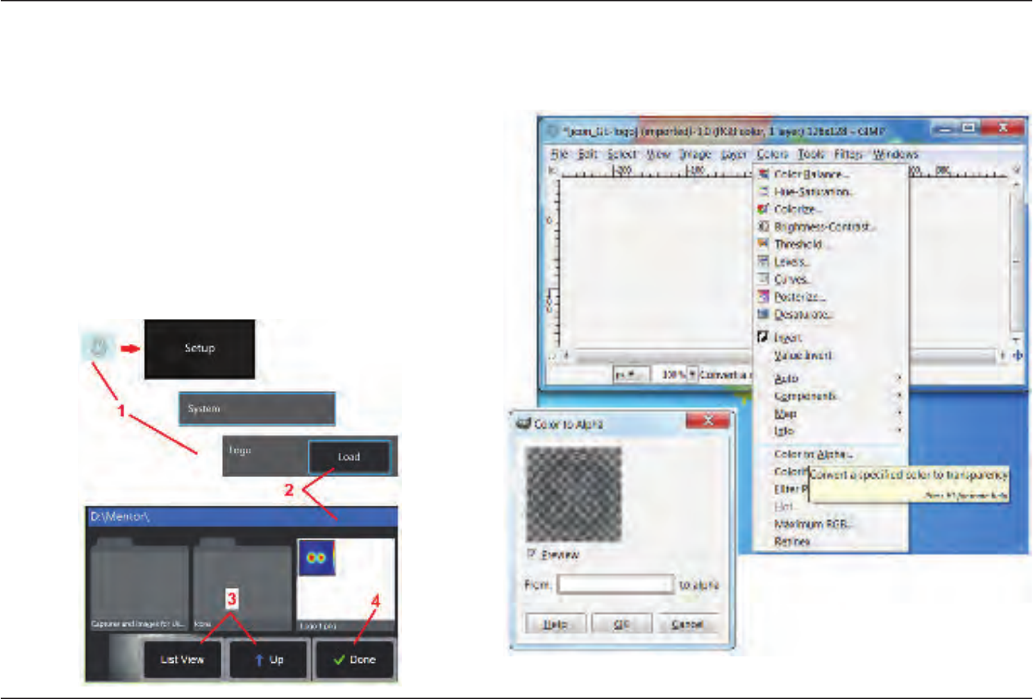
79
07/30/2014
Appendix H. Creating a Personalized Logo File
A custom logo can be loaded into the display, where it will appear in the lower left
corner (in place of the default GE logo). Suitable logos must be saved as PNG le
format and must be no larger than 140 by 140 pixels. It is advisable to use image les
that are approximatley square. To replace the GE icon with a custom icon:
1 – Tap the lower-left corner of the display (typically contains a GE Logo) at any time
to open the Global Menu, select Setup and then open the System menu. You can
now choose to Load a Logo.
2 – Select to Load a Logo. This File Navigation window will open.
3 – Navigate to nd the desired logo le.
4 – Choose the logo le and select Done. The newly loaded logo le appears at the
bottom left of the display screen, provided it is congured to do so by the Screen and
Display Settings.
Note: To incorporate a transparent customized logo, you must first save the
logo le in Photoshop, Gimp 2, or a similar graphics package capable of creating
transparencies. If working in Gimp 2, use these two panels to convert a single-color
image into a transparency.
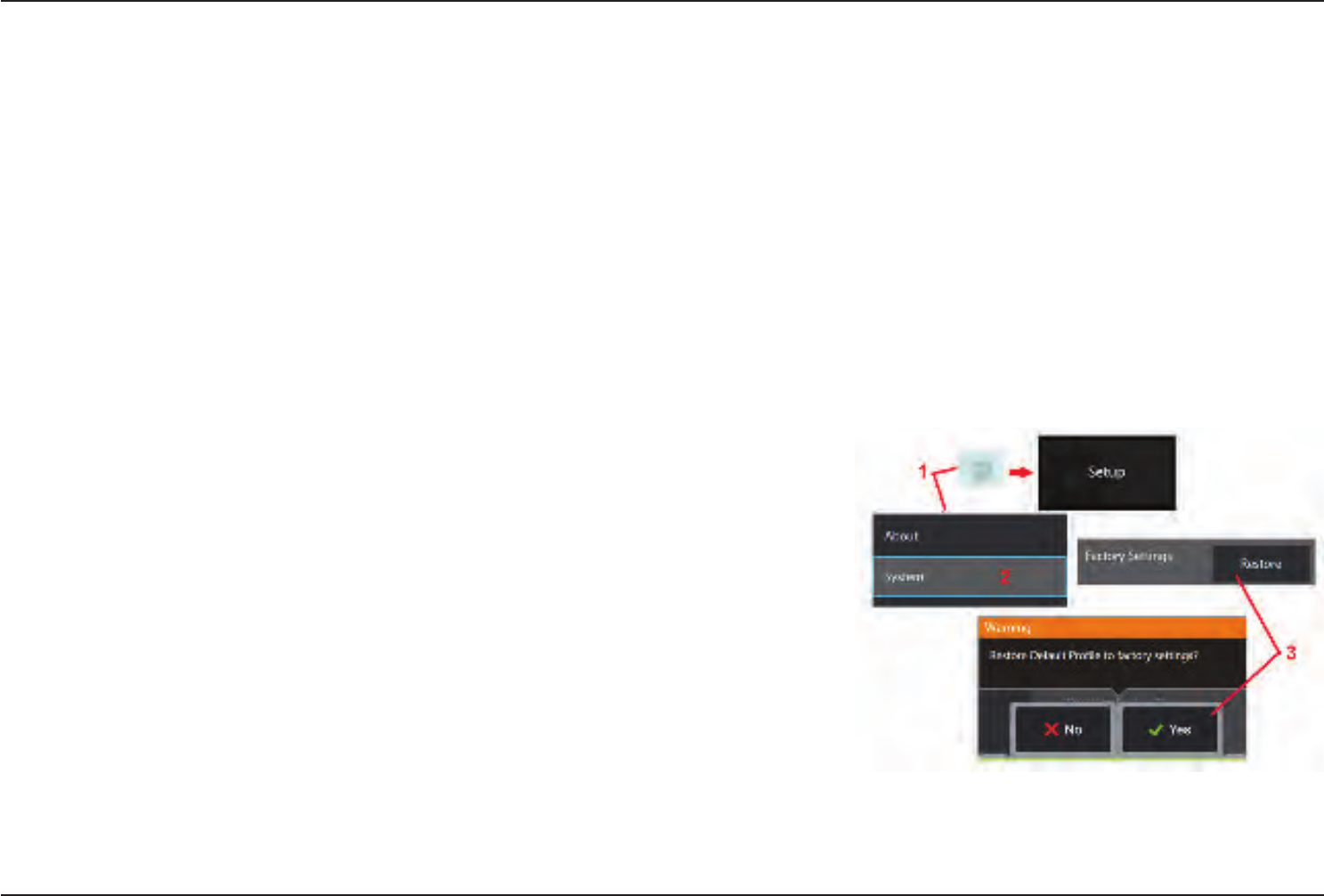
80 07/30/2014
Appendix I. Open Source Software Availability
There are various open source software packages that have been utilized within this product, and to meet license and copyright obligations, a copy of the source code for each
package is available upon request, along with the individual licenses and copyright notices for each, for three years from the date of original installation upon the product.
Requesting these source packages is NOT REQUIRED for operation or use of this product. Additionally, only portions of software on this product fall under open source software
licenses, with the remainder merely being an aggregation on the product’s storage volumes. Thus NO promise is made NOR implied that source code will be provided for the
aggregated proprietary software.
With respect to each open source software distribution, no warrantee is expressed nor implied by either the original authors of the software, nor by any other party involved
in the distribution of the software. More explicit warranty disclaimers are detailed within the license documentation of each software package, again available upon request.
Furthermore such disclaimers and license requirements and restrictions only apply to each open source software package, and DO NOT REFLECT the warranty of the product as
a whole.
There are no additional restrictions placed upon copying, distribution, or modication of each software package beyond those of the original licenses, expressed or implied, due
to their inclusion in this product.
To request a copy of these open source software packages, please have your product model and serial numbers ready, and call customer support representatives at +1 (315)
554-2000, option 3.
Appendix J. Restoring Factory Settings
1 – Tap the on-screen GE Icon at any time to open or close the Global Menu, which provides access to several
features including the Setup Menu.
2 – Tap to open the Setup Menu.
3 – Select Restore, then conrm by selecting Yes to reset all values of the active prole to the factory default
values (Clickheretolearnmoreaboutchangingthecurrentproleorcreatinganewone).
Note: Restoring factory defaults will automatically cause the operating language to revert to English. Click
here to learn how to change the operating language selection.

81
07/30/2014
Symbols
3D Phase Measurement 41
3DPM 41
A
AC-to-DC power adaptor 15
Adaptive Noise Reduction (ANR) 33
Add Audio 37
Annotation 36
ANR 33
Arrows 36
Audio Notes 37
B
Battery Warnings 7
Bluetooth Connections 22
Bluetooth Devices 22
Brightness 32
C
Charging the Battery 14
Chemical Compatibility 65
Cleaning the System 56
Comparison Measurement 52
Component Identication 10
Connectivity 22
Create Folder 55
Customer Support Centers 75
D
Date 19
Date Format 20
Daylight Saving Time 20
Default Prole 18
Depth Prole 43
Distortion Correction 33
Distortion Correction Table 24
E
Editing Files 55
Environmental Compliance 67
F
Factory Default Settings 19
Factory Settings 72
Field of View (FOV) 52
File Manager 30
FOV 52
Freeze 27
G
GE Logo 15
Global Menu 17
I
Image 32
image le type 24
Image Save Location 24
Image Transformation Settings 32
Image & Video 24
Import preset notes 25
Insertion Tube 26
Installing the Battery 14
Inverse+ 33
Invert 32
K
Known Networks 22
L
Large Case 13
Logo 19, 71
Long Exposure 33
M
Magnify 31
Maintenance 56
Mapping the Network Drive 23
Matching Cursors 47
MDI 56
Measurement & Annotation 25
Measurement Tips 40
Measurement Types 40
Index

82 07/30/2014
Measuring 39
Menu Directed Inspections 56
Microphone 24
MTD Number 41
O
Open Source Software 72
Operating Language 10, 20
Optical Tips 16
Optical Tip Table 64
P
Personalized Logo File 71
Play Audio 37
P-Map 25
Point Cloud View 45
Power Management 20
Power Off 15
Power On 15
Preset Annotation 25
Preset Image Transformation Settings 34
Probes 16
Prole 18
Q
Quick Save 29
R
Recalled Image 30
Recalled Video 38
Recording Live Video 38
Reference Dimension 52
Regulatory Compliance 68
Removing the Battery 14
Rename 29
Reset Transforms 33
S
Safety Information 6
Save Options Menu 29
Saving Image Files 29
Screen & Display Setup 21
Setup Menu 17
Single View 33
Small Case 12
Sound Recording 21
Speaker 24
Specications 61
Steer 20
Steer and Stay 20
Steer and Stay mode 26
Steering Mode 26
Steering Sensitivity Settings 20
Stereo Index 25, 46
Stereo Measurements 46
System 19
System Password 19
T
Thumbnail View 55
Time 19
Time Format 20
Time Zone 19
Tip Map 21, 26
Touchscreen 11
touch-sensitive control 21
Troubleshooting Guide 58
Troubleshooting Measurements 53
U
USB Slave Mode 20
V
Verifying Measurement Tips 66
video 38
video recording format 24
Video Save Location 24
View 28
Virtual Keyboard 18
W
Warranty 65
White Balance 19
WiFi 22
Z
Z-Map 25
Zoom 31
Zoom Window 25, 42

83
07/30/2014
Customer Support Centers
North/South America
721 Visions Drive
Skaneateles, NY 13152
Tel: 888-332-3848
315-554-2000 ext. 1
Europe
Robert Bosch Str. 3
50354 Huerth
Germany
Tel: +49 (0) 7471 9882 0
Asia/Pacic
Floor 5, Linkchart Center
2 Tai Yip Street
Kwun tong, Kowloon
Hong Kong
Tel: +852 2877 0801
E-mail: geit-info@ge.com
www.ge-mcs.com
Assembled in USA by GE Inspection Technologies
©2014 General Electric Company.
All rights reserved. Specications subject to change without notice.
©2014 VideoLAN
Printed in USA