GE MDS DS-EL806 EL806 OEM Transnet User Manual 3946A TNET OEM Body
GE MDS LLC EL806 OEM Transnet 3946A TNET OEM Body
UserManual.wiki
>
GE MDS
>
DS-EL806 User Manual
>
users manual
Contents
1.
users manual
2.
Host User Manual
3.
User Manual
users manual
Navigation menu
Upload a User Manual
Namespaces
Wiki Guide
HTML
PDF
Info
Views
User Manual
Discussion / Help
Navigation
![ii TransNET OEM Integration Guide MDS 05-3946A01, Rev. A 5.1 Mounting Dimensions ..................................................... 215.2 Antennas & Feedlines .................................................... 21Feedlines......................................................................... 22 6.0 OPTIMIZING PERFORMANCE............................................. 236.1 Antenna Aiming .............................................................. 236.2 Antenna SWR Check .....................................................236.3 Data Buffer Setting ......................................................... 236.4 Hoptime Setting .............................................................. 236.5 Operation at 115200 bps ................................................ 246.6 Baud Rate Setting .......................................................... 246.7 Radio Interference Checks ............................................. 246.8 RF Output Setting ........................................................... 247.0 OPERATING PRINCIPLES & SPECIAL CONFIGURATIONS ...................................................................... 257.1 How Remotes Acquire Synchronization ......................... 257.2 Establishing a Tail-End Link ............................................ 257.3 Store & Forward (SAF) Operation with Extension Radios 26Simple Extended SAF Network....................................... 26Extended SAF Network................................................... 27Retransmission and ARQ operation................................ 28Synchronization in SAF Networks................................... 28Configuration Parameters for Store-and Forward Services297.4 Sleep Mode Operation (Remote units only) ................... 31Sleep Mode Example...................................................... 32 8.0 DEALING WITH INTERFERENCE........................................ 32 9.0 PROGRAMMING REFERENCE ........................................... 349.1 Programming Methods ................................................... 34Terminal Interface Mode.................................................. 34PC-Based Configuration Software .................................. 349.2 User Commands ............................................................34Entering Commands ....................................................... 359.3 Detailed Command Descriptions .................................... 40ADDR [1–65000] ............................................................. 40AMASK [0000 0000–FFFF FFFF]................................... 41](https://usermanual.wiki/GE-MDS/DS-EL806.users-manual/User-Guide-325986-Page-4.png)
![MDS 05-3946A01, Rev. A TransNET OEM Integration Guide iiiASENSE [HI/LO]..............................................................41BAUD [xxxxx abc] ............................................................41BUFF [ON, OFF]..............................................................41CODE [NONE, 1…255] ...................................................42CTS [0–255].....................................................................42CTSHOLD [0–60000].......................................................43DEVICE [DCE, CTS KEY] ..............................................43DLINK [xxxxx/ON/OFF]....................................................43DKEY...............................................................................44DTYPE [NODE/ROOT] ....................................................44FEC [ON, OFF]................................................................44HOPTIME [7, 28] .............................................................44INIT..................................................................................44HREV...............................................................................45KEY..................................................................................45LEDS [ON, OFF]..............................................................45MODE [M, R, X]...............................................................45OWM [xxxxx]....................................................................45OWN [xxxxx] ....................................................................45PORT [RS232, RS485]....................................................45PWR [20–30] ...................................................................46REPEAT [0–10]................................................................47RETRY [0–10]..................................................................47RSSI ................................................................................47RTU [ON, OFF, 0-80] .......................................................48RX [xxxx]..........................................................................48RXTOT [NONE, 0–1440] .................................................48SAF [ON, OFF] ................................................................48SETUP.............................................................................48SER .................................................................................49SHOW PWR ....................................................................49SHOW SYNC...................................................................49SKIP [NONE, 1...8] ..........................................................49SLEEP [ON, OFF]............................................................50SREV...............................................................................50STAT ................................................................................50TEMP...............................................................................50TX [xxxx]..........................................................................50UNIT [10000–65000] .......................................................50](https://usermanual.wiki/GE-MDS/DS-EL806.users-manual/User-Guide-325986-Page-5.png)
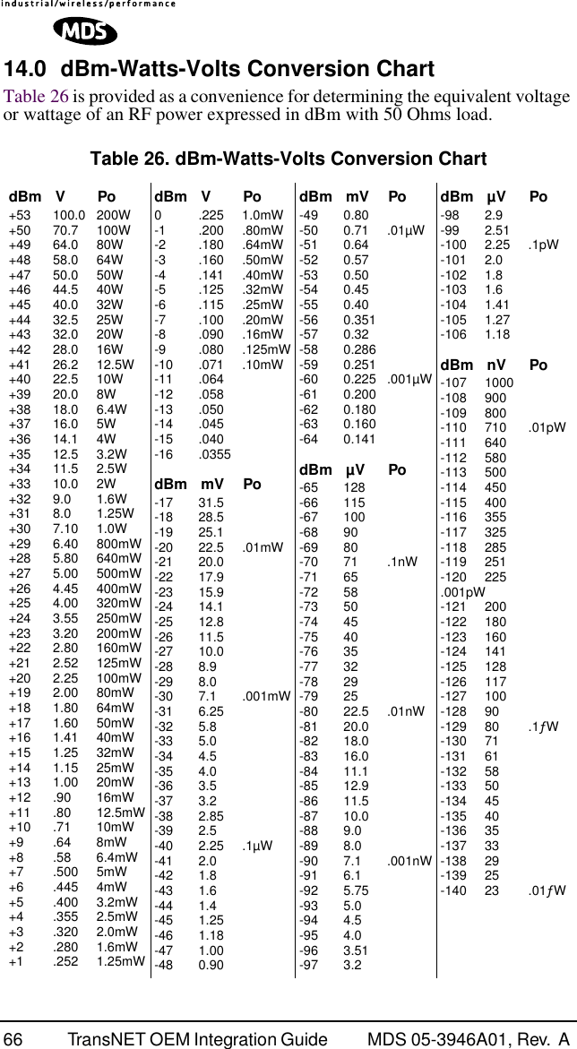
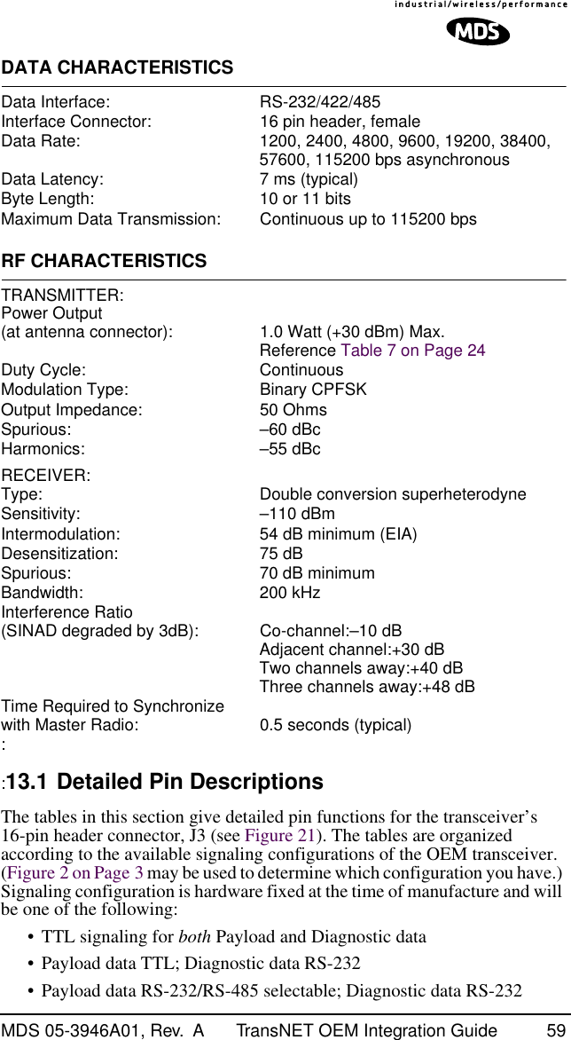
![iv TransNET OEM Integration Guide MDS 05-3946A01, Rev. A XADDR [0–31]................................................................. 51XMAP [00000000-FFFFFFFF] ........................................ 51XPRI [0–31]..................................................................... 51XRSSI [NONE, –40...–120] ............................................. 51ZONE CLEAR ................................................................. 51ZONE DATA..................................................................... 51 10.0 TROUBLESHOOTING......................................................... 5210.1 Alarm Codes ................................................................. 53Checking for Alarms—STAT command ........................... 53Major Alarms vs. Minor Alarms ....................................... 53Alarm Code Definitions ................................................... 5310.2 LED Indicators .............................................................. 5410.3 Troubleshooting Chart ..................................................5410.4 Network-Wide Remote Diagnostics .............................. 55 11.0 FIRMWARE UPGRADES.................................................... 5711.1 Obtaining new firmware ................................................ 57Saving a Web-site firmware file to your PC..................... 5711.2 Installing firmware in your radio .................................... 57 12.0 Security ............................................................................... 57 13.0 Product Specifications......................................................... 5813.1 Detailed Pin Descriptions ............................................. 59 14.0 dBm-Watts-Volts Conversion Chart..................................... 66 To Our Customers We appreciate your patronage. You are our business. We promise to serve and anticipate your needs. We strive to give you solutions that are cost effective, innovative, reliable and of the highest quality possible. We promise to build a relationship that is forthright and ethical, one that builds confidence and trust. Copyright Notice This Installation and Operation Guide and all software described herein are Copyright 2003 by Microwave Data Systems Inc. All rights reserved. Microwave Data Systems Inc. reserves its right to correct any errors and omissions in this manual.](https://usermanual.wiki/GE-MDS/DS-EL806.users-manual/User-Guide-325986-Page-6.png)


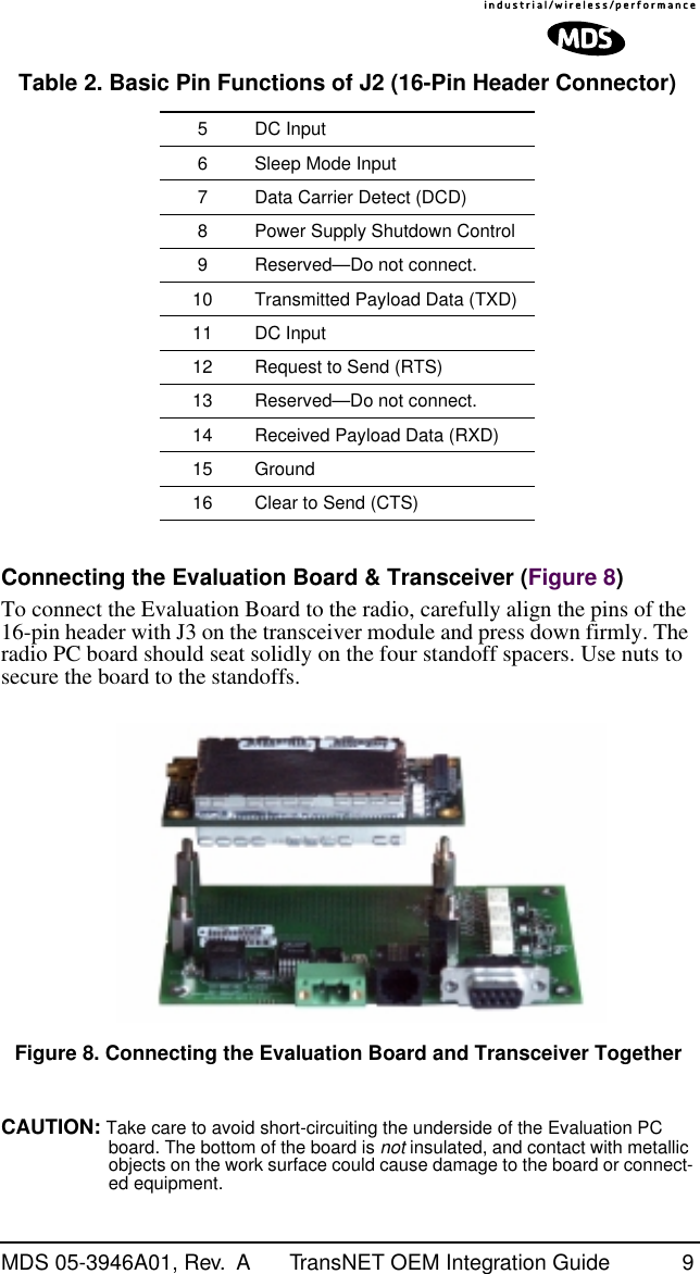
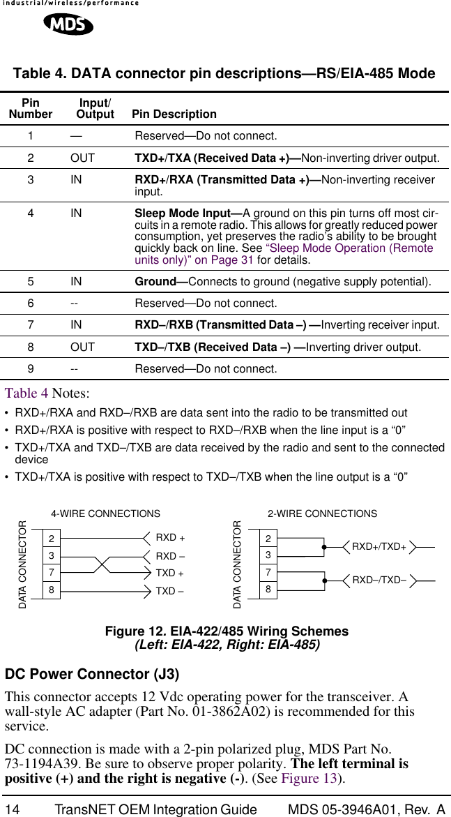
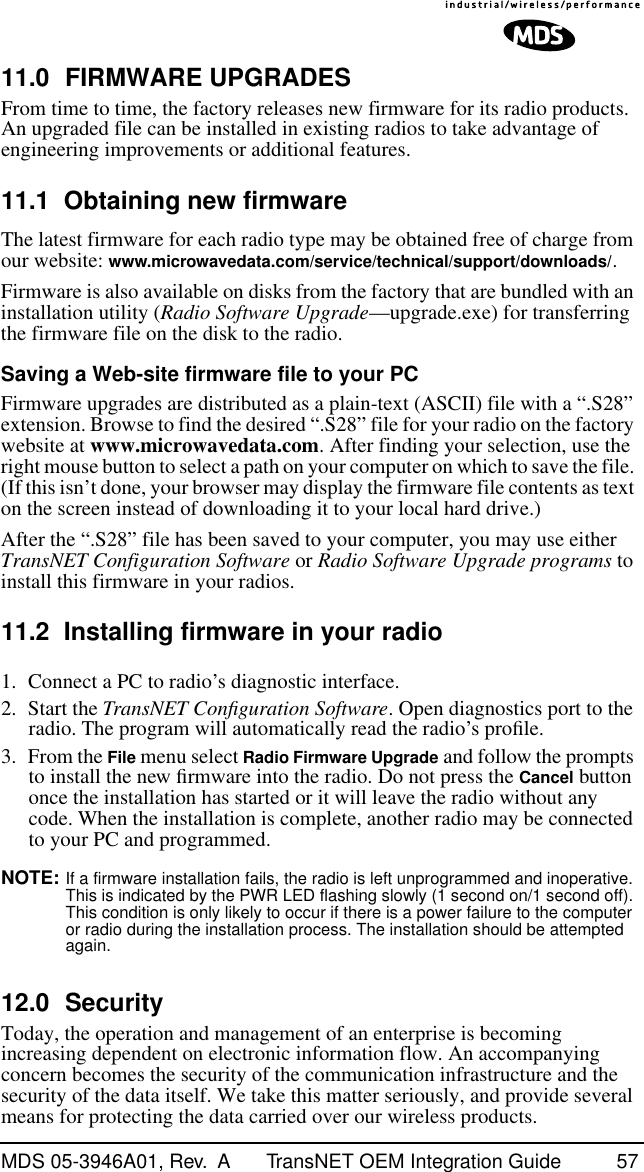
![MDS 05-3946A01, Rev. A TransNET OEM Integration Guide 13 Pin Descriptions—RS/EIA-232 Mode Table 3 lists the DATA connector pin functions for radios configured to operate in RS/EIA-232 mode. Pin Descriptions—RS/EIA-422/485 Mode Table 4 on the following page lists the DATA connector pin functions for radios configured to operate in RS/EIA-422/485 mode. See Figure 12 for wiring schemes. NOTE: Radios equipped with a payload RS-232/485 interface can select PORT RS485 for RS/EIA-485 mode. Table 3. J5 DATA Connector Pinouts—RS/EIA-232 PinNumber Input/Output Pin Description 1 OUT Data Carrier Detect (DCD)— A low indicates hopping syn-chronization has been achieved.2 OUT Received Data (RXD)— Supplies received payload data to the connected device.3IN Transmitted Data (TXD)— Accepts payload data from the connected device.4IN Sleep Mode Input— A ground on this pin turns off most cir-cuits in a remote radio. This allows for greatly reduced pow-er consumption, yet preserves the radio’s ability to be brought quickly back on line. See “Sleep Mode Operation (Remote units only)” on Page 31 for details.5IN Ground— Connects to ground (negative supply potential).6 OUT Alarm condition— A low indicates normal operation. A high indicates an alarm. (See ASENSE [HI/LO] command for more information.)7IN Request to Send (RTS)— A high causes CTS to follow after the programmed CTS delay time has elapsed (DCE).8 OUT Clear to Send (CTS)— Goes high after the programmed CTS delay time has elapsed (DCE), or keys an attached ra-dio when RF data arrives (CTS KEY).9 -- Reserved—Do not connect.](https://usermanual.wiki/GE-MDS/DS-EL806.users-manual/User-Guide-325986-Page-21.png)


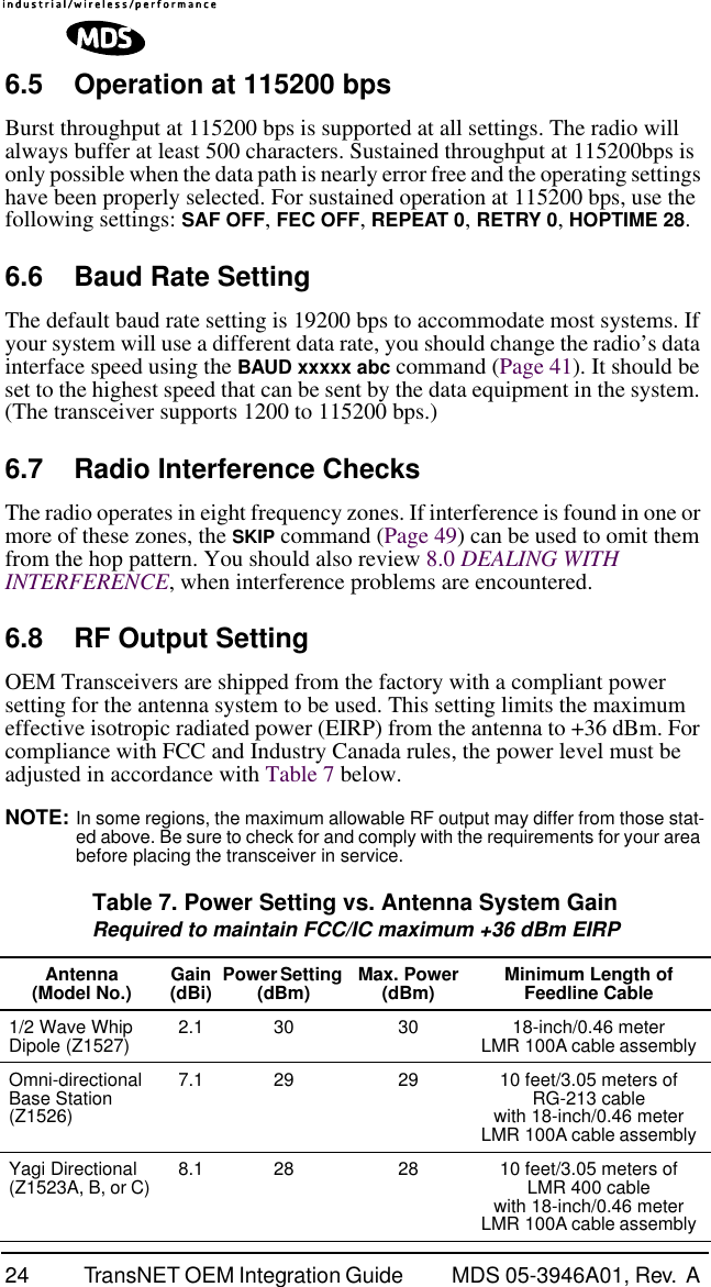
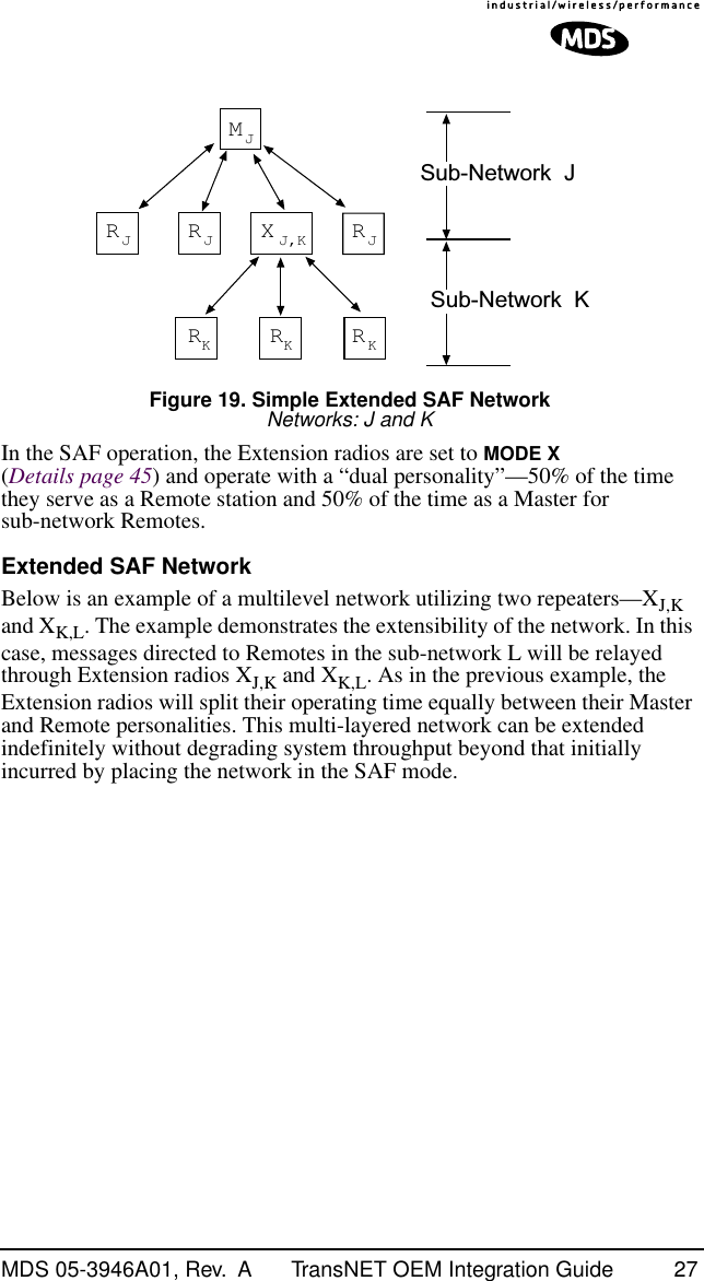
![MDS 05-3946A01, Rev. A TransNET OEM Integration Guide 236.0 OPTIMIZING PERFORMANCEAfter the basic operation of the radio has been checked, you may wish to optimize its performance using some of the suggestions given here. The effectiveness of these techniques will vary with the design of your system and the format of the data being sent.Complete instructions for using the commands referenced in this manual are provided in “PROGRAMMING REFERENCE” on Page 34.6.1 Antenna AimingFor optimum performance of directional antennas (yagis), they must be accurately aimed in the direction of desired transmission. The easiest way to do this is to point the antenna in the approximate direction, then use the remote radio’s RSSI command (Received Signal Strength Indicator) to further refine the heading for maximum received signal strength.In an MAS system, RSSI readings are only meaningful when initiated from a remote station. This is because the master station typically receives signals from several remote sites, and the RSSI would be continually changing as the master receives from each remote in turn.6.2 Antenna SWR CheckIt is necessary to briefly key the transmitter for this check by placing the radio in the SETUP mode (Page 48) and using the KEY command. (To unkey the radio, enter DKEY; to disable the SETUP mode and return the radio to normal operation, enter Q or QUIT.)The SWR of the antenna system should be checked before the radio is put into regular service. For accurate readings, a wattmeter suited for 1000 MHz is required. One unit meeting this criteria is the Bird Model 43 directional wattmeter with a 5J element installed.The reflected power should be less than 10% of the forward power (≈2:1 SWR). Higher readings usually indicate problems with the antenna, feedline or coaxial connectors.6.3 Data Buffer SettingThe default setting for the data buffer is OFF. This allows the radio to operate with the lowest possible latency and improves channel efficiency. MODBUS and its derivatives are the only protocols that should require the buffer to be turned on. See “BUFF [ON, OFF]” on Page 41 for details.6.4 Hoptime SettingThe default hop-time setting is 7 (7 ms). An alternate setting of 28 is used to increase throughput, but at the cost of increased latency. A detailed explanation of the HOPTIME command can be found on Page 44.](https://usermanual.wiki/GE-MDS/DS-EL806.users-manual/User-Guide-325986-Page-31.png)


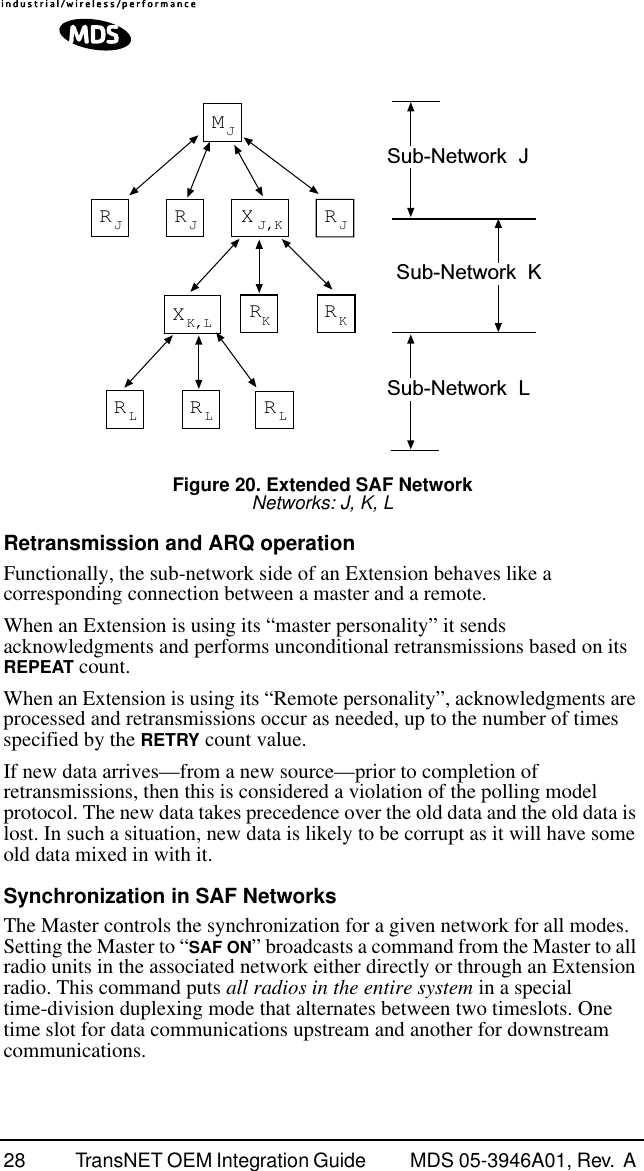

![32 TransNET OEM Integration Guide MDS 05-3946A01, Rev. A It is important to note that power consumption will increase somewhat as communication from the master station degrades. This is because the radio will spend a greater period of time “awake” looking for synchronization messages from the master radio.In order for the radio to be controlled by the Sleep Mode pin, the radio must be set to SLEEP ON. See “SLEEP [ON, OFF]” on Page 50 for more information.Sleep Mode ExampleThe following example describes Sleep Mode implementation in a typical system. Using this information, you should be able to configure a system that meets your own particular needs.Suppose you need communications to each remote site only once per hour. Program the RTU to raise an EIA/RS-232 line once each hour (DTR for example) and wait for a poll and response before lowering it again. Connect this line to Pin 6 of the radio’s header connector. This will allow each RTU to be polled once per hour, with a significant savings in power consumption.8.0 DEALING WITH INTERFERENCEThe transceiver shares the frequency spectrum with other services and other Part 15 (unlicensed) devices in the USA. As such, near 100% error free communications may not be achieved in a given location, and some level of interference should be expected. However, the radio’s flexible design and hopping techniques should allow adequate performance as long as care is taken in choosing a suitable location and in configuring the radio’s operating parameters.In general, keep the following points in mind when setting up your communications network:1. Systems installed in rural areas are least likely to encounter interference; those in suburban and urban environments are more likely to be affected by other devices operating in the license-free frequency band and by adjacent licensed services.2. If possible, use a directional antenna at remote sites. They confine the transmission and reception pattern to a narrow lobe, which minimizes interference to (and from) stations located outside the pattern.3. If interference is suspected from a nearby licensed system (such as a paging transmitter), it may be helpful to use horizontal polarization of all antennas in the network. Because most other services typically use vertical polarization in this band, an additional 20 dB of attenuation to interference can be achieved by using the horizontal plane.4. Multiple spread spectrum systems can co-exist in close proximity to each other with only minor interference, provided they are each assigned a unique network address. Each network address has a different hop pattern associated with it.](https://usermanual.wiki/GE-MDS/DS-EL806.users-manual/User-Guide-325986-Page-40.png)

![MDS 05-3946A01, Rev. A TransNET OEM Integration Guide 35Entering CommandsThe proper procedure for entering commands is to type the command, followed by an keystroke. For programming commands, the command is followed by , the appropriate information or values, and then . Table 11. Network Configuration—Master Station COMMAND DESCRIPTION BUFF [ON, OFF]Details, page 41 ON = Seamless dataOFF = Fast byte throughput.FEC [ON, OFF]Details, page 44 Sets/disables FEC (Forward Error Correction) setting.HOPTIME [7, 28]Details, page 44 Displays hop-time or sets it to 7 or 28 ms.REPEAT [0–10]Details, page 47 Sets/displays the fixed downstream re-send count.RETRY [0–10]Details, page 47 Sets/displays the maximum upstream re-send count for ARQ (Automatic Repeat Request) operationSAF [ON, OFF]Details, page 48 Enables/disables the store-and-forward func-tion for the network controlled by this Master unit.SKIP [NONE, 1...8]Details, page 49 Skip one or more frequency zonesTable 12. Network-Wide Diagnostics Command DescriptionDLINK [xxxxx/ON/OFF]Details, page 43 Controls operation of diagnostic link function.DTYPE [NODE/ROOT]Details, page 44 Set radio’s operational characteristics for net-work-wide diagnosticsENTERSPACEENTER](https://usermanual.wiki/GE-MDS/DS-EL806.users-manual/User-Guide-325986-Page-43.png)
![36 TransNET OEM Integration Guide MDS 05-3946A01, Rev. A Table 13. Operational Configuration—Set/Program Command DescriptionADDR [1–65000]Details, page 40 Program network addressAMASK [0000 0000–FFFF FFFF]Details, page 41 Sets alarm response. Default: FFFF FFFFASENSE [HI/LO]Details, page 41 Sense of the radio’s alarm output in the EIA-232 mode. Default: Alarm present = HI. BAUD [xxxxx abc]Details, page 41 Data communication parametersCODE [NONE, 1…255]Details, page 42 Select the security/encryption setting in the radio.CTS [0–255]Details, page 42 CTS delay in milliseconds.(A value of 0 returns CTS immediately)CTSHOLD [0–60000]Details, page 43 “Hold time” that CTS is present following last character from DATA port.DEVICE [DCE, CTS KEY]Details, page 43 Device behavior: DCE (normal) or CTS KeyLEDS [ON, OFF]Details, page 45 Enables/disables transceiver LEDsMODE [M, R, X]Details, page 45 Operating mode: where M = Master, R = RemoteOWM [xxxxx]Details, page 45 Owner’s message, or alternate message (30 characters maximum)OWN [xxxxx]Details, page 45 Owner’s name, or alternate message(30 characters maximum)PORT [RS232, RS485]Details, page 45 Data port (DATA connector) interface signal-ing mode: RS232 or RS485PWRDetails page 47 Forward power-output setting in dBmREPEAT [0–10]Details, page 47 Forward power output in dBm.RXTOT [NONE, 0–1440]Details, page 48 Maximum duration (in minutes) before time-out alarm. Default is OFF. RTU [ON, OFF, 0-80]Details, page 48 Enable or Disable unit’s built-in RTU simula-tor. Default is OFF. Set RTU address between zero and 80.](https://usermanual.wiki/GE-MDS/DS-EL806.users-manual/User-Guide-325986-Page-44.png)
![MDS 05-3946A01, Rev. A TransNET OEM Integration Guide 37 SLEEP [ON, OFF]Details, page 50 Enable or Disable the radio’s Sleep mode function.UNIT [10000–65000]Details, page 50 Unit address used for network-wide diagnos-tics. (Unique within associated network.)XADDR [0–31]Details, page 51 This unit’s Extended addressTypically, the Master is set to zero (0). XPRI [0–31]Details, page 51 Address of the primary Extended radio unit (Extension).XMAP [00000000-FFFFFFFF]Details, page 51Included Extended units in MODE X. (Exten-sions and Remotes only). XRSSI [NONE, –40...–120]Details, page 51 Minimum RSSI level required to preserve syn-chronization with a non-primary radio. (Only meaningful when XPRI is not NONE)ZONE CLEARDetails, page 51 Reset zone data statisticsTable 14. Operating Status—Display Only Command DescriptionADDRDetails page 40 Network addressAMASKDetails page 41 Alarm mask (response)ASENSEDetails page 41 Current sense of the alarm output.BAUDDetails page 41 Data communication parameters. Example: BAUD 9600 8N1BUFFDetails page 41 Data buffering mode: ON = seamless data, OFF = fast byte throughputCODEDetails page 42 Security/encryption operational status.“NONE” (Inactive), or “ACTIVE”CTSDetails page 42 CTS delay in milliseconds (0–255 ms)CTSHOLDDetails page 43 “Hold time” that CTS is present following last character from DATA port.Table 13. Operational Configuration—Set/Program (Continued)Command Description](https://usermanual.wiki/GE-MDS/DS-EL806.users-manual/User-Guide-325986-Page-45.png)
![38 TransNET OEM Integration Guide MDS 05-3946A01, Rev. A DEVICEDetails page 43 Device behavior Alternatives: DCE and CTS KEYHOPTIMEDetails page 44 Hop-time value in milliseconds (ms).HREVDetails, page 45 Hardware revision levelLEDS [ON, OFF]Details, page 45 Enables/disables transceiver LEDsMODEDetails page 45 Current operating mode: M = MasterR = RemoteX = Extension (Repeater)OWMDetails page 45 Owner’s message or site nameOWNDetails page 45 Owner’s name or system namePORTDetails page 45 Current data port (DATA connector) interface signaling mode: RS232 or RS485PWRDetails page 47 Show forward power-output setting in dBmREPEATDetails page 47 The fixed downstream re-send count.RETRYDetails page 47 The maximum upstream re-send count for ARQ (Automatic Repeat Request) operation.SAFDetails page 48 The store-and-forward function status.SKIPDetails page 49 Table of frequency zones programmed to be skippedRSSIDetails page 47 Received signal strength indicator (dBm). Unavailable at Master unless SETUP is enabled.RXTOTDetails page 48 The amount of time (in seconds) to wait before issuing a time-out alarm. RTUDetails page 48 RTU simulator’s operational status (ON/OFF)Table 14. Operating Status—Display Only (Continued)Command Description](https://usermanual.wiki/GE-MDS/DS-EL806.users-manual/User-Guide-325986-Page-46.png)
![40 TransNET OEM Integration Guide MDS 05-3946A01, Rev. A 9.3 Detailed Command DescriptionsThe essential commands for most applications are Network Address (ADDR), Mode (MODE), and Baud Rate (BAUD). However, proper use of the additional commands allows you to tailor the transceiver for a specific use, or to conduct basic diagnostics on the radio. This section gives more detailed information for the commands listed above in section 9.2.Most of the commands below can be used in two ways. First, you can type only the command name (for example, ADDR) to view the currently programmed data. Second, you can set or change the existing data by typing the command, followed by a space, and then the desired entry (for example, ADDR 1234). In the list below, allowable programming variables, if any, are shown in brackets [ ] following the command name.ADDR [1–65000]This command sets or displays the radio’s network address. The network address can range from 1 to 65000.A network address must be programmed at the time of installation and must be common across each radio in a given network. Radios are typically shipped with the network address unprogrammed, causing the address to display as NONE. If the address is not set (or is set to a wrong value) it leaves the system in an invalid state, preventing operation and generating an alarm.NOTE: It is recommended that the last four digits of the master radio’s serial number be used for the network address. This helps avoid conflicts with other users.TX [xxxx]Details, page 50 Set/display transmit test frequency. (Radio must be in Setup mode.)RX [xxxx]Details, page 48 Set/display receive test frequency. (Radio must be in Setup mode.)SETUPDetails, page 48 Enables Setup mode. Times out after 10 min-utes. Press “Q” to quit.ZONE DATADetails, page 51 Zone data statisticsZONE CLEARDetails, page 51 Clears the Zone Data logTable 15. Diagnostic and Test Functions (Continued)Command Description](https://usermanual.wiki/GE-MDS/DS-EL806.users-manual/User-Guide-325986-Page-48.png)
![MDS 05-3946A01, Rev. A TransNET OEM Integration Guide 41AMASK [0000 0000–FFFF FFFF]This command sets the alarm bits that cause the alarm output signal to be triggered. The PWR LED will still flash for all alarms, but the alarm output signal will only be activated for those alarms that have the corresponding mask bit set. The hex value for the mask aligns directly with the hex value for the ALARM command. The default is FFFF FFFF. Through proper use of the AMASK command, it is possible to tailor the alarm response of the radio. Contact the factory for more information on configuring the alarm mask.ASENSE [HI/LO]This command is used to set the sense of the radio’s alarm output at Pin 3 of the 16-pin header connector. The default setting is HI which means an alarm exists when an RS-232 high is on Pin 3.BAUD [xxxxx abc]This command sets or displays the communication attributes for the normal payload communications through the DATA port. The command has no effect on the RJ-11 DIAG(NOSTICS) port.The first parameter (xxxxx) is baud rate. Baud rate is specified in bits-per-second and must be one of the following speeds: 1200, 2400, 4800, 9600, 19200, 38400, 57600, or 115200. At baud rates of 19200 bps or less, the radio can support unlimited continuous data transmission at any hop rate.The second parameter of the BAUD command (abc) is a 3-character block indicating how the data is encoded. The following is a breakdown of each character’s meaning:a = Data bits (7 or 8)b = Parity (N for None, O for Odd, E for Even)c = Stop bits (1 or 2)The factory default setting is 9600 baud, 8 data bits, no parity, 1 stop bit (Example: 19200 8N1).NOTE: 7N1, 8O2, and 8E2 are invalid communication settings and are not supported by the transceiver.BUFF [ON, OFF]This command sets or displays the received data handling mode of the radio. The command parameter is either ON or OFF. (The default is OFF.) The setting of this parameter affects the timing of received data sent out the DATA connector. Data transmitted over the air by the radio is unaffected by the BUFF setting.If data buffering is set to OFF, the radio will operate with the lowest possible average latency. Data bytes are sent out the DATA port as soon as an incoming RF data frame is processed. Average and typical latency will both be below 10 ms, but idle character gaps may be introduced into the outgoing data flow.](https://usermanual.wiki/GE-MDS/DS-EL806.users-manual/User-Guide-325986-Page-49.png)
![42 TransNET OEM Integration Guide MDS 05-3946A01, Rev. A If data buffering is ON, the radio will operate in a seamless mode. That is, data bytes will be sent over the air as quickly as possible, but the receiver will buffer the data until the entire packet has been collected. The delay introduced by data buffering is variable and depends on message size and the number of retransmissions required, but the radio will not create any gaps in the output data stream. This mode of operation is required for protocols such as MODBUS™ that do not allow gaps in their data transmission.Seamless mode (BUFF ON) is intended only for applications where the message size is 256 characters or less. Enforcement of this rule is left up to the user. If more than 256 characters are transmitted data delivery will not be seamless and data may be lost.Changes to the BUFF setting may only be made at the master radio. This is because the master radio broadcasts the buffer setting for the entire network. At remote radios, the buffer setting may be read when the radio is in synchronization with the master, but it may not be changed.CODE [NONE, 1…255]The CODE command is used to select or display the security/encryption setting in the radio.The default is CODE NONE. Setting CODE to a value other than NONE provides an extra level security beyond that provided by the Network Address (ADDR). The disadvantage is increased complexity in managing the network. The CODE command takes an argument 1…255, or “NONE”. Entering CODE without an argument will display either “NONE” or “ACTIVE”. ACTIVE means that security/encryption has been enabled, but the radio will not display the security argument.When a CODE value is active, all radios in the system must use the same code value. If the code value is not properly programmed, a remote radio will not synchronize with the master.CAUTION: Record the CODE value and store it in a safe place. If the code is later forgotten, and a unit is to be added to the system, all radios in the network must be set to NONE and then reprogrammed to a new value.CTS [0–255]The CTS (clear-to-send) command sets or displays the timer value associated with the CTS line response. The command parameter ranges from 0 to 255 milliseconds.For DCE operation, the timer specifies how long to wait after the RTS line goes high before asserting the CTS line. A timer value of zero means that the CTS line will be asserted immediately following the assertion of RTS.For CTS Key operation (see the DEVICE command), the timer specifies how long to wait after asserting the CTS line before sending data out the DATA port. A timer value of zero means that data will be sent out the data port without imposing a key-up delay. (Other delays may be in effect from other radio operating parameters.)](https://usermanual.wiki/GE-MDS/DS-EL806.users-manual/User-Guide-325986-Page-50.png)
![MDS 05-3946A01, Rev. A TransNET OEM Integration Guide 43CTSHOLD [0–60000]Used in DEVICE CTS KEY mode, this command sets the amount of time in milliseconds that CTS remains present following transmission of the last character out the RXD pin of the DATA port. This “hold time” can be used to prevent squelch tail data corruption when communicating with other radios.The CTSHOLD setting can range from 0 to 60000 (i.e., 60 seconds). The default value is 0, which means that CTS will drop immediately after the last character is transmitted. If the command is entered when the radio is in DEVICE DCE mode, the response CTSHOLD N/A will be displayed.DEVICE [DCE, CTS KEY]The DEVICE command sets or displays the device behavior of the radio. The command parameter is either DCE or CTS KEY.The default selection is DCE. In this mode, CTS will go high following RTS, subject to the CTS programmable delay time. Keying is stimulated by the input of characters at the data port. Hardware flow control is implemented by dropping the CTS line if data arrives faster than it can be transmitted.If CTS KEY is selected, the radio is assumed to be controlling another radio, such as in a repeater or tail-end link system. The RTS line is ignored and the CTS line is used as a keyline control for the other radio. CTS is asserted immediately after the receipt of RF data, but data will not be sent out the DATA port until after the CTS programmable delay time has expired. (This gives the other radio time to key.)Following transmission of the last byte of data, CTS will remain asserted for the duration specified by the CTSHOLD command. CTSHOLD should be set sufficiently high.DLINK [xxxxx/ON/OFF] DLINK ON enables use of Diagnostic Link mode and establishes it as the default protocol on the RJ-11 DIAG port. Diagnostic Link mode is a special protocol used to support Network-Wide Diagnostics. DLINK must be set to ON to support connection to InSite or to support chained diagnostics between radio networks. DLINK OFF disables this feature. The default setting is ON.The following DLINK baud rates selections are allowed:• 1200 • 4800 • 9600 • 19200 (default)• 38400 • 57600 • 115200Example: DLINK 4800 sets the RJ-11 DIAG port to operate at 4800 bps when diagnostics is “closed”. This setting will not affect the port’s autobaud operation. Use only of DLINK ON, will enable the use 19200 or the most recently programmed value. The default is DLINK 19200 and DLINK ON. NOTE: The same baud rate must be entered into the InSite Equipment List’s BAUD field.](https://usermanual.wiki/GE-MDS/DS-EL806.users-manual/User-Guide-325986-Page-51.png)
![44 TransNET OEM Integration Guide MDS 05-3946A01, Rev. A NOTE: The DLINK rate must match the rate of any connected device to the diagnostic port. This may be either another radio’s diagnostic port, the InSite computer, or another data link device that eventually connects to the InSite computer.DKEYDisables the transmitter when it is keyed. See also KEY command.DTYPE [NODE/ROOT]The DTYPE command specifies the radio’s operational characteristics for network-wide diagnostics. The transceiver uses the following types:•NODE–The most common setting, and the default. This is the basic system radio device-type. Typically, the radio network is comprised of nodes and one root. Intrusive diagnostics can originate from any node. However, non-intrusive diagnostics can only be conducted from the root node.•ROOT–Always one, and only one, per network (including units associated through Extension units.) The root is the focal point of network-wide diagnostics information. Intrusive diagnostics can originate from any radio, including the root. However, the root is the only radio through which non-intrusive diagnostics can be conducted.FEC [ON, OFF]This command is used to view the FEC setting, or turn it on or off. The default setting is FEC ON. (It needs to be turned off when throughputs exceed 57,600 bps.) FEC is set at the master and is automatically passed on to all of the remotes in a network.Setting FEC to ON improves sensitivity at the cost of reduced throughput. Typical SCADA/telemetry applications use low data rates and, as such, the FEC setting is normally transparent to them.HOPTIME [7, 28]The HOPTIME command is used to set or display the hop-time setting. The command is a digit corresponding to the hop-time setting in milliseconds. The default HOPTIME setting is 7. A setting of 28 must be used when throughputs exceed 57,600 bps.Changes to the HOPTIME setting may only be made at the master radio. (This is because the Master radio establishes the hop-time setting for the entire network.) At remote radios, the hop-time setting may be read when the radio is in synchronization with the master, but it may not be changed.INITThe INIT command is used to reset the radio’s operating parameters to the factory defaults listed in Table 16 on Page 46. This may be helpful when trying to resolve configuration problems that resulted from the entry of one or more improper command settings. If you are unsure of which command setting caused the problem, this command allows you to get back to a known working state.](https://usermanual.wiki/GE-MDS/DS-EL806.users-manual/User-Guide-325986-Page-52.png)
![MDS 05-3946A01, Rev. A TransNET OEM Integration Guide 45NOTE: Caution should be exercised when using the INIT command on radios in a sys-tem employing the Store-and-Forward feature. Settings relating to the use of Extension services will be lost and will need to be re-entered. Inventory and record the settings for XADDR, XPRI and XMAP before using the INIT com-mand.SPECIAL NOTE: Installing firmware of Revision 2.0 or later into a radio with Revi-sions 1.x firmware will preserve the radio’s compatibility with other radios run-ning Revision 1.x firmware. If updating the radio’s firmware is part of a system-wide upgrade, the last step should be to use the INIT command at the Master station. Use of the INIT command causes the changes shown in Table 16 on Page 46 to be appliedHREVShows the Hardware revision of the radio.KEYEnables the transmitter. (Radio must be in Setup mode.) See also DKEY command.LEDS [ON, OFF]This command is used to view the LED setting, or to enable/disable LED operation. In power-critical applications (battery/solar powered sites, for example), it may be desirable to turn off the LEDs.MODE [M, R, X]The MODE command sets or displays the operating mode of the radio. A master radio is set by MODE M; a remote set by MODE R, and an Extension is set by MODE X.All units default to remotes; other modes must be specifically programmed with the MODE command.If MODE X is used, the MODE X radio should be programmed with an Extended Address (XADDR). Units that need to hear this MODE X radio must be programmed with an appropriate XPRI and/or XMAP value.OWM [xxxxx]The OWM command sets or displays an optional owner’s message, such as the system name. The entry can contain up to 30 characters.OWN [xxxxx]The OWN command sets or displays an optional owner’s name, such as the site name. The entry can contain up to 30 characters.PORT [RS232, RS485]Select or identify the current data interface signaling mode: RS232 or RS485. This is the port though which the payload data will pass. Pin descriptions for EIA-232 are on Page13 and EIA-485 can be found on Page13. Note: This command will always show TTL if the radio is only equipped for TTL service—see model number configuration code on Page 3.](https://usermanual.wiki/GE-MDS/DS-EL806.users-manual/User-Guide-325986-Page-53.png)
![46 TransNET OEM Integration Guide MDS 05-3946A01, Rev. A PWR [20–30]This command displays or sets the desired RF forward output power setting of the radio. The PWR command parameter is specified in dBm and can range from 20 dBm through 30 in 1 dBm steps. The default setting is 30 dBm (1 watt). To read the actual (measured) power output of the radio, use the SHOW PWR command.In the USA, maximum allowable power is governed by FCC limits on Effective Isotropic Radiated Power output (EIRP). The EIRP limit of +36 dBm means that any user with a net antenna gain greater than 6 dBi must decrease the PWR setting accordingly.Table 16. INIT Command Generated Defaults Parameter Default Setting Corresponding CommandFor all radiosDevice operation DCE DEVICE DCECTS delay 0 (CTS is continuously asserted) CTS 0CTS hold-time 0CTSHOLD 0DATA Interface port • 9600 baud• 8 data bits• none (no parity)• 1 stop bitBAUD 9600 8N1Alarm Mask FFFF FFFF AMASKAlarm Output Sense RS-232 High (+5.0 Vdc) ASENSERX Time-out-Timer None/Disable RXTOTTransmittertest frequency 915.000 MHz TX xxxReceivertest frequency 915.000 MHz RX xxxSleep Enable OFF SLEEP OFFData Port Setting RS/EIA-232 PORT RS232Primary Extension Radio Address 0 (Master) XPRI 0Synchronization Source Map None XMAP 0Extended Address 0XADDR 0For MASTER radiosSkipped frequencies None (radio will hop across all frequencies) SKIP NONEHop-time 7 ms HOPTIME 7Buffer mode OFF BUFF OFF](https://usermanual.wiki/GE-MDS/DS-EL806.users-manual/User-Guide-325986-Page-54.png)
![MDS 05-3946A01, Rev. A TransNET OEM Integration Guide 47REPEAT [0–10]The REPEAT command affects “downstream” data. The command causes a Master or Extension to always repeat transmissions for the specified number of times (range is 0 to 10; default selection is 3). Unlike the RETRY command, there is no acknowledgment that a message has been received. To display the current setting, use the REPEAT command without entering a value.RETRY [0–10]The RETRY command affects upstream data. The command selects, or displays, the maximum number of times (0 to 10) that a remote radio will re-transmit data. The default setting is 10.This command is associated with ARQ (Automatic Repeat Request) operation of the radio and is intended for use in areas with heavy radio interference.When the RETRY command is issued without parameters, the maximum retransmission count is shown. A value of 0 represents no retries, while values of 1 or greater successively improve the chance of data delivery in spectrally harsh environments (at the expense of possibly increased latency). The RETRY value is only settable at the Master. It is readable by a synchronized Remote.RSSIThis command displays the radio’s Received Signal Strength Indication in dBm (decibels relative to 1 mW). The output can range from –40 dBm to –120 dBm. Command availability and results depend on the mode of operation (master or remote). The closer to 0 dBm, the stronger the signal, thus a reading of –70 dBm is stronger than –80 dBm.For a remote radio, under normal operation, RSSI is based on the average signal strength of the SYNC message received in each of the eight frequency zones. (RSSI is sampled each time a SYNC message is received.) When using the RSSI reading to align a directional antenna, it is important to make changes slowly so that the RSSI reading will provide meaningful results. It will take several seconds to indicate a change in signal level. The radio stays in RSSI mode until is pressed.Retry Count 10 (max. 10 repeats for ARQ) RETRY 10Repeat Count 3 (downstream repeats) REPEAT 3Forward Error Correction ON FEC ONTable 16. INIT Command Generated Defaults (Continued) Parameter Default Setting Corresponding CommandENTER](https://usermanual.wiki/GE-MDS/DS-EL806.users-manual/User-Guide-325986-Page-55.png)
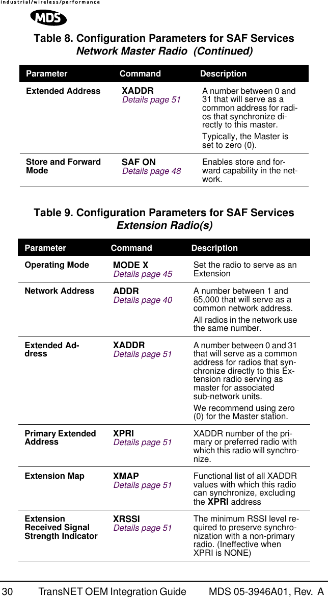
![48 TransNET OEM Integration Guide MDS 05-3946A01, Rev. A For a master radio, under normal operation, entering the RSSI command causes the response NOT AVAILABLE to be returned. This is because a master is normally receiving signals from several remote stations and an RSSI reading would be continually changing. The only exception is when the SETUP command has been asserted. This disables hopping and allows reading a “raw” RSSI signal level in real time from a master or remote radio.NOTE: RSSI readings will not indicate signals stronger than –40 dBm.RTU [ON, OFF, 0-80]This command re-enables or disables the radio’s internal RTU simulator, which runs with proprietary polling programs such as poll.exe and rsim.exe. The internal RTU simulator is available whenever a radio has diagnostics enabled. This command also sets the RTU address that the radio will respond to.The internal RTU can be used for testing system payload data or pseudo bit error rate (BER) testing. It can be helpful in isolating a problem to either the external RTU or the radio. The default RTU setting is OFF.RX [xxxx]This command sets or displays the test receive frequency used in place of hopping when the radio is in SETUP mode. The test receive frequency can be reprogrammed to any value between 902.200 MHz and 927.800 MHz, inclusive. The factory default setting is 915.000 MHz.RXTOT [NONE, 0–1440]This command sets or displays the amount of time (in minutes) to wait for the next received data packet before issuing a receiver time-out alarm. The default setting is NONE.SAF [ON, OFF]This command enables/disables the operation of the Store-and-Forward services. It can be set only at the network’s Master station, but will effect all radios in the associated network. The default setting is OFF. See related commands: “XADDR [0–31]” on Page 51, “XPRI [0–31]” on Page 51, and “XMAP [00000000-FFFFFFFF]” on Page 51.SETUPThis command sets up the transceiver for checking antenna SWR or trans-mitter power with external measuring equipment. Do not use this mode during normal operation.When the SETUP command is entered, the prompt changes to SETUP>, and:• Hopping is disabled.• Synthesizer frequencies are reset to the test frequencies specified by the TX and RX commands described earlier.](https://usermanual.wiki/GE-MDS/DS-EL806.users-manual/User-Guide-325986-Page-56.png)
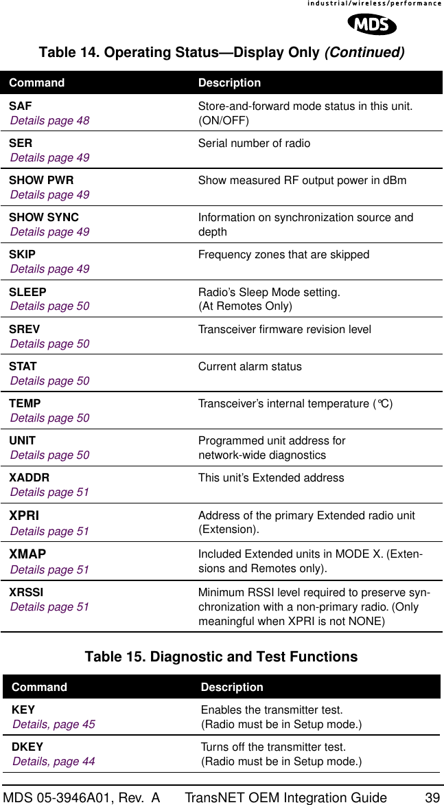
![MDS 05-3946A01, Rev. A TransNET OEM Integration Guide 49• The radio can be keyed using the KEY command. DKEY is used to unkey the radio. (If the radio is left in a keyed state it is automatically unkeyed after several minutes.)• The RSSI is sampled in a raw, continuous fashion regardless of whether the unit is a master or a remote.Entering Q or QUIT returns the system to normal operation.A timer keeps the Setup mode from accidentally leaving the system disabled. After 10 minutes the system behaves as if Q or QUIT had been entered, returning to normal operation.SERDisplays the Serial Number of the radio.SHOW PWR The SHOW PWR command displays the actual (measured) RF power output in dBm. Unlike the PWR command, this command shows the actual level being measured, not the programmed RF power setting.SHOW SYNC When used at a Remote station, this command will display Extended Address and Unit Address of the Master or Extension radio to which the Remote is synchronized. The network depth at the remote, defined as the number of downstream links from the Master, is displayed in parentheses.SKIP [NONE, 1...8]This command sets or displays which, if any, of the eight 3.2 MHz-wide zones will be skipped from the radio’s hopping sequence. Skipping zones is one way of dealing with constant interference on one or more frequencies. See “DEALING WITH INTERFERENCE” on Page 32 for more information on dealing with interference.Table 17 shows the frequency range covered by each zone. The command parameter is either the keyword NONE or an undelimited string of up to four digits where each digit 1...8 represents a corresponding zone to skip. (For zone parameter input, the digits can appear in any order and can be optionally separated by a blank space.) The SKIP command is display-only at remote radios. (Remotes must be synchronized with the master radio to display the skip status.)In the USA, a maximum of four zones may be skipped, per FCC rules. Check the regulatory requirements for your region.Table 17. Frequency ZonesZONE 1 ZONE 2 ZONE 3 ZONE 4 ZONE 5 ZONE 6 ZONE 7 ZONE 8902.200to905.200905.400to908.400908.600to911.600911.800to914.800915.000to918.000918.200to921.200921.400to924.400924.600to927.600](https://usermanual.wiki/GE-MDS/DS-EL806.users-manual/User-Guide-325986-Page-57.png)
![50 TransNET OEM Integration Guide MDS 05-3946A01, Rev. A SLEEP [ON, OFF]This command is used to set or display the radio’s Sleep Mode setting. The default setting is SLEEP OFF. When this mode is enabled (ON), a ground or logic low on Pin 6 of the 16-pin header connector (J3) suspends all normal radio functions, and power consumption is reduced to approximately 8 mA. The radio remains in this state until the low is removed. This function cannot be turned on for a Master or Extension radio.SREVThis command displays the version of the firmware currently loaded into the transceiver.A display of 06-4040A01, 2.0.0 is an example of the firmware version identifier—part number followed by release/version number.STATThis command is used to check the alarm status of the radio. If no alarms exist, the message NO ALARMS PRESENT is returned.If an alarm does exist, a two-digit alarm code (00–31) is displayed and the event is identified as a “Major” or “Minor” alarm. A brief description of the event is also given.If more than one alarm exists, the word MORE appears, and additional alarms may be viewed by pressing the key. Detailed descriptions of the alarm codes are provided in Table 18 on Page 53.TEMPThis command displays the internal temperature of the transceiver in degrees Celsius. (Note that the radio is specified to operate in an environment between –30 C° and +60 C°). This internal reading may be higher than the outside temperature by several degrees.TX [xxxx]This command sets or displays the test transmit frequency used in place of hopping whenever the radio is in Setup mode. The test transmit frequency can be reprogrammed to any value between 902.200 MHz and 927.800 MHz, inclusive. The factory default setting is 915.000 MHz.UNIT [10000–65000]This command sets the unit addressing for network-wide diagnostics. The unit address is factory programmed to the last four digits of the serial number. If re-programmed in the field, the entry must consist of five digits between 10000 and 65000.ENTER](https://usermanual.wiki/GE-MDS/DS-EL806.users-manual/User-Guide-325986-Page-58.png)
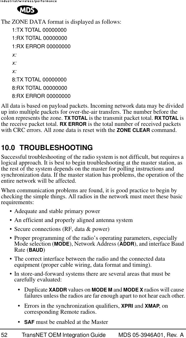
![MDS 05-3946A01, Rev. A TransNET OEM Integration Guide 51XADDR [0–31]Display or program the Extended Address of this radio that will serve as a common address for the sub-network synchronized to this Master or Extension. This value can be listed in the XPRI parameter of associated Extension or Remote radios to allow them to synchronize to this radio. We recommend setting the Master to zero (0). It is easy to remember, and is the default address when the INIT command is used. (Programmed only in Master and Extension radios.)XMAP [00000000-FFFFFFFF]XMAP is a 32-bit hex entry where the least significant bit represents XADDR 0 and the most significant bit represents XADDR 31. The full 32-bit hex value represents the entire list of extensions with which the radio will be allowed to communicate. (Remotes and Extensions only.)This parameter is easily programmed through the TransNET Configuration Software’s Store and Forward Settings panel.XPRI [0–31]Display or program the extended address of a primary radio with which this radio will attempt to synchronize and communicate. A setting of NONE will allow the unit to synchronize with any Master or Extension in the XMAP list. (Parameter only meaningful for a Remote or Extension.)XRSSI [NONE, –40...–120]The XRSSI command is used to set the RSSI minimum signal level required to preserve synchronization with a non-primary Extension radio. This parameter will be ignored if XPRI is set to NONE.ZONE CLEARThe ZONE CLEAR command clears the zone data for all zones in the Zone Data Log, resetting the count to 0. (Zone data is also cleared automatically upon reboot.)ZONE DATAThe transceiver divides its frequency operating spectrum into eight 3.2 MHz-wide zones. (These are the same zones referenced by the SKIP command described earlier.) Data frame statistics are maintained for each zone to indicate the transmission quality of data through the network. This information is useful for identifying zones where significant interference exists.Zone quality information can be accessed using the ZONE DATA command. For each zone (1–8), it shows you the number of data frames sent, the number received, and the number received with errors. If an excessive number of errors are seen in one or more frequency zones, it may indicate interference, and you should consider “skipping” those zones using the SKIP command.Note: If a frequency zone has been skipped, all counts for that zone will be zeros.](https://usermanual.wiki/GE-MDS/DS-EL806.users-manual/User-Guide-325986-Page-59.png)
![56 TransNET OEM Integration Guide MDS 05-3946A01, Rev. A NOTE: The diagnostics feature may not be available in all radios. The ability to query and configure a radio via Network-wide Diagnostics is based on the feature op-tions purchased in the radio being polled.If a PC is connected to any radio in the network, intrusive polling (polling which briefly interrupts payload data transmission) can be performed. To perform diagnostics without interrupting payload data transmission, connect the PC to a radio defined as the “root” radio. A radio is defined as a root radio using the DTYPE ROOT command locally, at the radio.A complete explanation of remote diagnostics can be found in the Network-Wide Diagnostics System Handbook (Part No. 05-3467A01).1. Program one radio in the network as the root radio by entering the DTYPE ROOT command at the radio.2. At the root radio, use the DLINK ON and DLINK [baud rate] commands to configure the diagnostic link protocol on the RJ-11 port.3. Program all other radios in the network as nodes by entering the DTYPE NODE command at each radio.4. Use the DLINK ON and DLINK [baud rate] commands to configure the diagnostic link protocol on the RJ-11 port of each node radio.5. Connect a PC on which InSite software is installed to the root radio, or to one of the nodes, at the radio’s diagnostics port.To connect a PC to the radio’s DIAG port, an RJ-11 to DB-9 adapter (Part No. 03-3246A01) is required. If desired, an adapter cable may be constructed from scratch, using the information shown in Figure 10 on Page 11.6. Launch the InSite program at the PC. (Refer to the InSite user’s manual for details.)Table 21. Network-Wide Diagnostics CommandsCommand DescriptionDLINK [xxxxx/ON/OFF]Details, page 43 Set baud rate of diagnostics linkDTYPE [NODE/ROOT]Details, page 44 Set radio’s operational characteristics for net-work-wide diagnostics](https://usermanual.wiki/GE-MDS/DS-EL806.users-manual/User-Guide-325986-Page-64.png)
![58 TransNET OEM Integration Guide MDS 05-3946A01, Rev. A Our radios address this issue primarily through the use of the following items: 1) A proprietary modem/data link layer—Data signals are processed using code and hardware specifically designed by the manufacturer.2) A unique Network Address—This provides a unique identifier for each radio in a network. A radio is not addressable unless this unique code is included in the data string.3) An optional encryption value (code)—Setting an encryption code requires the use of the CODE command. This command scrambles the radio’s hop pattern and encrypts payload data content. A radio requires the correct Network Address (ADDR) and CODE value in order to synchronize. When the CODE command is used, the same value must be programmed into all radios in the network. See “CODE [NONE, 1…255]” on Page 42 for more details.The effective combination of CODE and ADDR discourage the use of an exhaustive search to gain access to a system. The items described above provide sufficient security for most systems. For highly-sensitive applications, system designers should consider employing application level encryption into their polling protocols to further protect their systems. Third party software tools are available for adding encryption, and these should be considered as part of any advanced encryption scheme.13.0 Product SpecificationsGENERALFrequency Hopping Range: Up to 128 frequencies within 902–928 MHz,configurable in 3.2 MHz zonesHop Pattern: Based on network addressFrequency Stability: ±1.5 ppmHalf-Duplex Operation: ±1.6 MHz TX/RX splitNetwork Addresses: 65,000Temperature Range: –40° C to +70° CHumidity: <95% at +40° C; non-condensingPrimary Power: 13.8 Vdc (6–30 Vdc range)Current Draw (typical):Transmit: 510 mA @ 13.8 VdcReceive: 115 mA @ 13.8 VdcSleep Mode: 8 mA @ 13.8 VdcPhysical Dimensions: 1.81"W x 3.45"L x 0.63"H(46 x 87.5 x 16 mm)Agency Approvals: • FCC Part 15.247 (E5MDS-EL806)• FCC Modular Approval• Industry Canada RSS-210 and RSS-139 (CAN 3738A-MDSEL806)](https://usermanual.wiki/GE-MDS/DS-EL806.users-manual/User-Guide-325986-Page-66.png)
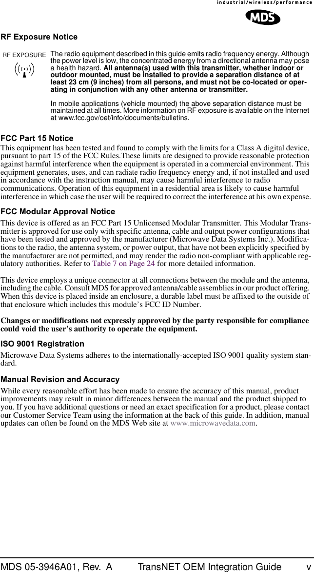
![60 TransNET OEM Integration Guide MDS 05-3946A01, Rev. A Figure 21. 16-pin Header Connector (J3) on OEM Transceiver Board(See parts list (Page18) for information on matching connector)Table 22. Transceiver Connector J3 Pinouts(Payload data TTL; Diagnostic data TTL) Pin No. Input/Output SignalType Name/Description1IN --Ground—Connects to ground (negative supply potential).2 OUT TTL, 3 Vdc Diagnostic TXD—Supplies received diagnos-tic/administrative data to the connected device.3 OUT TTL, 3 Vdc Alarm condition—A low indicates normal opera-tion. A high indicates an alarm. (See ASENSE [HI/LO] command for more information.)4 IN TTL, 3 Vdc Diagnostic RXD—Accepts diagnostic/adminis-trative data from the connected device.5 IN -- FCC 5-25 Vdc version: DC Input (5-25 Vdc)— Supply Source must be capable of furnishing at least 7.5 watts.Non-FCC 3 Vdc version: Do not connect6 IN TTL, 3 Vdc Sleep Mode Input—A ground on this pin turns off most circuits in a remote radio. This allows for greatly reduced power consumption, yet pre-serves the radio’s ability to be brought quickly back on line. See “Sleep Mode Operation (Re-mote units only)” on Page 31 for details.7 OUT TTL, 3 Vdc Data Carrier Detect (DCD)—A low indicates hop-ping synchronization has been achieved.8 IN TTL, 3 Vdc Power Supply Shutdown Control—A ground on this pin causes the OEM module’s power supply to shut down.9 -- -- Non-FCC 3 Vdc version: DC Input (Regulated 3.3 Vdc)—Supply Source must be capable of fur-nishing at least 7.5 watts.FCC 5-25 Vdc version: Do not connect116253487691514 1312 1110](https://usermanual.wiki/GE-MDS/DS-EL806.users-manual/User-Guide-325986-Page-68.png)
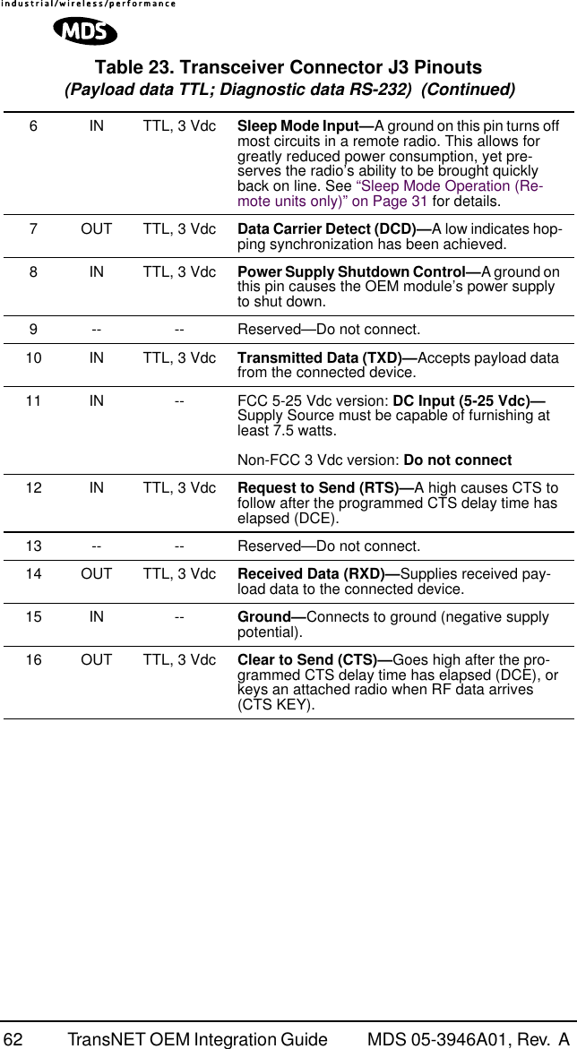
![MDS 05-3946A01, Rev. A TransNET OEM Integration Guide 6110 IN TTL, 3 Vdc Transmitted Data (TXD)—Accepts payload data from the connected device.11 IN -- FCC 5-25 Vdc version: DC Input (5-25 Vdc)— Supply Source must be capable of furnishing at least 7.5 watts.Non-FCC 3 Vdc version: Do not connect12 IN TTL, 3 Vdc Request to Send (RTS)—A high causes CTS to follow after the programmed CTS delay time has elapsed (DCE).13 -- -- Reserved—Do not connect.14 OUT TTL, 3 Vdc Received Data (RXD)—Supplies received pay-load data to the connected device.15 IN -- Ground—Connects to ground (negative supply potential).16 OUT TTL, 3 Vdc Clear to Send (CTS)—Goes high after the pro-grammed CTS delay time has elapsed (DCE), or keys an attached radio when RF data arrives (CTS KEY).Table 23. Transceiver Connector J3 Pinouts(Payload data TTL; Diagnostic data RS-232) Pin No. Input/Output SignalType Name/Description1IN --Ground—Connects to ground (negative supply potential).2 OUT RS-232 Diagnostic TXD—Supplies received diagnos-tic/administrative data to the connected device.3 OUT TTL, 3 Vdc Alarm condition—A low indicates normal opera-tion. A high indicates an alarm. (See ASENSE [HI/LO] command for more information.)4 IN RS-232 Diagnostic RXD—Accepts diagnostic/adminis-trative data from the connected device.5 IN -- FCC 5-25 Vdc version: DC Input (5-25 Vdc)— Supply Source must be capable of furnishing at least 7.5 watts.Non-FCC 3 Vdc version: Do not connectTable 22. Transceiver Connector J3 Pinouts(Payload data TTL; Diagnostic data TTL) (Continued)](https://usermanual.wiki/GE-MDS/DS-EL806.users-manual/User-Guide-325986-Page-69.png)
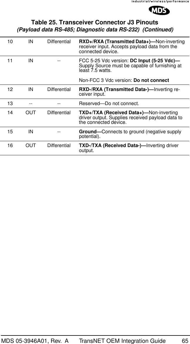
![MDS 05-3946A01, Rev. A TransNET OEM Integration Guide 63Table 24. Transceiver Connector J3 Pinouts(Payload data RS-232; Diagnostic data RS-232) Pin No. Input/Output SignalType Name/Description1IN --Ground—Connects to ground (negative supply potential).2 OUT RS-232 Diagnostic TXD—Supplies received diagnos-tic/administrative data to the connected device.3 OUT TTL, 3 Vdc Alarm condition—A low indicates normal opera-tion. A high indicates an alarm. (See ASENSE [HI/LO] command for more information.)4 IN RS-232 Diagnostic RXD—Accepts diagnostic/adminis-trative data from the connected device.5 IN -- FCC 5-25 Vdc version: DC Input (5-25 Vdc)— Supply Source must be capable of furnishing at least 7.5 watts.Non-FCC 3 Vdc version: Do not connect6 IN TTL, 3 Vdc Sleep Mode Input—A ground on this pin turns off most circuits in a remote radio. This allows for greatly reduced power consumption, yet pre-serves the radio’s ability to be brought quickly back on line. See “Sleep Mode Operation (Re-mote units only)” on Page 31 for details.7 OUT TTL, 3 Vdc Data Carrier Detect (DCD)—A low indicates hop-ping synchronization has been achieved.8 IN TTL, 3 Vdc Power Supply Shutdown Control—A ground on this pin causes the OEM module’s power supply to shut down.9 -- -- Reserved—Do not connect.10 IN RS-232, +/- 5 Vdc Transmitted Data (TXD)—Accepts payload data from the connected device.11 IN -- FCC 5-25 Vdc version: DC Input (5-25 Vdc)— Supply Source must be capable of furnishing at least 7.5 watts.Non-FCC 3 Vdc version: Do not connect12 IN RS-232, +/- 5 Vdc Request to Send (RTS)—A high causes CTS to follow after the programmed CTS delay time has elapsed (DCE).](https://usermanual.wiki/GE-MDS/DS-EL806.users-manual/User-Guide-325986-Page-71.png)
![64 TransNET OEM Integration Guide MDS 05-3946A01, Rev. A 13 -- -- Reserved—Do not connect.14 OUT RS-232, +/- 5 Vdc Received Data (RXD)—Supplies received pay-load data to the connected device.15 IN -- Ground—Connects to ground (negative supply potential).16 OUT RS-232, +/- 5 Vdc Clear to Send (CTS)—Goes high after the pro-grammed CTS delay time has elapsed (DCE), or keys an attached radio when RF data arrives (CTS KEY).Table 25. Transceiver Connector J3 Pinouts(Payload data RS-485; Diagnostic data RS-232) Pin No. Input/Output SignalType Name/Description1IN -- Ground—Connects to ground (negative supply potential).2 OUT RS-232 Diagnostic TXD—Supplies received diagnos-tic/administrative data to the connected device.3 OUT TTL, 3 Vdc Alarm condition—A low indicates normal opera-tion. A high indicates an alarm. (See ASENSE [HI/LO] command for more information.)4 IN RS-232 Diagnostic RXD—Accepts diagnostic/adminis-trative data from the connected device.5 IN -- FCC 5-25 Vdc version: DC Input (5-25 Vdc)— Supply Source must be capable of furnishing at least 7.5 watts.Non-FCC 3 Vdc version: Do not connect6 IN TTL, 3 Vdc Sleep Mode Input—A ground on this pin turns off most circuits in a remote radio. This allows for greatly reduced power consumption, yet pre-serves the radio’s ability to be brought quickly back on line. See “Sleep Mode Operation (Re-mote units only)” on Page 31 for details.7 OUT TTL, 3 Vdc Data Carrier Detect (DCD)—A low indicates hop-ping synchronization has been achieved.8 IN TTL, 3 Vdc Power Supply Shutdown Control—A ground on this pin causes the OEM module’s power supply to shut down.9 -- -- Reserved—Do not connect.Table 24. Transceiver Connector J3 Pinouts(Payload data RS-232; Diagnostic data RS-232) (Continued)](https://usermanual.wiki/GE-MDS/DS-EL806.users-manual/User-Guide-325986-Page-72.png)