GE MDS DS-ENET900ER ENET ETHERNET REMOTE User Manual 4055A entraNET Body
GE MDS LLC ENET ETHERNET REMOTE 4055A entraNET Body
UserManual.wiki
>
GE MDS
>
DS-ENET900ER User Manual
>
MANUAL
Contents
1.
MANUAL
2.
PROFESSIONAL INSTALLATION
MANUAL
Navigation menu
Upload a User Manual
Namespaces
Wiki Guide
HTML
PDF
Info
Views
User Manual
Discussion / Help
Navigation
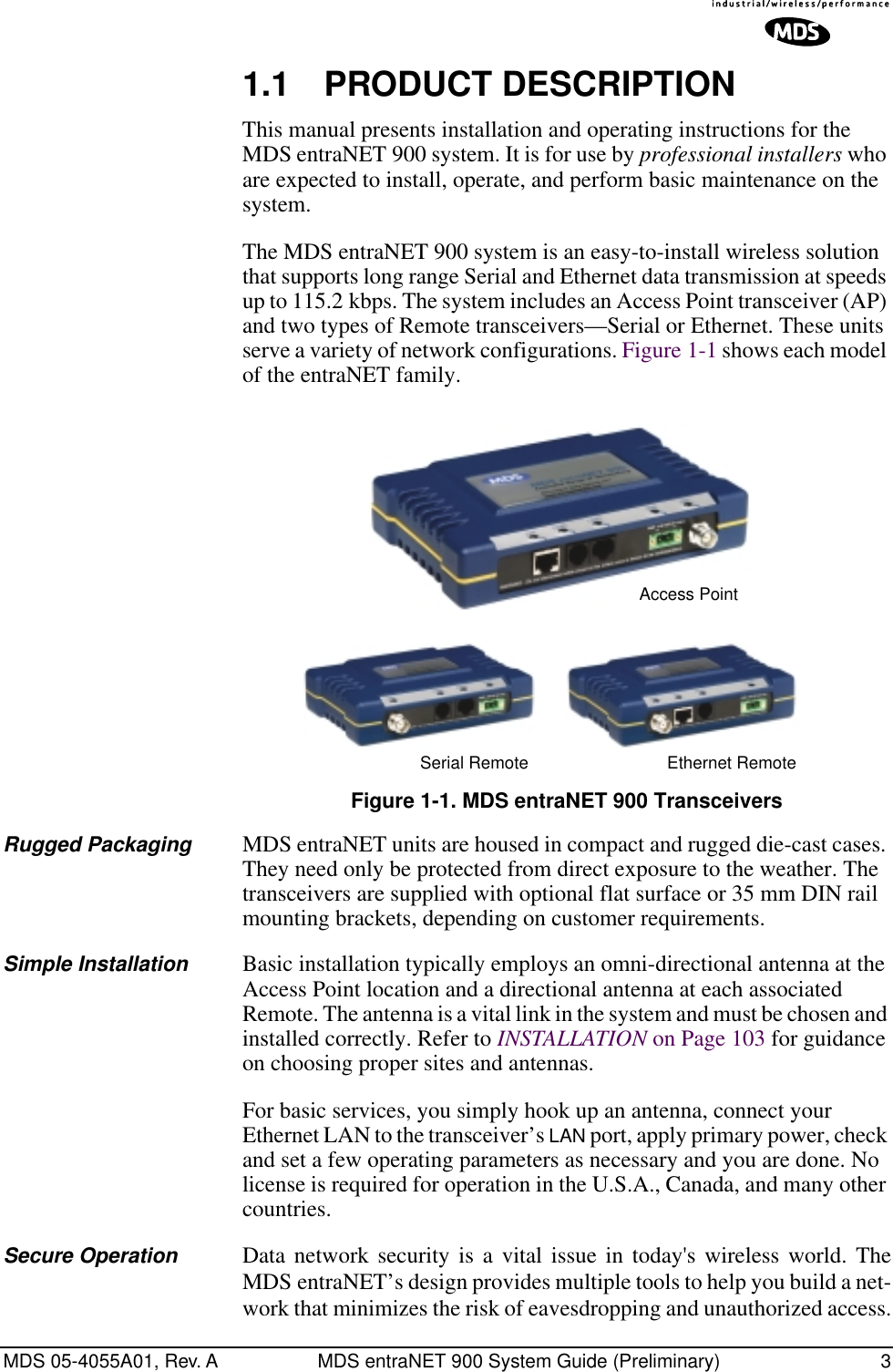
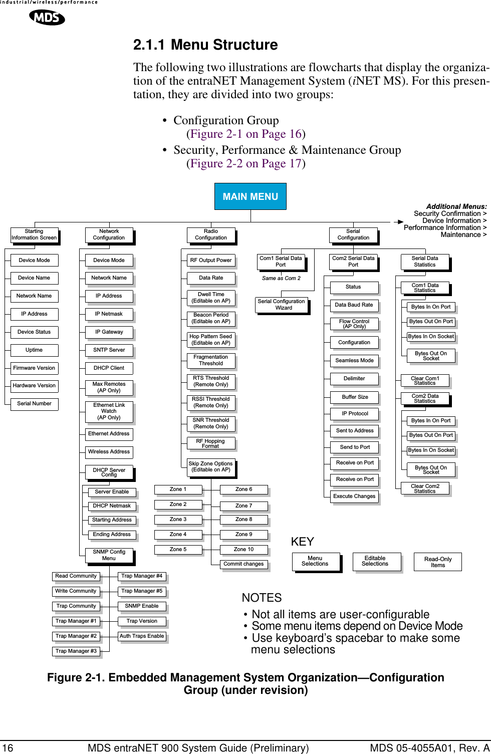
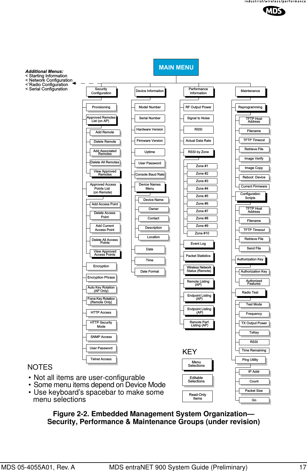
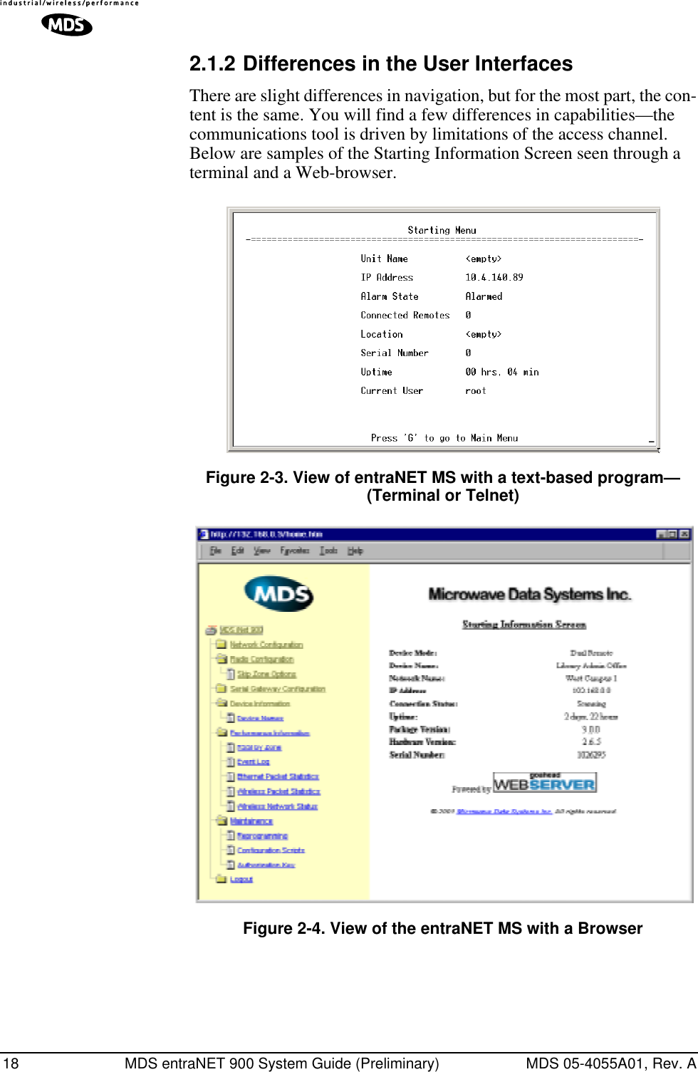
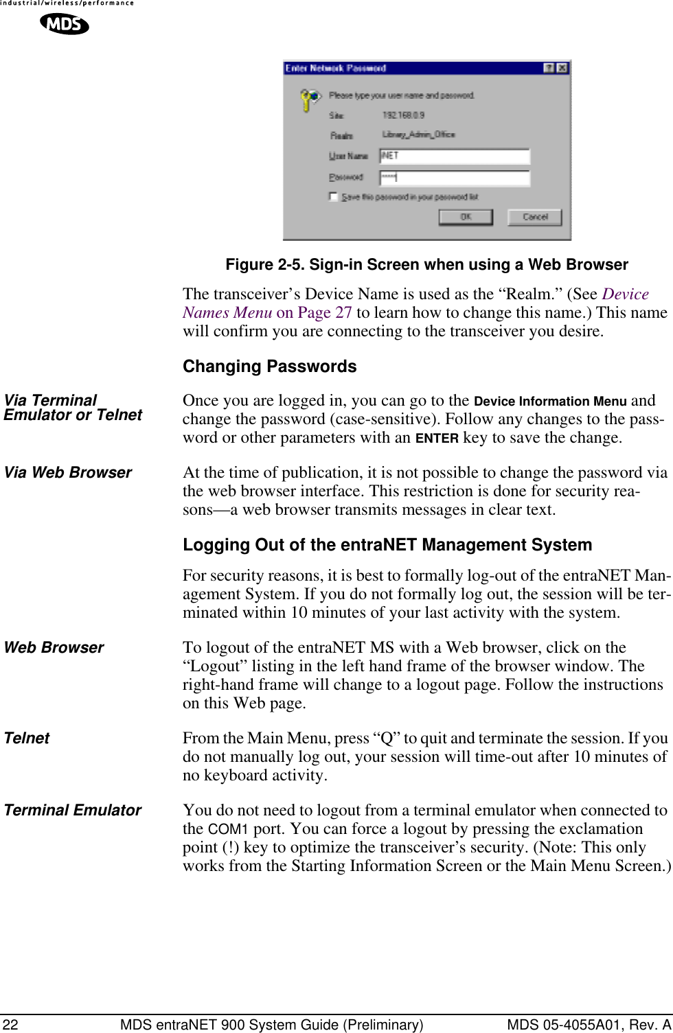
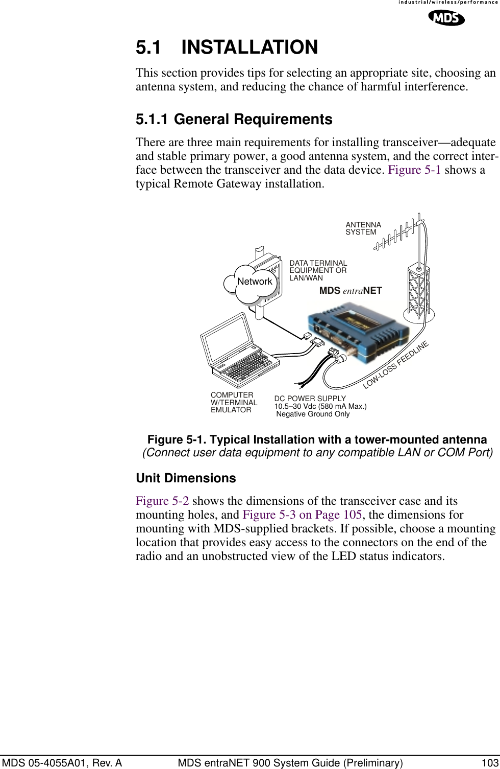
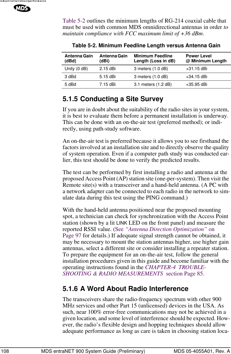
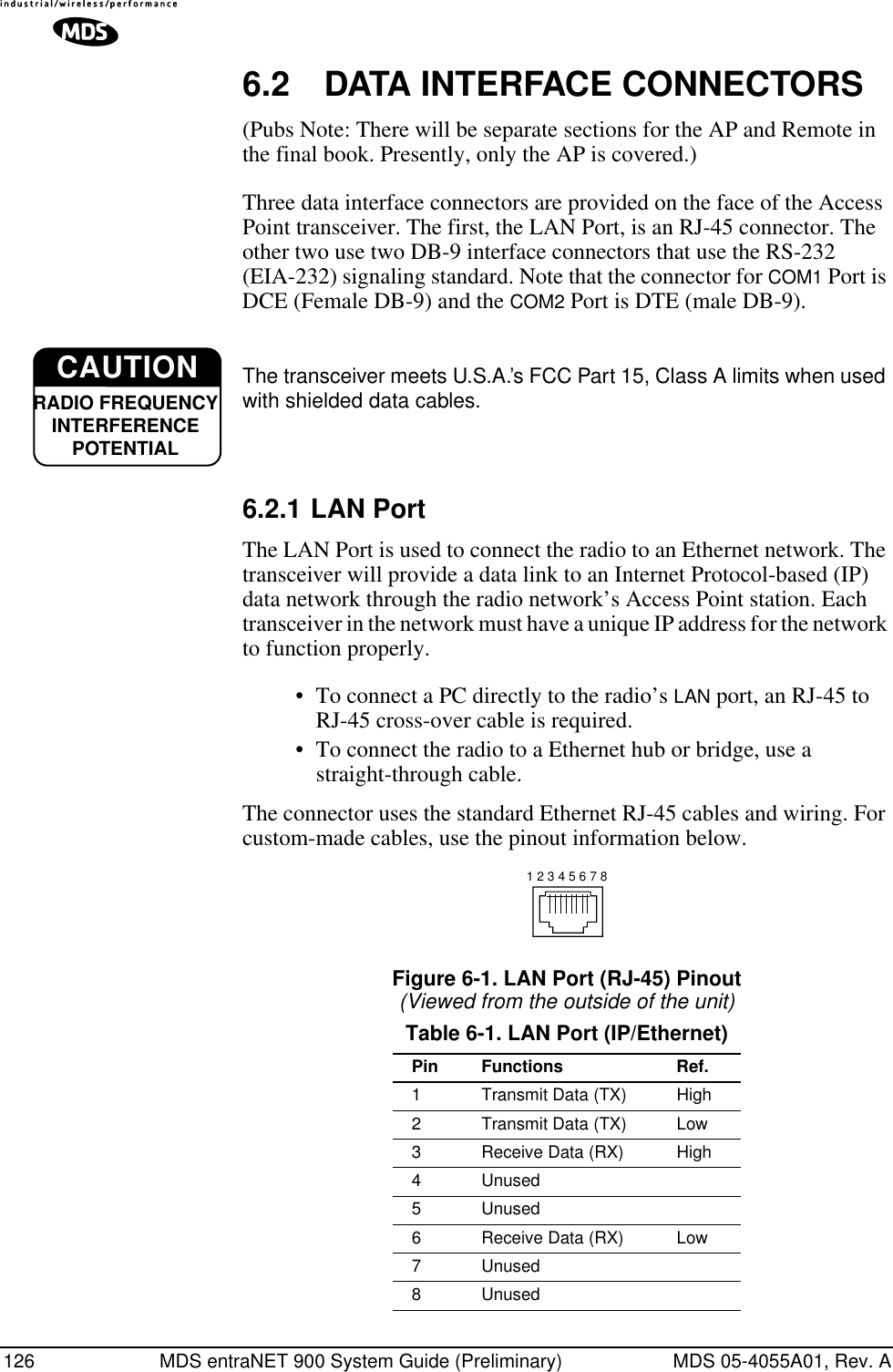
![MDS 05-4055A01, Rev. A MDS entraNET 900 System Guide (Preliminary) 152.1 INTRODUCTION The MDS entraNET 900 is equipped with an embedded management system that is accessible through different data interfaces. These include the COM1 (serial) port, the LAN (Ethernet) port and over the wireless net-work. Essentially the same capabilities are available through either of these paths.You have a choice of using three common communications tools—a computer terminal-emulator through the COM1 port, Telnet, or a Web browser through the LAN (Ethernet) port. You must know the unit IP address and the entraNET Management System password and user name to use the LAN port access. The transceiver also supports SNMP-based management tools such as Microwave Data Systems’ NETview MS™. NETview MS provides a net-work-wide management tool using a graphical user interface (GUI). For support of other software, a set of MIB files is available for download from the Microwave Data Systems’ Web site at www.microwave-data.com/service/technical/support/downloads/. A brief summary of SNMP commands can be found at SNMP Configuration section on Page 28.The entraNET Management System and its functions are divided in this guide into five functional groups that are listed below.•Section 2.3, CONFIGURING NETWORK PARAMETERS (beginning on Page 27)•Section 2.4, CONFIGURING RADIO PARAMETERS (begin-ning on Page 28)•Section 2.5, CONFIGURING THE SERIAL INTERFACES (beginning on Page 32)•Section 2.7, PERFORMANCE VERIFICATION (beginning on Page 44)•Section 2.8, MAINTENANCE (beginning on Page 58)Each of these sections has a focus that is reflected in its heading. The section you are now in will provide you with information on connecting to the entraNET Management System, how to navigate through it, and how it is structured, and how to perform some top-level configuration tasks. NOTE: Parameter options/range, and any default value, will bedisplayed at the end of the field description between squarebrackets. [range, options or description; default]](https://usermanual.wiki/GE-MDS/DS-ENET900ER.MANUAL/User-Guide-337074-Page-23.png)
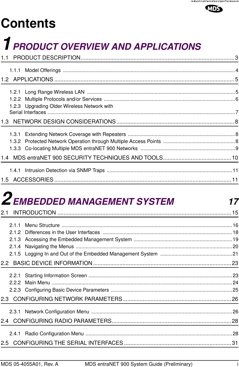
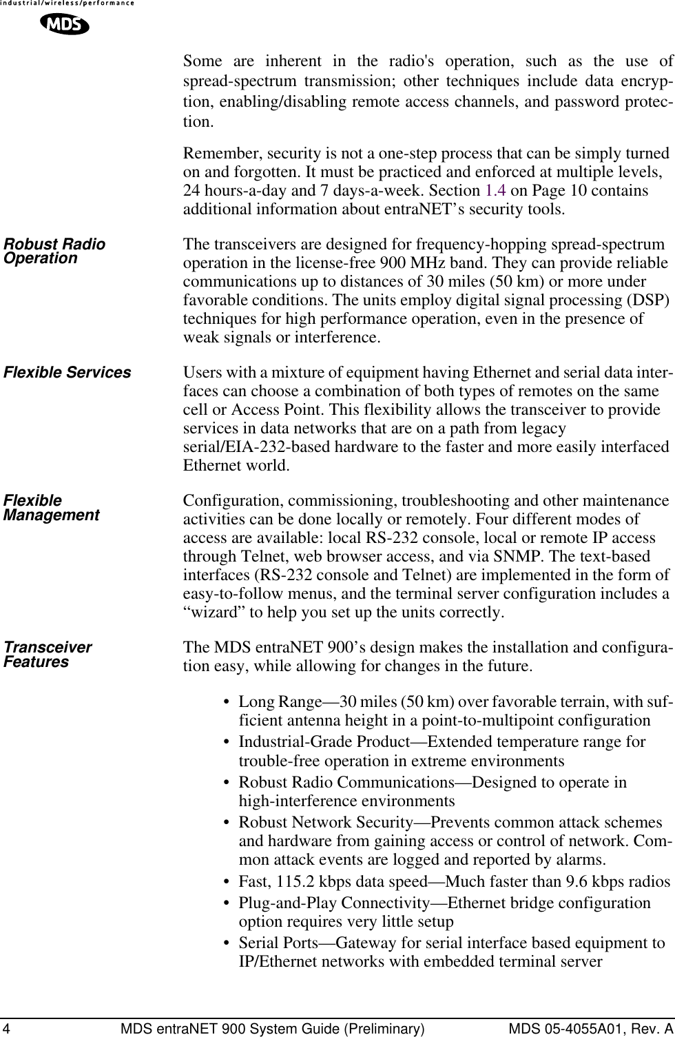
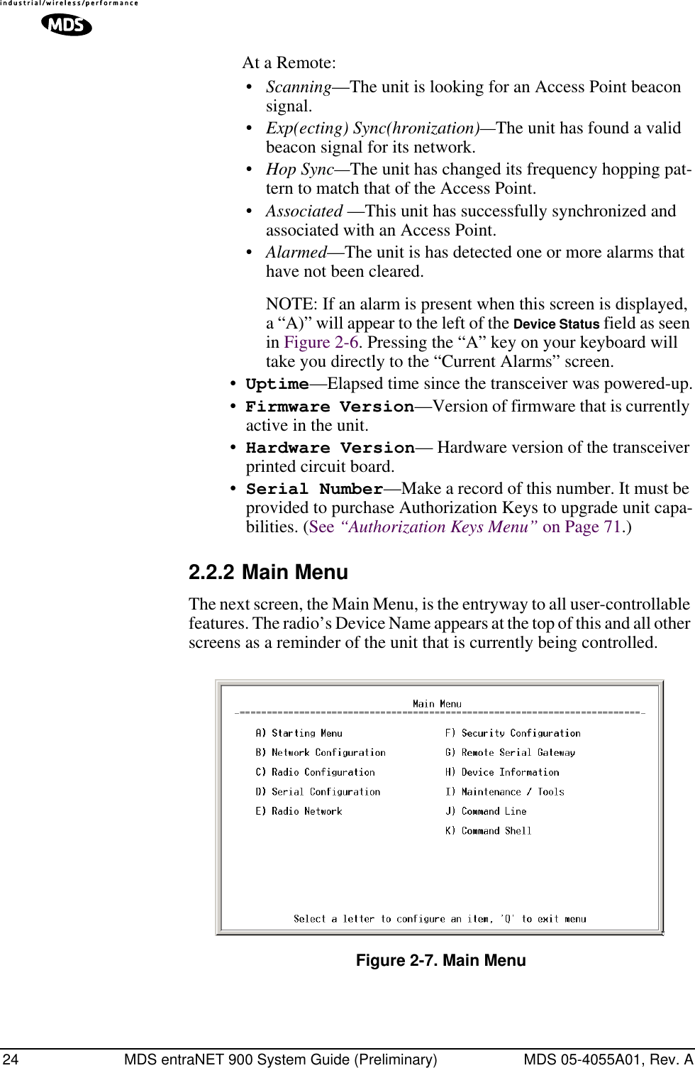
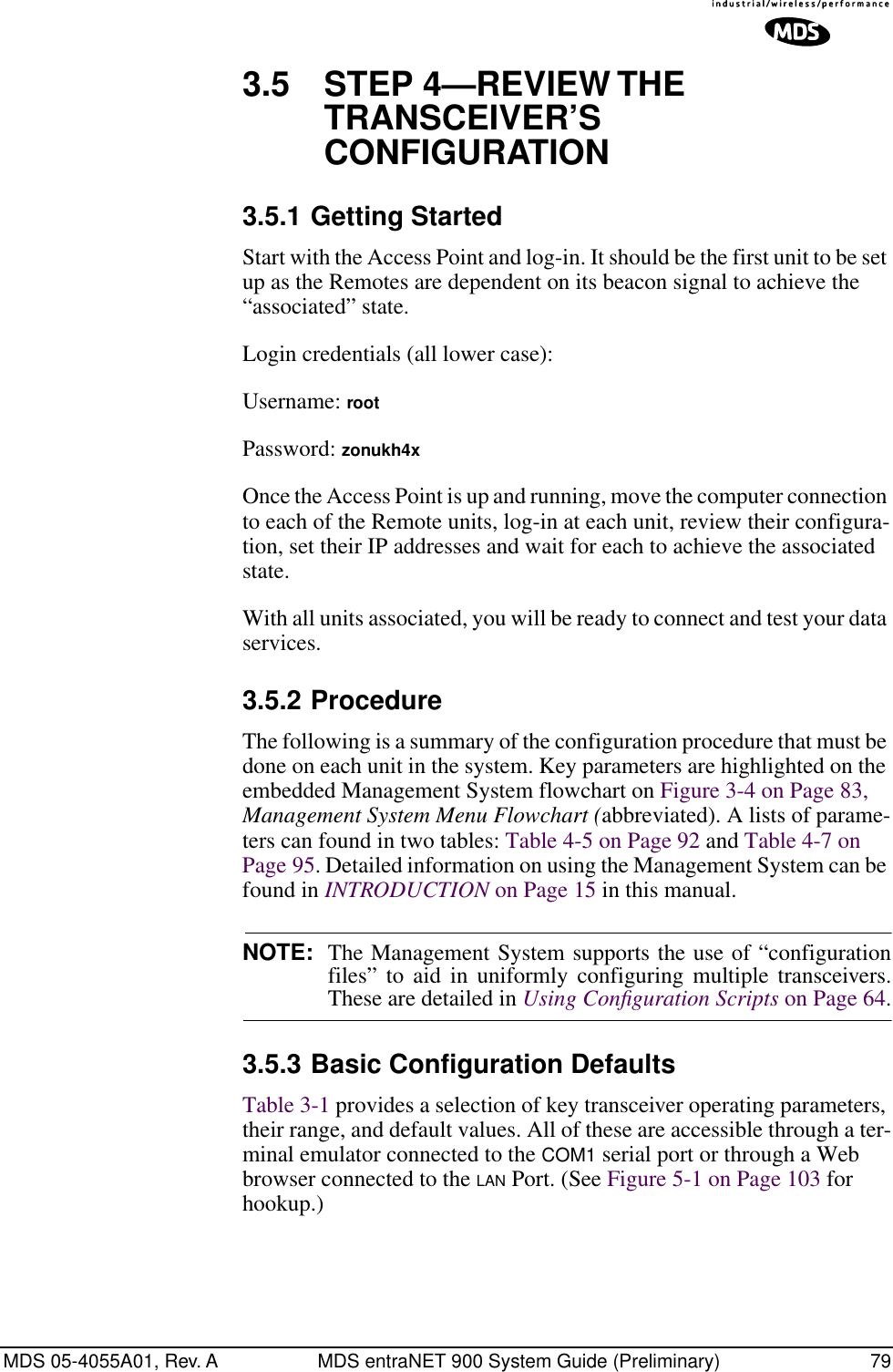
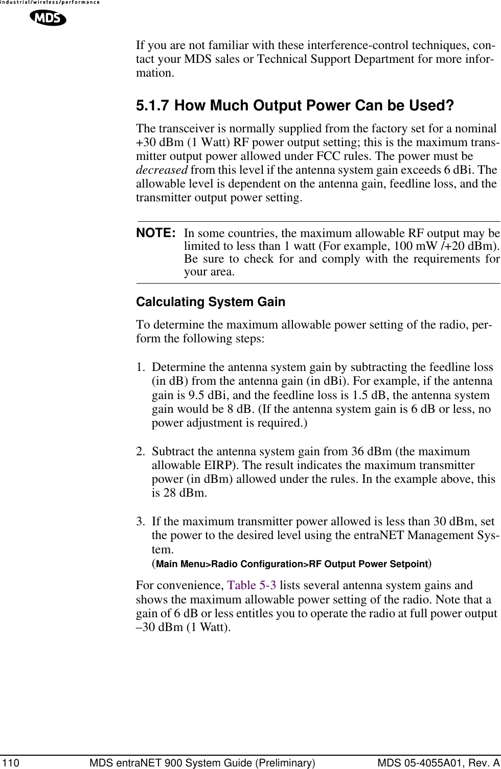
![MDS 05-4055A01, Rev. A MDS entraNET 900 System Guide (Preliminary) 232.2 BASIC DEVICE INFORMATION2.2.1 Starting Information ScreenOnce you have logged into the entraNET Management System, you will be presented with a screen that provides an overview of the transceiver and its current operating condition. It provides an array of vital informa-tion on the unit and its operating condition.Invisible place holderFigure 2-6. Starting Menu•Device Mode—Current operating mode of the unit as it relates to the network.•Device Name—This is a user-defined parameter that will appear in the heading of all pages.(To change it, see Network Configuration Menu on Page 27.)•Network Name—The name of the network in which the unit is associated.•IP Address—Unit’s IP address [192.168.1.1]•Device Status—Condition of transceiver’s association with an Access Point. At the Access Point:•Alarmed—A alarming event has been logged and not cleared.•Operational—Unit operating normally.](https://usermanual.wiki/GE-MDS/DS-ENET900ER.MANUAL/User-Guide-337074-Page-31.png)
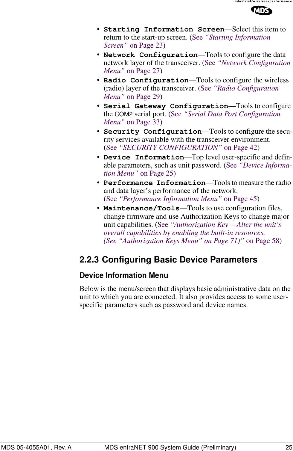
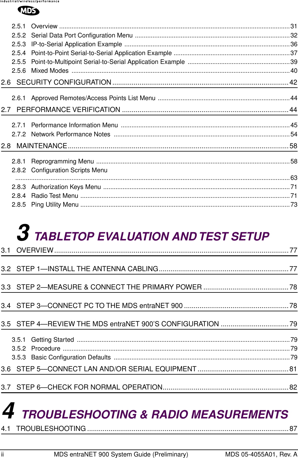
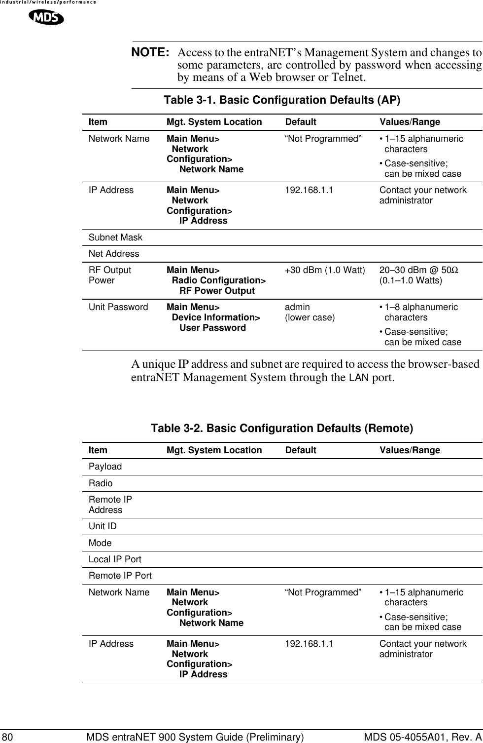
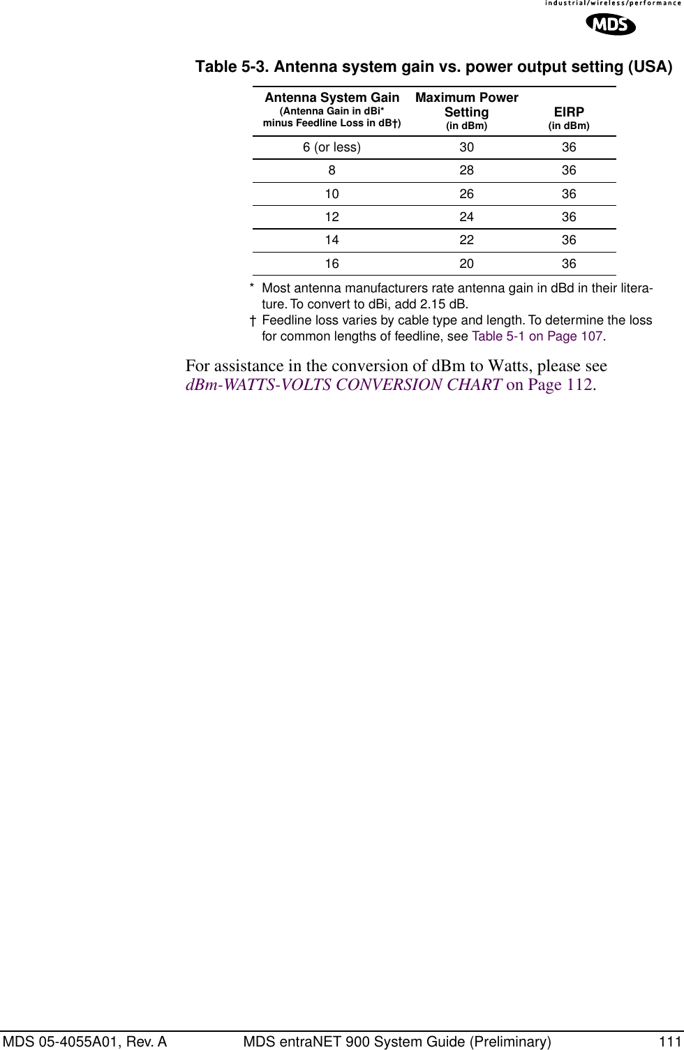
![26 MDS entraNET 900 System Guide (Preliminary) MDS 05-4055A01, Rev. AInvisible place holderFigure 2-8. Device Information Menu•Model Number (Display only)•Serial Number (Display only)•Hardware Version (Display only)•Firmware Version (Display only)—Current firmware installed and being used by the transceiver.•Uptime (Display only)—Elapsed time since powering up.•User Password—Password for gaining access to the entra-NET Management System from remote locations (over-the-air or LAN) and for changing parameters settings. Use this menu item to change the password. [admin]This menu item is always accessible via a terminal connected to the COM1 Port, and via Telnet if access enabled in the unit’s Security Configuration Menu (Page 42).•Device Names Menu—Fields used at user’s discretion for general administrative purposes. The Device Name field is used by the transceiver as the “Realm” name for network security and in the entraNET MS screen headings. (See Figure 2-9 on Page 27)•Date—Current date being used for the transceiver logs. User-setable. (Value lost with power failure if SNTP (Simple Network Time Protocol) server not accessible.) •Time—Current time of day. User-setable. Setting: HH:MM:SS (Value lost with power failure if SNTP server not accessible.)•Date Format—Select presentation format:• Generic = dd Mmm yyyy• European = dd-mm-yyyy• US = mm-dd-yyyy](https://usermanual.wiki/GE-MDS/DS-ENET900ER.MANUAL/User-Guide-337074-Page-34.png)
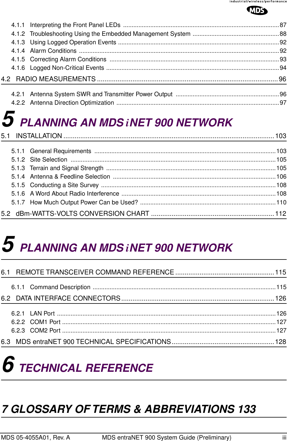
![MDS 05-4055A01, Rev. A MDS entraNET 900 System Guide (Preliminary) 27Device Names MenuFigure 2-9. Device Names Menu•Device Name—Device Name, used by the transceiver as the “Realm” name for network security and menu headings. •Owner—User defined; appears on this screen only.•Contact—User defined; appears on this screen only.•Description—User defined; appears on this screen only.•Location—User defined; appears on this screen only.2.3 CONFIGURING NETWORK PARAMETERS2.3.1 Network Configuration MenuThe Network Configuration Menu is the home of three parameters that should be reviewed and changed as necessary before placing an trans-ceiver in service—Device Mode, IP Address and Network Name. Screens for both the Access Point and Remote units are shown below.Invisible place holderFigure 2-10. Network Configuration MenuFrom Access Point•Network Name (User Review Required)—Name of the network of which this unit will be a part. Essential for association of Remotes to the Access Point in the entraNET network. [Not Programmed]•IP Address (User Review Recommended)—Essential for connec-tivity to the MDS entraNET 900 MS via the LAN port and Ether-net data over the network. Enter any valid IP address that will be unique within the network. [192.168.1.1]Screen not found in MDS entraNET](https://usermanual.wiki/GE-MDS/DS-ENET900ER.MANUAL/User-Guide-337074-Page-35.png)
![28 MDS entraNET 900 System Guide (Preliminary) MDS 05-4055A01, Rev. ACAUTION: Changing this value in the transceiver while you are communicating with it over the network, will cause a loss of communication with the transceiver. Communication will need to be re-established using the new IP address.•IP Netmask—The IPv4 local subnet mask. This field is unnecessary if DHCP is enabled. [255.255.0.0]•IP Gateway—The IPv4 address of the default gateway device, typically a router. This field is unnecessary if DHCP is enabled. [0.0.0.0]•SNTP Server—Address of server from which the transceiver will automatically get the time-of-day. Without an SNTP server, the date and time must be manually set. [0.0.0.0]•DHCP Server Config(uration)—Menu for configura-tion of DHCP services by the Access Point unit. DHCP provides on-the-fly IP address assignments to other LAN devices, includ-ing MDS entraNET 900 units. [Disabled]•DHCP Client—Enabling this option forces the transceiver (AP or Remote) to obtain an IP address from any DHCP server available on the LAN. [Disabled]•Ethernet Link Watch (Access Point Only)—Detects the lack of activity (no traffic) through the Ethernet port in the spec-ified time period. If the period expires, then all Remotes are dis-sociated and expected to re-associate with an alternate AP. The current AP will broadcast a beacon indicating its “NOT AVAILABLE” status so Remotes that hear him do not try to associate to it. Once traffic is restored this beacon signal changes to “AVAILABLE” and Remotes are allowed to join in. [Disabled]•Max(imum Allowed) Remotes (Access Point Only)—Num-ber of Remotes permitted to be associated with (served by) this Access Point. [50]•Ethernet Address (Display Only)—Hardware address of this unit’s Ethernet interface.•Wireless Address (Display Only)—Hardware address of the unit’s wireless interface.2.4 CONFIGURING RADIO PARAMETERSThere are two primary data layers in the MDS entraNET 900 network—radio and data. Since the data layer is dependent on the radio layer working properly, this is a good place to make sure the unit is configured as you want it to be. This is the primary radio menu, the Radio Config-uration Menu, and a secondary menu, the Skip Zone Options.](https://usermanual.wiki/GE-MDS/DS-ENET900ER.MANUAL/User-Guide-337074-Page-36.png)
![MDS 05-4055A01, Rev. A MDS entraNET 900 System Guide (Preliminary) 292.4.1 Radio Configuration MenuFigure 2-11. Radio Configuration MenuFrom Access Point•RF Output Power (User Review Recommended)—Set RF power output level. Displayed in dBm. Setting should reflect local reg-ulatory limitations and losses in antenna transmission line. (See “How Much Output Power Can be Used?” on Page 110 for information on how to calculate this value.) [20–30; 20]•Data Rate (Remote Only)—Over-the-air data transmission rate for this remote. Remotes can operate at different data rates when communicating with a common Access Point. 115.2 kbps data rates are possible with strong RF signal levels (> –79 dBm RSSI including a 15 dB fade margin). Data throughput will be reduced in the presence of interference due to retransmissions.The data rate value for Access Points is displayed as AP. This shows that the AP is varying the communication speed with each Remote depending on the received signal strength from each station. [115.2, AUTO; AUTO]•Dwell Time—Duration of one hop on a particular frequency in the hopping pattern. Dwell Time should be set to 32.8 ms. (This field is only changeable on an Access Point. Remotes get their value from AP upon association.) [16.4, 32.8, 65.5, 131.1, 262.1 msec; 32.8]TIP: If a packet is being transmitted and the dwell time expires, the packet will be completed before hopping to the next frequency. •Beacon Period—Amount of time between Beacon trans-missions (msec).Available Intervals: Fast (52 ms), Normal (104 ms), Moderate](https://usermanual.wiki/GE-MDS/DS-ENET900ER.MANUAL/User-Guide-337074-Page-37.png)
![30 MDS entraNET 900 System Guide (Preliminary) MDS 05-4055A01, Rev. A(208 ms), and Slow (508 ms). These values provide relatively quick association times where Fast is very fast (≈ 5 sec) and the other end, the largest recommended value, the 508 ms period is slow (≈ 60 sec). [Fast, Normal, Moderate Slow; Normal]TIP: Increasing the Beacon Period will provide a small improvement in network data throughput. Shortening it decreases the time needed for Remotes to associate with the AP. A short period is usually only a benefit when there are mobile Remotes in the network.•Hop Pattern Seed (Access Point Only)—A user-selectable value to be added to the hop pattern formula in an unlikely event of identical hop patterns of two co-located or nearby networks. Changing the seed value will minimize possible RF-signal col-lisions of transceivers. (This field is only changeable on an Access Point. Remotes read the AP’s value upon association.) [1 to 65,000; 1]•Fragment Threshold—Before transmitting over the air, if a packet exceeds this number of bytes, the transceiver sends the packet in multiple fragments that are reassembled before being delivered over the Ethernet interface at the receiving end. Use smaller values on high interference locations. (See “Network Performance Notes” on Page 54.) [(256–1600 bytes; 1600]TIP: In an interference-free environment this value should be large to maximize throughput. If interference exists then the value should be set to smaller values. The smaller the packet the less chance of it being interfered with at the cost of slightly reduced throughput.•RTS Threshold—Number of bytes for the over-the-air RTS/CTS handshake boundary. (See “Network Performance Notes” on Page 54.) [0 to 1600 bytes; 500]TIP: Lower the RTS Threshold as the number of Remotes or overall over-the-air traffic increases. Using RTS/CTS is a trade-off, giving up some throughput in order to prevent collisions in a busy over-the-air network.The RTS Threshold should be enabled and set with a value smaller than the Fragmentation Threshold described above. RTS forces the Remotes to request permission from the AP before sending a packet. The AP sends a CTS control packet to grant permission to one Remote. All other Remotes stop transmitting for the specified amount of time.•RSSI Threshold—Level (dBm) below which connection is deemed to have degraded, and an critical event is generated and logged. [0 to -120; Not Programmed]](https://usermanual.wiki/GE-MDS/DS-ENET900ER.MANUAL/User-Guide-337074-Page-38.png)
![MDS 05-4055A01, Rev. A MDS entraNET 900 System Guide (Preliminary) 31•SNR Threshold—Value (dB) below which the wireless net-work connection is deemed to have degraded and an critical event is generated and logged. [0 to 40; Not Programmed]•Hop Format—Operation compliant to country-specific restrictions into the frequency hopping algorithm. This option must be specified when the order is placed and cannot be mod-ified in the field by the user. Authorizations at time of publica-tion:• Australia: 915–928 MHz band• Brazil: 902-907.5 and 915-928 MHz bands• U.S.A. & Canada: 902–928 MHz bandNOTE: Other country-specific configurations may be available. Check with your MDS sales representative for new additions.•Skip Zones (Editable at Access Point Only)—Display of current utilization of zones. Each zone consists of eight RF channels. (See “Skip Zone Options Menu” on Page 31.)Skip Zone Options Menu Invisible place holderFigure 2-12. Skip Zones Menu(“Commit changes” displayed only on Access Point units)This is a display of current utilization of 10 zones, each of eight RF operating frequencies. Zones can be toggled between Active and Skipped at Access Point units by first keying in the letter of the zone to be changed, and then pressing the spacebar to toggle between the two options for each zone. Select the Commit Changes menu item to implement changes. These changes will be forwarded to all units in the network through the Access Point’s beacon signal.A maximum of three zones can be skipped and still be compliant with FCC regulations.](https://usermanual.wiki/GE-MDS/DS-ENET900ER.MANUAL/User-Guide-337074-Page-39.png)
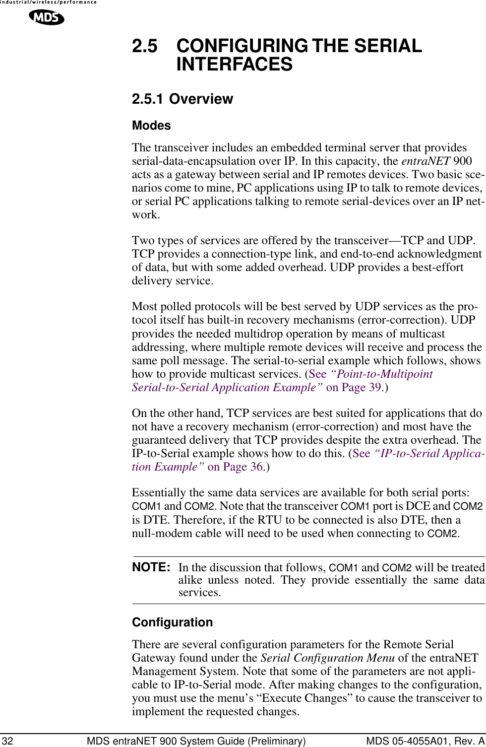
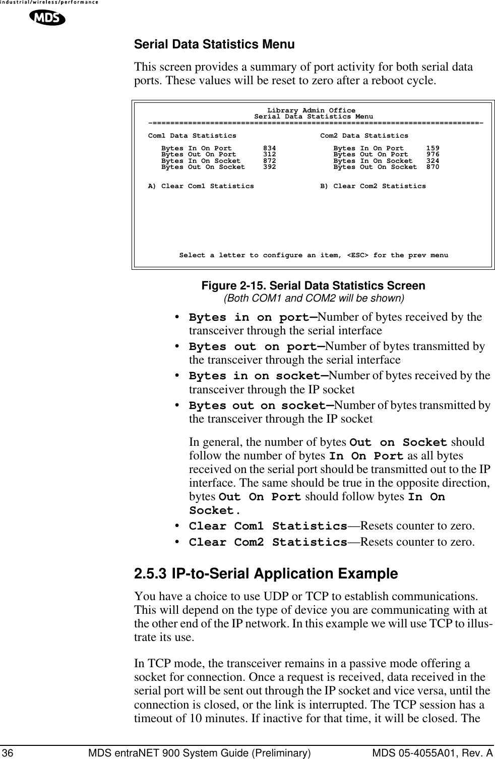
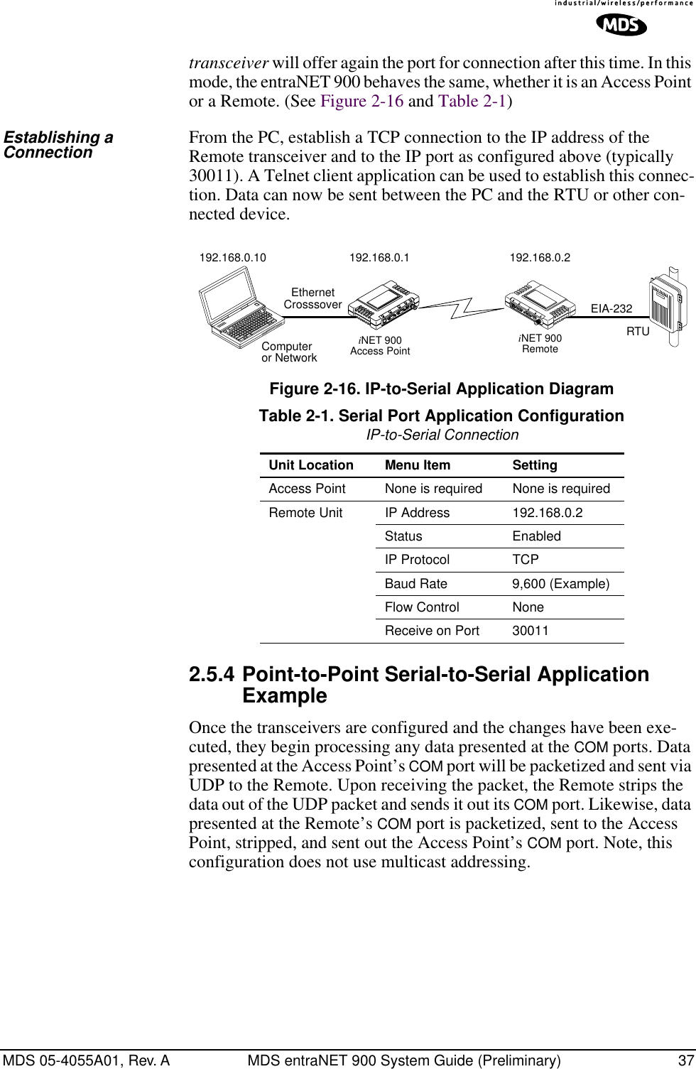
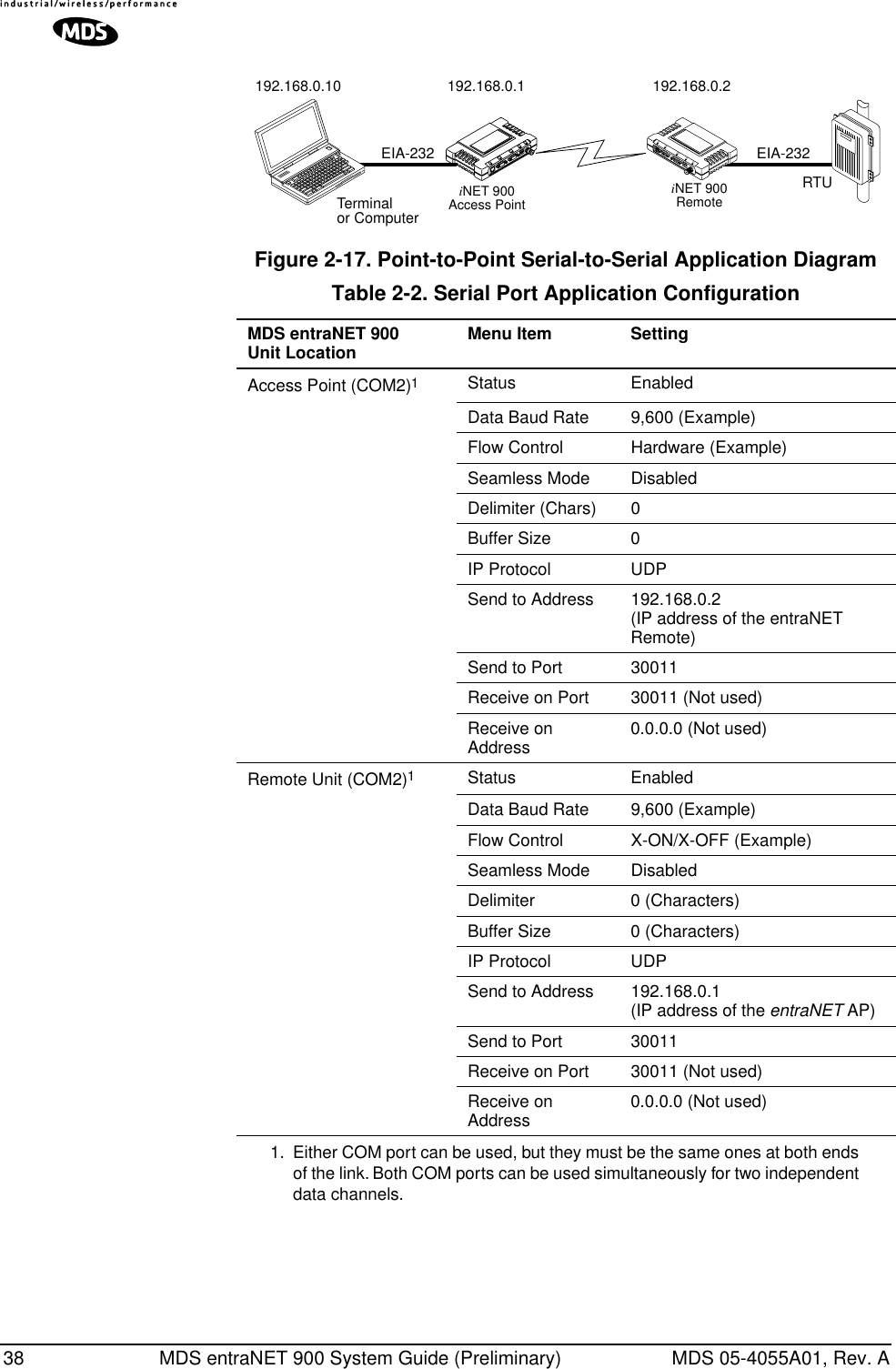
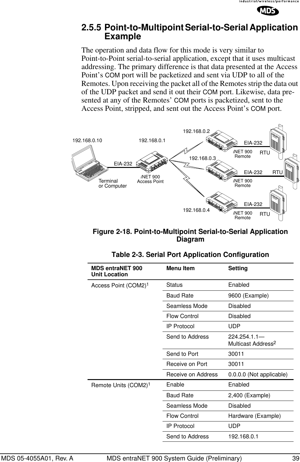
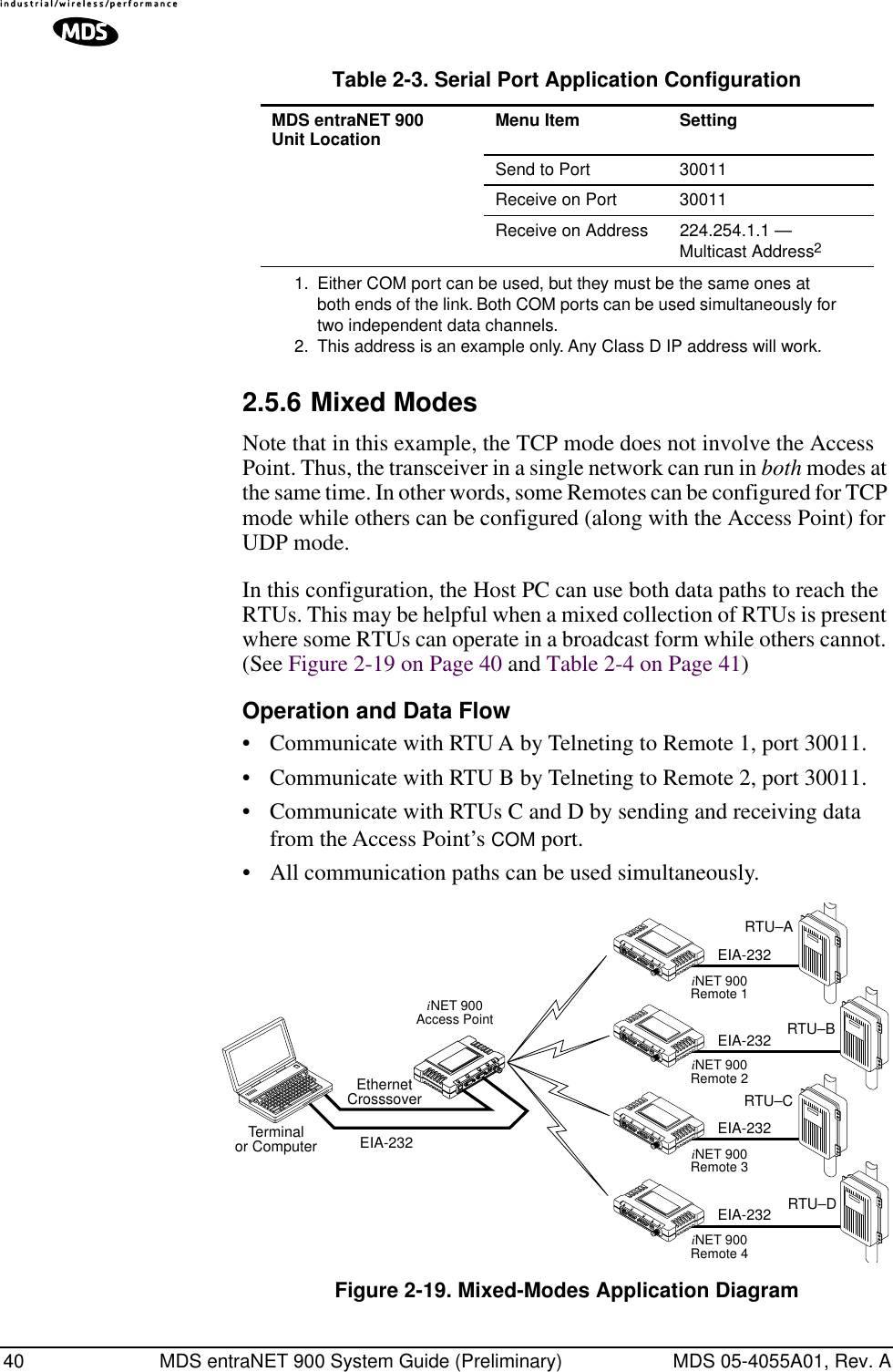
![34 MDS entraNET 900 System Guide (Preliminary) MDS 05-4055A01, Rev. ASerial Data Port Configuration ScreensFigure 2-14. COM1/2—Serial Gateway Configuration ScreenNOTE: Setting this parameter for COM1 port to Enable prevents accessof the entraNET Management System (MS) through this port. However, the entraNET MS can still be accessed via Telnet orbrowser through the LAN port.TIP: If you need to restore the COM1 port to support entraNET Man-agement System services, connect a terminal to the port and enter an escape sequence to reset it the console mode. (+++ ENTER)•Status—Enable/Disable the serial data port. •Data Baud Rate—Data rate (payload) for the COM port in bits-per-second. [1,200–115,200; 19200] •Configuration—Interface signaling parameters. Data bits, parity and stop bits. [7N1, 7E1, 7O1, 8N1, 8E1, 8O1; 8N1]•Flow Control [Com2 Only] (Access Point Only)—RTS/CTS handshaking between the transceiver and con-nected device. [Enable, Disable; Disabled]•Seamless Mode— If data buffering is Enabled, the radio will operate in seamless mode. Data bytes will be sent over the air as quickly as possible, but the receiver will buffer the data until enough bytes have arrived to cover worst case gaps in transmission. The delay introduced by data buffering may range from 22 to 44 ms, but the radio will not create any gaps in the output data stream. This mode of operation is required for protocols such as MODBUS™ that do not allow gaps in their data transmission. [Enable, Disable; Disabled]•Delimiter— Number of characters that represent the end of a message (inter-character time-out). A transceiver receiv-ing data through the serial port will send an end-of-message](https://usermanual.wiki/GE-MDS/DS-ENET900ER.MANUAL/User-Guide-337074-Page-42.png)
![MDS 05-4055A01, Rev. A MDS entraNET 900 System Guide (Preliminary) 35signal to the remote end. MODBUS defines a “3.5-character” parameter. [0–1,000; 0]•Buffer Size—Maximum amount of characters, that the Remote end will buffer locally before starting to transmit data through the serial port. [0–100; 4]•IP Protocol—TCP (Transmission Control Protocol) or UDP (User Datagram Protocol). [TCP, UDP; TCP]This is the type of IP port that will be offered by the trans-ceiver serial device server. UDP requires configuration of Send to Address parameter. NOTE: TCP has guaranteed deliv-ery, but at the expense of more overhead; UDP delivery is not guaranteed, but has less overhead.•Send to Address—The IP address to be used as a des-tination for data received through the serial port. To reach multiple Remotes in the network, use a multicast address at the AP. Remotes in the network should have the multicast address programmed in their Send to Address. [Any legal IP address; 0.0.0.0]•Send to Port—The IP port to which data packets received from the device connected to the transceiver should be sent. [Any valid IP port; COM1: 30010, COM2: 30011]•Receive on Port—Receive IP data from this source and pass it through to the connected serial device. The port num-ber must be used by the application connecting to local TCP socket. [Any valid IP port; COM1: 30010, COM2: 30011]•Receive on Address—Must be configured with a valid multicast address. IP packets received with a matching desti-nation address will be terminated at this unit[Any legal IP address; 0.0.0.0]Used only for UDP multicast purposes•Execute Changes—Save and execute changes made on this screen (Shown only after changes have been entered.)](https://usermanual.wiki/GE-MDS/DS-ENET900ER.MANUAL/User-Guide-337074-Page-43.png)
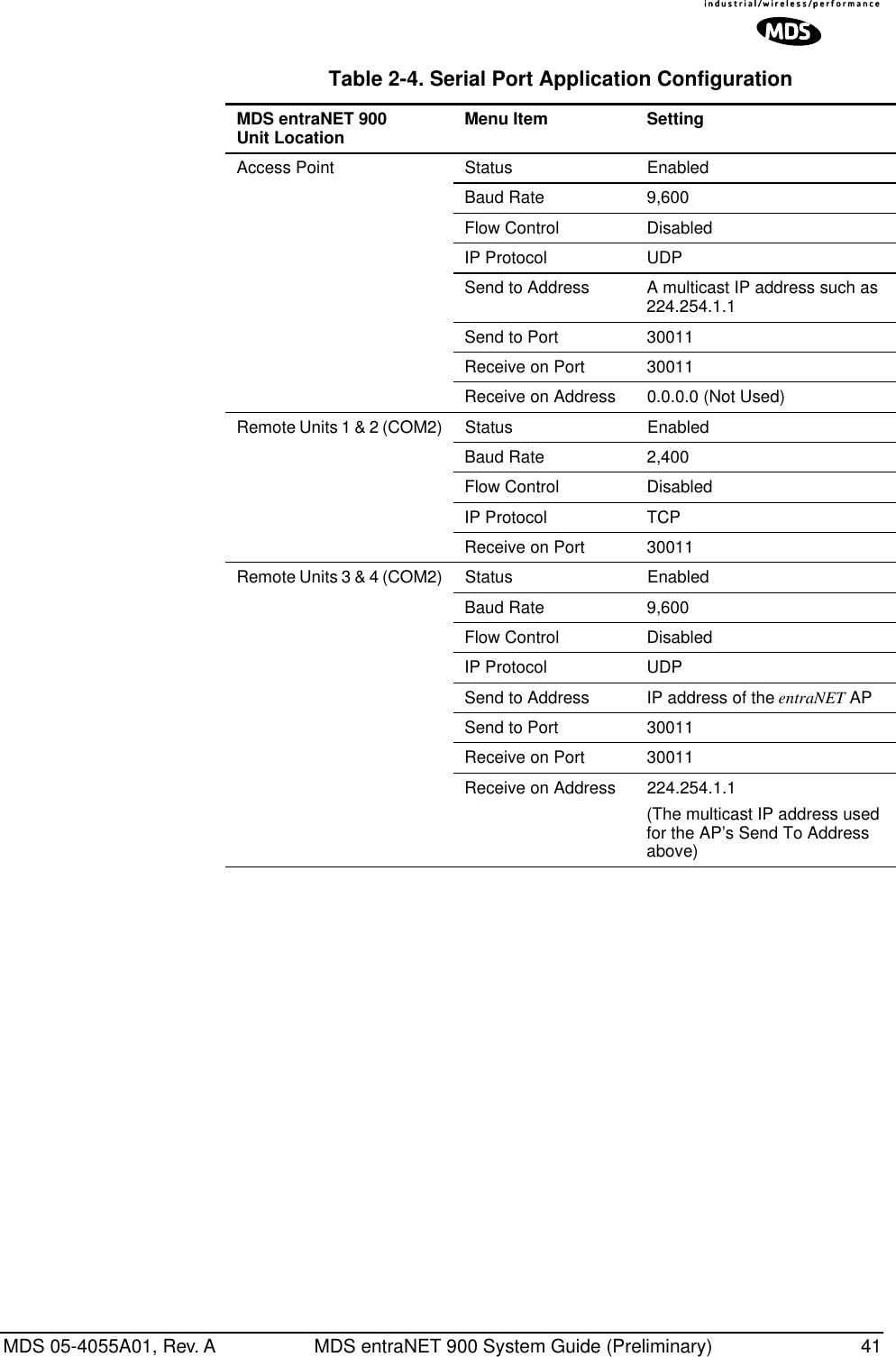
![42 MDS entraNET 900 System Guide (Preliminary) MDS 05-4055A01, Rev. A2.6 SECURITY CONFIGURATIONThere are many options for assisting you in providing secondary secu-rity for your transceivers and the network. These options start with con-trolling remote access to the network via Telnet, Web Browser, and SNMP. Other areas include multiple levels of encryption and MD5-level security for HTTP connections. Figure 2-20. Security Configuration Menu(Access Point Version Shown)•Provisioning— Enable provisioning at the Remote. [Enabled/Disabled; Disabled]Enabling forces the entraNET 900 to check the Approved AP List before continuing the authorization process. In the case of a Remote, the AP must be in the Approved Access Points List before it accepts the beacon as valid. In the case of an AP, a Remote must be in the Approved Remotes List to be granted authorization. Before enabling this option, at least one entry must already exist in the Approved List.•Encryption— Enable encryption of over-the-air data pack-ets. [Enabled, Disabled; Disabled]Enabling forces the transceiver to use 128-bit encryption on all over-the-air messages. This option requires the Encryption Phrase to be previously configured.•Auto Key Rotation—Enable automatic rotation of encryption keys. [Enabled, Disabled; Disabled]Enabling forces the transceiver to use the key rotation algorithm to generate a new encryption key after 500 kilobytes of informa-tion has been transmitted, or one hour has elapsed. Key rotation prevents reusing encryption data that could result in key-crack-ing, unlike standard 802.11b communications that rely on static encryption keys.•HTTP Access—Prevents remote access through HTTP (Web browser) on Port 80 [Enabled/Disabled; Disabled] MIS Wireless IP Host Security Configuration Menu -==========================================================================- A) Provisioning enabled G) Approved Remotes List B) Encryption disabled H) Encryption Phrase ******** C) Auto Key Rotation disabled I) Force Key Rotation D) HTTP Access disabled J) HTTP Security Mode Basic Auth E) SNMP Access disabled K) User Password ******** F) Telnet Access enabled Select a letter to configure an item, <ESC> for the prev menu](https://usermanual.wiki/GE-MDS/DS-ENET900ER.MANUAL/User-Guide-337074-Page-50.png)
![MDS 05-4055A01, Rev. A MDS entraNET 900 System Guide (Preliminary) 43•SNMP Access— Prevents remote access through SNMP com-mands on Port 161 [Enabled, Disabled; Enabled]•Telnet Access—Prevents remote access through Telnet sessions on Port 23 [Enabled, Disabled; Enabled]•Approved Access Points/Remotes List (Menu)—Go to menu providing the creation and management list of units permitted (provisioned) with which this unit will be permitted to communicate.•Encryption Phrase—Phrase (text & numbers) that will be part of the encryption algorithm. [Any 30-character alphanu-meric string; Blank]•Force Key Rotation— It triggers an immediate key rota-tion of the encryption keys before the internal counters do it automatically.•HTTP Security Mode—Select security mode/level of login via HTTP browser. HTTP Access disabled prevents access through HTTP. HTTP Security Mode is functional if HTTP Access is enabled. [Basic Auth, MD5 Digest; Basic Auth]Basic mode requires a password, but the actual password text is transmitted in the clear (unencrypted). MD5 is the most secure. MD5 Digest protects/encrypts the password but is only supported by Microsoft’s Internet Explorer™ browser at the time of publication.User Password—General administrative password only for this unit. Used at log-in via COM1 Port, Telnet and Web browser. [Up to 8-character alphanumeric string without spaces (case-sensitive); Default=admin]TIP: For enhanced security, consider using a misspelled word. This helps protect against sophisticated hackers who may use a database of common words (e.g., dictionary file) to determine a password.](https://usermanual.wiki/GE-MDS/DS-ENET900ER.MANUAL/User-Guide-337074-Page-51.png)
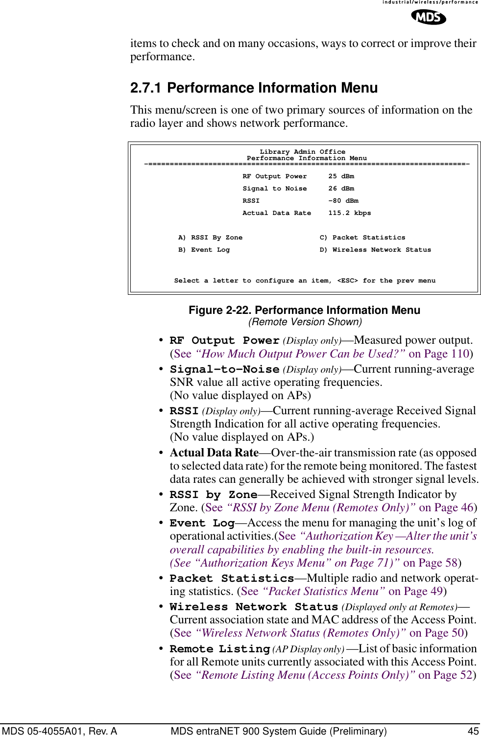
![44 MDS entraNET 900 System Guide (Preliminary) MDS 05-4055A01, Rev. A2.6.1 Approved Remotes/Access Points List MenuThis menu is the same for both Access Points and Remotes and the names change to reflect their mode. Replace “Remotes” with Access Points” in the following description. Figure 2-21. Approved Remotes List Menu•Add Remote—Enter MAC address of Remote.[Any valid 6-octet MAC address; 00:00:00:00:00:00] •Delete Remote—Enter MAC address of Remote.For security purposes, you may want to delete a stolen or depro-visioned radio.•Add Associated Remotes—Add all currently associated remotes (1-255) to the approved remote list. Alternatively, you can enter each Remote MAC manually.•Delete All Remotes—Remove (complete purge) of all Remotes from current list.•View Approved Remotes—Simple listing of approved Remotes by MAC address, of radios authorized to join this AP. If a Remote is not in this list, it will not be able to associate with this AP.•Save Changes—Save all changes made during this session with this menu. Changes will be implemented only if they are “saved” before exiting this menu.2.7 PERFORMANCE VERIFICATIONAfter the basic operation of the radio has been checked, you may wish to optimize the network’s performance using some of the following sug-gestions. The effectiveness of these techniques will vary with the design of your system and the format of the data being sent.There are two major areas for possible improvement—the radio and the data network. The following sections will provide you with a variety of MIS Wireless IP Host Approved Remotes List Menu -==========================================================================- A) Add Remote 00:06:3D:00:0B:D7 Remote Added B) Delete Remote 00:00:00:00:00:00 C) Add Associated Remotes D) Delete All Remotes E) View Approved Remotes F) Save Changes Select a letter to configure an item, <ESC> for the prev menu](https://usermanual.wiki/GE-MDS/DS-ENET900ER.MANUAL/User-Guide-337074-Page-52.png)
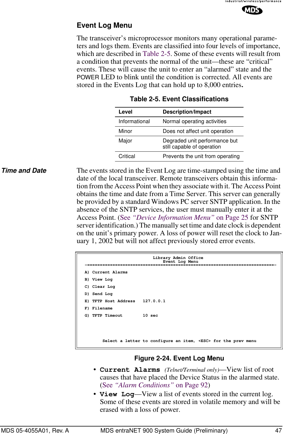
![48 MDS entraNET 900 System Guide (Preliminary) MDS 05-4055A01, Rev. A•Clear Log—Purges the log of all eventsTIP: Save your Event Log before choosing to clear it in order to retain potentially valuable troubleshooting information. (See “Upgrading the Firmware” on Page 59 for an over-view on how to transfer files from the transceiver to a computer on the network using TFTP.)•Send Log (Telnet/Terminal only)—Initiate TFTP transfer of the unit’s event Event Log in a plain text (ASCII) file to a TFTP server at the remote location.•TFTP Host Address (Telnet/Terminal only)—IP address of the computer on which the TFTP server resides. [Any valid IP address; 127.0.0.1]•Filename (Telnet/Terminal only)—Name to be given to the Event Log file sent to the TFTP server for archiving. [Any 40-char alphanumeric string; Blank]NOTE: You may want to change it to reflect the type of log you intend to archive and/or its date. •TFTP Time-out (Telnet/Terminal only)—Time in seconds the TFTP server will wait for a packet ACK (acknowledgment) from the transceiver before suspending the file transfer.[10 to 120 seconds; 10]View Current AlarmsFigure 2-25. Current Alarms Screen Library Admin Office Current Alarms -==========================================================================- EVENT_BRIDGE Select a letter to configure an item, <ESC> for the prev menu](https://usermanual.wiki/GE-MDS/DS-ENET900ER.MANUAL/User-Guide-337074-Page-56.png)
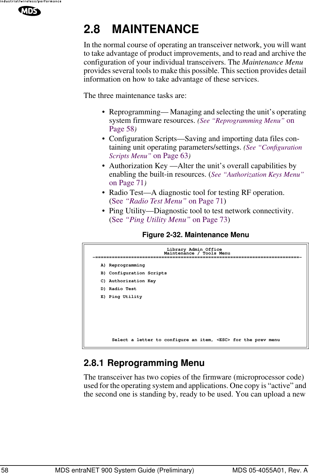
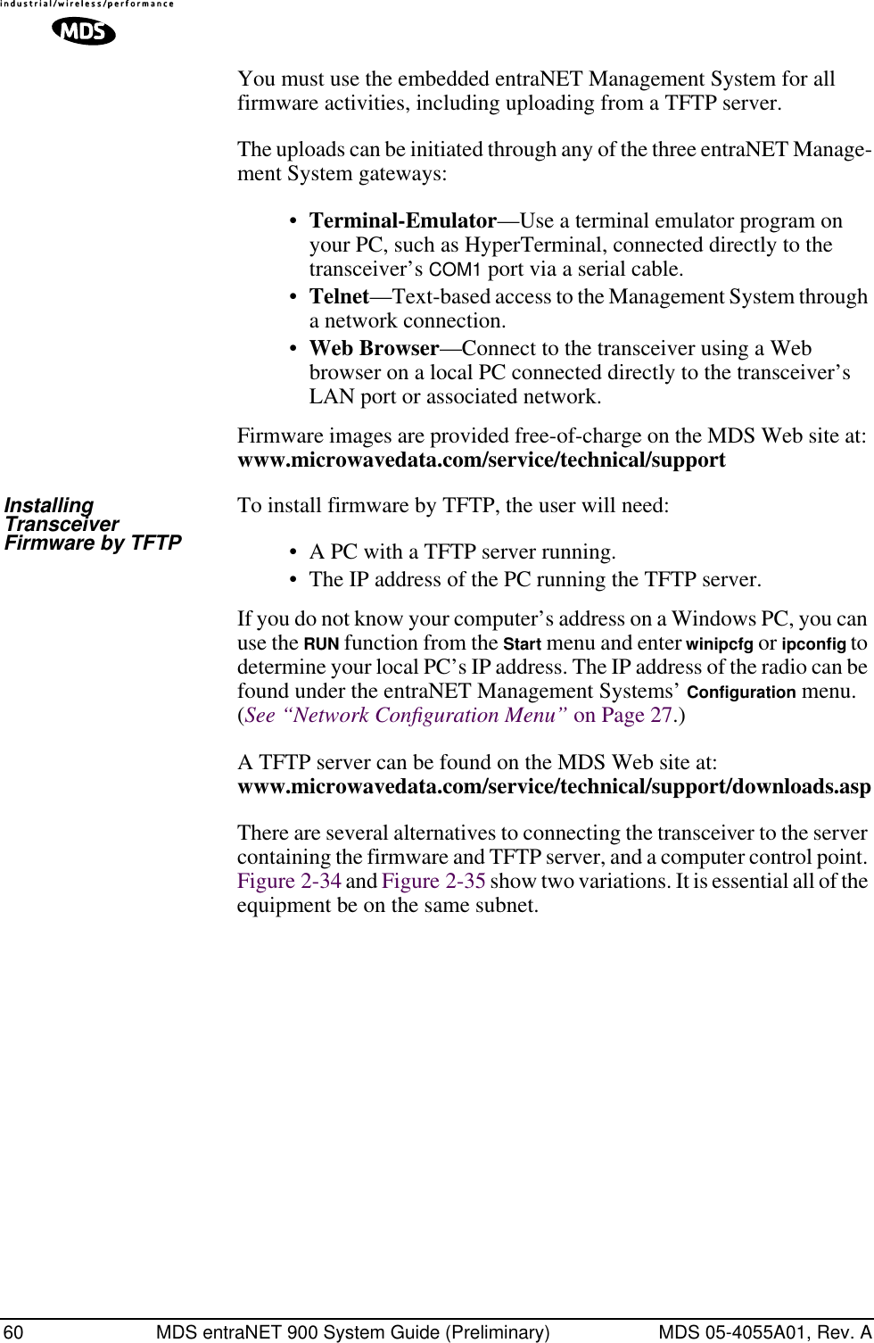
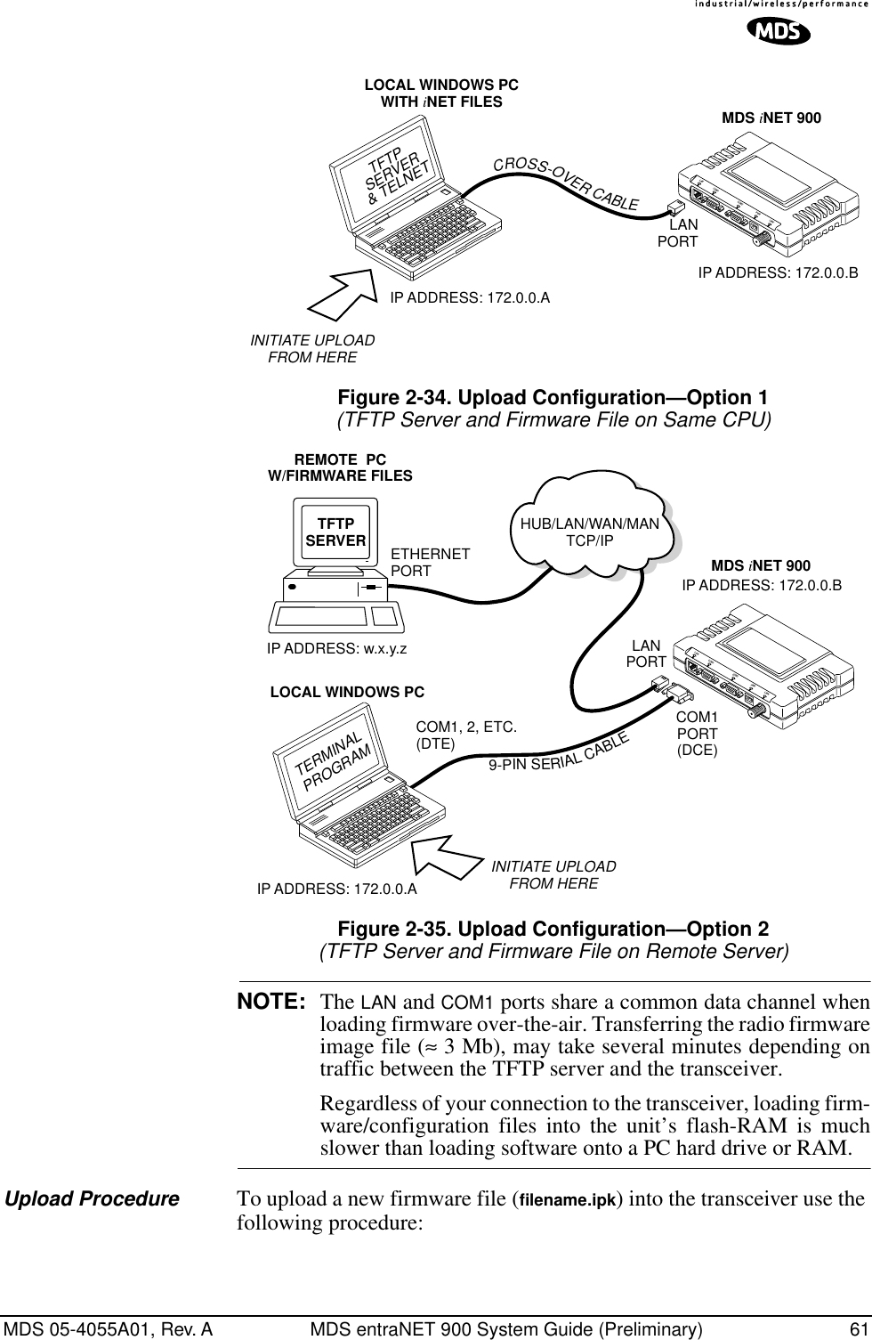
![MDS 05-4055A01, Rev. A MDS entraNET 900 System Guide (Preliminary) 59release into the inactive position and place it in service whenever you desire. Figure 2-33. Reprogramming Menu(Shown with “Image Copy” Selected)•TFTP Host Address—IP address of the host computer from which to get the file. [Any valid IP address]•Filename—Name of file to be received by the TFTP server.[Any 40-character alphanumeric string] Verify that this corre-sponds to the TFTP directory location. May require sub-direc-tory, for example: br\inet-bkrf-3_1_0.ipk. •TFTP Timeout—Time in seconds the TFTP server will wait for a packet ACK (acknowledgment) from the transceiver before suspending the file transfer. [10 to 120 seconds; 10]•Retrieve File—Initiate the file transfer from the file from TFTP server. Placed into inactive firmware position in the trans-ceiver’s non-volatile memory [Y, N]•Image Verify—Initiate the verification of the integrity of firmware file held in unit.•Image Copy—Initiate the copying of the active firmware into the inactive image.•Reboot Device—Initiate rebooting the transceiver. This will interrupt data traffic through this unit, and the network if performed on an Access Point. Intended to be used to toggle between firmware images.NOTE: See “Upgrading the Firmware” on Page 59 for details on setting up the TFTP server.Upgrading the FirmwareFrom time-to-time MDS will offer upgrades to the transceiver firmware. One version of the firmware provides core software resources for all radio models. Uploading new firmware into the unit will not alter any privileges provided by Authorization Keys and does not require the transceiver to be taken off-line until you want to operate the unit from the new firmware image in the unit. Library Admin Office Reprogramming Menu-==========================================================================- A) TFTP Host Address 10.4.2.1 B) Filename entranet-bkrf-3_1_0.ipk C) TFTP Timeout 120 sec D) Retrieve File E) Image Verify F) Image Copy G) Reboot Device Current Firmware Image 1: 1.1.0 (active) Image 2: 1.1.0 Select a letter to configure an item, <ESC> for the prev menu](https://usermanual.wiki/GE-MDS/DS-ENET900ER.MANUAL/User-Guide-337074-Page-67.png)
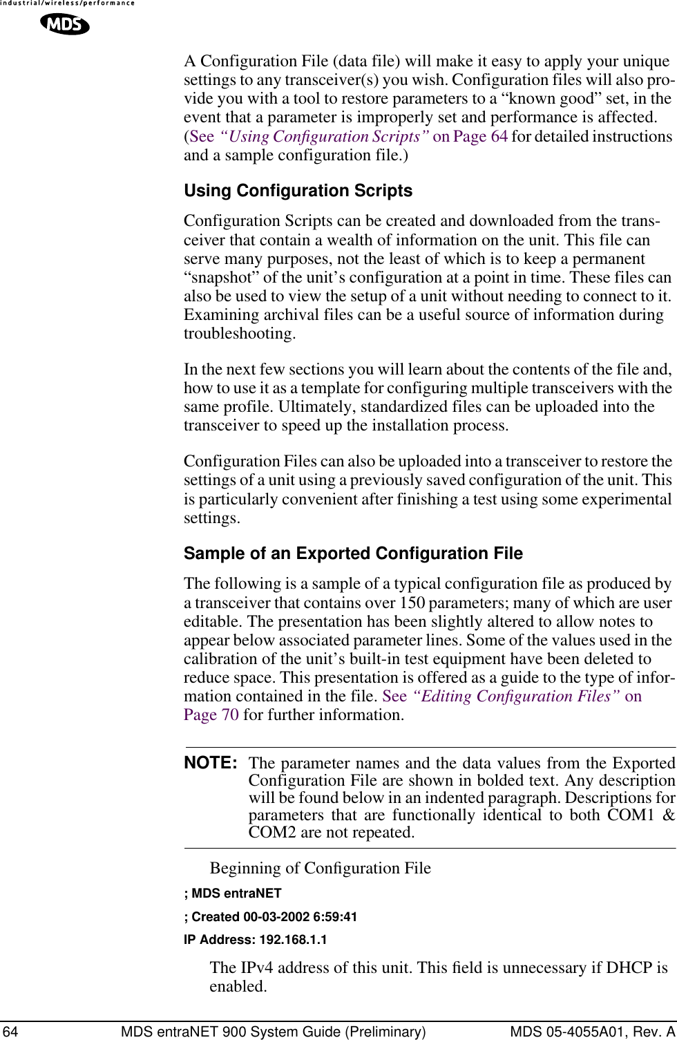
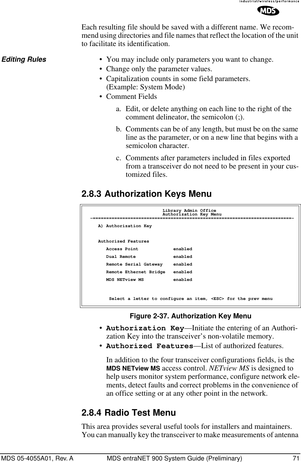
![MDS 05-4055A01, Rev. A MDS entraNET 900 System Guide (Preliminary) 632.8.2 Configuration Scripts MenuFigure 2-36. Configuration Files Menu•TFTP Host Address—IP address of the computer on which the TFTP server resides. [Any valid IP address]•Filename—Name of file containing this unit’s configuration profile that will be transferred to the TFTP server. The configu-ration information will be in a plain-text ASCII format.[Any 40-character alphanumeric string] May require sub-direc-tory, for example: config\inet-config.txt. (See “Using Configura-tion Scripts” on Page 64)NOTE: The filename field is used in identifying the desired incoming file and as the name of file being exported to the TFTP server. Before exporting the unit’s configuration, you may want to name it something that reflect the unit’s services or identifi-cation.•TFTP Timeout—Time in seconds the TFTP server will wait for a packet ACK (acknowledgment) from the transceiver before suspending the file transfer. [10 to 120 seconds; 10]•Retrieve File—Initiate the file transfer of the configura-tion file from TFTP server into the transceiver.•Send File—Initiate the file transfer from the transceiver’s current configuration file to TFTP server.NOTE: See “Upgrading the Firmware” on Page 59 for details on setting up the TFTP server.A brief description of configuration filesIf you plan to have more than a few transceivers in your network, use the configuration file feature to configure similar units from a common set of parameters. There are over 50 user-controllable settings that can be used to optimize the network and saved into a Configuration File. How-ever, only four essential parameters need to be reviewed and altered to use the file with another transceiver. Library Admin Office Configuration Scripts Menu -==========================================================================- A) TFTP Host Address 127.0.0.0 B) Filename C) TFTP Timeout 20 sec D) Retrieve File E) Send File Select a letter to configure an item, <ESC> for the prev menu](https://usermanual.wiki/GE-MDS/DS-ENET900ER.MANUAL/User-Guide-337074-Page-71.png)
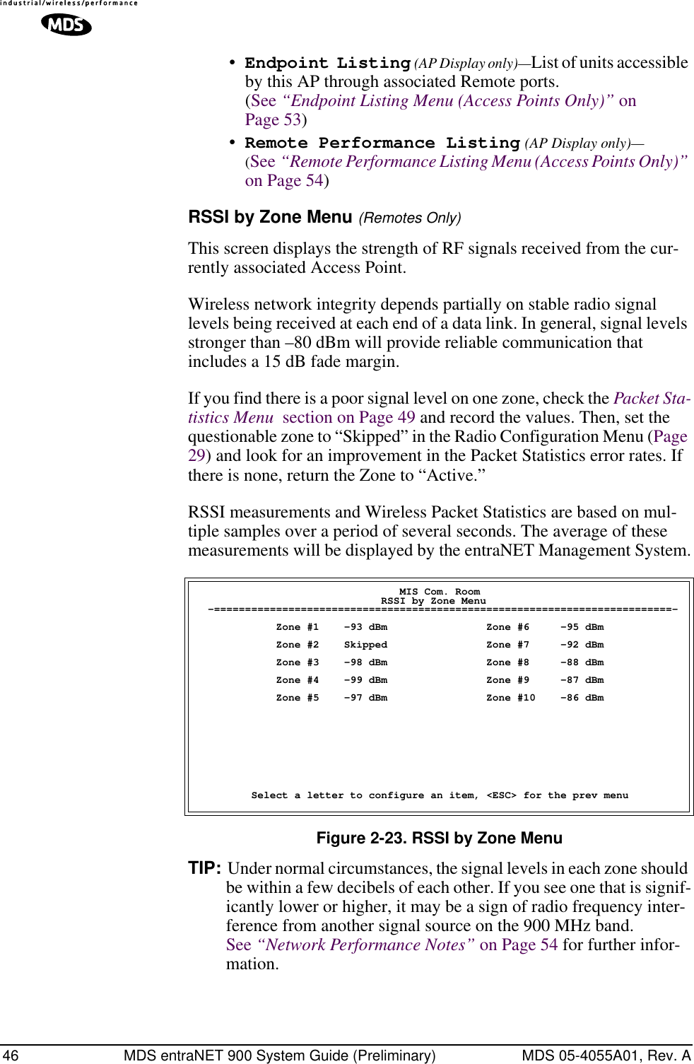
![72 MDS entraNET 900 System Guide (Preliminary) MDS 05-4055A01, Rev. Aperformance. (See “Antenna Direction Optimization” on Page 97 for details.Figure 2-38. Radio Test MenuShown with Test Mode EnabledNOTE :Use of the test mode will disrupt traffic through this unit. If theunit is the Access Point, it will disrupt traffic through the entirenetwork.Test Mode function is automatically limited to 10 minutes andshould only be used to measure transmit power. It may also bemanually reset to continue with the testing or turned off.•Test Mode—Controls access to the transceiver’s suite of tools. [(ON, OFF; OFF]•Frequency—Set radio operating frequency during the testing period to a single frequency. [915.0000 MHz]•TX Output Power—Temporarily overrides the power level setting in the Radio Configuration Menu. [20]•TxKey—Manually key the radio transmitter for power mea-surements. [Enable, Disable; Disable]•RSSI—Incoming received signal strength on frequency entered in the frequency parameter on this screen (–dBm). This RSSI measurement is updated more frequently than the RSSI by Zone display of the Performance Information menu. Library Admin Office Radio Test Menu -==========================================================================- A) Test Mode ON B) Frequency 915.000000 MHz C) TX Output Power 25 dBm D) TxKey disabled RSSI -67 dBm Time Remaining 09:50 Select a letter to configure an item, <ESC> for the prev menu](https://usermanual.wiki/GE-MDS/DS-ENET900ER.MANUAL/User-Guide-337074-Page-80.png)
![MDS 05-4055A01, Rev. A MDS entraNET 900 System Guide (Preliminary) 732.8.5 Ping Utility MenuFigure 2-39. Ping Utility Menu•IP Addr—Address to send a PING. [Any valid IP address]•Count—Number of PING packets to be sent.•Packet Size—Size of each PING data packet (bytes).•Go—Send PING packets to address shown on screen.Screen will be replaced with detailed report of PING activity. Press any key after viewing the results to return to this menu. Library Admin Office Ping Utility Menu -==========================================================================- A) IP Addr 192.168.1.1 B) Count 4 C) Packet Size 32 D) Go Select a letter to configure an item, <ESC> for the prev menu](https://usermanual.wiki/GE-MDS/DS-ENET900ER.MANUAL/User-Guide-337074-Page-81.png)


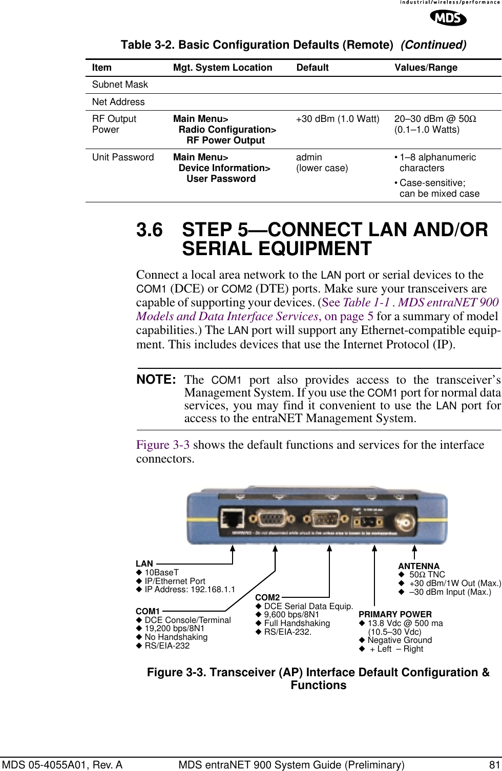

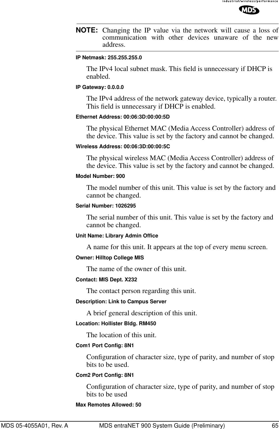
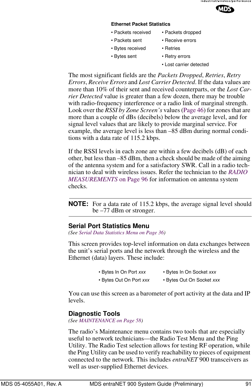
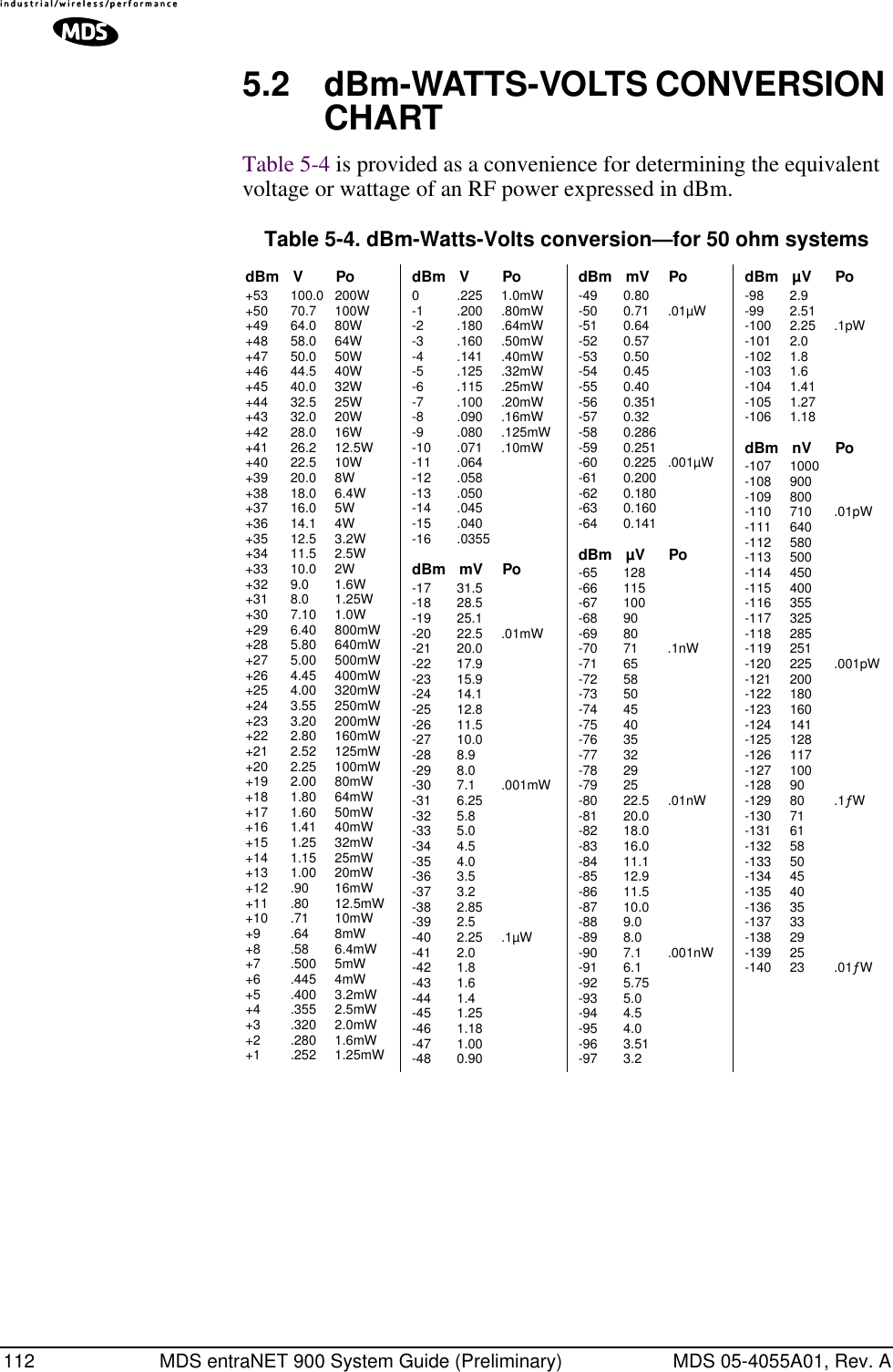
![MDS 05-4055A01, Rev. A MDS entraNET 900 System Guide (Preliminary) 89The following is a summary of how several screens in the entraNET Management System can be used as diagnostic tools. For information on how to connect to the entraNET Management System See “STEP 3—CONNECT PC TO THE MDS TRANSCEIVER” on Page 78. Starting Information Screen(See Starting Information Screen on Page 23)The entraNET MS’s “home page” provides some valuable bits of data. Probably the most important is the “Device Status” field. This one item will tell you if the unit is showing signs of life. If the Device Status field says “associated,” then look in the network areas beginning with network data statistics. If it displays some other Cannot access the entraNET MS through COM1a. Connect to unit via Telnet or Web browserb. Disable the serial mode for COM1(Serial Gateway Configuration>Com1 Serial Data Port>Status>Disabled) or, if you know the unit’s data configurationa. Connect to COM 1 via a terminal set to VT100 and the port’s data baud rate.b. Type “+++ [ENTER]”c. Change the terminal’s baud rate to match the transceiver’s Console Baud Rate.d. Type “+++ [ENTER]”Display on terminal/Telnet screen garbleda. Verify the terminal/terminal emulator or Telnet application is set to VT100Cannot pass IP data to WAN. a. Verify your IP settings.b. Use the PING command to test communication with transceivers in the local radio system.c. If successful with local PING, attempt to PING an IP unit attached to a radio.d. If successful with the LAN PINGs, try connecting to a known unit in the WAN.Wireless Retries too high. Possible Radio Frequency Interference—a. If omnidirectional antennas are used, consider changing to directional antennas. This will often limit interference to and from other stations.b. Try skipping some zones where persistent interference is known or suspected.c. The installation of a filter in the antenna feedline may be necessary. Consult the factory for further assistance.Password forgotten. a. Connect to the transceivertransceiver using a terminal through the COM1 Port.b. Call MDS. Get a password-resetting Authorization Key.c. Enter the Authorization Key at the login prompt as a password.Table 4-2. Basic Troubleshooting with the entraNET MS Symptom Problem/Recommended System Checks](https://usermanual.wiki/GE-MDS/DS-ENET900ER.MANUAL/User-Guide-337074-Page-97.png)


![MDS 05-4055A01, Rev. A MDS entraNET 900 System Guide (Preliminary) 1156.1 REMOTE TRANSCEIVER COMMAND REFERENCE6.1.1 Command DescriptionThe following commands are used to set the configuration and operating parameters for the MDS entraNET radio...They can be issued from a console terminal connected as shown in Section...HELPLists the commands available through the console interface.HELP DUMP TOR RADIOLOGIN AUTH BOOT DATECOM1 CONSOLE PAYLOAD OEMREG POWER WAKE TRENDENCRYPT REPROG H2H VERDEVICE CONFIG CONFIGTAB IMAGEDUMPLists the current value of all variables.TORSyntax: TOR [optional arguments as follows]...<COMMAND> command string to send to TOR PASS=<choices> 0 ;COM2 passthrough to/from TOR LCP data port DISABLED 1 ;COM1 passthrough to/from TOR diagnostic port 2 ;COM2 passthrough to/from TOR LCP data port REPROG=<choices> 0 ;reprogram tor with image for currently executing OIB image.](https://usermanual.wiki/GE-MDS/DS-ENET900ER.MANUAL/User-Guide-337074-Page-123.png)
![116 MDS entraNET 900 System Guide (Preliminary) MDS 05-4055A01, Rev. A1 ;reprogram tor with image 1 2 ;reprogarm tor with image 2 CMD=<0|1> dump command line format RADIOSyntax: RADIO [optional arguments as follows]...ADDR=<integer> Current Radio Network Address MAC=<integer> Current Radio MAC Address SYNC=<integer> Current state of Radio Sync CMD=<0|1> dump command line format LOGINSyntax: LOGIN [optional arguments as follows]...<PASS> Login securely; prompt username + password and echo '*' when inputting password. ADMIN=<string> Administrator console login password. DIST=<string> Distributor console login password. NONE=<string> User Read-only login. FACT=<string> ENG=<string> AUTHSyntax: AUTH [optional arguments as follows]...<CODE=> ELI_NOT_BLUNET ;1: ELI; 0: BLUNET MAC_UNIT_MASTER ;1: MASTER; 0: REMOTE RS232_NOT_4XX ;1: RS232; 0: RS485](https://usermanual.wiki/GE-MDS/DS-ENET900ER.MANUAL/User-Guide-337074-Page-124.png)
![MDS 05-4055A01, Rev. A MDS entraNET 900 System Guide (Preliminary) 117 ETHERNET_ENABLE ;1: ETHERNET ENABLED; 0: DISABLED NETWKMGMT_ENABLE ;1: NETWORK MANAGEMENT ENABLED; 0: DISABLED CMD=<0|1> dump command line format BOOTSyntax: BOOT [optional arguments as follows]...RUN=<choices> RESET ;goto Reset Vector APP1 ;Application Image 1 APP2 ;Application Image 2 CMD=<0|1> dump command line format DATESyntax: DATE [optional arguments as follows]...<DATE> Current real time clock date. FORM=<choices> US ;US Date Format EUROPE ;Europe Date Format GENERIC ;Generic Date Format TIME=<string> Current system time-of-day in military format CMD=<0|1> dump command line format COM1Syntax: COM1 [optional arguments as follows]...MODE=<choices> CMDL ;Console port in Command-line mode](https://usermanual.wiki/GE-MDS/DS-ENET900ER.MANUAL/User-Guide-337074-Page-125.png)
![118 MDS entraNET 900 System Guide (Preliminary) MDS 05-4055A01, Rev. A DATA ;Console port in transparent data mode DLINK ;Console port in DLINK remote diagnostic mode. CMD=<0|1> dump command line format CONSOLESyntax: CONSOLE [optional arguments as follows]...BAUD=<choices> Data Rate of Console Port (COM1):1200 ;1200 bps 2400 ;2400 bps 4800 ;4800 bps 9600 ;9600 bps 19200 ;19200 bps 38400 ;38400 bps 57600 ;57600 bps 115200 ;115200 bps CBITS=<choices> Number of Bits that form one character (byte):7 ;7 character bits 8 ;8 character bits 9 ;9 character bits PAR=<choices> NONE ;no parity ODD ;odd parity EVEN ;even parity SBITS=<choices> 1 ;1 stop bit 2 ;2 stop bits CMD=<0|1> dump command line format](https://usermanual.wiki/GE-MDS/DS-ENET900ER.MANUAL/User-Guide-337074-Page-126.png)
![MDS 05-4055A01, Rev. A MDS entraNET 900 System Guide (Preliminary) 119PAYLOAD (Serial)Syntax: PAYLOAD [optional arguments as follows]... <untagged index> COM1 ;COM1 port COM2 ;COM2 port BAUD=<choices> 1200 ;1200 bps 2400 ;2400 bps 4800 ;4800 bps 9600 ;9600 bps 19200 ;19200 bps 38400 ;38400 bps 57600 ;57600 bps 115200 ;115200 bps 230400 ;230400 bps CBITS=<choices> 7 ;7 character bits 8 ;8 character bits 9 ;9 character bits EN=<choices> OFF ;Payload data disabled on port ON ;Payload data enabled on port PAR=<choices> NONE ;no parity bit ODD ;Odd Parity](https://usermanual.wiki/GE-MDS/DS-ENET900ER.MANUAL/User-Guide-337074-Page-127.png)
![120 MDS entraNET 900 System Guide (Preliminary) MDS 05-4055A01, Rev. A EVEN ;Even Parity SBITS=<choices> 1 ;1 stop bit 2 ;2 stop bit CMD=<0|1> dump command line format COM1 port COM2 port OEMSyntax: OEM [optional arguments as follows]... COMP=<string> Name of company selling the radio. MODEL=<string> Model number given to the radio PROD=<string> Product Name given to the radio SREV=<string> Software ID. CMD=<0|1> dump command line format REGSyntax: REG [optional arguments as follows]... REG=<0|1> Whether the device (remote) has registered with a master CA=<integer> Master-assigned connection address (mac address) after registration MASTER=<integer> serial number of registered master PROT=<integer> agreed protocl version for H2H after registration w/ master REFRESH=<integer> registration refresh period - determined from Age Out time provided by Master at registration SAF=<choices>](https://usermanual.wiki/GE-MDS/DS-ENET900ER.MANUAL/User-Guide-337074-Page-128.png)
![MDS 05-4055A01, Rev. A MDS entraNET 900 System Guide (Preliminary) 121 OFF ;Store and Forward Disabled ON ;Store and Forward Enabled LOWPOWER ;Store and Froward w/ Low Power Enabled SHUTDOWN=<0|1> Agreement with master whether disconnect sent when shutting down - yes/no SLEEP=<choices> NONE ;Sleep Disabled on Network XPARENT ;Transparent Sleep Only on Network SIMPLE ;Simple Sleep Supported on Network TIWAKE ;Traffic Indication w/ Wake on Data at Master TINOWAKE ;Traffic Indication w/o Wake on Data at Master SLEEPIND=<integer> Master-assigned sleep TIM index after regis-tration TYPE=<integer> RegMasterType - type of master accepting reg-istration CMD=<0|1> dump command line format POWERSyntax: POWER [optional arguments as follows]... CNTRL=<choices> DTR ;DTR controls power mode PERM ;Power mode is permanent until explicitly wake up b y master or local data. PERIOD ;Wake-up is periodically MODE=<choices> NORM ;Normal low power mode SLEEP ;Sleep mode SHUT ;Shutdown mode](https://usermanual.wiki/GE-MDS/DS-ENET900ER.MANUAL/User-Guide-337074-Page-129.png)
![122 MDS entraNET 900 System Guide (Preliminary) MDS 05-4055A01, Rev. A PWKTIME=<integer> This determines the period of wake-up when power mode control is periodic wake-up. PHGTIME=<integer> This determines how long the remotes hang out after awaken before going back to sleep. CMD=<0|1> dump command line format WAKESyntax: WAKE [optional arguments as follows]... LDATA=<0|1> When in sleep mode this enable whether remote can wake on local data/console or not. MDATA=<0|1> When in sleep mode this enable whether remote can wake on data at master. CMD=<0|1> dump command line format TRENDSyntax: TREND [optional arguments as follows]... <TREND> Writing to this register invokes a request to return trending data at the next non-intrusive opportunity. CMD=<0|1> dump command line format ENCRYPTSyntax: ENCRYPT [optional arguments as follows]... EN=<0|1> Enable encryption of payload Data PHRASE=<string> Encryption Pass Phrase MASTKEY=<string of bytmaster key KEYIDX=<integer> current key KEY0=<string of bytes>key 0](https://usermanual.wiki/GE-MDS/DS-ENET900ER.MANUAL/User-Guide-337074-Page-130.png)
![MDS 05-4055A01, Rev. A MDS entraNET 900 System Guide (Preliminary) 123 KEY1=<string of bytes>key 1 KEY2=<string of bytes>key 2 KEY3=<string of bytes>key 3 IV=<integer> current IV CMD=<0|1> dump command line format REPROGSyntax: REPROG [optional arguments as follows]... START=<hex> Start address of Flash reprogramming process. SIZE=<hex> Number of reprogramming bytes to be downloaded. H2HSyntax: H2H [optional arguments as follows]... PROT=<choices> LCP_ONLY ;LCP, no network or H2H layer H2H_ONLY ;H2H but no Network layer H2H_NETWORK ;Full H2H/Network protocol CMD=<0|1> dump command line format VERSyntax: VER [optional arguments as follows]... IMAGE=<integer> Currently active image: 1 or 2 SREV=<string> Current Software Version number. xx.yy.zz SWID=<string> Current Software ID text. 06-nnnnAnn XSREV=<string> Current Radio Software Version number. xx.yy.zz H2H=<integer> Host to Host protocol version number.](https://usermanual.wiki/GE-MDS/DS-ENET900ER.MANUAL/User-Guide-337074-Page-131.png)
![124 MDS entraNET 900 System Guide (Preliminary) MDS 05-4055A01, Rev. A HREV=<string> OIB Board Hardware Revision XHREV=<string> OEM Radio Board Hardware Revision. CMD=<0|1> dump command line format DEVICESyntax: DEVICE [optional arguments as follows]... UNIT=<integer> This is the remote unit ID which is used for Host to Host interface as well as DLINK remote diagnostic messages. SNUM=<integer> OIB Board Serial Number. OWNER=<string> Owner can program any information (as 1 string). UPTIME=<string> Current system uptime. XSNUM=<integer> OEM Radio Board Serial Number CMD=<0|1> dump command line format CONFIGSyntax: CONFIG [optional arguments as follows]... ELI=<string> Product configurator string. CMD=<0|1> dump command line format CONFIGTABSyntax: CONFIGTAB [optional arguments as follows]... VER=<integer> Config Table Version CMD=<0|1> dump command line format IMAGESyntax123](https://usermanual.wiki/GE-MDS/DS-ENET900ER.MANUAL/User-Guide-337074-Page-132.png)
![MDS 05-4055A01, Rev. A MDS entraNET 900 System Guide (Preliminary) 125: IMAGE [optional arguments as follows]... <untagged index> APP1 ;Application Image 1 APP2 ;Application Image 2 SREV=<string> Software Version number. (xx.yy.zz). Not sup-ported SWID=<string> Software ID text. (06-nnnnAnn). Not supported XSREV=<string> Display TOR radio software version. Not sup-ported. CMD=<0|1> dump command line format Application Image 1 Application Image 2](https://usermanual.wiki/GE-MDS/DS-ENET900ER.MANUAL/User-Guide-337074-Page-133.png)
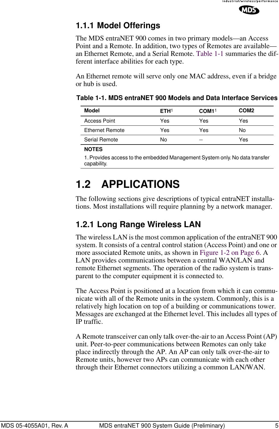
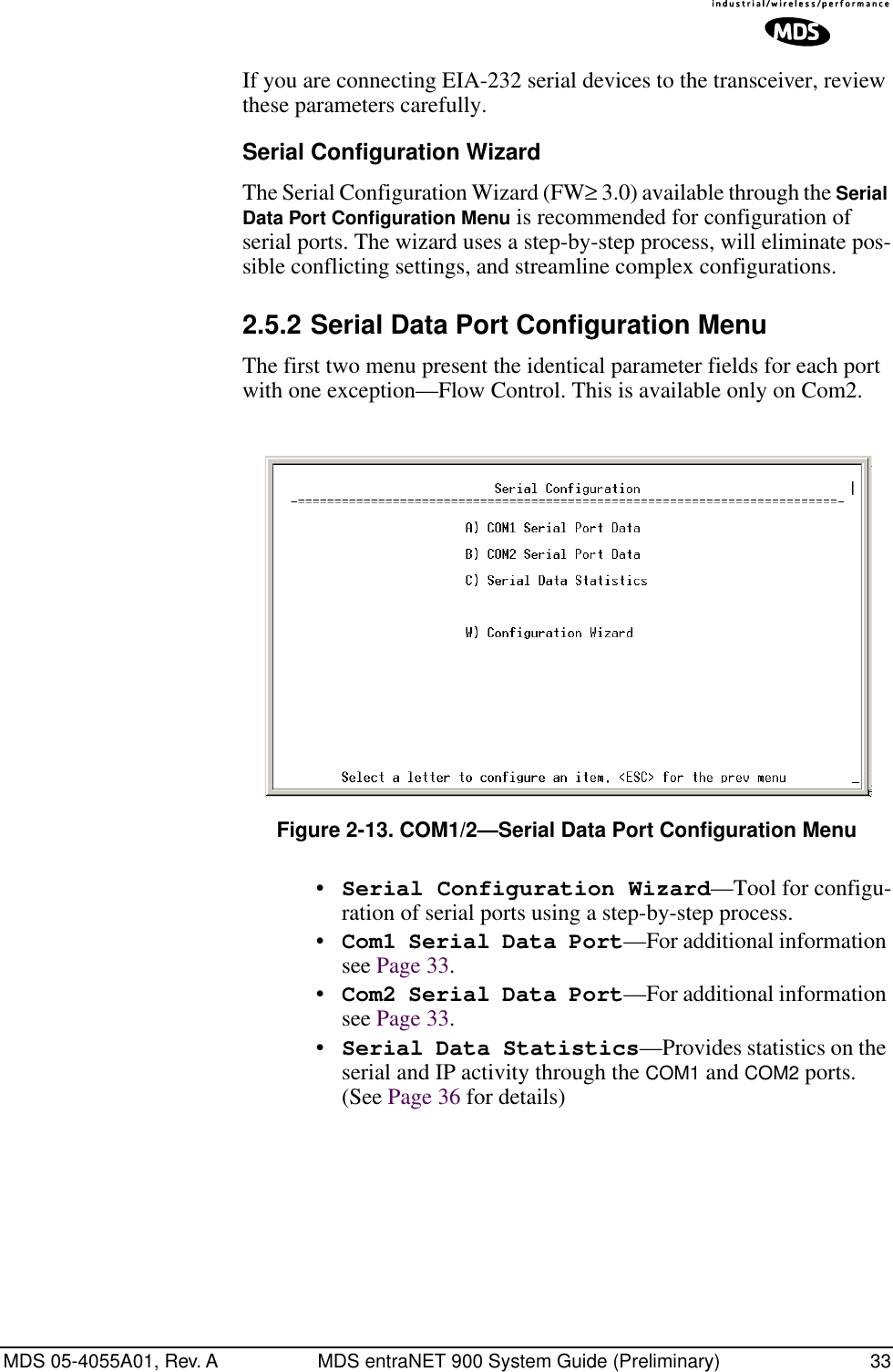
![MDS 05-4055A01, Rev. A MDS entraNET 900 System Guide (Preliminary) 1276.2.2 COM1 PortTo connect a PC to the transceiver’s COM1 port use a DB-9M to DB-9F cross-over cable. This cable may also be purchased from a computer retail store or mail-order company. For custom interface cables, use the pinout information in Figure 6-2 and Table 6-2.Figure 6-2. COM1 Port (DCE)(Viewed from the outside of the unit.) 6.2.3 COM2 PortFigure 6-3. COM2 Port (DTE)Viewed from the outside of the radioTable 6-2. COM1 Port Pinout, DB-9F/RS-232 InterfacePin Functions DCE1 Unused2 Receive Data (RXD) <—[ Out3 Transmit Data (TXD) —>[ In4 Unused5 Signal Ground (GND)6–9 UnusedTable 6-3. COM2 Port, DB-9M/EIA-232 InterfacePin Functions DTE1 Data Carrier Detect (DCD) In ]<—2 Receive Data (RXD) In ]<—3 Transmit Data (TXD) Out ]—>4 Data Terminal Ready (DTR) Out ]—>5 Signal Ground (GND)6 Data Set Ready (DSR) In ]<—7 Request-to-Send (RTS) Out ]—>8 Clear-to-Send (CTS) In ]<—9 Unused15965169](https://usermanual.wiki/GE-MDS/DS-ENET900ER.MANUAL/User-Guide-337074-Page-135.png)