GE MDS DS-LEDR700S Digital Radio User Manual 3627D LEDR Body
GE MDS LLC Digital Radio 3627D LEDR Body
UserManual.wiki
>
GE MDS
>
DS LEDR700S User Manual
Users Manual
Navigation menu
Upload a User Manual
Namespaces
Wiki Guide
HTML
PDF
Info
Views
User Manual
Discussion / Help
Navigation

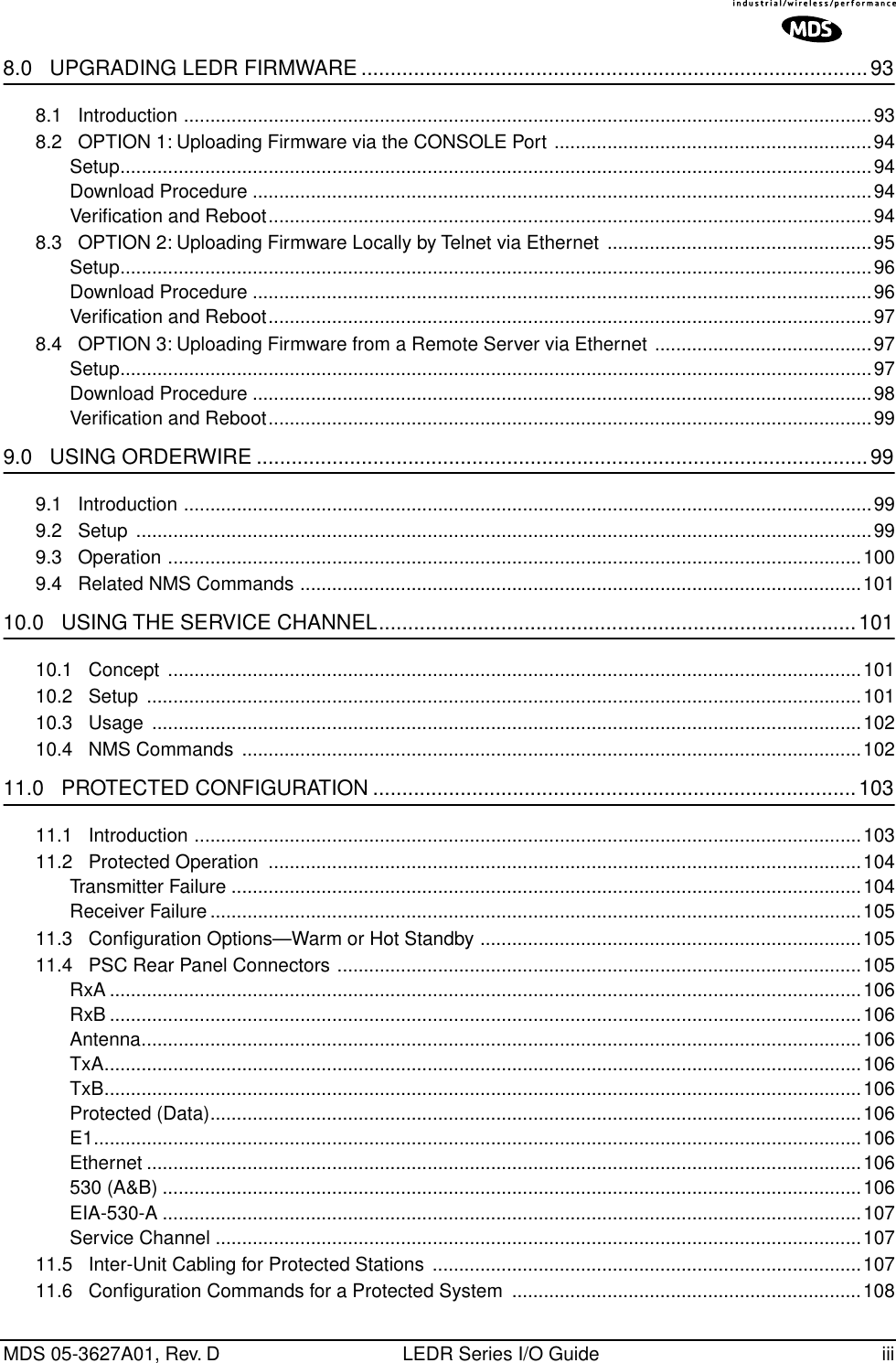
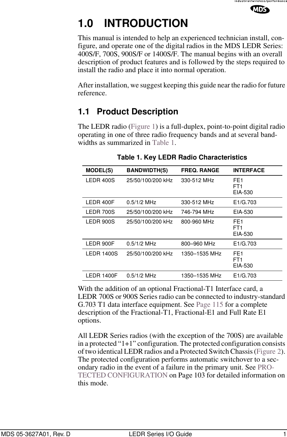
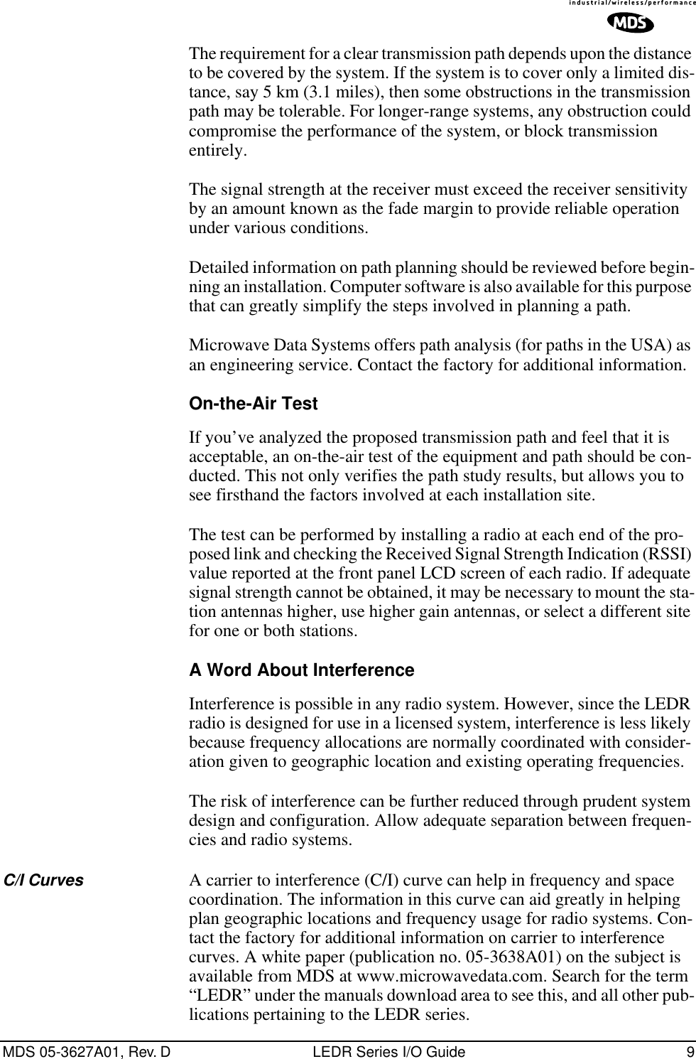
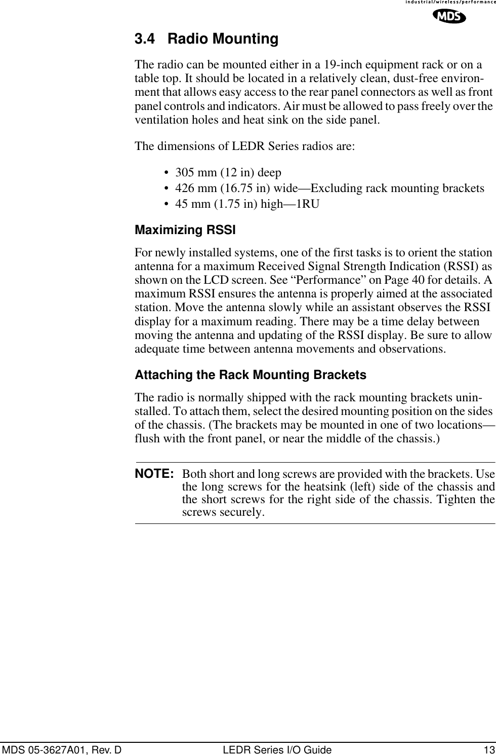
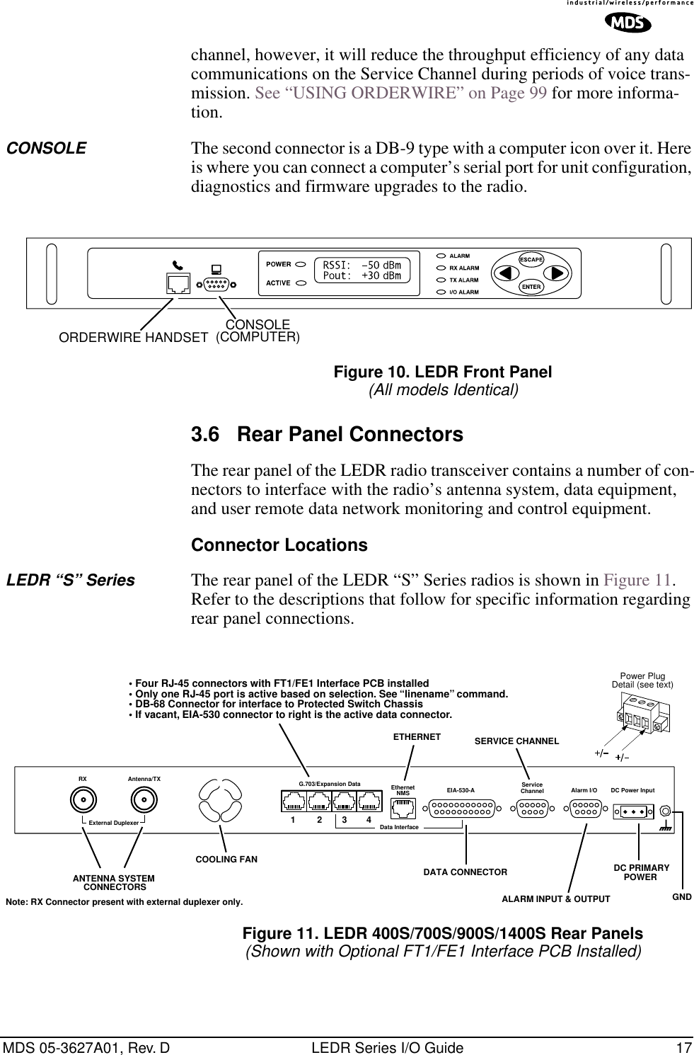
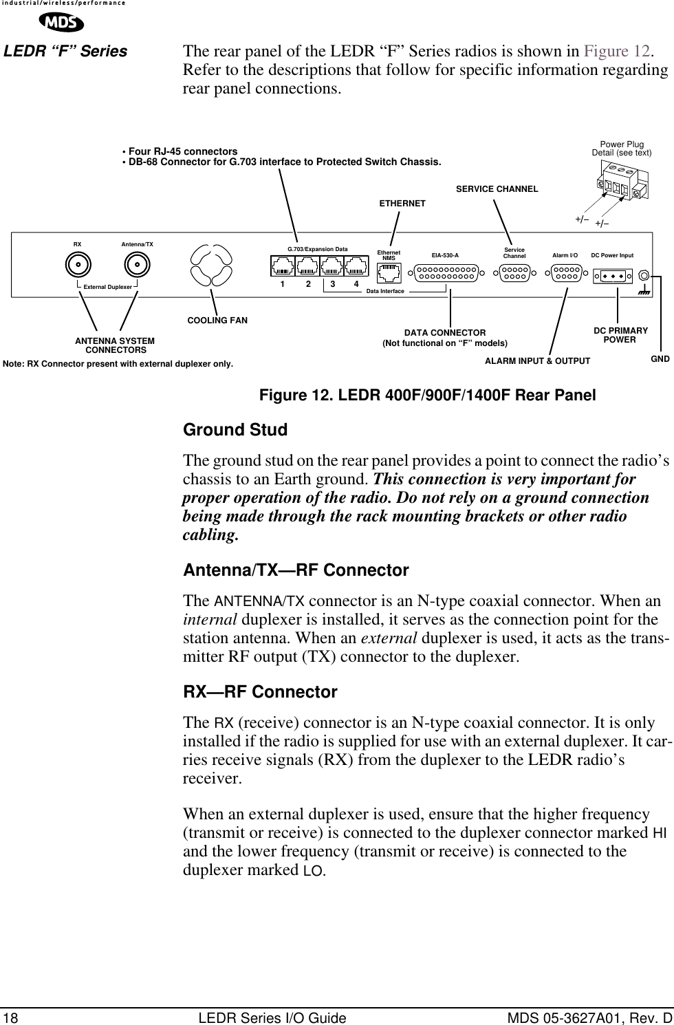
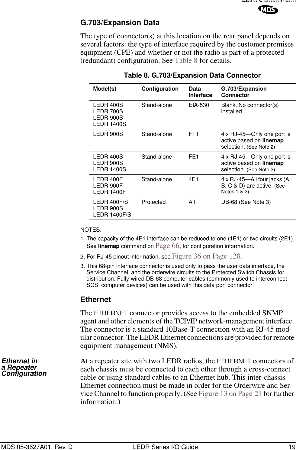
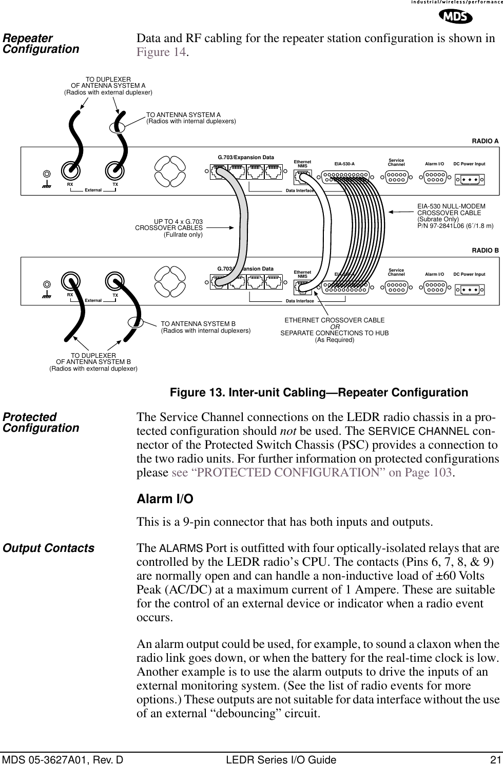
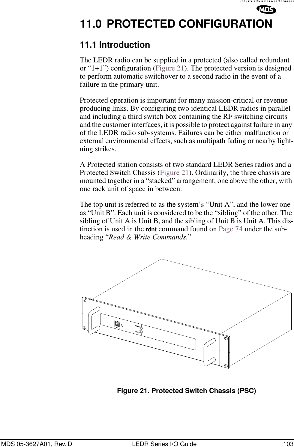
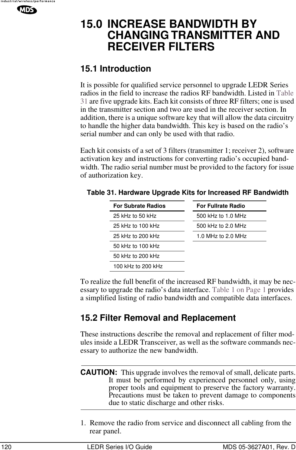
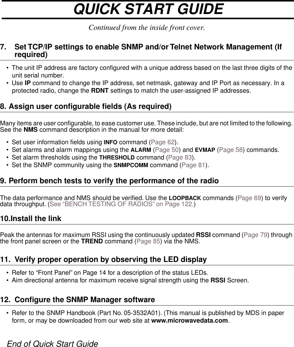
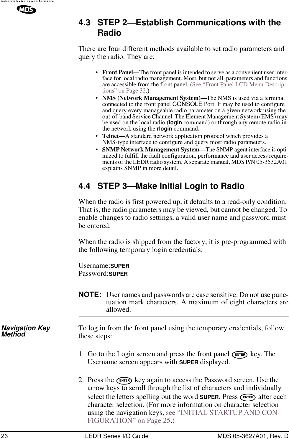
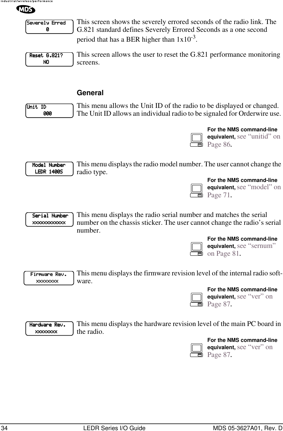
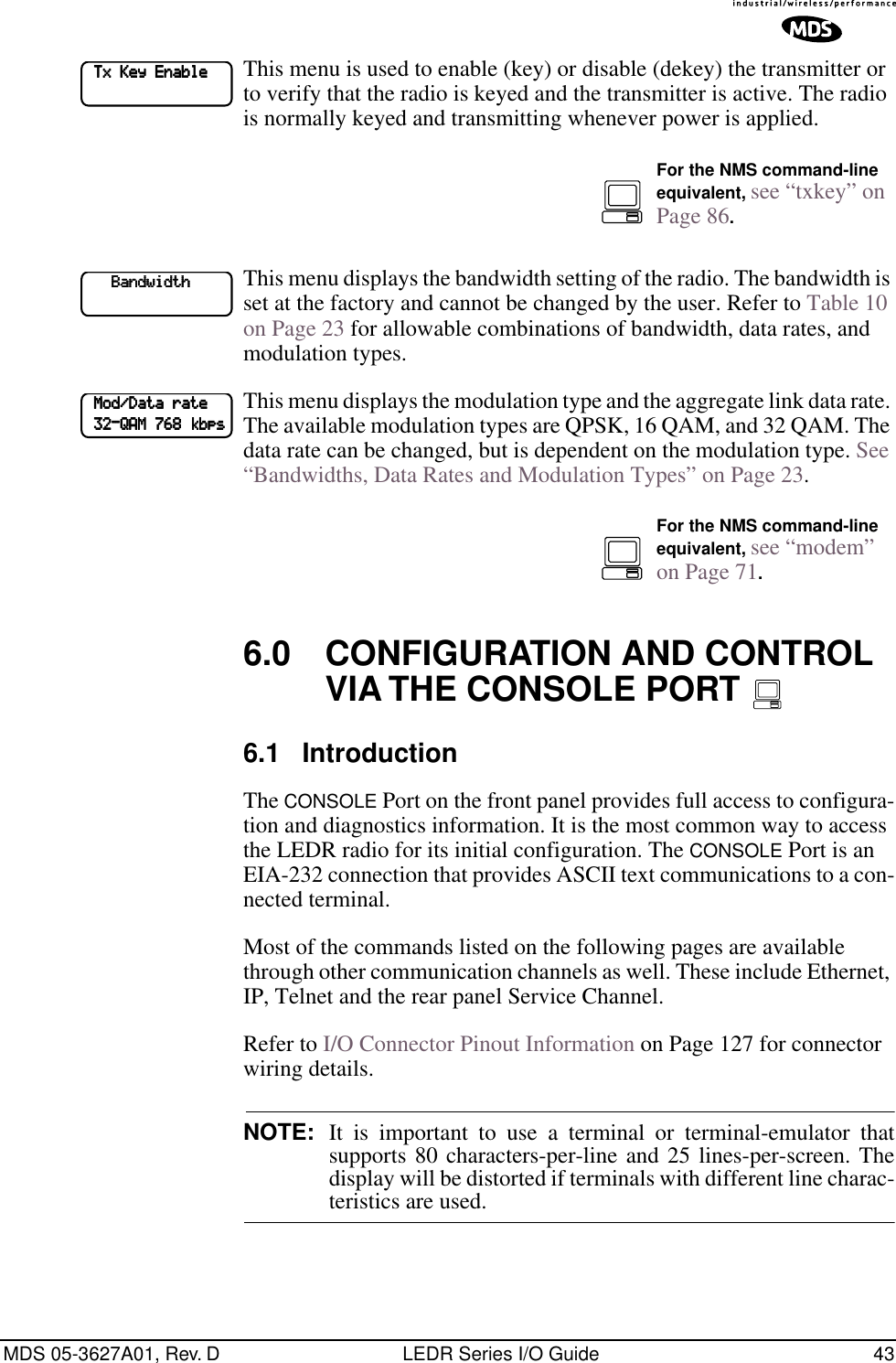
![MDS 05-3627A01, Rev. D LEDR Series I/O Guide 23Protected Configuration ConnectionsThere are several connections between the LEDR radio chassis and the Protected Switch Chassis. They include the primary data interface, RF, Ethernet, orderwire and Service Channel. Details on cabling and other items relating to the protected (redundant) configuration appear in PRO-TECTED CONFIGURATION on Page 103.3.7 Bandwidths, Data Rates and Modulation TypesThe hardware in the LEDR chassis is configured at the factory for a spe-cific bandwidth. However, the modulation type and data rate can be changed as long as the bandwidth is sufficient to support the modulation type and data rate. (If you need to change your radio’s bandwidth, please see “INCREASE BANDWIDTH BY CHANGING TRANS-MITTER AND RECEIVER FILTERS” on Page 120 for details.)Use of the modem command (Page 71) and configuration ([argument]) code automatically sets the combination of data rate, bandwidth and modulation type if the radio is capable of supporting itTable 10 shows the combinations of radio bandwidth, data rates and modulation types that are available for subrate radios at the time of pub-lication. Table 11 shows the combinations available for fullrate radios. Table 10. Subrate Bandwidth vs. Modem Selection Code Radio Bandwidth Configuration Code Data Rate(s) Modulation25 kHz B1 64 kbps 16-QAMC1 64 kbps 32-QAM50 kHz A1 64 kbps QPSKB2 128 kbps 16-QAM100 kHz A1 64 kbps QPSKA2 128 kbps QPSKB3 256 kbps 16-QAM200 kHz A1 64 kbps QPSKA2 128 kbps QPSKB3 256 kbps 16-QAMB4 384 kbps 16-QAMB5 512 kbps 16-QAMC6 768 kbps 32-QAM](https://usermanual.wiki/GE-MDS/DS-LEDR700S/User-Guide-312318-Page-31.png)
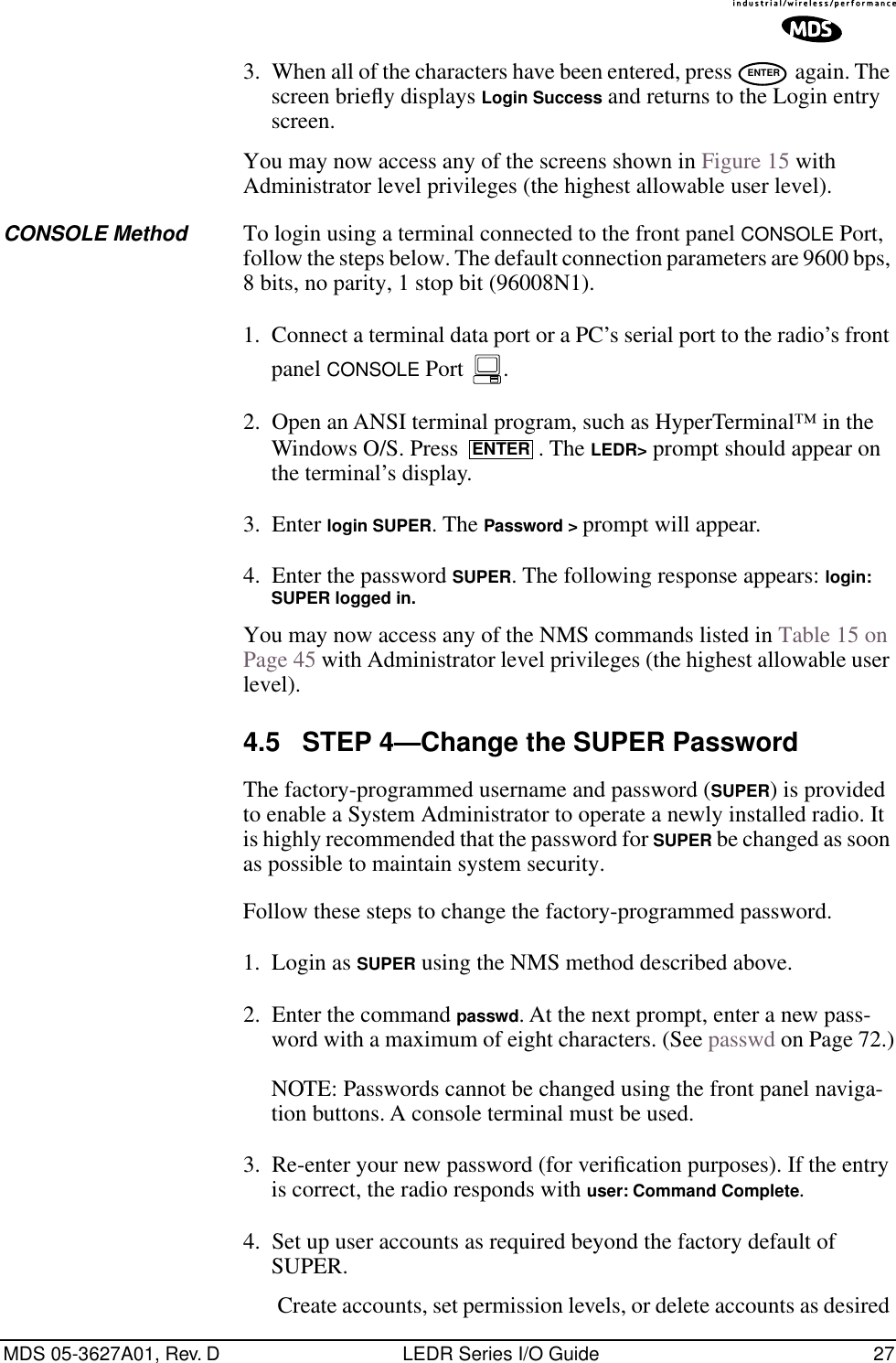
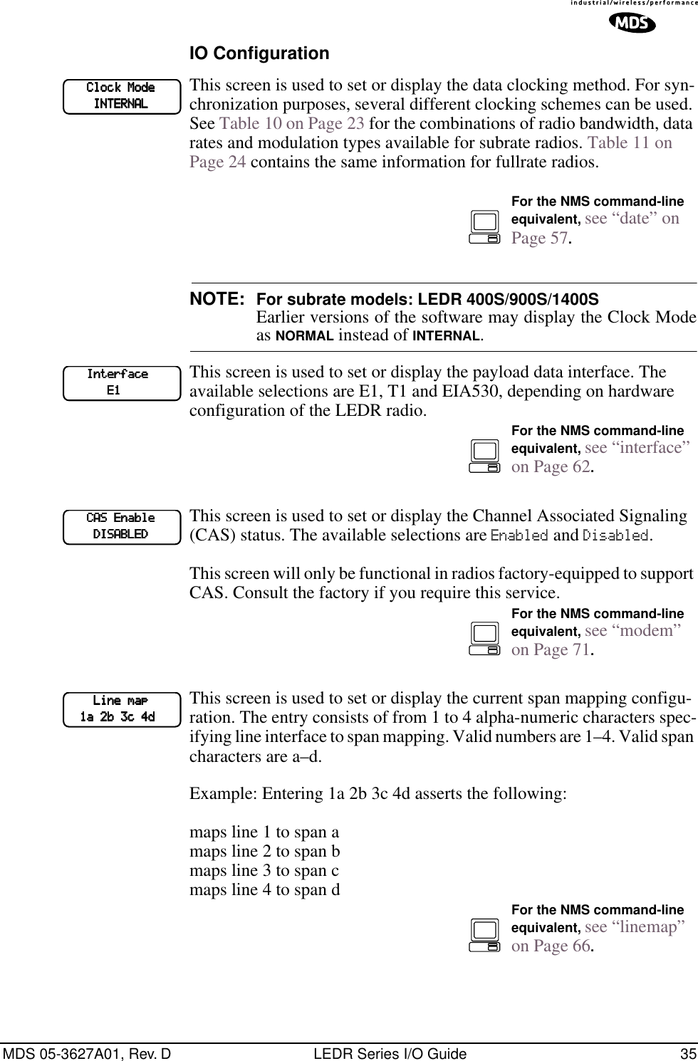

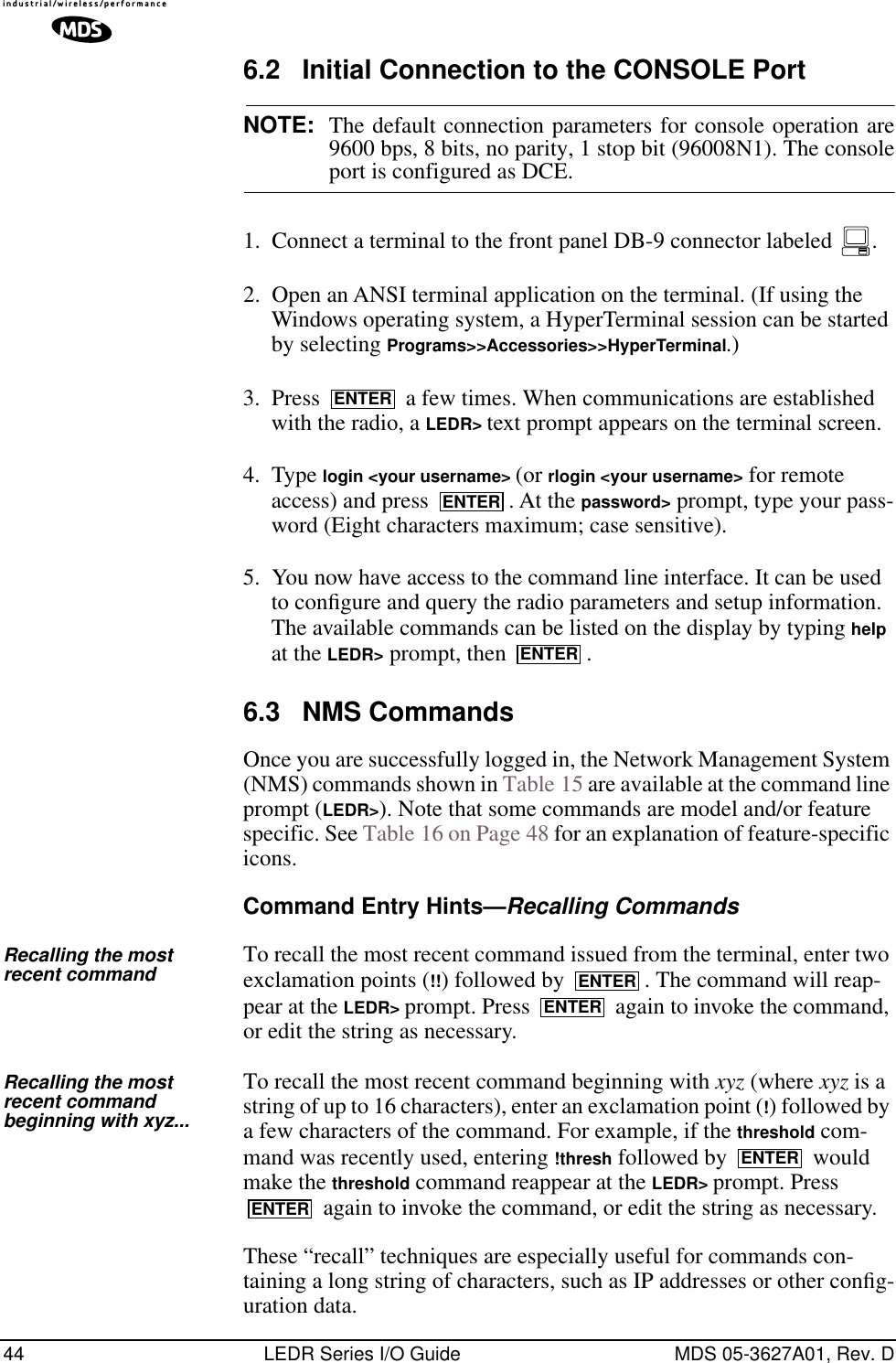
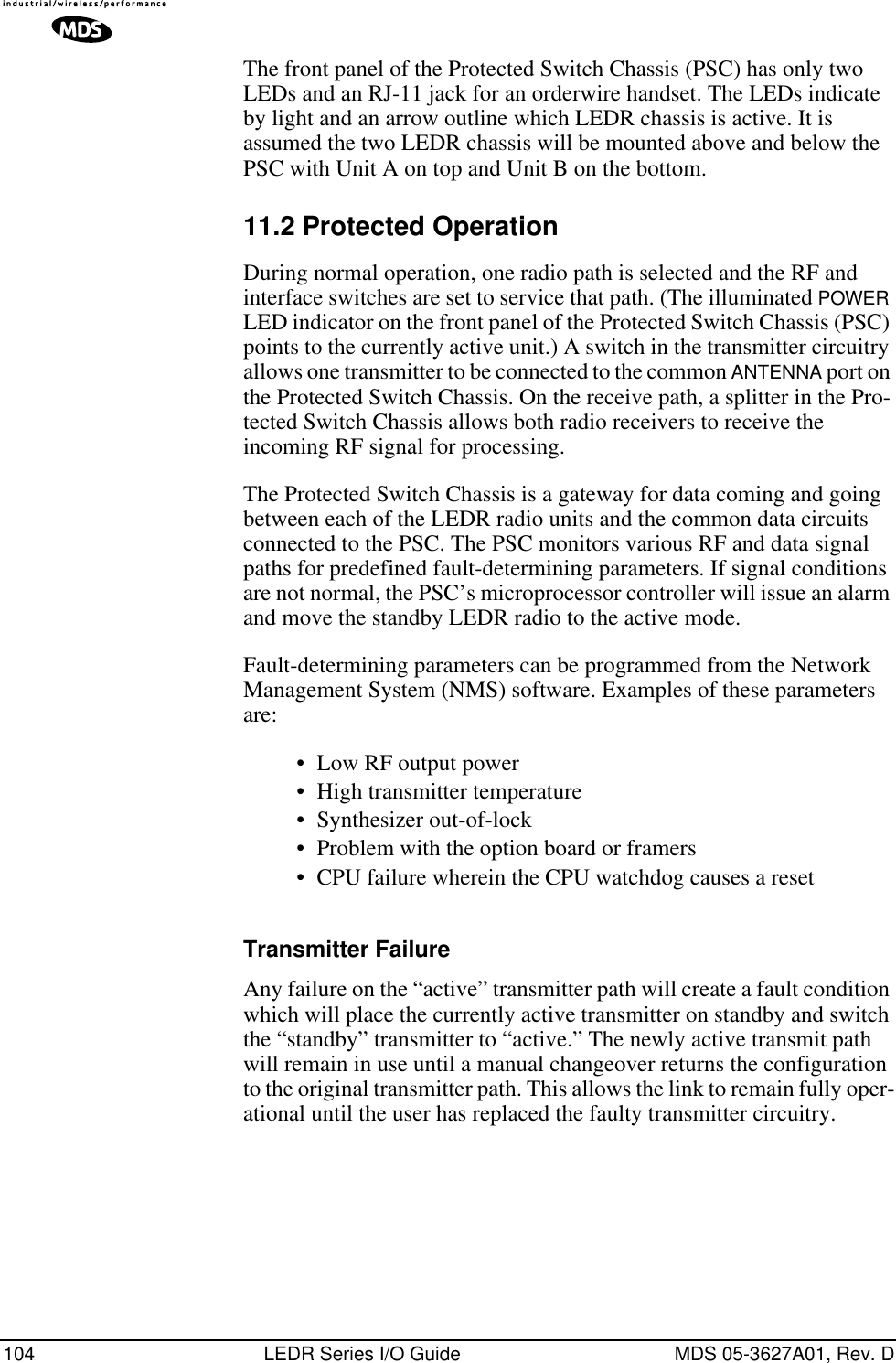
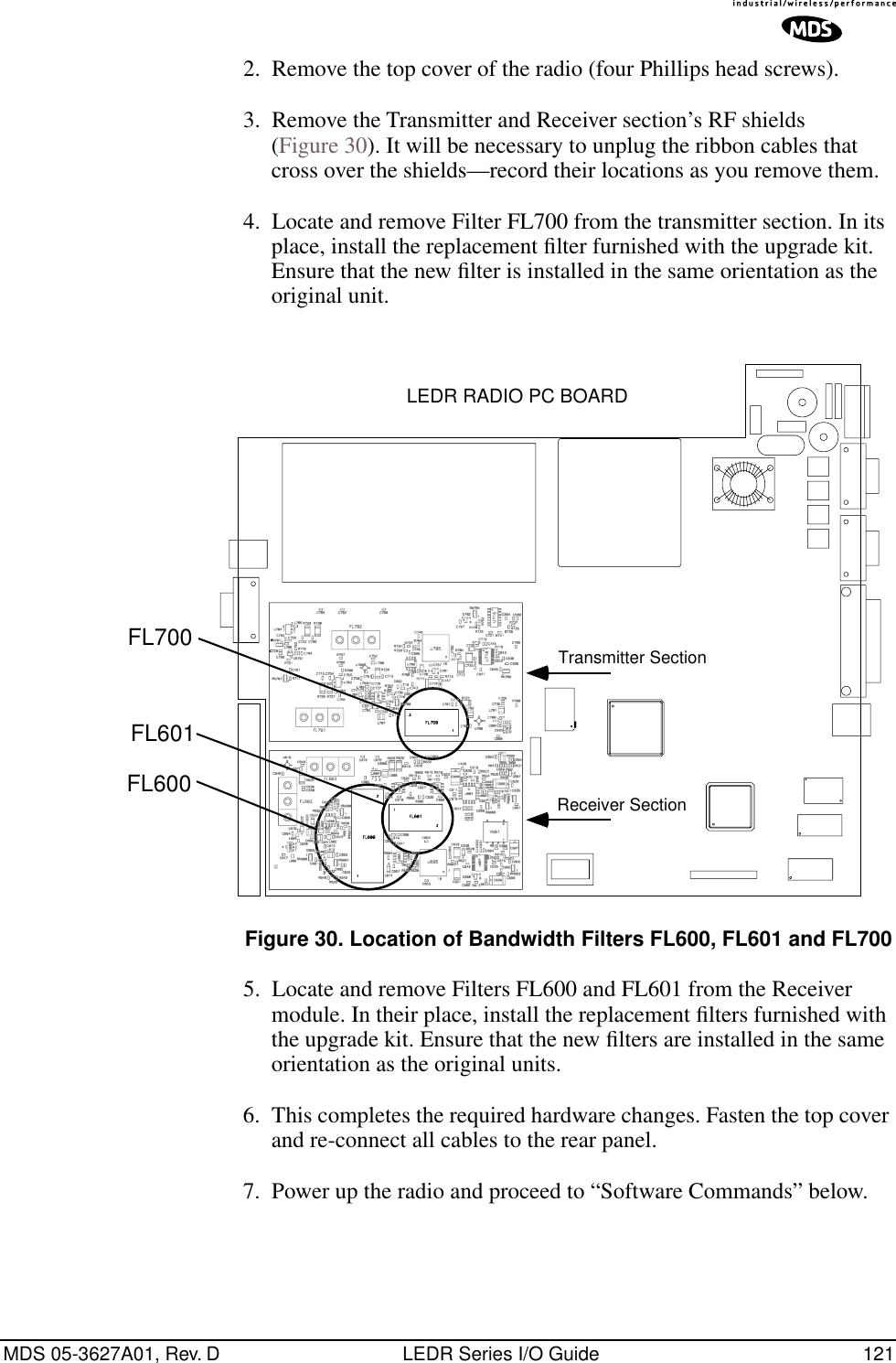
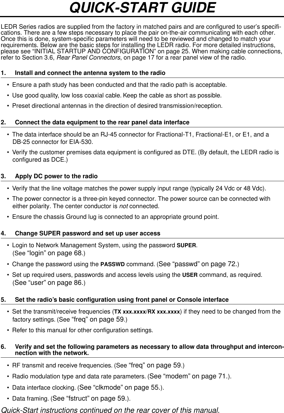
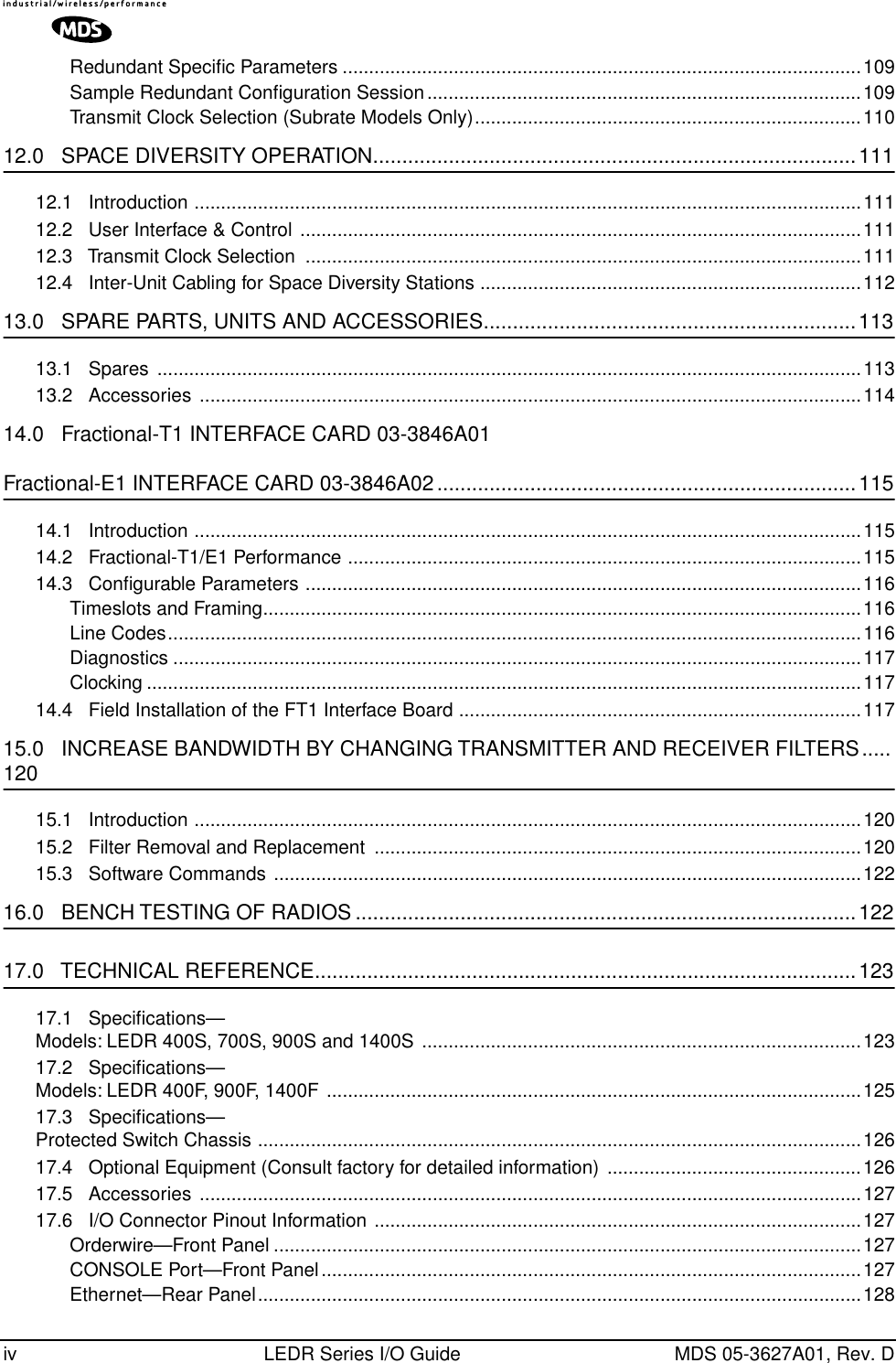
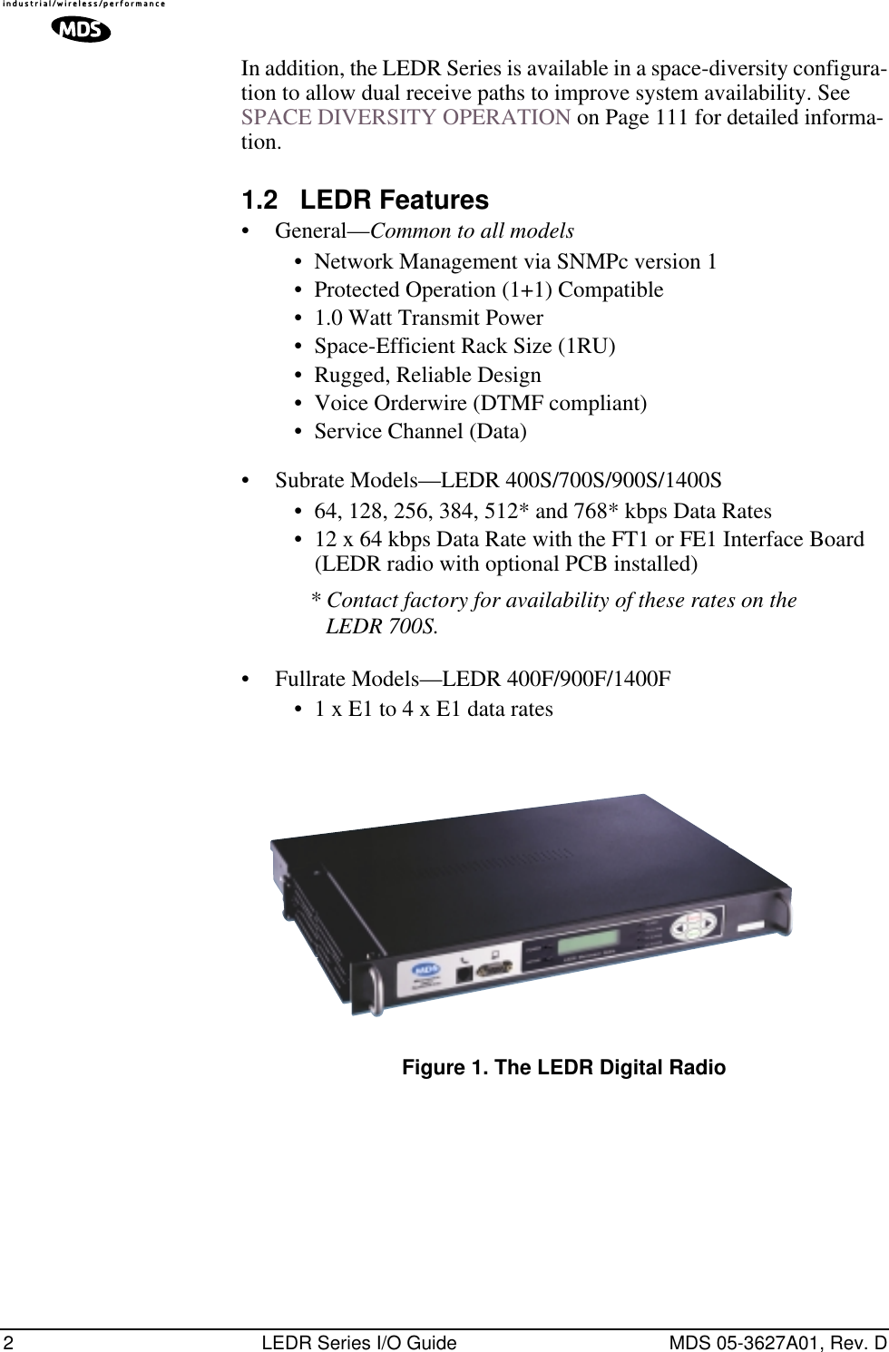
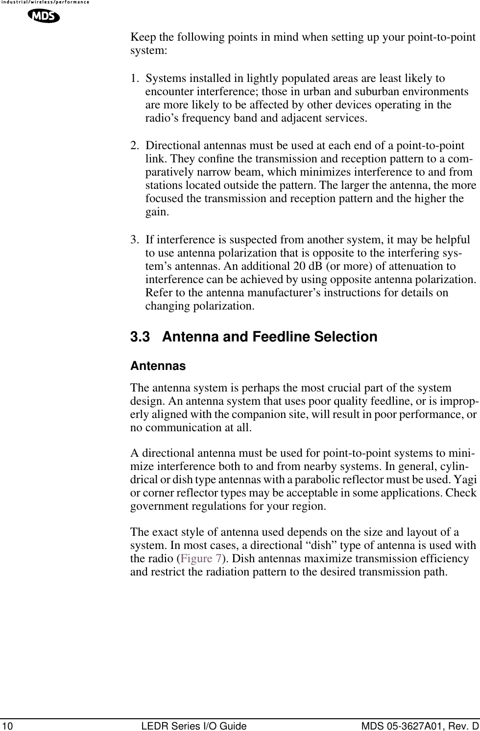
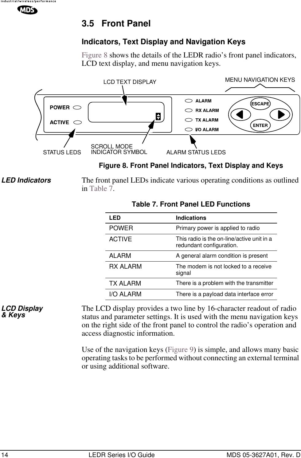
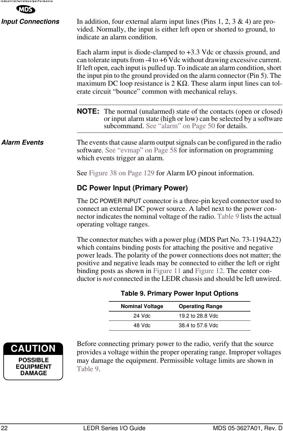
![48 LEDR Series I/O Guide MDS 05-3627A01, Rev. D6.4 Command Detailed DescriptionsIntroductionThe following commands are available through the CONSOLE port. These commands all require the Enter or Return key be pressed after the command. The following conventions are used to help describe the usage of the commands. Square brackets [ ] contain subcommands that may or may not be needed as part of the desired command. If there is more than one possible subcommand a vertical line | separates the commands within the square brackets. A subcommand is an optional exten-sion of the command and changes the basic command. Angle brackets <> contain arguments. The arguments are values needed to carry out the command such as a frequency value or option. Some commands are limited to use in certain radio models or configu-rations. These include subrate and fullrate. One or more of the symbols as listed in Table 16 will identify these commands.? or help User helpUsage: ? or helpThis command returns a list of currently available commands. In addi-tion, entering ? as a subcommand before or after a command returns usage information regarding the command.Command Example: ?rssi Returns: Usage: command [subcommand] <argument> Table 16. Feature-Specific IconsSymbol Interface/GroupEIA-530Fractional-T1/G.703Fractional-E1/G.703E1/G.703530FT1FE1E1ENTER](https://usermanual.wiki/GE-MDS/DS-LEDR700S/User-Guide-312318-Page-56.png)
![MDS 05-3627A01, Rev. D LEDR Series I/O Guide 49ais Alarm Indication Signal Usage: ais [linelist] [-g <on|off>] [-f <on|off>]This command enables or disables alarm signal generation [-g] and for-warding [-f] on specified E1/T1 interface lines. When generation is enabled, fault conditions within the link or at the line interface will cause the appropriate AIS/RAI signaling to occur. When forwarding is enabled, AIS/RAI signaling at the line interfaces will be detected and passed to the other end of the link.Command Example: ais -f on -g onReturns: AIS on RAI onNOTE: For protected configurations and full-rate radios, disable thealarm generation through the use of the ais -g off command.Background on AIS command:In fractional operation, the radio extracts the required timeslots and data at the input to a link, and reconstructs the full frame at the output end. The AIS -g (generation)> command, when enabled, allows the radio to override the frame reconstruction process in order to generate a proper all-ones alarm signal. For example, modem loss of synchronization will cause all-ones to be transmitted from the active G.703 ports. When AIS -g is disabled, the output will consist of a framed signal with all-ones in the active timeslots. In Fractional operation, AIS generation also creates a yellow alarm/RAI back to the defective source when a problem is found at the input. In FE1 mode, when AIS -g is enabled, loss of Multi-Framing Alignment Sequence (MFAS) at the line receiver will generate a Multi-frame Yellow Alarm (MYEL) or Multi-frame Remote Alarm Indication (MRAI) at the line transmitter.AIS <-f (forwarding)> is the act of detecting a condition at the input and causing an appropriate response at the other end. For example, with for-warding enabled, an all-ones signal applied at one end causes all-ones to be output at the other. A Remote Alarm Indication (RAI) applied will likewise appear at the opposite end. Disabling the forwarding function limits the presentation of alarm signaling to the active timeslots at the remote end. It is recommended that the ais -f on or ais --g on command be used for Fractional operation, to enable alarm generation and for-warding.In full-rate modes, the radio will always output AIS when the unit is unlocked—received radio signal is lost. When the modem is locked, and the input is removed from one end, you will get all-zeros at the other end unless AIS generation is enabled. Yellow alarms/RAI are not generated E1FT1FE1](https://usermanual.wiki/GE-MDS/DS-LEDR700S/User-Guide-312318-Page-57.png)
![50 LEDR Series I/O Guide MDS 05-3627A01, Rev. Din the full-rate LEDR radio models; however AIS and RAI forwarding are available. It may be desirable to have alarms generated (ais -g on) in full rate models, depending on the user's requirements as outlined in the next paragraph.Since the generation and forwarding operations require use of the Ser-vice Channel, the AIS/RAI response times are on the order of a few sec-onds. Generation and forwarding can be very helpful in correcting problems with the network when they arise. However, in systems where the response time is critical, these modes should be disabled: In frac-tional mode, enter ais -f off -g off. In full-rate mode, enter ais -g off.alarm Alarm I/OUsage: alarm [in|out] [1-4|all] [subcommand] [arguments]This command is used to control the four (4) external alarm contacts and display the state of the four (4) external alarm inputs.Outputs (Relays)—Alarm outputs may be directly driven to a state, or be mapped to, internal events via the evmap command (Page 58). When mapped to events, the active level may repro-grammed to be either active-open or active-closed. Active means that an event is mapped to an external alarm output that is currently active. (See “Alarm I/O” on Page 21 for electrical parameters and typical examples of alarm usage.)Inputs—Alarm inputs are used to generate events in the event log and also generate SNMP traps if so programmed by the events filter command. They may be directly read via the alarm command, as well. They may also have their active level set to be either active high or low. (alarm active high; alarm active low) Naming—Finally, both inputs and outputs may be named by users to allow for easy identification. For example, “Fire Alarm” could be used as the name for Alarm Input 1. Traps are sent with this name so that users may more easily identify the source of the alarm.Subcommands: active [open|closed]—Set alarm input/outputs active state. set [open|closed] —Latch alarm outputs to one state to ignore events which are assigned to them. name [name_string]—Create a user defined “name” for each alarm. No spaces, 16 characters maximum; not compatible with “all”.Command Example #1:alarm in all](https://usermanual.wiki/GE-MDS/DS-LEDR700S/User-Guide-312318-Page-58.png)
![MDS 05-3627A01, Rev. D LEDR Series I/O Guide 51Returns: alarm: Active Currentalarm: Type # Name Level Readingalarm: ====== = ================ ====== =======alarm: Input 1 AlarmInput1 closed openalarm: Input 2 AlarmInput2 closed openalarm: Input 3 AlarmInput3 closed openalarm: Input 4 AlarmInput4 closed open Command Example #2:alarm out 2 set closed Returns: alarm: Active Currentalarm: Type # Name Level Readingalarm: ====== = ================ ====== =======alarm: Output 2 AlarmOutput2 closed closedCommand Example #3: alarm in 3 Returns: alarm: Active Currentalarm: Type # Name Level Readingalarm: ====== = ================ ====== =======alarm: Input 3 AlarmInput3 closed openalert Alert another LEDR Radio in the NetworkUsage: alert <3 digit unit ID>|allThis command is used to sound the alert buzzer on another radio. This function allows you to signal a radio and alert someone that the Order-wire handset should be picked up.The three-digit number following the command indicates the unit ID of the radio that will be signaled. Radios available for signaling can be determined by issuing the network command. See “USING ORDER-WIRE” on Page 99 for more information.arp Address Resolution Protocol (ARP) Setting of Ethernet PortUsage: arp [-a | -s [ip address] | -d [ip address]-a View the ARP table-s Add the IP address to the ARP table. The radio will proxy ARP for any addresses that are added-d delete the IP address from the ARP tableThis command displays the contents of the radio’s ARP table, which is a listing of IP addresses of which the radio is aware. It can also be con-figured to “spoof,” or proxy, for other (non-LEDR) devices that are managed using the radio’s out-of-band Service Channel and directly](https://usermanual.wiki/GE-MDS/DS-LEDR700S/User-Guide-312318-Page-59.png)
![52 LEDR Series I/O Guide MDS 05-3627A01, Rev. Dconnected at some point to a radio’s Ethernet port, or to a common hub with a LEDR radio. In other words, the radio network can be configured for seamless integration of other IP-manageable devices by responding to ARP requests and/forwarding IP traffic directed to those devices. See the route command on Page 77 for information on other necessary configuration steps to allow for IP connectivity to LEDR radios and associated devices using the radio’s network-management channel.ber Bit-Error Rate of the RF LinkUsage: berThis command displays pre-FEC and post-FEC Bit-Error Rate (BER) between the LEDR radios in the first link.NOTE: The BER measurement limit is 1E-8. For more reliable infor-mation on the link-error rate, use the g821 demod command. bert Bit-Error Rate Test of Data Interface Usage: bert [linelist] [-e [pattern] | -d | -i [error] | -lp | -le | stats]bert is used for diagnostic purposes by causing the selected line of the FT1/E1 interface port lines to output a user-selectable pseudo-random bit sequence, either framed or unframed. This command also allows the user to measure the bit error rate, number of errors, etc. This command tests all T1/E1 timeslots without regard to the timeslot command’s con-figuration.linelist—List of local line interfaces. Can be single line number or line-name (see linename command), comma-separated list of line numbers or linenames, a range of line numbers (for example: 1-4), or if linelist is not given, all lines will be tested.NOTE: The hyphen is part of the argument string and must be included for the command to function.Subcommands:Control—-e Enable bert generation/monitoring for line(s)Can be immediately followed by the test pattern index value (See -lp below). If none is included in the command, the last-used pattern will be implemented.-d Disable bert generation/monitoring for line(s)-i Inject error. Index specifying type of error to inject. If no error is specified, last error selected is used.E1FT1FE1](https://usermanual.wiki/GE-MDS/DS-LEDR700S/User-Guide-312318-Page-60.png)
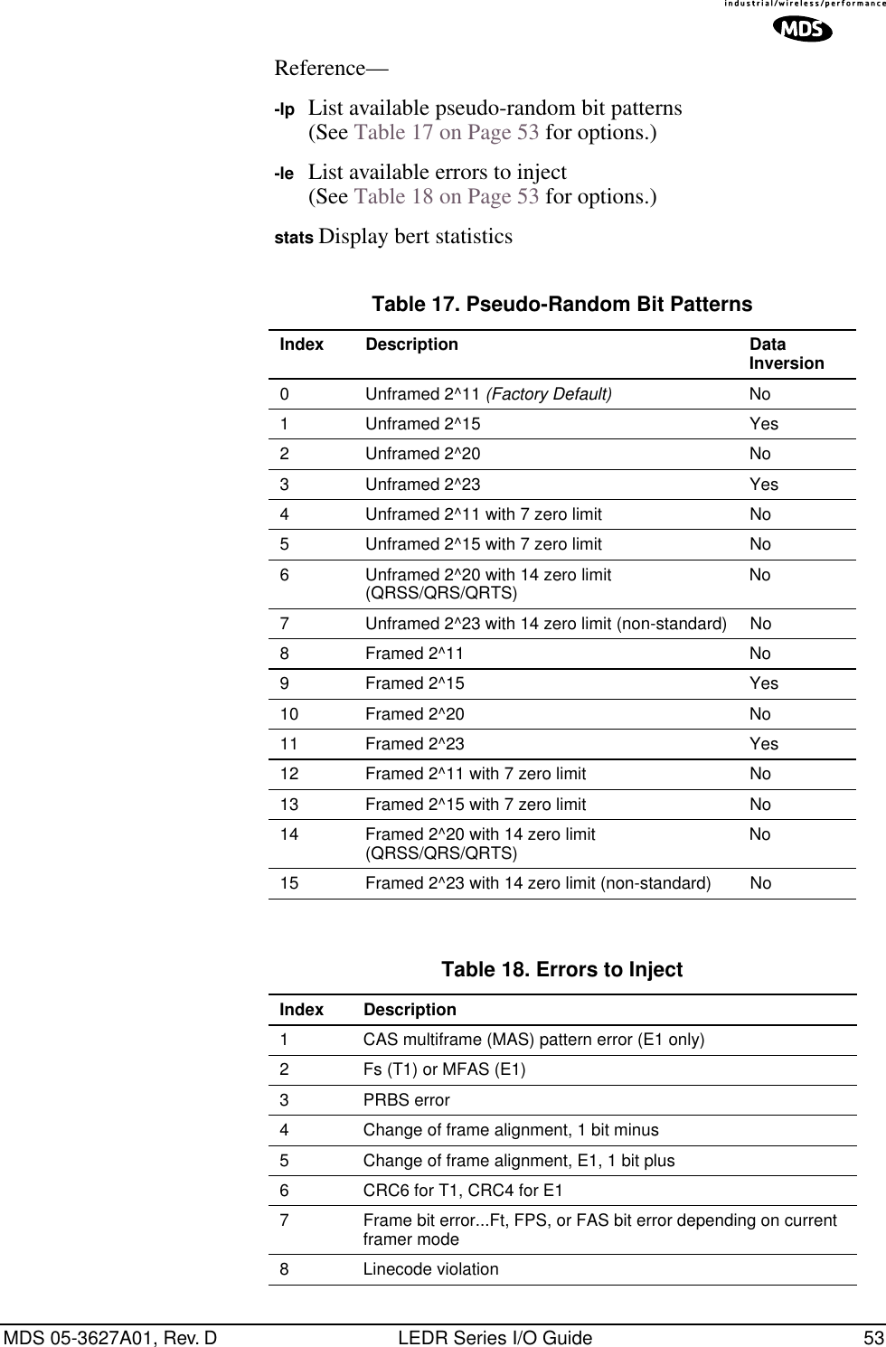
![54 LEDR Series I/O Guide MDS 05-3627A01, Rev. DBackground information on bert command:The bit error-rate test command, bert, is used to evaluate the link between the LEDR data interface and the customer premises equipment (CPE). When used, the LEDR radio will send a test pattern out of the LEDR FT1/E1 Data Interface lines towards the CPE while simulta-neously attempting to receive the same pattern back from the CPE. For example, you can loopback the CPE’s external data device’s I/O, then issue a bert command to the LEDR radio to check the integrity of the wire connection. The test pattern can be user-selectable. (See bert com-mand Options above for further information.)NOTE: The bert command will not test or evaluate the integrity of theLEDR radio link. (See “BENCH TESTING OF RADIOS” onPage 122 for further information.)NOTE: When operating FT1 or FE1 interfaces, this command tests allT1/E1 timeslots without regard to the timeslot command’sconfiguration.boot Boot from Active/Archive SoftwareUsage: boot [<1|2|-s|-o>]This command is used to view or change the radio’s active software image. If boot is entered alone, the currently active firmware image (1 or 2) is displayed. A selection of 1 or 2 after the command (e.g., boot 2) ini-tiates a reboot from that image. (A message appears to confirm that you wish to reboot the radio firmware.) Upon reboot, the radio and all radio functions are restarted in a manner similar to turning the radio power off and then on again. The radio is taken out of service until it re-initializes, and the link loses synchronization until the reboot process completes and the demodulators at both ends reacquire the radio signals.A choice of software images allows booting an alternate version of radio software. The ability to have two radio-resident software images allows radio software reprogramming over-the-air and the ability to restore operation to the original software if required.Subcommands:1Boot from Image 12Boot from Image 2-s Boot from the active (same) image-o Boot from the inactive (other) imagebuzzer BuzzerUsage: buzzer](https://usermanual.wiki/GE-MDS/DS-LEDR700S/User-Guide-312318-Page-62.png)
![MDS 05-3627A01, Rev. D LEDR Series I/O Guide 55This command briefly sounds the radio’s piezo buzzer for testing. It should be used only from the CONSOLE Port.Example Response:buzzer: Starting testbuzzer: Test completeclkmode Clock Mode (Subrate Radios Only)Usage: clkmode [<internal|exttx|looped|extdce>] This command displays or sets the source of the radio’s transmit clock. For synchronization purposes, several different clocking schemes can be used. See Table 10 on Page 23 for the combinations of radio band-width, data rates and modulation types that are available for subrate radios. Table 11 on Page 24 shows the combinations available for full rate radios.Subcommands:internal—Internal oscillator sources TC; RC derived from far end of radio link (default).exttx—ETC accepted from external equipment on EIA-530 inter-face; RC derived from far end of radio link.looped—Recovered RF (RX) clock; TC is synchronized to RC; RC is derived from far end of radio link. Note: Do not use looped clocks at both ends of any radio link.extdce—ETC and ERC are accepted as inputs on the EIA-530 interface.NOTE: Earlier versions of the software may display the Clock Modeas NORMAL instead of INTERNAL. Firmware Version 2.4.0 and Later – Use the clkmode command to determine which port has been selected to drive the timing at the inter-face.Firmware Version 2.3.1 and Earlier – This command allows the var-ious possible clock sources to be prioritized. As timing sources become available, the highest-priority source will be chosen by the system. If attaching to the network or equipment that provides timing, a universal form of the command would be clkmode 1 2 3 4 internal. If attaching to equipment that will provide looped-back timing, a universal form of the command would be clkmode remote internal. If both ends of the link pro-vide looped timing, the internal clock source should be selected at one end by entering clkmode internal. Note that at least one end of the link should have either network or internal timing selected.530E1FT1](https://usermanual.wiki/GE-MDS/DS-LEDR700S/User-Guide-312318-Page-63.png)
![56 LEDR Series I/O Guide MDS 05-3627A01, Rev. DNOTE: Firmware versions 2.3.1 and earlier, require that this parameter be properly configured for correct operation of the link. More recent firmware versions do not require that this item be manually configured. However, the clkmode command may still be used to determine which port is being used to drive the timing.Firmware Version 3.0.0 and Later– The clkmode command applies only to the EIA-530 interface.coffset Carrier Offset of Radio ModemUsage: coffsetThis command displays the Modem Carrier Frequency Offset.con Console port configuration on LEDR front panelUsage: con (baud [300|1200|2400|4800|9600|19200|38400|115200]) (parity [none|even|odd])This command sets or displays the CONSOLE Port’s operating parame-ters. The CONSOLE Port data rate is set or displayed using the baud sub-command. The parity is set or displayed using the parity subcommand.The default setting is 9600 bps, no parity, 8 data bits and 1 stop bit.config ConfigurationUsage: config [get|send|getall] [filename|console] [hostIP]This command is used to get or send a radio configuration file.The radio stores its configuration data in a file that you can download using the config send command. The output can be directed to a file or to the NMS window, either in a Telnet session or a serial NMS session. The config send command allows sending the configuration file over the Ethernet management channel and storing it on a PC running a TFTP server.Subcommands:send—Upload entire radio configuration file to host (includes all radio-specific data)get—Download radio configuration file from host (DOES NOT download radio-specific data)getall—Download entire radio configuration file from host (including all radio-specific data)Radio-specific data includes IP address, network settings, frequencies, target power thresholds, calibration data, and IP routing table.Command Example: config send config.txt 192.168.1.14](https://usermanual.wiki/GE-MDS/DS-LEDR700S/User-Guide-312318-Page-64.png)
![MDS 05-3627A01, Rev. D LEDR Series I/O Guide 57This sends the configuration file to a TFTP server running on host 192.168.1.14 and stores it as a file called config.txt.date DateUsage: date [MM/DD/YYYY]This command sets or displays the date and time of the radio’s internal real-time clock. The real time clock operates from an internal lithium battery so it is running even if the radio has no DC power connected. The date format may also be set or displayed from this screen for one of three formats: U.S., European, or generic.The real time clock is fully compliant with year 2000 standards.Subcommands: date format [<1-3>] Date Format 1: mm/dd/yyyy (All numbers)Date Format 2: dd/mm/yyyy (All numbers)Date Format 3: dd-MON-yyyy (English abbreviation of month)Example Response: date: 07-JUN-1999 08:11:30dtmf Dual Tone, Multi-Function tone selectionUsage: dtmf [on|off]This command is used to turn the DTMF signaling feature on or off.eia530 EIA-530 selectionUsage: eia530 [rts <on|off>] [dtr <on|off>]This command is used to set or display the status of the EIA-530 control lines (RTS and DTR).ethernet Ethernet Port’s Hardware AddressUsage: ethernet This command displays the fixed hardware address of the radio’s Ethernet port. This address is globally unique; it is assigned at the fac-tory and cannot be changed.events EventsUsage: events [subcommand] [<arguments>]Subcommands: pendingfilter [event#] [count]initdesc [<event#>]530](https://usermanual.wiki/GE-MDS/DS-LEDR700S/User-Guide-312318-Page-65.png)
![58 LEDR Series I/O Guide MDS 05-3627A01, Rev. DThis command allows viewing the pending events (pending), sup-pressing the notification of particular events (filter), initializing events processing (init) and display of event descriptions (desc). To turn off log-ging (notification in the event log) for a particular event, the filter count value should be set to zero.Events 135-138 are remote alarm in [1-4], respectively, which reflects the event state of the alarm in [1-4] of the remote-located radio at the other end of the RF link.Example Response:events {events}: -DEMOD_ACQUISITION (Event #27)events: Event#0 Filter count=1events {init}: The event log has been re-initializedevents {desc}: Event#40 Description-IO2_DIG_REM_LPBACKevmap Event Mapping (for Alarm Output and LEDs)Usage: evmap [subcommand] [event #] [arguments]This command sets or displays which radio system events cause alarm indications on the front panel LEDs or the rear panel ALARM I/O con-nector. The user can rename the alarm events, but they cannot be deleted, nor can new ones be created.The subcommands specify which output will be asserted (led or aout) upon occurrence of an event #. Multiple outputs can be specified with spaces between them. The dump option allows determining the current event mapping for all of the events or, optionally, a specified numeric range of events.Events 135-138 are remote alarm in [1-4], respectively, which reflects the event state of the alarm in [1-4] of the remote-located radio at the other end of the RF link. Use the event filter counter to enable each particular event. Use evmap and map to alarm output contact when necessary.Subcommands are listed below:led [ioalarm|txalarm|rxalarm|alarm|none]—Maps front panel LED(s) to an event.aout [none|1|2|3|4]—Maps an alarm output(s) to an event.dump [<range>]—Display the LED and alarm output mappings for all events.See Figure 8 for reference to the Front Panel LEDs. Refer to Alarm—Rear Panel on Page 129 for the pinouts of the ALARM I/O connector and Disabling the Front Panel Alarm LED for Unused E1 Option Ports on Page 88 for further information.fec Forward Error Correction StatisticsUsage: [fec <clear>]](https://usermanual.wiki/GE-MDS/DS-LEDR700S/User-Guide-312318-Page-66.png)
![MDS 05-3627A01, Rev. D LEDR Series I/O Guide 59This command displays corrected bytes and uncorrectable FEC block errors.Example Response: fec: 1812992 Correctable Bytesfec: 2 Uncorrectable Blocksfreq Frequency of TX & RX ChannelUsage: freq [<tx|rx>] [<freq>] [<freq>]This command sets or displays the transmit and receive frequency.Example Response: freq {TxFreq}: 942175000 Hzfreq {RxFreq}: 944175000 Hzfset Frequency SettingUsage: fset [<min freq>] [<max freq>]This command sets the absolute frequency limits of the transmitter and receiver.Example Response: fset {Tx MinFreq}: 1350000000 Hzfset {Tx MaxFreq}: 1535000000 Hzfset {Rx MinFreq}: 1350000000 Hzfset {Rx MaxFreq}: 1535000000 Hzfstruct Frame Structure Usage: fstruct [linelist] [mode <0-7|none>]This command is used to set or display the span(s) frame structure. The [linelist] variable represents a list of line interfaces. This entry can be either a single line number or line name (see linename command), a comma-separated list of line numbers or line names, a range of line numbers (i.e., 1-4), or if linelist is not given all lines. In general, this parameter should be configured to match the frame structure used by the customer premises equipment. The fstruct com-mand also controls the generation of performance report messages in ESF modes. In E1 radios, an unframed mode is available by issuing the command fstruct mode 8.In Fractional-E1 mode timeslot 0 is always sent, and for fstruct modes 4 through 7, timeslot 16 must be added to the payload list for proper oper-ation.E1FT1FE1](https://usermanual.wiki/GE-MDS/DS-LEDR700S/User-Guide-312318-Page-67.png)
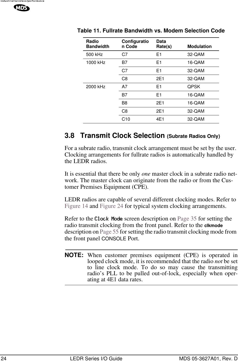
![60 LEDR Series I/O Guide MDS 05-3627A01, Rev. DTable 19 shows a list of line mode values for T1 interfaces and Table 20 for E1 interfaces. g821 G.821 Information Usage: demod io1|io2|io3|io4|all [clr]This command is used to show or reset the radio’s G.821 information. The LEDR family of radios support the ITU G.821 recommendation for display of four categories of statistical availability information: avail-able seconds, errored seconds, severely errored seconds, and unavail-able seconds. Example Response: Demodulator: ERROR FREESavail: 1036Sunavail: 0ES: 0SES: 0group Group Number in LEDR SystemUsage: Group [<0-99>]Table 19. T1 Frame’s Line Mode Values Value Mode0 FT only (default)1 ESF2 ESF + PRM3SF4 SF + JYEL5 ESF + CRC6 ESF + CRC +PRMTable 20. E1 Frame’s Line Mode Values Value Mode0 FAS only (default)1 FAS + BSLIP2 FAS + CRC3 FAS + CRC + BSLIP4 FAS + CAS5 FAS + CAS + BSLIP6 FAS + CRC + CAS7 FAS + CRC + CAS + BSLIP8 Raw, unframed, transparent mode.** Mode 8 is forbidden in fractional modes.E1FT1FE1](https://usermanual.wiki/GE-MDS/DS-LEDR700S/User-Guide-312318-Page-68.png)
![MDS 05-3627A01, Rev. D LEDR Series I/O Guide 61This command sets or displays the network group in which the radio is operating. Example Response:group: 1In a typical system, all the radios would operate in the same group, allowing the flow of network-management and orderwire activity between radios and from one radio link to any other in the system. At a repeater site, all radios must be set to the same “group number” (and not group zero) for this flow of information to take place. Setting group numbers differently in repeater systems isolates links from each other from a network-management perspective, allowing segmenting net-works and controlling the flow of network-management information. Across a radio link, groups can differ from each other; only radios phys-ically connected by Ethernet cables to each other or to the same hub must have the same group number to intercommunicate.Setting a radio’s group to zero prohibits all network management traffic from flowing to and from that radio’s Ethernet port.help or ?User helpUsage: help or ?This command can be used alone, to list all available commands, or with a specific command, to provide syntax assistance. Entering help before or after a command will display the usage and possible subcommands of the command.icopy Image CopyUsage: icopy [<app|dsp|fpga|scripts>]This command is used to copy the active software image to the inactive software image. Each radio stores two independent firmware files that control the radio’s operation. The radio uses one of the files as the active software, which is running. The other software file is inactive and is not running. The ability to have two firmware images allows firmware reprogramming to be done over-the-air and provides the ability to restore operation to the original software if required. The icopy command allows copying all, or a selected subset, of the regions of the active image to the inactive image area. This is typically used to update the inactive image after loading new firmware and rebooting the radio from the new image.To view or change the active firmware image see “boot” on Page 54.idlepat Idle Pattern Usage: idlepat [<linelist>] [slots <slotlist>] <pattern>E1FT1FE1](https://usermanual.wiki/GE-MDS/DS-LEDR700S/User-Guide-312318-Page-69.png)
![62 LEDR Series I/O Guide MDS 05-3627A01, Rev. DThis command is used to set or display the bit-pattern used in the idle timeslots. Some equipment requires a particular pattern. To set the bits to all ones, use the command idlepat ff. To set the bits to a zero followed by seven ones, use the command idlepat 7f. This command does not apply to subrate models.Argument Definitions:linelist—Represents a list of line interfaces. It can consist of a single line number or linename, a comma separated list of line num-bers or line names, a range of line numbers (i.e., 1–4) or, if linelist is not given, all lines. See Table 19 on Page 59 for a list of line numbers.slotlist—A list of timeslots consisting of a single slot number, comma separated list of slot numbers, or a range of slot num-bers (i.e., 2-8).pattern—A 2 hex digit value (default value is 17).info Information as Selected by UserUsage: info [<owner|description|contact|name|location>] [<string>]info clear [<owner|description|contact|name|location>]This command is used to program information into (or clear it from) radio memory that is particular to the radio site or installation. The infor-mation is intended for identification and memorandum needs.Five text fields are provided. The owner’s name string is limited to 10 characters. The description, contact, location, and name text fields are limited to 254 characters. Any standard, printable ASCII characters are allowed. The description field is programmed at the factory and is not user-definable. To display the owner’s name text field enter info owner. To display the contact information enter info contact. To display the name information enter info name. To display the location information enter info location.To display all the parameters enter info. To change the info text, enter text after info owner or other info field name.interface Interface for User Data Usage: interface [e1|t1|530]This command is used to set or display the payload data interface. If an optional data interface board is installed, the user may select between the T1 or E1 interface modes. The system will recommend a reboot and provide a prompt to do so. This command must be properly set, or no communication will be possible.E1FT1530FE1](https://usermanual.wiki/GE-MDS/DS-LEDR700S/User-Guide-312318-Page-70.png)
![MDS 05-3627A01, Rev. D LEDR Series I/O Guide 63Example Response:interface {Line}: e1NOTE: 1E1 through 4E1 data rates are not supported when using theEIA-530 interface. The maximum EIA-530 data rate is 768kbps.interleave InterleaveUsage: interleave [1-12]This command is used to set or display the interleave depth. The depth range is 1–12 with settable values of 1, 2, 3, 4, 6 and 12. Default setting for Subrate is 2, Default setting for Fullrate is 12. The interleave setting must match at both ends of a radio link, or the link cannot synchronize regardless of any other radio settings or signal strength. Larger inter-leave settings cause longer link latency; in latency-sensitive applica-tions, interleave value should be reduced to as small a value as is possible while maintaining good link performance (See the g821 demod command).Example Response:interleave: 1Background: In digital communications, interference often occurs in the form of short noise bursts. These bursts normally corrupt a series of consecutive bits.Interleaving is a digital algorithm that allows Forward Error Correction (FEC) to better handle bursts of noise. Interleaving reorders the data so that the symbols that would normally be neighbors in a given block are spread among multiple blocks. FEC works on a block of data of a spe-cific size and can properly correct errors as long as the number of errors is small enough. With interleaving, the number of errors that occur within a single block is reduced, thereby allowing the FEC to more effectively correct burst errors.The value of the interleaver function should not be changed unless there are latency limitations for the radio link. If low latency is required, then the interleave can be changed, but the ability to correct for the influence of burst-noise on the BER will be reduced.ip Internet Protocol SettingsUsage: ip [subcommand] [<argument>]](https://usermanual.wiki/GE-MDS/DS-LEDR700S/User-Guide-312318-Page-71.png)
![64 LEDR Series I/O Guide MDS 05-3627A01, Rev. DSubcommands: address [x.x.x.x]netmask [x.x.x.x]gateway [x.x.x.x]IP port [ETH|AIR]This command sets or displays the Internet Protocol (IP) settings for the LEDR radio. The subcommands allow you to set the IP address, IP net-mask, IP gateway, or IP port. The port setting determines whether IP com-munication to and from a particular radio occurs over the radio link or via a PC (or other networked device, such as a router) directly connected to the radio’s ETHERNET port. See “Network” on Page 39 for additional information.Example Response: IP Address: 10.2.142.143IP Netmask: 255.255.0.0IP Gateway: 0.0.0.0IP Port: ETHiverify Image Integrity VerificationUsage: iverify [image <1|2>] [<app|dsp|fpga|scripts>]This command is used to determine the data integrity of the two firm-ware image files that reside in the radio. (See also icopy, above.)Example Response:iverify: Image has been verifiedlcd Liquid Crystal Display (LCD) TestUsage: lcd [<on|off|restore>]This command starts a two-part test of the radio’s front panel LCD. When lcd is first entered, the display should appear with all blocks black. When the key is pressed, the screen should change to com-pletely blank.led Light Emitting Diode test (Front Panel LEDs)Usage: led [<alarm|rxalarm|txalarm|ioalarm|all|restore>] [<on|off>]This command is used to test the front panel LEDs. If no argument is given, all front panel LEDs (except POWER) should flash in sequence. Press Control-C to end the test. (See “Disabling the Front Panel Alarm LED for Unused E1 Option Ports” on Page 88 for further information.)Command Example:led alarm onRETURN](https://usermanual.wiki/GE-MDS/DS-LEDR700S/User-Guide-312318-Page-72.png)
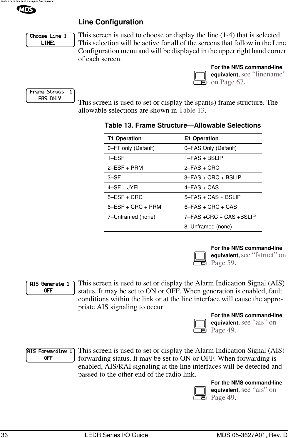
![MDS 05-3627A01, Rev. D LEDR Series I/O Guide 65Returns:led: Alarm LED ONline Attributes of lines (cables) used with the radio’s T1 or E1 Interface.This command is used to set or display the internal pulse template selec-tion used by the LEDR interface to compensate for signal distortion cre-ated by various lengths and types of interface cables.The [linelist] variable represents a list of line interfaces. It can consist of a single line number or line name, a comma-separated list of line num-bers or line names, a range of line numbers (i.e., 1–4), or if linelist is not given all lines will be displayed. See Table 19 on Page 59 for a list of line numbers.Usage For T1: line [linelist] [cable length<0–4>] [spec] T1 interfaces require setting of a minimum of two variables: ITU cable specification and cable length. Table 21 shows the specification options and Table 22 lists values used for various lengths of standard 100 Ω twisted pair cablesTable 21. ITU Cable Specifications—Subcommand [spec]Usage For E1: line [linelist] [spec] The only cable specification needed for E1 is the ITU cable type. Table 23 lists the specification values for two standard 120 Ω ITU-T G.703 cablesTable 23. E1 Cable Specifications—Subcommand [spec]Specificationg.775 (Default)i.431FT1E1FE1FT1Table 22. Cable Length Values—Subcommand [cable length]Value Line Length (Meters) Line Length (Feet)0 0.3 to 40 (default) 1 to 133 feet (default)1 40 to 81 133 to 2662 81 to 122 266 to 3993 122 to 163 399 to 5334 163 to 200 533 to 655Specificationg.775 (Default)i.431E1FE1](https://usermanual.wiki/GE-MDS/DS-LEDR700S/User-Guide-312318-Page-73.png)
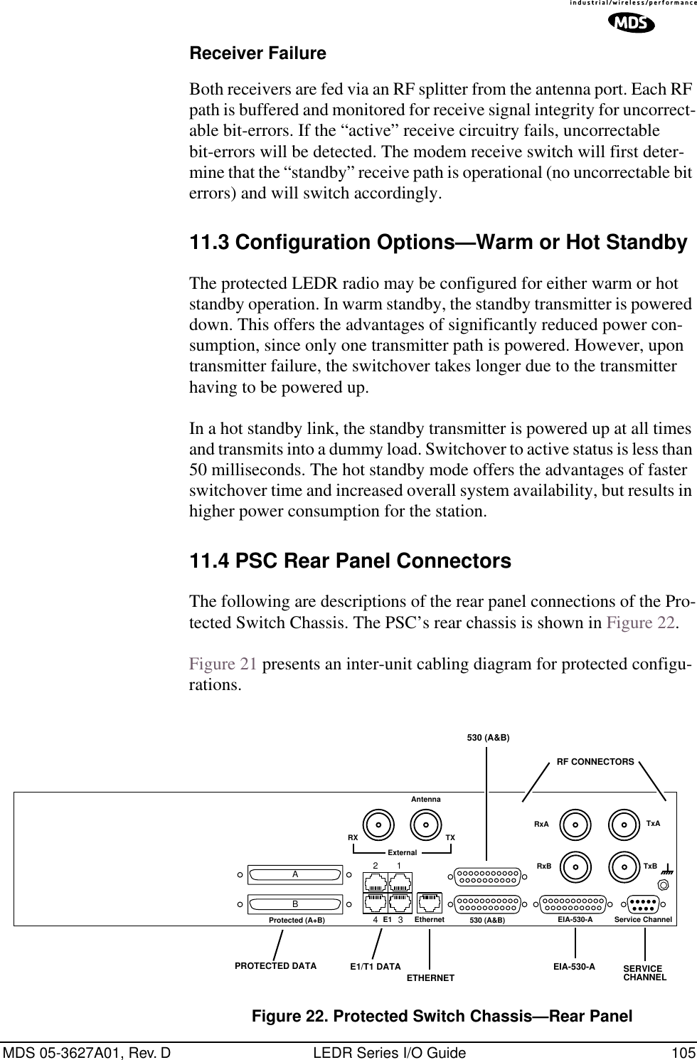
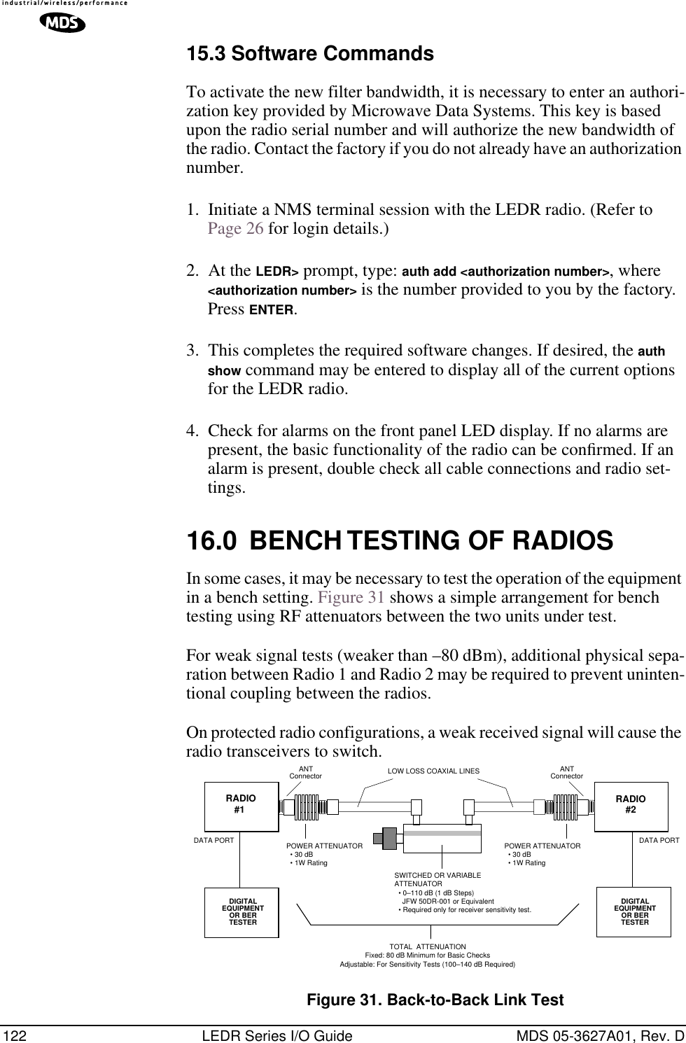
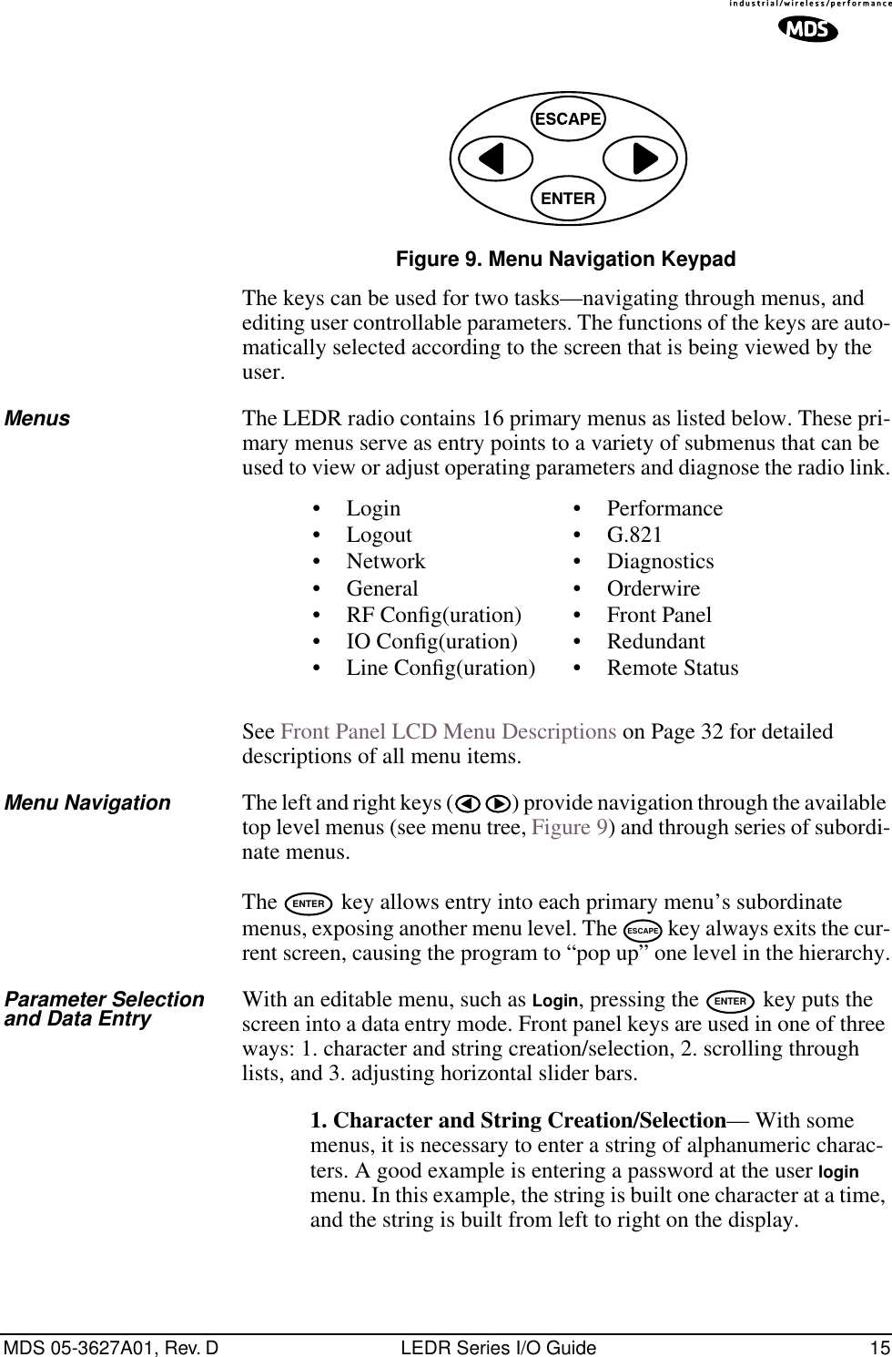
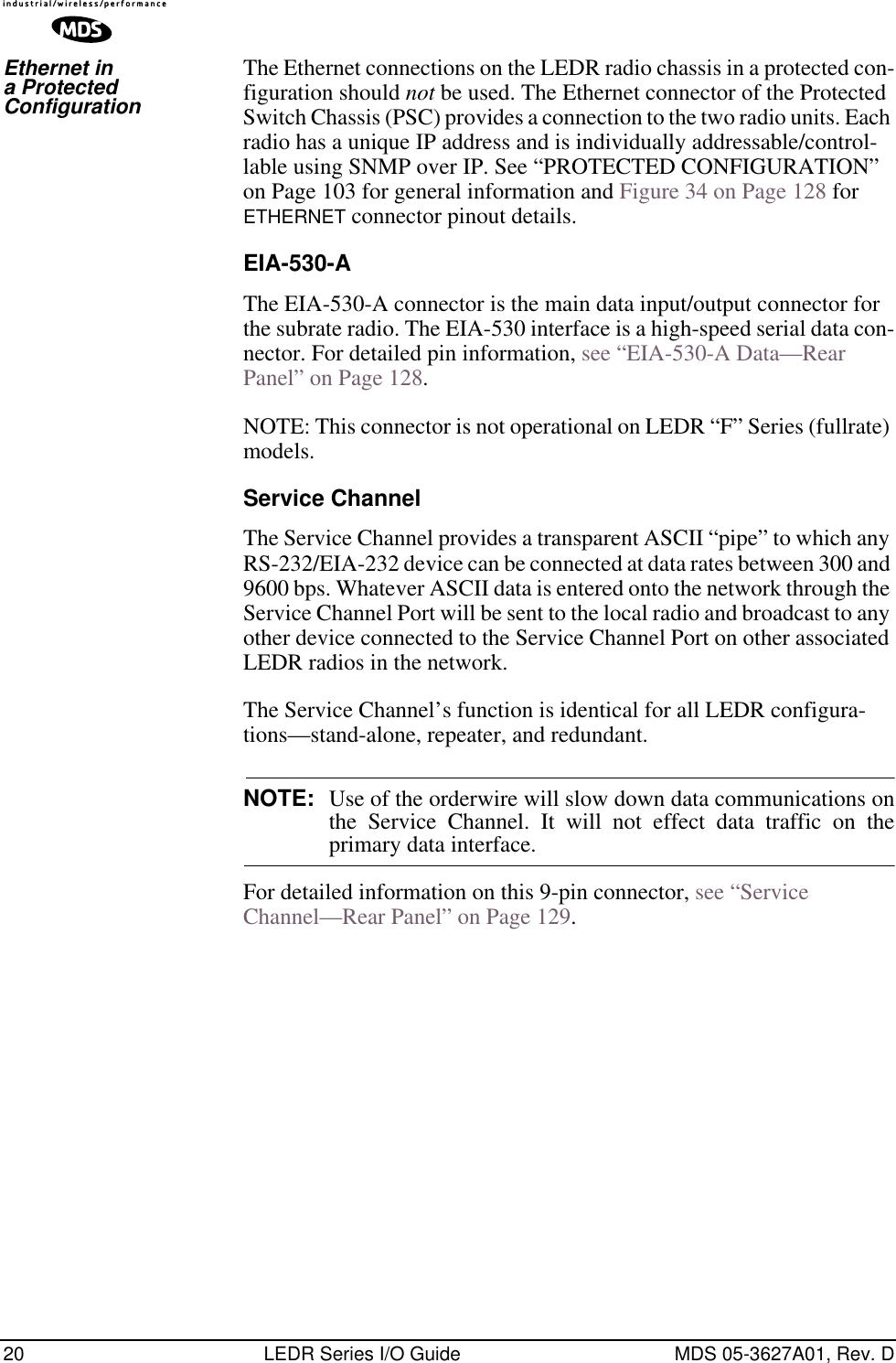
![66 LEDR Series I/O Guide MDS 05-3627A01, Rev. DCommand Example:LEDR> lineReturns:line {LINE1} {cable}: ITU-T G.703 120 Ω Twisted Pair{spec}: i.431line {LINE2} {cable}: ITU-T G.703 120 Ω Twisted Pair{spec}: g.775line {LINE3} {cable}: ITU-T G.703 120 Ω Twisted Pair{spec}: g.775line {LINE4} {cable}: ITU-T G.703 120 Ω Twisted Pair{spec}: g.775linecode Line CodeUsage: linecode [linelist] [B8ZS|AMI|HDB3]This command sets or displays the radio’s linecode (T1: B8ZS or AMI; E1: HDB3 or AMI).The [linelist] variable represents a list of line interfaces. It can consist of a single line number or line name, a comma-separated list of line num-bers or line names, a range of line numbers (i.e., 1–4), or if linelist is not given all lines will be displayed. See Table 19 on Page 59 for a list of line numbers. The most typical Fractional-T1 selection is to choose B8ZS for all ports by entering linecode b8zs and E1 interfaces choose HDB3 for all ports by entering linecode hdb3.Example Response:linecode: HDB3linemap Line Mapping Usage: linemap [maplist]This command is used to set or display the current span mapping con-figuration for E1 and T1 configurations. The maplist variable consists of from 1 to 4 alpha-numeric characters specifying line interface to span mapping. Valid numbers are 1–4. Valid span characters are a–d.Example: Entering linemap 1d 2b 3a 4c causes the following:maps line 1 to span dmaps line 2 to span bmaps line 3 to span amaps line 4 to span cE1FT1FE1E1FT1FE1](https://usermanual.wiki/GE-MDS/DS-LEDR700S/User-Guide-312318-Page-74.png)
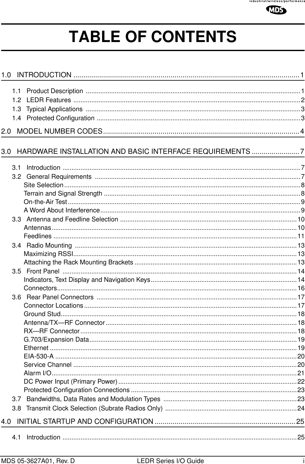
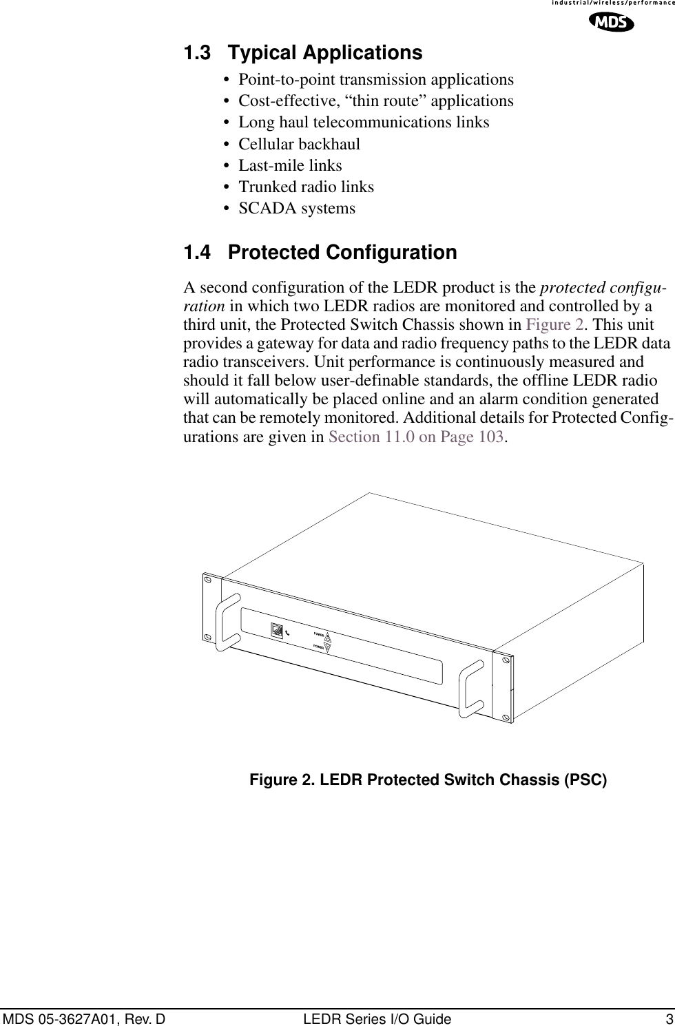
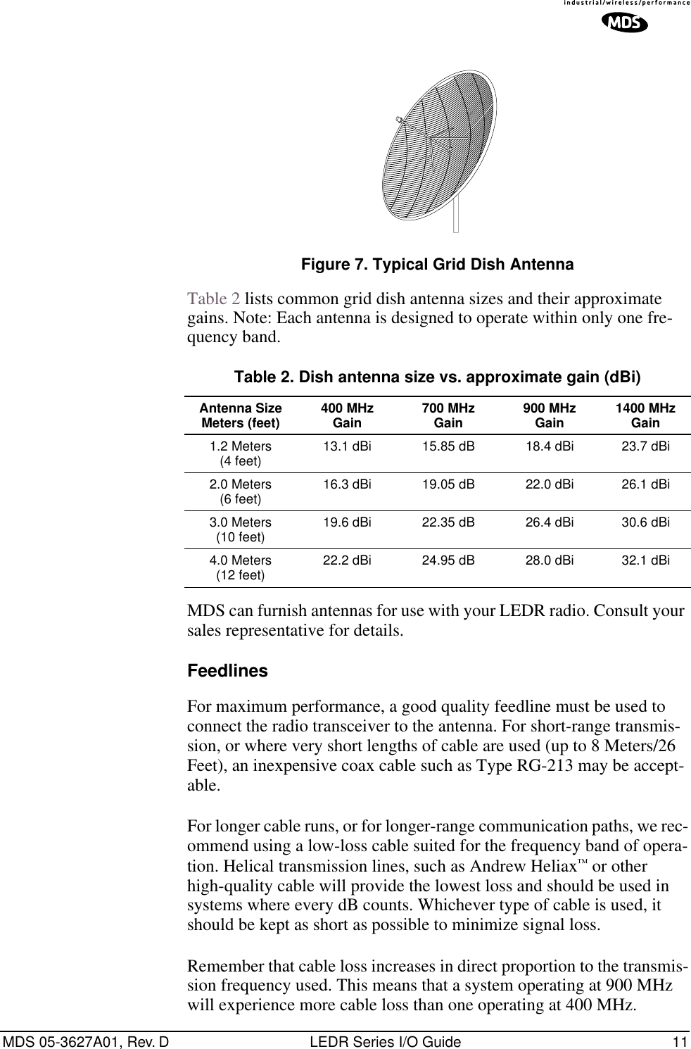
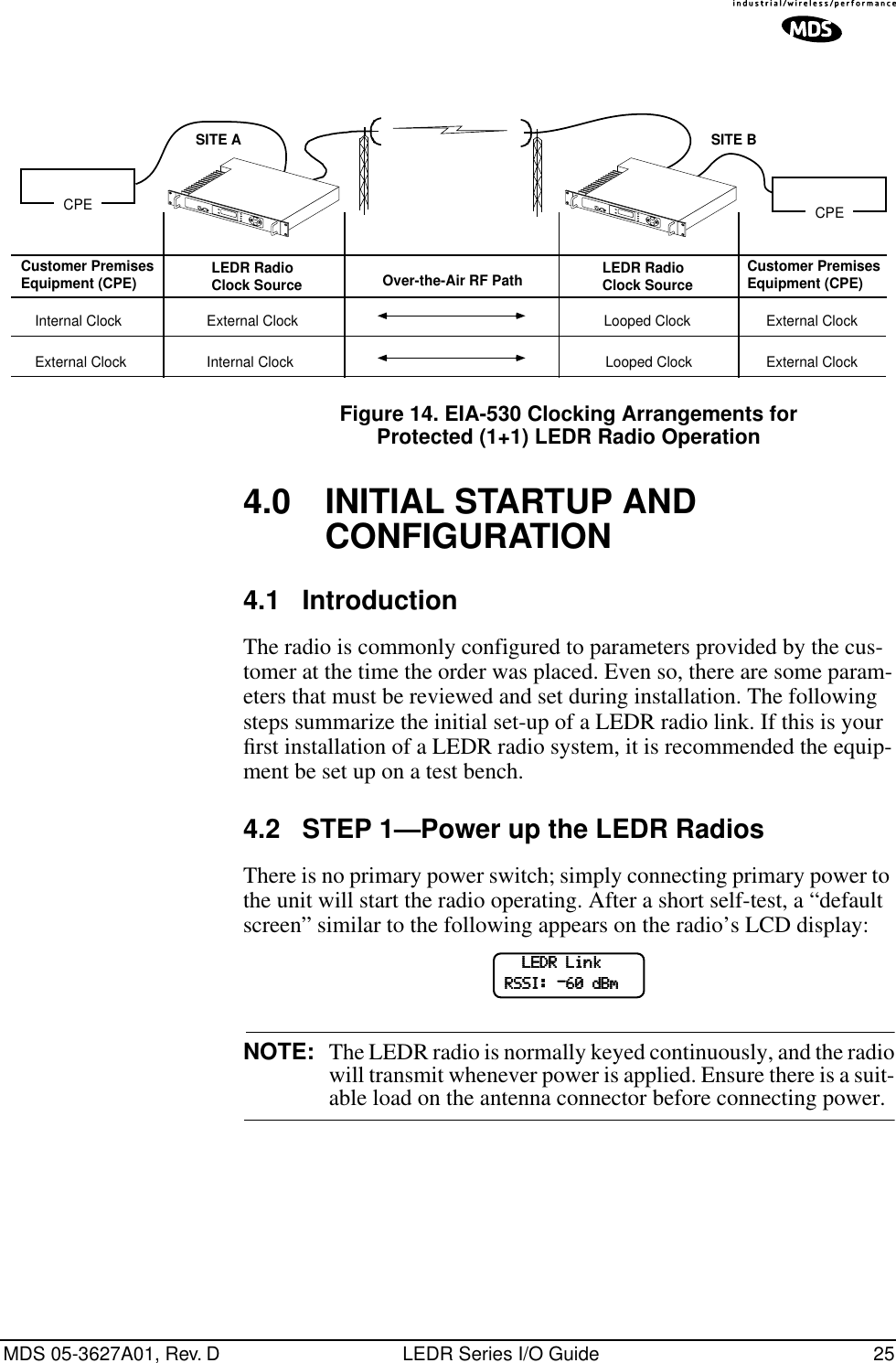
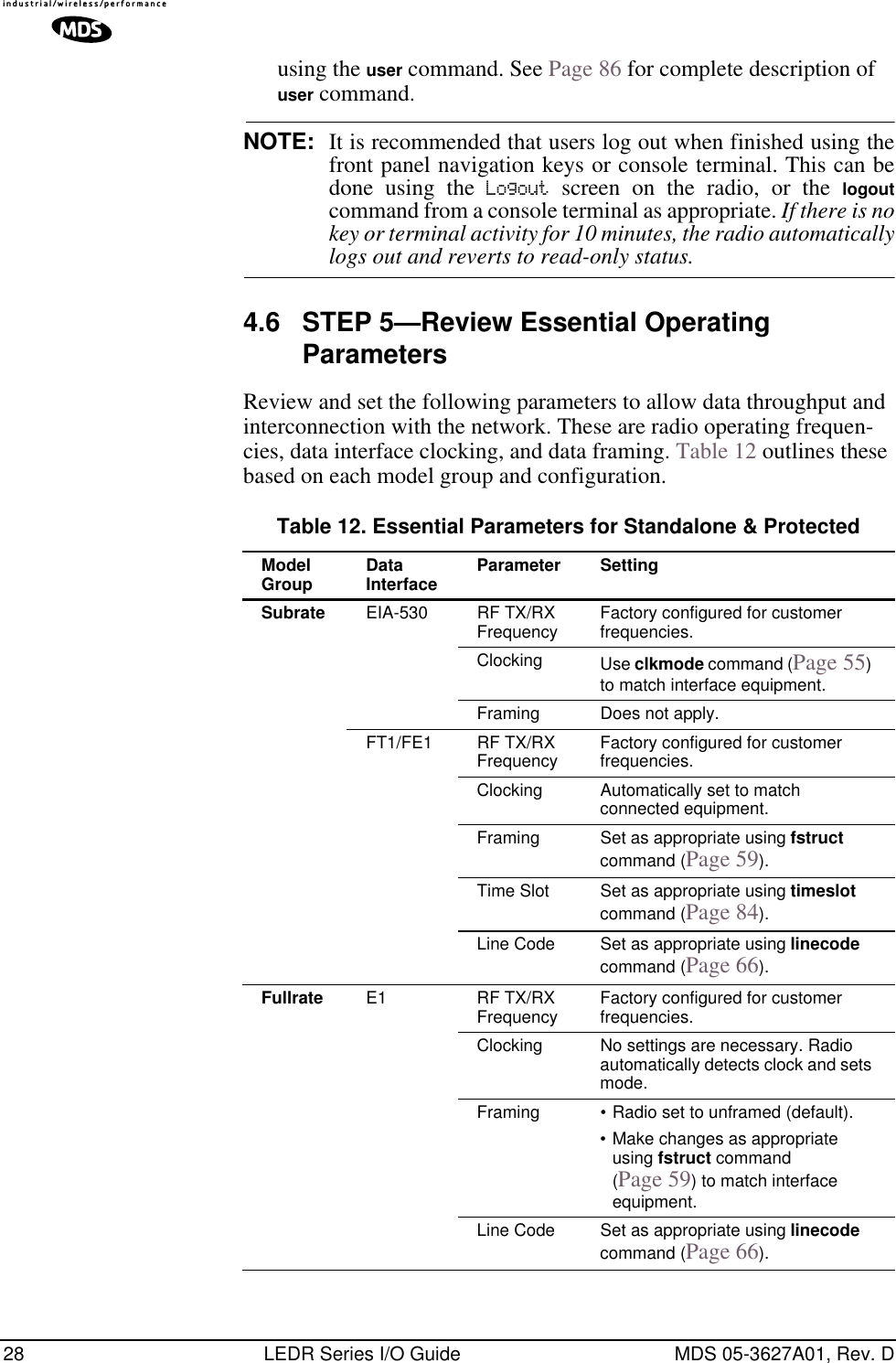
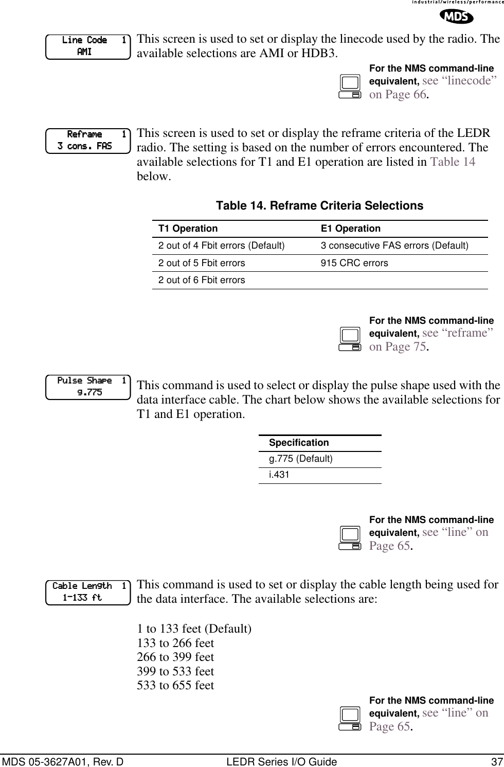
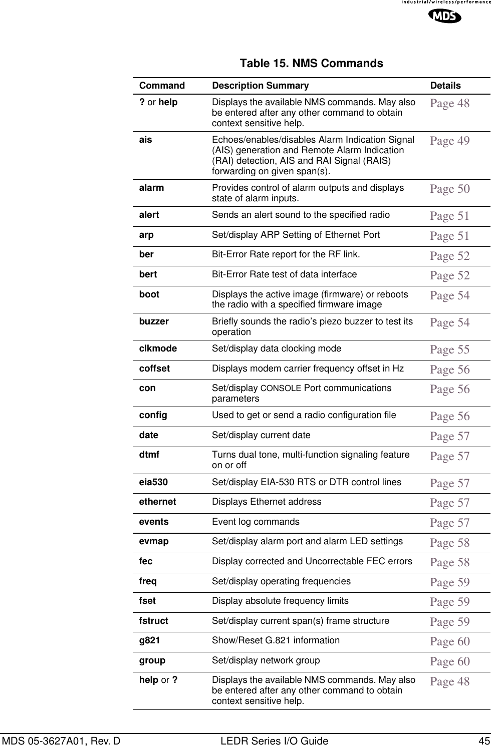
![MDS 05-3627A01, Rev. D LEDR Series I/O Guide 67NOTE: FE1/FT1 always use Span A.Figure 16 shows the example pictorially. There are no restrictions of which lines are mapped to which data channel spans.Invisible place holderFigure 16. Example of LinemappingNOTE: The cluster of four RJ-45 jacks on the rear of the radio is coded from left to right as 1, 2, 3 and 4 as viewed from the outside of the chassis.linename Line Name Usage: linename <linelist> <namelist>This command is used to set or display meaningful names of up to 16 characters to the four possible line interfaces.The [linelist] variable rep-resents a list of line interfaces. It can consist of a single line number or line name, a comma separated list of line numbers or line names, a range of line numbers (i.e., 1–4) or, if linelist is not given, all lines. See Table 19 on Page 59 for a list of line numbers.The namelist variable consists of a list of names. It can consist of a single name or a comma/whitespace-separated list of names. Names can be up to 16 characters long.linerr Line ErrorsUsage: linerr [linelist] [on|off]This command measures and displays the line performance between the radio and customer equipment. Entering the command linerr on will ini-tialize the line error measurement feature. The [linelist] variable repre-sents a list of line interfaces. It can consist of a single line number or line name, a comma-separated list of line numbers or line names, a range of line numbers (i.e., 1–4), or if linelist is not given all lines will be dis-played. See Table 19 on Page 59 for a list of line numbers.log Log of Events3421Span ASpan BSpan CSpan DLEDR LINE E1/T1 SPAN(RJ-45 JACK)E1FT1FE1E1FT1FE1](https://usermanual.wiki/GE-MDS/DS-LEDR700S/User-Guide-312318-Page-75.png)
![68 LEDR Series I/O Guide MDS 05-3627A01, Rev. DUsage: log [subcommand] [<argument>]Subcommands: view [critical|major|minor|inform]clearsend [filename] [hostIP]This command is used to display and manage the event log file. Without a subcommand, the complete log file will be displayed one page at a time. If you are interested in less than the full report, use one of the fol-lowing subcommands: view—Sets or displays the types of events to be displayed. clear—Resets the event log and purges all events from memory. send—Uploads the event log information to an IP address using TFTP protocol in a way similar to the config command. (See config command on Page 56.)NOTE: When setting up a link for the first time, after powering up theunit, you may want to clear the event log. After logging in asSUPER, enter the command log clear.login Log into the radio’s CONSOLE portUsage: login [username]This command allows access to configuration and diagnostics informa-tion as allowed by the radio system administrator. You can shorten the login sequence by following the login command with the user/account name (username).Example:LEDR> loginReturns:Username>Type: fieldserv (or appropriate user name)Returns:Password>Type: (password)NOTE: User names and passwords must not exceed eight charactersand are case sensitive. Do not use punctuation marks.See user command on Page 86 for more information on user access levels.](https://usermanual.wiki/GE-MDS/DS-LEDR700S/User-Guide-312318-Page-76.png)
![MDS 05-3627A01, Rev. D LEDR Series I/O Guide 69NOTE: Only one user can be logged in through the CONSOLE Port ata time. Any new login will close the previous user/account.Other users can login simultaneously through the ETHERNETPort or front panel.logout Logout of the LEDR radioUsage: logoutThis command is used to log out a user. Subcommands:loopback Loopback Functions The loopback command is used to set or display the loopback mode that can be used for diagnostic purposes. Entering loopback without any parameters displays the current loopback mode.Various data loopback modes can be used for diagnostic purposes. To loop back Line Interface 1 towards itself, use loopback iol 1. To loop back all line interfaces towards themselves and test the T1 option, use loop-back local. To loop back all data at the remote site towards the RF path, use loopback remote. Entering loopback without any parameters displays the current loopback mode.Usage 1 for Fractional-T1: loopback [none|rf|local|remote|iol [linelist]|ior [linelist] <timeout>]Usage 1 Subcommands:iol—The iol subcommand, for “I/O local,” refers to the local line loop-back.local—Enables a local digital loopback mode. With this test, incoming bits on the EIA-530 interface are sent back out the radio’s DATA con-nector before the modem module. This can be used to verify proper interconnection between the radio and the connected equipment. None of the radio’s RF circuitry is involved in this test. (This description covers only EIA-530 operation.) For T1/E1 operation, the local subcommand enables a local digital MUX loopback in the radio transceiver’s FT1 Interface Board before going out to the main transceiver board.none—Disables all loopback operation. This is the mode for normal point-to-point operation. E1FT1FE1](https://usermanual.wiki/GE-MDS/DS-LEDR700S/User-Guide-312318-Page-77.png)
![70 LEDR Series I/O Guide MDS 05-3627A01, Rev. Dremote—EIA-530 Operation: Instructs the radio at the other end of the link to “echo” all of the data it receives. This is an effective way of testing the entire communications system, including the transmission path over the air. (In the event of a communications failure with the remote radio, the message “Remote Error” is displayed, and no loop-back mode is selected. T1/E1 Operation: The remote subcommand mimics the ior subcommand described below.rf—Enables an RF loopback mode. This mode allows testing of the local radio transceiver’s transmit and receive chain. The receiver is rechan-neled to the transmitter frequency.NOTE: RF loopback testing is a valuable diagnostic tool, but it shouldnot be considered an exhaustive test of the transceiver. In somecases, interaction between the transmit and receivephase-locked loops (PLLs) can occur, causing erroneousresults during testing. Changing the transceiver’s RF outputsetting may resolve these problems. Also, in some configura-tions, insufficient signal strength for RF loopback testing mayexist.In addition, on all LEDR radios except the LEDR 1400 Series,the transmit and receive frequencies must be within the samesubband for RF loopback to function.Variables:ior—An abbreviation for “I/O remote”, refers to the remote line loop-back. Remote loopback port selection is relative to the local port. The radio link will translate any line mapping to select the correct physical remote port to loop back, based on the selected local port.linelist—Represents a list of local line interfaces. It can consist of a single line number or line name, a comma-separated list of line numbers or line names, a range of line numbers (i.e., 1–4), or if linelist is not given all lines. See Table 19 on Page 59 for a list of line numbers.timeout—The timeout variable may be set between 0 minutes (never time out) and 60 minutes.Usage 2: loopback [inb|outb] [linelist] [on|off] [-u <code>] [-d <code>] Usage 2 (E1) subcommands:inb—Refers to the inband loopback configuration.outb—Refers to the outband Extended Super Frame (ESF) loopback configuration.FT1](https://usermanual.wiki/GE-MDS/DS-LEDR700S/User-Guide-312318-Page-78.png)
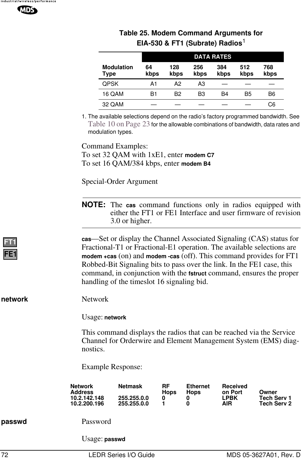
![MDS 05-3627A01, Rev. D LEDR Series I/O Guide 71linelist—Represents a list of local line interfaces. It can consist of a single line number or line name, a comma-separated list of line numbers or line names, a range of line numbers (i.e., 1–4) or, if linelist is not given, all lines. See Table 19 on Page 59 for a list of line numbers.on|off—To turn the loopback feature on or off.-u <code>—Allows setting of the inband|outband loopback upcode.The inband code consists of 1-7 bits, binary format.Example: 00001 -d <code>—The subcommand allows setting of the inband|outband loop-back downcode.The outband code consists of 6 bits within the 16 bit ESF data link codeword.Example: 000111within 16 bit codeword: 0<000111>0 11111111model Radio Model NumberUsage: modelThis command displays the radio model number. This information is programmed at the factory and cannot be changed. modem Modem Usage: modem [matrix id] [+cas]This command sets or displays the radio modem modulation type and data rate. Table 24 shows the alphanumeric codes that can be entered for fullrate radios and Table 25 for codes for subrate radios. Note that the E1 selections are only valid on fullrate radios. 1. The available selections depend on the radio’s factory programmed bandwidth. See Table 10 on Page 23 for the allowable combinations of bandwidth, data rates and modulation types.Table 24. Modem Command Arguments for E1 (Fullrate) Radios1DATA RATESModulation Type 1xE1 2xE1 3xE1 4xE1QPSK A7 ———16 QAM B7 B8 ——32 QAM C7 C8 C9 C10](https://usermanual.wiki/GE-MDS/DS-LEDR700S/User-Guide-312318-Page-79.png)
![MDS 05-3627A01, Rev. D LEDR Series I/O Guide 73This command is used to change the password for the user currently logged in. A maximum of 8 characters is allowed, and it is case sensi-tive.ping Ping IP Address (Send ICMP Echo Request)Usage: ping [ip address] [reps]This command is used to verify the accessibility of any IP address on the network to determine availability and measure network response time. This command requires proper IP Routing and IP connectivity.ipaddress—IP address to which you will send the requestreps - Number of requests-to-send (default = 1, maximum = 1000) Example:LEDR> ping 10.2.233.12 5Example Response:PING 10.2.233.12: 56 data bytes64 bytes from 10.2.233.12: seq=1, ttl=255, rtt=49ms64 bytes from 10.2.233.12: seq=2, ttl=255, rtt=6ms64 bytes from 10.2.233.12: seq=3, ttl=255, rtt=9ms64 bytes from 10.2.233.12: seq=4, ttl=255, rtt=33ms64 bytes from 10.2.233.12: seq=5, ttl=255, rtt=12mspll Phase Locked LoopDisplays current TX & RX frequencies, and TX/RX PLL status.Example Response:pll: Tx Freq = 438075000 Hz, Rx Freq = 428075000Tx PLL Status: LockedRx PLL Status: Lockedpmmode Power Measurement ModeUsage: pmmode <on|off>This command is used to generate an unmodulated carrier on the trans-mitter frequency for the purpose of measuring RF output power or fre-quency stability using a spectrum analyzer.Example Response:pmmode: offNOTE: Enabling the power measurement mode (pmmode on) will takethe local link down (out-of-service).](https://usermanual.wiki/GE-MDS/DS-LEDR700S/User-Guide-312318-Page-81.png)
![74 LEDR Series I/O Guide MDS 05-3627A01, Rev. Drdnt Redundant (Protected Operation)The rdnt command is used to manage protected operation of the LEDR radio and display operating status.Usage: rdnt [subcommand] [arguments]Subcommands: activedefaulthitlessipmodensdstatusswxcvrtempmodeThe following subcommands are divided into two groups: read only and read and set.Read Only:active—Shows whether the currently selected transmitter is active or inactive.default—Displays whether the radio is the default radio in a protected configuration. status—Protected status of this radio and the sibling radio.Read & Set:hitless—Sets or displays the hitless (error-free) switching status of the receivers. It can be enabled or disabled using the hitless on|off command. In protected operation, either receiver (regardless of which transmitter is active) can provide data to the user data port(s) in hitless mode. In non-hitless mode, only the receiver in the active radio provides received data. Radios operated in a space-diversity configuration must be config-ured to use hitless switching.ip—Used to set or display the IP address to be kept in the memory of this unit of the associated (sibling) radio in a redundant pair of transceivers. In other words, the rdnt ip setting of the top radio in a protected pair must be set to the bottom radio’s IP address for proper switching and net-work-management functionality.](https://usermanual.wiki/GE-MDS/DS-LEDR700S/User-Guide-312318-Page-82.png)
![MDS 05-3627A01, Rev. D LEDR Series I/O Guide 75NOTE: The associated radio (sibling) IP address should beprogrammed to the IP address of the other radio connected tothe Protected Switch Chassis. The associated radio IP addressis used by the redundant radio to share information betweenthe units. This address is necessary for warm-standbyswitching. The associated radio IP address parameters do notaffect IP routing and forwarding, SNMP, or Telnet.The rdnt swxcvr will not operate correctly if this parameter isnot set correctly.mode [#]—Set or display one of three redundant operation modes (0 = Standalone, 1 = 1+1 Hot Standby, 2 = 1+1 Warm Standby).status—Shows the state of both radios. Two status lines are displayed; This Radio and Other Radio.swxcvr—Forces a switchover to the inactive radio transceiver. (The newly selected unit becomes the active transceiver.) The rdnt ip param-eter must be configured correctly on both radios in order for the swxcvr command to operate correctly.NOTE: The rdnt swxcvr command should not be used within 2 minutesof a power-up to ensure reliable communications existbetween the two transceivers.temp—Set or display an over-temperature threshold (final amplifier temperature in degrees Celsius), at which temperature switchover to the other radio occurs.nsd—Enable or disable network self-discovery between the units in a protected pairExample Response for rdnt command:rdnt {status}: This Radio = OKrdnt {status}: Other Radio = OKrdnt {active}: inactiverdnt {mode}: 1+1 Hot Standbyrdnt {ip}: 10.2.233.12rdnt {hitless}: onrdnt {default}: nordnt {temp}: 50rdnt {nsd}: onreframe Reframe Criteria for User Interface Ports Usage: reframe [linelist] [2of4 | 2of5 | 2of6 | CFAS | CRC]This command is used to set or display the reframe criteria. The [linelist] variable represents a list of line interfaces. It can consist of a single line number or linename, a comma separated list of line numbers or line names, a range of line numbers (i.e., 1–4), or if linelist is not given all lines. See Table 19 on Page 59 for a list of line numbers.E1FT1FE1](https://usermanual.wiki/GE-MDS/DS-LEDR700S/User-Guide-312318-Page-83.png)
![76 LEDR Series I/O Guide MDS 05-3627A01, Rev. DFor Fractional-T1:2of4 – 2 out of 4 Fbit errors (default)2of5 – 2 out of 5 Fbit errors2of6 – 2 out of 6 Fbit errorsFor E1:CFAS – Consecutive FAS errors (default)CRC – 915 CRC (rx framer only)reprogram Load Radio Firmware Into LEDR RadioUsage: reprogram [subcommand] [<argument>]Subcommands:network [filename] [hostIP]statusThis write command loads the radio application software (firmware) into the LEDR chassis from an external resource using Trivial File Transfer Protocol (TFTP). A TFTP server must be running on the net-work and properly configured to serve the necessary file(s). See “OPTION 3: Uploading Firmware from a Remote Server via Ethernet” on Page 97 for further details.rfocal Transmitter RF Output Calibration TableUsage: rfocal <freq region#> <cal-point#>This command starts the RFOUT Calibration Sequence and should only be used when directed by MDS factory personnel. CAUTION:This command is used to recalibrate the internal transmitterpower output metering circuitry and may affect the accuracy ofthe power output level measurement. Contact the TechnicalServices Department at MDS for further instructionsbefore using this command. Ask for technical publication,Retuning Procedure for LEDR II Radios, P/N 05-3633A01.Recalibration may be necessary if the radio’s transmittingfrequency has been significantly changed. For the LEDR 400and 900 radios, this is generally a change of more than tworadio channels. In addition, it is very important to verify thepower calibration is incorrect on the new frequency bymeasurement with a calibrated external wattmeter before usingthis command.The radio frequencies of the LEDR 1400 radio can be changedwithout impacting the accuracy of the power metering circuit’scalibration.Example Entry: rfocal](https://usermanual.wiki/GE-MDS/DS-LEDR700S/User-Guide-312318-Page-84.png)
![MDS 05-3627A01, Rev. D LEDR Series I/O Guide 77Example Response:Region 0Index 0, Rfout = 18 dbm, Gain = 17Index 1, Rfout = 20 dbm, Gain = 28Index 2, Rfout = 22 dbm, Gain = 47Index 3, Rfout = 25 dbm, Gain = 79Index 4, Rfout = 27 dbm, Gain = 110Index 5, Rfout = 30 dbm, Gain = 170Index 6, Rfout = 32 dbm, Gain = 210rfout RF Output Level MeasurementUsage: rfoutThis command displays the transmitter RF power output in dBm. See “Watts-dBm-Volts Conversion” on Page 129.rlogin Remote LoginUsage: [<toUnitID>} [<UserName>]The rlogin command is used to login to a remotely located radio via the CONSOLE Port. It can be used to log into any radio that appears in the network command display.route Routing Tables for IPUsage: route [command [destination] [mask netmask] [gateway] [port]]The route command is used to add, delete or modify the IP routing table entries. Other radios in the network are automatically added to the routing table using the radio’s “Network Self-Discovery.” Routing IP traffic to other devices via the radio’s management channel can be per-formed by adding routes to the radio’s routing table.Once the IP configuration is set using the ip command (Page 63), several routing entries will appear in the routing table. The first of these routes is the default route which has a destination address of 0.0.0.0. This route is used when a more appropriate route is not available. Thus it becomes the “catch-all” route. The second route that will appear is the default net-work route. This route has a destination address calculated by “anding” the IP address and subnet mask together. The Next Hop address of this entry will be the default gateway configured using the ip command and the Interface will be the default port. This route is used to tell the radio how to reach its base network.The third route that is added has a destination address of 127.0.0.1. This is known as the loopback route and is used when the radio sends a packet to its own IP address.Primary Commands:print —Show the current IP routing tableadd [address] mask [netmask] [gw] [port]—Add/Change a route](https://usermanual.wiki/GE-MDS/DS-LEDR700S/User-Guide-312318-Page-85.png)
![78 LEDR Series I/O Guide MDS 05-3627A01, Rev. Dgw is a gateway IP addressport is specified as either “ETH” or “AIR”delete [address] mask [netmask] [gw]—Delete a routegw is a gateway IP addressstored—Display all user-added stored routesflush—Deletes all stored routesdestination—Specifies the host to send commandCommand Arguments:mask—Where the mask keyword is present, the next parameter is interpreted as the netmask parameter.netmask—Specifies a sub-net mask value to be associated with this route entry.gateway—Specifies gateway IP addressport—Specifies IP port, either “ETH” or “AIR”Example 1 Entry:LEDR> route add 10.2.150.1 mask 255.255.255.255 10.2.150.101 airExample 1 Response:route: Route addedExample 2 Entry: LEDR> route storedExample 2 Response:Destination Net Mask Next Hop Interface10.2.150.1 255.255.255.255 10.2.150.101 AIR10.2.140.0 255.255.255.0 10.2.227.51 ETHExample 3 Entry:LEDR> route printExample 3 Response:Destination Net Mask Next Hop Interface0.0.0.0 0.0.0.0 0.0.0.0 ETH10.2.140.0 255.255.255.0 10.2.227.51 ETH10.2.150.1 255.255.255.255 10.2.150.101 AIR127.0.0.1 255.255.255.255 10.2.227.5 LPBK](https://usermanual.wiki/GE-MDS/DS-LEDR700S/User-Guide-312318-Page-86.png)
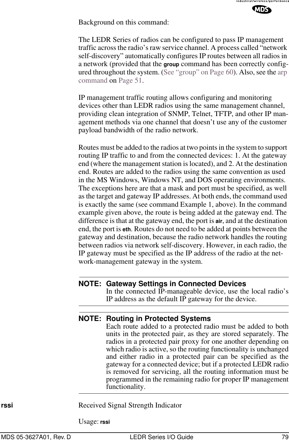
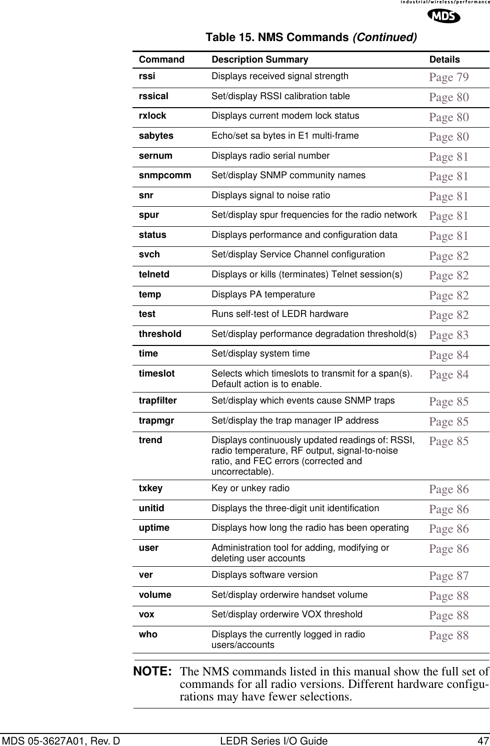
![80 LEDR Series I/O Guide MDS 05-3627A01, Rev. DThis command displays the received signal strength. The measurement is in dBm. Therefore, an RSSI of –80 dBm is stronger than a –100 dBm signal. There may be a time delay between moving the antenna and updating of the RSSI display. Be sure to allow adequate time between antenna movements and observations.rssical RSSI CalibrationUsage: rssical <freq region#> <cal-point#>This command starts the RSSI Calibration Sequence. See rfocal com-mand on Page 76 for conditions.CAUTION:This command should never be used unless calibrated testequipment has shown the radio to have inaccurate RSSIcalibration. Contact the Technical Services Group atMDS for further instructions before using thiscommand. Example entry: rssicalExample Response:Region 0Index 0, RSSI = –110 dbm, Gain = –104Index 1, RSSI = –90 dbm, Gain = –40Index 2, RSSI = –75 dbm, Gain = +1Index 3, RSSI = –60 dbm, Gain = +28Index 4, RSSI = –45 dbm, Gain = +61Index 5, RSSI = –30 dbm, Gain = +97rxlock Receiver locked onto Remote radioUsage: rxlockThis command displays the current modem synchronization status.Example Response:: rxlock: Modem is lockedsabytes SA Bytes in E1 Multi-framing Usage: sabytes [linelist] [bytes <bytelist>]This command is used to set or display SA bytes in E1 multiframing. The [linelist] variable represents a list of line interfaces. It can consist of a single line number or line name, a comma-separated list of line num-bers or line names, a range of line numbers (i.e., 1–4), or if linelist is not given all lines. See Table 19 on Page 59 for a list of line numbers.The bytelist variable consists 5 hex bytes (i.e., 3c) representing SA[4-8]. To keep a bytes present value when modifying higher bytes (i.e., modi-fying SA[7] only) use a * character in the respective byte position. Example: sabytes 1 bytes *,*,*,3c changes only SA[7] for line 1 to 3c.E1](https://usermanual.wiki/GE-MDS/DS-LEDR700S/User-Guide-312318-Page-88.png)
![MDS 05-3627A01, Rev. D LEDR Series I/O Guide 81sernum Serial Number of RadioUsage: sernumThis command displays the serial number of the radio. The number dis-played with this command matches the serial number printed on the serial number sticker on the radio chassis.snmpcomm SNMP Community NamesUsage: [<read|write|trap>][<string>]This command is used to set or display SNMP community names. Com-munity names are passwords that are required to match at the SNMP management station and each radio or other SNMP agent. You can add security to the radio system’s network management by choosing non-default community names (listed in the example) and setting the community names in your management software to match.Example Response:: snmpcomm {read}: publicsnmpcomm {write}: privatesnmpcomm {trap}: publicsnr Signal-to-Noise Ratio of Incoming RF SignalUsage: snrThis command displays the signal-to-noise ratio (SNR) of the received signal in dB. The SNR is an indication of the quality of the received signal. The higher this number, the higher the quality of the received signal. SNR readings are invalid when the receiver is unlocked. See rxlock command for details.spur Spur FrequenciesUsage: spur [<Frequency>|clear|default] [<frequencyToClear>]This command is only operative for LEDR 1400 Series radios. It is used to set or display the spur frequencies for the radio network. Add a dec-imal point “.” to the end of a frequency input to signify MHz unit.status StatusUsage: statusThis command is used to display key performance and configuration data.Example Response:status {Tx Freq}:438075000status {Rx Freq}:428075000status {Bandwidth}:100 kHzstatus {Data Rate}: 256 kbpsstatus {Interleave}: 1](https://usermanual.wiki/GE-MDS/DS-LEDR700S/User-Guide-312318-Page-89.png)
![82 LEDR Series I/O Guide MDS 05-3627A01, Rev. Dstatus {Clock Mode}:internalstatus {RSSI}:–78 dBmstatus {SNR}:28 dBstatus {Rx Lock}:Lockedstatus {Tx RF Out}:30 dBmstatus {TxKey}: Keyedstatus {Temp}:37 Degrees Cstatus {IP Address}: 192.168.11.49status {IP Netmask}: 255.255.0.0status {IP Gateway}: 0.0.0.0svch Service Channel SettingsUsage: svch [subcommand] [<argument>]Subcommands: baud [300|1200|2400|4800|9600csize [5–8]parity [none|even|odd]stop [0–2]This command sets or displays the Service Channel settings. For further information, see “USING THE SERVICE CHANNEL” on Page 101.telnetd Telnet Display or Terminate SessionUsage: telnetd [kill session]This command is used to display or kill (terminate) the current Telnet session(s).Entry Example: telnetdResponse:Session Username Rem. Addr. Connectedtns0 ENGR 10.2.129.22 01/03/2003@ 13:57:17Use telnetd kill session to terminate the current session.temp Temperature of PA DeviceThis command displays the radio’s power amplifier (PA) temperature.Example Response:: temp: 35 Degrees C (PA Temperature)test Self-Test of Radio HardwareUsage: test [<0–n>|<testname>]This command starts a self-test function of the radio. There are several separate tests that can be run individually by specifying the test number after the command.CAUTION:Do not perform a transmitter PLL test while the radio iskeyed, or the radio’s receive LNA may be damaged.CAUTIONPOSSIBLEEQUIPMENTDAMAGE](https://usermanual.wiki/GE-MDS/DS-LEDR700S/User-Guide-312318-Page-90.png)
![MDS 05-3627A01, Rev. D LEDR Series I/O Guide 83NOTE: Performing a receiver or transmitter PLL test during normallink operation will take the link down for the duration of thetest and the re-synchronization interval.The internal self tests are listed in Table 26.threshold Threshold of Performance DegradationUsage: threshold [<level>]This command sets or displays the performance degradation threshold(s) of the LEDR radio, at which time events are logged and SNMP traps are generated. Setting these thresholds to zero or a negative number will disable event logging and trap generation for those param-eters.Example Response:: threshold {rssi}: 0threshold {snr}: 0threshold {coffset}: 0threshold {temp}: 110threshold {15mines}: 900threshold {15minses}: 900threshold {24hres}: 86400threshold {24hrses}: 86400rssi—dBm level below which an RSSI alarm is generated.snr—Value below which a signal-to-noise level alarm is generated.coffset—Maximum tolerable RF carrier frequency difference between the local LEDR unit’s transmit frequency and the incoming RF signal from the other LEDR radio.temp—Power amplifier temperature above which an alarm condition is generated.15mines—Number of errored seconds within the last 15 minutes.Table 26. Internal self tests Function Evaluated Number Name Flash Memory 0 flashDRAM Memory 1 dramConfiguration 2 configBattery 3 battRadio A- to-D Circuits 4 atodTransmitter Phase Locked Loop 5 txpllReceiver Phase Locked Loop 6 rxpllReal-Time Clock 7 rtcFPGA Logic 8 fpgaDSP 9 dspCODEC 10 codec](https://usermanual.wiki/GE-MDS/DS-LEDR700S/User-Guide-312318-Page-91.png)
![84 LEDR Series I/O Guide MDS 05-3627A01, Rev. D15minses—Number of severely errored seconds within the last 15 min-utes.24hres—Number of errored seconds within the last 24 hours.24hrses—Number of severely errored seconds within the last 24 hours.time Time of Internal ClockUsage: time [HH:MM[:SS]This command displays or sets the time of the radio’s internal real-time clock. The radio’s real time clock operates from an internal lithium bat-tery so it is running even if the radio has no DC power connected.The real time clock is fully compliant with Year 2000 standards.timeslot Time Slot AssignmentSelect which timeslots to transmit. This command has two uses; in Usage 1, the timeslots can be set or displayed. In Usage 2, all pending timeslots are committed/made active.The timeslots may be different at each end of the link. They will be monotonically mapped; that is, Slot 1 is mapped to Slot 13, Slot 2 is mapped to Slot 14, etc. To select timeslots 1 through 12, enter the com-mand timeslot 1-12. Usage 1: timeslot [-d] [slotlist]Usage 2: timeslot -cVariables:–dDisable timeslot(s)–cCommit pending timeslotsModifications to the timeslot list are kept pending until all available slots have been assigned. The user can choose to commit slots when the last available slot is added to the pending list, or by using the -c option. (See Usage 2.)The default action is to enable given timeslots. If no arguments are entered, the currently active timeslots and pending timeslots are dis-played.If rearrangement of timeslots is desired, some simple rules must be fol-lowed when CAS framing is used. Refer to the chart below for this dis-cussion, where “TS” = “Timeslot”:TS00 TS01–TS15 TS16 TS17–TS311M1NFE1FT1](https://usermanual.wiki/GE-MDS/DS-LEDR700S/User-Guide-312318-Page-92.png)
![MDS 05-3627A01, Rev. D LEDR Series I/O Guide 85If the timeslots are rearranged such that M is to the “left” of timeslot 16, and N to the “right,” then the timeslot numbers at the other end of the link must agree (M and N). They may be re-positioned within their part of the E1 frame (to the left or right of TS16) but may not be moved to the other side.The slotlist variable is a list of timeslots and can be a single slot number, comma separated list of slot numbers, or a range of slot numbers (i.e., 2-8). Timeslots can be entered in any order and are automatically con-figured. Extra slots will be ignored. Unassigned timeslots in the pending list are signified by MA (must assign).NOTE: Enough slots for the full data capacity of the modem settingmust be specified or the link will not synchronize.NOTE: FT1 timeslots are 1–24. E1 timeslots are 0–31.NOTE: In FE1 mode timeslot 0 is always selected. When frame struc-tures are selected that contain CAS (fstruct 4-7) timeslot 16must be selected.trapfilter Trap Filtering for SNMPUsage: trapfilter [<critical|major|minor|inform>]This command sets or displays which events cause SNMP traps. Fil-tering traps is done by category. Traps that are filtered are allowed to pass through the network-management system. (See trapmgr on Page 85 and snmpcomm on Page 81 for additional information.)trapmgr Trap Manager IP AddressesUsage: trapmgr [<1-5>] [<IP address>]This command sets or displays the trap manager IP addresses. These are the IP addresses of up to five network-management stations on which SNMP manager software is operating, and to which notifications of SNMP events (traps) are to be sent. The IP mask used for sending traps is that set by the ip command. (See “ip” on Page 63.)Example Response:: trapmgr: 1 = 10.2.129.22trapmgr: 2 = 0.0.0.0trapmgr: 3 = 0.0.0.0trapmgr: 4 = 0.0.0.0trapmgr: 5 = 10.2.129.1trend Trend of RF Performance IndicatorsUsage: trend [<rssi|temp|rfout|snr|fec|ifec|time|all>] [<display time (msec)>]](https://usermanual.wiki/GE-MDS/DS-LEDR700S/User-Guide-312318-Page-93.png)
![86 LEDR Series I/O Guide MDS 05-3627A01, Rev. DThis command is used to display continuously updated readings of: RSSI, radio temperature, RF output, signal-to-noise ratio, and FEC errors (corrected and uncorrectable). The display can be stopped by pressing Control-C on the terminal. If the trend command is used by itself or with all (trend all), all associated parameters will be reported. More than one argument can be used to dis-play several selected items in the desired order.NOTE: This command is not available from a Telnet session.txkey Radio Transmitter Keying StatusUsage: txkey [on|off]This command sets or displays the radio transmitter status. ON indicates the radio transmitter is keyed and transmitting. OFF indicates the trans-mitter is not keyed. unitid Unit Identification Number for Orderwire and NMSUsage: unitid [<ID>]This command sets or displays the radio’s unit identification number. This number is used for Orderwire signaling and by the NMS (Network Management System). (See “USING ORDERWIRE” on Page 99.) The factory default is the last three numbers of the unit serial number. (1-999)uptime Up TimeUsage: uptime This command displays how long the radio has been powered-on.user User Account InformationUsage: user [subcommand] [<argument>]Subcommands: add <user> <pass> <perm>del <user>perm <user> <perm>passThis command provides administrator access for setting new user accounts and permission levels. NOTE: The password (pass) and user names are case sensitive andmay not exceed eight characters. Two quotation mark charac-ters ("") may be used as a “blank” password. If quotationmarks are used, the shift key or cap lock keys must bedepressed.](https://usermanual.wiki/GE-MDS/DS-LEDR700S/User-Guide-312318-Page-94.png)
![MDS 05-3627A01, Rev. D LEDR Series I/O Guide 87User permission (perm) may be set to: read (r), write (w), network (n) or administrator (a). The privileges granted by each level are as follows:• Read (r) is the lowest level of user access and allows radio informa-tion to be viewed only. Changes to radio settings are not allowed.• Write (w) allows most, but not all radio settings to be changed.• Network (n) allows everything permitted by lower levels, and also allows changes to the radio’s IP configuration.• Administrator (a) allows everything permitted in lower levels, and also allows changes to be made to user accounts (add, delete, mod-ify). It is normally used by a System Administrator or other person responsible for the radio system.Example entry: user add fieldserv secret wThe above example shows the command string for adding a new user (fieldserv), with “write” permission and a password of secret.Example Response: user: Command CompleteNOTE: If you are logging in for the first time since the radio wasshipped from the factory, refer to Page 26 for important logininformation.ver Version of Firmware/HardwareUsage: ver [frw|hdw|ext]This command displays radio version information for firmware (frw), hardware (hdw) and Extended Version Information (ext).Example 1: LEDR> ver frwResponse 1: ver: LEDR Part #06-3451A01ver: 2.4.3 (Version of firmware P/N above)Example 2: LEDR> ver hdwResponse 2: ver: {Hardware version}: AExample 3: LEDR> ver extResponse 3: ver: Part #06-3451A01ver: 2.4.3ver:ver: Image 1ver: Region Expected Upgradever: Firmware 2.4.3ver: DSP 1.1.0ver: FPGA Ver1.22](https://usermanual.wiki/GE-MDS/DS-LEDR700S/User-Guide-312318-Page-95.png)
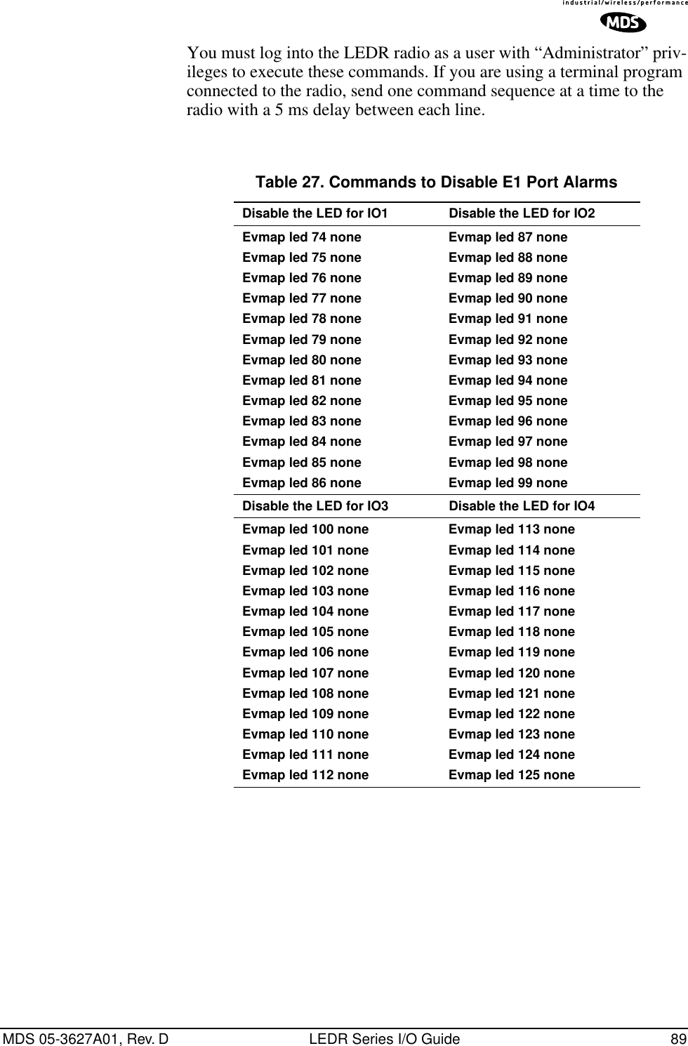
![88 LEDR Series I/O Guide MDS 05-3627A01, Rev. Dver: Scripts Ver1.44 ver: Option Ver1.56ver:ver: Image 2 (Active)ver: Region Expected Upgradever: Firmware 2.4.3ver: DSP 1.1.0ver: FPGA Ver1.22ver: Scripts Ver1.44ver: Option Ver1.56ver {Active code}: compiled Aug 15 2000 08:47:46Note: Blank lines following “Ver:” are spaces used as vertical separations between data groups.volume Volume of Orderwire EarpieceUsage: volume [<level (0–255)>]This command sets or displays the orderwire handset volume.Example Response:: volume: 100vox Voice Operated TransmitUsage: vox threshold <1–100>The vox command sets or displays the level/threshold at which the order-wire microphone will key the transmitter.NOTE: When the orderwire microphone is spoken into, the audio willbe heard by all LEDR radios in the network which currentlyhave a handset plugged into the front panel handset jack. Onlyone station can transmit at a time; the circuit is half-duplex.Example Response:: vox: 5who Identifies who is currently logged on to the Network Management PortsUsage: whoThis command displays users currently logged in to the radio operating system.6.5 Disabling the Front Panel Alarm LED for Unused E1 Option PortsTo disable the ALARM LED on the front panel for a particular E1 port, use the commands found in Table 27 below according to the E1 port number. When alarm events are pending, the alarm condition for the unused E1 ports remains until a valid input signal (as defined by G.703) is applied.](https://usermanual.wiki/GE-MDS/DS-LEDR700S/User-Guide-312318-Page-96.png)
![MDS 05-3627A01, Rev. D LEDR Series I/O Guide 91Radio-Specific data is:• Frequencies • Target Power• Thresholds• Calibration Data• IP Address• IP Routing Table• Network SettingsStandard radio data are the configuration parameters that are common in all LEDR radios. Both types of data can be uploaded and downloaded between the radio and a PC. It is up to the user to decide whether to download both types or just the standard (core) data. Once the data is on a PC, the file can be edited off-line, for example, the configuration data, if desired. The cus-tomized configuration file can then be downloaded to other LEDR radios in your system from your PC.7.2 Setup by TFTPTo use this function the user will need:• A PC with a TFTP server running.• The IP address of the PC running the TFTP server.Finding IP AddressesTo determine the IP address of a Windows NT/2000/XP computer, select Run from the Start menu, and enter cmd. At the cmd prompt, type ipconfig. (For Windows 95/98 platforms, select Run from the Start menu and enter winipcfg.) The IP address of the radio can be determined using the radio’s ip command.Downloading ProcedureTo download the configuration data from the LEDR radio to a file (filename.txt) on the user’s PC, enter the following command:LEDR> config send [filename.txt] [1.2.3.4 <IP Address>]The file, filename.txt, will be written to in the default path set in the TFTP server. The numeric string, “1.2.3.4”, is the IP address of the PC destined to receive the file.Uploading ProcedureTo upload into a LEDR radio only the standard configuration data from a file on the PC (filename.txt) to the radio enter the following command:LEDR> config get [filename.txt] [1.2.3.4 <IP Address>]](https://usermanual.wiki/GE-MDS/DS-LEDR700S/User-Guide-312318-Page-99.png)
![92 LEDR Series I/O Guide MDS 05-3627A01, Rev. DTo download both the standard and radio-specific configuration data from a file on the PC (filename.txt) to the radio enter the following com-mand:LEDR> config getall [filename.txt] [1.2.3.4 <IP Address>]Ideally, the process of updating a system would go like this:1. Upload the current configuration data from each radio to a specific file on your PC.At radio 1 CONSOLE Port enter: config send radio_1.txt 1.2.3.4At radio 2 CONSOLE Port enter: config send radio_2.txt 1.2.3.4 (etc.)2. Upgrade the software on each radio.3. Boot from the new software.4. Download the saved configuration data from Step 1 back into each radio using the getall subcommand so that you will get both the stan-dard and radio-specific parameters.At radio 1 CONSOLE Port enter: config getall radio_1.txt 1.2.3.4At radio 2 CONSOLE Port enter: config getall radio_2.txt 1.2.3.4 (etc.)7.3 Setup Through the DB-9 CONSOLE PortYou have the option of sending the configuration data to the CONSOLE Port instead of sending it to a file on a PC. Then the terminal program can be set to log the data as it is created by the radio. The advantage of this option is that you do not need to use the TFTP server, routing, etc. on the PC.During the upload, the LEDR software will prompt you to begin/end recording at the terminal program. You will also be prompted on how to end a download.When the config get downloading option is chosen (standard data only), the software will filter out all the radio-specific parameters as they come through. To upload the data to the CONSOLE Port:LEDR> config send consoleTo download only the standard data via the CONSOLE Port:LEDR> config get consoleTo download standard and radio-specific data: LEDR> config getall console](https://usermanual.wiki/GE-MDS/DS-LEDR700S/User-Guide-312318-Page-100.png)
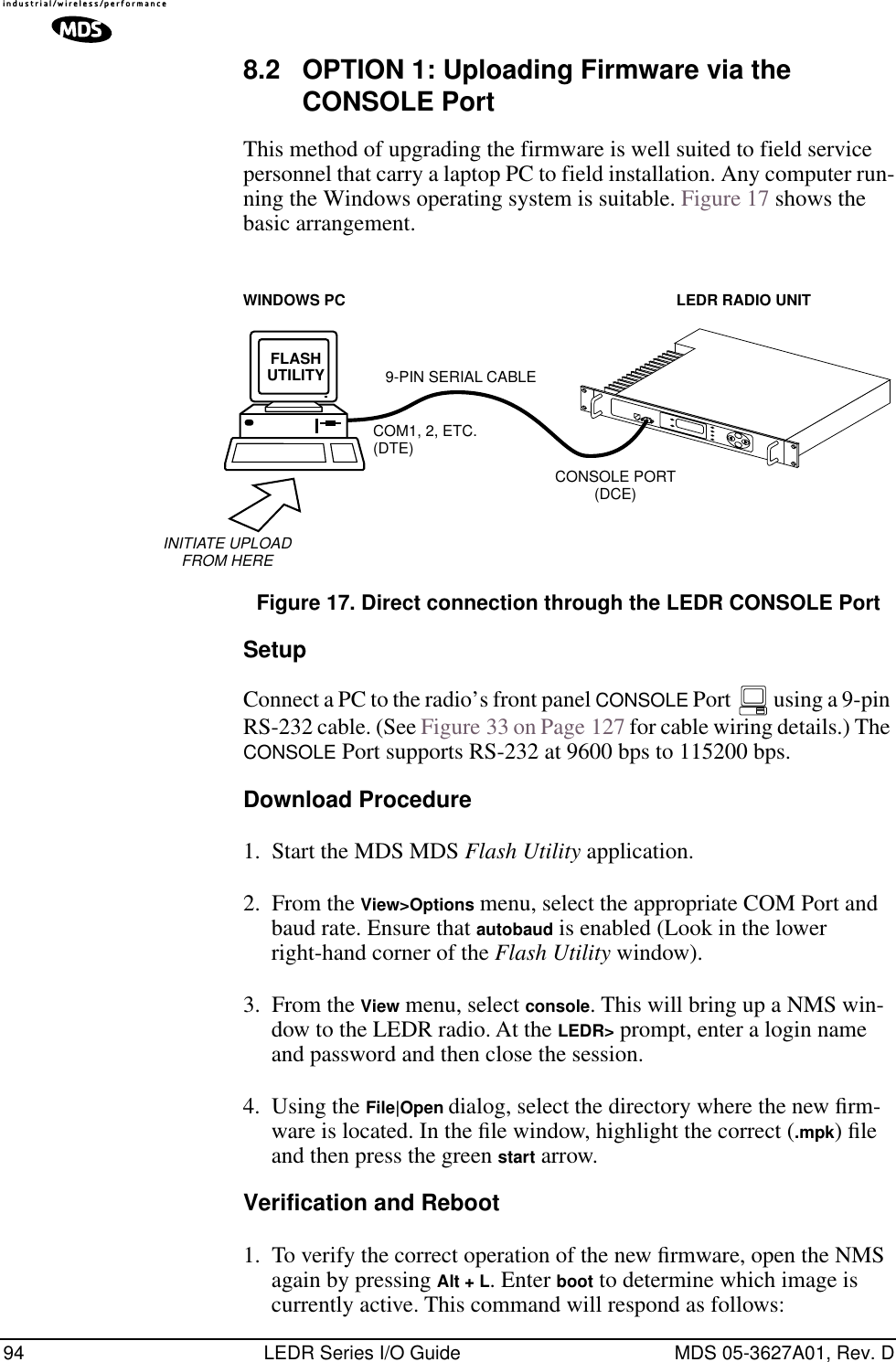
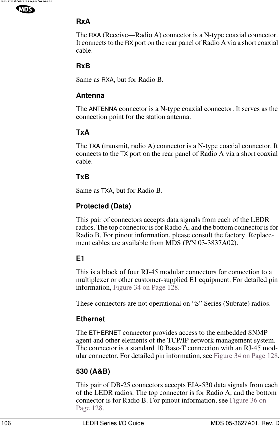
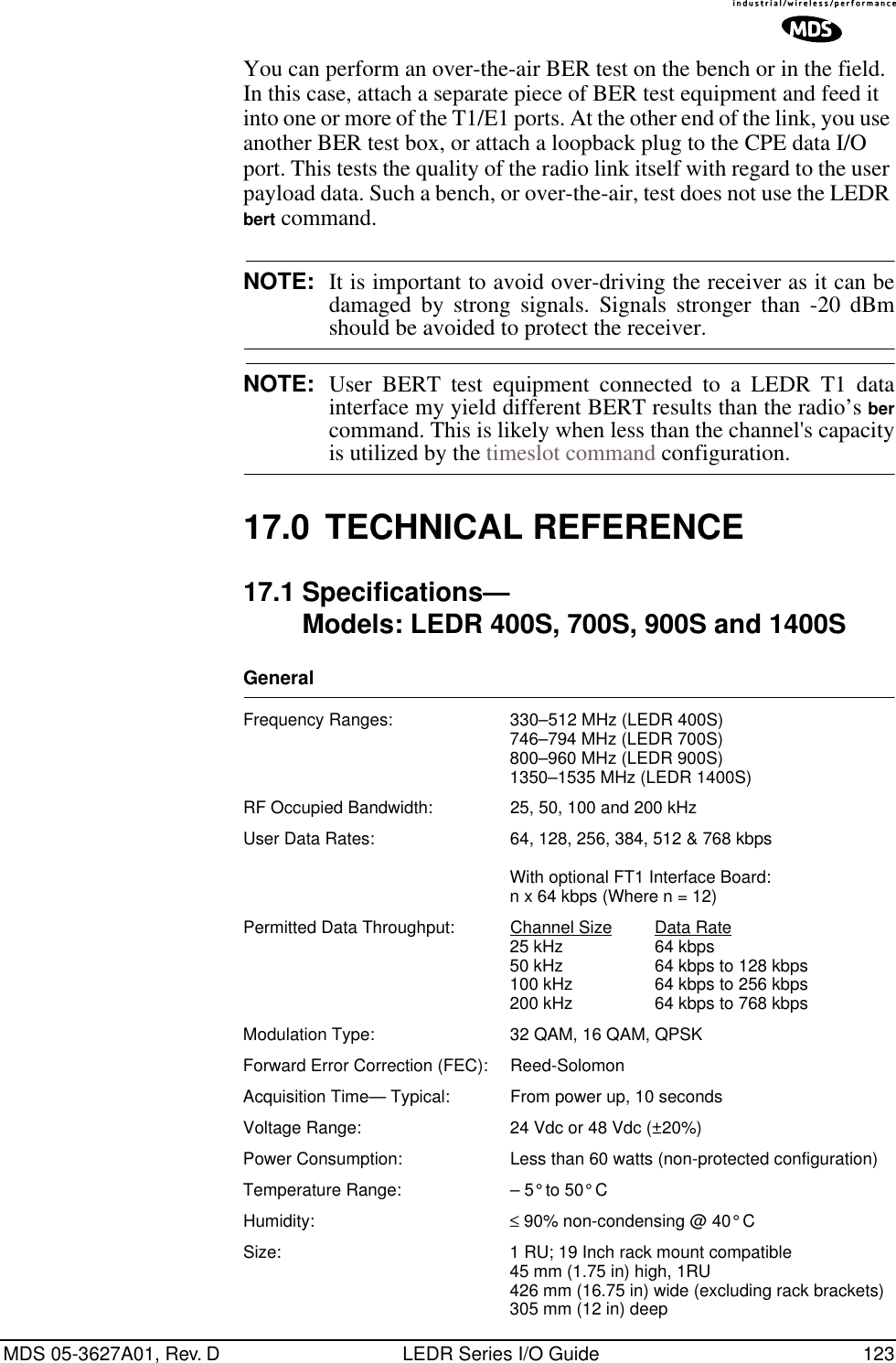
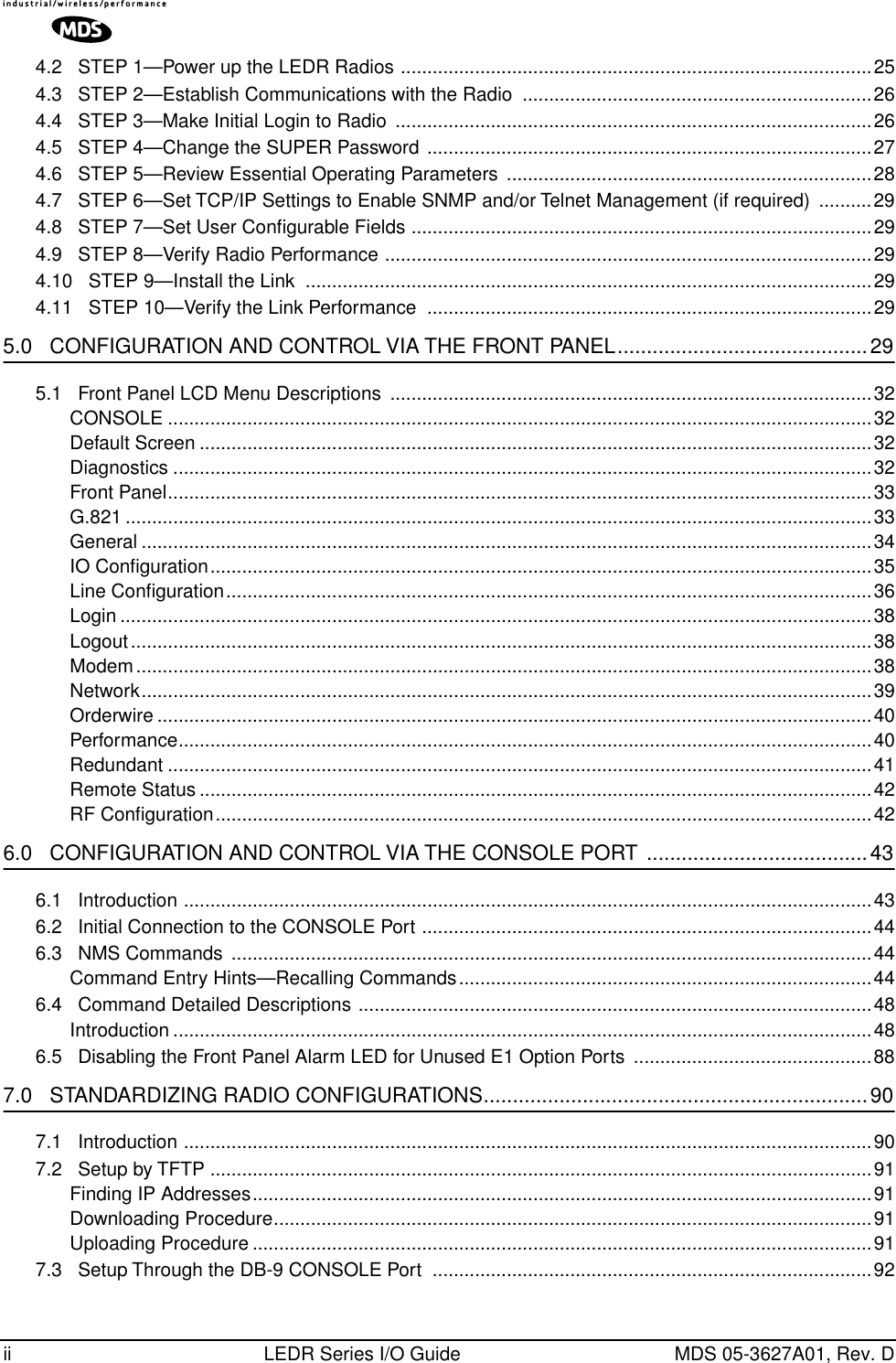
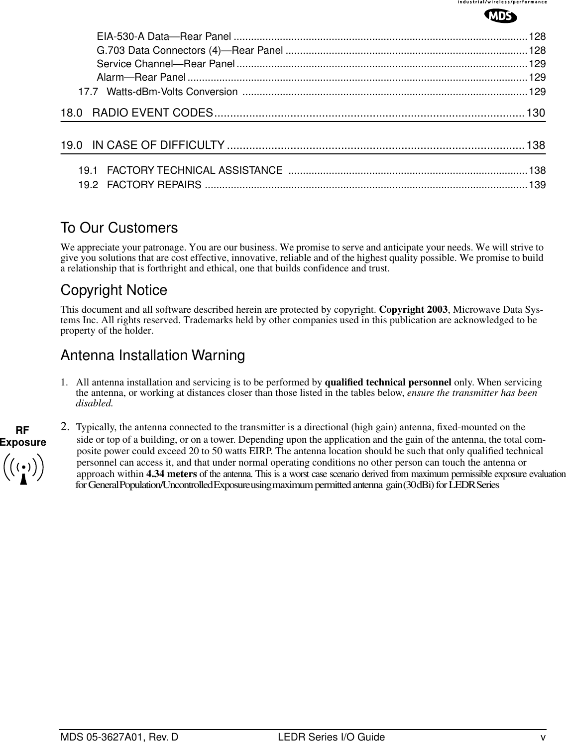
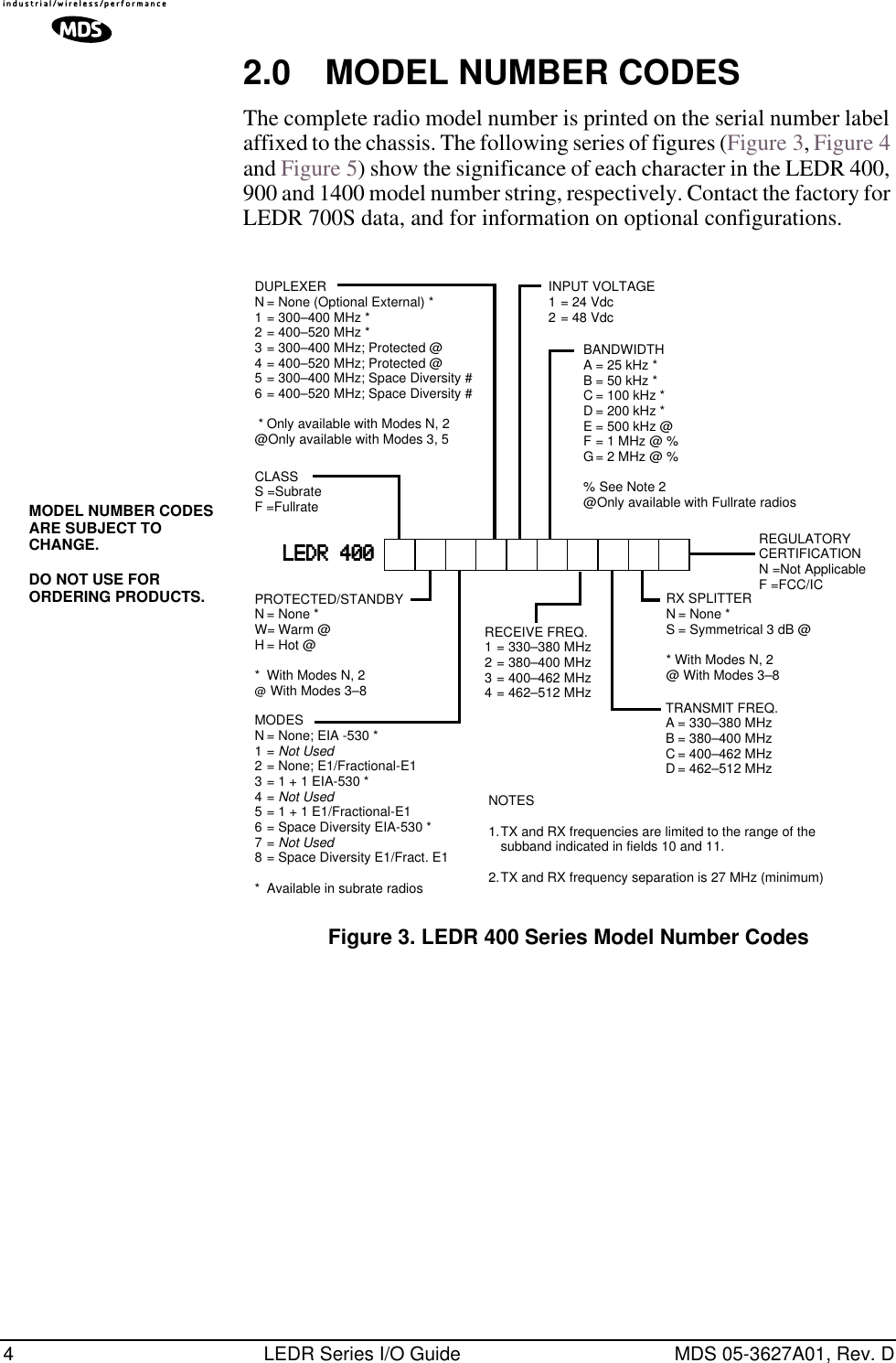
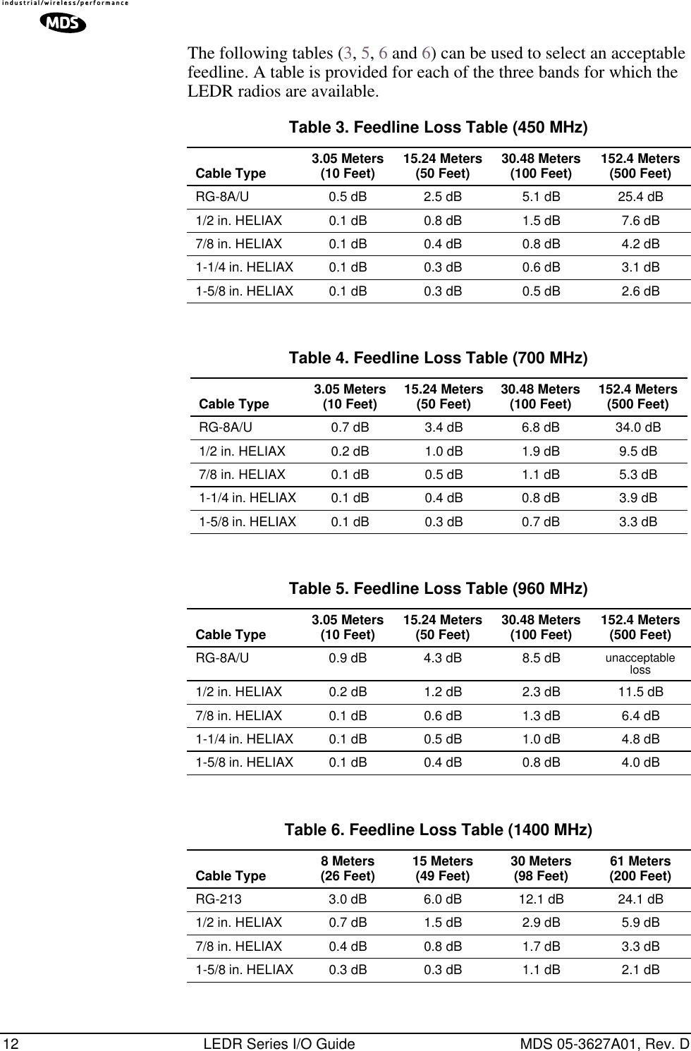
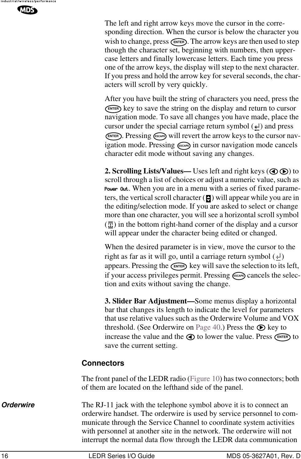
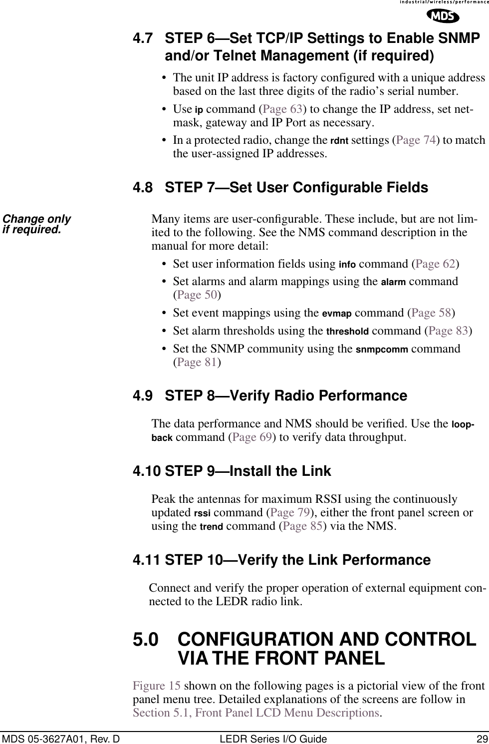
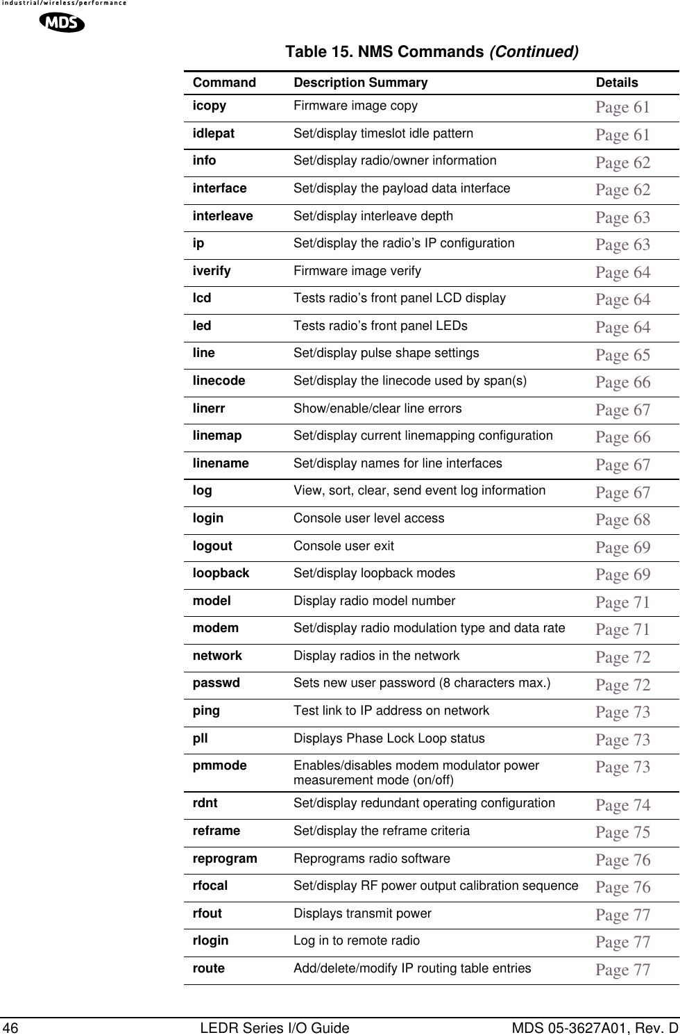
![96 LEDR Series I/O Guide MDS 05-3627A01, Rev. DInvisible place holderFigure 18. Direct connection through the LEDR ETHERNET PortSetup1. Connect the PC’s Ethernet interface to the radio’s ETHERNET Port using a Category 5 Ethernet cross-over cable.2. Copy the file LEDR firmware image file (ledr.mpk) into a known directory on your PC. For example, c:\windows\LEDR\Firmware V2.5\. This directory path will be used later by the TFTP server.Download Procedure1. Launch the MDS TFTP Server on a PC connected to the LEDR radio’s ETHERNET Port through a cross-connect cable.2. Point the TFTP server to the directory from which you desire to upload the new firmware. In the SNMP TFTP server, you should execute the set root command and point to the known directory where ledr.mpk has been copied.3. Launch your Telnet application and login to the radio which you desire to load (reprogram) the firmware image file.4. Determine the active (firmware) image from which you are currently executing by typing boot. The new firmware will downloaded into the inactive image. 5. Execute the command reprogram network ledr.mpk [IP address]. In the command, in place of [IP address], you should actually type the IP address of the TFTP server. For example, reprogram network ledr.mpk 192.168.1.2& TELNET ETHERNETPORTINITIATE UPLOADFROM HERELEDR RADIO UNITLOCAL WINDOWS PCW/FIRMWARE FILESETHERNETPORTLEDR> REPROGRAM NETWORK FILENAME.MPK 192.168.X.B(CHECK STATUS: LEDR> REPROGRAM STATUS)IP ADDRESS: 192.168.X.BCROSS-OVER CABLEIP ADDRESS: 192.168.X.WTFTPSERVER](https://usermanual.wiki/GE-MDS/DS-LEDR700S/User-Guide-312318-Page-104.png)
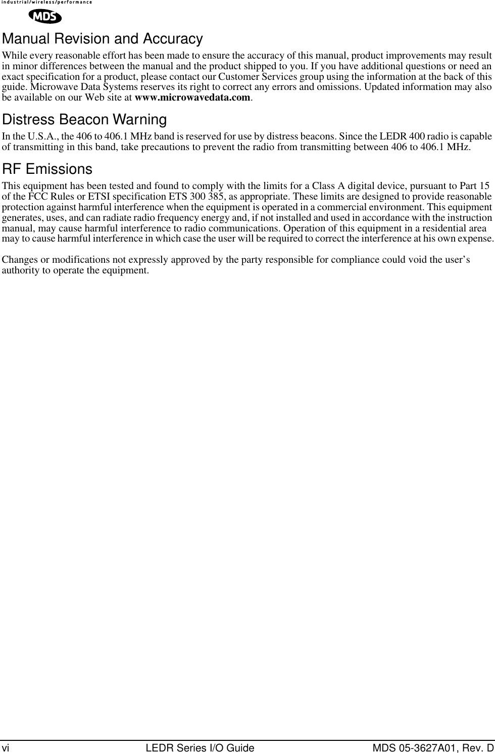
![98 LEDR Series I/O Guide MDS 05-3627A01, Rev. DInvisible place holderFigure 19. Uploading firmware from a remote server via Ethernet Download Procedure1. Start a terminal program, such as HyperTerminal, on the local PC. 2. Log into the LEDR radio using the login command. 3. Use the ip command to ensure that the radio has a valid IP address. 4. Use the ping command from the local PC to ensure that the PC and the radio have valid routes to pass information between them.5. At the radio’s LEDR> prompt, start the download by entering repro-gram network [filename] [source PC’s IP Address]. The download can be monitored from the radio by entering reprogram status. When the download is complete the radio will sound two short beeps and the response from reprogram status will indicate that the download has finished.SNMP Option The TFTP download process can also be initiated using an SNMP man-ager. The Firmware|FwProgTable object provides a means for specifying the TFTP server IP address and the filename for the firmware.TFTPSERVER ETHERNETPORT9-PIN SERIALCABLECONSOLE PORT(DCE)INITIATE UPLOADFROM HERELEDR RADIO UNITREMOTE PCW/FIRMWARE FILES HUB/LAN/WAN/MANTCP/IPETHERNETPORTCOM1, 2, ETC.(DTE)TERMPROG.LEDR> REPROGRAM NETWORK FILENAME.MPK 192.168.X.B(CHECK STATUS: LEDR> REPROGRAM STATUS)IP ADDRESS: 192.168.X.BIP ADDRESS: 192.168.X.WLOCAL WINDOWS PC](https://usermanual.wiki/GE-MDS/DS-LEDR700S/User-Guide-312318-Page-106.png)
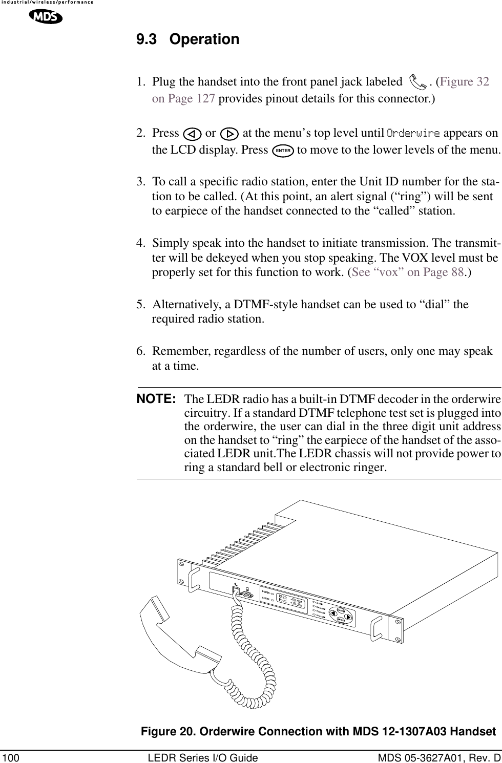
![102 LEDR Series I/O Guide MDS 05-3627A01, Rev. DWhen you set up a system, you must be careful to avoid an infinite loop. If echo is enabled, then every character that enters the Service Channel port will be echoed back out the port. When echo is disabled then data that comes in the Service Channel port is not sent back out the port. Trouble may arise if the device that is connected to the Service Channel also echoes the data it sends. In that case, the device will send characters into the Service Channel Port, the radio will echo the characters back to the device, the device will consider the echoed data to be input which it will in turn echo back to the radio, etcetera, until an overflow condition occurs.You must also set the communication parameters (baud rate, stop bits, char length, and parity) via the svch subcommands so that the settings match those at the device connected to the Service Channel Port.Lastly, the user can re-initialize the Service Channel port via the svch reset command. This may be helpful in the case where an infinite loop overflow condition has locked the port.10.3 UsageThe Service Channel supports ASCII data transfer over the network in broadcast fashion. As a result, devices connected to the Service Channel Ports of different radios will appear to have a transparent half-duplex connection between them. 10.4 NMS CommandsThis command is used to set/display Service Channel parameters.Usage: svch [subcommand] [<argument>] Subcommands: baudcharechooffoffonparityresetstopon—Enable the Service Channeloff—Disable the Service Channelreset—Re-initialize the Service Channelecho—on/offbaud—300, 600, 1200, 2400, 4800 and 9600char— 5, 6, 7, 8 (ASCII character length in bits)parity—none, even, oddstop—1, 2 (Stop bits)](https://usermanual.wiki/GE-MDS/DS-LEDR700S/User-Guide-312318-Page-110.png)