GE MDS DS-MERCURY900 Mercury 900 Wireless Transceiver User Manual Book1
GE MDS LLC Mercury 900 Wireless Transceiver Book1
UserManual.wiki
>
GE MDS
>
DS-MERCURY900 User Manual
>
manual pt 1
Contents
1.
manual pt 1
2.
manual pt 2
3.
User Manual 1
4.
User Manual 2
5.
Users Manual Revised 121908 Part 1
6.
Users Manual Revised 121908 Part 2
7.
Users Manual Revised 121908 Part 3
manual pt 1
Navigation menu
Upload a User Manual
Namespaces
Wiki Guide
HTML
PDF
Info
Views
User Manual
Discussion / Help
Navigation
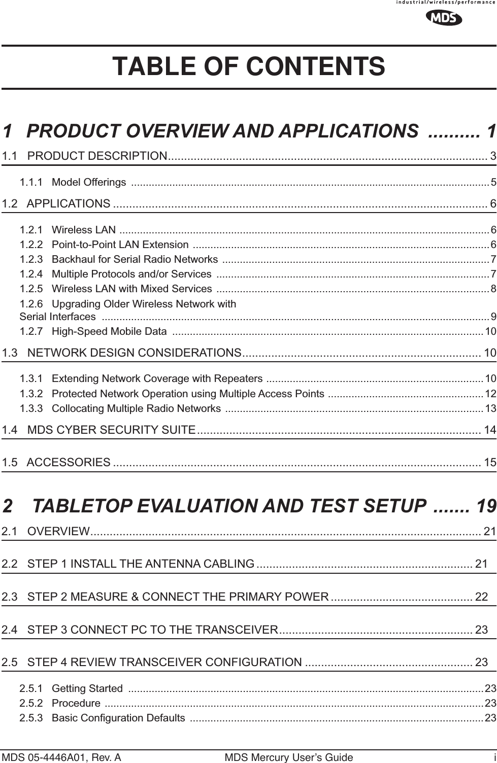
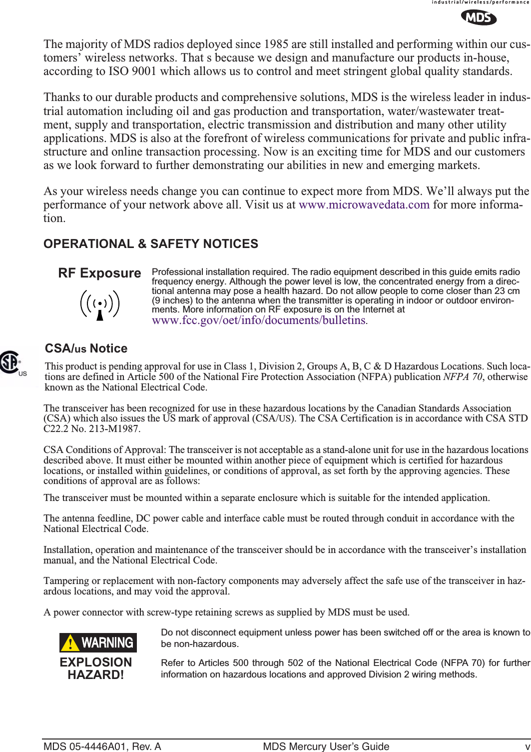

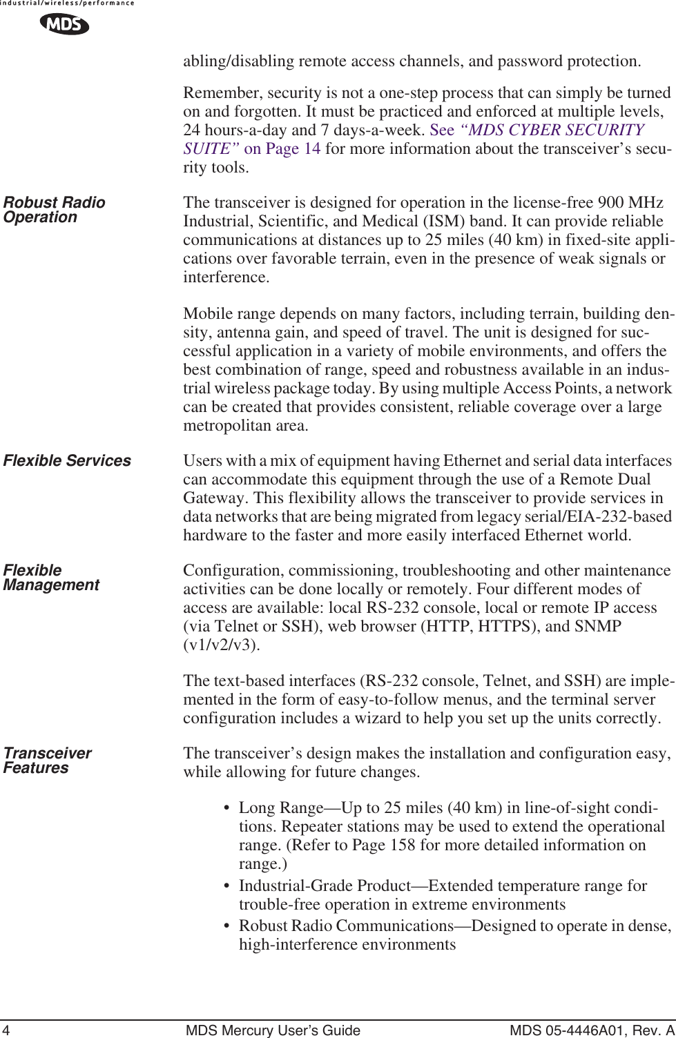
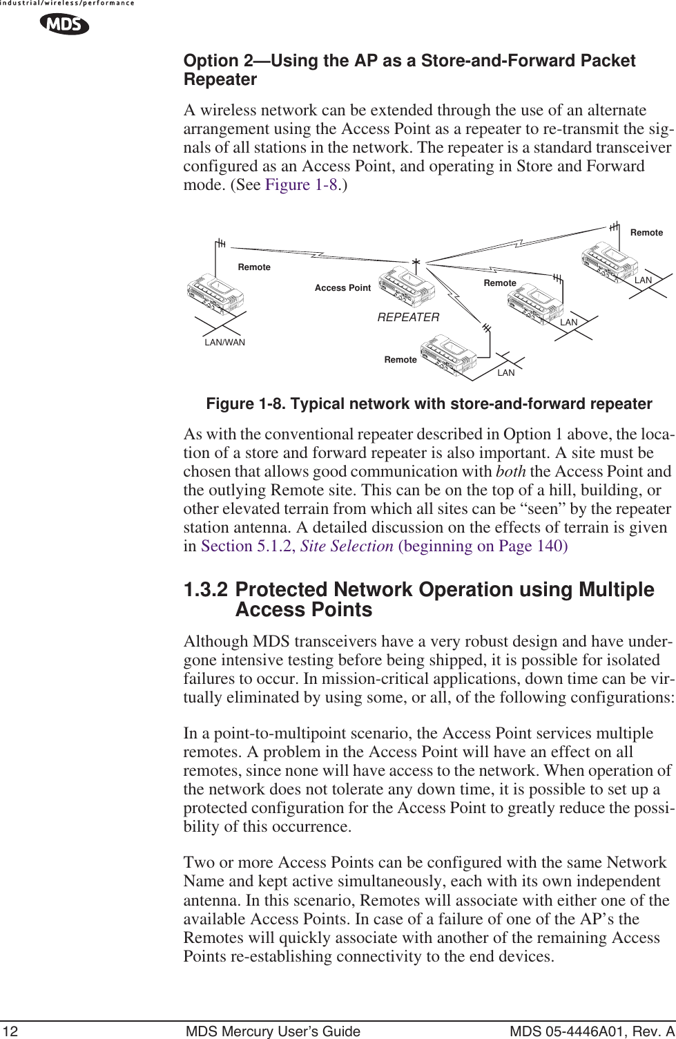


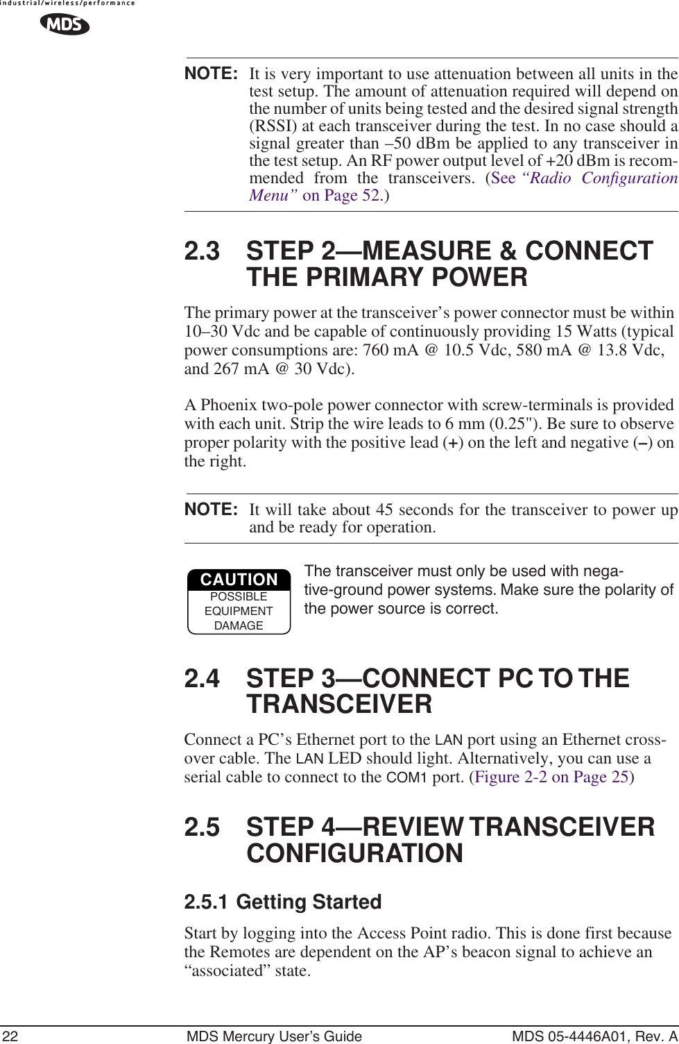
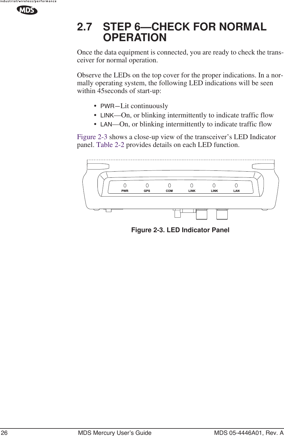

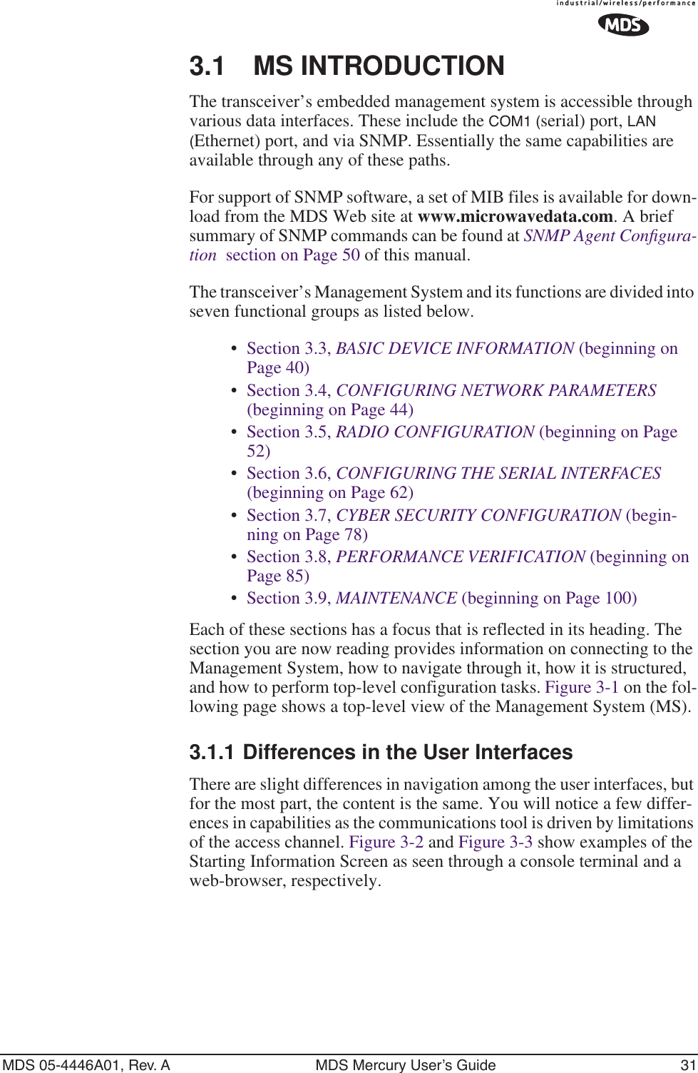
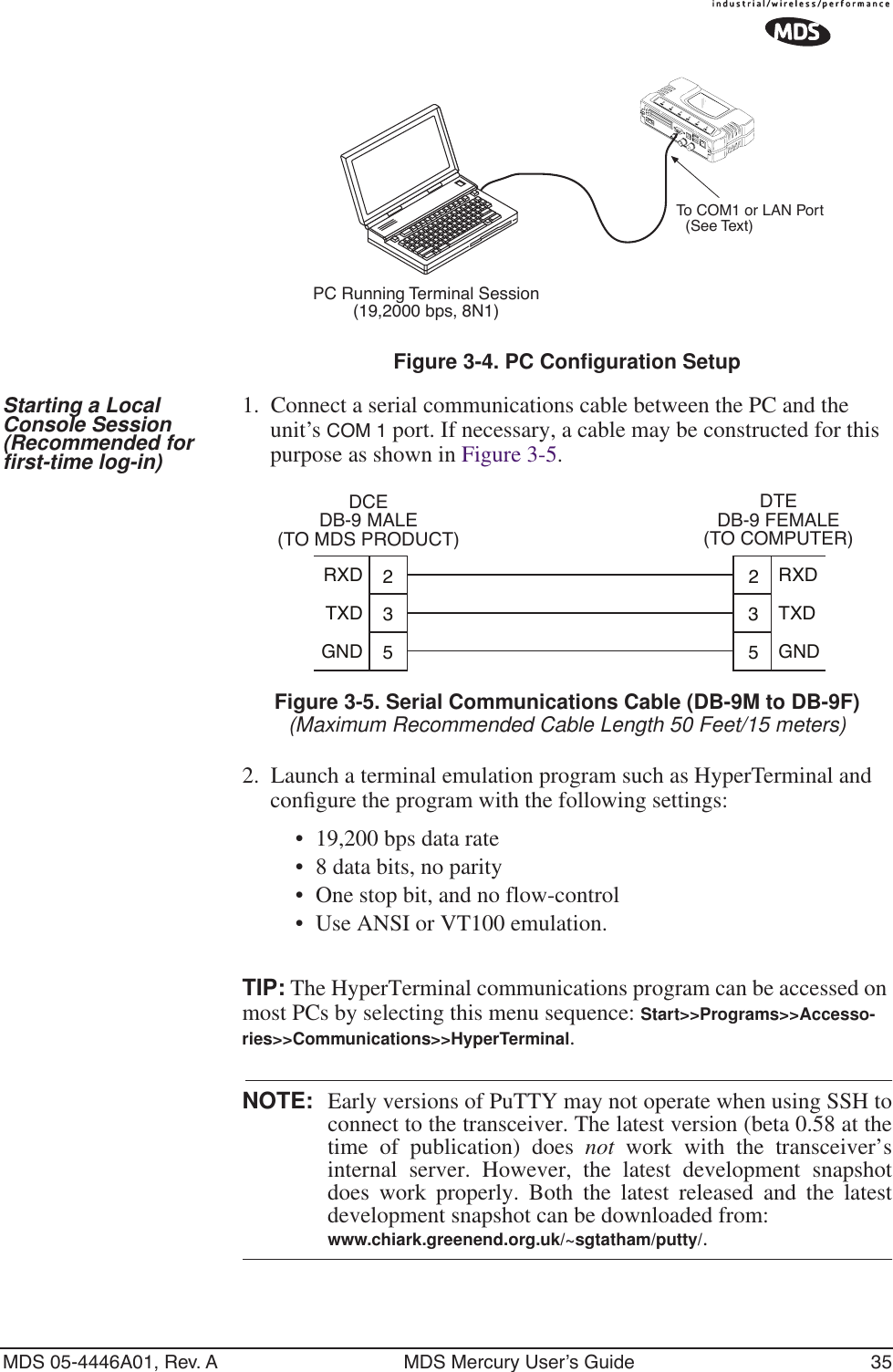
![40 MDS Mercury User’s Guide MDS 05-4446A01, Rev. ANOTE: In the menu descriptions that follow, parameter options/range,and any default values are displayed at the end of the textbetween square brackets. Note that the default setting isalways shown after a semicolon: [available settings or range;default setting]3.3 BASIC DEVICE INFORMATIONThis section contains detailed menu screens and settings that you can use to specify the behavior of the unit.3.3.1 Starting Information ScreenOnce you have logged into the Management System, you will be pre-sented with a screen that provides an overview of the transceiver and its current operating condition. It provides an array of vital information and operating conditions. Figure 3-9. Starting Information Screen•Device Mode—Current operating mode of the unit as it relates to the radio network.•Device Name—This is a user-defined parameter that will appear in the heading of all pages.(To change it, see Network Configuration Menu on Page 44.)•Network Name—The name of the radio network in which the unit is associated.•IP Address—Unit’s IP address [192.168.1.1]•Device Status—Condition of the unit’s association with an Access Point. At the Access Point:•Alarmed—A alarm event has been logged and not cleared.•Operational—Unit operating normally.At a Remote:](https://usermanual.wiki/GE-MDS/DS-MERCURY900.manual-pt-1/User-Guide-703663-Page-48.png)
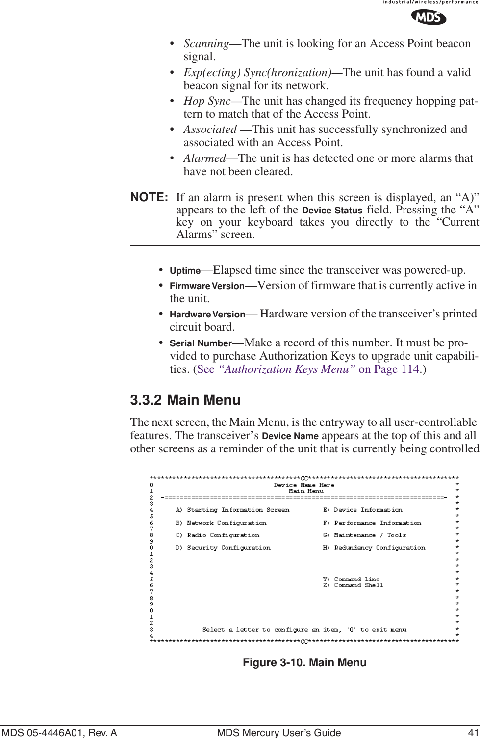
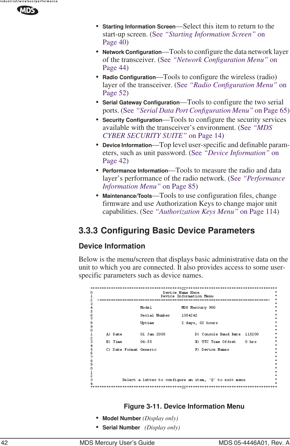
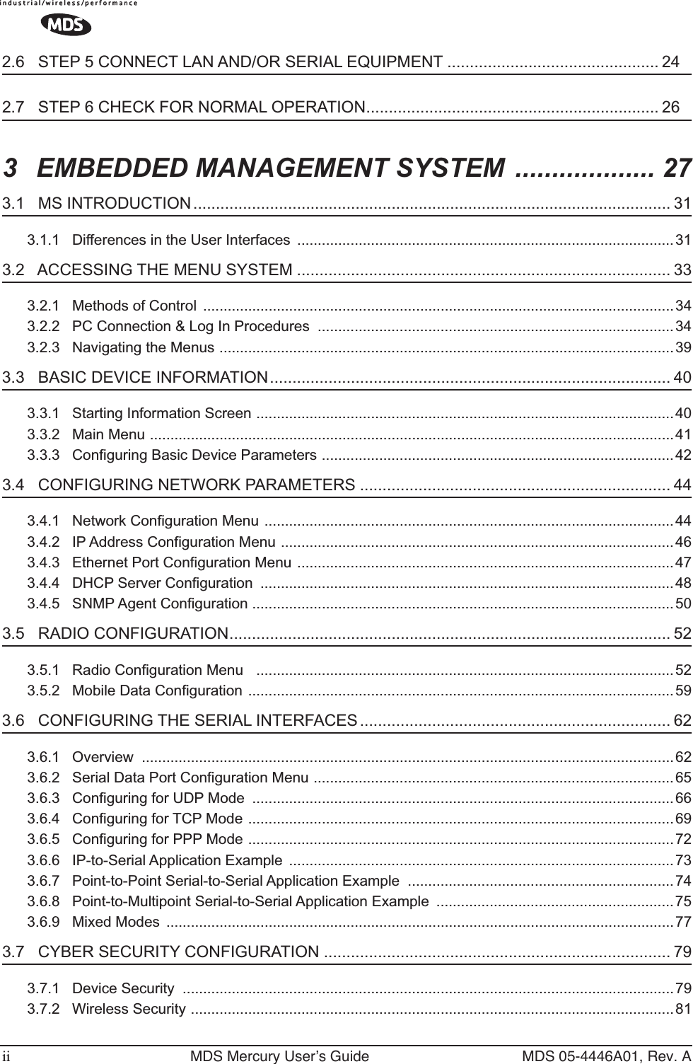
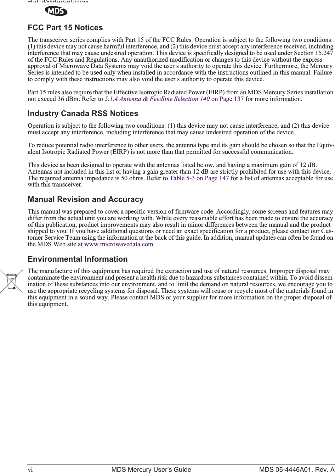
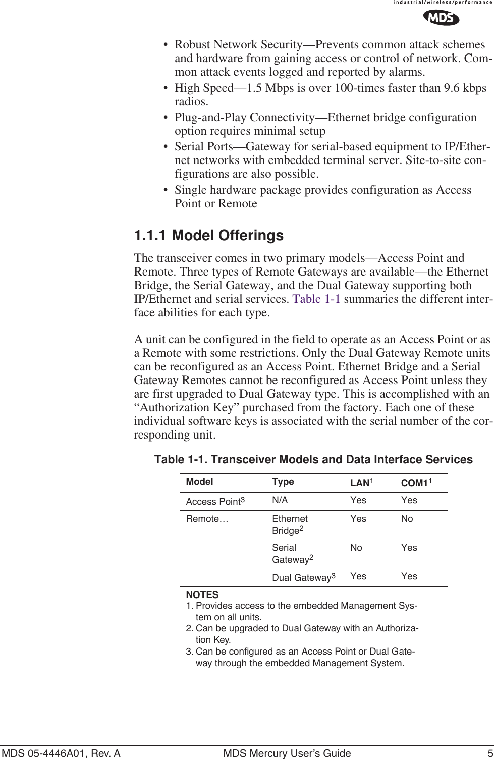
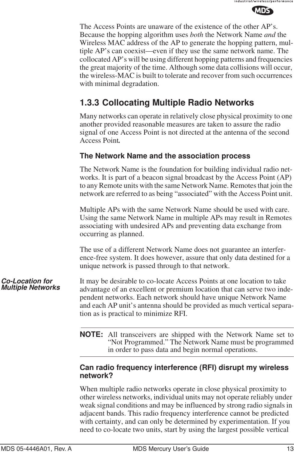
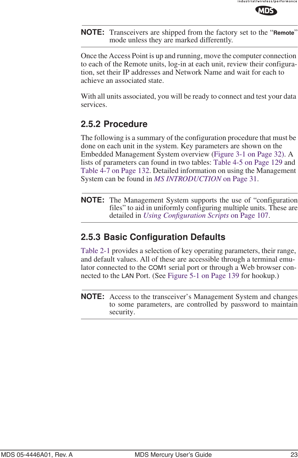
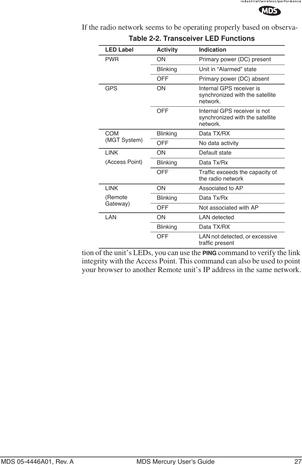
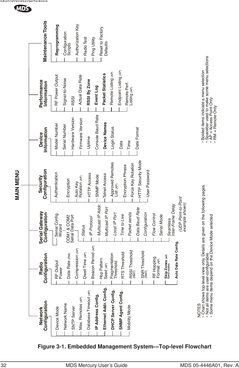
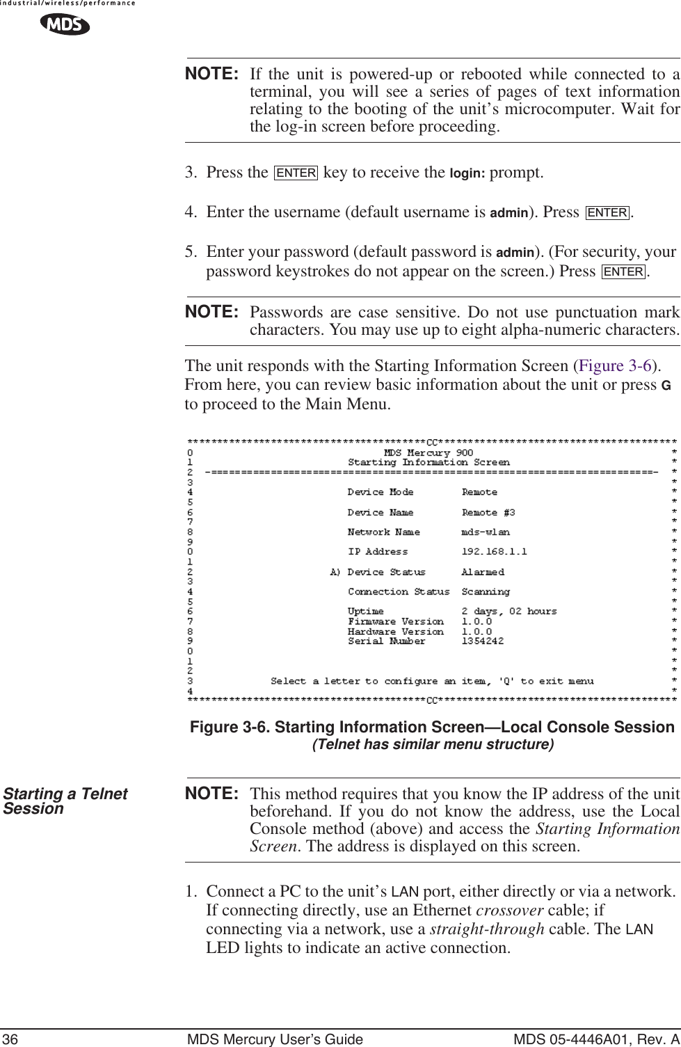
![MDS 05-4446A01, Rev. A MDS Mercury User’s Guide 43•Hardware Version (Display only)•Firmware Version (Display only)—Current firmware installed and being used by the transceiver.•Uptime (Display only)—Elapsed time since powering up.•Console Baud Rate—Used to set/display data communications rate (in bits-per-second) between a connected console terminal and the radio. [19200]•Device Names Menu—Fields used at user’s discretion for general administrative purposes. The Device Name field is used by the transceiver as the “Realm” name for network security and in the MS screen headings. (See Figure 3-12 on Page 43)•Date—Current date being used for the transceiver logs. User-set-able. (Value lost with power failure if SNTP (Simple Network Time Protocol) server not accessible.) •Time—Current time of day. User-setable. Setting: HH:MM:SS (Value lost with power failure if SNTP server not accessible.)•Date Format—Select presentation format:• Generic = dd Mmm yyyy• European = dd-mm-yyyy• US = mm-dd-yyyyDevice Names MenuFigure 3-12. Device Names Menu•Device Name—Device Name, used by the transceiver as the “Realm” name for network login (web browser only) and menu headings. •Owner—User defined; appears on this screen only.•Contact—User defined; appears on this screen only.•Description—User defined; appears on this screen only.•Location—User defined; appears on this screen only.](https://usermanual.wiki/GE-MDS/DS-MERCURY900.manual-pt-1/User-Guide-703663-Page-51.png)
![MDS 05-4446A01, Rev. A MDS Mercury User’s Guide 45•Device Mode (User Review Recommended)—Either Access Point or a variation of a Remote. [Remote]•Network Name (User Review Required)—Name of the radio network of which this unit will be a part. Essential for association of Remotes to the Access Point in the network. [Not Programmed]TIP: For enhanced security, consider using misspelled words, a combi-nation of letters and numbers, and a combination of upper and lower case letters. Also, the Network Name should be at least nine characters long. This helps protect against sophisticated hackers who may use a database of common words (for example, dictio-nary attacks) to determine the Network Name.•SNTP Server—Address of SNTP server (RFC 2030) from which the transceiver will automatically get the time-of-day startup time. Without an SNTP server, the date and time must be man-ually set. An AP will try to get the time and date from the SNTP server only if an IP address is configured. It will continue to retry every minute until it succeeds. A remote will get the time and date from the SNTP server, if an IP address is configured. Otherwise it gets it from the AP at authentication time. The transceivers use UTC (Universal Time Constant) with a configurable time offset. [0.0.0.0]•IP Address Configuration Presents a menu for configuring the local static IP address of the transceiver. Detailed explanations are provided in the section titled IP Address Configuration Menu on Page 46•Ethernet Port Configuration—Presents a menu for defining the sta-tus of the Ethernet port (enabled or disabled), the Ethernet rate limit, link hardware watch (enabled/disabled), and the Ethernet link poll address. Detailed explanations of this menu are con-tained in Ethernet Port Configuration Menu on Page 47•DHCP Server Config(uration)—Menu for configuration of DHCP services by the Access Point unit. DHCP provides “on-the-fly” IP address assignments to other LAN devices, including MDS Mercury 900 units. [Disabled]•SNMP Config Menu—SNMP configuration parameters.•Mobility Mode—Used to configure whether the transceiver is enabled or disabled for mobility operation. Note that this selec-tion may appear on both Access Point and Remote menus, but it only takes effect when set on Remotes. Additional settings and information for mobility operation are contained in Mobile Data Configuration on Page 59. [enabled, disabled; disabled].•Maximum Remotes (AP Only)—Number of Remotes permitted to be associated with (served by) this Access Point. [50]](https://usermanual.wiki/GE-MDS/DS-MERCURY900.manual-pt-1/User-Guide-703663-Page-53.png)
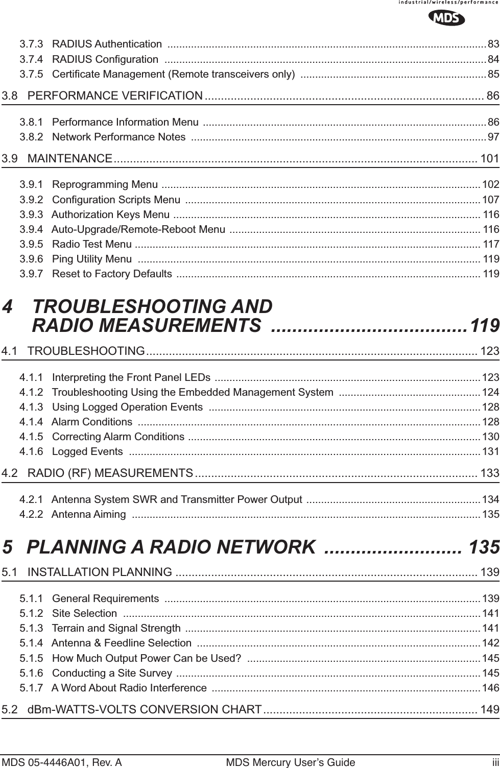
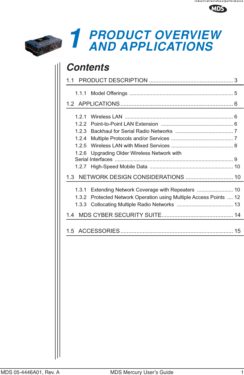
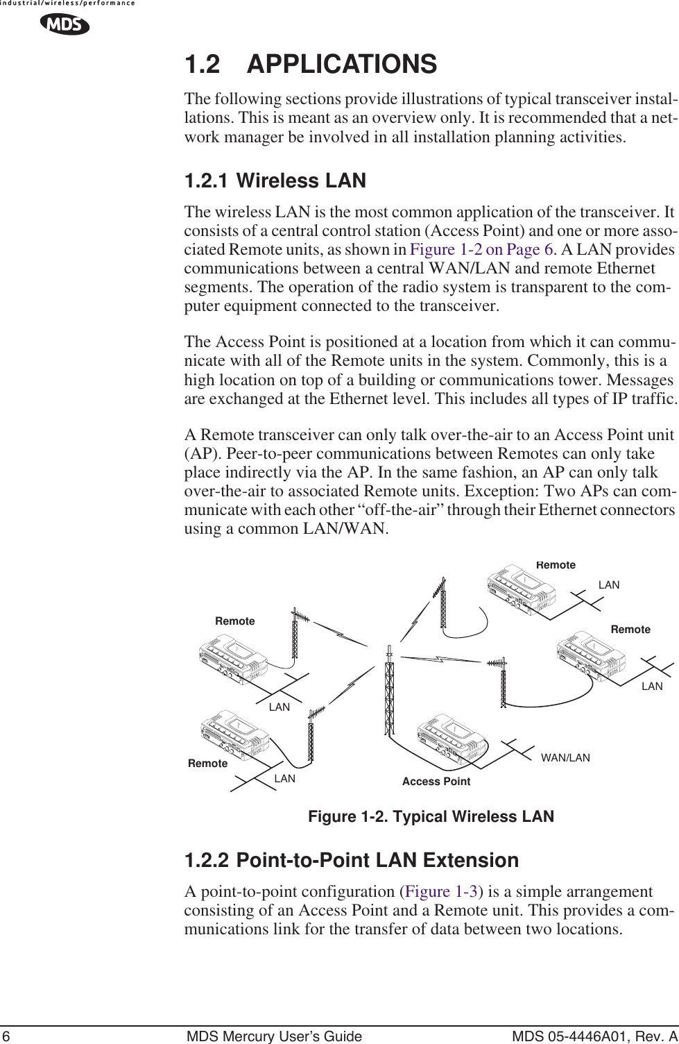
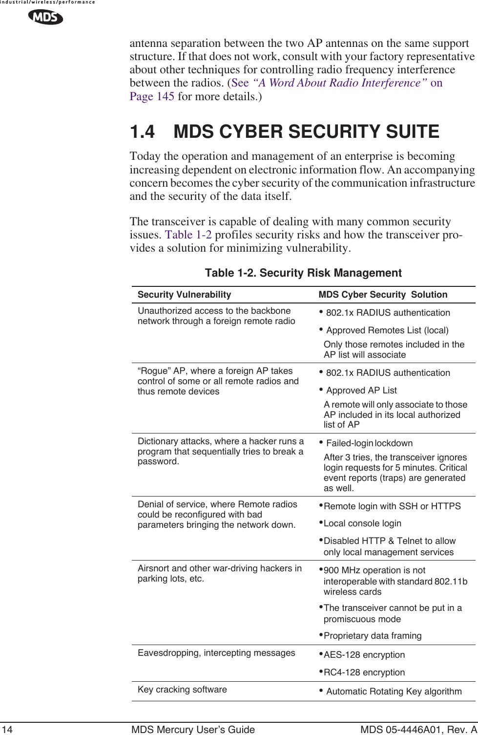
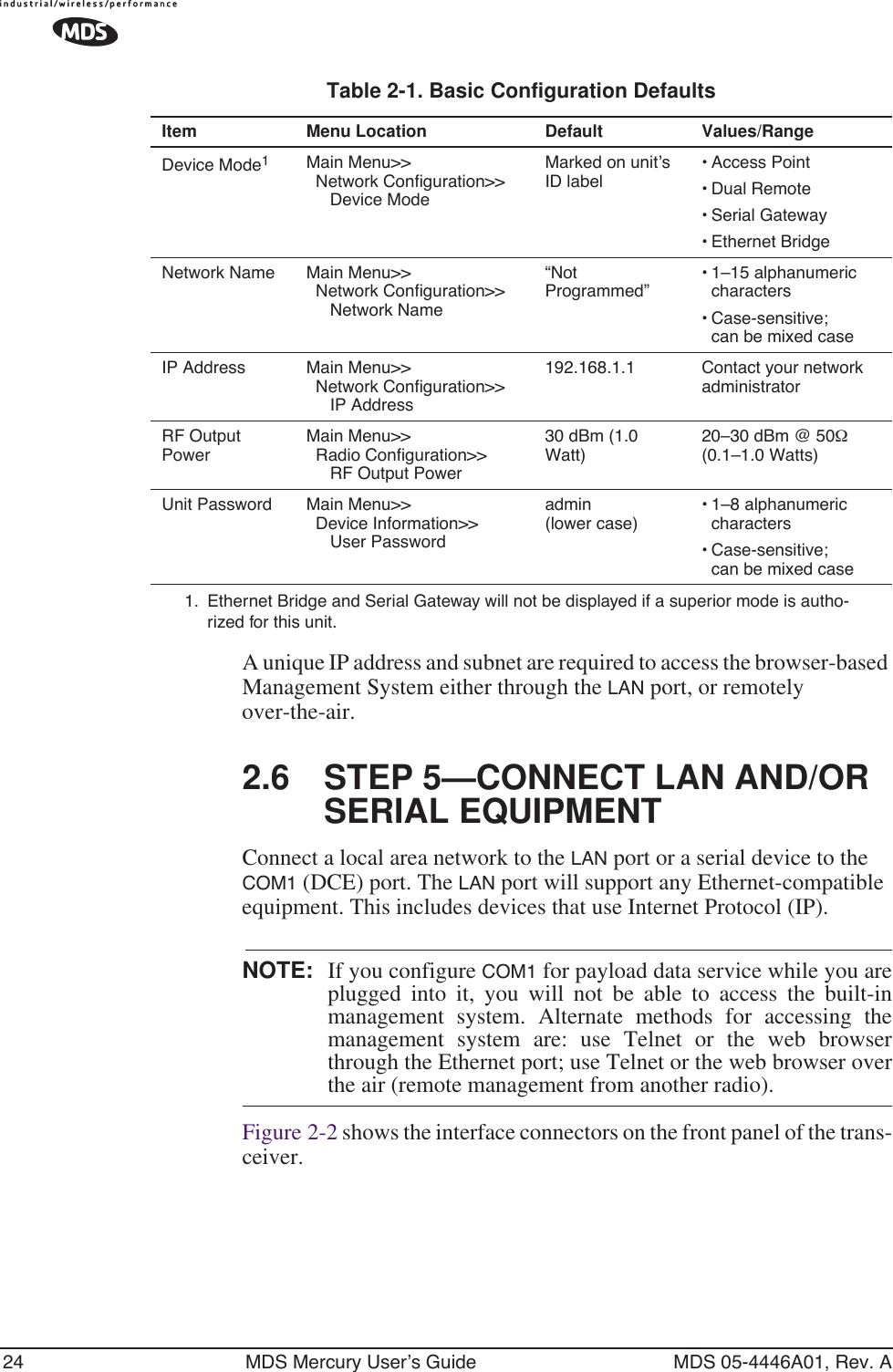
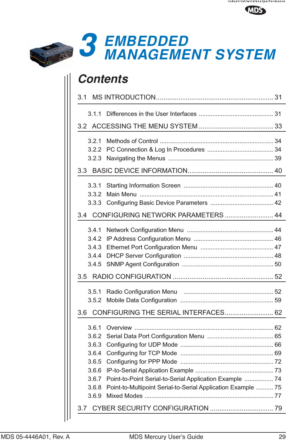
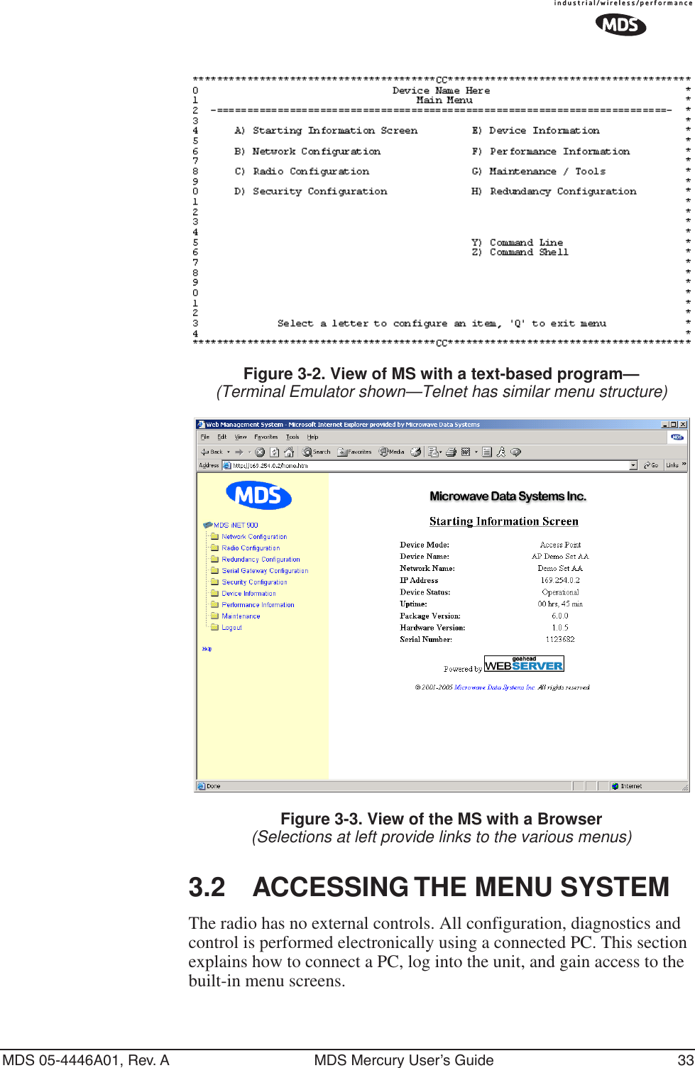
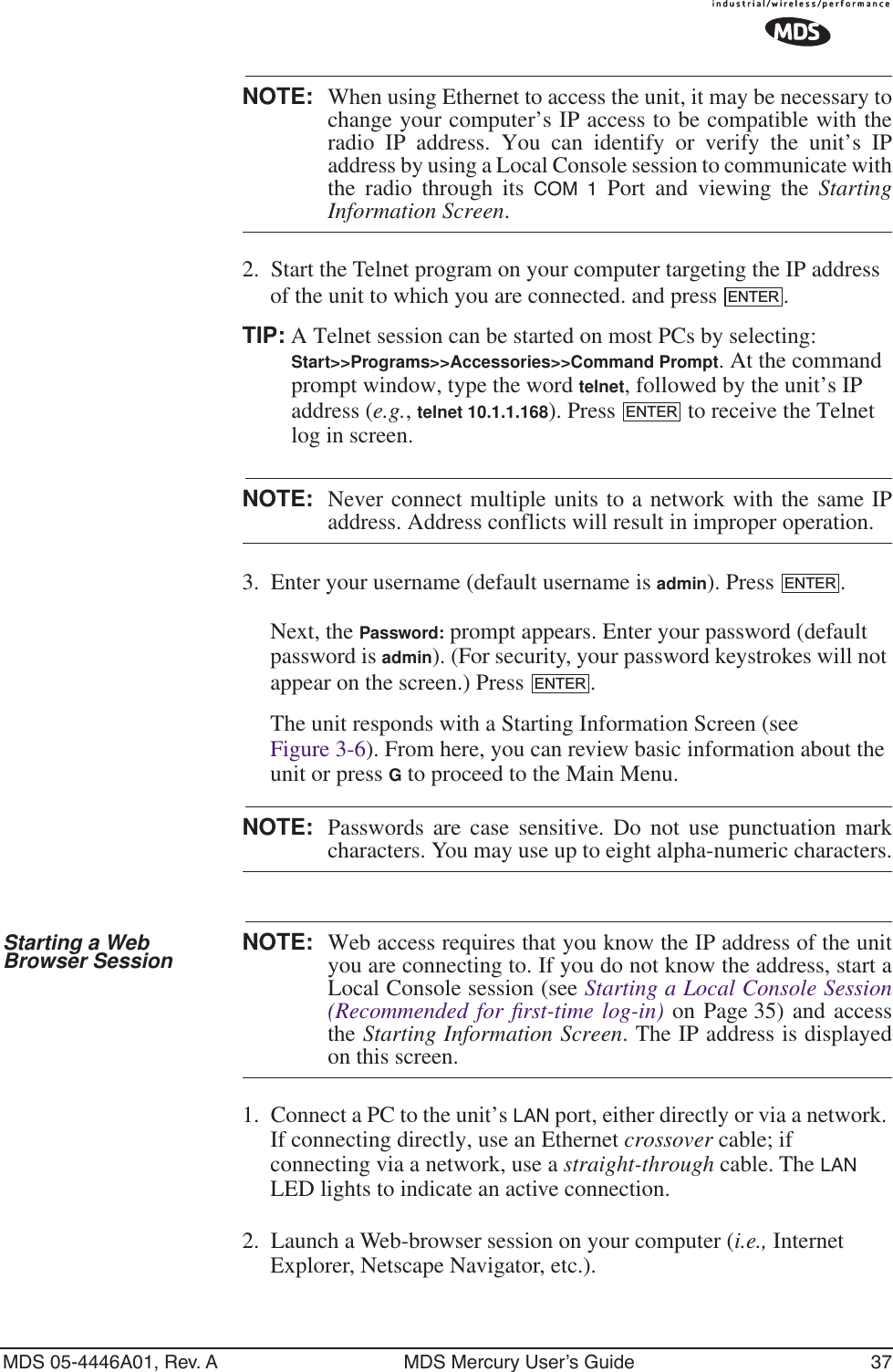
![46 MDS Mercury User’s Guide MDS 05-4446A01, Rev. A•Database Timeout (AP Only)—This sets the database “age time” (Remote Listing Menu (Access Points Only) on Page 93) to determine when a remote is declared as unavailable. The timer may be set from 0 to 255 minutes and resets each time a message is received from a remote. [0–255 minutes; 5 minutes]•Database Logging (AP Only)—Determines which types of devices will be reported as “added” or “deleted” from the AP’s database (See Section 3.8.1, Performance Information Menu (beginning on Page 85). In the case of deletions, this information is trig-gered by a timer expiration as described in the item above. Available selections are: Remote, All (endpoints and remotes), or Disabled.•Ethernet Address (Display Only)—Hardware address of this unit’s Ethernet interface.•Wireless Address (Display Only)—Hardware address of the unit’s wireless interface.3.4.2 IP Address Configuration MenuThe radios use a local IP address to support remote management and serial device services. The IP address of a radio can be set as a static IP address or as a dynamic IP address. When static IP addressing is used, the user must manually configure the IP address and other parameters. When dynamic addressing is used, the radio uses a DHCP Client process to obtain an IP address from a DHCP Server, along with other parame-ters such as a net mask and a default gateway.Figure 3-15. IP Address Configuration Menu](https://usermanual.wiki/GE-MDS/DS-MERCURY900.manual-pt-1/User-Guide-703663-Page-54.png)
![MDS 05-4446A01, Rev. A MDS Mercury User’s Guide 47CAUTION: Changes to any of the following parameters while communicating over the network (LAN or over-the-air) may cause a loss of communication with the unit being configured. Commu-nication will need to be re-established using the new IP address.•IP Address Mode—Defines the source of the IP address of this device. [Static, Dynamic; Static]•Dynamic Mode—Enabling this option forces the transceiver (AP or Remote) to obtain an IP address from any DHCP server avail-able on the LAN. Dynamic Mode is also known as DHCP Client mode. [Disabled]•Static IP Address (User Review Recommended)—Essential for con-nectivity to the transceiver’s MS via the LAN port and to send Ethernet data over the network. Enter any valid IP address that will be unique within the network. [192.168.1.1]This field is unnecessary if DHCP is enabled. [255.255.0.0]Static IP Netmask—The IPv4 local subnet mask. This field is unnecessary if DHCP is enabled. [255.255.0.0]•Static IP Gateway—The IPv4 address of the network gateway device, typically a router. This field is unnecessary if DHCP is enabled. [0.0.0.0]The lower three lines of the screen show the actual addressing at the transceiver whether it was obtained from static configura-tion or from a DHCP server.NOTE: Any change made to the above parameters results in theCommit Changes option appearing on screen. This allows all IPsettings to be changed at the same time.3.4.3 Ethernet Port Configuration MenuThe transceiver allows for special control of the Ethernet interface, to allow traffic awareness and availability of the backhaul network for redundancy purposes.NOTE: The transceiver’s network port supports 10BaseT and100BaseT connections. Confirm that your hub/switch iscapable of auto-switching data rates.To prevent excessive Ethernet traffic from degrading perfor-mance, place the transceiver in a segment, or behind routers.](https://usermanual.wiki/GE-MDS/DS-MERCURY900.manual-pt-1/User-Guide-703663-Page-55.png)
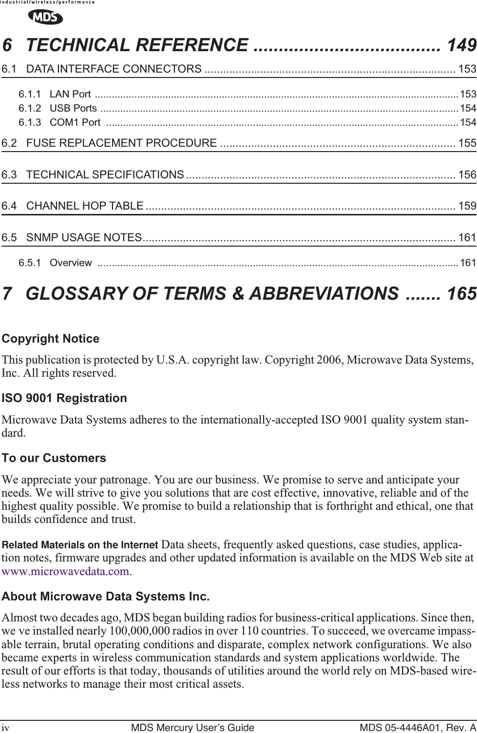
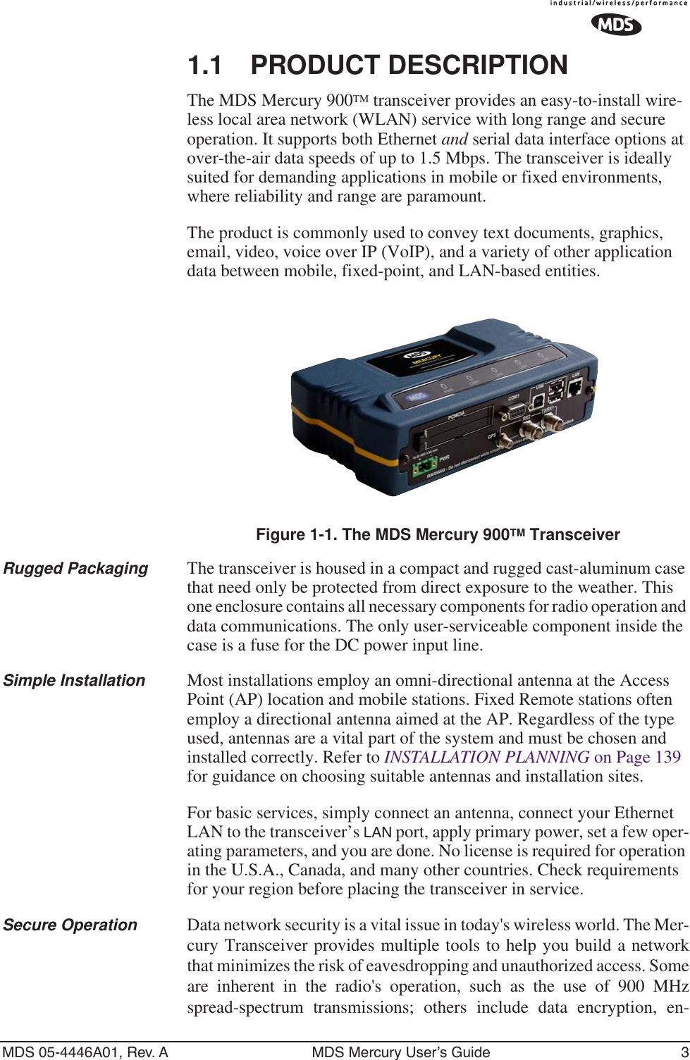
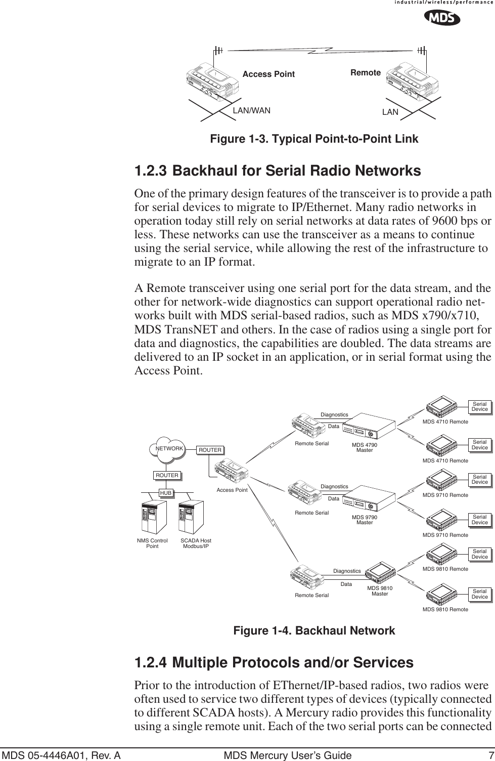
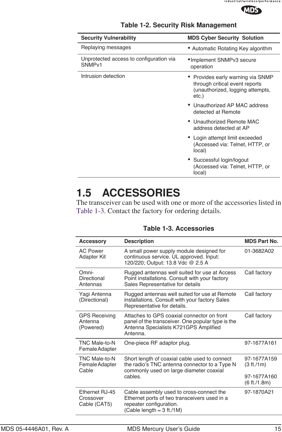
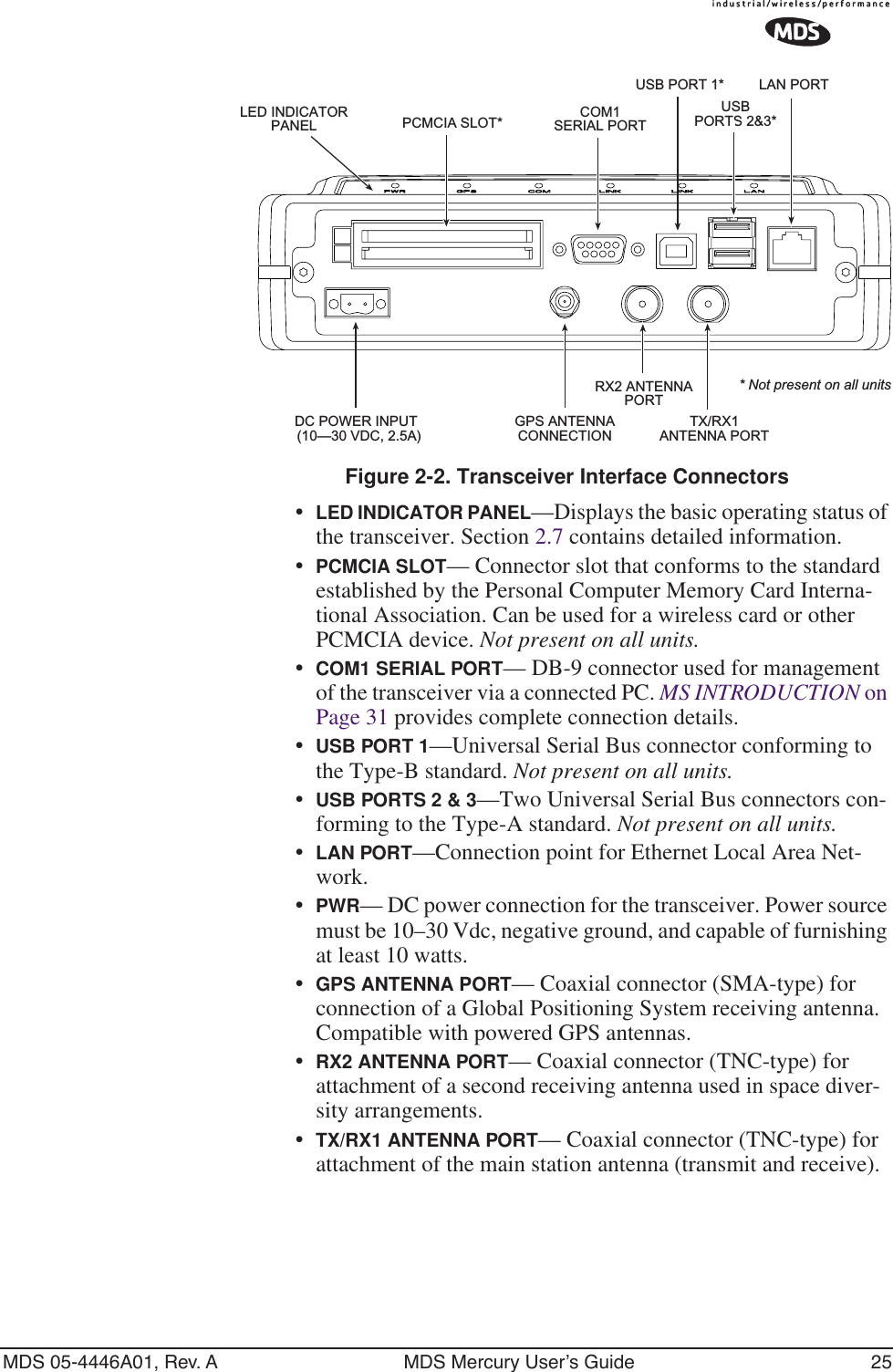
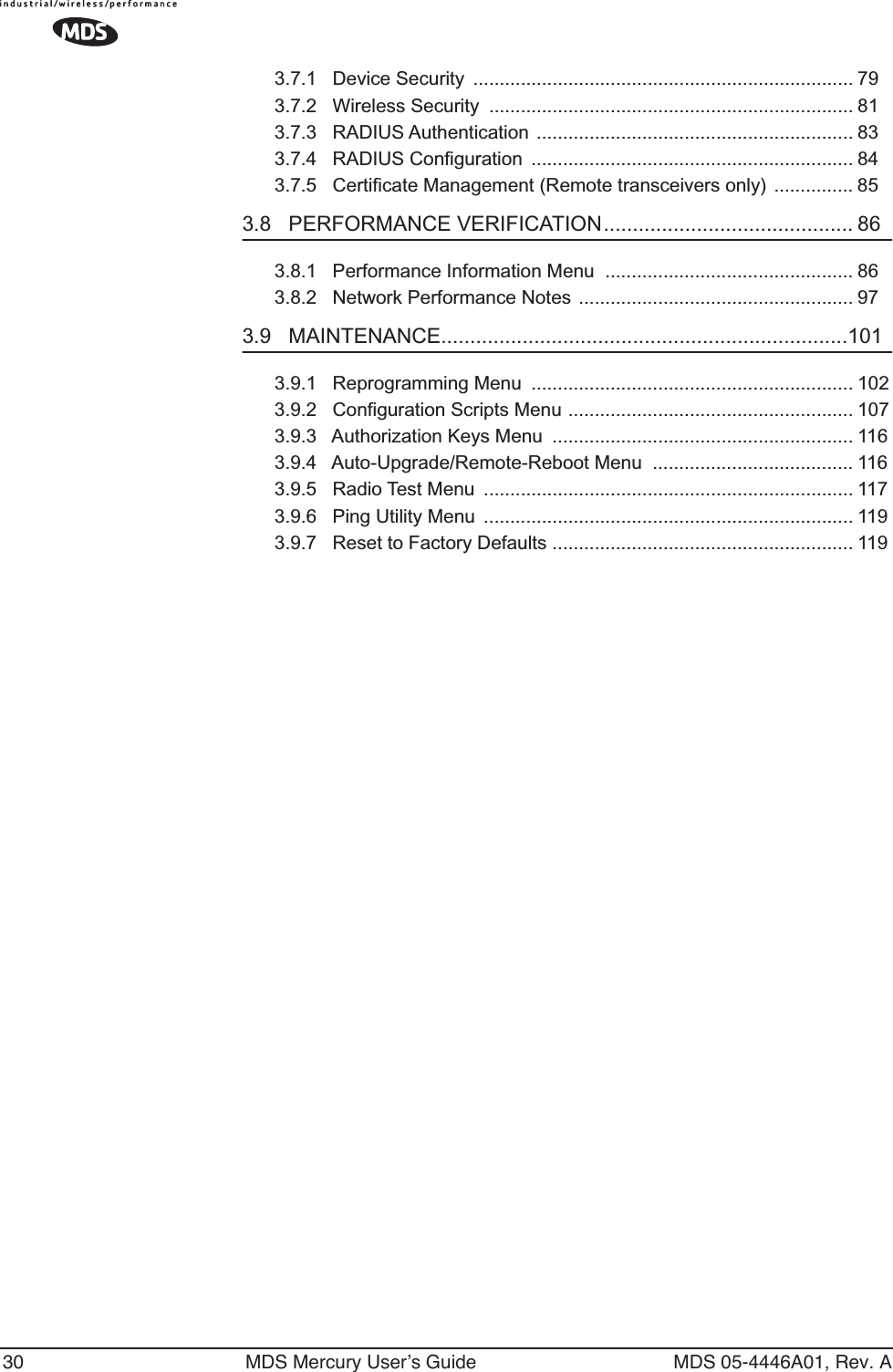
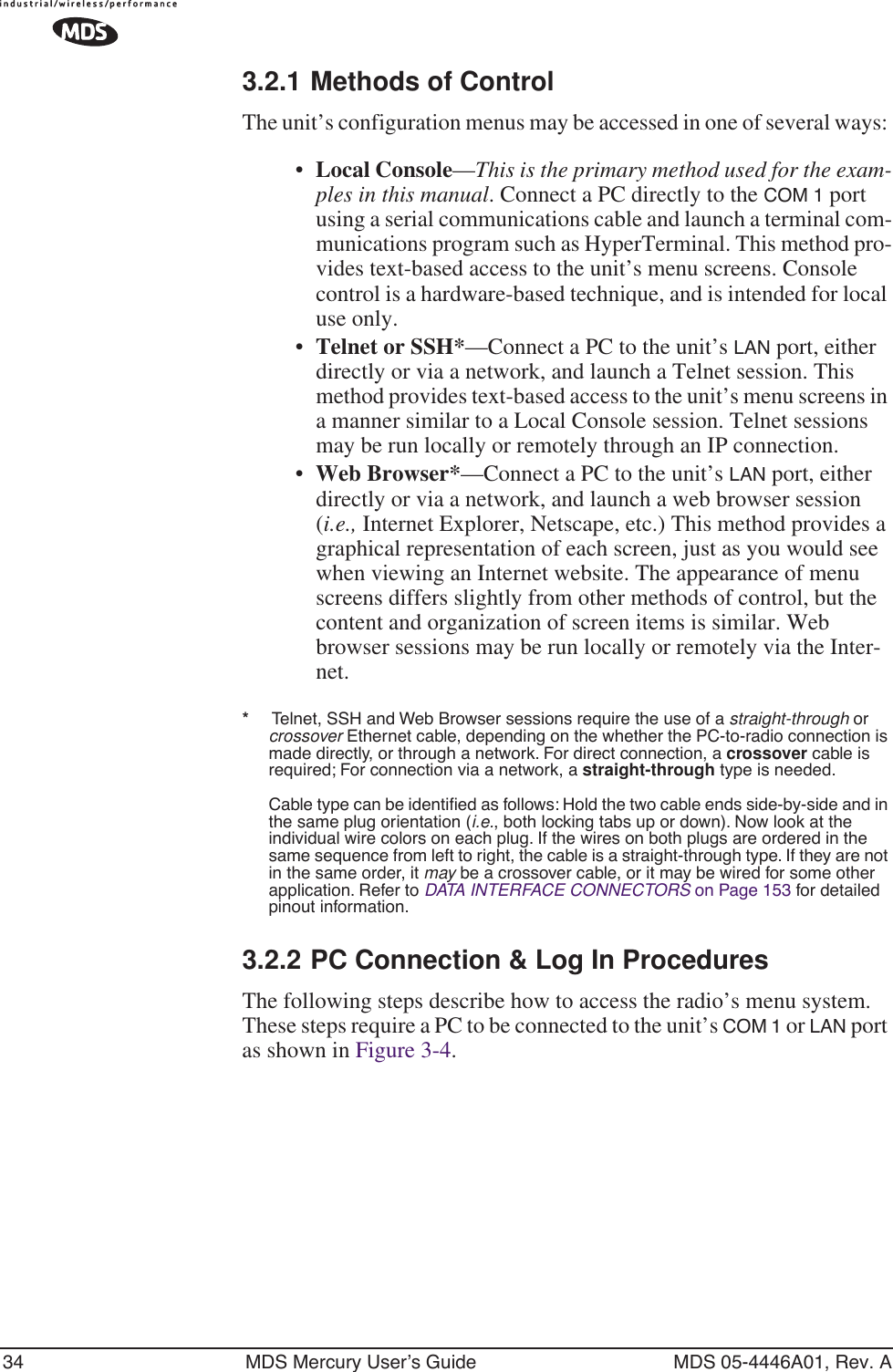
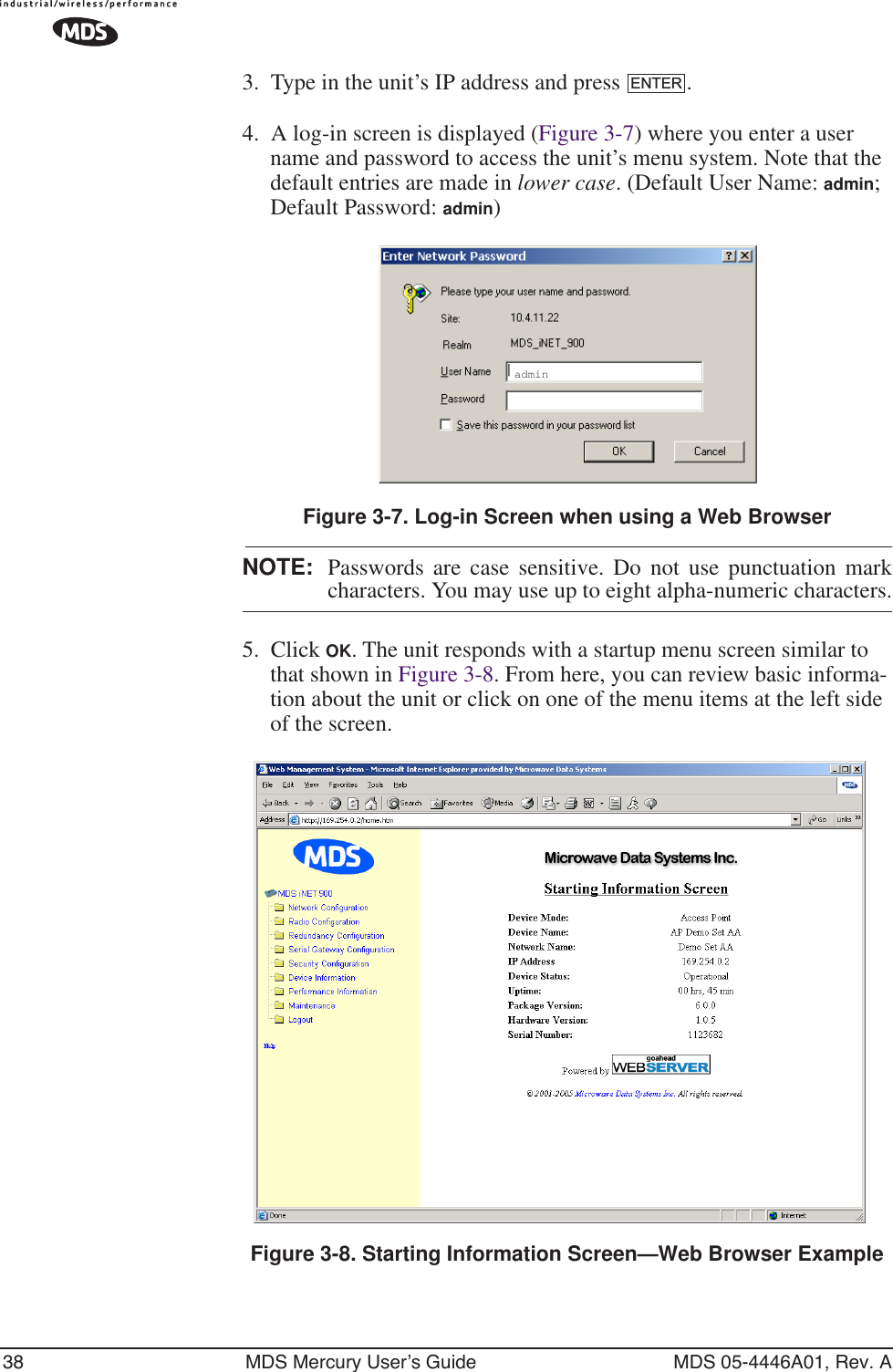
![48 MDS Mercury User’s Guide MDS 05-4446A01, Rev. AFigure 3-16. Ethernet Port Configuration Menu•Ethernet Port Status—Allows enabling/disabling Ethernet traffic for security purposes. Setting it to Follows Link Status enables the port if there is a connection established with the AP, but disables it otherwise. [AP: Enabled, Disabled; Enabled][Remote: Always On, Follow Radio Link, Disabled; Always On]•Ethernet Rate Limit—The transceiver will send alarms (SNMP traps) when the rate reaches 50%, 75%, and 100% to help iden-tify potential problems with traffic.•Ethernet Link (H/W) Watch (AP Only)—Detects the lack of an Ether-net connection to the LAN port at the electrical level (link integ-rity). The current AP will broadcast a beacon signal indicating its “NOT AVAILABLE” status so Remotes that hear it do not try to associate to it. Once the Ethernet connection is restored, this beacon signal changes to “AVAILABLE” and Remotes are allowed to join in. [Disabled]•Ethernet Link Poll Address (AP Only)—When an IP address is pro-vided, the Access Point pings the remote IP device every 2 min-utes to test the integrity of the backhaul link. If this link is not available, the AP will advertise its “NOT AVAILABLE” status in the beacon signal so Remotes do not try to associate to it. Once the IP address is reachable, this beacon signal changes to “AVAILABLE” and Remotes are allowed to join in. 0.0.0.0 dis-ables this function. Any other valid IP address enables it. [0.0.0.0]3.4.4 DHCP Server ConfigurationA transceiver can provide automatic IP address assignments to other IP devices in the network by providing DHCP (Dynamic Host Configura-tion Protocol) services. This service eliminates setting individual device IP address on Remotes in the network, but it still requires thoughtful](https://usermanual.wiki/GE-MDS/DS-MERCURY900.manual-pt-1/User-Guide-703663-Page-56.png)
![MDS 05-4446A01, Rev. A MDS Mercury User’s Guide 49planning of the IP address range. One drawback to network-wide auto-matic IP address assignments is that SNMP services may become inac-cessible as they are dependent on fixed IP addresses.The network can be comprised of radios with the DHCP-provided IP address enabled or with DHCP services disabled. In this way, you can accommodate locations for which a fixed IP address if desired.Figure 3-17. DHCP Server Configuration MenuNOTE: There should be only one DHCP server active in a network. Ifmore than one DHCP server exists, network devices mayrandomly get their IP address from different servers every timethey request one.NOTE: Combining DHCP and RADIUS device authentication mayresult in a non-working radio module if the DHCP server islocated at a remote radio. The DHCP server should be placedat the AP location, if possible.•Server Status—Enable/Disable responding to DHCP requests to assign an IP address. [Disabled/Enabled; Disabled]•DHCP Netmask—IP netmask to be assigned along with the IP address in response to a DHCP request. [0.0.0.0]•Starting Address—Lowest IP address of the range of addresses to be provided by this device. [0.0.0.0]•Ending Address—Highest IP address in the range of addresses to be provided by this device. A maximum of 256 addresses is allowed in this range. [0.0.0.0]•DNS Address—Domain Name Server address to be provided by this service.•WINS Address—Windows Internet Naming Service server address to be provided by this service.](https://usermanual.wiki/GE-MDS/DS-MERCURY900.manual-pt-1/User-Guide-703663-Page-57.png)
![MDS 05-4446A01, Rev. A MDS Mercury User’s Guide 51Invisible place holderFigure 3-18. SNMP Server Configuration MenuFrom Access PointThis menu provides configuration and control of vital SNMP functions. •Read Community String—SNMP community name with SNMPv1/SNMPv2c read access. This string can be up to 30 alpha-numeric characters.•Write Community String—SNMP community name with SNMPv1/SNMPv2c write access. This string can be up to 30 alpha-numeric characters.•Trap Community String—SNMP community name with SNMPv1/SNMPv2c trap access. This string can be up to 30 alpha-numeric characters.•V3 Authentication Password—Authentication password stored in flash memory. This is used when the Agent is managing pass-words locally (or initially for all cases on reboot). This is the SNMPv3 password used for Authentication (currently, only MD5 is supported). This string can be up to 30 alpha-numeric characters.•V3 Privacy Password Privacy password stored in flash memory. Used when the SNMP Agent is managing passwords locally (or initially for all cases on reboot). This is the SNMPv3 password used for privacy (DES encryption). This string can be between 8 and 30 alpha-numeric characters.•SNMP Mode—This specifies the mode of operation of the radio’s SNMP Agent. The choices are: disabled, v1_only, v2_only, v3_only. v1-v2, and v1-v2-v3. If the mode is disabled, the Agent does not respond to any SNMP traffic. If the mode is v1_only, v2_only, or v3_only, the Agent responds only to that version of SNMP traffic. If the mode is v1-v2, or v1-v2-v3, the Agent responds to the specified version of SNMP traffic. [v1-v2-v3]](https://usermanual.wiki/GE-MDS/DS-MERCURY900.manual-pt-1/User-Guide-703663-Page-59.png)
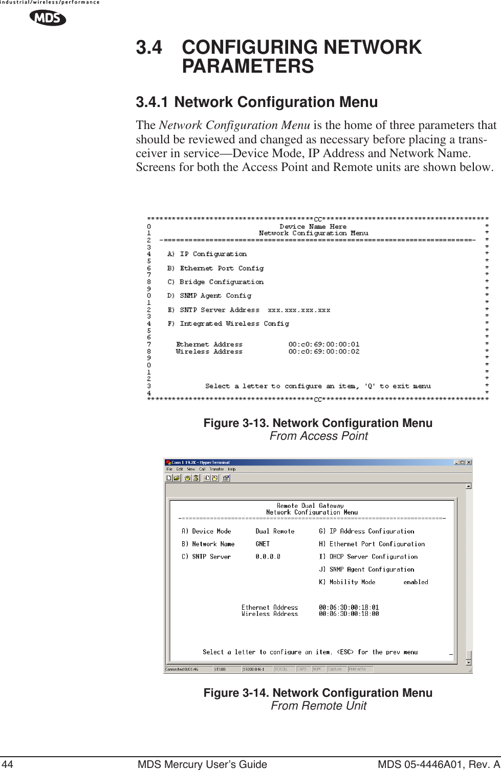
![52 MDS Mercury User’s Guide MDS 05-4446A01, Rev. A•Trap Version—This specifies what version of SNMP will be used to encode the outgoing traps. The choices are v1_traps, v2_traps, and v3_traps. When v3_traps are selected, v2-style traps are sent, but with a v3 header. [v1 Traps, v2 Traps, v3 Traps]•Auth Traps Status—Indicates whether or not traps will be gener-ated for login events to the transceiver. [Disabled/Enabled; Dis-abled]•SNMP V3 Passwords—Determines whether v3 passwords are managed locally or via an SNMP Manager. The different behav-iors of the Agent depending on the mode selected, are described in SNMP Mode above.•Trap Manager #1–#4— Table of up to 4 locations on the network that traps are sent to. [Any standard IP address]NOTE: The number in the upper right-hand corner of the screen is theSNMP Agent’s SNMPv3 Engine ID. Some SNMP Managersmay need to know this ID in order interface with the trans-ceiver’s SNMP Agent. The ID only appears on the screenwhen SNMP Mode is either v1-v2-v3 or v3_only.3.5 RADIO CONFIGURATIONThere are two primary data layers in the transceiver network—radio and data. Since the data layer is dependent on the radio layer working prop-erly, configuration of the radio items should be reviewed and set before proceeding. This section explains the Radio Configuration Menu, (Figure 3-19 for AP, Figure 3-20 for Remote). The Configuration Menu is followed a secondary menu, the Skip Zone Options.3.5.1 Radio Configuration Menu Figure 3-19. Radio Configuration Menu From Access Point](https://usermanual.wiki/GE-MDS/DS-MERCURY900.manual-pt-1/User-Guide-703663-Page-60.png)
![MDS 05-4446A01, Rev. A MDS Mercury User’s Guide 53Figure 3-20. Radio Configuration MenuFrom Remote Unit•RF Output Power (User Review Recommended)—Sets/displays RF power output level. Displayed in dBm. Setting should reflect local regulatory limitations and losses in antenna transmission line. (See “How Much Output Power Can be Used?” on Page 144 for information on how to calculate this value.)[20–30; 20]•Data Rate (Remote Only. AP fixed is at 512/1 Mbps.)—Shows the over-the-air data rate setting for the Remote radio. Remotes can operate at one of two data rates when communicating with an AP; 512 kbps or 1 Mbps. Higher speeds are possible with strong RF signal levels, typically stronger than –77 dBm RSSI includ-ing a 15 dB fade margin.When the data rate is set to AUTO, the remote radio is able to change speeds based on the signal quality criteria set in the Auto Data Rate submenu described later in this section (see Page 56).[256, 512, AUTO; AUTO]•Compression (AP Only)—Enabling this option uses LZO com-pression algorithm for over-the-air data. Varying levels of data reduction are achieved depending on the nature of the informa-tion. Text files are typically the most compressible, whereas binary files are the least compressible. On average, a 30% increase in throughput can be achieved with compression enabled.•Dwell Time—Duration (in milliseconds) of one hop on a particu-lar frequency in the hopping pattern. (This field is only change-able on an Access Point. Remotes get their value from AP upon association.) [8.2, 16.4, 32.8, 65.5, 131.1; 32.8]](https://usermanual.wiki/GE-MDS/DS-MERCURY900.manual-pt-1/User-Guide-703663-Page-61.png)
![54 MDS Mercury User’s Guide MDS 05-4446A01, Rev. ATIP: If a packet is being transmitted and the dwell time expires, the packet will be completed before hopping to the next frequency. •Beacon Period—Amount of time between Beacon transmissions (in msec).Available Intervals: Normal (104 ms), Fast (52 ms), Faster (26 ms), Slow (508 ms), Moderate (208 ms). These values provide rel-atively quick association times where Fast is very fast (≈ 5 sec) and the other end, the largest recommended value, the 508 ms period is slow (≈ 60 sec). [Normal, Fast, Faster, Slow, Moderate; Nor-mal]TIP: Increasing the Beacon Period will provide a small improvement in network data throughput. Shortening it decreases the time needed for Remotes to associate with the AP. A short beacon period is usually only a benefit when there are mobile Remotes in the network.•Hop Pattern Seed—A user-selectable value to be added to the hop pattern formula. This is done in the unlikely event that identical hop patterns are used with two collocated or nearby networks. Changing the seed value will minimize the potential for RF-sig-nal collisions in these situations. (This field is only changeable on an Access Point. Remotes read the AP’s value upon associa-tion.) [0 to 255; 1]•Fragment Threshold—Before transmitting over the air, if a packet exceeds this number of bytes, the transceiver sends the packet in multiple fragments that are reassembled before being delivered over the Ethernet interface at the receiving end. Only even num-bers are acceptable entries for this parameter. Over-the-air data fragmentation is not supported on AP units. (See “Network Per-formance Notes” on Page 96 for additional information.) [256–1600 bytes; 1600]TIP: In an interference-free environment this value should be large to maximize throughput. If interference exists then the value should be set to smaller values. The smaller the packet the less chance of it being interfered with at the cost of slightly reduced throughput.•RTS Threshold—Number of bytes for the over-the-air RTS/CTS handshake boundary. (See “Network Performance Notes” on Page 96.) [0 to 1600 bytes; 500]NOTE: While the transceiver accepts RTS Threshold values below100, the lowest value that works is 100.](https://usermanual.wiki/GE-MDS/DS-MERCURY900.manual-pt-1/User-Guide-703663-Page-62.png)
![MDS 05-4446A01, Rev. A MDS Mercury User’s Guide 55TIP: Lower the RTS Threshold as the number of Remotes or overall over-the-air traffic increases. Using RTS/CTS is a trade-off, giving up some throughput in order to prevent collisions in a busy over-the-air network.The RTS Threshold should be enabled and set with a value smaller than the Fragmentation Threshold described above. RTS forces the Remotes to request permission from the AP before sending a packet. The AP sends a CTS control packet to grant permission to one Remote. All other Remotes wait for the specified amount of time before transmitting.•RSSI Threshold (for alarm)—Level (dBm) below which the received signal strength is deemed to have degraded, and a crit-ical event (alarm) is generated and logged. Under these condi-tions, the PWR lamp flashes, and a trap is sent to the trap manager if SNMP is enabled and set properly. [0 to -120; -90]•SNR Threshold (for alarm)—Value (dB) below which the sig-nal-to-noise ratio is deemed to have degraded and a critical event is generated and logged. Under these conditions, the PWR lamp flashes, and a trap is sent to the trap manager if SNMP is enabled and set properly. [0 to 40; Not Programmed]•RF Hopping Format—Operation must be compliant with coun-try-specific restrictions for the frequency band used. This option must be specified when the order is placed and cannot be mod-ified in the field by the user. The available formats are:•ISM: 902–928 MHz band•GSM: 915–928 MHz band•SPLIT: 902-907.5 and 915-928 MHz bands•CHANNELS: 902–928 MHz, selectable, from 1 to 80 channels.NOTE: When using CHANNELS mode, all radios (AP and Remotes)must be set to use the same channels in order to establish a link.If this is not done, the radios will not connect.NOTE: The transceiver operates only in the CHANNELS mode, withselectable channels from 1 to 75. •Channel Config—Brings up a submenu (Figure 3-21) that dis-plays.](https://usermanual.wiki/GE-MDS/DS-MERCURY900.manual-pt-1/User-Guide-703663-Page-63.png)
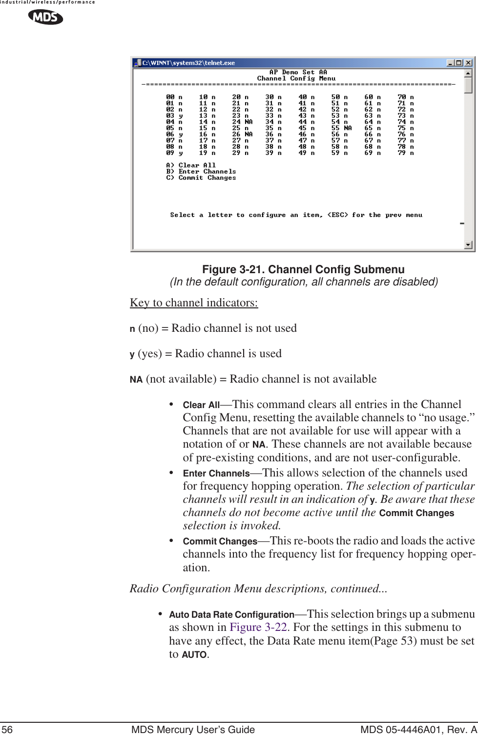
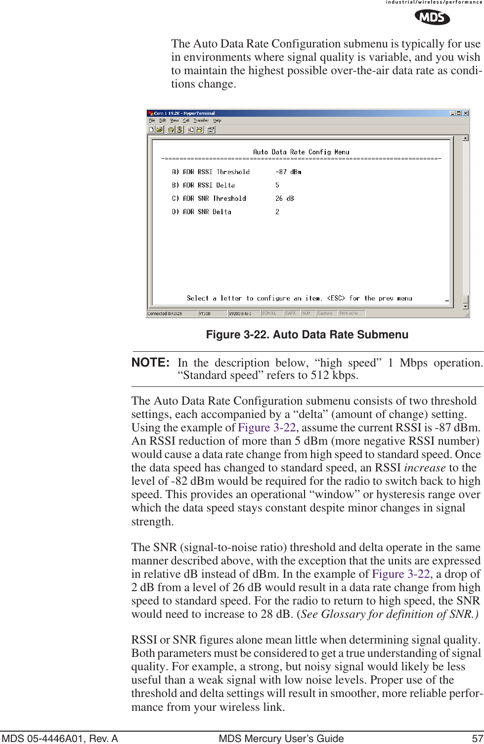
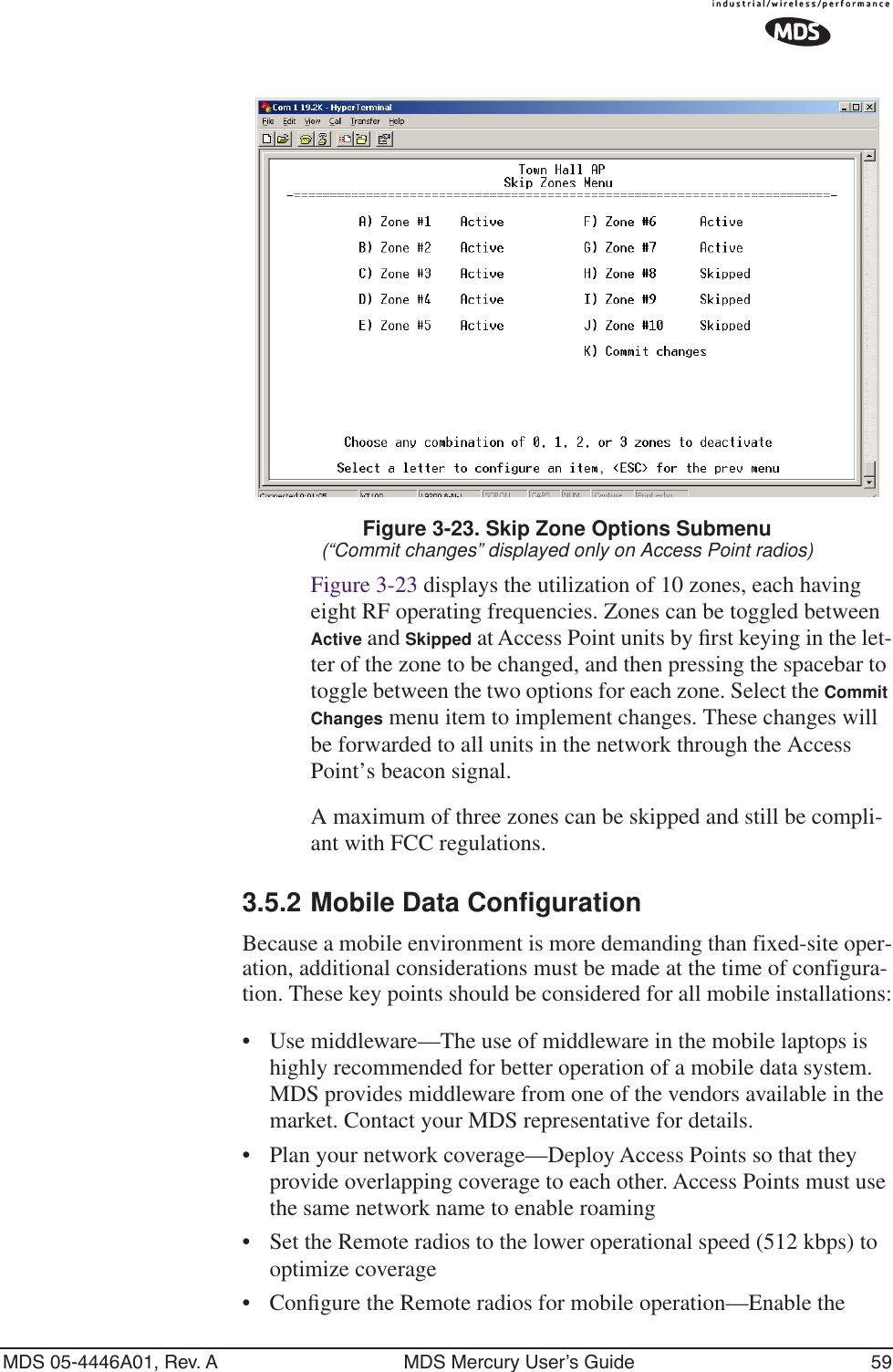
![58 MDS Mercury User’s Guide MDS 05-4446A01, Rev. AFigure 3-22 shows the default values for RSSI and SNR parameters but these may be changed to optimize performance in your environment. In properly designed systems, experience has shown that RSSI levels between -50 dBm and -90 dBm provide reliable operation, provided the signal-to-noise ratio is 17 dB or above. Tailoring the thresholds with these baseline values in mind, can provide improved performance in your system.The selections on the Auto Data Rate menu are as follows:•ADR RSSI Threshold—A specified received signal strength value, which, if exceeded by the range of the RSSI Delta set-ting, causes a data rate change in the transceiver. [-50 to -100; -87 dBm]•ADR RSSI Delta—A user-specified difference from the RSSI Threshold figure which, if exceeded, causes a data rate change in the transceiver. [0-10; 5]•ADR SNR Threshold—A user-specified signal-to-noise ratio, which, if exceeded by the range of the SNR Delta setting, causes a data rate change in the transceiver. [10-30; 26]•ADR SNR Delta—A user-specified difference from the SNR Threshold figure which, if exceeded, causes a data rate change in the transceiver. [0-10; 2]Radio Configuration Menu descriptions, continued...•Skip Zones (Does not apply to all models. Editable at AP Only.)—This selection brings up a submenu (Figure 3-23) that displays the current utilization of zones. Each zone consists of eight RF channels. In some instances there may be a part of the spectrum used by another system, that results in “continuous” or “persis-tent” interference to your system. To alleviate this form of inter-ference, the transceiver may be programmed to “block out” affected portions of the spectrum using the Skip Zones Menu.](https://usermanual.wiki/GE-MDS/DS-MERCURY900.manual-pt-1/User-Guide-703663-Page-66.png)
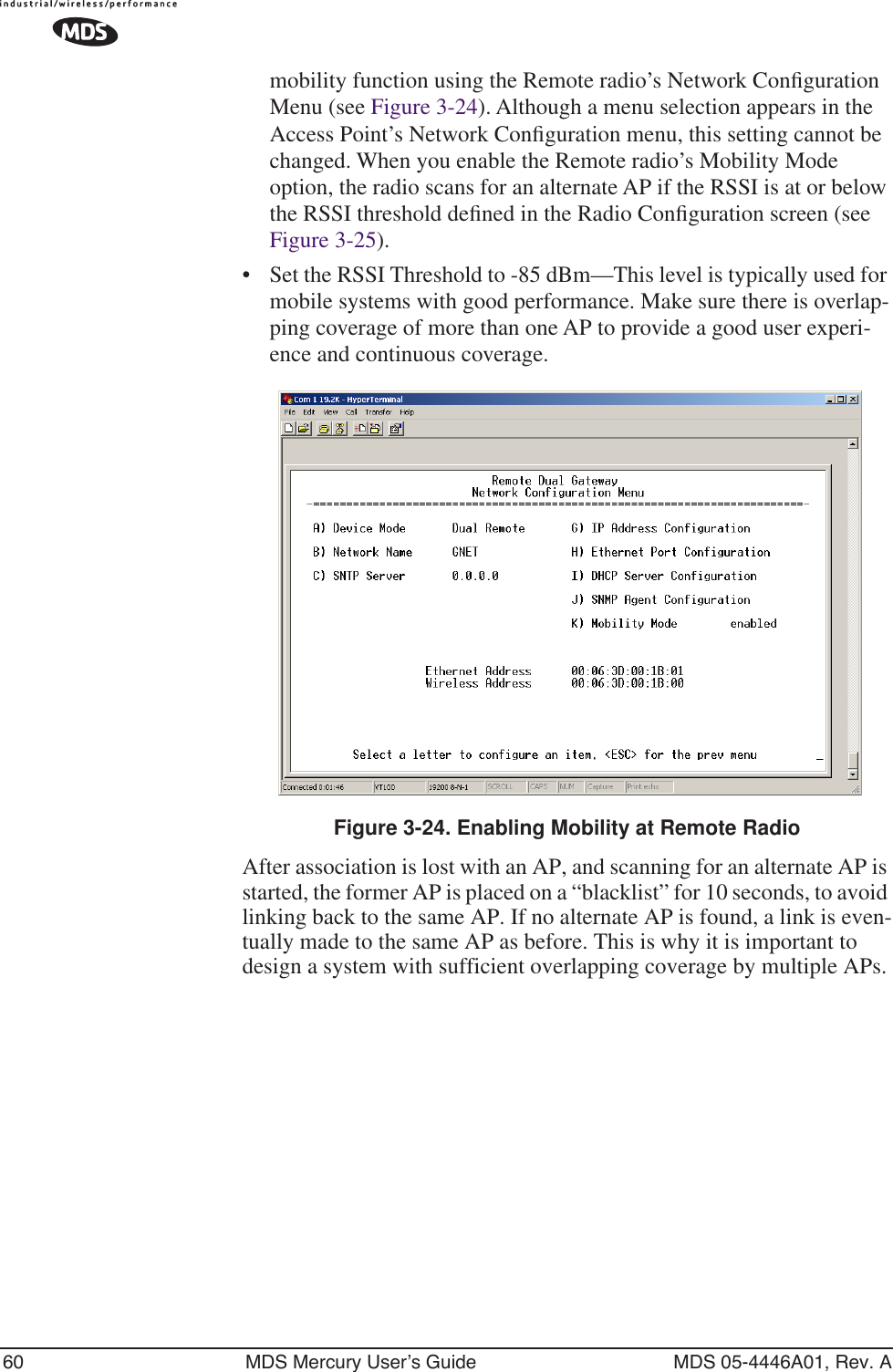
![MDS 05-4446A01, Rev. A MDS Mercury User’s Guide 61Invisible place holderFigure 3-25. Radio Configuration Menu—RemoteOther parameter settings that should be reviewed for Mobility Mode:•Compression [AP; disabled]—Disable radio compression. Data compression is best performed by the middleware running on the mobile laptop PC. Gains in efficiency are made because middleware compresses data at a higher stack level, and it aggregates multiple data frames and streams into a single packet. Compression at the radio level, although highly effi-cient, works at the individual packet level.•Dwell Time [Set to the minimum value]—This setting controls the amount of time that the unit spends on each frequency between hops. Although overall throughput appears to decrease by this setting the effects of multipath fading are minimized through frequency diversity.•Beacon Period [Set to the fastest value]—This parameter defines the interval at which the Access Point transmits a synchroniza-tion beacon to all remotes. A faster setting minimizes resyn-chronization times when remote radios roam between access points or in highly interrupted coverage areas (dense buildings, for example).•Fragmentation Threshold [remote; 256]—Set to a small value. This parameter defines the size of the message packets transmitted over the wireless media. These fragments are reconstructed into the original packet before delivery to the external device at the remote end of the link. In a mobile environment with rapidly changing conditions, setting this value to a minimum value improves the probability of packets being sent complete on the first try.](https://usermanual.wiki/GE-MDS/DS-MERCURY900.manual-pt-1/User-Guide-703663-Page-69.png)
![62 MDS Mercury User’s Guide MDS 05-4446A01, Rev. A•RTS Threshold [AP; 0 -1600 bytes]—Enable RTS flow at a small value. This setting is a wireless equivalent to RTS/CTS flow control in a wired communications circuit. This mechanism pre-vents packet collisions caused by the “Hidden Node” scenario, in which remotes can’t hear each other before transmitting. When this value is set below 100 or above 1500, it is effectively disabled.3.6 CONFIGURING THE SERIAL INTERFACES3.6.1 OverviewThe transceiver includes an embedded serial device server that provides transparent encapsulation over IP. In this capacity, it acts as a gateway between serial and IP remote devices. Two common scenarios are PC applications using IP to talk to remote devices, and serial PC applica-tions talking to remote serial devices over an IP network.Note that the transceiver’s COM1 port is DCE. Therefore, if the equip-ment to be connected is also DCE, then a null-modem cable will need to be used.Com1 Port–Dual Purpose CapabilityThe COM1 port is used as a local console connection point and to pass serial data with an external device. Setting the COM1 port status to Enable prevents access to the Management System (MS) through this port. However, the MS can still be accessed via the LAN port using Telnet or a web browser.To restore the COM1 port to support Management System services, connect a terminal to the port, select the proper baud rate (19,200 is default), and enter an escape sequence (+++) to reset it to the console mode.TCP vs. UDPBoth types of IP services are used by the transceiver embedded serial device server—TCP and UDP. TCP provides a connection-oriented link with end-to-end acknowledgment of data, but with some added over-head. UDP provides a connectionless best-effort delivery service with no acknowledgment.Most polled protocols will be best served by UDP service as the protocol itself has built-in error recovery mechanisms. UDP provides the needed multidrop operation by means of multicast addressing.On the other hand, TCP services are best suited for applications that do not have a recovery mechanism (error-correction) and must have the](https://usermanual.wiki/GE-MDS/DS-MERCURY900.manual-pt-1/User-Guide-703663-Page-70.png)
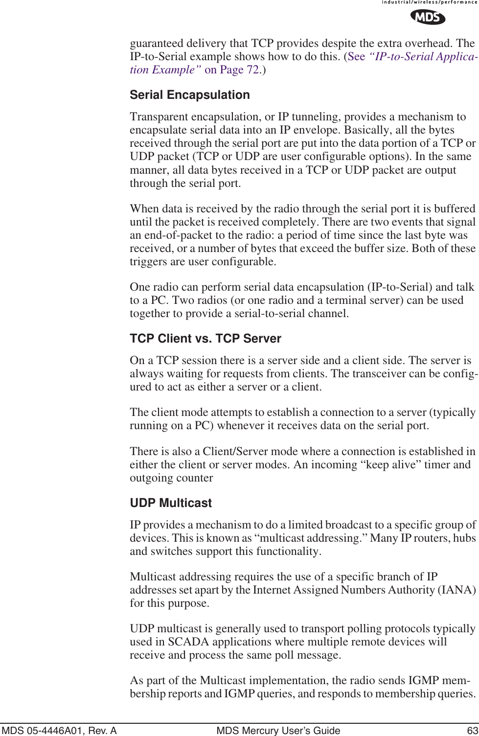
![66 MDS Mercury User’s Guide MDS 05-4446A01, Rev. AUDP point-to-multipoint to send a copy of the same packet to multiple destinations, such as in a polling protocol.•Status—Enable/Disable the serial data port. •IP Protocol—Point to Multipoint [TCP, UDP PPP; TCP]. This is the type of IP port that will be offered by the transceiver’s serial device server.•Multicast IP Address (used instead of Local IP Address when using UDP Point-to-Multipoint.)— Must be configured with a valid Class D IP address (224.0.0.0–239.255.255.255). IP packets received with a matching destination address will be processed by this unit [Any legal IP address; 0.0.0.0].•Multicast IP Port (used instead of Local IP Port when using UDP Point-to-Multipoint.)—This port number must match the number used by the application connecting to local TCP or UDP socket. [1-64,000; 30010]•Local IP Port—Receive IP data from this source and pass it through to the connected serial device. The port number must be used by the application connecting to local TCP or UDP socket. [Any valid IP port; 30010]•Time to Live (TTL)—An IP parameter defining the number of hops that the packet is allowed to traverse. Every router in the path will decrement this counter by one.•Packet Redundancy Mode— For proper operation, all radios’ Serial Packet Redundancy mode must match (Single Packet mode vs. Packet Repeat mode). This is because a transceiver, when in Packet Repeat mode, sends 12 extra characters (sequence numbers, etc.) to control the delivery of the repeated data. Misconfigurations can result in undesired operation.•Data Baud Rate—Data rate (payload) for the COM port in bits-per-second. [1,200–115,200; 19200] •Configuration—Formatting of data bytes. Data bits, parity and stop bits [7N1, 7E1, 7O1, 8N1, 8E1, 8O1, 8N1, 7N2, 7E2, 7O2, 8N2, 8E2, 8O2; 8N1].•Flow Control [Com1 port]—RTS/CTS handshaking between the transceiver and the connected device. [Enable, Disable; Dis-abled]•Serial Mode—When seamless mode is selected data bytes will be sent over the air as quickly as possible, but the receiver will buffer the data until enough bytes have arrived to cover worst-case gaps in transmission. The delay introduced by data buffering may range from 22 to 44 ms, but the radio will not create any gaps in the output data stream. This permits operation with protocols such as MODBUS™ that do not allow gaps in their data transmission. [Seamless, Custom; Seamless]](https://usermanual.wiki/GE-MDS/DS-MERCURY900.manual-pt-1/User-Guide-703663-Page-74.png)
![MDS 05-4446A01, Rev. A MDS Mercury User’s Guide 67•Seamless Inter-Frame Delay— Number of characters that repre-sent the end of a message (inter-character time-out). UDP packet sizes are delimited and sent out based on the Seamless Inter-Frame Delay only when receiving data through the serial port. MODBUS defines a “3.5-character” parameter. [1–65,535; 4]•Custom Data Buffer Size (Custom Packet Mode only)—Maxi-mum amount of characters, that the Remote end will buffer locally before starting to transmit data through the serial port. [16, 32, 64, 128, 256; 32]•Commit Changes and Exit Wizard—Save and execute changes made on this screen (Shown only after changes have been entered.) Invisible place holderFigure 3-28. UDP Point-to-Point MenuUse UDP point-to-point configuration to send information to a single device.•Status—Enable/Disable the serial data port. •IP Protocol—UDP Point-to-Point. This is the type of IP port that will be offered by the transceiver’s serial device server. [TCP, UDP, PPP; TCP]•Remote IP Address—Data received through the serial port is sent to this IP address. To reach multiple Remotes in the net-work, use UDP Point-to-Multipoint. [Any legal IP address; 0.0.0.0]•Remote IP Port—The destination IP port for data packets received through the serial port on the transceiver. [1–64,000; 30010]•Local IP Port—Port number where data is received and passed through to the serial port. This port number must be used by the application connecting to this transceiver. [1–64,000; 30010]](https://usermanual.wiki/GE-MDS/DS-MERCURY900.manual-pt-1/User-Guide-703663-Page-75.png)
![68 MDS Mercury User’s Guide MDS 05-4446A01, Rev. A•Packet Redundancy Mode— For proper operation, all radios’ Serial Packet Redundancy mode must match (Single Packet mode vs. Packet Repeat mode). This is because a transceiver, when in Packet Repeat mode, sends 12 extra characters (sequence numbers, etc.) to control the delivery of the repeated data. Misconfigurations can result in undesired operation.•Data Baud Rate—Data rate (payload) for the COM port in bits-per-second. [1,200–115,200; 19200] •Configuration—Formatting of data bytes. Data bits, parity and stop bits [7N1, 7E1, 7O1, 8N1, 8E1, 8O1, 8N1, 7N2, 7E2, 7O2, 8N2, 8E2, 8O2; 8N1].•Flow Control (COM1 port)—RTS/CTS handshaking between the transceiver and the connected device.[Enable, Disable; Disabled]•Serial Mode— When seamless mode is selected, data bytes will be sent over the air as quickly as possible, but the receiver will buffer the data until enough bytes have arrived to cover worst case gaps in transmission. The delay intro-duced by data buffering may range from 22 to 44 ms, but the radio will not create any gaps in the output data stream. This mode of operation is required for protocols such as MOD-BUS™ that do not allow gaps in their data transmission. [Seamless, Custom; Seamless]•Seamless Inter-Frame Delay— Number of characters that repre-sent the end of a message (inter-character time-out). MOD-BUS defines a “3.5-character” parameter. [1–65,535; 4]•Custom Data Buffer Size (Custom Packet Mode only)—Maxi-mum amount of characters, that the Remote end will buffer locally before starting to transmit data through the serial port. [16, 32, 64, 128, 256; 32]•Commit Changes and Exit Wizard—Save and execute changes made on this screen (Shown only after changes have been entered.)](https://usermanual.wiki/GE-MDS/DS-MERCURY900.manual-pt-1/User-Guide-703663-Page-76.png)
![MDS 05-4446A01, Rev. A MDS Mercury User’s Guide 693.6.4 Configuring for TCP ModeInvisible place holderFigure 3-29. TCP Client Menu (Remote)•Status—Enable/Disable the serial data port. •IP Protocol—TCP Client. This is the type of IP port that will be offered by the transceiver’s serial device server. [TCP, UDP, PPP; TCP]•Primary Host Address—The IP address to be used as a destina-tion for data received through the serial port.[Any legal IP address; 0.0.0.0]•Primary IP Port—The destination IP port for data packets received through the serial port on the transceiver.[Any valid IP port; 30010]•Secondary Host Address—The IP address to be used as a desti-nation for data received through the serial port in case the pri-mary host address is not available.[Any legal IP address; 0.0.0.0]•Secondary IP Port—The destination IP port for data packets received through the serial port on the transceiver used along with the secondary host address above.[Any valid IP port; 30010]•Outgoing Connection’s Inactivity Timeout—Amount of time (in seconds) that they transceiver will wait for data before termi-nating the TCP session. [0–600; 600]•Data Baud Rate—Data rate (payload) for the COM port in bits-per-second. [1,200–115,200; 19200] •Configuration—Interface signaling parameters. Data bits, par-ity and stop bits [7N1, 7E1, 7O1, 8N1, 8E1, 8O1, 8N1, 7N2, 7E2, 7O2, 8N2, 8E2, 8O2; 8N1].•Flow Control [Com1 port]—RTS/CTS handshaking between the transceiver and the connected device.[Enable, Disable; Disabled]](https://usermanual.wiki/GE-MDS/DS-MERCURY900.manual-pt-1/User-Guide-703663-Page-77.png)
![70 MDS Mercury User’s Guide MDS 05-4446A01, Rev. A•Serial Mode— If data buffering is Enabled, the radio will oper-ate in seamless mode. Data bytes will be sent over the air as quickly as possible, but the receiver will buffer the data until enough bytes have arrived to cover worst case gaps in trans-mission. The delay introduced by data buffering may range from 22 to 44 ms, but the radio will not create any gaps in the output data stream. This mode of operation is required for protocols such as MODBUS™ and some variants which do not allow gaps in their data transmission.[Seamless, Custom; Seamless]•Seamless Inter-Frame Delay— Number of characters that repre-sent the end of a message (inter-character time-out). MOD-BUS defines a “3.5-character” parameter.[1–65,535; 4]•Custom Data Buffer Size (Custom Packet Mode only)—Maxi-mum amount of characters, that the Remote end will buffer locally before starting to transmit data through the serial port. [16, 32, 64, 128, 256; 32]•Commit Changes and Exit Wizard—Save and execute changes made on this screen (Shown only after changes have been entered.) Invisible place holderFigure 3-30. TCP Server Menu (AP)•Status—Enable/Disable the serial data port. •IP Protocol—TCP Server. This is the type of IP port that will be offered by the transceiver’s serial device server. [TCP, UDP, PPP; TCP]•Local Listening IP Port—Receive IP data from this source and pass it through to the connected serial device. The port num-ber must be used by the application connecting to local TCP or UDP socket.[Any valid IP port; 30010]](https://usermanual.wiki/GE-MDS/DS-MERCURY900.manual-pt-1/User-Guide-703663-Page-78.png)
![MDS 05-4446A01, Rev. A MDS Mercury User’s Guide 71•Data Baud Rate—Data rate (payload) for the COM port in bits-per-second. [1,200–115,200; 19200] •Configuration—Interface signaling parameters. Data bits, par-ity and stop bits [7N1, 7E1, 7O1, 8N1, 8E1, 8O1, 8N1, 7N2, 7E2, 7O2, 8N2, 8E2, 8O2; 8N1].•Flow Control (COM1 port)—RTS/CTS handshaking between the transceiver and the connected device.[Enable, Disable; Disabled]•Serial Mode— If data buffering is Enabled, the radio will oper-ate in seamless mode. Data bytes will be sent over the air as quickly as possible, but the receiver will buffer the data until enough bytes have arrived to cover worst case gaps in trans-mission. The delay introduced by data buffering may range from 22 to 44 ms, but the radio will not create any gaps in the output data stream. This mode of operation is required for protocols such as MODBUS™ and some variants which do not allow gaps in their data transmission. [Seamless, Custom; Seamless]•Seamless Inter-Frame Delay— Number of characters that repre-sent the end of a message (inter-character time-out). MOD-BUS defines a “3.5-character” parameter. [1–65,535; 4]•Custom Data Buffer Size (Custom Packet Mode only)—Maxi-mum amount of characters, that the Remote end will buffer locally before starting to transmit data through the serial port. [16, 32, 64, 128, 256; 32]•Commit Changes and Exit Wizard—Save and execute changes made on this screen (Shown only after changes have been entered.)3.6.5 Configuring for PPP ModeInvisible place holderFigure 3-31. PPP Menu](https://usermanual.wiki/GE-MDS/DS-MERCURY900.manual-pt-1/User-Guide-703663-Page-79.png)
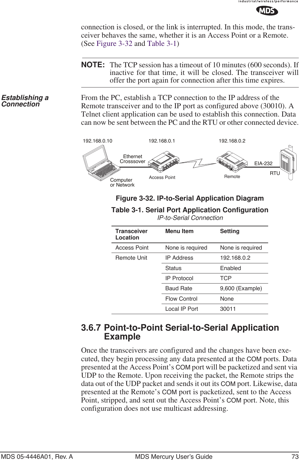
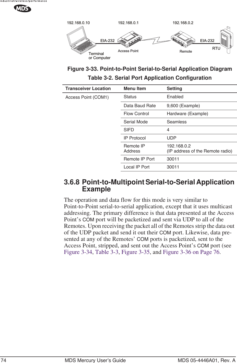
![72 MDS Mercury User’s Guide MDS 05-4446A01, Rev. A•Status—Enable/Disable the serial data port. •IP Protocol—PPP. This is the type of IP port that will be offered by the transceiver’s serial device server. [TCP, UDP, PPP; TCP]•Device IP Address—IP address that will be assigned to the dialing device once the connection is established. [0.0.0.0]•Data Baud—The baud rate of the serial port of the transceiver to which the external device is connected.[1200, 2400, 4800, 9600, 19200, 38400, 57600, 115200; 19200]•Configuration—Byte format of the serial port [7N1, 7E1, 701, 7N2, 7E2, 702, 8N1, 801, 8N2, 8E2, 802; 8N1]•Flow Control (COM1 port)—RTS/CTS handshaking between the transceiver and the connected device. [Enable, Disable; Disabled]•Serial Mode—When seamless mode is selected, data bytes will be sent over the air as quickly as possible, but the receiver will buffer the data until enough bytes have arrived to cover worst case gaps in transmission. The delay introduced by data buffer-ing may range from 22 to 44 ms, but the radio will not create any gaps in the output data stream. This mode of operation is required for protocols such as MODBUS™ that do not allow gaps in their data transmission. [Seamless, Custom; Seamless]•Seamless Inter-Frame Delay— Number of characters that represent the end of a message (inter-character time-out). MODBUS defines a “3.5-character” parameter. [1–65,535; 4]•Custom Data Buffer Size (Custom Packet Mode only)—Maxi-mum amount of characters, that the Remote end will buffer locally before starting to transmit data through the serial port. [16, 32, 64, 128, 256; 32]•Commit Changes and Exit Wizard—Save and execute changes made on this screen (Shown only after changes have been entered.)A PPP session shows the following possible states:•Sending LCP Requests—The PPP server is querying for any cli-ents that need to connect.•Link Established—A successful PPP connection has been negoti-ated and an IP address is assigned.•Port not Enabled—The serial port is disabled.3.6.6 IP-to-Serial Application ExampleYou have a choice to use UDP or TCP to establish communications. This will depend on the type of device you are communicating with at the other end of the IP network. In this example we will use TCP to illus-trate its use. In TCP mode, the transceiver remains in a passive mode offering a socket for connection. Once a request is received, data received at the serial port will be sent out through the IP socket and vice versa, until the](https://usermanual.wiki/GE-MDS/DS-MERCURY900.manual-pt-1/User-Guide-703663-Page-80.png)
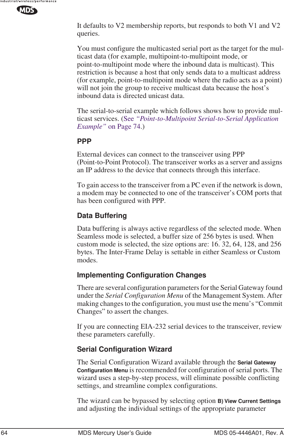
![MDS 05-4446A01, Rev. A MDS Mercury User’s Guide 79Invisible place holderFigure 3-38. Device Security Menu•User Auth Method— Defines whether username and password is verified locally or via a central server. [Local, RADIUS; Local]•User Auth Fallback— Defines the alternate authentication mode in case the authentication server is not available.[Local, None; Local]•User Password—Local password for this unit. Used at log-in via COM1 Port, Telnet, SSH and Web browser. [Up to 8 alphanumeric characters without spaces (case-sensitive); admin]TIP: For enhanced security, consider using misspelled words, a combi-nation of letters and numbers, and a combination of upper and lower case letters. Also, the more characters used (up to eight), the more secure the password will be. These strategies help protect against sophisticated hackers who may use a database of common words (for example, dictionary attacks) to determine a password.•SNMP Mode—This specifies the mode of operation of the radio’s SNMP Agent. If the mode is disabled, the Agent does not respond to any SNMP traffic. If the mode is v1_only, v2_only, or v3_only, the Agent responds only to that version of SNMP traffic. If the mode is v1-v2, or v1-v2-v3, the Agent responds to the specified version of SNMP traffic.[disabled, v1_only, v2_only, v3_only, v1-v2, v1-v2-v3; v1-v2-v3]•Telnet Access—Controls remote access through Telnet sessions on Port 23 [Enabled, Disabled; Enabled]•SSH Access— Controls remote access through SSH (Secure Shell) sessions on Port 22 [Enabled, Disabled; Enabled]•HTTP Mode— Controls remote access through HTTP sessions on Ports 80 and 443. Selecting HTTPS forces secure connections to Port 443. When HTTP Mode is disabled, access through HTTP or HTTPS is not allowed. [Disabled, HTTP, HTTPS; HTTP]](https://usermanual.wiki/GE-MDS/DS-MERCURY900.manual-pt-1/User-Guide-703663-Page-87.png)
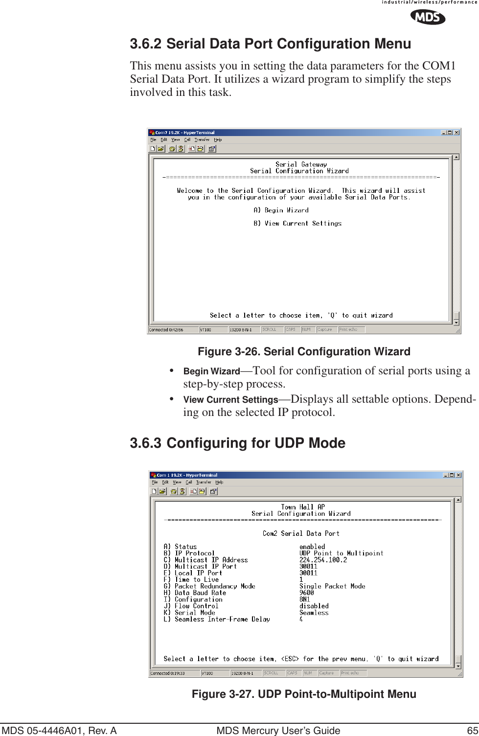
![80 MDS Mercury User’s Guide MDS 05-4446A01, Rev. A•HTTP Auth Mode—Selects the method of HTTP log-in authenti-cation. This parameter functions only when HTTP is selected in the previous menu item. Although the Basic Auth mode requests a password, the actual password text is transmitted in the clear (unencrypted). [Basic Auth, MD5 Digest; Basic Auth]3.7.2 Wireless SecurityThe features in the Wireless Security menu control the communication of data across the wireless link. The radios can be authenticated locally via a list of authorized radios, or remotely via a centralized RADIUS server. RADIUS is a centralized authentication mechanism based on standards.Invisible place holderFigure 3-39. Wireless Security Menu•Device Auth Method—Controls whether device authentication is executed locally, via a central server, or not at all. Selecting Local uses the Approved Remotes List described later in this manual. [None, Local, RADIUS; None]•Encryption— When enabled, it forces the transceiver to use AES-128 encryption (RC4-128) on all over-the-air messages. This option requires the Encryption Phrase to be previously configured. Both the AP and the Remote radios must use the same encryption phrase. (Some units may not be authorized to use encryption. “See “Authorization Keys Menu” on Page 114” for additional details.) [Enabled, Disabled; Disabled]•Auto Key Rotation—When enabled, it forces the transceiver to use the key rotation algorithm to generate a new encryption key after 500 kilobytes of information has been transmitted, or one hour has elapsed. [Enabled, Disabled; Disabled]•Approved Access Points/Remotes List —Displays a menu to man-age the list of other radios with which this unit will be permitted to communicate.](https://usermanual.wiki/GE-MDS/DS-MERCURY900.manual-pt-1/User-Guide-703663-Page-88.png)
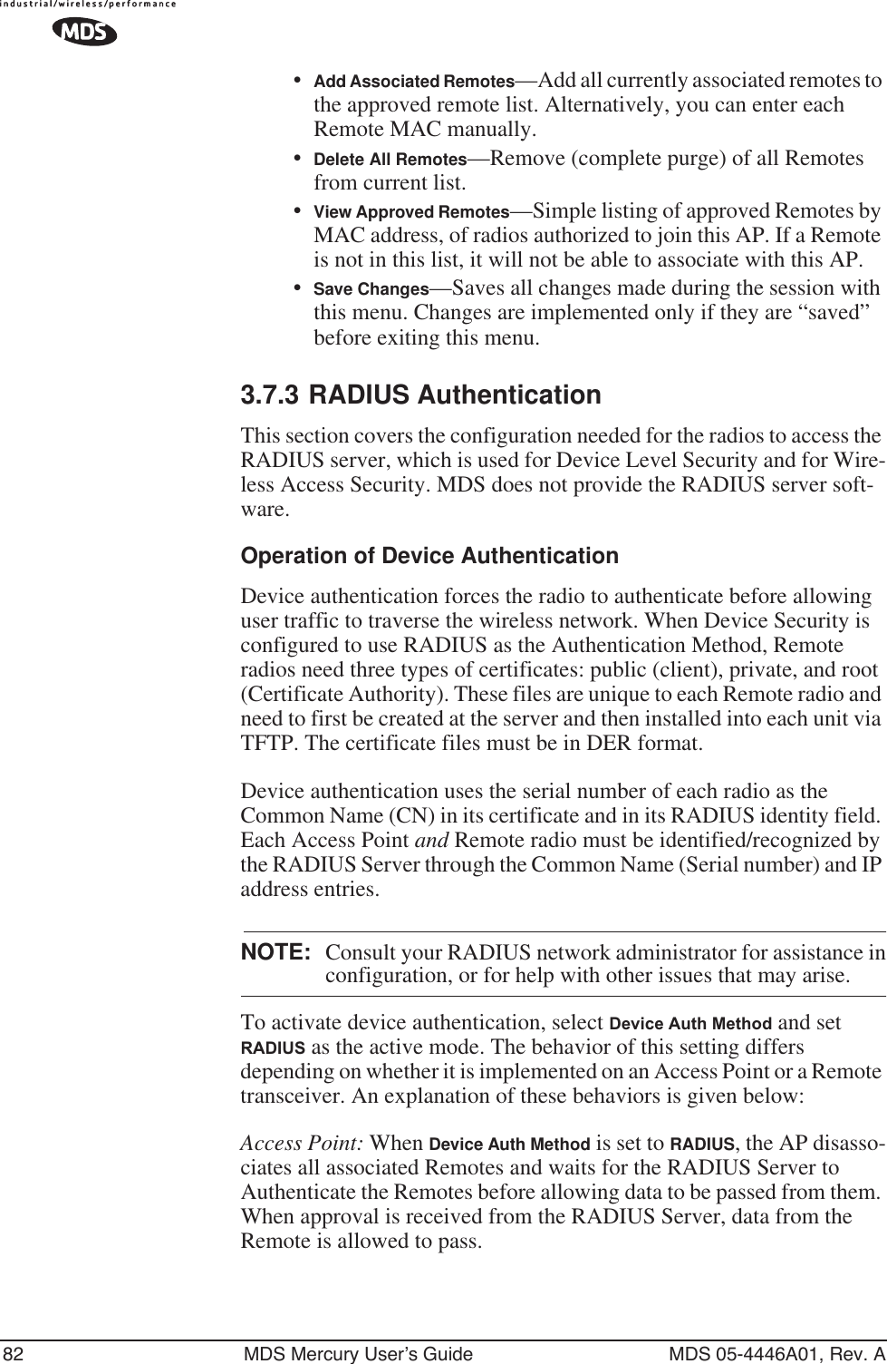
![MDS 05-4446A01, Rev. A MDS Mercury User’s Guide 81•Encryption Phrase—Phrase (text & numbers) that will be used by the encryption algorithm.[8 to 29 alphanumeric characters; Blank]•Force Key Rotation— It triggers an immediate key rotation of the encryption keys before the internal counters do it automatically.Local Authentication—Approved Remotes/Access Points List SubmenuSetting the Device Auth Method to Local forces the transceiver to check the Approved AP List before a radio link can be established. In the case of a Remote, the AP must be in the Approved Access Points List before it accepts the beacon as being valid. In the case of an AP, a Remote must be in the Approved Remotes List to be granted authorization. Before enabling this option, at least one entry must already exist in the Approved AP/Remotes List.This menu is the same for both Access Points and Remotes and the names change to reflect their mode. Replace “Remotes” with Access Points” in the following description.NOTE: The limit for Remotes (in an Access Point radio) is 255. Thelimit for Access Points (in a Remote radio) is 104. Figure 3-40. Approved Remotes List Menu•Add Remote—Enter MAC address of Remote.[Any valid 6-digit hexadecimal MAC address; 00:00:00:00:00:00] •Delete Remote—Enter MAC address of Remote. For security purposes, you may want to delete a stolen or deprovisioned radio from this list.](https://usermanual.wiki/GE-MDS/DS-MERCURY900.manual-pt-1/User-Guide-703663-Page-89.png)
![84 MDS Mercury User’s Guide MDS 05-4446A01, Rev. ANOTE: The security password may not exceed 40 characters in length.3.7.5 Certificate Management (Remote transceivers only)Use Certificate generation software to generate certificate files and then install these files into each Remote unit via TFTP. The certificate files must be in DER format. The Common Name (CN) field in the public certificate file must match the serial number of the unit it will be installed in.Invisible place holderFigure 3-42. Manage Certificates Menu(NOTE: The appearance of this screen differs from the others because a different terminal program was used; Menu content is the same regardless of program.)•Server IP Address—the IP address of the Server where the RADIUS application resides.•TFTP Timeout should be set appropriately according to the layout of the network.Three certificate files (Root, Client, and Private Key) must be present in each of the Remote radios. Use the commands described below to install these files into each Remote radio.•Certificate Filename—Used to specify the filename of the certifi-cate file residing on the TFTP server.•Certificate Type—Selects one of the three file types mentioned above. [Root Certificate, Client Certificate, Private Key Certificate; Root Certificate]•Retrieve Certificate—Initiates the retrieval of the certificate file from the storage location. A successful installation issues a Com-plete status message.](https://usermanual.wiki/GE-MDS/DS-MERCURY900.manual-pt-1/User-Guide-703663-Page-92.png)