GE MDS DS-MERCURY900 Mercury 900 Wireless Transceiver User Manual Book1
GE MDS LLC Mercury 900 Wireless Transceiver Book1
UserManual.wiki
>
GE MDS
>
DS-MERCURY900 User Manual
>
manual pt 2
Contents
1.
manual pt 1
2.
manual pt 2
3.
User Manual 1
4.
User Manual 2
5.
Users Manual Revised 121908 Part 1
6.
Users Manual Revised 121908 Part 2
7.
Users Manual Revised 121908 Part 3
manual pt 2
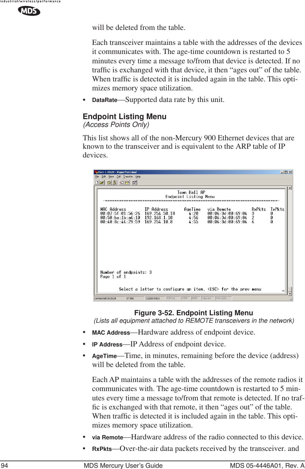
Navigation menu
Upload a User Manual
Namespaces
Wiki Guide
HTML
PDF
Info
Views
User Manual
Discussion / Help
Navigation
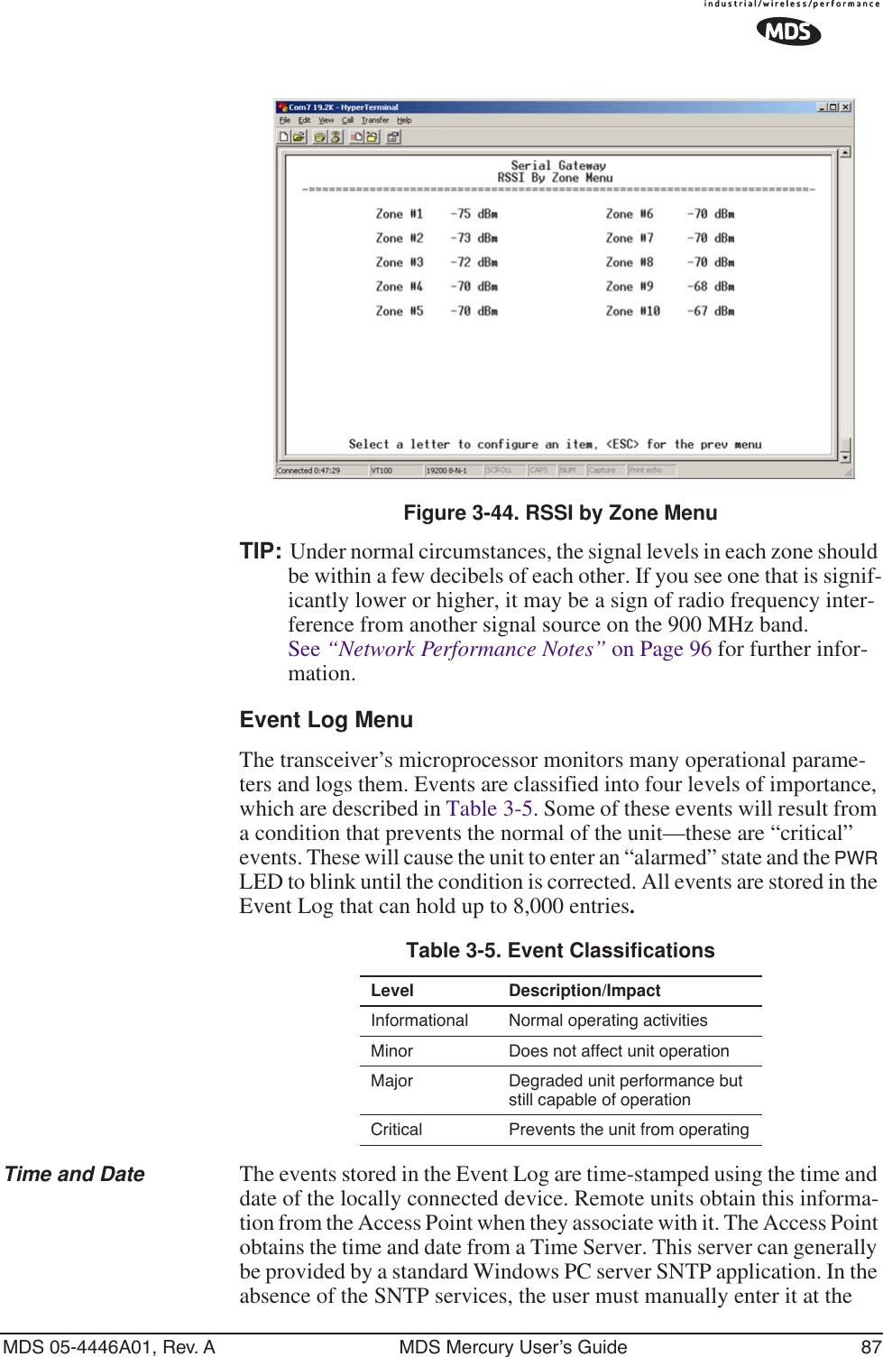
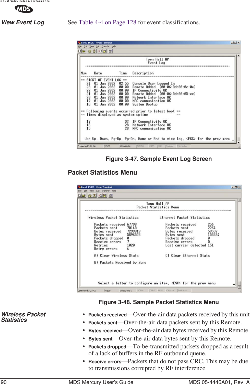
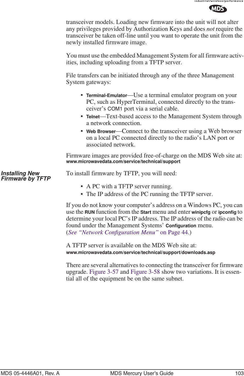
![88 MDS Mercury User’s Guide MDS 05-4446A01, Rev. AAccess Point. (See “Device Information” on Page 42 for SNTP server identification.) The manually set time and date clock is dependent on the unit’s primary power. A loss of power will reset the clock to January 1, 2002 but will not affect previously stored error events.Figure 3-45. Event Log Menu •Current Alarms (Telnet/Terminal only)—View list of root causes that have placed the Device Status in the alarmed state. (See “Alarm Conditions” on Page 128)•View Log—View a list of events stored in the current log. Some of these events are stored in volatile memory and will be erased with a loss of power. The events are numbered for easier iden-tification and navigation.•Clear Log—Purges the log of all eventsTIP: Save your Event Log before choosing to clear it in order to retain potentially valuable troubleshooting information. (See “Upgrading the Firmware” on Page 102 for an over-view on how to transfer files from the transceiver to a com-puter on the network using TFTP.)•Send Log (Telnet/Terminal only)—Initiate TFTP transfer of the unit’s event Event Log in a plain text (ASCII) file to a TFTP server at the remote location.•TFTP Host Address (Telnet/Terminal only)—IP address of the com-puter on which the TFTP server resides. This same IP address is used in other screens/functions (reprogramming, logging, etc.). Changing it here also changes it for other screens/functions.[Any valid IP address; 127.0.0.1]](https://usermanual.wiki/GE-MDS/DS-MERCURY900.manual-pt-2/User-Guide-703664-Page-2.png)
![MDS 05-4446A01, Rev. A MDS Mercury User’s Guide 89•Filename (Telnet/Terminal only)—Name to be given to the Event Log file sent to the TFTP server for archiving. [Any 40-char alphanumeric string; Blank]NOTE: You may want to change the filename to reflect the type of log you intend to archive and/or its date. •TFTP Time-out (Telnet/Terminal only)—Time in seconds the TFTP server will wait for a packet ACK (acknowledgment) from the transceiver before suspending the file transfer.[10 to 120 seconds; 10]•Syslog Server—IP address to which alarms are sent using the sys-log message format. [Any valid IP address; 0.0.0.0]View Current Alarms Most events, classified as “critical” will make the PWR LED blink, and will inhibit normal operation of the transceiver. The LED will remain blinking until the corrective action has been completed.An alarm condition is different from a log event in the sense that an alarm is persistent in nature. That is, an alarm condition remains as an alarm until it has been cleared by correcting the cause (see Table 4-6 on Page 130 for corrective action).Figure 3-46. Current Alarms Screen](https://usermanual.wiki/GE-MDS/DS-MERCURY900.manual-pt-2/User-Guide-703664-Page-3.png)
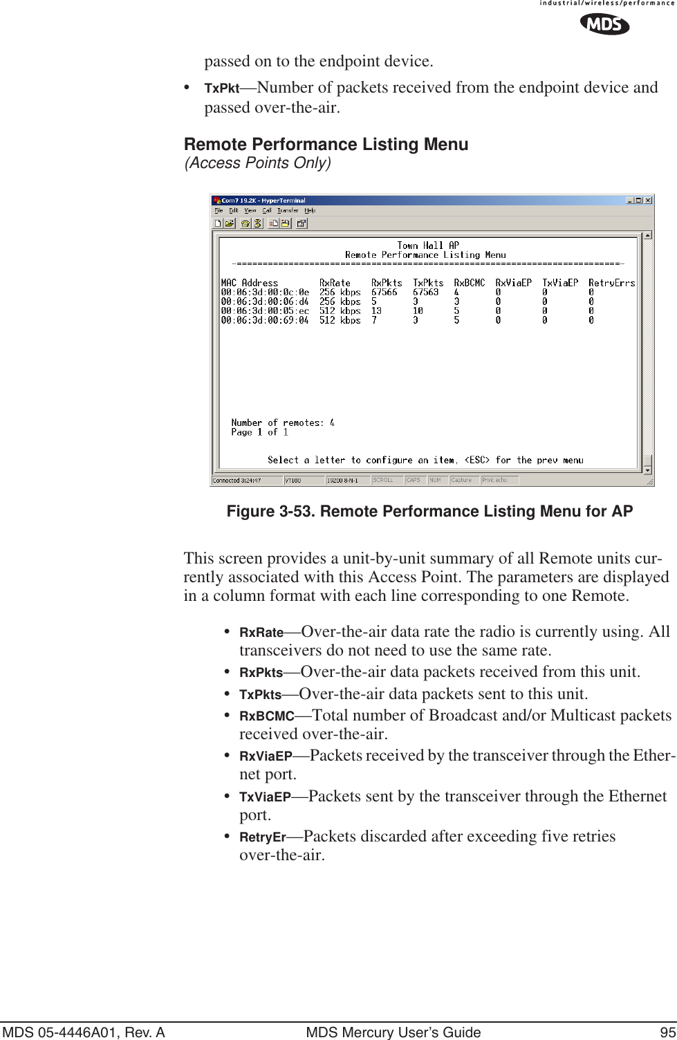
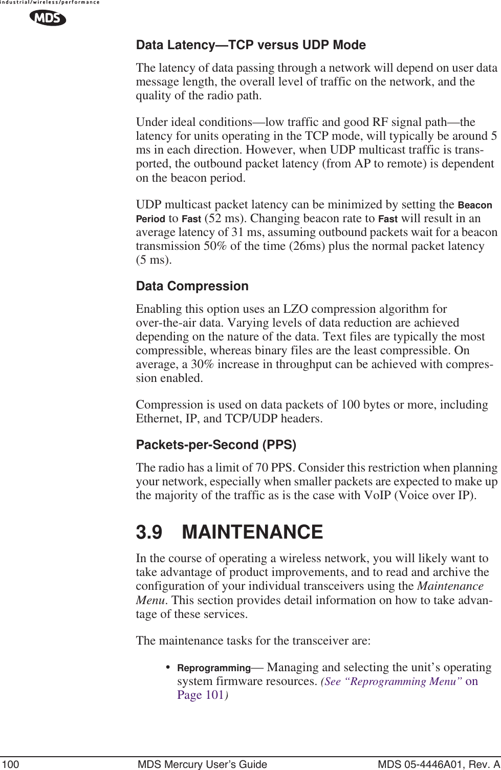
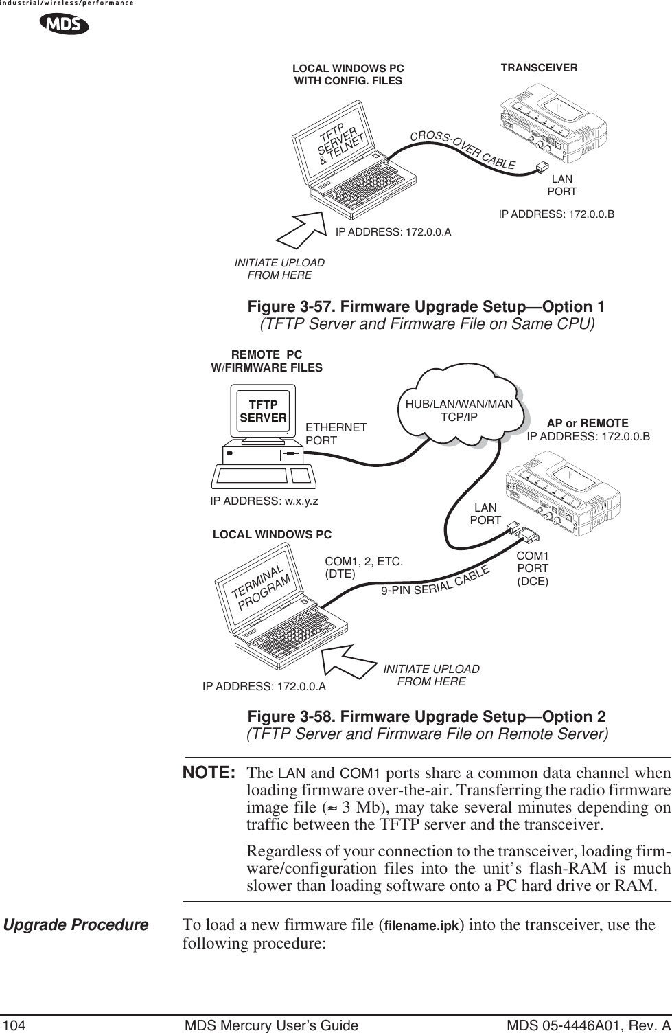
![102 MDS Mercury User’s Guide MDS 05-4446A01, Rev. AFigure 3-56. Reprogramming Menu(Shown with “Image Copy” Selected)•TFTP Host Address—IP address of the host computer from which to get the file. [Any valid IP address] This same IP address is used in other screens/functions (reprogramming, logging, etc.). Changing it here also changes it for other screens/functions.•Filename—Name of file to be received by the TFTP server.[Any 40-character alphanumeric string] Verify that this corresponds to the TFTP directory location. May require sub-directory, for example: \firmware\mercury\mercury-4_4_0.ipk.•TFTP Timeout—Time in seconds the TFTP server will wait for a packet ACK (acknowledgment) from the transceiver before suspending the file transfer. [2 to 60 seconds; 10]•Retrieve File—Initiate the file transfer from the file from TFTP server. Placed into inactive firmware position in the trans-ceiver’s non-volatile memory [Y, N]•Image Verify—Initiate the verification of the integrity of firmware file held in unit.•Image Copy—Initiate the copying of the active firmware into the inactive image.•Reboot Device—Initiate rebooting the transceiver. This will interrupt data traffic through this unit, and the network if per-formed on an Access Point. Intended to be used to toggle between firmware images.NOTE: See “Upgrading the Firmware” on Page 102 for details on setting up the TFTP server.Upgrading the FirmwareFrom time-to-time MDS offers upgrades to the transceiver firmware. One version of the firmware provides core software resources for all](https://usermanual.wiki/GE-MDS/DS-MERCURY900.manual-pt-2/User-Guide-703664-Page-16.png)
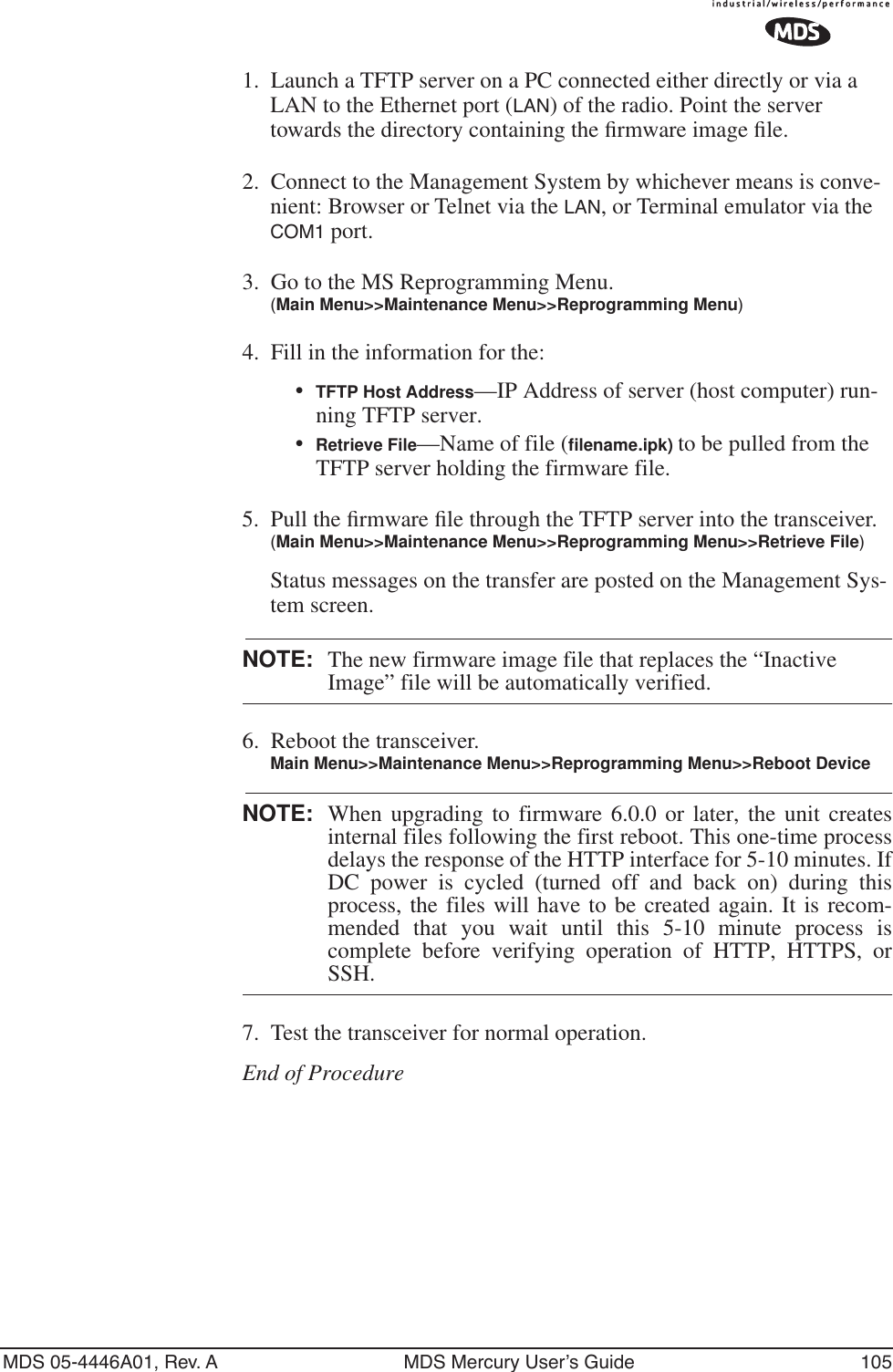
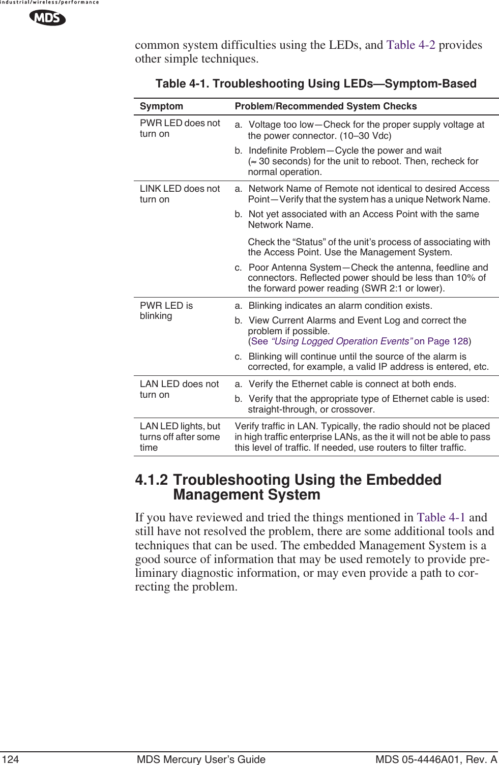
![106 MDS Mercury User’s Guide MDS 05-4446A01, Rev. AError Messages During File TransfersIt is possible to encounter errors during a file transfer. In most cases errors can be quickly corrected by referring to Table 3-6.3.9.2 Configuration Scripts MenuFigure 3-59. Configuration Files Menu•TFTP Host Address—IP address of the computer on which the TFTP server resides. [Any valid IP address]Table 3-6. Common Errors During TFTP Transfer Error Message Likely Cause/Corrective ActionInvalid File Type Indicates that the file is not a valid firmware file. Locate proper file and re-load.File not found Invalid or non-existent filename on TFTP serverInvalid file path Invalid or non-existent file path to TFTP serverTimeout TFTP transfer time expired. Increase the timeout value.Flash Error Flash memory error. Contact factory for assistance.Bad CRC Cyclic Redundancy Check reporting a corrupted file. Attempt to re-load, or use a different file.Version String Mismatch Invalid file detected. Attempt to re-load, or use a different file.Sending LCP Requests The PPP server is querying for any clients that may need to connect.Port not Enabled The serial port is disabled.](https://usermanual.wiki/GE-MDS/DS-MERCURY900.manual-pt-2/User-Guide-703664-Page-20.png)
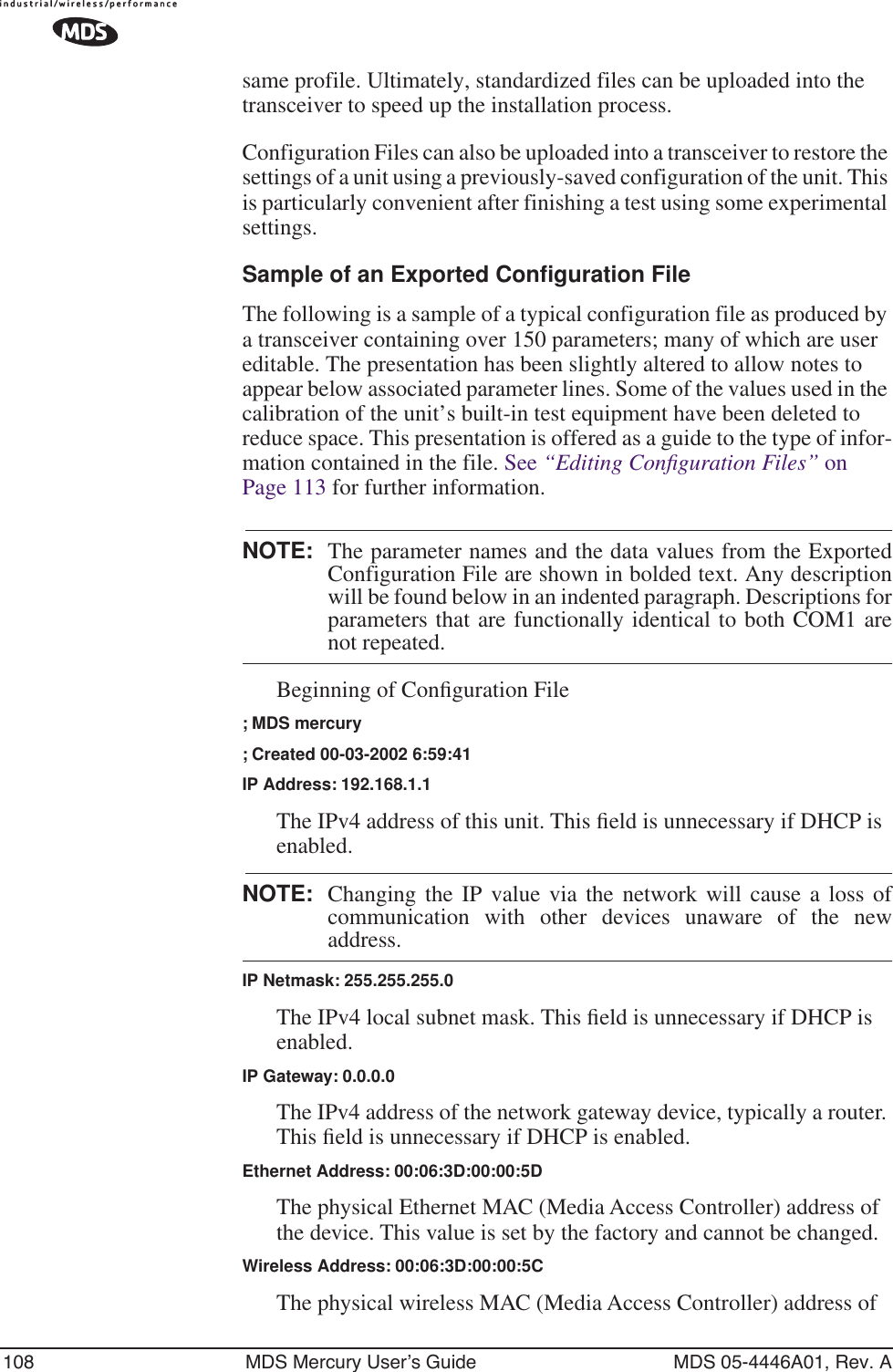
![MDS 05-4446A01, Rev. A MDS Mercury User’s Guide 107•Filename—Name of file containing this unit’s configuration pro-file that will be transferred to the TFTP server. The configura-tion information will be in a plain-text ASCII format.[Any 40-character alphanumeric string] May require sub-directory, for example: config\mercury-config.txt. (See “Using Configura-tion Scripts” on Page 107)NOTE: The filename field is used in identifying the desired incoming file and as the name of file being exported to the TFTP server. Before exporting the unit’s configuration, you may want to name it something that reflect the unit’s services or identifi-cation.•TFTP Timeout—Time in seconds the TFTP server will wait for a packet ACK (acknowledgment) from the transceiver before suspending the file transfer. [10 to 120 seconds; 10]•Retrieve File—Initiate the file transfer of the configuration file from TFTP server into the transceiver.•Send File—Initiate the file transfer from the transceiver’s current configuration file to TFTP server.NOTE: See Upgrading the Firmware on Page 102 for details onsetting up the TFTP server.A Brief Description of Configuration FilesIf you plan to have more than a few radios in your network, use the con-figuration file feature to configure similar units from a common set of parameters. There are over 50 user-controllable settings that can be used to optimize the network and saved into a Configuration File. However, only four essential parameters need to be reviewed and altered to use the file with another transceiver. A Configuration File (data file) will make it easy to apply your unique settings to any radio(s) you wish. Configuration files will also provide you with a tool to restore parameters to a “known good” set, in the event that a parameter is improperly set and performance is affected. (See “Using Configuration Scripts” on Page 107 for detailed instruc-tions and a sample configuration file.)Using Configuration ScriptsConfiguration Scripts can be created and downloaded from the trans-ceiver that contain a wealth of information on the unit. This file can serve many purposes, not the least of which is to keep a permanent “snapshot” of the unit’s configuration at a point in time. These files can also be used to view the setup of a unit without needing to connect to it. Examining archival files can be a useful source of information during troubleshooting.In the next few sections you will learn about the contents of the file and, how to use it as a template for configuring multiple transceivers with the](https://usermanual.wiki/GE-MDS/DS-MERCURY900.manual-pt-2/User-Guide-703664-Page-21.png)

![MDS 05-4446A01, Rev. A MDS Mercury User’s Guide 115•Authorization Key—Initiate the entering of an Authorization Key into the transceiver’s non-volatile memory.•Authorized Features—List of authorized features available for use [enabled, disabled]. Some models will show an additional selection called Encryption under Authorized Features.3.9.4 Auto-Upgrade/Remote-Reboot MenuNOTE: This menu is only available when MDS NETview MS key isenabled.Invisible place holderFigure 3-61. Auto-Upgrade / Remote Reboot Menu•Auto Upgrade—Causes all of the Remotes associated to this AP to read the AP’s newest firmware version (active or inactive) and upload it via TFTP to the inactive image, but only if it is newer than the Remote’s current firmware.•Reboot on Upgrade—Determines how a Remote will behave once it has uploaded new firmware from the AP as part of an auto-upgrade. When enabled, the Remote will reboot to the new firmware.•Force Reboot—Causes all of the Remotes associated to this AP to reboot immediately. They will reboot to their current active image—the same as if the power were re-cycled.](https://usermanual.wiki/GE-MDS/DS-MERCURY900.manual-pt-2/User-Guide-703664-Page-29.png)
![MDS 05-4446A01, Rev. A MDS Mercury User’s Guide 117NOTE : Use of the Test Mode will disrupt traffic through the radio. Ifthe unit is an Access Point, it will disrupt traffic through theentire network.Test Mode function is automatically limited to 10 minutes andshould only be used for brief measurement of transmit power.It may also be manually reset to continue with the testing orturned off.•Test Mode—Controls access to the transceiver’s suite of tools. [ON, OFF; OFF]•Frequency—Set radio operating frequency during the testing period to a single frequency. [915.0000 MHz]•TX Output Power—Temporarily overrides the power level set-ting in the Radio Configuration Menu. [20]•TxKey—Manually key the radio transmitter for power mea-surements. [Enable, Disable; Disable]•RSSI—Incoming received signal strength on frequency entered in the frequency parameter on this screen (–dBm). This RSSI measurement is updated more frequently than the RSSI by Zone display of the Performance Information menu.3.9.6 Ping Utility MenuFigure 3-63. Ping Utility Menu•IP Addr—Address to send a PING. [Any valid IP address]•Count—Number of PING packets to be sent.•Packet Size—Size of each PING data packet (bytes).•Go—Send PING packets to address shown on screen.Screen will be replaced with detailed report of PING activity. Press any key after viewing the results to return to this menu.](https://usermanual.wiki/GE-MDS/DS-MERCURY900.manual-pt-2/User-Guide-703664-Page-31.png)